chemical recycling of plastic packaging waste - Argonne National ...
chemical recycling of plastic packaging waste - Argonne National ...
chemical recycling of plastic packaging waste - Argonne National ...

Create successful ePaper yourself
Turn your PDF publications into a flip-book with our unique Google optimized e-Paper software.
CHEMICAL RECYCLING OF PLASTIC PACKAGING WASTE:<br />
THE GERMAN APPROACH<br />
Dr. Gerhard Fahrbach<br />
Duales System Deutschland GmbH<br />
Frankfurter Str. 720-726, 5 1145 Koln<br />
Germany<br />
INTRODUCTION<br />
The Packaging Ordinance, introduced in Germany in 1991, for the first time prescribes the princi-<br />
ple <strong>of</strong> ,,prevention, reduction and <strong>recycling</strong>". and holds manufacturers and retailers directly re-<br />
sponsible for the disposal <strong>of</strong> the <strong>packaging</strong> they have put into circulation. Packaging from house-<br />
holds and small businesses is no longer classified as ,, the household <strong>waste</strong>" as such; it has to be<br />
collected separately. In 1991, Duales System Deutschland GmbH (DSD) was founded as a private<br />
dual <strong>waste</strong> management system responsible for the nationwide collection, sorting, and <strong>recycling</strong> <strong>of</strong><br />
post-consumer sales <strong>packaging</strong>, and thus releasing companies from their individual take-back obli-<br />
gation. Initially founded by 95 companies From the retail trade and the consumer goods and pack-<br />
aging industries. DSD, as <strong>of</strong> today, has about 600 shareholders.<br />
THE SYSTEM<br />
The services <strong>of</strong>fered by DSD are available to consumers all over Germany. Yellow bags and bins<br />
are distributed to households for the co!lection <strong>of</strong> light-weight <strong>packaging</strong> made <strong>of</strong> <strong>plastic</strong>s, metals<br />
and composites. Glass is collected in color-coded bottle-banks set up close to residential areas.<br />
The <strong>packaging</strong> is then collected either at the curbside or from the containers by <strong>waste</strong> management<br />
companies contracted by DSD. These contractors are also responsible for the sorting <strong>of</strong> the con-<br />
tents <strong>of</strong> the yellow bag/bin. In over 360 sorting plants, the <strong>packaging</strong> <strong>waste</strong> is sorted into four<br />
fractions: Plastics, metals, composite cardboard, and other composites. The economically more<br />
efficient automated sorting is increasingly replacing manual sorting processes. The <strong>waste</strong> manage-<br />
ment companies then forward the sorted <strong>packaging</strong> to the guarantors. These guarantors have<br />
signed contracts with DSD in which they guarantee to accept and recycle the material fractions<br />
delivered to them. While the task <strong>of</strong> <strong>recycling</strong> aluminum, tinplate and composite sales <strong>packaging</strong> is<br />
handed over to industry, DSD is responsible for the collected <strong>plastic</strong>s. DKR, a subsidiary, was<br />
founded to coordinate and organize the <strong>recycling</strong> <strong>of</strong> <strong>plastic</strong>s <strong>packaging</strong>.<br />
The principle <strong>of</strong> recovery and <strong>recycling</strong> and the Dual System have proved to be a success. In 1996,<br />
over 5.4 Million tons <strong>of</strong> post-consumer sales <strong>packaging</strong> were collected by the Dual System. This<br />
corresponds to 86% <strong>of</strong> the sales <strong>packaging</strong> from households and small businesses. Nine out <strong>of</strong> ten<br />
German households participate in the sorting. On average, each citizen collected 71.2 kg <strong>of</strong> used<br />
sales <strong>packaging</strong> in 1996. Out <strong>of</strong> the total quantity collected. 84% was sorted and Forwarded to<br />
<strong>recycling</strong>. The individual figures for the different material fractions in 1996 are given in Table 1.<br />
DSD's services are financed over the Green Dot trade mark. Fillers, manufacturers and retailers<br />
pay DSD a license fee for the right to mark their <strong>packaging</strong> with the Green Dot trade mark. This<br />
fee pays for the collection and sorting <strong>of</strong> sales <strong>packaging</strong>, and in the case <strong>of</strong> <strong>plastic</strong>s also the re-<br />
cycling, as shown in Figure 1. The Dual System is thus financed exclusively by German industry.<br />
The costs for the ,,green dot" costs are largely passed on to consumers via the product price. The<br />
license fees are calculated based on the material, the weight <strong>of</strong> the <strong>packaging</strong>, and the number <strong>of</strong><br />
items being circulated in the German market. The fees for the different kinds <strong>of</strong> <strong>packaging</strong> thus<br />
take into account the actual <strong>waste</strong> management costs caused by these different kinds <strong>of</strong> <strong>packaging</strong>.<br />
The licensing fee for <strong>plastic</strong> <strong>packaging</strong> is by far the highest because, unlike with other materials,<br />
the costs <strong>of</strong> preparation and <strong>recycling</strong> are included in the ,,Green Dot" fee for <strong>plastic</strong> <strong>packaging</strong>.<br />
The Dual System not only meets the <strong>recycling</strong> quotas set forth in the Packaging Ordinance, but<br />
also effectively realizes the principles <strong>of</strong> prevention and reduction. To reduce license fees, manu-<br />
facturers and fillers optimize <strong>packaging</strong> and <strong>packaging</strong> materials. The German environmental min-<br />
istry estimates that the amount <strong>of</strong> sales <strong>packaging</strong> has dropped by 900.000 tons between 1991 and<br />
1995. The recyling achievements in the <strong>packaging</strong> sector have become a model for an ecologically<br />
oriented economy in Germany. ,,Closing the loop" is the basic concept in this economy and in the<br />
,,Kreislaufiuirtschaftgesetz" (Product Recycling and Waste Management Act), which came into<br />
force in October 1996 as an extension <strong>of</strong> the ,,Verpackungsverordnung". Taking things one step<br />
further, this act, for the first time, makes all branches <strong>of</strong> industry fully responsible for their prod-<br />
ucts, right throiugh from manufacture to disposal.<br />
PLASTIC RECYCLING<br />
In 1996, approximately 800,000 tons <strong>of</strong> <strong>plastic</strong> <strong>packaging</strong> were used in Germany. Out <strong>of</strong> this total,<br />
535,000 t were forwarded to <strong>recycling</strong>. The collected material is sorted into five fractions: EPS,<br />
bottles, cups, film, and mixed <strong>plastic</strong>s. The composition <strong>of</strong> <strong>plastic</strong> <strong>packaging</strong> <strong>waste</strong> in Germany in<br />
1995 is given in Table 2. The Packaging Ordinance requires that the collected <strong>plastic</strong> <strong>packaging</strong> be<br />
968
materially recycled. Initially, material <strong>recycling</strong> was thought <strong>of</strong> in terms <strong>of</strong> mechanical <strong>recycling</strong><br />
Only. However, the extensive sorting necessary to separate the <strong>packaging</strong> <strong>waste</strong> in order to isolate<br />
relatively pure <strong>plastic</strong>s was found to be too difficult and too expensive. With the introduction <strong>of</strong><br />
the so-called ,,mixed fraction" to reduce the sorting efforts, <strong>chemical</strong> <strong>recycling</strong> has come into play<br />
as a viable alternative to mechanical <strong>recycling</strong>. Today, most <strong>of</strong> the containers and films - mainly<br />
oversized items which consist <strong>of</strong> polypropylene and polyethylene - undergo mechanical <strong>recycling</strong>.<br />
The mixed <strong>plastic</strong>s are prepared for feedstock <strong>recycling</strong>. Although contamination and heterogene-<br />
ity are not a problem in the mixed <strong>plastic</strong>s fraction, the material still has to be sorted to an agreed-<br />
upon specification (Figure 2) in order to be suited for feedstock preparation.<br />
In the preparation process, which is crucially important for successful feedstock <strong>recycling</strong>, the pre-<br />
sorted material is converted into a homogeneous, pourable bulk material. This bulk material must<br />
be easy to transport, store and handle. DSD, together with the preparators and the feedstock re-<br />
cyclers, has developed a specification (Figure 3) to define a bulk material which is suitable for all<br />
the different feedstock <strong>recycling</strong> techniques available: The preparation process involves several<br />
shredding and separating steps and an agglomeration step to compact the material. Initially, prepa-<br />
ration was based on a wet technique. Here, the material fractions were separated in a sink-float<br />
process. Although the output quality <strong>of</strong> the material was very high, this wet process involved in-<br />
tensive washing and therefore was expensive and questionable from an ecological point <strong>of</strong> view.<br />
DSD, together with the preparation plants, has developed an alternative dry technique, where the<br />
sink-float step is replaced by air separation and vibrating conveyors. Additionally, magnetic sepa-<br />
rators and eddy-current separators, as well as sieves, are used.<br />
In a final preparation step, the material, which is now largely free <strong>of</strong> non-<strong>plastic</strong> components, is<br />
compacted. Depending on the type <strong>of</strong> machinery used for compacting, the final product takes the<br />
form <strong>of</strong> agglomerate or pellets. Compacting to an agglomerated or pelletized form is a very impor-<br />
tant step in the preparation. Before the material is compacted, it has a very low density (< 60<br />
kdm3) and would be very difficult to handle in subsequent feedstock <strong>recycling</strong> processes. The new<br />
dry technique has considerably reduced the costs <strong>of</strong> feedstock preparation, while the quality and<br />
consistency <strong>of</strong> the output material still perfectly meets the specification.<br />
Preparation plants with a capacity <strong>of</strong> more than 10.000 t/y per line can operate economically. Cur-<br />
rently, about 10 plants with a total available capacity <strong>of</strong> approximately 3 10.000 tons (output) pre-<br />
pare the mixed <strong>plastic</strong>s for the feedstock <strong>recycling</strong>. This material is all produced according to the<br />
same specification regardless <strong>of</strong> the <strong>recycling</strong> process it subsequently undergoes.There are three<br />
main usages for mixed <strong>plastic</strong>s as a feedstock: Liquefaction/ pyrolysis, gasification, and the blast<br />
furnace. Currently, about nine German plants are involved in the feedstock <strong>recycling</strong> <strong>of</strong> post-<br />
consumer <strong>plastic</strong>s, with an available capacity that by January 1998 will be sufficient to recycle the<br />
prepared material, as presented in Figure 4.<br />
CONCLUSION<br />
With environmental issues becoming more and more serious, the demand for economically effi-<br />
cient and ecologically effective <strong>recycling</strong> technologies is rapidly increasing all over the world. Over<br />
the past five years, Duales System Deutschland has collected significant know-how in <strong>waste</strong> man-<br />
agement, in the collection and sorting <strong>of</strong> household <strong>waste</strong>, and particularly in the crucial prepara-<br />
tion <strong>of</strong> <strong>plastic</strong>s for feedstock <strong>recycling</strong> processes. DSD is now actively exploring cooperation<br />
agreements with researchers and companies from other countries to develop economically com-<br />
petitive and ecologically superior alternatives to existing disposal methods.<br />
969
Table 1. Recycling <strong>of</strong> post-consumer <strong>packaging</strong> in 1996<br />
Retailers<br />
(for o w bnids only)<br />
Packaging Industry<br />
(for senice <strong>packaging</strong> only)<br />
DSD<br />
Figure 1. DSD-financing: Flow <strong>of</strong> payments<br />
Table 2: Waste <strong>plastic</strong> collection: Quantities supplied for<br />
preparation in 1995<br />
970<br />
Waste Managemen<br />
Companies<br />
i
\<br />
A CompositionlDcrcription<br />
Mixed Plastics from Plnstic Packnging and Plastic Containing Micles<br />
B Purity<br />
Plastic Content > 90 (w.) %<br />
C Impurities<br />
Total -= lO(wt.)% Metal Y 3 (w.)%<br />
D Typical Impurities (from other containers and <strong>packaging</strong>)<br />
Metal. Glass, Pnpr, Aluminium Coated Plastics, Cardboard Composite<br />
E Typical Impurities (from othersources)<br />
Rubber, Stones, Wood, Textiles, etc.<br />
F Packaging Bales (80 cm x 80 cm x 120 cm)<br />
Figure 2. Product specification. Mixed <strong>plastic</strong>s fraction<br />
Granular Size<br />
Granu1.u Fines (< 250~)<br />
Appearance<br />
Moisture Content<br />
Density<br />
Chlorine<br />
Ash (@ 650 C) TotN<br />
Ash (@ 650 C) Metal<br />
Plastics Content - Tokd<br />
Plastics Content - Polyolefin<br />
PlasUCS Content Engineering Resins<br />
S1,Ocm<br />
5 1.0 (wt.) %<br />
Pourable<br />
< 1.0 (WI.) %<br />
z 0,3 kgil<br />
5 2.0 (wt.) %<br />
5 4.5 (wt.) %<br />
5 1.0 (Wt.) %<br />
> 90,O (Wt.) %<br />
Z 70.0 (wt.) %<br />
5 4.0 (wt.) %<br />
Figure 3. Product specification: Mixed <strong>plastic</strong>s agglomerate<br />
Contractor<br />
Consumption (t/y)<br />
I997<br />
Consumption (t/y)<br />
January 1, 1998<br />
KAB 80,000 8O.ooO<br />
BASF 20.000 20,000<br />
Stalilwerke Bremen 80,000 80,000<br />
Eko-Stahl 13,000 I5.000<br />
Thysxn 18.000 18.000<br />
KHS 12,ooo 40,000<br />
HKM<br />
(Additional Capacity<br />
0 50.000<br />
for Gasification) (70,000) (70,wo)<br />
Total 293,000 373,000<br />
Figure 4. Feedstock <strong>recycling</strong>: Available capacities in German plants<br />
971
EFFECT OF FERRIC OXIDE CATALYST ON THE CRACKING OF<br />
POLYSTYRENE ANDPOLYETHYLENE<br />
Jyi-Pemg A. Wann', Tohru Kamo, Hiroshi Yamaguchi", and Yoshiki Sat0<br />
<strong>National</strong> Institute for Resources and Environment, 16-3 Onogawa, Tsukuba, 305 Japan<br />
'Dept. <strong>of</strong> Chemical & Fuels Engineering, University <strong>of</strong> Utah, Salt Lake City, UT 841 12<br />
"'Combustion System Lab, NKK Corp., 1-1 Minamiwatarida-cho, Kawasaki, 210 Japan<br />
Keywords: Catalytic Cracking, PS, PE<br />
INTRODUCTION<br />
Investigations on <strong>waste</strong> <strong>plastic</strong> <strong>recycling</strong> are receiving public attentions mainly<br />
because <strong>of</strong> the increasing pressure <strong>of</strong> disposal problems from the ascending<br />
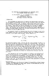
consumption <strong>of</strong> <strong>plastic</strong>s. Our previous study [l] demonstrated that, at 440 "C and 60<br />
min reaction time, liquid-phase cracking using tetralin and n-decane solvents increased<br />
oil yields from polystyrene (PS) but decreased oil yields from high-density polyethylene<br />
(HDPE), when compared to the crackings in solvent-free environment. Significant oil<br />
yield synergism was further observed for the cracking <strong>of</strong> PS and HDPE mixtures when<br />
sufficient hydrogen stabilization from the solvent was absent.<br />
Our research continued to study the type <strong>of</strong> catalyst that may be applied to the<br />
liquid-phase cracking <strong>of</strong> <strong>plastic</strong>s. This communication reports the effects <strong>of</strong> an FeZOdS<br />
catalyst, which is known for hydrogenolysis activities, on the liquid-phase cracking <strong>of</strong> PS<br />
and HDPE and their 50/50 mixtures.<br />
EXPERIMENTAL<br />
Figure 1 illustrates the experimental scheme <strong>of</strong> the liquid-phase cracking using a<br />
batch-mode 300-mL autoclave reactor. The <strong>plastic</strong>s used were commercial-grade<br />
pellets <strong>of</strong> PS and HDPE. Reagent-grade tetralin, n-decane (n-C10) and decalin (cis-<br />
and trans- mixture) were used as the solvent for liquid-phase cracking without further<br />
purification. For catalytic runs, powders <strong>of</strong> 3 wt% iron(ll1) oxide and 2.4 wi% sulfur, both<br />
based on the total weight <strong>of</strong> feed <strong>plastic</strong>s, were added.<br />
A total weight <strong>of</strong> 80 g <strong>of</strong> feed reactants including the <strong>plastic</strong>s and the liquid solvent,<br />
if used, was charged for each autoclave reaction experiment. The concentration <strong>of</strong> the<br />
<strong>plastic</strong>s in each experiment with solvent feed was generally 25 wi% except for the cases<br />
investigating the effect <strong>of</strong> decalin dilution on PS and HDPE crackings. Experiments<br />
were also performed under solvent-free environment for comparison purposes. For<br />
mixtures <strong>of</strong> PS and HDPE, the ratio <strong>of</strong> PS to HDPE was 111 on a w/w basis. After being<br />
charged with feed reactants, the reactor was purged and then filled with nitrogen gas for<br />
non-catalytic runs, or with hydrogen gas for catalytic runs. The initial pressure was 4.0<br />
MPa (570 psig) at ambient temperatures. The reaction was conducted at 440 "C for 60<br />
min with constant stirring at 1000 rpm.<br />
The volume <strong>of</strong> produced gases was measured using a wet gas meter and the<br />
composition analyzed using a GC equipped with a TCD. The yield and the average<br />
molecular weight <strong>of</strong> gaseous products were determined based on the gas volume<br />
measured and the gas composition analyzed. The product liquid slurry was distilled<br />
under a vacuum pressure as low as 1 torr at 330 "C. The recovered liquid distillate was<br />
further analyzed using another GC equipped with a 50-m long glass capillary column<br />
(Hewlett Packard Ultra-1) and an FID. The oven temperature <strong>of</strong> the GC unit was<br />
controlled starting from 60 "C at a 3.0 Wmin rate to 300 "C, at which it was kept<br />
isothermally for a period <strong>of</strong> 30 min. A GC-MS was used to assist the identification <strong>of</strong> the<br />
components <strong>of</strong> interest.<br />
The total conversion was determined according to the following equation:<br />
total conversion, wt% = oo% - wt. <strong>of</strong> vacuum residue - wt. <strong>of</strong> catalyst as FeS<br />
net wt.<strong>of</strong> feed<strong>plastic</strong>s<br />
The oil yield was calculated by subtracting gas yield from the total conversion. For<br />
catalytic runs, the catalyst was assumed to have transformed to FeS after the reactions.<br />
The hydrogen consumption was calculated by determining the loss <strong>of</strong> hydrogen in the<br />
charged hydrogen gas less the amount consumed for the formation <strong>of</strong> hydrogen sulfide.<br />
972
I<br />
\<br />
M3ULTS AND DISSCUSSION<br />
Crackina <strong>of</strong> ps<br />
AS illustrated in Table 1, the total conversion at 440 "C <strong>of</strong> the non-catalytic thermal<br />
runs Was found to follow the order that tetralin > decalin > n-decane > SOlVent-free. The<br />
hydrogen donation capabilities <strong>of</strong> decalin and n-decane are essentially negligible, as<br />
compared to that <strong>of</strong> tetralin. Figure 2 shows the effect <strong>of</strong> decalin dilution, in terms <strong>of</strong> PS<br />
feed concentration, on the conversion and product selectivity. At a high temperature <strong>of</strong><br />
440 "c, secondary reactions quickly transform styrene, which is considered the primary<br />
product <strong>of</strong> PS cracking [2, 31, to products such as ethylbenzene, toluene, and cumene.<br />
With the increased interactions among reactive species, condensation reactions could<br />
prevail during the PS cracking. For the solvent-free case, the interactions among<br />
product species were the most intensive and the conversion could not be improved in<br />
the absence <strong>of</strong> sufficient hydrogenation. Results from GC-MS analysis <strong>of</strong> the oil<br />
fractions show that components such as terphenyls, quatterphenyls, and polyphenyls <strong>of</strong><br />
higher order might have formed in the heavy fractions.<br />
At 440 "C, tetralin not only buffered but also quickly stabilized reactive species by<br />
hydrogenation. For the case <strong>of</strong> catalytic cracking using Fe20JS catalyst and decalin<br />
solvent, the total conversion increased to completion with a low gas yield <strong>of</strong> 0.6 wt%.<br />
The high conversions obtained for the cracking in tetralin and catalytic hydrogenation<br />
environments suggest that hydrogen stabilization could promote PS conversion to<br />
produce light oil.<br />
The gas yields from PS cracking were generally low except when using n-decane<br />
as the solvent. Substantial amounts <strong>of</strong> Cl-C4 n-alkanes were produced in gaseous<br />
products when n-decane was used as the solvent at 440 "C. This suggests that n-<br />
decane could be susceptible to decomposition during PS cracking.<br />
Crackinq <strong>of</strong> HDPE<br />
Typical product yields <strong>of</strong> HDPE cracking in the different reaction environments are<br />
presented in Table 2. At 440 "C, HDPE cracking shows the trend opposite to PS<br />
cracking by giving decreased total conversions in the presence <strong>of</strong> the solvents. This is<br />
mainly due to the different cracking mechanisms <strong>of</strong> HDPE and PS. At 440 "C. HDPE<br />
decomposition slowly produces a series <strong>of</strong> successive n-alkanes and a-alkenes. For<br />
the solvent-free environment, intensive interactions led to a moderately high conversion<br />
<strong>of</strong> 55.6 wt%. However, for the cracking in tetralin solvent environment, the total<br />
conversion was sharply reduced to a negligible level. At 440 "C, tetralin appeared to<br />
stabilize decomposition radical fragments at quite fast rates, slowing down the<br />
production <strong>of</strong> distillate oil from HDPE. The use <strong>of</strong> n-decane and decalin non-donor<br />
solvents under nitrogen atmosphere also significantly suppressed HDPE decomposition<br />
by dispersing the interactions among reactive species. The order <strong>of</strong> average molecular<br />
weight (MW) <strong>of</strong> gaseous products follows the same trend for the cracking in both PS<br />
and HDPE under the non-catalytic environments, showing that n-decane > solvent-free<br />
> decalin > tetralin. It is evident that tetralin effectively reduced the chances <strong>of</strong> further<br />
interactions. When n-decane was used as the solvent for HDPE cracking, small<br />
amounts <strong>of</strong> n-alkanes and a-alkenes with the carbon chain lengths less than 7 were<br />
produced, suggesting that n-decane could also be susceptible to decomposition during<br />
the HDPE cracking.<br />
The cracking <strong>of</strong> HDPE using Fe2OdS catalyst under hydrogen atmosphere in<br />
decalin solvent gave a total conversion substantially higher than that <strong>of</strong> the<br />
corresponding non-catalytic run. This indicates that the catalyst may have a cracking<br />
activity to increase the rate <strong>of</strong> HDPE decomposition to produce distillate oil in heavy<br />
fraction. The hydrogen consumption was low, and the catalyst showed quite different<br />
behaviors from tetralin in that the catalyst was able to hydrogenate a-olefins and<br />
showed cracking activity with HDPE. Only small concentrations <strong>of</strong> a-olefins and<br />
branched alkanes were found in the oil fraction obtained from the catalytic run.<br />
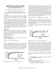
The effect <strong>of</strong> decalin dilution on product selectivity <strong>of</strong> HDPE cracking is illustrated in<br />
Figure 3. As the HDPE feed concentration increased, both the oil and gas yields also<br />
increased. However, a decrease in total conversion did not occur for high HDPE feed<br />
loadings. Although black soot-like material was observed on the reactor wall and<br />
around stirrer shaft surfaces, occurrence <strong>of</strong> condensation reactions in HDPE cracking at<br />
440 "C appeared not as severe as in PS cracking. Unlike PS, HDPE does not readily<br />
convert to its monomer precursor. When a normal alkane molecule is decomposed, it<br />
973
probably first converts to a pair <strong>of</strong> n-alkane and a-alkene, which may or may not have<br />
the same chain lengths. Figure 3 indicates that, as the conversion becomes greater,<br />
the selectivity increases for lighter n-alkanes whereas it remains relatively constant or<br />
slightly decreases for lighter a-alkenes under the non-catalytic environment. The<br />
carbon distribution pattern further indicates that HDPE cracking may start with random<br />
cleavage on the carbon-carbon main chains and then followed by p-scission to the free<br />
radical positions, producing n-alkanes and a-alkenes <strong>of</strong> various chain lengths.<br />
Crackina <strong>of</strong> PS and PE Mixtures<br />
Table 3 presents the results Of non-catalytic and catalytic liquefaction runs for 50/50<br />
PS and PE mixtures at 440 "c for 60 min. For the non-catalytic thermal runs, strong<br />
interactions among the cracking products from PS and HDPE mixtures result in oil yield<br />
synergism 111. The results further show that the combination <strong>of</strong> Fez03 and sulfur<br />
provides an effective way for hydrogenation, simply by judging from the hydrogen<br />
consumed from the gas phase. The order <strong>of</strong> hydrogen consumption based on the<br />
charged HP agrees well with the hydrogen need during the <strong>plastic</strong>s cracking. The<br />
solvent-free run required the most hydrogen because <strong>of</strong> its high concentration (Le., 100<br />
wt%) <strong>of</strong> the mixed <strong>plastic</strong>s, when compared with other runs that used 25 wt% loading<br />
with a solvent medium. The catalytic run using tetralin as the solvent consumed the<br />
least amount <strong>of</strong> hydrogen from the gas phase, due to the affluent hydrogen supply from<br />
the 5olvent. For those runs using decalin and n-decane as the solvent media, their<br />
hydrogen consumption requirements were intermediate.<br />
In Table 3 except the case using n-decane solvent, the total conversions and C5-<br />
C9 n-alkanes yields decreased by the application <strong>of</strong> Fe20dS catalyst. This is attributed<br />
to the effective catalytic hydrogenation that is able to stabilize reactive species and<br />
suppress the oil yield synergism. The catalyst clearly exhibited its activities increasing<br />
the selectivity for light aromatic components produced from the PS cracking, stabilizing<br />
the reactive species, and suppressing HDPE from induced cracking.<br />
When n-decane was used as the solvent, the production <strong>of</strong> C5-C9 n-alkanes was<br />
exceedingly high from both the non-catalytic and catalytic runs, when compared to other<br />
reaction environments. The total conversion <strong>of</strong> the catalytic run was not decreased but<br />
slightly increased. This may be explained as a combined result <strong>of</strong> induced and<br />
accelerated cracking <strong>of</strong> HDPE by PS decomposition products, n-decane cracking, and<br />
the cracking and hydrogenation activities <strong>of</strong> the catalyst.<br />
PS decomposes to styrene at a temperature as low as 400 "C. As indicated in<br />
Table 1, the cracking <strong>of</strong> PS could significantly induce the cracking <strong>of</strong> n-decane below a<br />
temperature at which the hydrogenation could take place to stabilize reactive species.<br />
Other solvents such as tetralin and decalin are more stable than n-decane and were not<br />
susceptible to PS-induced cracking into reactive species. Moreover, it is also noted that<br />
the slow cracking <strong>of</strong> HDPE at 440 'C might also slightly induce the cracking <strong>of</strong> n-<br />
decane, or vice versa. under the non-catalytic condition. Under the combined effect, the<br />
decomposition <strong>of</strong> HDPE could be induced and accelerated by the presence <strong>of</strong> reactive<br />
species from both n-decane and PS cracking, giving the high yields <strong>of</strong> C5-C9 n-alkanes<br />
and n-alkylbenzenes with C6-C9 side chains.<br />
When using the Fe20dS catalyst, although slightly more cracking could occur for<br />
HDPE to produce oils in heavy fraction, there also exists a hydrogen stabilization effect<br />
from the gas phase counteracting the induced cracking <strong>of</strong> HDPE. This leads to an<br />
overall result <strong>of</strong> slightly increases in total conversion and oil yield. The GC<br />
chromatogram indicates that less concentrations <strong>of</strong> a-olefins and branched alkanes<br />
were contained in the oil produced from the catalytic runs. Interaction products such as<br />
n-alkylbenzenes with C6-CS side chains were also present in the oil fractions but<br />
generally in smaller yields.<br />
PS cracking at 440 "C could proceed much faster than the effective hydrogenation.<br />
For the major products from PS, ethylbenzene selectivity was sharply increased and<br />
became the most dominant component probably due to direct hydrogenation to the<br />
styrene during both liquid- and gas-phase hydrogenations. The trend for other<br />
components also follows in similar fashions for their variations, namely, the selectivity<br />
for cumene increased while for toluene decreased.<br />
The rate <strong>of</strong> HDPE cracking may be slowed down to an extent depending on the<br />
reaction environment either by using tetralin solvent or Fe20dS catalyst in hydrogen<br />
atmosphere. Tetralin was able to stabilize decomposition free radicals but was not as<br />
974
I<br />
I<br />
i<br />
effective as the catalyst in the hydrogenation <strong>of</strong> unsaturated bonds. There would need<br />
significantly additional hydrogen supply if HDPE could have been cracked effectively.<br />
The existence <strong>of</strong> oil yield synergism produces more varieties <strong>of</strong> components by<br />
increased interactions. The catalytic cracking <strong>of</strong> PS and HDPE mixtures in n-decane<br />
solvent showed a high conversion with a low gas yield.<br />
CONCLUSIONS<br />
Fe203/s catalyst showed a hydrogenation activity for the cracking <strong>of</strong> PS in a non-<br />
hydrogen donor solvent at 440 "C to yield a total conversion <strong>of</strong> 100 wt%. It<br />
demonstrated an effective way <strong>of</strong> converting PS using liquid-phase cracking and a<br />
hydrogenation catalyst. The catalyst slightly increased the conversion <strong>of</strong> HDPE under a<br />
similar condition by exhibiting cracking and hydrogenation activities. When used in the<br />
cracking <strong>of</strong> PS and HDPE mixtures, the catalyst decreased total conversions by<br />
suppressing interactions among reactive products under solvent-free, tetralin, and<br />
decalin environments. When n-decane was used as the solvent for the cracking <strong>of</strong> PS<br />
and HDPE mixtures, the catalyst was able to maintain effective decomposition <strong>of</strong> PS<br />
and HDPE, and give a decreased gas yield in hydrogen atmosphere.<br />
ACKNOWLEDGEMENTS<br />
This work was performed under STA Research Fellowship arranged by the <strong>National</strong><br />
Science Foundation, USA, and the Science and Technology Agency, Japan. The<br />
author J.-P. Anthony Wann likes to express his sincere thanks to Pr<strong>of</strong>essors David M.<br />
Bodily and Larry L. Anderson, <strong>of</strong> University <strong>of</strong> Utah, and Dady E. Dadyburjor, <strong>of</strong> West<br />
Virginia University, for their supports <strong>of</strong> this research.<br />
REFERENCES<br />
1. Wann, J.-P. A., Kamo, Y., Yarnaguchi, H., and Sato, Y., "Reaction Behaviors <strong>of</strong><br />
Mixed Plastics in Liquid-Phase Cracking," ACS Preprint, Div. Fuel Chern., 41 (4),<br />
1161-1 164, (1996).<br />
2. Stevens M. P., Polvmer Chemistrv: An Introduction, Addition-Wesley Publishing,<br />
Reading, Massachusetts, 1975, p. 206.<br />
3. Lin, R and White, R. L., "Catalytic Cracking <strong>of</strong> Polystyrene," ACS Preprint, Div. Fuel<br />
Chem., 41(4), 1165-1169, (1996).<br />
3<br />
975
PS. HDPE Fe203/ S tetralin, n-C10, decalin<br />
T=440"C, t=60min<br />
P = 4.0 MPa N2 or Hz (cold), 1000 rpm<br />
Slurry Product Gaseous Product<br />
+ GC Analysis<br />
T=330 "C, PP 1 torr<br />
Gas Volume Measurement<br />
Vacuum Residue<br />
Distillate<br />
GC, GCMS Analyses<br />
Figure 1. Schematic Illustration <strong>of</strong> Plastics Liquefaction Experiment<br />
$100.<br />
'5 OF--- \----..<br />
a- 80<br />
-<br />
Oil Yield ----<br />
0 20 40 60 80 100<br />
PS Concentration in Feed, wt%<br />
Figure 2. Effect <strong>of</strong> Decalin Solvent Dilution on PS Cracking at 440 "C and<br />
60 min (Legend: 0 ethylbenzene 0 cumene V toluene A propylbenzene<br />
benzene V styrene 0 oil)<br />
L<br />
S; 0.5 1<br />
.- c<br />
.-<br />
> 0.4<br />
c<br />
$ 0.3<br />
5 0.2<br />
0.1<br />
0.0<br />
0<br />
\<br />
PE Feed Conc.. X Conversion. rvrX<br />
.O 25 20.7<br />
0 50 25.4<br />
a 0 75 35.5<br />
A A 100 55.6<br />
5 10 15 20 25 30<br />
Carbon Number<br />
Figure 3. Effect <strong>of</strong> Decalin Dilution on PE Cracking at 440 "C and 60 min<br />
976<br />
f<br />
I
I<br />
1.<br />
!<br />
I<br />
7<br />
Table 1. Product Yields <strong>of</strong> PS Cracking in Different Reaction Environments at 440 "C<br />
Reaction Environment Non-Catalytic, NP<br />
Solvent-Free Tetralin Decalin n-Decane<br />
Total Conversion, wt% 73.2 96.5 91.8 89.0<br />
Oil Yield, wt%<br />
benzene, wt%<br />
toluene, vd%<br />
ethylbenzene, wt%<br />
styrene, wi%<br />
curnene, wt%<br />
propylbenzene, wt%<br />
72.9<br />
0.9<br />
21.6<br />
27.4<br />
0.0<br />
6.6<br />
1.3<br />
95.8<br />
0.2<br />
40.8<br />
27.7<br />
0.5<br />
5.5<br />
1.5<br />
90.8<br />
0.4<br />
33.8<br />
21.2<br />
0.4<br />
4.1<br />
1.4<br />
83.8<br />
0.7<br />
33.3<br />
13.4<br />
0.5<br />
3.7<br />
1.6<br />
Gas Yield, wt%<br />
Gas MW (average)<br />
Hydrogen Consumption'<br />
Wt% <strong>of</strong> <strong>plastic</strong>s<br />
Wt% <strong>of</strong> HP charged<br />
0.3<br />
18.1<br />
0.7<br />
5.6<br />
1 .o<br />
10.2<br />
5.1<br />
30.2<br />
Reaction Environment<br />
Total Conversion,wt%<br />
Oil, wt%<br />
C5C9 n-alkanes<br />
n-alkylbenzenes with<br />
C6C9 side chains<br />
Toluene, wt%<br />
Ethylbenzene,wt%<br />
Cumene, wt%<br />
Gas, wt%<br />
Gas MW (average)<br />
H2 Consumption*<br />
~ wt% <strong>of</strong> <strong>plastic</strong>s<br />
wt% <strong>of</strong> HP charged<br />
Solvent-Free Tetralin Decalin<br />
Thermal Catalylic Thermal Catalytic Thermal Catalyii<br />
81.5 . 70.2 55.6 51.6 78.4 66.6<br />
80.3 69.1 55.1 51.2 76.8 65.9<br />
5.9 1.4 0.4 0.2 2.1 1.0<br />
1.1 0.2 0.3 0.2 1.1 1.0<br />
19.9 14.2 19.4 5.7 19.1 13.2<br />
16.4 21.6 12.7 29.4 8.1 21.5<br />
3.3 4.8 2.7 5.2 1.1 4.2<br />
1.2 1.1 0.5 0.4 1.6 0.7<br />
23.2 36.0 4.4 41.7 15.9 33.7<br />
Catalytic, H2<br />
Decalin<br />
100.0<br />
99.4<br />
0.7<br />
24.4<br />
41.4<br />
0.8<br />
18.4<br />
Table 2. Product Yields <strong>of</strong> HDPE Cracking in Different Reaction Environments at 440 "C<br />
Reaction Environment<br />
Total Conversion, wt%<br />
Oil Yield, wt%<br />
C5C9 n-alkanes, wt%<br />
Gas Yield, wt%<br />
Gas MW (average)<br />
HI Consumption'<br />
wt% <strong>of</strong> <strong>plastic</strong>s<br />
wt% <strong>of</strong> HP charged<br />
Non-Catalytic, N2 Catalytic, HP<br />
1.7 0.6 2.2 0.7<br />
27.5 5.5 22.6 31.3 45.1<br />
I 0.1<br />
Table 3. Results <strong>of</strong> Non-Catalytic Thermal and Catalytic Liquefaction Runs for 50/50 PS<br />
and PE Mixtures at 440 "C for 60 min<br />
0.6 0.4 0.7<br />
50.S 9.1 17.0<br />
977<br />
n-Decane<br />
Thermal Catalytic<br />
76.0 79.4<br />
72.7 77.2<br />
17.6 17.8<br />
3.9 1.0<br />
20.4 12.5<br />
5.1 23.3<br />
0.8 2.0<br />
3.2 2.1<br />
28.1 33.0<br />
0.9<br />
20.9
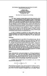
Effect <strong>of</strong> Solid Acid Catalysts on Waste Plastic Liquefaction<br />
J. Rockwell, N. Shah and G.P. Huffman<br />
CFFLS, 533 S. Limestone St.<br />
University <strong>of</strong> Kentucky<br />
Lexington, KY 40506<br />
Keywords: <strong>plastic</strong>, solid acid catalyst, liquefaction.<br />
Introduction<br />
The use <strong>of</strong> solid acid catalysts for liquefaction <strong>of</strong> <strong>plastic</strong> and coprocessing <strong>of</strong> coal with <strong>plastic</strong><br />
has proven effective. (I-') However, very good results have been obtained under thermal<br />
liquefaction conditions and there is some question as to whether the use <strong>of</strong> a catalyst is justified.<br />
In the current study, seven different catalysts were tested with two <strong>waste</strong> <strong>plastic</strong>s: a relatively<br />
clean <strong>waste</strong> <strong>plastic</strong> provided by the American Plastics Council and a somewhat dirtier <strong>plastic</strong><br />
provided by the Duales System Deustchland (DSD). Liquefaction experiments were carried out<br />
at 435 and 445 "C on the APC <strong>plastic</strong> and at 445 "C on the DSD <strong>plastic</strong>.<br />
The results at 435 "C show significant differences in the total conversions and oil yields.<br />
However, at 445 "C, the liquefaction yields with different catalysts showed relatively small<br />
differences. For the APC <strong>plastic</strong>, simulated distillation measurements on the oil fraction<br />
obtained at 445 "C did show significant differences. The oils from most <strong>of</strong> the catalytic runs<br />
exhibited higher fractions <strong>of</strong> gasoline (BP - 200°C) and kerosene (200 - 275 "C) and lower<br />
fractions <strong>of</strong> heavy oils 275 - 550 "C). The HZSM-5 zeolite catalyst was found to be the most<br />
effective. The catalysts were less effective for the DSD <strong>plastic</strong>, possibly because <strong>of</strong> poisoning.<br />
Exoerimental Procedure<br />
All liquefaction experiments were performed using 50 ml tubing bomb microreactors. The<br />
feedstocks were a commingled <strong>waste</strong> <strong>plastic</strong> obtained from the APC and a post consumer <strong>waste</strong><br />
<strong>plastic</strong> provided by the DSD. The APC <strong>plastic</strong> has been used in a number <strong>of</strong> previous<br />
experiments. (2.'' It is a relatively clean <strong>waste</strong> <strong>plastic</strong> that has been subjected to a wet washing<br />
process to remove labels and inerts. The DSD sample is the same <strong>plastic</strong> feedstock used in the<br />
German feedstock <strong>recycling</strong> industry. As discussed elsewhere, (9) this material is subjected to<br />
sorting, automated cleaning by magnetic, eddy current, air and screen separation techniques,<br />
shredding, and agglomeration. The proximate and ultimate analyses <strong>of</strong> these materials are given<br />
in Table I.<br />
Table 1. Proximate and ultimate analyses <strong>of</strong> the APC and DSD <strong>waste</strong> <strong>plastic</strong>s (wt. YO).<br />
Approximately I O g <strong>of</strong> feedstock was weighed and placed in a tubing bomb. Catalyst was added<br />
at a 1 wt. % concentration (0.lg). The bomb was then purged with H2 gas and charged to a final<br />
cold pressure <strong>of</strong> 200 psig. The apparatus was immersed into a fluidized sand bath at the desired<br />
temperature and agitated at 400 rpm. All <strong>of</strong> the data reported here were obtained from<br />
experiments run at 435 "C for 30 minutes or 445 "C for 60 minutes. After liquefaction, the<br />
sandbath is lowered and the tubing bomb is air-cooled to room temperature. The gas is collected<br />
in a 40 ml gas bomb and weighed. The remaining sample is analyzed by conventional solvent<br />
extraction methods. The total liquid conversion is the THF extractable material, while the oil<br />
yield is defined as the pentane soluble liquid. Asphaltenes + preashpaltenes (A + PA) are<br />
defined as the product that is soluble in THF but not in pentane.<br />
For each reaction condition, two samples were run. A sample <strong>of</strong> the liquid product was taken<br />
directly from the second tubing bomb and subjected to simulated distillation (SIMDIS) analysis<br />
using a Perkin-Elmer gas chromatograph with the following operating parameters: column -<br />
Petrocol B, 20' X 1/8" packed column; temperature - -10 to 360 "C with IO "C/min ramp;<br />
978
L<br />
I<br />
i<br />
,<br />
detector- FID at 380°C; flow rate - 35 m hin He. SIMDIS s<strong>of</strong>tware provided by Perkin-Elmer<br />
was used to analyze the data. The results are reported as boiling point (BP) ranges as follows:<br />
gasoline - IBP-200 "C; kerosene - 200-275 "C; and heavy oil - 275-550 "C.<br />
Seven different catalysts were used in the liquefaction experiments. These included a<br />
commercial HZSM-5 zeolite, (lo) a ZrO2/WO3 catalyst, ('I) and a number <strong>of</strong> catalysts synthesized<br />
in our laboratories. The latter included femhydrite treated with citric acid (FHYDKA), (I2' a<br />
femhydrite containing with 5 % Mo (FHYD/Mo), (I3) a SiOz-AI203 binary oxide, (" and two<br />
Ti02-Si02 binary oxides with different atomic ratios ([Ti]/[Ti+Si]) = 0.85 and 0.85(+)) prepared<br />
using the method <strong>of</strong> Doolin et al. (I4)<br />
Liauefaction Results<br />
The liquefaction results are shown in Figures 1-3 for the APC <strong>plastic</strong>s. At 435 "C, the HZSM-5<br />
catalyst gives the best oil yield and total liquid yield. However, it is not much more effective<br />
than the other catalysts tested. Furthermore, the yield results obtained with no catalyst (thermal)<br />
are as good as or better than those obtained with all <strong>of</strong> the catalysts tested except HZSM-5. At<br />
445 "C, there is little or no difference in the yields obtained from the thermal run and the various<br />
catalytic runs. The simulated distillation results, however, show that the catalysts do have an<br />
effect on the quality <strong>of</strong> the oil product. It is seen that the thermal run gives a gasoline fraction <strong>of</strong><br />
about 27%, while the HZSD-5 oil product exhibited a gasoline fraction <strong>of</strong> 42%. The other<br />
catalysts gave intermediate gasoline fractions, ranging from 28% for the SiOz-AI203 to 38% for<br />
the Ti02-Si02 ([Ti]/[Ti+Si]=0.95).<br />
Some results for the DSD <strong>waste</strong> <strong>plastic</strong> are shown in Figures 4 and 5. At 445 "C, it is again seen<br />
that the addition <strong>of</strong> a catalyst has very little effect. A high oil yield is obtained thermally, and no<br />
significant change occurs as a result <strong>of</strong> adding 1 wt. % <strong>of</strong> any <strong>of</strong> the catalysts. Additionally, the<br />
preliminary SIMDIST results on these samples indicate that the catalysts also have very little<br />
effect on oil quality. The experiments on the DSD <strong>plastic</strong>s will be completed with all catalysts at<br />
both temperatures. Chemical analyses on the oil products will be performed to determine the<br />
effect <strong>of</strong> the catalysts on heteroatom content, particularly CI.<br />
Conclusions<br />
The current results indicatc that, at high liquefaction temperatures (445 "C), low concentrations<br />
(-1 wt. %) <strong>of</strong> solid acid catalysts have relatively small effects on either the yield or the quality <strong>of</strong><br />
products derived from liquefaction <strong>of</strong> <strong>waste</strong> <strong>plastic</strong>. Although further testing is needed, this<br />
suggests that thermal hydroprocessing <strong>of</strong> <strong>waste</strong> <strong>plastic</strong>s at 440-450 "C is adequate to produce a<br />
good oil product. This would decrease the operating costs <strong>of</strong> any commercial developments <strong>of</strong><br />
this technology. ('I<br />
Acknowledgement: The authors would like to acknowledge the US. Department <strong>of</strong> Energy for<br />
supporting this research under DOE contract No. DE-FC22-93-PC93053 as part <strong>of</strong> the research<br />
program <strong>of</strong> the Consortium for Fossil Fuel Liquefaction Science.<br />
References:<br />
1. M.M. Taghiei, Z. Feng, F.E. Huggins, and G.P. Huffman, 1994, Energy & Fuels, 1228-1232.<br />
2. Z. Feng, J. Zhao, J. Rockwell, D. Bailey and G.P. Huffman, 1996, Fuel Proc. Tech., 49,17-<br />
30.<br />
3. W.B. Ding, W. Tuntawiroon, J. Liang, L.L. Anderson, 1996, FuelProc. Tech., 49,49-63.<br />
4. M. Luo and C.W. Curtis, 1996a, Fuel Proc. Tech., 49,91-117.<br />
5. W. Zmierczak, Xin Xiao, Joseph Shabtai, 1996, Fuel Proc. Tech., 49,31-48.<br />
6. J. Shabtai, X. Xiao, and W. Zmierczak, 1997, Energy &Fuels, 11, 76-87.<br />
7. X. Xiao, W. Zmierczak and J. Shabtai, 1995, Amer. Chem. Soc., Div. Fuel Chem. Preprints,<br />
40(1), 4-8.<br />
8. .K.R. Venkatesh, J. Hu, W. Wang, G.D. Holder, J.W. Tiemey and I. Wender, 1996, Energy &<br />
Fuels, 10, 1163-1170.<br />
9. G.P. Huffman, "Feasibility Study for a Demonstration Plant for the Liquefaction and<br />
Coprocessing <strong>of</strong> Waste Polymers and Coal," paper in this volume and DOE report (in<br />
preparation).<br />
10. HZSM-5 provided by Dr. Fred Tungate, United Catalysts Corporation.<br />
11, zroz/wo3 prepared by Dr. Francis Acholla, Rohm & Haas Corporation.<br />
12.1. Zhao, Z. Feng, F.E. Huggins and G.P. Huffman, 1994, Energy & Fuels, 8, 11 52-3.<br />
13. J. Zbao, Z. Feng, F.E. Huggins and G.P. Huffman, 1994, Energy & Fuels, 8, J. Zhao, Z.<br />
Feng, F.E. Huggins and G.P. Huffman, 1994, Energy & Fuels, 8,38-43.<br />
14. P.K. Doolin et al., 1994, Catalysis Letters, 38,457.<br />
979
70<br />
60<br />
50<br />
40<br />
30<br />
20<br />
10<br />
0<br />
Figure 1. Llquelacliin yields a1 435 C, 2W pslg n2 (cold). 60 minutes.<br />
Figure 2. Liquefaction yields at 445 C, 200 psig HZ(coId), 60 minutes.<br />
Figure 3. Comparison Ot simdi51 resuits lor themi and catalytic runs.<br />
0 Garaiins<br />
0 Kam-<br />
iSi TiSi(85+) IYDlCA FHKVMo MZNV03 liSi(85) HZSM-5<br />
980<br />
mi
.<br />
J<br />
60<br />
50<br />
40<br />
30<br />
20<br />
10<br />
0<br />
Figure 4. Liquefaction yields for DSD <strong>plastic</strong> at 445 C.<br />
Figure 5. Simdist results for oil from DSD <strong>plastic</strong><br />
Gasoline<br />
6l Kerosene<br />
Thermal HZSM-5 Zr02iW03<br />
981<br />
W A+PA<br />
0 Oil
EFFECTS OF CATALYST ACIDITY AND SlRUClUFE ON POLYMFB<br />
CRACKING MECHANISMS<br />
Rong Lin, Darrel L. Negelein, and Robert L. White<br />
Department <strong>of</strong> Chemistry and Biochemistry<br />
University <strong>of</strong> Oklahoma, Norman, OK 73019<br />
Keywords: catalytic cracking, polymer cracking, polymer <strong>recycling</strong><br />
INTRODUCIlON<br />
Communities in the United States need alternatives to municipal solid <strong>waste</strong><br />
landfilling. Of the solid <strong>waste</strong> components currently placed into landfills, <strong>plastic</strong>s are<br />
particularly undesirable because <strong>of</strong> their limited biodegradability. A variety <strong>of</strong> <strong>plastic</strong> <strong>waste</strong><br />
<strong>recycling</strong> methods have been established and new <strong>recycling</strong> approaches are being developed<br />
to avoid placing polymers into landfills. One approach to <strong>waste</strong> <strong>plastic</strong> <strong>recycling</strong>, known<br />
as tertiary <strong>recycling</strong>, consists <strong>of</strong> converting <strong>plastic</strong>s into useful <strong>chemical</strong>s. The development<br />
<strong>of</strong> efficient processes for <strong>waste</strong> <strong>plastic</strong> tertiary <strong>recycling</strong> will require detailed fundamental<br />
data on the direct catalytic cracking <strong>of</strong> polymers without complications due to reactions <strong>of</strong><br />
primary cracking products with polymer residue. Secondary reactions can be minimized<br />
by maintaining high catalyst to polymer ratios and providing efficient and rapid removal<br />
<strong>of</strong> volatile products. This york was carried out to investigate the potential use <strong>of</strong> catalytic<br />
cracking to convert <strong>plastic</strong>s <strong>waste</strong>s into mixtures <strong>of</strong> useful <strong>chemical</strong>s. The effects <strong>of</strong> silica-<br />
alumina, HZSM-5 zeolite and sulfated zirconia catalysts on the thermal degradations <strong>of</strong><br />
poly(ethylene), poly(propy1ene) and poly(styrene) are described.<br />
EXPERIMENTAL<br />
Samples examined in this study were: poly(ethy1ene) (PE) (MW=80,300),<br />
poly(propy1ene) (PP) (MW= 250,000), poly(styrene) (PSI (MW=SSO,OOO), and these<br />
polymers coated on silica-alumina, HZSM-5, and sulfated zirconia cracking catalysts (10-<br />
20% (wt/wt)). All polymer samples were purchased from Aldrich Chemical Company<br />
(Milwaukee, WI). The silica-alumina catalyst was provided by Condea Chemie GmbH<br />
(Hambug, Germany) and contained 11.8% by weight alumina and had a surface area <strong>of</strong><br />
282 m2/g. The HZSM-5 zeolite was obtained from Mobil Oil (Paulsboro, NJ) and was<br />
characterized by a 1.5% alumina content and a 355 m2/g surface area. The sulfated<br />
zirconia catalyst was synthesized by following procedures described previously'']. The<br />
sulfated zirconia catalyst had a surface area <strong>of</strong> 157 m2/g and contained 9% by weight<br />
sulfate. Polymer/catalyst samples were prepared by dissolving polymers in proper solvents,<br />
adding catalyst, and then rotoevaporating the mixture to remove solvents. The resulting<br />
PE and PP coated catalyst samples were dried at 120oC, and the PS coated catalyst samples<br />
were dried at 90 C for several hours.<br />
The apparatus used for pyrolysis-GC/MS, TG-MS andTG-GC/MS measurements have<br />
been described previo~sly~~*~~. Pyrolysis separations were achieved by using a HP 5890<br />
capillary GC with a DB-5 column (0.25 pm film thickness). The gas chromatograph oven<br />
temperature program consisted <strong>of</strong> a 2 min isothermal period at -50°C followed by a<br />
S0C/min ramp to 40°C followed by a 100C/min ramp to 28OoC, and then isothermal at<br />
28OoC for 5 minutes for PE and PP samples. For PS samples, the GC oven temperature<br />
programs consisted <strong>of</strong> a 2 minute isothermal period at -50°C followed by a 1OoC/min<br />
ramp to 28OoC, and then another isothermal period at 280DC for 5 minutes. For TG-MS<br />
studies, samples were heated from 50°C to 6OODC at nominal heating rates <strong>of</strong> 1, 10, 25,<br />
and SOWmin, with a He purge gas flow rare <strong>of</strong> 50 mL/min. For TG-GC/MS studies, a<br />
Vako Instruments, tnc. (Houston, TX) eight port heated sample injector was employed to<br />
divert small volumes (ca. 100 1L) <strong>of</strong> TG effluent into a 30 m DB-5 capillary column (0.25<br />
km film thickness). TG-GC/MS signal averaged mass spectra were acquired at rates<br />
ranfig from one to two per second, depending on the mass range that was scanned. A<br />
5 Wmin He camer gas flow rate through the TG-GC/MS chromatographic column was<br />
employed for all separations. TG-GC/MS column effluent was split prior to entering the<br />
mass spectrometer to maintain an ion source pressure <strong>of</strong> 5 x 10.~ torr.<br />
982
RESULTS AND DISCUSSION<br />
Figure 1 shows pyrolysis GC/MS results for neat PE and PE/catalyst samples<br />
obtained at 500 oc and demonstrates the dramatic effects <strong>of</strong> catalysts on PE thermal<br />
All four chromatograms shown in Figure 1 were obtained by using the<br />
Same separation conditions and they are plotted on the same time scale. The bottom<br />
chromatogram represents the volatile products from pyrolysis <strong>of</strong> neat PE at 500°C and<br />
contains numerous high molecular weight species. However, in the presence <strong>of</strong> cracking<br />
catalysts, more than 85% <strong>of</strong> volatile products were hydrocarbons in the C, to C,, range.<br />
Therefore, the effect <strong>of</strong> the catalyst was to restrict the molecular weight range <strong>of</strong> volatile<br />
products, leading to the formation <strong>of</strong> low molecular weight species. With increasing<br />
catalyst acidity, more saturated hydrocarbons were produced relative to unsaturated<br />
hydrocarbons. Large amounts <strong>of</strong> aromatics were detected for the sample containing HZSM-<br />
5 zeolite. The most abundant volatile products generated by PE cracking were isoalkenes,<br />
which differs from previous reports that isoalkanes were the primary products. However,<br />
the mechanisms proposed for isoalkane formation require protonation <strong>of</strong> initially formed<br />
alkenes followed by hydride abstraction from the polymer residue. The rapid removal <strong>of</strong><br />
volatile products during cracking minimized secondary reactions and therefore was an<br />
effective means to study the effects <strong>of</strong> catalysts on the initial polymer cracking reactions.<br />
TG-MS results indicated that poly(ethy1ene) cracking on all three catalysts occurred in<br />
three steps. Saturated and unsaturated hydrocarbons evolved in the first two steps and<br />
aromatics evolved in the third step.<br />
Pyrolysis GC/MS results for neat PP and PP/catalyst samples obtained at 500 OC are<br />
shown in Figure 2. The presence <strong>of</strong> catalysts led to the preferred formation <strong>of</strong> low<br />
molecular weight species. Volatile product distributions depended on the choice <strong>of</strong><br />
catalyst[". It was found that the most abundant neat PP thermal degradation volatile<br />
products were C, to C,, olefin homologues separated by three carbon atom intervals. The<br />
most abundant saturated volatile products were C, alkanes. Catalytic cracking <strong>of</strong> PP/SA<br />
samples produced a significantly different volatile product distribution than neat PP thermal<br />
degradation. The most abundant volatile products were C, C, and C, alkenes. The amount<br />
<strong>of</strong> char remaining on catalyst surfaces was found to be approximately 1% <strong>of</strong> the initial<br />
polymer mass. In the presence <strong>of</strong> Zr02/S0, catalyst, the most abundant volatile products<br />
were saturated hydrocarbons. All <strong>of</strong> the volatile products detected were C,, or smaller.<br />
However, an increase in unsaturated volatile product yields was found at higher<br />
temperature. The significant difference between PP/Si-Al and PP/ZrO,/SO, cracking<br />
products indicates that catalyst acidity plays a vital role in determining volatile product<br />
slates. Sulfated zirconia, a very strong acid catalyst, si1 Mcantly lowered the temperature<br />
at which catalytic cracking occurred and facilitated hydride abstractions, resulting in large<br />
yields <strong>of</strong> saturated hydrocarbons and the formation <strong>of</strong> large amounts <strong>of</strong> residue (ca. 15%).<br />
Like the PP/Si-AI sample, the PP/HZSM-5 sample yielded primarily unsaturated volatile<br />
products. The organic residue left on catalysts was estimated to be approximately 1%. In<br />
contrast to the PP/Si-Al and PP/Zr02/S0, samples, HZSM-5 channels restricted reaction<br />
volume, which resulted in relatively large yields <strong>of</strong> alkyl aromatics.<br />
Catalytic cracking mechanisms <strong>of</strong> PS also differ considerably from the thermal<br />
degradation mechanisms[61. Pyrolysis GC/MS results (Figure 3) indicate that styrene was<br />
the most abundant volatile product resulting from neat PS thermal degradation. The<br />
relative yield <strong>of</strong> styrene was 68% when PS was pyrolyzed at 400 "C. However, benzene<br />
was the most abundant product when PS was catalytically cracked. The relative yield <strong>of</strong><br />
benzene was found to be as high as 60% for the PS/HZSM-5 sample and over 30% for<br />
samples containing Si-Al and sulfated zirconia catalysts. Very little styrene was detected<br />
for all three PS/catalyst samples. TG-GC/MS results for the PS/Zr02/S0, sample are<br />
shown in Figure 4. The broken line in this figure denotes the TG weight loss curve for the<br />
sample. Polymer decomposition occurred primarily between 150 and 350 oC. The second<br />
weight loss step results from the decomposition <strong>of</strong> the catalyst. The solid line in Figure 4<br />
denotes the TG-GC/MS total ion current, which is plotted as a function <strong>of</strong> the TG<br />
temperature at which GC injections were made. This plot contains 31 separate<br />
chromatograms obtained during one TG weight loss analysis. It can be seen that at low<br />
temperature there is only one peak, corresponding to benzene. With the increasing <strong>of</strong><br />
temperature, more peaks appear in chromatograms, indicating the formation <strong>of</strong> more<br />
cracking products. Peaks at high temperature (i.e > 400 "C) correspond to the formation<br />
<strong>of</strong> SO, and suggest that the sulfated zirconia catalyst decomposed. Figure 5 shows a TG-<br />
GC/MS chromatogram obtained from TG effluent that was injected when the TG sample<br />
983
temperature was 240 oC. More than 25 peaks were detected in this chromatogram. The<br />
broken line in Figure 5 denotes the GC oven temperature ramp employed for separations,<br />
It was found that benzene was by far the most abundant volatile product and was<br />
produced at temperatures well below those at which the other volatile products were<br />
detected. All <strong>of</strong> the PS/catalyst samples produced alkyl benzenes and indanes, but styrene<br />
and indenes were only detected for samples containing HZSM-5 zeolite.<br />
TG analyses were carried out to investigate the effects <strong>of</strong> catalysts on volatilization<br />
activation energies. TG weight loss data obtained by using different heating rates (1, 10,<br />
25 and 50 OC/min) were used to calculate volatilization activation energies by using the<br />
method described by Friedman[”. Volatilization activation energies calculated from TG<br />
weight loss information are given in Table 1. The highest volatilization activation energies<br />
were obtained for the neat polymer samples. All three catalysts lowered the activation<br />
energy for PE thermal degradation significantly. The order <strong>of</strong> catalyst activities was found<br />
to be in the order <strong>of</strong> increasing catalyst acidity: ZrOJSO, > HZSM-5 > Si-AI.<br />
CONCLUSIONS<br />
The effects <strong>of</strong> different catalysts on catalytic cracking product distributions derived<br />
from polymer/catalyst samples were studied. It was found that volatile product<br />
distributions were affected by the choice <strong>of</strong> catalyst as well as the cracking conditions. In<br />
general, catalysts caused volatile hydrocarbon products to be smaller than neat polymer<br />
thermal decomposition products. Overall volatilization activation energies for PE, PP, and<br />
PS thermal decompositions were considerably reduced by the presence <strong>of</strong> cracking catalysts<br />
and the magnitude <strong>of</strong> the reduction depended directly on the catalyst acidity. A lowering<br />
<strong>of</strong> the overall volatilization activation energies by cracking catalysts is desired for polymer<br />
<strong>recycling</strong> applications because it greatly reduces the cracking temperature required to<br />
decompose <strong>plastic</strong> <strong>waste</strong>s, which, reduces operational costs <strong>of</strong> the process.<br />
ACKNOWLEDGEMENT<br />
Financial support for this work from the <strong>National</strong> Science Foundation (CTS-<br />
9509240) is gratefully acknowledged.<br />
REFERENCES<br />
1. A. Jatia, C. Chang, J.D. MacLeod, T. Okubo, M.E. Davis, Cam. Leu., 5, 21(1994).<br />
2. R.L. White, J. Anal. Appl. Pyr., 18, 269(1991).<br />
3. E.C. Sikabwe, D.L. Negelein, R. Lin, R.L. White, Anal. Chem., in press.<br />
4. R. Lin, R.L. White, J. Appl. PoZym. Sci., 58, 1151(1995).<br />
5. D.L. Negelein, R. Lin, R.L. White, J. Appl. PoZym. Sci., submitted<br />
6. R. Lin, R.L. White, J. Appl. Polym. Sci., 63, 1287(1997).<br />
7. H.L. Freidman, J. Polyrn. Sci., 6C, 183(1963).<br />
Table 1. Volatilization Activation Energies (kcal/mol)<br />
Catalyst<br />
Si-Al 3723 33fl 3921<br />
HZSM-5<br />
Zr02/S0,<br />
31 f 1 29 f 1 36 & 1<br />
28 f 2 27 f 1 29 2 2<br />
984
L HZSMJ<br />
c35<br />
A . Pure PE<br />
0 10 20 30 40 50 60 70 80<br />
Time (rnin)<br />
Figure 1 - 500 OC pyrolysis GUMS chromatograms for poly(ethy1ene) samples.<br />
il, .,, , , ll,. . , PPM 0 10 20 30 40 50 60 70 80<br />
Time (min)<br />
Figure 2 - 500 "C pyrolysis GUMS chromatograms for poly(propy1ene) samples.<br />
985
dimer trimer<br />
11 A. Neat PS<br />
I I<br />
0 10 20 30 40 50<br />
30000<br />
15000<br />
0<br />
100 200<br />
Time (min)<br />
Figure 3 - 400 "C pyrolysis GUMS chromatograms for poly(styrene) samples.<br />
75000<br />
- 100<br />
- 98<br />
60000<br />
45000<br />
-<br />
-96 e<br />
$<br />
-94<br />
.***..I, ,( ,<br />
***.*...*<br />
-11,<br />
*e...<br />
-3..<br />
***.......,<br />
1 1 1 1 l l I I I I I<br />
Sample Temperature ("C)<br />
s<br />
-92 *e M<br />
- 90 P<br />
- 88<br />
,' 86'<br />
Figure 4 - TG-GUMS weight loss curve (dotted line) and chromatograms (solid line) for<br />
the PSIZrO,ISO, sample.<br />
G<br />
30000<br />
- 200 ow<br />
24000<br />
18000<br />
-180 180 8<br />
1<br />
-160 160 5<br />
12000 -140 140<br />
a)<br />
a<br />
E<br />
b<br />
6000<br />
-120 120 0<br />
100 u<br />
0<br />
r3<br />
0.0 0.5 1.0 1.5 2.0 2.5 3.0 r3<br />
0.0 0.5 1.0 1.5 2.0 2.5 3.0<br />
Retention Time (min)<br />
Figure 5 - TG-GCIMS chromatogram measured at 240 OC.<br />
986
I<br />
I<br />
1<br />
I<br />
,<br />
Iotroduction<br />
CATALYTIC DEGRADATION OF MGH DENSITY POLYETHYLENE<br />
AND WASTE PLASTIC BELOW 200 "c<br />
G.S. Deng, W.H. McCleunen, H.L.C. Meuzelaar, Center for<br />
Micro Analysis and Reaction Chemistry, University <strong>of</strong> Utah, S.L.C, UT841 12<br />
High density polyethylene (HDPE) is the dominant component <strong>of</strong> several major <strong>waste</strong> <strong>plastic</strong><br />
streams. Furthermore, under thermally as well as catalytically controlled degradation conditions,<br />
HDPE is clearly an excellent potential source <strong>of</strong> hydrocarbon products. Unfortunately, HDPE is<br />
notoriously resistent agamst thermal degradatiou, requiring pyrolysis temperatures well above 400°C<br />
in order to exhibit sufficiently high degradatiou rates[ I]. These high temperatures lead to loss <strong>of</strong><br />
selectivity, increased secondary reactions, coke formation and reduced catalyst life. Although<br />
Waider et al. reported catalytic scission <strong>of</strong> polymetliyleuic bonds at temperatures as low as 160°C<br />
in short chain paraffinic compouuds such as hexadecane[Z], few authors have reported successful<br />
catalytic conversion <strong>of</strong> HDPE below 300 "C. The two main obstacles encountered appear to be the<br />
limited mobility <strong>of</strong> long cbain molecules even iu the molten stage and poor hydrogen (HJ diffusion,<br />
thus leading to transport-limited iuteractions between catalytic sites and potential bond scission sites.<br />
Also tbe 6equnit preseuce <strong>of</strong> orgauic and iuorgauic moieties other than HDPE.that negatively affect<br />
catalyst performance, e.g. though catalyst deactivation ("fouling") poses a formidable obstacle<br />
against successful catalytic convertions <strong>of</strong> <strong>waste</strong> <strong>plastic</strong>. Attempts to reduce transport limitations for<br />
loug chain HDPE molecules have included use <strong>of</strong>very high catalyst loadmgs[3], or improved mixing<br />
and blending tecKiques for catalyst and polymer e.g. by means <strong>of</strong> cryogenic milling[4] or through<br />
solvent blending[3].<br />
The present research was concerned with a systematic investigation <strong>of</strong> the catalytic degradation <strong>of</strong><br />
HDPE polymers at low temperature under H, pressure, using hely dispersed superacid catalysts,<br />
i.e. WZrOJSO,. A Cabu model 15 I high pressure thermogravimetiy (HPTG) system with specially<br />
constructed on-he gas cluomatography/mass spectrometry (GC/MS module) capable <strong>of</strong> recordiug<br />
temperature programed GC/MS pr<strong>of</strong>iles at 90 second iutervals provides detailed kinetic (rates,<br />
yields) and mechanistic (product identity) information fiom a siugle HPTG iun.<br />
Experimental<br />
Materials. Four ditfereut HDPE samples were studied: (1) a pure HDPE (den., 0.96g/cm3;<br />
average MW, 250,000; Tm, 135 "C) provided by HTI and originally manufactured by Solvay<br />
polymers; (2) a pure HDPE (den., 0.959 g/cm'; average MW, 125,000; Tm, 130°C) obtained 6om<br />
Aldrich Chemical Co.; (3) a HDPE-rich commingled <strong>waste</strong> <strong>plastic</strong> sample (primaiily HDPE with 5-<br />
10% polypropylene, 3-5% polystyrene aud I-2% iuorganic fillers plus orgauic coloriziug agents)<br />
provided by the American Plastics Council (APC) and included in the University <strong>of</strong> Utah Waste<br />
Materials Sample Bank; (4) a cleaned lnilk bottle without its cap aud label.<br />
Catalysts. The solid superacid catalysts ZrOJSO, and F't-stabilized ZrOJSO,( 0.5%Pt ), were<br />
prepared by Wender and Shabtai as described in previous papers[2,5]. The zeolite-based HZSM-5<br />
catalyst was supplied by Aldrich Chemical Co.<br />
Experimental Procedure. Experiments with high density polyethylene (HDPE) and HDPE-rich<br />
<strong>waste</strong> <strong>plastic</strong> iu the presence <strong>of</strong> various catalysts were performed in a high pressure TG/GC/MS<br />
system under different hydrogen pressures (or helium). Details <strong>of</strong> the high pressure TG/GC/MS<br />
system have been described previously[6]. Different temperature programs were employed to better<br />
distinguish the effect <strong>of</strong> different conditions on reaction kioetics.<br />
Dq- blending <strong>of</strong> catalyst and polymer was performed by hand miXing the powdered material inside<br />
a quartz TG crucible with a thin metal rod. To achieve better bleiidiug <strong>of</strong> catalyst and polymer,<br />
30 mg polymer samples were dissolved in IO ml <strong>of</strong> toluene at about 100 "C. After the addition <strong>of</strong><br />
catalyst, the mixture was shaken d e the solvent was removed and then dried for 3 hours at<br />
130°C. Sample quantities <strong>of</strong> 30-40 mg were used iu each TG/GC/MS experiment.<br />
Results and Discussion<br />
Catalyst loading and sohrent blending<br />
Figure la demonstrates that both a catalyst (here at 16% loading) and hydrogen atmosphere are<br />
987
needed to achieve sustaiued high degradation rates at 375 "C. However increased hydrogen pressure<br />
above 600 psig does not produce markedly higher rates at this temperature. Figure lb indicates that<br />
improved blending <strong>of</strong> polymer and catalyst using a solution sluny method H toluene cau be as<br />
effective as increasing catalyst loadings. Interestingly, the first weight loss appears to occur just<br />
above 200 "C. As shown in Figure IC, increasing the catalyst loading to 25% leads to complete<br />
decomposition <strong>of</strong> HDPE below 300 "C during the heat-up phase. Even a (much less reactive) <strong>waste</strong><br />
<strong>plastic</strong> sample shows more than 40% weight loss before reaching the isothermal heating stage at<br />
375 "C under these conditions. Therefore, it appears that physical (transport related) process are rate<br />
Limiting in the case <strong>of</strong>HDPE polymer. Ifso, higlier conversion rates aud lower reaction temperatures<br />
should be achievable by measures that increase catalyst loadings and facilitate contact between the<br />
catalyst surface and the polymer matrix.<br />
These observations encouraged us to go to much lower temperatures as well as higher catalyst<br />
loadings. Figure 2a sbows that very fast degradatiou rates can be aclueved at 200 "C and 600 psig<br />
H, wheu usiiig pure HDPE mid Pt stabkd ZrO,/SO, at 50 % loading whereas oidy miuimal weiglit<br />
loss is obseived wlieu using solveut blending <strong>of</strong> 50% no11 Pt stabilized ZrO,/SO, or 50% HZSM-5.<br />
Clearly, HZSM-5 induced rates are not euhauced by the same factor as the superacid catalyst rates.<br />
Apparently, the rate limiting step is not affected by just increasing the amount <strong>of</strong> catalyst surface<br />
available. Possibly other factors such as diffusion into the HZSM-5 zeolite cavity may be rate<br />
limiting here, as also evident in figure la. Reduction <strong>of</strong> the H2 pressure to 25 psig causes marked rate<br />
reduction. However, Mer increase <strong>of</strong> catalyst loading to 70% can largely eubance the reactiou rate<br />
and yield as shown in figure 2b.<br />
The reaction conditions illustrated in figure 2b are worth contemplating a little fiuther, as they<br />
suggest that HDPE in more or less pure form can nearly be degraded in a household style pressure<br />
cooker (200 "C and 25 psig), thus potentially reducing the high cost <strong>of</strong> bigb temperature, (high)<br />
pressure reaction vessels, and auxilaiy systems.<br />
Temperature<br />
Figure 3a and b illustrate the effect <strong>of</strong> temperature on the reaction rates <strong>of</strong> two different HDPE<br />
model compounds, obtained 60m HTI (MW: 250,000) and Aldrich (MW: 125,000) respectively.<br />
Note that the HDPE from HTI appears to be more reactive (iu spite <strong>of</strong> its higher MW) both with<br />
regard to maximum rate achieved as well as highest conversion yield. The cause <strong>of</strong> the nearly 10%<br />
residue in the Aldrich sample at 200 "C is tluknowu. Tlus is uot simply char formation, since all <strong>of</strong><br />
the residue is converted at 400 "C. Further studies are underway to explain this phenomeuou.<br />
Pressure <strong>of</strong> H2<br />
Figure 4 a,b,c illustrate the effect <strong>of</strong> changes in H, pressure on the two different pure HDPEs and<br />
on a HDPE-rich <strong>waste</strong> <strong>plastic</strong> sample. The HTI sample degraded faster and more completely at<br />
200 "C than the Aldrich sample. Furthennore, figure 4c illustrates that nearly 80% <strong>of</strong> the <strong>waste</strong><br />
polymer sample can be converted at 200 "C.<br />
Sorted <strong>waste</strong> <strong>plastic</strong><br />
The effects <strong>of</strong> contaminants, additives or residues on the conversion behavior <strong>of</strong> <strong>waste</strong> polymers<br />
are also well recognized. Avariety <strong>of</strong> organic(e.g. sulfur or nitrogen contaiuiug) and inorganic (e.g.<br />
heavy metal containiug) compounds are known to be capable <strong>of</strong> deactivating catalysts. Amoug the<br />
catalysts kuown to be effective in degradating polymethyleuic bonds, the superacids are known to<br />
behighly susceptible to activity loss through coke deposit formation. Figure 5 shows the bebaviour<br />
<strong>of</strong> a variety <strong>of</strong> <strong>waste</strong> <strong>plastic</strong> samples indicating wide differences iu the reactivity <strong>of</strong> the specific <strong>waste</strong><br />
<strong>plastic</strong> components which were hand-picked fiom the APC sample, e.g. clear (HDPE rich) materials,<br />
white (filled) cap compoiients and labels (or label like) material. hdividual component pr<strong>of</strong>iles and<br />
mixture pr<strong>of</strong>iles are shown iu figure 5. Note how the clean milk bottle sample degraded as fast as<br />
pure HDPE model compound. "Cap material" behaves much like a moderately char formiug<br />
polymer. Note that the initial 30% residue formed at 200 "C nearly completely degrades at approx.<br />
450 "C, thus reducing the Likelihood that a inorganic filler is responsible for the observed residue.<br />
Finally, the paperflabel Wte fraction (handpicked ) does not show any detectable weight loss below<br />
300 'C. The mixture samples <strong>of</strong> "paper" + "<strong>plastic</strong>" and "paper" + "cap" + "<strong>plastic</strong>" show marked<br />
residue formation. The fact that the measured conversion rates and yields fall well behind the<br />
predicted rates <strong>of</strong> summed weight loss curves <strong>of</strong> the components suggest the effects <strong>of</strong> catalytic<br />
deactivation.<br />
By examing the evolution pr<strong>of</strong>iles <strong>of</strong> volatile products by means <strong>of</strong> GC/MS, the distribution <strong>of</strong><br />
988<br />
P
I<br />
dierent types <strong>of</strong> product distributions as a function <strong>of</strong> reaction gas and catalysts can be measured.<br />
Figure 6 shows that effective catalysts increase the degree <strong>of</strong> saturation and markedly decrease the<br />
degree <strong>of</strong> aromaticity (nearly zero) in addition to increasing reaction rates and decreasing reaction<br />
temperature as shown in Figure 1. HZSM-5 also showed a tendency to promote the formation <strong>of</strong><br />
aromatic products (not shown here) as noted in previous expeihents[7]. In addition, the product<br />
distributions <strong>of</strong> thermal reaction in H2 or He are different, although their reaction rates are nearly the<br />
same as show in Figure la. Typical analytical results corresponding to cwe 3 in Figure 2a are<br />
demonstrated in Figure 7. The repetitive chromatogram for the whole run (Figure 7a) indicates that<br />
the catalytic decomposition <strong>of</strong> HDPE occurs in the about 1635 minutes run time (200 "C<br />
isothermal) Furthermore, by selecting a particular ion chromatogram, the evolution ratio <strong>of</strong> the<br />
correspondiug products duriug the reaction can be visualized. The expanded total ion chromatomam<br />
for one sampling iutelval (Figure 7b) shows the range <strong>of</strong> GC separated paratfin products which are<br />
d a r to the products for nou Pt promoted ZrOJSO, "[7]. The predomiuance <strong>of</strong> saturated aliphatic<br />
products is shown in the 15 to 37 minute average mass spectrum (7c).<br />
Conclusions<br />
Platinum stabilized ZrO,/SO, '- (WZrOJSO, ") is much more effective than non promoted<br />
ZrO,/SO, '- in maiiitaiiiiug liigli coiiversiou rates for HDPE polymers aiid HDPE-rich <strong>waste</strong> <strong>plastic</strong><br />
at 200°C. Also, it readily outperfomis HZSM-5. Eveii uuder low pressure (25 psig H2) couditioiis,<br />
Pt/ZrO,/SO, '. sliows high activity by ineaiis <strong>of</strong> liigli catalyst loaduig aiid solvent bleiidiug. 111<br />
addition, there are wide differences in the reactivity <strong>of</strong> the various <strong>waste</strong> <strong>plastic</strong> components over<br />
Pt/ZrO,/SO,z'. Furthermore, the on-line GCNS moiutorhg techuique <strong>of</strong>fers an effective tool in<br />
studying catalytic conversion processes.<br />
References<br />
(1) Siauw H. Ng, H. Seoud, M. Stanciulescu, Y. Sugioloto, Energy&Fuels, 1995, 9, 735-742.<br />
(2) M.Y. Wen, I. Wender and J.W. Tierney, Energy&Fuels,1990,4, 372-379.<br />
(3) RL. White and R. Lin, in Proceedings at Frontiers <strong>of</strong> Pyrolysis, Colorado, in press.<br />
(4) M. Seehra, E. Hopkins, V. Suresh Babu.M. Ibrahim, the 10' Annual Technical Meeting : The<br />
Cousortiuin for Fossil Fuel Liquefaction Science, August 6-9, 1996, PA, p. 36.<br />
(5) J. Shabtai, X. Xiao, W. Zinierczak, Eiiergy&Fuels,I997, I I(I), 76-87.<br />
(6) K. Liu, E, Jakab, W.H. McCleuiieti aiid H.L.C. Meuzelaar, Am. Cliem. SOC., Div. Fuel<br />
Chem., Prepr.,1993,38(3), 823-830.<br />
(7)K. Liu, H.L.C. Meuzelaar, Fuel Processing Technology, 1996,49, 1-15.<br />
Acknowledgements<br />
The authors are gratell to Dr L.L.Anderson for helpful advice, discussions as well as Drs Wender,<br />
Shabtai, aiid XinXiao for preparing the superacid catalysts. This work was supported by the U.S.<br />
Departmeut <strong>of</strong> Energy through the Coiisortiuni for Fossil Fuel Liquefaction Science (Grant No.<br />
UKRF-4-43576-90- IO).<br />
989
1W 500 Fig. 1 a) Effect <strong>of</strong> different reaction<br />
pressures (600,900, 1200 psig),<br />
E<br />
P E" s (loading 16%; Cat.A=Pt/ZrOz/SOs;<br />
3oo Cat.B=HZSM-5) on decomposition<br />
1 40 2w<br />
<strong>of</strong> HDPE (MW=250,000).<br />
b) Solvent blending (toluene) and<br />
I<br />
PtiZrOdS04 loading (1 :20 or 1 :5)<br />
1<br />
20<br />
1w<br />
at 600 psig Hz<br />
c) Pt/ZrOz/S04 loading 25% f<br />
0 30 at 600 psig Hz<br />
e4 4~ atmospheres Hz, He), and catalysts I<br />
1M<br />
20<br />
0<br />
Time (mi")<br />
Fig. 2 a) Effect <strong>of</strong> different catalysts at 50% loading at 600 psig H2.<br />
b) Effect <strong>of</strong> different catalyst loadings at 25 psig H2.<br />
990
Tms (min) Time (mln)<br />
Fig. 3 Effect <strong>of</strong> temperature on degradation <strong>of</strong> different HDPEs at 600 psig HZ<br />
with PtlZrOdS04 loading 50%<br />
a) HTI HDPE(MW=250,000), b) Aldrich HDPE(MW=125,000)<br />
Time (min)<br />
Time (min)<br />
Fig. 4 Effect pressure on decomposition<br />
<strong>of</strong> different HDPEs at 200 C<br />
(Pt/ZrOz/S04 loading 50%).<br />
a) HTI HDPE (MW=250,000)<br />
b) Aldrich HDPE (MW=125,000)<br />
c) Waste <strong>plastic</strong><br />
991
Fig. 5 TG pr<strong>of</strong>iles for decomposition<br />
<strong>of</strong> components <strong>of</strong> <strong>waste</strong> <strong>plastic</strong> at 0.00 0.04 0.08 0.12 0.16 C<br />
Aromaticity index *<br />
PUZrOdSO4 loading 50% (except 1)<br />
Fig. 6 Comparison <strong>of</strong> evolution<br />
product's saturation and aromaticity<br />
with different PtlZrOJSO. catalyst<br />
loadings and pressures<br />
(1 ) (mh77+rnh91 )l(mh43tm/z57)<br />
(2) (rnh43+m/z57)l(mh4~ +mh55)<br />
Fig. 7 GC/MS analysis corresponding to Curve 3<br />
in Fig. 2a.<br />
a) Total ion chromatogram.<br />
b) Total ion chromatogram for one sampling interval.<br />
c) Average mass spectrum from 15 to 37 minute from 7a.<br />
992<br />
,
\<br />
I<br />
AN INTEGRATED APPROACH TO THE RECOVERY OF FUELS<br />
AND CHEMICALS FROM MIXED WASTE CARPETS<br />
THROUGH THERMOCATALVIC PROCESSING<br />
Carolyn C. Elam, Robert J. Evans, and Stefan Czernik<br />
<strong>National</strong> Renewable Energy Laboratory<br />
1617 Cole Boulevard, Golden, Colorado 80401<br />
Keywords: Waste Carpet Recycling, Plastic Recycling, Pyrolysis<br />
INTRODUCTION<br />
The recovery <strong>of</strong> value from the growing volume <strong>of</strong> mixed polymers in post-consumer<br />
<strong>waste</strong> presents technical and economic challenges when compared to the typical<br />
methods <strong>of</strong> disposal by landfilling and mass burning, which have raised some<br />
environmental concerns, Included with typical polymer <strong>waste</strong>, which currently ends up<br />
in landfills, is nearly 3 billion pounds <strong>of</strong> carpet per year. The high value <strong>of</strong> the nylon-6,<br />
nylon-6/6, and polyester face fiber material is an incentive for their recovery. However,<br />
the nature <strong>of</strong> the carpet construction (face fiber woven into a mixed polymer and<br />
inorganic backing material) makes typical <strong>recycling</strong> methods, such as regrind and<br />
remelt, impractical and uneconomical. Integrated, thermocatalytic processing, starting<br />
with selective catalytic pyrolysis to recover the high value monomers and followed by<br />
gasification <strong>of</strong> the residual material to generate process energy, is an approach which<br />
has shown great promise for recovering the maximum value from this current <strong>waste</strong><br />
stream.<br />
Selective pyrolysis is a catalytic. thermal technique which optimize the differences in<br />
pyrolysis reaction rates. The pre-sorting requirements for feedstock preparation and the<br />
isolation and purification <strong>of</strong> pyrolysis products are minimized by controlling reaction<br />
conditions so that target products can be collected directly in high yields from the <strong>waste</strong><br />
stream.’ Figure 1 shows the approach used in this work, which has three major<br />
components: (1) identifying target <strong>waste</strong> streams, (2) developing techniques for the<br />
control <strong>of</strong> conversion processes, and (3) targeting the recovery <strong>of</strong> high-value <strong>chemical</strong>s,<br />
which are recovered in economically attractive yields. Technoeconomic assessments<br />
are used throughout the development process to characterize potential <strong>waste</strong> streams,<br />
identify areas in which improvements can be made, evaluate the overall economic<br />
attractiveness <strong>of</strong> the technology, and compare the technology to competing<br />
technologies.<br />
Target <strong>waste</strong>s include both high-value and high-volume systems. Examples <strong>of</strong> high-<br />
value <strong>waste</strong>s include the recovery <strong>of</strong> caprolactam from nylon-6 and bisphenol-A from<br />
polycarbonate, both <strong>of</strong> which currently sell for greater that $0.70 per pound. High-<br />
volume <strong>waste</strong>s include mixed bottles and residential <strong>waste</strong>. The high-volume <strong>waste</strong>s<br />
are <strong>of</strong> great importance, but the economics are not favorable due to the low value,<br />
generally less than $0.15 per pound, <strong>of</strong> the monomers and <strong>chemical</strong>s which can be<br />
recovered.<br />
In the initial stages <strong>of</strong> the work, numerous small scale screening experiments are<br />
necessary to identify the appropriate catalyst(s) and conditions to optimize the<br />
separation and recovery for each <strong>of</strong> the <strong>waste</strong> streams. Milligram scale experiments<br />
can be studied using pyrolysis molecular beam mass spectrometer (MBMS). The<br />
effective quenching <strong>of</strong> species in their sampled state through free-jet expansion makes<br />
MBMS a valuable tool for identifying pyrolysis product^.^^^ Figure 2 shows a schematic<br />
<strong>of</strong> the MBMS used for these experiments. Milligram samples <strong>of</strong> the <strong>plastic</strong>s are<br />
thoroughly mixed with catalyst in a small metal boat. The boat is subsequently inserted<br />
into a furnace where hot helium gas is used to sweep the pyrolysis vapors through the<br />
reactor. A portion <strong>of</strong> the vapors are expanded across the stage one orifice on the apex<br />
<strong>of</strong> a cone. The orifice is the entrance to a low-pressure chamber and the pressure<br />
difference is sufficient for free-jet expansion. which preserves both light and heavy<br />
compounds produced upon pyrolysis. A second expansion collimates a molecular<br />
beam, which is introduced into the ion source <strong>of</strong> the mass spectrometer.<br />
Unlike other pyrolysis-mass spectrometric techniques, large samples can be employed<br />
in MBMS studies. The product evolution curves for four <strong>of</strong> the major <strong>packaging</strong> <strong>plastic</strong>s<br />
are shown in Figure 3. The mixture <strong>of</strong> pure <strong>plastic</strong>s was pyrolyzed by heating at a rate<br />
993
<strong>of</strong> 40Wmin in flowing helium. The rates <strong>of</strong> product evolution are shown by the key ion<br />
current curves that represent major products from each polymer. The times <strong>of</strong><br />
maximum product evolution for each polymer are different. This suggests that by use<br />
<strong>of</strong> a controlled heating rate, resolution <strong>of</strong> the individual polymer pyrolysis products may<br />
be possible, even for a complex, mixed, <strong>plastic</strong> <strong>waste</strong> stream. The PET-derived<br />
terephthalic acid (TPA) curve shows two maxima: the first at -350°C and the second<br />
at -450°C. The first maximum is the result <strong>of</strong> acid-catalyzed product formation. This<br />
demonstrates how a catalyst can be used to selectively influence the rate <strong>of</strong> product<br />
formation and allow the separation <strong>of</strong> product formation from other components <strong>of</strong> a<br />
mixture.<br />
Once the range <strong>of</strong> conditions has been sufficiently narrowed, bench-scale experiments<br />
can be performed using a stirred-batch or two inch fluidized bed reactor to enable<br />
product collection and analysis via conventional analytical techniques. A two inch glass<br />
fluidized bed reactor with a heated vacuum shroud enables obseivation <strong>of</strong> the melting<br />
characteristics <strong>of</strong> the material as it moves through the fluidizing medium, quickly<br />
identifying and heat or mass transfer limitations. After the conditions have been<br />
optimized in the two inch reactor, the process is transferred to a continuously fed,<br />
engineering scale, four inch fluidized bed reactor. This reactor allows for careful<br />
monitoring <strong>of</strong> temperature and pressure drops. Bed withdrawal enables the reactor to<br />
be run in a continuous mode. Validation <strong>of</strong> the process at this level enables the scale-<br />
up to a process development unit (25 kg/hour).<br />
TECHNOLOGY STATUS<br />
The selective pyrolysis technique has been demonstrated on recovering caprolactam,<br />
the monomer <strong>of</strong> nylon-6, from nylon-6 face fiber carpet, which currently accounts for<br />
around 30% <strong>of</strong> the carpet produced in the United States. A catalyst system allows<br />
caprolactam to be recovered at a lower temperature, leaving the polypropylene backing<br />
material and the styrene butadiene latex unreacted. Figure 4 shows a ramp and hold<br />
experiment, monitored by the MBMS, where nylon-6 and polypropylene are mixed in a<br />
steel boat with the catalyst. While the temperature is held around 400°C. Caprolactam<br />
from the depolymerization <strong>of</strong> nylon-6 is cleanly recovered. Subsequent heating <strong>of</strong> the<br />
sample pyrolyzes the polypropylene and demonstrates that all <strong>of</strong> the nylon-6 was<br />
depolymerized at the lower temperature. Additional catalyst screening identified a<br />
catalyst system which improved the depolymerization further, allowing the reaction<br />
temperature to be lowered while maintaining a rapid, clean separation <strong>of</strong> the<br />
components.<br />
Continuous tests were performed in a four inch fluidized bed reactor, using shredded<br />
whole carpet, and resulted in reproducible caprolactam yields <strong>of</strong> 85%. Economic<br />
analyses performed independently by industry representatives have shown that high<br />
purity caprolactam can be recovered from <strong>waste</strong> nylon-6 carpet for around $0.50 per<br />
pound for a plant which produces 100 million pounds <strong>of</strong> caprolactam per year. This<br />
estimate encompasses the complete process from collection to product purification and<br />
assumes that the polypropylene and styrene butadiene used in the carpet backing will<br />
be burned for process heat. The major contributor to the production cost is the price for<br />
collection and sorting which accounts for around half <strong>of</strong> the production cost (-$0.25 per<br />
pound <strong>of</strong> caprolactam produced).<br />
Other applications <strong>of</strong> the selective pyrolysis technology which have been or are being<br />
studied include: recovering dimethyl terephthalate (DMT) from PET containing <strong>waste</strong><br />
streams, such as polyester carpets, mixed bottles and polyester/cotton fabric blends;<br />
bisphenol-A from polycarbonate containing <strong>waste</strong>s, principally electronics; diisocyanates<br />
Or diamines from polyurethanes, both methylene and toluene based, from both<br />
automotive and appliance applications; phenol, cresol, and xylenol from phenolic resins;<br />
and styrene from polystyrene containing residential <strong>waste</strong>. The PET application is the<br />
furthest advanced (after the nylon-6 application). Two inch fluidized reactor results have<br />
shown that DMT is recovered from pure PET and mixed PET and polypropylene in<br />
yields <strong>of</strong> greater that 85% when methanol is used as a coreactant in conjunction with<br />
the catalytic selective pyrolysis. DMT can also be recovered from <strong>waste</strong> polyester fabric<br />
at comparable yields.<br />
994<br />
I
\<br />
I<br />
\<br />
FUTURE WORK<br />
Current efforts have turned to addressing the problem <strong>of</strong> the other face fiber materials,<br />
nYlon-6/6 and PET. The ultimate goal will be to eliminate the need to sort the carpet by<br />
face fiber material. It is envisioned that by combining selective pyrolysis with novel<br />
Purification and separation techniques, all carpets can be pyrolyzed simultaneously<br />
while maintaining the ability to separate and recover the valuable. The remaining<br />
material, both the backing material and the polyethylene and polypropylene face fiber<br />
carpet, will be combusted to fuel the process. An alternative to simply burning the low<br />
value material for process energy is to gasify it to produce a clean synthesis gas. This<br />
synthesis gas can be used as a feedstock for the production <strong>of</strong> a wide range <strong>of</strong><br />
<strong>chemical</strong>s.<br />
Successful demonstration <strong>of</strong> the selective pyrolysis approach to handling mixed carpets<br />
Will be expanded to a complete "Flexible Chemical Processing" technique, wherein any<br />
type <strong>of</strong> <strong>plastic</strong> <strong>waste</strong> will be handled at a single processing plant. Minimal on-sight<br />
sorting will be used to group high-value <strong>waste</strong>s which can undergo selective pyrolysis<br />
to recover the monomers or other high-value <strong>chemical</strong>s. The remaining <strong>waste</strong> can be<br />
gasified to recover synthesis gas. A portion <strong>of</strong> the synthesis gas will be used to supply<br />
energy for the plant, while the remaining will be converted to <strong>chemical</strong>s, such as<br />
methanol, further lessening the demand for petroleum feedstocks. It is estimated that<br />
approximately 10 billion pounds <strong>of</strong> textile, automotive, and home furnishings <strong>waste</strong> is<br />
available for collection per year. Currently, there are at least 25 major cities in the<br />
United States which could support a 200 million pound per year processing plant,<br />
resulting not only in an economic way to significantly reduced <strong>waste</strong>, but also in an<br />
energy savings <strong>of</strong> approximately 7 trillion Btu per year per plant.<br />
CONCLUSIONS<br />
Selective pyrolysis is a diverse technology which has shown promise for being able to<br />
recover high-value products from complex mixed <strong>plastic</strong> <strong>waste</strong> streams. The ability to<br />
recover caprolactam from <strong>waste</strong> nylon-6 carpet has been demonstrated to be both<br />
feasible and economical at the engineering scale. This technology combined with novel<br />
purification technology has the potential to significantly reduce the nearly 3 billion<br />
pounds <strong>of</strong> annual carpet <strong>waste</strong>. More importantly, high-value products like caprolactam,<br />
which sells for around $0.70 per pounds, are obtained and can be purified to the same<br />
grade as virgin material, lessening the demand for petroleum feedstock. Further<br />
expansion <strong>of</strong> this technology will yield the ability to handle even larger <strong>plastic</strong> <strong>waste</strong><br />
streams including other textiles, home furnishings, automotive dismantling residue, and<br />
residential <strong>waste</strong>s.<br />
REFERENCES<br />
1. Evans, R.J.; Tatsumoto. K.; Czernik, S.; and Chum, H.L., "Innovative Pyrolytic<br />
Approaches to the Recycling <strong>of</strong> Plastics to Monomers", Proceedings <strong>of</strong> the<br />
RecyclingPlas VI1 Conference: Plastics Recycling as a Business Opportunity,<br />
175 (1992).<br />
2.<br />
3.<br />
Atomic and Molecular Beams, Vol. 1. G. Scoles, ed., Oxford University Press,<br />
New York. 14-53 (1988).<br />
Evans, R.J. and Milne, T.A., Enerav & Fuels, 1(2), 123 (1987); 1(4), 31 1 (1987).<br />
995
Target Wastes Conversion Processes Target Products<br />
Waste Nylon Carpet<br />
(N6 + PP)<br />
Polyurethane<br />
(MDITTDI + POIYOIS)<br />
Engineerlng Blends<br />
Autoshredder Residue<br />
(PU/PVC/PP)<br />
Waste Bottles I I (PETIPWPVCIPP) ’ I<br />
Resldentlal I I (PS/PE/PVC) I<br />
Catalysis<br />
Information Resource for<br />
1 processes<br />
1 for<br />
I Valuable isolated<br />
Monomers<br />
(N6 caprolactam)<br />
Chemical Derlvatlves<br />
(Pu dlanlline)<br />
Secondary Products<br />
(liquid fuels)<br />
(enemy)<br />
Figure 1. Overview <strong>of</strong> the NREL approach to the <strong>chemical</strong> <strong>recycling</strong> <strong>of</strong> mixed <strong>plastic</strong>s.<br />
Three stage free-jet Triple quadrupole<br />
mass analyzer<br />
1” Diffusion T ~ &<br />
Molecular pump molecular<br />
~ Argon Turbo<br />
molecular<br />
drag pump<br />
pump gas pump<br />
0 +<br />
Figure 2. Schematic <strong>of</strong> Molecular Beam Mass Spectrometric (MBMS) sampling system.<br />
225 2M 275 300 325 350 375 400 425 450 475 5W 52<br />
Temperature, C<br />
-PVC-HCI -PE-hydrocarbons -PS-styrene - PET-TPA and esters<br />
Figure 3. Relative rates <strong>of</strong> pyrolysis for the four components <strong>of</strong> a mixture are shown in the<br />
time-resolved pr<strong>of</strong>ile plots <strong>of</strong> key ion for each polymer: PET - mlz 166, terephthalic acid;<br />
polystyrene (PS) - m/z 104, styrene; polyethylene (PE) - m/z 69, C,H,’, a typical fragment<br />
ion <strong>of</strong> alkenes; and polyvinylchloride (PVC) - m/z 36, HCI.<br />
996
\<br />
1<br />
Intensity, Arbitrary Units Temperaturi<br />
MR113<br />
............<br />
0 2 4<br />
1<br />
...............<br />
6 8 10<br />
Time, min<br />
Figure 4. The application <strong>of</strong> catalytic techniques allows the separation <strong>of</strong> nylon-6 derived<br />
caprolactam from polypropylene derived hydrocarbons.<br />
997<br />
500<br />
400<br />
300<br />
200<br />
100<br />
0
DISTRLBUTION KINETICS OF<br />
DEGRADING POLYMER MIXTURES<br />
Ciridhar Madras and Ben L McCoy<br />
Department <strong>of</strong> Chemical Engineering and Materials Science<br />
University <strong>of</strong> California, Davis, CA 95616<br />
email: bjmccoy@ucdavis.edu<br />
ABSTRACT<br />
Disposal <strong>of</strong> <strong>plastic</strong> <strong>waste</strong> is a worldwide problem that has prompted investigation <strong>of</strong><br />
<strong>plastic</strong>s <strong>recycling</strong>, including thermolysis methods. Most basic research on degradation, however,<br />
is for single polymers. Waste streams usually contain mixtures <strong>of</strong> polymers and it may be costly<br />
to separate them prior to degradation. Degradation rates depend on the mixture type, and adding<br />
another polymer can increase, decrease, or leave unchanged the degradation rate <strong>of</strong> the first<br />
polymer. Determining the decomposition mechanisms for polymer mixtures is <strong>of</strong> great interest<br />
for polymer <strong>recycling</strong>. In this study, we present techniqucs to determine the degradation kinetics<br />
<strong>of</strong> solubilized binary polymer mixtures by examining the time evolution <strong>of</strong> molecular-weight<br />
distributions (MWDs). Because the reaction mechanism for polymer degradation involves<br />
radicals, we have developed an approach fiat accounts for the elementary reactions <strong>of</strong> initiation,<br />
termination, hydrogen abstraction. and chain scission. We determined the concentration effect <strong>of</strong><br />
poly(a-methyl styrene) (PAMS) on the random-chain degradation <strong>of</strong> polystyrene dissolved in<br />
mineral oil at 275 OC in a batch reactor by evaluating the time evolution <strong>of</strong> the MWDs.<br />
Molecular-weight moments yielded expressions for the number- and weight-average MW and<br />
degradation rate coefficients. The experimental data indicated that the interaction <strong>of</strong> mixed<br />
radicals with polymer by hydrogen abstraction caused the random-chain scission degradation<br />
rate <strong>of</strong> polystyrene to decrease with increasing PAMS concentration.<br />
INTRODUCTION<br />
The rate <strong>of</strong> polymer degradation can be modified by the addition <strong>of</strong> conventional freeradical<br />
initiators, oxidizers or hydrogen donors but it might be easier to alter the degradation rate<br />
by blending two polymers (Gardner et al., 1993). Degradation studies by pyrolysis <strong>of</strong> polymer<br />
mixtures have reported varied results. For example, some reports indicated a significant<br />
interaction between polystyrene and polyethylene (Koo and Kim, 1993; Koo et al., 1991;<br />
McCaffrey et al., 1996). while others observed no interaction between these polymers (Roy et<br />
al., 1978; Wu et al., 1993). The pyrolytic polystyrene degradation rate was significantly<br />
enhanced in the presence <strong>of</strong> p~ ](methyl acrylate) and poly(huty1 acrylate) at 430 "C (Gardner et<br />
al., 1993). Richards and Salter (1964). on the other hand, observed that the rate <strong>of</strong> polystyrene<br />
degradation decreased with increasing molecular weight (MW) <strong>of</strong> added PAMS. These reports<br />
suggest the need for an analysis <strong>of</strong> the underlying reaction mechanisms.<br />
Degradation <strong>of</strong> polymers in solution has been proposed to ameliorate problems<br />
encountered in commercial applications (Sato et al., 1990). The degradation <strong>of</strong> polystyrene<br />
(Murakata et al., 1993; Madras et al., 1996~). poly(styrene-allyl alcohol) (Wang et al., 1995).<br />
poly(methy1 methacrylate) (Madras et al., 19963). PAMS (Madras et al., 1996b) in solution have<br />
been investigated. No studies on the degradation <strong>of</strong> polymer mixtures in solution, however, have<br />
been reported.<br />
EXPERIMENTS<br />
The HPLC (Hewlett-Packard 1050) system consists <strong>of</strong> a 100 pL sample loop, a gradient<br />
pump, and an on-line variable wavelcngth ultraviolet (UV) detector. Three PLgel columns<br />
(Polymer Lab Inc.) (300 mm x 7.5 mm) packed with cross-linked poly(styrene-divinyl benzene)<br />
with pore sizes <strong>of</strong> 100, 500, and 10,000 A are used in series. Tetrahydr<strong>of</strong>uran (HPLC grade,<br />
Fisher Chemicals) was pumped at a constant flow rate <strong>of</strong> 1.00 mL/min. Narrow MW<br />
polystyrene standards <strong>of</strong> MW 162 to 0.93 million (Polymer Lab and Aldrich Chemicals) were<br />
used to obtain the calibration curve <strong>of</strong> retention time versus MW. which was stable during the<br />
period <strong>of</strong> the experiments. The calibration curve, modeled as a second-order polynomial,<br />
indicates a higher accuracy in the measurement <strong>of</strong> lower MW polymers.<br />
The thermal decomposition <strong>of</strong> polystyrene in mineral oil was conducted in a 100 mL<br />
flask equipped with a reflux condenser to ensure the condensation and retention <strong>of</strong> volatiles. To<br />
observe a significant effect <strong>of</strong> PAMS on the conversion, polystyrene <strong>of</strong> high MW was chosen.<br />
60 mL <strong>of</strong> mineral oil (Fisher Chemicals) was heated to 275 OC. and various amounts (0 - 0.60 g)<br />
<strong>of</strong> monodisperse PAMS (MW = 11.000, Scientific Polymer Products), and 0.12 g <strong>of</strong><br />
monodisperse polystyrene (MW = 330,000, Aldrich Chemicals) were added. The temperature <strong>of</strong><br />
the solution was measured with a Type K thermocouple (Fisher Chemicals) and controlled<br />
within f 1 OC by a Omega CN-2042 temperature controller. Samples <strong>of</strong> 1.0 mL were taken at<br />
15 minute intervals and dissolved in 1.0 mL <strong>of</strong> tetrahydr<strong>of</strong>uran (HPLC grade, Fisher<br />
Chemicals). The chromatograph obtained by injecting 100 pL <strong>of</strong> this solution into the HPLC-<br />
GF'C system was converted to MWD. The peaks <strong>of</strong> the reacted polystyrene, PAMS, and the<br />
oligomers were distinct, so that moments could be calculated by numerical integration. Because<br />
the solvent mineral oil is UV invisible, its MWD was determined with a refractive index (RI)<br />
998
\<br />
I<br />
detector. No change in the MWD <strong>of</strong> mineral oil was observed when the oil was heated for 3<br />
hours at 275 O c without polystyrene.<br />
THEORETICAL MODEL<br />
According to the Rice-Herzfeld mechanism, polymers can transform without change in<br />
MW by hydrogen abstraction. Their radicals can also undergo chain scission to form lower MW<br />
products, or undergo addition reactions yielding higher MW products. Chain scission can occur<br />
either at the chain end yielding a specific product, or at a random position along the chain<br />
yielding a range <strong>of</strong> lower MW products.<br />
In the present treatment, two common assumptions simplify the governing equations.<br />
The long-chain approximation (LCA) (Nigam et al., 1994; Gavalas, 1966) postulates that the<br />
initiation and termination rates are negligible because such events are infrequent compared to<br />
hydrogen abstraction and propagation-depropagation chain reactions. The quasi-stationary state<br />
approximation (QSSA) applies when radical concentrations are extremely small and their rates <strong>of</strong><br />
change are negligible. The proposed scheme, based on the Rice-Herzfeld concept (Nigam et al.,<br />
1994) <strong>of</strong> chain reactions, includes the important elementary steps involving radicals.<br />
The degradation rate <strong>of</strong> polymer A undergoing random-chain scission is influenced by<br />
polymer B undergoing chain-end scission. We represent the reacting polymer A and its radicals<br />
as PA(x) and R'(x) and their MWDs as p~(x.1) and r(x,t), respectively, where x represents the<br />
continuous variable, MW. As the polymer reactants and random scission products are not<br />
distinguished in the distribution kinetics model, a single MWD, p~(x.1). represents the polymer<br />
in the mixture at any time, t. The initiation-termination reactions are represented as<br />
kr<br />
P*(x) 0 R'(x') + R'(x-x') (1)<br />
ki<br />
where ($ represents a reversible reaction. The reversible hydrogen abstraction process is<br />
kh<br />
PA(x) oR'(x) (2)<br />
kH<br />
The depropagation chain reaction is<br />
The polymer B, the chain-end radical, the specific radical. and the specific product are<br />
represented as P,(x), R,'(x). R,'(x), Qs(xs), respectively. and their corresponding MWDs as<br />
h(x.1). re(x,t). rs(x,t) and qs(xs.t). The formation <strong>of</strong> chain-end radicals by a reversible nndomscission<br />
initiation-termination reaction is<br />
kfs<br />
PB(X) 0 &'(x) + R,'(x - x') (4)<br />
kts<br />
Hydrogen abstraction by the chain-end radical is considered reversible,<br />
kHe<br />
The chain-end radical cm undergo radical isomerization via a cyclic transition state to form a<br />
specific radical,<br />
kih<br />
%'(x) R;(x) (6)<br />
kiH<br />
The depropagation reaction yields the specific product and a chain-end radical from a specific<br />
radical,<br />
where xs is the MW <strong>of</strong> the specific product.<br />
The interaction <strong>of</strong> the two degrading polymers is through hydrogen abstraction<br />
(McCaffrey et al.. 1996) represented as a reversible disproportionation reaction. The end radical<br />
<strong>of</strong> polymer B combines with polymer A lo form an intermediate radical complex that undergoes<br />
transformation to polymer B and a radical <strong>of</strong> polymer A,<br />
kd kD<br />
&'(x) + PA(x') Q R;(X + X') 0 PB(X) + R'(X') (8)<br />
kD kd<br />
999
Including the intermediate complex, R:. facilitates the formulation <strong>of</strong> the population balance<br />
equations for the reversible disproportionation. If R: is ignored in equation 1.8, the forward and<br />
reverse. rate coefficients would be kd and kD, respectively.<br />
With the aid <strong>of</strong> Table 1, the rate expressions and moments can be formulated. Based on<br />
LCA, kf , kfs, k, and kt, are set to zero. The zeroth moments for the polymer, radicals and the<br />
monomer, p(W, do), q(0) are defined as<br />
p(O)(t) = Jr p(x,t) dx<br />
(9)<br />
do)(t) = Jam r(x,t) dx<br />
q(O)(t) = J; q(x,t) dx<br />
The initial conditions for moments are<br />
PB (0) (ta) = PB,('), pA(''(t+) = pA,(')and r("(ta) = 0<br />
When QSSA holds,<br />
dr"'/dt = dr,(')/dt = dr,")/dt = dr,")/dt = 0<br />
Algebraic manipulations yield<br />
pi') (t) = PA&') expNrt)<br />
(14)<br />
and a plot <strong>of</strong> In (p"? p&") is linear in time with slope kr.<br />
4 = (2 kb kh 1 (kd PBO'~')) + kb khe+kh)/ kH<br />
(15)<br />
The molar concentration is related to the mass concentration, p(')= M,p('), by the average MW,<br />
Mn.<br />
The proposed mechanism represents the interaction <strong>of</strong> radicals <strong>of</strong> two reacting polymers<br />
and shows how the polymer undergoing chain-end scission affects the degradation rate <strong>of</strong> the<br />
polymer undergoing random-chain scission. The degradation rate coefficient is a function <strong>of</strong> the<br />
added polymer concentration, and also depends on the temperature and pressure. This can<br />
explain the varied results found in experiments for degradation rates in polymer mixtures.<br />
RESULTS<br />
We have measured the influence <strong>of</strong> PAMS mass concentration on polystyrene<br />
degradation at 275 OC. Because polystyrene degrades by random-chain scission and PAMS<br />
degrades by chain-end scission, the polystyrene degradation rate is given by Eqs 14 and 15. The<br />
random-scission degradation rate coefficient, kr. was determined from the experimental data by<br />
analyzing the time dependence <strong>of</strong> the polymer-mixture MWDs. Because the mass <strong>of</strong> specific<br />
products formed by polystyrene chain-end scission at 275 OC for 10 hours is less than 2%<br />
(Madras et al.. 1996~). we consider that polystyrene degrades solely by random-chnin scission.<br />
Polystyrene degrades rapidly at low reaction times due to weak links in the polymer chain<br />
caused by side-group asymmetry or chain-branching (Chiantore et al., 1981; Madras et al.,<br />
1996~). The weak and strong links in polystyrene can be represented by additive distributions,<br />
so that the total molar concentration, p,~~~t(O), <strong>of</strong> the polymer is the sum <strong>of</strong> the molar<br />
concentrations <strong>of</strong> the weak, p~~('), and strong links, PA(O) (Madras et al., 1996~). As the weak<br />
link concentration is approximately two orders <strong>of</strong> magnitude smaller than the strong link<br />
concentration. only the random rate coefficients <strong>of</strong> strong links are examined in this study. The<br />
initial molar concentration <strong>of</strong> the strong links in polystyrene, PAO(~). is determined from the<br />
intercept <strong>of</strong> the regressed line <strong>of</strong> the p ~ ~ ~ data ~ ~ for ) t L / 45 p minutes ~ ~ (Figure ~ ~ 1). ( The ~ ~<br />
slopes, corres ondin to the rate coefficient for random scission, kr , are determined from the<br />
plot <strong>of</strong> In (p$)/p~&')) versus time, as given by Eq 14. Madras et al. (1997) show how data are<br />
analyzed when the polystyrene degradation rate coefficient is a function <strong>of</strong> MW, is., k,(x).<br />
Equation 15 explains how the polystyrene degradation rate coefficient depends on PAMS<br />
concentration. The polystyrene degradation rate coefficient, kr. decreases with increasing PAMS<br />
mass (or molar) concentration. This is consistent with the experimental data (Figure 2 and inset).<br />
The hypothesized interaction <strong>of</strong> the degrading polymers is through the free radicals and<br />
their rates <strong>of</strong> hydrogen abstraction. When 4 = kD = 0, the two polymers react independently and<br />
the moment equations are identical to those derived for a single polymer undergoing chain-end<br />
scission or randomchain scission (Madras and McCoy, 1997) . The rate coefficient for randomchain<br />
scission <strong>of</strong> polystyrene is a function <strong>of</strong> the PAMS mixture concentration through the<br />
fundamental radical rate parameters, k,. k,. k,,, k,, k,. and the initial number-average molecular<br />
weight <strong>of</strong> PAMS (Eq 15). The addition <strong>of</strong> PAMS inhibits the random-chain scission <strong>of</strong><br />
polystyrene, similar to the effect on hydrogen-donors on the degradation <strong>of</strong> polystyrene (Madras<br />
and McCoy, 1997).<br />
ACKNOWLEDGEMENTS<br />
The financial support <strong>of</strong> Pittsburgh Energy Technology Center Grant No. DOE DE-<br />
FG22-94PC94204 and EPA Grant No. CR 822990-01-0 is gratefully acknowledged.<br />
1000<br />
(10)<br />
(11)<br />
(12)<br />
(13)
REFERENCES<br />
Chiantore, 0.; Camino, G.; Costa, L.; Grassie, N.. "Weak Links in Polystyrene," Poly. Deg. and<br />
st&., 3.209 (1981).<br />
Gardner, P.; R. Lehrle; D. Turner, Polymer Degradation Modified by Blending with<br />
Polymers Chosen on the Basis <strong>of</strong> Their @-Factors," J. Anal. Appl. Pyr., 25. 11 (1993).<br />
Gavalas, G. R.. "The Lone Chain ADDrOXimaliOII in Free Radical Reaction Svstems, " ..<br />
Chem.<br />
Eng. Sci., 21, 133 (196;).<br />
KOo, J.K. , S.W. Kim. Y. H.. Seo, "Characterization <strong>of</strong> Aromatic Hydrocarbon Formation From<br />
Pyrolysis <strong>of</strong> Polyethylene-Polystyrene Mixtures," Resources, Conservution and Recycling, 5,<br />
365 (19911<br />
KOo, J.K. , -'S.W. Kim, "Reaction Kinetic Model for Optimal Pyrolysis <strong>of</strong> Plastic Waste<br />
Mixtures," Waste Management and Research, 11,515 (1993).<br />
Madras, G., J.M. Smith, B.J. McCoy, "Effect <strong>of</strong> Tetralin on the Degradation <strong>of</strong> Polymer in<br />
Solution," I&EC Research, 34,4222 (1995).<br />
Madras, G., J.M. Smith, B.J. McCoy, "Degradation <strong>of</strong> Poly(Methy1 Methacrylate) in Solution,"<br />
I&EC Research, 35, 1795 (1996a).<br />
Madras, G., J.M. Smith, B.J. McCoy, "Thermal Degradation <strong>of</strong> Poly(a-Methylstyrene) in<br />
Solution." Poly. Deg. andstub., 52, 349 (l996h).<br />
Madras, G., 1.M. Smith, B.J. McCoy, "Thermal Degradation Kinetics <strong>of</strong> Polystyrene in<br />
Solution," Poly. Deg. and Stab., (1996~); In press.<br />
Madras, G., G.Y. Chung, J.M. Smith, B.J. McCoy, "Molecular Weight Effect on the Dynamics<br />
Of Polystyrene Degradation." I&EC Research. (1997); In press.<br />
McCaffrey, W.C., Brues, M.J.; Cooper, D.G.; Kamal, M.R., "Thermolysis <strong>of</strong> Polyethylene<br />
Polystyrene Mixtures." J. App. Poly. Sci., 60,2133 (1996).<br />
Murakata, T.; Saito, Y.; Yosikawa. T.; Suzuki, T.; Sato, S. "Solvent Effect on Thermal<br />
Degradation <strong>of</strong> Polysmne and Poly-a methylstyrene," Polymer, 34, 1436 (1993).<br />
Nigam, A; Fake, D. M; Klein M.T. "Simple Approximate Rate Law for Both Short-Chain<br />
and Long Chain Rice Herzfeld Kini$cs," AIChE J.. 40,908 (1994).<br />
Richards, D. H., and Salter, D.A., Thermal Degradation <strong>of</strong> Vinyl Polymers I--Thermal<br />
Degradation <strong>of</strong> Polystyrene-Poly(a-methylstyrene) Mixtures." Polymer 8, 127 (1967).<br />
Rov, M.: Rollin. A.L.; Schreiber. H.P. "Value Recovery from Polymer Wastes by Pyrolysis,"<br />
. . .<br />
Poly. Eng. Sci., 18, 721 (1978).<br />
Sato, S.; Murakata, T.: Baba, S.; Saito, Y.; Watanahe. S. "Solvent Effect on Thermal<br />
Degradation <strong>of</strong> Polystyrene." J. Appl. Poly. Sci., 40.2065 (1990).<br />
Wane. M.. J.M. Smith. B.J. McCov. "Continuous Kinetics for Thermal Degradation <strong>of</strong> Polymer<br />
iholution," AIChb J., 41. l5i1 (1995).<br />
Wu, C.H.; Chang, C. Y.; Hor, J.L.; Shih, S.M.; Chen, L.W.; Chang, F.W., "On the Thermal<br />
Treatment <strong>of</strong> Plastic Mixture: Pyrolysis Kinetics,'' Waste Munagemenr, 13,221 (1993).<br />
1001
.- c<br />
E<br />
\<br />
r<br />
Y<br />
0 50 100 150 200<br />
time, min<br />
Figure 1. Plot <strong>of</strong> In (pA(0)/pA&O)) versus time for polystyrene degradation at 275 "C for<br />
four PAMS concentrations.<br />
0 Polystyrene (2L) only; A Polystyrene (2 g/L) + PAMS (2 gL); + Polystyrene (2 g/L)<br />
+ PAh4S (5 g/L): =Polystyrene (2 &) + PAMS (10 &).<br />
0.007<br />
0.006<br />
0.005<br />
- L 0.004<br />
0.003<br />
0.002<br />
0.001<br />
0.1 0.2 0.3 0.4 0.5<br />
Figure 2. Effect <strong>of</strong> PAMS mass concentration. pg&'), on the rate coefficient <strong>of</strong> random<br />
chain scission, k,, <strong>of</strong> polystyrene at 275 "C plotted as k, versus 11 pBo('), as<br />
given by equation 1.45. The inset shows k,versus pBo(').<br />
1002
CONTINUOUS-DISTRIBUTION ANALYSIS FOR POLYETHYLENE DEGRADATION<br />
Yoichi Kodera, W. S. Cha*, and B. J. McCoy*<br />
<strong>National</strong> Institute for Resources & Environment, AIST,<br />
16-3 Onogawa, Tsukuba, Ibaraki 305, Japan;<br />
*Dept. <strong>of</strong> Cbem. Eng. & Materials Sci., University <strong>of</strong> California, Davis, CA 95616<br />
INTRODUCTION<br />
A potential method for <strong>plastic</strong>s <strong>recycling</strong> is to decompose the polymer to lower molecular weight products that<br />
can serve as fuel or feedstock, A free-radical mechanism has been proposed to evaluate rate coefficients based<br />
upon continuous-distribution kinetics, which provides a simple and reliable method for examining the time-<br />
dependence <strong>of</strong> molecular-weight distributions (MWDs) <strong>of</strong> reaction products [I]. Population balance equations<br />
govern the MWD dynamics for the products. The balance equations are solved by a moment method, which<br />
allows the integro-differential equations to be transformed into ordinary differential equations that are readily<br />
solved to give the rate coefficient <strong>of</strong> polymer degradation.<br />
The present objective is to apply these ideas to polyethylene pyrolysis, which gives both random and<br />
specific products due to random-chain scission and chain-end scission, respectively. The experimental results<br />
<strong>of</strong> polyethylene pyrolysis are interpreted by the mathematical model to obtain the overall rate <strong>of</strong> degradation and<br />
the activation energy. Distribution balance equations for MWDs <strong>of</strong> random and specific products are proposed<br />
to account for initiation-termination and propagation-depropagation reactions, such as hydrogen abstraction,<br />
chain cleavage, recombination, disproportionation, and coupling <strong>of</strong> polymer and the corresponding radical. We<br />
will develop the present theory by assuming the rate coefficient k is independent <strong>of</strong> MW x, which is valid if the<br />
change in average MW <strong>of</strong> the polymer mixture is not too great [2]. The integro-differential governing equations<br />
are solved in terms <strong>of</strong> molecular-weight moments. The moments form a hierarchy <strong>of</strong> ordinary differential<br />
equations, which can be solved numerically up to the desired moment order, usually up to second moments. In<br />
the present treatment we invoke two common approximations and solve analytically for algebraic moment<br />
expressions. The long-chain approximation (LCA) [3,4] maintains that initiation and termination reaction<br />
events are infrequent and therefore their rates are negligible relative to hydrogen abstraction and propagation-<br />
depropagation chain reaction rates. The quasi-stationary-state approximation (QSSA) is valid when the<br />
concentration <strong>of</strong> free radicals is extremely small, so that their rate <strong>of</strong> change with time is negligible compared to<br />
other rates. For either chain-end or random-chain scission, the reversible processes reduce to irrevasible<br />
decomposition reactions when the addition (repolymerization) rate coefficients are relatively very small.<br />
Previously derived and experimentally verified expressions for polymer degradation are thus recovered from the<br />
general theory.<br />
EXPERIMENTAL<br />
Polyethylene (2 g. Polysciences, density 0.94 g/cm3, MW 700) was heated with a molten-salt bath in a reactor<br />
(an open glass tube placed in a stainless steel vessel) equipped with a gas outlet. Pyrolysis conditions were 390-<br />
450 "C for 1-3 h under one atmosphere pressure <strong>of</strong> nitrogen. Solid and waxy products were recovered from the<br />
reactor and the gas outlet. A stainless steel tube at the reactor outlet allowed gaseous products to be collected by<br />
water displacement in an inverted graduated cylinder. Solid and waxy products dissolved in 1,2,4-<br />
trichlorobenzene were analyzed with a HPLC-GPC (Hewlett-Packard 1050 pump, HP RI detector l047A)<br />
equipped with a 7.5 mm x 50 mm guard column and two 7.5 mm x 300 mm columns packed with PLgel IO mm<br />
Mixed B (Polymer Laboratories). Peak-position calibration for the MWs <strong>of</strong> polyethylene degradation products<br />
was performed with n-hexane, triacontane (Aldrich). and narrow MW range polyethylene standards (MW = 170<br />
and 540; Polymer Laboratories) dissolved in 1,2,4-trichlorobenzene. Gaseous products were analyzed by GC<br />
(50-m capillary alumina column using He as a carrier gas). The MWD <strong>of</strong> the initial polyethylene has the mean<br />
MWs. M, = 536 and M, = 609. The degradation results <strong>of</strong> MWDs on GPC chromatograms were interpreted<br />
as the changes in zero and first moments <strong>of</strong>the products in the reactor and the gas outlet as a function <strong>of</strong>time.<br />
The mass <strong>of</strong> volatile fractions was determined as the difference between the mass <strong>of</strong> the original polyethylene<br />
and total mass <strong>of</strong> reactor residue and gaseous products. The mass <strong>of</strong> gas was calculated based on the gas<br />
volume evolved in the pyrolysis and GC analysis <strong>of</strong> gaseous products. GPC data <strong>of</strong> the volatile fraction together<br />
with the weights gave the corresponding zeroth moment (molar concentration). The random product<br />
concentration was calculated as the sum <strong>of</strong> the reactor residue and volatile fraction concentrations.<br />
MODELING OF POLYETHYLENE DEGRADATION<br />
The following simplificd reaction scheme describes the important elementary reactions and incorporates them in<br />
a mathematical model based on continuous-distribution kinetics. We consider that polymer can react in three<br />
ways: by transforming without change in molecular-weight, by undergoing chain scission, and by combining to<br />
form higher molecular-weight compounds, where P(x) represents n- and iso-alkane and alkene, R'(x) is the<br />
1003
corresponding radical in the forms <strong>of</strong> both end and random radicals, and R,*(x) represents a precursor for a<br />
specific product Qs(xJ <strong>of</strong> alkane and alkene. For mathematical simplicity, a single specific product is assumed.<br />
We assume that initiation and termination rates are nil because <strong>of</strong> the negligible contribution <strong>of</strong> initiation and<br />
termination to overall rate <strong>of</strong> the degradation (changes in moments in the function <strong>of</strong> time), although they are<br />
important steps in the complete Rice-Herzfeld mechanism [5]. Four reactions constitute the model:<br />
(i) intermolecular hydrogen abstraction,<br />
kh<br />
P(x) G R*(x) (A)<br />
kH<br />
This bimolecular process is expressed as pseudo-first-order [I]. The reverse reactions represent pseudo-first-<br />
order transformations <strong>of</strong> radicals into the corresponding polymer in the presence <strong>of</strong> excess polymer as a source<br />
<strong>of</strong> hydrogen.<br />
(ii) propagation-depropagation for random-chain scission,<br />
kb<br />
R'(x) P(x') + R*(x-x') (B)<br />
ka<br />
This random-chain scission is an essential step in random degradation. The resulting I-alkene has a random<br />
distribution in MW. The reverse reaction (recombination) is an important step for some conditions, such as<br />
polymer-melt pyrolysis for a long period or high pressure thermolysis [6].<br />
(iii) intramolecular hydrogen abstraction in chain-end scission,<br />
kih<br />
R'(x) Rs*(x) (C)<br />
kiH<br />
The Rice-Kossiak<strong>of</strong>f mechanism [7] suggests the formation <strong>of</strong> specific products, Q,, from the bond scission <strong>of</strong><br />
the main chain <strong>of</strong> polymer via specific radical Rs*, where an end radical (unpaired electron at the chain-end) is<br />
converted into the corresponding specific radical. Depending on the <strong>chemical</strong> structure <strong>of</strong> polymer, 1,4-radical<br />
shift, or 1,5-radical shift via cyclic transition state, or other shifts would be possible. The driving force for the<br />
reaction C is the gain <strong>of</strong> stability <strong>of</strong> primary end-radical relative to secondary radical, or secondary end-radical<br />
relative to tertiary radical.<br />
(iv) propagation-depropagation for chain-end scission,<br />
kbs<br />
Rs'(x) Qsh) + RYx- XJ (D)<br />
k,,<br />
One can obtain the distribution balance equations for p(x,t), radical r(x,t), and r,(x,t), and for a specific<br />
product qs(xs,t) followed by the moment operation to yield [I]:<br />
dp(")/dt = - khp(") + kH r(") + kb Z,o r'") - ka p(") r(O)<br />
dq,(")/dt = kbs X: rS(') - k,, q,(") r(O)<br />
where Z,o = 1, 112, or 1/3 for n = 0, I, or 2. The specific product has the unique MW x,, so that q,(x,t) = q,(')(t)<br />
6(x - xs), and therefore q,(") = X: q,(O). For the specific product we need to solve for the zeroth moment only.<br />
When several specific compounds are present, they are summed over s in the balance equations and the<br />
complete MWD is semi-continuous [SI. Zeroth moments (n=O; the time-dependent total molar concentration<br />
(molivolume) <strong>of</strong> the macromolecule) are given as follows, where QSSA for radical species has been applied:<br />
p(O'(t) = exp(ht)/[(exp(kdt) - I) ka/kb + l/~,(~)]<br />
dq,("/dt = kbs rs (O) - k,, q,(o) r(O)<br />
1004<br />
(1)<br />
(2)<br />
(5)
The equilibrium relations are found from the long time limit for the zeroth moments <strong>of</strong> the products due to<br />
mdom-chain scission and chain-end scission: p'"(t +w) = p,(') = k&, and qs("(t +m) = qSm(')= kb, kih / kas<br />
kiH. With QSSA, the summation <strong>of</strong> first moments (n = 1; the mass concentration (mass/volume)) for polymer<br />
and radicals (total mass concentration) gives d[p(') + q,(')]/dt = 0 confirming the conservation <strong>of</strong> polymer mass.<br />
And q,(") = x," q,(') gives dp(')/dt = - x, dq,(')/dt. Then,<br />
p(')(t) =Po(')- x, (kb,kihk,,kiH){ 1 - [kd[kb + k, p,"'(exp(kdt) - I)]](kaskiHka(kbs+kiH))) (8)<br />
q,(')(t) xs (kbsklhkasklH){ 1 - [kd[kb + ka po(')(exp(kdt) - l)]](kaskiHka(kbs+kiH))} (9)<br />
RESULTS AND DISCUSSION<br />
Polyethylene pyrolysis gave both random products and specific products due to random-chain scission and<br />
chain-end scission, respectively. The reaction products were recovered in three portions as a reactor residue, a<br />
volatile component from the tubing section <strong>of</strong> the reactor, and a gas product in the gas collector. The reactor<br />
residue and the volatile fraction are interpreted as random-chain scission products based on GPC analysis<br />
because they have the MWD <strong>of</strong> smooth curves on GPC chromatograms. No specific compounds with distinct<br />
peaks were observed in the reaction mixture. To interpret the data <strong>of</strong> polyethylene pyrolysis under our<br />
experimental conditions, the reactions A through D were further simplified to the irreversible reactions,<br />
kd<br />
P(x) - P(x') + P(x-x') (E)<br />
Recombination <strong>of</strong> olefinic polymer with radical can be ignored due to the low conversion and the low<br />
possibility <strong>of</strong> the bimolecular reaction. Also, recombination <strong>of</strong> alkene as specific products with radical<br />
(Reaction D) can bc ignored due to the high volatility <strong>of</strong> the specific compounds and the normal pressure <strong>of</strong> the<br />
present experiment. Applying ka = k,, = 0 to Eqs 5 and 7 gives the zeroth moments for random product P(x)<br />
Typical MWD changes <strong>of</strong> random-chain scission products at 450 "C are shown in Figure 1. Figure 2<br />
shows In[p(0)/p,(O)] versus reaction time, in which the slopes give the rate coefficients kd for random-chain<br />
scission at each reaction temperature. During the earliest period <strong>of</strong> the pyrolysis, the values <strong>of</strong> h~[p(~)/po(')]<br />
increase rapidly especially at 410-450 "C. The enhanced rates for chain scission are explained as reactive C-C<br />
bonds (weak links) due to branching on the polyethylene main-chain. The calculated rate coefficients for<br />
random scission, kd, are 0.507, 1.78. 3.14, and 5.1 1 (x min-') at 390, 410, 430, and 450 "C, respectively,<br />
based on the reaction time 60-180 min. The activation energy, determined to be 36 kcalhol by the Arrhenius<br />
plot, is reasonable compared with the expected value, from kd = kbkh / kH in Eq 3 1, Ed = Eb + Eh - EH f 37<br />
kcalhol (Eb = 29, Eh = 8, EH = 0 kcalhol). Figure 3 shows the vohmetric amounts <strong>of</strong> gas evolution with<br />
reaction time. The rapid increases <strong>of</strong> the gas evolution during the first 60 min, consistent with the initial rates in<br />
Figure 2, are due to weak-link bond scission at short branches on the main chain. Volumetric amounts <strong>of</strong> the<br />
gas evolution were converted into total molar (ideal gas) concentrations <strong>of</strong> specific compounds. Eq 12 is<br />
applied to the molar concentrations <strong>of</strong> specific products <strong>of</strong> the gas evolution at the reaction time 120-180 min.<br />
The rate coefficients for chain-end scission, kd,, are 4.83, 4.52, 9.12 and 11.2 (x 10-4 min-1) at 390. 410, 430,<br />
and 450 "C, respectively, affording the activation energy for the chain-end scission as 15 kcallrnol. This<br />
activation energy is comparable to the expected value, Eds = Eh + Eih - EH I 8 + 8 - 0 = 16 kcal/mol (Eh = Eih<br />
8 kcallmol; EH = 0 kcahol), when kbs>>kiH in Eq 1 1, which gives kds = kbskhkihkH(kbs+kiH) I khkih/kH, The<br />
value is lower than for random-chain scission because <strong>of</strong> the dominant influence <strong>of</strong> hydrogen abstraction.<br />
1005
CONCLUSIONS<br />
The results <strong>of</strong> the continuous-distribution kinetics indicate that the degradation rate is expressed the<br />
combination <strong>of</strong> the rate coefficients for radical fragmentation, hydrogen abstraction, and recombination <strong>of</strong><br />
radical with alkene. These results provide an effective method to evaluate degradation processes and to obtain<br />
the properties <strong>of</strong> polymers and specific products during degradation. The proposed Simplified model for<br />
polyethylene random-chain scission and chain-end scission describes the observations. The major features <strong>of</strong><br />
the polyethylene pyrolysis are (I) the zeroth moment (molar concentration) <strong>of</strong> random products increases<br />
exponentially with time, affording rate coefficients with the activation energy 36 kcahol for random-chain<br />
scission. and (2) gas evolution provides molar concentration <strong>of</strong> specific products <strong>of</strong> chain-end scission, which<br />
allows the calculation <strong>of</strong> rate coefficients with the activation energy IS kcal/mol.<br />
ACKNOWLEDGMENTS<br />
We thank Dr. Naime Segzi for helpful discussions. The financial support <strong>of</strong> Pittsburgh Energy Technology<br />
Center Grant No. DOE DE-FG22-94PC94204 and EPA Grant NO. CR 822990-01-0 is also acknowledged.<br />
t<br />
REFERENCES<br />
[I] Kodera, Y., McCoy, B. J. 1997, In review.<br />
[2] Madras, G., Chung, G.-Y., Smith, J. M., McCoy, B. J. Ind. Eng. Chem. Research, 1997, In press,<br />
[3] Gavalas, G. R. Chem. Eng. Sci., 1966, 21, 133.<br />
[4] Nigam, A,, Fake, D. M., Klein, M.T. AIChEJ., 1994,40, 908.<br />
[5] Rice, F. O., Herzfeld, K. F. J. Am. Chem. SOC., 1934, 56,284.<br />
[6] Wu, G., Katsumura, Y., Matsuura, C., Ishigure, K., Kubo, J. Ind Eng. Chem. Res., 1996,35,4747.<br />
[7] Kossiak<strong>of</strong>f, A., Rice, F. 0. J. Am. Chem. Soc., 1943,65, 590.<br />
[SI Cotterman, R.L., Bender, R., Prausnitz, J. M. I&EC Process Des. Dev., 1985,24, 194.<br />
!I<br />
6 1 I I 1 I 1<br />
3 h- .a<br />
0<br />
r .-<br />
-.. 0<br />
X<br />
Y . ..<br />
.<br />
C<br />
0 . .<br />
u *<br />
P a ! 2h: c L<br />
v)<br />
E 2<br />
0 1<br />
1.5 2 2.5 3 3.5 4<br />
Log MW<br />
Figure 1. Normalized mass MWDs <strong>of</strong> original polyethylene (0 h) and<br />
the random-chain scission products at 450 OC for 0.5 - 3 h.<br />
1006<br />
r<br />
L<br />
I
\<br />
1<br />
t<br />
1.5 - I I I<br />
1 -<br />
P<br />
0<br />
2<br />
3<br />
0 = 0.5 -<br />
- C<br />
0 at<br />
\-<br />
I I I<br />
t, minutes<br />
Figure 2. Plot <strong>of</strong> In[p,(O)/ p(W] versus reaction time to determine the random-chain<br />
scission rate coefficient kd..<br />
0 -39OoC, -410"C, A - 430 "C, 0 -450 "C<br />
d<br />
E<br />
e<br />
-<br />
loo !<br />
00<br />
0 50 100 150 200<br />
time, minutes<br />
Figure 3. Volumetric amounts <strong>of</strong> gas evolved by the formation <strong>of</strong> specific products<br />
as a function <strong>of</strong> reaction time.<br />
0 -390 'C, -410 "C, A -430 "C, 0 -450°C<br />
1007<br />
f
HYDROCRACKING OF WASTE PLASTICS TO CLEAN LIQUID FUELS<br />
Weibing Ding, Jing Liang and Larry L. Anderson<br />
3290 ME9<br />
Department <strong>of</strong> Chemical and Fuels Engineering<br />
University <strong>of</strong> Utah<br />
Salt Lake City, UT 841 12<br />
Keywords: hydrocracking, <strong>waste</strong> <strong>plastic</strong>s, liquid fuels<br />
ABSTRACT<br />
Recycling <strong>of</strong> <strong>waste</strong> <strong>plastic</strong>s and other <strong>packaging</strong> materials is becoming more necessary<br />
since they represent a readily available source <strong>of</strong> fuels and/or <strong>chemical</strong>s and a growing disposal<br />
problem. One way <strong>of</strong> accomplishing such <strong>recycling</strong> is to convert these <strong>waste</strong> polymers into<br />
transportation fuels by thermal and/or catalytic processing. In recent work thermal processing was<br />
found to be easily accomplished. However, the products were not <strong>of</strong> sufficiently high quality to be<br />
used as transportation fuels without extensive upgrading. Waste materials from the U.S.<br />
(American Plastics Council) and Germany (Duales System Deutchland or DSD) were processed<br />
by hydrocracking, Commercial catalysts, KC-2001 and KC-2600 were used in hydrocracking<br />
experiments using 27 ml tubing reactors. Effects <strong>of</strong> reaction temperature, hydrogen pressure, and<br />
reaction time on product yields and quality were studied. The liquid products were subjected to<br />
detailed analysis by GC, GCiMS, and TGMS. Possible reaction mechanisms will be proposed<br />
based on the analytical data. Other bifunctional catalysts developed in our laboratory were also<br />
tested and results will be compared with those obtained using the mentioned commercial catalysts.<br />
INTRODUCTION<br />
Conversion <strong>of</strong> <strong>waste</strong> <strong>plastic</strong> to clean liquid fuels has been widely studied all over the world<br />
recently [1,2]. Most bench scale and pilot plant studies employed two-stage processes, it., in the<br />
first stage, <strong>plastic</strong> is thermally degraded to crude oil-like liquid products, and the liquids are<br />
subjected to further catalytic cracking to produce gasoline-like products in the second stage. This<br />
process may be more costly than a single stage processing, is., direct conversion <strong>of</strong> <strong>waste</strong> <strong>plastic</strong><br />
to gasoline-like products [3]. The challenge <strong>of</strong> the latter is to utilize high efficiency catalysts. Pure<br />
polymers, such as high density polyethylene, polypropylene, polystyrene, etc., are different than<br />
<strong>waste</strong> <strong>plastic</strong>s which contain some nitrogen, sulfur, and even chorine, as well as impurities. These<br />
compounds are believed to be poisonous to some catalysts which were effective in cracking pure<br />
polymers. Therefore, a catalyst with not only hydrocracking-hydrogenation ability, but also<br />
hydrodenitrogenation-hydrodesulfurization function is needed for directly converting <strong>waste</strong> <strong>plastic</strong>s<br />
to clean liquid fuels.<br />
In this study, two commercial hydrocracking catalysts (KC-2001 and KC-2600), obtained<br />
from Akzo Nobel Chemical, Inc., were used for hydrocracking two different kinds <strong>of</strong> <strong>waste</strong><br />
<strong>plastic</strong>s; one fiom the American Plastics Council (APC <strong>plastic</strong>) and the other from Germany's<br />
Duales System Deutschland @SD <strong>plastic</strong>). A catalyst (Ni supported on a mixture <strong>of</strong> zeolite and<br />
silica-alumina) made in this lab was also tested and the results are compared.<br />
EXPERIMENTAL<br />
APC <strong>plastic</strong>, obtained from the American Plastics Council, was ground to -8 mesh.<br />
Detailed analyses <strong>of</strong> this <strong>plastic</strong> are listed elsewhere [4]. DSD <strong>plastic</strong>, obtained from Germany's<br />
Duales System Deutchland, was used as received except for dfig before reaction. The results <strong>of</strong><br />
ultimate and proximate analyses are listed in Table 1, whereas the results <strong>of</strong> ash analyses are listed<br />
in Table 2 151. HZSM-5 and Si02-Al203 (with 13% A I203 content), were purchased from United<br />
Catalysts Inc. and Aldrich Chemical Company, respectively. The average pore size and surface<br />
area <strong>of</strong> the Si02-A1203 were 65 A and 475 m2/g respectively; while those <strong>of</strong> the HZSM-5 were 6.2<br />
A and ca. 200 m2/g respectively. The metal salts, nickel @I) nitrate hexahydrate was obtained from<br />
Aldrich Chemical Company. KC-2001 and KC-2600 were obtained from Akzo Nobel Chemicals,<br />
Inc., whereas as Ni/HSiAl (HSiAl is a mixture <strong>of</strong> four parts by weight <strong>of</strong> silica-alumina and one<br />
part by weight <strong>of</strong> HZSM-5) was prepared in this lab. All three catalysts were presulfided before<br />
reaction [6].<br />
Hydrocracking reactions <strong>of</strong> DSD and APC <strong>plastic</strong>s were carried out in a 27 ml tubing<br />
reactor at 375 to 480'C for 60 minutes. Typically, 2 g <strong>of</strong> <strong>plastic</strong> and a calculated amount <strong>of</strong><br />
presulfided catalyst, if any, were fed into the reactor, which was then closed, purged with nitrogen,<br />
1008<br />
I<br />
I<br />
f
?<br />
\<br />
and then pressurized with hydrogen to the desired initial pressure, usually 1000 psig. The reactor<br />
was then immersed into a preheated fluidized sand bath and reached the desired reaction<br />
temperature within 3 to 4 minutes, The mixing <strong>of</strong> reactants and catalyst particles was achieved by<br />
horizontal shaking <strong>of</strong> the reactor at 160 rpm. Detailed reaction procedure and definitions <strong>of</strong> yields<br />
have been reported elsewhere [7].<br />
The gases obtained from the first stage were analyzed by a flame ionization detector by gas<br />
chromatography (I-IP-589011) using a column packed with HayeSep Q. The liquid products were<br />
analyzed by W/MS using a 30-m long DB-5 capillary column. The boiling point distribution <strong>of</strong> the<br />
liquid products were determined by simulated distillation according to ASTh4 D 2887-89 and<br />
D5307-92. The analysis was performed on a HP-5890 series II gas chromatograph, using a<br />
Petrocol B column (6 inches long and 0.125 inches outside diameter).<br />
RESULTS AND DISCUSSION<br />
Hydrocracking <strong>of</strong> APC Plastic. Some 99% conversion was obtained when APC <strong>plastic</strong><br />
was noncatalytically degraded at 435°C or at 480°C [7,8]. However, the quality <strong>of</strong> oil products<br />
obtained was far below that <strong>of</strong> commercial premium gasoline. Hydrocracking catalysts, KC-2600<br />
and Ni/HSiAI, were effective for degradation <strong>of</strong> AFT <strong>plastic</strong> at 375OC (Figure 1). The conversion<br />
was markedly increased in the presence <strong>of</strong> the mentioned catalysts. Figure 2 shows the Wh4S<br />
pr<strong>of</strong>ile <strong>of</strong> oil products obtained over KC-2600. The oil contains mostly isoparaffins, some n-<br />
paraffins, and small amounts <strong>of</strong> aromatics as well as cycloparaffins. This indicates that KC-2600<br />
does have hydrocracking and hydroisomerization ability. The oil was also subjected to elemental<br />
analysis and no nitrogen and sulfur was detected, suggesting HDN and HDS ability <strong>of</strong> the catalyst.<br />
[61.<br />
Hydrocracking <strong>of</strong> DSD Plastic. DSD <strong>plastic</strong> can be hydrocracked thermally to produce<br />
gaseous and Liquid products. Figure 3 shows the effect <strong>of</strong> reaction temperature on thermal<br />
hydrocracking <strong>of</strong> this <strong>plastic</strong>. The conversion was not a function <strong>of</strong> temperature in the temperature<br />
range <strong>of</strong> 450 to 480"C, although conversion increased markedly with temperature increasing from<br />
370 to 450°C. Different from the APC <strong>plastic</strong>, this DSD <strong>plastic</strong> contained about 4.4% ash.<br />
Therefore, the maximum conversion should be about 95% and this value was reached at<br />
temperatures higher than 450OC. The maximum yield liquid was also obtained at 450°C. indicating<br />
further thermal cracking to form smaller size molecules, such as gases, at temperature higher than<br />
450°C. It is reasonable to suggest that 450T is the optimum temperature for thermally converting<br />
DSD plaitic to liquid products.<br />
The oil products obtained at 430, 450, and 480OC were subjected to simulated distillation<br />
analyses and the results are shown in Figure 4. Not surprisingly, the oil obtained at higher<br />
reaction temperatures was lighter than that obtained at lower temperature. The liquids need<br />
further treatment for use as transportation fuels, such as gasoline.<br />
The effects <strong>of</strong> catalysts on hydrocracking <strong>of</strong> DSD <strong>plastic</strong> are shown in Table 3. At 375"C,<br />
only about 10% conversion was achieved for thermal reaction, however, the conversion reached<br />
66.7% when 40% KC-2001 was added (Figure 3 and Table 3). The effects <strong>of</strong> the catalysts<br />
decreased in the order: KC-2001 > NiRISiAl> KC-2600. It is noteworthy that conversion <strong>of</strong> APC<br />
<strong>plastic</strong> reached over 90% in the presence <strong>of</strong> KC-2600 or Ni/HSiAI (Figure I), whereas only 30-<br />
50% conversion were obtained for DSD <strong>plastic</strong> at the same reaction conditions(Tab1e 3). The<br />
analyses showed that the main difference between APC <strong>plastic</strong> and DSD <strong>plastic</strong> was that the latter<br />
contained some chlorine, more ash, and some <strong>waste</strong> paper (Table 1). These materials may have<br />
some negative effects on these catalysts at the conditions used. The conversion <strong>of</strong> DSD <strong>plastic</strong><br />
was enhanced when temperature was increased to 4OOOC and the amount <strong>of</strong> catalyst was decreased<br />
to 20% (Table 3). Some 80% conversion was obtained over 20% KC-2001 at 400C. Additional<br />
experiments showed that about 94% DSD <strong>plastic</strong> was converted to gaseous and liquid products<br />
over 40% KC-2001 at 400'C. This indicates that KC-2001 may be a suitable catalyst for<br />
hydrocracking <strong>of</strong> DSD <strong>plastic</strong> to liquid fuels.<br />
CONCLUSIONS<br />
APC <strong>plastic</strong> can be converted totally to liquids and gases at 375°C in the presence <strong>of</strong> a<br />
hydrocracking catalyst, Ni/HSiAI or KC-2600. The quality <strong>of</strong> the liquid products obtained was<br />
close to that <strong>of</strong> a commercial premium gasoline. Catalytic hydrocracking <strong>of</strong> DSD <strong>plastic</strong> at the<br />
m e conditions was found to be more difficult than that <strong>of</strong> APC <strong>plastic</strong>. This may be due to the<br />
negative effects <strong>of</strong> some impurities contained in DSD <strong>plastic</strong>, such as chlorine, ash, and paper. At<br />
400°C, DSD <strong>plastic</strong> can be nearly totally converted to gaseous and liquid products with 40% KC-<br />
2001 catalyst. The products obtained will be analyzed hrther.<br />
1009
Thermal hydrocracking <strong>of</strong> DSD <strong>plastic</strong> is feasible, and the optimum reaction temperature<br />
was found to be 450OC. At this condition, DSD <strong>plastic</strong> can be totally converted and the yield <strong>of</strong><br />
liquid products can reach as high as some 60%.<br />
ACKNOWLEDGMENT<br />
The authors gratehlly acknowledge the hnding support f?om the US. Department <strong>of</strong><br />
Energy through the Consortium for Fossil Fuel Liquefaction Science.<br />
REFERENCES<br />
1. D’Amico, E.; Roberts, M. (1995), Chem. Week, Oct. 04,32.<br />
2. Frankenhaeuser, M, Inverardi, M.; Mark, F.; Martin, R.; Soderberg, D. (1995), Summary<br />
Report <strong>of</strong> Association <strong>of</strong> Plastics Manufactures in Europe, EKONO Energy Ltd.<br />
3. Songip, A. R.; Masuda, T.; Kuwahara, H.; Hashimoto, K. (1990), Energy and Fuels, 8, 1238.<br />
4. Ding, W.; Liang, J.; Anderson, L. L. (1996). Fuel Process. Tech., 49,49-63.<br />
5. Huffman, G. P.; Shah, N. (1996), University <strong>of</strong>Kentucky.<br />
6. Ding, W.; Liang, J.; Anderson, L. L. (1997), Energy and Fuels, submitted.<br />
7. Ding, W.; Liang, J.; Anderson, L. L. (1 997), Fuel Process. Tech., 5 I, 47-62.<br />
8. Ding, W.; Liang, J.; Anderson, L. L. (1997), Preprints <strong>of</strong> ACS, Div. Petro. Chem., 42(2), 428-<br />
432.<br />
1010
Ni/HSiAI, 40%<br />
Ni/HSiAI, 20%<br />
No Catalyst<br />
I<br />
1-<br />
Table 1, Proximate and Ultimate Analyses <strong>of</strong> DSD Plastic<br />
Wt%<br />
Proximate analysis<br />
Moisture 0.16<br />
Ash 4.44<br />
Volatile matter 93.n<br />
Fixed carbon 1.08<br />
Ultimate analysis<br />
Carbon 78.96<br />
Hydrogen 13.5<br />
Nitrogen 0.67<br />
Chlorine 1.26<br />
Sulfur 0.08<br />
Table 2. Ash Analyses <strong>of</strong> DSD Plastic (by ICP)<br />
Al<br />
wi%<br />
10.0<br />
As 40 PPm<br />
Be<br />
Ca<br />
3000000<br />
2000000<br />
isooooa<br />
ioouuoa<br />
5ooooc<br />
90 --<br />
80 --<br />
70 --<br />
$ 60 --<br />
5<br />
-<br />
vi 50 --<br />
0<br />
.p? + 40 --<br />
30 --<br />
20 --<br />
IO --<br />
TIC: 96HP238.D<br />
7T-.,,..., ...I....,. . ,...., ..., ..<br />
!n:_2.00 4.00 6.00 0.00 10.00 12.00 14.00 16.00 18.00 20.00 22.00 24.00 26.00<br />
Figure 2. GCMS analyses <strong>of</strong> the oil products obtained from hydrocracking <strong>of</strong> APC <strong>plastic</strong><br />
in a 27 ml tubing reactor at 375"C, 1000 psig H2 (initial), for a reaction time <strong>of</strong> 1 h with<br />
40% KC-2600<br />
100,<br />
O T<br />
350 375 400 425 450 475 500<br />
Reaction Temperature,"C.<br />
Figure 3. Effect <strong>of</strong> reaction temperature on thermal hydrocracking<br />
<strong>of</strong> DSD <strong>plastic</strong> (reaction conditions: 27 ml tubing reactor,<br />
1000 psig H, (initial), 60 minutes, 160 rpm)<br />
1012<br />
,
',<br />
//<br />
Oil Obtained at 48OoC<br />
-<br />
\<br />
C<br />
'"T Y<br />
0 100 200 300 400 500 600 700<br />
Boiling Point, "C<br />
Figure 4. Boiling point distribution <strong>of</strong> oils obtained from thermal<br />
hydrocracking <strong>of</strong> DSD <strong>plastic</strong> at 1000 psig Hz (initial), 60 minutes<br />
Table 3. Results <strong>of</strong> Catalytic Hydrocracking <strong>of</strong> DSD Plastic in a 27 ml Tubing Reactor at 1000<br />
psig H2 (initial), for a Reaction Time <strong>of</strong> 60 Minutes.<br />
Catalyst Gas Yield, wt% Oil Yield', wtYo Conversionb, wt%<br />
375°C<br />
KC-200 1'. 40% 35.7 31.0 66.7<br />
KC-2600'. 40% 10.2 20.7 30.9<br />
N/HSiAl. 40% 14.8 35.1 49.9<br />
400'C<br />
KC-2001', 20% 39.9 38.8 78.7<br />
KC-2600', 20% 15.2 48.2 63.4<br />
NiSiAI, 20% 20.0 45.5 65.5<br />
a n-pentane soluble;<br />
Conversion (wt%) = lOO(1-weight <strong>of</strong> pentane insolubledweight <strong>of</strong> feed);<br />
' Catalysts, obtained from Akzo Nobel Chemicals Inc., may contain NiMo/AI2O3 and/or<br />
NiMo/zeolite.<br />
1013
.<br />
LIQUID-PHASE CRACKING OF POLYVINYL CHLORIDE (PVC)<br />
ROLE OF SOLVENT ON DECOMPOSITION OF PVC AND REMOVAL OF CHLORINE<br />
Toh Kamo and Yoshiki Sat0<br />
<strong>National</strong> Institute for Resources and Environment<br />
16-3, Onogawa, Tsukuba-shi, Ibaraki, 305, Japan<br />
' Keywords: PVC, Recycling, Dechlorination, Decomposition<br />
INTRODUCTION<br />
Development <strong>of</strong> feed stock <strong>recycling</strong> <strong>of</strong> <strong>waste</strong> <strong>plastic</strong>s is very important not only for<br />
minimization impact for environment but also for saving energy resources. In past two<br />
decades, incineration or conventional decomposition <strong>of</strong> the <strong>waste</strong> <strong>plastic</strong> have been studying<br />
mainly. However, incineration caused damages in furnace and air pollution problem. Quality<br />
<strong>of</strong> the oil from the conventional decomposition was not enough for fuel or feeds to <strong>chemical</strong><br />
industry. On the other hand, no hazard byproducts, higher quality oil, lower yields <strong>of</strong> gas and<br />
residue can be expected for liquid-phase cracking <strong>of</strong> the <strong>waste</strong> <strong>plastic</strong>, because products are<br />
hydrogenated by solvents and solvents prevent point heating cause coking reaction. We have<br />
been studying liquid-phase cracking <strong>of</strong> used tire (I), polystyrene, and polyethylene in various<br />
solvents. Interesting interactions between solvents and <strong>plastic</strong>s were observed (2).<br />
PVC have been used widely as well as other three major <strong>plastic</strong>, polyethylene,<br />
polypropylene, and polystyrene. However, due to high chlorine content and condensation <strong>of</strong><br />
dechlorinated intermediate product, PVC is one <strong>of</strong> the most difficult <strong>plastic</strong>s for feed stock<br />
<strong>recycling</strong>. Recently, Y. Maezawa et al. reported PVC was converted into oil at 600 'C with<br />
sodium hydroxide (3). However, more than 50 % <strong>of</strong> hydrocarbon fraction <strong>of</strong> PVC was<br />
converted to residue and gas. In our previous study, we showed advantage <strong>of</strong> liquid-phase<br />
cracking <strong>of</strong> PVC (4). However, maximum yield oil was only 50 % even at 470 "C under 6.9<br />
MPa <strong>of</strong> hydrogen, because dechlorinated PVC, heated at 300 'C for three days, was used. In<br />
this work, PVC was converted into liquid products directly in tetralin or decalin at 440 'C by<br />
using an autoclave specially treated for corrosion by chloride.<br />
EXPERIMENTAL<br />
Reaction procedure: PVC resin (24.0 g) and tetralin or decalin (50.0 g) were charged into<br />
a 200 ml magnetic stirred autoclave made <strong>of</strong> hastelloy C. The most <strong>of</strong> experiments were<br />
carried out at 440 'C for 60 min under an initial pressure <strong>of</strong> 4.0 MPa <strong>of</strong> nitrogen gas. In this<br />
paper, 0 min'<strong>of</strong> reaction time, shown in figures and table, means that reactor was quenched<br />
just after temperature reached 440 "C. In some experiments, copper powder (6 g) or sodium<br />
hydroxide (15.6g) was added. In order to study effects <strong>of</strong> pretreatment <strong>of</strong> PVC, two kings <strong>of</strong><br />
dechlorinated PVC, DeC1-1 and DeCI-2, were used. The DeCI-1 was produced from PVC by<br />
heating at 300 'C for 12 hours under nitrogen gas. The DeCI-2 was prepared from the<br />
products <strong>of</strong> PVC heated in tetralin at 440 'C for 0 min. In a few experiments, reaction was<br />
carried out at 440 'C for 60 min under IO MPa with nitrogen gas flowing. Reaction products<br />
were separated gas, oil, vacuum bottom, and residues by filtration and vacuum distillation.<br />
The oil was defined distilled liquid products at 330 'C for 60 min under vacuum. The vacuum<br />
bottoms were separated HS (hexane soluble) and HI (hexane insoluble) by soxhlet extraction<br />
for more than two days. The HS, HI, and residue were dried for one day at 1 IO 'C under<br />
vacuum and weighted.<br />
Analysis <strong>of</strong> products: Gas products were collected into a Teflon bag through two gas<br />
washers filled with water and analyzed by gas chromatography (GASUKURO KOGYO, GC-<br />
312, molecular sieve 5A, molecular sieve 13X, Porapak N, gasukuro 54, and VZ-7). Liquid<br />
products were analyzed by gas chromatography (CARLO ERBA INSTRUMENTS, HRGC<br />
5300) with capillary column (HP Ultra-I, 0.2 mm, 5Om). Each compound in liquid product<br />
was identified by GC-MS (Hewlett Packard 5973) with capillary column <strong>of</strong> HP Ultra-I.<br />
Chlorine compounds were identified by GC-MS and GC with atomic emission detector (AED,<br />
Hewlett Packard 5921 ). Chlorohexane and chloronaphthalene were used as an internal<br />
standard for quantitative measurement.<br />
RESULTS AND DISCUSSION<br />
Effect <strong>of</strong> solvent on distribution <strong>of</strong> products: Distributions <strong>of</strong> the products from the<br />
PVC resin were shown in Fig. 1. Yields <strong>of</strong> oil, residue in tetralin and decalin for 0 min <strong>of</strong><br />
reaction time were 39 %, 2.4 % and 73 %, 14% respectively. In our previous experiment,<br />
yields <strong>of</strong> oil and residue from the dechlorinated PVC were 8 %, 13 % for 60 min The<br />
significantly higher yield <strong>of</strong> oil in decalin indicated that direct liquid-phase cracking <strong>of</strong> PVC<br />
was an effective process and PVC was decomposed in a short time while reactor was heated<br />
up to 440 "C. On the other hand, lower yields <strong>of</strong> oil and residue in tetralin implied that<br />
decomposition <strong>of</strong> PVC to oil and condensation to residue was retarded in tetralin. The effect<br />
<strong>of</strong> tetralin might be caused by quick stabilization <strong>of</strong> radicals by hydrogen from tetralin. The<br />
1014
similar suppressing effect <strong>of</strong> tetralin was observed in the liquid phase cracking <strong>of</strong> polyethylene<br />
if"d polystyrene at relatively low temperature. The oil yield in tetralin increased with reaction<br />
tune. On the other hand, slight increase <strong>of</strong> oil yield was observed in decalin. These results<br />
showed that Hydrogen from tetralin enhanced conversion <strong>of</strong> HS and HI to oil at 440 'C.<br />
Identified compounds in oil from PVC were shown in Table 1. Benzene, toluene, and<br />
other alkyl benzene were observed in both solvents. As trace products, anthracene, diphenyl<br />
methane, and triphenyl were detected. Characteristic compounds, alkyl tetralin, alkyl<br />
naphthalene, tetralin dimmer, and naphthalene dimmer, were produced in tetralin. Almost<br />
Same yields <strong>of</strong> benzene, toluene, and alkyl benzene in both solvents implied that these<br />
compounds were produced from PVC directly not from tetralin. Particularly, benzene was<br />
considered to be produced during heating time, because more than 6 % <strong>of</strong> benzene was<br />
produced for 0 min<br />
Effect <strong>of</strong> solvent on distribution <strong>of</strong> chlorine compounds: Lower chlorine contents<br />
Of products is very important for fuel and feed stock <strong>recycling</strong> <strong>of</strong> <strong>waste</strong> <strong>plastic</strong>s. However, it<br />
is difficult to identify each chlorine compound. In this work, we identified main chlorine<br />
compounds from PVC by using gas chromatography with atomic emission (AED). Spectrums<br />
<strong>of</strong> chlorine compounds were shown in Fig. 2. Main chlorine compounds from liquid-phase<br />
cracking <strong>of</strong> PVC in tetralin were hydrogen chloride, dichlorobutane, and chlorotetralin.<br />
Chlorine contents <strong>of</strong> the two organic compounds, dichlorobutane and chlorotetralin, were 229<br />
ppm. 171 ppm for 0 min and 14 ppm, 28 ppm for 60 min respectively. When decalin was<br />
used as solvent, main chlorine products were hydrogen chloride, dichlorobutane, and<br />
chlorodecalin. Chlorine contents <strong>of</strong> main organic chlorine compounds from liquid phase<br />
cracking <strong>of</strong> PVC were shown in Fig. 3. Total chlorine contents <strong>of</strong> oil for 0 min and 60 min<br />
were 624 ppm, 50 ppm in tetralin and 4040 ppm, 1746 ppm in decalin respectively. These<br />
results showed that tetralin was very effective solvent to reduce chlorine contents.<br />
In order to remove chlorine in oil from PVC, sodium oxide have been used in many<br />
past experiments. Recently, copper was pointed out to be the catalyst for production <strong>of</strong> dioxin<br />
under incineration (5). Effects <strong>of</strong> addition <strong>of</strong> these compounds and pretreatment <strong>of</strong> PVC on<br />
chlorine contents in oil were shown in Fig. 4. In the presence <strong>of</strong> sodium hydroxide, slight <strong>of</strong><br />
hydrogen chloride was produced in the gas products, because most <strong>of</strong> chlorine was converted<br />
to sodium chloride. However, total chlorine content <strong>of</strong> organic chlorine compounds was<br />
almost same as that without sodium hydroxide. On the other hand, remarkable increase <strong>of</strong><br />
dichlorobutane was observed in oil from liquid-phase cracking <strong>of</strong> PVC with copper powder.<br />
The higher chlorine contents in oil from DeCI-1 and DeCI-2 implied that dechlorination<br />
<strong>of</strong> PVC by heating under nitrogen gas or in tetralin was not effective pretreatment to reduce<br />
chlorine in oil. The difficulty <strong>of</strong> removal <strong>of</strong> chlorine may be caused by structure <strong>of</strong> pretreated<br />
PVC. The lowest chlorine contents <strong>of</strong> oil was observed in direct liquid-phase cracking with<br />
nitrogen gas flowing.<br />
CONCLUSION<br />
More than 70 % <strong>of</strong> oil yield was obtained on direct liquid-phase cracking <strong>of</strong> PVC at<br />
440 'C under nitrogen gas. Particularly, tetralin was effective not only for increase <strong>of</strong> oil but<br />
also for reduction <strong>of</strong> total chlorine contents in the oil. Benzene was produced from PVC<br />
directly. Hydrogen chloride, dichlorobutane, chlorotetralin, and chlorodecalin were main<br />
chlorine compounds in oil from PVC. Dichlorobutane increased significantly in the presence<br />
<strong>of</strong> copper. Sodium oxide removed hydrogen chloride perfectly. However, it was not effective<br />
to reduce organic chlorine compounds in oil.<br />
PVC was converted to oil contained low chlorine at higher yield by direct liquid-phase<br />
cracking. The process was expected to be effective for feed stock <strong>recycling</strong> <strong>of</strong> PVC and<br />
<strong>waste</strong> <strong>plastic</strong>s.<br />
ACKNOWLEDGMENTS<br />
The financial support <strong>of</strong> this project by The Agency <strong>of</strong> Science and Technology in<br />
Japan is gratefully acknowledged. We also greatly thank H. Nii, Mitsubishi Chemical<br />
Company, for supply PVC resin.<br />
REFERENCE<br />
1) Y. Sato, J. Kurahashi, J.Jpn.Int.Ene. 74(2), 91(1995).<br />
2) J. P. Wann, T. Kamo, H. Yamaguchi, Y. Sato, Preprint 212th ACS Meeting, Fuel Div.<br />
1161 (1996).<br />
3) Y. Maezawa, F. Tezuka, Y. Inoue, Toshiba Review, 49(1), 39 (1994).<br />
4) T. Kamo, r. Yamamoto, K. Miki, Y. Sato, Preprint 209th ACS Meeting, Fuel Div. 224<br />
(1995).<br />
5) R. Luijk, D. M. Akkeman, P. Slot, K. Olie and F. Kapteijn, Environ. Sci. Technol.,<br />
28(2),312-32 1( 1994).<br />
1015
6<br />
><br />
0 Gas<br />
0 oil<br />
a HS<br />
R HI<br />
Residue<br />
9 60 min. 0 min. 60 min. 0 min. 60 min.<br />
5 tetralin tetralin decalin<br />
previous work<br />
Fig. 1 Distribution <strong>of</strong> products from PVC at 440 "C<br />
Table 1 Liquid products from PVC at 440C<br />
solvent tetralin tetralin decalin decalin<br />
reaction time Omin 60min Omin 60 min<br />
hydrocarbon in PVC 100.0 100.0 100.0 100.0<br />
solvent 482.2 482.2 402.2 482.2<br />
benzene 6.7 8.9 7.4 9.0<br />
toluene<br />
C2,CS-benzene<br />
C4-bgnzene<br />
decalin<br />
1 methylindane'<br />
tetralin'<br />
naphthalene.<br />
Alkyl-tetralin'<br />
Alkyl-naphthalene'<br />
diphenylmethane<br />
anthracene<br />
tetralin dimmer'<br />
A.<br />
0.6<br />
1 .o<br />
3.6<br />
4.1<br />
1.8 14.8<br />
0.0 0.0<br />
3.4 36.8<br />
464.3 332.3<br />
26.6 92.5<br />
0.7 2.3<br />
0.6 3.0<br />
0.2 0.7<br />
0.2 0.5<br />
2.5 5.0<br />
I<br />
0.8 1.5<br />
1.1 3.6<br />
0.8 4.7<br />
490.1 459.4<br />
0.0 0.0<br />
7.0 11.9<br />
1.3 4.8<br />
0.3 0.4<br />
0.4 0.9<br />
0.3 0.5<br />
0.2 0.3<br />
0.0 0.2<br />
naphthalene dimmer' 0.3 1.6 0.1 0.2<br />
total 508.9 506.2 509.8 497.4<br />
*: products from solvent mainly<br />
0 min<br />
11 L 60 rnin<br />
I --__I<br />
0.0 10.0 20.0<br />
Retention time (rnin)<br />
30.0 40.0<br />
Fig. 2 Chlorine compounds in oil produced from PVC<br />
in tetralin at 440 "C<br />
1016<br />
(i<br />
I
\<br />
i<br />
\<br />
\<br />
-<br />
5000<br />
E4000<br />
Q<br />
0<br />
0 dichlorobutane<br />
chlorodecalin<br />
chlorotetralin<br />
others<br />
0 rnin. 60 rnin. 0 rnin. 60 rnin.<br />
'tetralin decalin<br />
Fig. 3 Chlorine content <strong>of</strong> oil from PVC at 440 "C<br />
m-----------<br />
dichlorobutane<br />
_______---- chlorotetralin<br />
others<br />
NaOH Cu DeCI-1 DeCI-2 N2flow<br />
I Fig. 4 Effect <strong>of</strong> additives and reaction procedures<br />
on chlorine content in oil from PVC at 440 "C<br />
\<br />
\<br />
1011
HYDROGEN DONOR EFFECT<br />
ON POLYMER DEGRADATION IN SOLUTION<br />
Giridhar Madras and Ben J. McCov<br />
Department <strong>of</strong> Chemical Engineering and Ma&rials Science<br />
University <strong>of</strong> California, Davis, CA 95616<br />
Phone: (916) 752-1435 Fax: (916) 752-1031<br />
bjmccoy@ ucdavis.edu.<br />
ABSTRACT<br />
An important effect in the degradation <strong>of</strong> solubilized polymers is the influence <strong>of</strong> the<br />
solvent on the degradation rate. Depending on the particular polymer, hydrogen (H-)donors can<br />
increase, decrease, or have no effect on degradation rate. We experimentally investigated the<br />
effect <strong>of</strong> H-donor 6-hydroxy tetralin on polystyrene degradation. In this case the rate decreases<br />
with increasing H-donor concentration. Mathematical expressions for the degradation rate<br />
parameters were obtained by applying continuous-distribution kinetics to the MWD <strong>of</strong> the<br />
reacting polymer. A model was developed for radical mechanisms based on the Rice-Herzfeld<br />
chain-reaction concept with the elementary steps <strong>of</strong> initiation, depropagation, H-abstraction and<br />
termination. The model accounted for the varied effects <strong>of</strong> the H-donor on polymer degradation.<br />
INTRODUCTION<br />
Thermo<strong>chemical</strong> <strong>recycling</strong> <strong>of</strong> polymers as either fuel or feedstock has been receiving<br />
growing attention in recent years. The degradation <strong>of</strong> polystyrene has been extensively<br />
investigated by pyrolysis (Cameron and MacCallum, 1967) though the mechanism and kinetics<br />
<strong>of</strong> polystyrene degradation remain subjects <strong>of</strong> discussion (McNeill et al.. 1990). Degradation <strong>of</strong><br />
polymers in solution was proposed to counter the problems <strong>of</strong> low heat transfer rates and high<br />
viscosity <strong>of</strong> the melting polymer commonly encountered in polymer <strong>recycling</strong> by pyrolysis (Sato<br />
et al., 1990). The degradation <strong>of</strong> polystyrene (Murakata et al., 1993a; Madras et al., 1996).<br />
poly(styrene-allyl alcohol) (Wang et al., 1995). poly(methy1 methacrylate) (Madras et al.,<br />
1996a). poly (p-methyl styrene) (Murakata et al., 1993b) and poly (a-methyl styrene) (Madras et<br />
ai., 1996b) in solution have been investigated. By pyrolysis, we mean the thermal decomposition<br />
<strong>of</strong> a solid material at high temperatures to yield gas and liquid products <strong>of</strong> low MW.<br />
Thermolysis <strong>of</strong> polymers in solution produces a mixture <strong>of</strong> solubilized products. In either case,<br />
the decomposition yields a product mixture that can <strong>of</strong>ten be described as a continuous function<br />
<strong>of</strong> MW. The time evolution <strong>of</strong> the molecular weight distribution (MWD) can he examined by<br />
continuous-distribution kinetics to determine the rate parameters and provide insights into the<br />
decomposition mechanisms.<br />
The solvent effect for polystyrene thermal degradation was investigated by Sato et al.<br />
(1990). The conversion <strong>of</strong> polystyrene to low molecular weight products decreased with the<br />
increase <strong>of</strong> the H-donating ability <strong>of</strong> the solvents. The study, however, did not determine<br />
degradation rate coefficients. Madras et al. (1995) found that tetralin enhanced the rate <strong>of</strong><br />
degradation <strong>of</strong> poly(styrene-allyl alcohol). Rate coefficients were determined as a function <strong>of</strong><br />
tetralin concentration and temperature. Madras et al. (1996a) found that tetralin had no effect on<br />
the degradation <strong>of</strong> poly(a-methyl styrene). These studies indicate the varied effect <strong>of</strong> the H-<br />
donor on polymer decomposition. Though there have been several experimental studies on H-<br />
donor solvents, an overall theory for the mechanism is not available.<br />
EXPERIMENTS<br />
The HPLC (Hewlett-Packard 1050) system consists <strong>of</strong> a 100 mL sample loop, a gradient<br />
pump, and an on-line variable wavelength ultraviolet (UV) detector. Three PLgel columns<br />
(Polymer Lab Inc.) (300 mm x 7.5 mm) packed with cross-linked poly(styrene-divinyl benzene)<br />
with pore sizes <strong>of</strong> 100,500, and lo4 A are used in series. Tetrahydr<strong>of</strong>uran (HPLC grade, Fisher<br />
Chemicals) was pumped at a constant flow rate <strong>of</strong> 1.00 mumin. Narrow MW polystyrene<br />
1018<br />
I<br />
1
?<br />
\<br />
\<br />
-\<br />
\<br />
\<br />
standards <strong>of</strong> MW 162 to 0.93 million (Polymer Lab and Aldrich Chemicals) were used to obtain<br />
the Calibration curve <strong>of</strong> retention time versus MW.<br />
The thermal decomposition <strong>of</strong> polystyrene in mineral oil was conducted in a 100 mL<br />
flask quipped with a reflux condenser to ensure the condensation and retention <strong>of</strong> volatiles. A<br />
60 mL volume <strong>of</strong> mineral oil (Fisher Chemicals) was heated to 275 "C, and various amounts (0 -<br />
0.60 g) <strong>of</strong> the H-donor. 6-hydroxy tetralin (Aldrich Chemicals), and 0.12 g <strong>of</strong> monodisperse<br />
pob'styrene (MW = 1 l0,oOO) (Aldrich Chemicals) were added. The temperature <strong>of</strong> the solution<br />
was measured with a Type K thermocouple (Fisher Chemicals) and controlled within * 3 "C<br />
using a Thermolyne 45500 power controller. Samples <strong>of</strong> 1.0 mL were taken at 15 minute<br />
intervals and dissolved in 1.0 mL <strong>of</strong> tetrahydr<strong>of</strong>uran (HPLC grade, Fisher Chemicals). An<br />
aliquot (100 pL) <strong>of</strong> this solution was injected into the HPLC-GPC system to obtain the<br />
chromatograph, which was converted to MWD with the calibration curve. Because the mineral<br />
oil is UV invisible, its MWD was determined by a refractive index (RI) detector. No change in<br />
the MWD <strong>of</strong> mineral oil was observed when the oil was heated for 3 hours at 275 'C without<br />
polystyrene.<br />
THEORETICAL MODEL<br />
According to the Rice-Herzfeld mechanism, polymers can react by transforming their<br />
structure without change in MW, e.g.. by H-abstraction or isomerization. They can also undergo<br />
chain scission to form lower MW products, or undergo addition reactions yielding higher MW<br />
products. Chain scission can occur either at the chain-end yielding a specific product, or at a<br />
random position along the chain yielding a range <strong>of</strong> lower MW products. The radicals formed<br />
by H-abstraction or chain scission are usually influenced by the presence <strong>of</strong> the H-donor.<br />
We propose continuous-distribution mass (population) balances for the various steps<br />
involved in the radical mechanism. The rate coefficients are assumed to he independent <strong>of</strong> MW,<br />
a reasonable assumption at low conversions (Madras et al., 1997). The integrodifferential<br />
equations obtained from the mass balances were solved for MW moments. In general, the<br />
moments are governed by coupled ordinary differential equations that can be solved numerically.<br />
In the present treatment, two common assumptions are made that allow the equations to he<br />
solved analytically. The long-chain approximation (=A) (Nigam et al., 1994; Gavalas, 1966) is<br />
valid when initiation and termination events are infrequent compared to the hydrogen-<br />
abstraction and propagation-depropagation events. Thus the initiation-termination rates are<br />
assumed to be negligible. The quasi-stationary state approximation (QSSA) applies when radical<br />
concentrations are extremely small and their rates <strong>of</strong> change are negligible.<br />
Polymer degradation in some circumstances can occur solely by random chain scission.<br />
We represent the <strong>chemical</strong> species <strong>of</strong> the reacting polymer, and the radicals as P(x) and R'(x) and<br />
their MWDs as p(x.1) and r(x,t), respectively, where x represents the continuous variable, MW.<br />
Since the polymer reactants and random scission products are not distinguished in the<br />
continuous distribution model. a single MWD, p(x,t), represents the polymer mixture at any time,<br />
t The initiation-termination reactions are ignored, according to the LCA. The reversible H-<br />
abstraction process is simplified to<br />
kh<br />
P(x) a R'(x)<br />
kH<br />
The random-scission chain reaction is<br />
kb<br />
R'(x) -) P(x') + R'(x-x') (2)<br />
The reversible H-donor reactions are<br />
1019<br />
(1)
kd<br />
P(x) + D' a R'(x) + D (3)<br />
kD<br />
where. D and D' represent the H-donor and its dehydrogenated form, respectively. Because the<br />
MW <strong>of</strong> P(x) and R'(x) differ only by the atomic weight <strong>of</strong> hydrogen, we consider their Mws are<br />
the same.<br />
The population balance equations for the polymer MWD. p(x.1). and for the radical<br />
MWD, r(x,t), are formulated and solved by the moment method (McCoy and Madras, 1997).<br />
Both the LCA and the QSSA are applied to obtain the zeroth moment expression in terms <strong>of</strong> the<br />
initial condition, p("(t=O) = po"),<br />
p(O) (I) = Po(') exp(krt) (4)<br />
and a plot <strong>of</strong> ln (~"'1 po"') should be linear in time with slope k,,<br />
kr = kb (kh + 4 c)/(kH + kD C) (5)<br />
This equation. showing how the degradation rate coefficient depends on Hdonor concenuation,<br />
C. is plotted in Figure 1 for several special cases.<br />
Polymers like poly(a-methyl styrene) undergo degradation by chain-end scission yielding<br />
monomers and other low-MW specific products, Qs(xs). The chain-end scission reaction is<br />
kfs<br />
P(x) R,'(x) + &'(x - x')<br />
H-abstraction by the chain-end radical is considered reversible,<br />
khe<br />
P(X) 0 &'(x)<br />
kHe<br />
(7)<br />
The chain-end radical, &'(x). can also undergo radical isomerization to form a specific radical,<br />
-<br />
R,'(x), via a cyclic transition state,<br />
kih<br />
&%) R;(x)<br />
kiH<br />
(8)<br />
The reversible, propagation-depropagation reactions whereby a specific radical yields a specific<br />
product and a chain-end radical is<br />
kbs<br />
R,'(x) a Q(xs) + Re'(x-xs)<br />
k;ls<br />
(9)<br />
The reactions <strong>of</strong> the H-donor expressed in terms <strong>of</strong> D, the hydrogenated and D', the<br />
dehydrogenated forms <strong>of</strong> the donor, are<br />
kde<br />
P(x) + D' e &'(x) + D<br />
kDe<br />
(10)<br />
Applying the LCA and QSSA to the population balance equations yields for the specific product,<br />
e"'(t) = ks PO(') t (1 1)<br />
where<br />
k, = &he + kdec) bs kih 1 (Rbs + kid @He + kd)) (12)<br />
This is a key result for chainend scission influenced by H-donor concentration, C, and is similar<br />
to eq. 5 for random chain scission. A plot <strong>of</strong> qs("(t)/po(" versus time would be linear with a<br />
slope ks, which depends on C.<br />
DISCUSSION<br />
The random-scission degradation rate coefficient, k,, was determined from the<br />
expenmental data by analyzing the time dependence <strong>of</strong> the polystyrene MWDs. The graphs <strong>of</strong><br />
1020
I<br />
i<br />
4<br />
?<br />
Puw'o)/Ptom(o) versus time for various H-donor concentrations were linear after 45 minutes. For<br />
times less than 45 minutes, scission <strong>of</strong> weak links causes a rapid increase in the molar<br />
CmCmtratiOn (Stivala et al., 1983; Madras et al., 1997; Chiantore et al., 1981). The initial molar<br />
concentration <strong>of</strong> the strong links in polystyrene, p0(O). is determined from the intercept <strong>of</strong> the<br />
regressed line <strong>of</strong> the ptot(o)/ptoo(0) data for t L 45 minutes. The slopes, corresponding to the rate<br />
coefficient for random scission, kr , are determined from the plot <strong>of</strong> In (p(O)/pd0)) versus time.<br />
The rate coefficient decreases with increasing H-donor (6-hydroxy tetralin) concentration (Figure<br />
2). This behavior is consistent with eq. 5 when kdC
** 0.001 1<br />
Y /<br />
0.000~' * ' . . ' . * ' . * ' ' "<br />
0 20 40 60 80 100<br />
Concentration <strong>of</strong> hydrogen donor, C, moUvol<br />
Figure 1. Plot <strong>of</strong> the rate. coefficient <strong>of</strong> random chain scission, k, versus H-donor concentration,<br />
C, to show the different effects <strong>of</strong> the H-donor concentration and rate parameters (eq. 5).<br />
- c<br />
E . .I-<br />
-<br />
e<br />
z<br />
X<br />
Y<br />
Y L<br />
"0 2 4 6 8 10 12<br />
Cm'SIL<br />
figure 2. Effect <strong>of</strong> hydrogen donor (6-hydroxy tetralin) mass concentration, C, on the rate<br />
coefficient <strong>of</strong> random chain scission, k, <strong>of</strong> polystyrene at 275 C.<br />
1022<br />
1<br />
/<br />
I
I<br />
RECOVERY OF PHENOLIC MONOMERS FROMINDUSTRIAL NOVOLAC PLf4STlCS<br />
Stephen S. Kelley, Carolyn C. Elam, Robert J. Evans, and Michael J. Looker<br />
Center for Renewable Chemical Technologies and Materials<br />
<strong>National</strong> Renewable Energy Laboratory<br />
1617 Cole Blvd., Golden, CO 80401<br />
Keywords: Plastic <strong>recycling</strong>; pyrolysis; phenol formaldehyde resins.<br />
Introduction<br />
High performance thermoset composites used by the automotive, electronics and<br />
other industries are produced in large volumes using high value monomers. Resins used<br />
in thermoset composites include novolacs, crosslinked polyesters, epoxies, and<br />
polyarylates, and blends and alloys containing these components. These resins frequently<br />
contain aromatic monomers that provide the superior mechanical and thermal properties<br />
that are required for composite applications. Aromatic monomers are generally more<br />
expensive and have a higher embodied energy than most other classes <strong>of</strong> monomers (1).<br />
Resins used in thermoset composites are generally viewed as non-recyclable. This<br />
perception exists for a variety <strong>of</strong> reasons including the presence <strong>of</strong> <strong>chemical</strong> crosslinks,<br />
inclusion <strong>of</strong> mineral fillers, and blend formulations that include a variety <strong>of</strong> different resins.<br />
These features prevent the use <strong>of</strong> traditional <strong>recycling</strong> techniques such as physical<br />
separation and melt extrusion, or simple <strong>chemical</strong> hydrolysis. Burning these composites<br />
for energy recovery or grinding into a flour for use as a filler does not provide any<br />
significant economic value. Landfilling is the most common route for disposal, illustrating<br />
the need for novel processes for the recovery and reuse <strong>of</strong> the monomers used in<br />
thermoset composites.<br />
Selective pyrolysis has been demonstrated to be an effective method for the<br />
recovery <strong>of</strong> monomers or high-value <strong>chemical</strong>s from complex mixtures <strong>of</strong> <strong>waste</strong> <strong>plastic</strong>s.<br />
Selective pyrolysis takes advantage <strong>of</strong> differences in the strengths <strong>of</strong> <strong>chemical</strong> bonds, and<br />
the potential for using catalysts and reactive atmospheres to selectively break specific<br />
bonds in the backbone <strong>of</strong> high molecular weight <strong>plastic</strong>s.<br />
Selective pyrolysis has been applied to novolac composites for the recovery <strong>of</strong><br />
phenol and substituted phenolics. Novolac composites typically contain 30-50 percent<br />
organic resin. Inorganic fillers are added to improve mechanical properties and reduce the<br />
overall cost <strong>of</strong> the composite. Previous work on pure novolac resins has shown that the<br />
major pyrolysis products are phenol, ortho- and para-cresol, 2,4- and 2,6-xylenols, and<br />
some 2,4,6-trimethylphenoI (2-5). To the best <strong>of</strong> our knowledge there is no work in the<br />
open literature on how inorganic fillers may effect the pyrolysis <strong>of</strong> novolac resins or the<br />
behavior <strong>of</strong> complex commercial thermosets. The goal <strong>of</strong> this work is to address these<br />
questions.<br />
Experimental<br />
Samples were supplied by member companies <strong>of</strong> the Phenolics Division <strong>of</strong> the<br />
Society <strong>of</strong> Plastics Industries. These samples represent the expected variability <strong>of</strong> fillers<br />
and formulations found for commercial novolac resins. The composition <strong>of</strong> the samples<br />
is shown in Table 1.<br />
Novolacs were characterized using Molecular Beam Mass Spectrometry (MBMS)<br />
and Thermal Gravimetric Analysis (TGA). The MBMS is a versatile tool that can be used<br />
for real-time sampling <strong>of</strong> complex gas streams produced by high-temperature processes,<br />
and has been used to characterize a wide variety <strong>of</strong> <strong>plastic</strong>s and biomass samples (6-8).<br />
Free-jet expansion <strong>of</strong> the high-temperature gases and vapors allows for the effective<br />
quenching <strong>of</strong> species in their sampled state (9) making MBMS a valuable tool for<br />
identifying complex mixture <strong>of</strong> products produced in pyrolysis.<br />
The MBMS analysis were performed in triplicate using a quartz tube reactor.<br />
Helium was used as the carrier gas. Samples were in the range <strong>of</strong> 20-50 milligrams and<br />
the pyrolysis temperature for most <strong>of</strong> these experiments was 600"C, although selected<br />
samples were also pyrolyzed at 450°C. The complexity <strong>of</strong> the product suite makes<br />
interpretation <strong>of</strong> the results difficult, SO multivariate statistical techniques are used to<br />
identify and characterize trends and variable interactions, resulting in greatly enhanced<br />
data interpretation.<br />
A TA Instruments TGA 2950 was used to characterize weight losses using nitrogen<br />
as a purge gas. Samples sizes were between 10-12 mg and the heating rate was<br />
2O"Clmin. Activation energies were determine with variable heating rates (10,i 1).<br />
1023
Results and Discussion<br />
TGA Analysis -The results from the TGA studies were very complex due to the wide<br />
variety <strong>of</strong> fillers and commercial resin fonnulations. However several general trends in the<br />
weight loss data could be identified. The first derivative <strong>of</strong> the TGA weight curves <strong>of</strong><br />
several <strong>of</strong> the samples are shown in Figure 1. Sample 1 contains resin and high amount<br />
<strong>of</strong> alumina filler, and shows a relatively sharp weight loss peak at about 284"C, which is<br />
assigned to bound water in the alumina, and a broad weight loss peak centered around<br />
533'C, which is assigned to decomposition <strong>of</strong> the novolac resin. Sample 4 contains resin<br />
and wood filler, and shows a large weight loss peak at 380'C, which is assigned to<br />
decomposition <strong>of</strong> the carbohydrate component <strong>of</strong> the wood filler, and a broad weight loss<br />
peak between 482°C and 560°C which is assigned to both the lignin component <strong>of</strong> the<br />
wood and the novolac resin.<br />
Sample 3 is a more typical resin formulation and shows more complex behavior.<br />
The weight loss curve for sample 3 shows at least four separate peaks, and several<br />
shoulders. The low temperature peak at about 269'C is assigned to loss <strong>of</strong> bound water<br />
from the inorganic filler, while the peak at 379°C is assigned to decomposition <strong>of</strong> the<br />
carbohydrate in the wood filler. The large broad peak centered around 51 7°C is assigned ,I<br />
to decomposition <strong>of</strong> the novolac and lignin in the wood filler, while the high temperature<br />
peak at 678°C is assigned to decomposition <strong>of</strong> the calcium carbonate filler. All <strong>of</strong> the TGA<br />
curves showed a broad weight loss in the 500600'C range, consistent with decomposition<br />
<strong>of</strong> the novolac resin (45). Thus, MBMS analysis <strong>of</strong> all the resins was conducted at 600'C.<br />
MBMS Analysis - Multivariate analysis techniques allow for extensive data<br />
manipulation and interpretation. The average MBMS spectra, taken over all <strong>of</strong> the<br />
samples, is shown in Figure 2. The spectra shows that the major products seen at mass<br />
numbers <strong>of</strong> 94, 108, 122, and 136 are phenol, cresols (positional isomers were not<br />
distinguishable with the technique used), xylenols, and trimethyl phenol, respectively. A<br />
series <strong>of</strong> dimeric species are also seen in the mass region 180 to 230.<br />
More detailed analysis <strong>of</strong> the MBMS spectra showed distinct differences due to the<br />
<strong>chemical</strong> nature <strong>of</strong> the novolac and the presence <strong>of</strong> specific fillers. The factor spectra<br />
relate to the <strong>chemical</strong> nature <strong>of</strong> the novolac resin is shown in Figure 3. This factor<br />
indicates the variability in the concentration <strong>of</strong> substituted phenols. Samples positively<br />
correlated with this factor have higher concentrations <strong>of</strong> phenol and cresol relative to<br />
xylenol and trimethyl phenol than do the rest <strong>of</strong> the samples. These variations are<br />
consistent with more methylene bridges connecting the phenolic rings or differences in the<br />
degree <strong>of</strong> crosslinking. Resins with more connecting methylene bridges have a higher<br />
degree <strong>of</strong> crosslinking.<br />
An additional factor was related to the <strong>chemical</strong> structure <strong>of</strong> the novolac resins.<br />
This factor (not shown) is related to high concentrations <strong>of</strong> phenol relative to the other<br />
reaction products. This factor appears to be associated with the evolution <strong>of</strong> free phenol,<br />
phenol which is not fully incorporated into the polymer, but is physically trapped within the<br />
cured resin. Time-resolved results that show phenol is released from some samples at<br />
temperatures well below pyrolysis temperature.<br />
The relationship between the degree <strong>of</strong> crosslinking and the amount <strong>of</strong> free phenol<br />
is shown in Figure 4. (This figure shows each <strong>of</strong> the individual data points, demonstrating<br />
the reproducibility <strong>of</strong> the MBMS experiment.) There are significant differences in the<br />
degree <strong>of</strong> crosslinking, as determined from the ratio <strong>of</strong> non-substituted and<br />
mono-substituted phenolics compared to di- and tri-substituted phenolics, across the<br />
samples. Samples with the highest degree <strong>of</strong> crosslinking and least amount <strong>of</strong> unreacted<br />
phenol are found in the upper, left-hand quadrant, such as samples #1 and #3.<br />
Surprisingly, the degree <strong>of</strong> crosslinking in the fuiiy cured resin is not correlated with the<br />
amount <strong>of</strong> hexamethylene tetraamine (hexa) 'crosslinker' added to the resin. Hexa is a<br />
source <strong>of</strong> formaldehyde that can react with free sites on the phenolic rings and complete<br />
the conversion <strong>of</strong> the low molecular weight, melt processible resin into a fully cured<br />
product. Higher novoladhexa ratios should result in a lower degree <strong>of</strong> crosslinking and<br />
produce fewer <strong>of</strong> the di- and tri- methylated phenols. In this case the extent <strong>of</strong> crosslinking<br />
appears to be related to the <strong>chemical</strong> structure <strong>of</strong> the original resins produced by different<br />
manufacturers rather than the novolaclhexa ratio. Samples 1-5, all produced by one<br />
manufacturer, show a higher degree <strong>of</strong> crosslinking than do samples 16-20, which were<br />
all produced by a second manufacturer. It is also worth noting that the sample with the<br />
highest amount <strong>of</strong> free phenol was formulated with a large amount <strong>of</strong> hexa. Thus, it<br />
appears that hexa is not Capable <strong>of</strong> Capturing all <strong>of</strong> the free phenol that is contained in the<br />
resin.<br />
The ability to detect the presence <strong>of</strong> organic fillers is shown in Figure 5. In this<br />
figure the degree <strong>of</strong> crosslinking and the presence <strong>of</strong> wood filler are compared.<br />
Examination <strong>of</strong> the average spectra shows that the 'wood filler' response is due to<br />
1024
’.,<br />
guaiacols that are generated by the decomposition <strong>of</strong> the lignin present in the wood. All<br />
Of the samples with negative loadings for this factor did not contain any wood filler, while<br />
all Of the samples with positive loadings contain varying amounts <strong>of</strong> wood filler.<br />
The effect <strong>of</strong> a second filler, alumina, on the <strong>chemical</strong> composition <strong>of</strong> the pyrolysis<br />
products was also examined. Under some conditions alumina can act as a catalyst and<br />
could influence the <strong>chemical</strong> composition <strong>of</strong> the reaction products. However, for this set<br />
<strong>of</strong> novolacs, the <strong>chemical</strong> composition <strong>of</strong> the reaction products did not appear to be<br />
affected by the presence <strong>of</strong> alumina. Activation energies for the high temperature peak<br />
seen in samples 1 and 4 were also calculated. The activation energies were 21 5 kJlmol<br />
and 230 kJlmol for samples 1 and 4, respectively. These activation energies are<br />
essentially the same, indicating that the alumina filler present in sample 1 does not<br />
influence the decomposition <strong>of</strong> the novolac resin. These activation energies are similar<br />
to those measured for phenol-formaldehyde resins. (3).<br />
Conclusion<br />
The results <strong>of</strong> this study show that valuable, monomeric phenols can be recovered<br />
from the pyrolysis <strong>of</strong> cured commercial novolac resins. The major phenolic products are<br />
phenol, cresols, xylenols and trimethyl phenol, along with a small amount <strong>of</strong> dimeric<br />
species. The novoladhexa ratio does not appear to have a significant an affect on the<br />
relative ratio <strong>of</strong> the various substituted phenols while the source <strong>of</strong> the original resin does<br />
influence the product composition. The presence <strong>of</strong> organic fillers can be easily detected<br />
and !he pyrolysis degradation products from these fillers may complicate isolation <strong>of</strong> the<br />
desired phenols. The presence <strong>of</strong> inorganic fillers such as alumina did not influence the<br />
<strong>chemical</strong> composition <strong>of</strong> the pyrolysis product.<br />
Acknowledgements<br />
The support <strong>of</strong> the U.S. Department <strong>of</strong> Energy Office <strong>of</strong> Industrial Technology and<br />
Mr. Charlie Russomanno is gratefully acknowledged.<br />
The assistance <strong>of</strong> member companies <strong>of</strong> the Phenolics Division <strong>of</strong> the Society <strong>of</strong> the<br />
Plastics Industry is also gratefully acknowledged.<br />
References<br />
1.<br />
2.<br />
3.<br />
4.<br />
5.<br />
6.<br />
7.<br />
8.<br />
9.<br />
10.<br />
11.<br />
Lipinsky, E. S., Ingham, J. D., Brief Characterization <strong>of</strong> the Top 50 Commodity<br />
Chemicals, DOE report ILA 207376-A-H1, Batelle Memorial Institute, (1994)<br />
Blazso, M., Toth, T.. J. Anal. and Appl. Pyrolysis, 10, 41, (1986)<br />
Cohen, Y., Aizenshtat, J. Anal. and Appl. Pyrolysis, 22, 153, (1992)<br />
Shulman, G. P., Lochte, H. W., J. Appl. Polym. Sci., 10, 619, (1966)<br />
Chang, C., Tackett, J. R., Thermochimica Acta, 192, 181, (1991)<br />
Chum, H. L., Evans, R. J., WO 92/2169, (1992)<br />
Evans, R. J.; Tatsumoto, K.; Czernik, S.; and Chum, H. L.. Proceedinas <strong>of</strong> the<br />
RecyclingPlas VI1 Conference: Plastics Recycling as a Business Opportuhty, 175<br />
(1 992)<br />
Evans, R. J. and Milne, T. A.. Energy & Fuels, 1(2), 123 (1987); 1(4), 311 (1987)<br />
Atomic and Molecular Beams, Vol. 1, G. Scoles, ed., Oxford University Press, New<br />
York, 14-53, (1 988)<br />
Flynn, J.H., Wall, L. A., Polym. Lett., 4, 323, (1966)<br />
Krizanovsky, L. J. Therm. Anal., 13, 571, (1978).<br />
Table 1. Composition <strong>of</strong> Formulated Novolac Resins<br />
Resin Component Sample Number<br />
1 2 3 4 5 16 17 18 19 20<br />
Novolac 35 36 45 54 35 34 49 35 40 35<br />
Hexa 9 4 8 1 0 9 4 4 4 8 10<br />
Wood 0 5 4 35 33 14 39 0 13 4<br />
CaCO,<br />
Clay<br />
0<br />
15<br />
0<br />
15<br />
5<br />
25<br />
0<br />
0<br />
0<br />
10<br />
0 0 1<br />
39 0<br />
4<br />
0<br />
1 0<br />
10<br />
0<br />
0<br />
Alumina 40 15 5 0 10 0 0 3 8 0 4<br />
Talc 0 1 5 5 0 0 0 0 0 1 0 3 9<br />
Glass 0 5 0 0 0 0 0 0 5 0<br />
Ca(OH), 0 1 1 0 0 6 6 6 1 6<br />
Brown Umber 0 2 0 0 2 2 0 2 2 0<br />
Nigrosine 0 0 1 0 0 0 1 0 0 1<br />
Steric Acid 1 1 1 1 1 1 1 1 1 1<br />
1025<br />
,
@<br />
8 v<br />
f:<br />
.- 0,<br />
P<br />
c<br />
0)<br />
2<br />
"<br />
F<br />
'C<br />
0<br />
0.4 J ~ I ' I ~ I ' I ' I '<br />
0.3 -<br />
0.1 -<br />
Sample 4<br />
; L,<br />
100 200 300 400 500 600 700 800<br />
Temperature (C)<br />
Figure 1 - DTGA Curves for Commercial Novolac Samples: a) Sample 1, b) Sample 4, and C)<br />
Sample 3<br />
14<br />
12<br />
10<br />
P 8<br />
e<br />
8 6<br />
4<br />
2<br />
a<br />
Phenol<br />
cresol<br />
lylenol<br />
Trimethylphenol<br />
rnh<br />
Dimers<br />
,. . 1.11 . . d l ,I,, I, . . , . , .<br />
Figure 2 -Averaged MBMS spectra, taken over all <strong>of</strong> the samples, shows major phenolic products<br />
(phenol, cresol, xylenols, and trimethylphenol) and the characteristic dimer region.<br />
3<br />
Figure 3 - Factor related to the degree <strong>of</strong> crosslinking. Those samples positively correlated with<br />
this factor have higher concentrations <strong>of</strong> less substituted phenolics and are considered to be "less"<br />
crosslinked than the other samples in the dataset.<br />
1026<br />
0<br />
r<br />
f'<br />
r<br />
I
i<br />
Highest amount <strong>of</strong> cross-linking 1 : Glass Filled<br />
4 Cross-Linking<br />
Figure 4 - Plot showing the relationship behveen free phenol and the degree <strong>of</strong> crosslinking. Those<br />
samples in the upper, lefi-hand quadrant are those with the highest degree <strong>of</strong> crosslinking and the<br />
least amount <strong>of</strong> unreacted phenol. Samples 1-5 were prepared by one manufacturer, while samples<br />
15-20 were prepared by another. This shows that manufacturer has a greater influence on degree<br />
<strong>of</strong> crosslinking than does the amount <strong>of</strong> crosslinker or filler.<br />
1<br />
A A<br />
A # 4<br />
I<br />
0 1<br />
0<br />
#19<br />
High Wood Filler, guaiacols<br />
0 i<br />
Figure 5 -Comparison <strong>of</strong> samples with and without wood filler. The presence <strong>of</strong> guaiacols in the<br />
pyrolysis spectra is indicative <strong>of</strong> the decomposition <strong>of</strong> the lignin from the wood filler.<br />
1021<br />
4'
IDENTIFICATION AND QUANTIFICATION OF POLYMERS IN WASTE<br />
PLASTICS USING DIFFERENTIAL SCANNING CALORIMETRY<br />
A. Manivannan and M. S. Seehra<br />
Physics Department, West Virginia University<br />
Morgantown, WV 26506-6315, USA<br />
KEYWORDS: Waste <strong>plastic</strong>s, characterization, differential scanning calorimetry<br />
ABSTRACT<br />
Experimental results on the use <strong>of</strong> differential scanning calorimetry (DSC) for the identification<br />
and quantification <strong>of</strong> various polymers in post-consumer <strong>waste</strong> <strong>plastic</strong>s are presented.<br />
Experimental studies are presented for the model polymers such as different grade <strong>of</strong><br />
polyethylene (PE), polypropylene (PP). polyethylene terephthalate (PET), polystyrene (PS) and<br />
polyvinyl chloride (PVC). It is argued that the glass transition Tg and the melting temperature<br />
T, <strong>of</strong> the polymers can be used for their identification whereas the enthalpy <strong>of</strong> fusion AH<br />
determined from the heat flux versus temperature curves <strong>of</strong> DSC is useful for quantification.<br />
For the standard mixtures <strong>of</strong> PE and PP, a linear curve <strong>of</strong> AH versus concentration is obtained<br />
showing the applicability <strong>of</strong> this technique. This methodology is then applied to analyze two<br />
samples <strong>of</strong> <strong>waste</strong> <strong>plastic</strong>s. A sample <strong>of</strong> commingled <strong>plastic</strong>s obtained from the American<br />
Plastics Council is found to contain high density PE (-82%). PP (-7%) and PET (-10%)<br />
whereas a German <strong>plastic</strong>s sample is found to contain HDPE, MDPE, PP and PVC.<br />
Complementary information is obtained from thermogravimetric analysis for the PVC case.<br />
INTRODUCTION<br />
As an alternative to the serious environmental problem <strong>of</strong> the disposal <strong>of</strong> post-consumer <strong>waste</strong><br />
<strong>plastic</strong>s, some initial experiments into the liquefaction <strong>of</strong> <strong>waste</strong> <strong>plastic</strong>s and their coliquefaction<br />
with coal have been reported recently [I-51. The liquefaction approach is logical because the<br />
atomic hydrogen to carbon ratio in <strong>waste</strong> <strong>plastic</strong>s vis-a-vis coal is closer to that in petroleum.<br />
The recently reported studies include the thermal and catalytic liquefaction <strong>of</strong> model polymers<br />
such as high density polyethylene (HDPE), polypropylene (PP), polystyrene (PS) polyethylene<br />
terephthalate (PET) and their mixtures [ 1-51, Catalysts tested in these experiments included<br />
HZSM-5 zeolite, nanoscale FeOOH, Si02-Al203, WSi02-AI203, mi02 (M = Pt, Ni, Pd, Fe),<br />
and NiMo/Al;?O3. Also, two independent studies [6,7] have recently reported that elemental<br />
sulfur promotes depolymerization <strong>of</strong> PE and PP and improves the quality <strong>of</strong> liquefaction<br />
products.<br />
A typical sample <strong>of</strong> post-consumer <strong>waste</strong> <strong>plastic</strong>s may contain the above listed polymers, along<br />
with PVC (polyvinyl chloride) and other impurities. Determining the concentrations <strong>of</strong> each<br />
polymer in a sample thus becomes an important issue since each polymer may behave quite<br />
differently under the high temperaturehigh pressure conditions <strong>of</strong> liquefaction. In this paper,<br />
we report the results <strong>of</strong> our investigations on the detection and quantification <strong>of</strong> these polymers<br />
using DSC (Differential Scanning Calorimetry). After presenting the DSC results, we apply the<br />
technique to determine the polymer concentrations in two commercial samples. Both the success<br />
and limitations <strong>of</strong> the DSC technique for this purpose are outlined.<br />
EXPERIMENTAL DETAILS<br />
The samples <strong>of</strong> model polymers used in these experiments were obtained from commercial<br />
sources. The two samples <strong>of</strong> <strong>waste</strong> <strong>plastic</strong>s investigated here include a sample from the<br />
American Plastic Council (APC), elemental analysis <strong>of</strong> which has been given in a recent paper<br />
[7]. X-ray diffraction analysis <strong>of</strong> this sample indicated it to contain primarily high density<br />
polyethylene (HDPE) with smaller amounts <strong>of</strong> PP and PET [7]. The second sample <strong>of</strong> <strong>waste</strong><br />
<strong>plastic</strong>s is <strong>of</strong> German origin (DSD <strong>waste</strong> <strong>plastic</strong>s). The DSC measurements were carried out<br />
with the Mettler TA3000 system using the DSC 30 system.<br />
As polymers are heated, they may undergo a number <strong>of</strong> phase changes such as the glass<br />
transition (Tg), crystallization transition (Tc) and melting (T,). Locations <strong>of</strong> these transitions are<br />
used to identify the polymers whereas the heat <strong>of</strong> fusion AH determined from the heat flux<br />
versus temperature curves in DSC are used to quantify the polymers [SI. For HDPE and PP, we<br />
have used standard samples <strong>of</strong> known compositions to establish the linearity <strong>of</strong> AH with the<br />
concentration <strong>of</strong> a polymer.<br />
RESULTS AND DISCUSSION<br />
The typical heat flux versus temperature DSC curves for three grades <strong>of</strong> polyethylene (HDPE,<br />
MDPE and LDPE) are shown in Fig. I. The sharp peaks are due to polymer melting to yield<br />
completely amorphous polymers above T, whereas the smaller anomalies at the lower<br />
temperature are mostly likely due to the glass transition [9]. The areas under the peaks give the<br />
heats <strong>of</strong> fusion (AH). It is noted that in the above DSC curves, the melting point Tm 131°C<br />
for HDPE is in complete agreement with the in-situ x-ray diffraction measurements where<br />
disappearance <strong>of</strong> the crystalline Bragg peaks was observed between 130°C and 135°C [IO].<br />
1028
Normally, the melting transition are supposed to be first order; however, it is certainly not so in<br />
case <strong>of</strong> polymers since the transitions are spread over a large temperature range. For first order<br />
transition, the Gibbs free energy for the two phases equal at T,, leading to the result [8l<br />
T, = AH/&<br />
-. . - - - - - - - -. - - - - - - - -<br />
showing T, depends on the enthalpy <strong>of</strong> fusion AH and entropy <strong>of</strong> fusion AS. In Fig. 2, we<br />
have plotted T, against AH, both evaluated from Fig. 1. It should be kept in mind that<br />
differences in AH and AS between the melt and crystalline phase determine T,, assuming first<br />
order transition.<br />
In order to use AH for quantification, we prepared several standard mixtures <strong>of</strong> HDPE and PP<br />
and DSC plots <strong>of</strong> these mixtures are shown in Fig. 3. The higher Tm = 166°C <strong>of</strong> PP allows an<br />
easy identification <strong>of</strong> PP in the presence <strong>of</strong> PE in Fig. 3. The enthalpy <strong>of</strong> fusion for PE and PP<br />
were determined from the areas under the peak following the procedures shown in Fig. 1 and<br />
T, is represented by the peak temperature. In Fig. 4 we show plots <strong>of</strong> AH versus % PE<br />
whereas similar plots for % PP are shown in Fig. 5. The fact that T, does not change with %<br />
PE and % PP shows that there is no measurable interaction between PE and PP. On the other<br />
hand, AH varies linearly with YO PE and % PP demonstrating that AH provides an excellent<br />
techniaue for auantifvine the crvstalline oercentages <strong>of</strong> PE and PP in a mixture. This forms the<br />
basis for quantification <strong>of</strong> these polymers in a mixture.<br />
Next we consider the DSC curves for other model polymers (viz. PET, PS and PVC) likely to<br />
be found in post-consumer <strong>plastic</strong>s. In Fig. 6, we present a comparative view <strong>of</strong> the DSC<br />
curves for HDPE, PP, PET, PS and PVC. For PET. we show two figures. During the first<br />
heating, one observes Tg. an exothermic peak near T, = 125T due to crystallization [9] and<br />
polymer melting near T, = 26OOC. On subsequent cooling and then reheating, only the melting<br />
peak is observed. For PS, the glass transition T, = 100°C is observed; however no melting<br />
peak is observed in this case. For isotactic polystyrene, a T, = 240°C is known [8]. Our<br />
failure to observe a peak in the DSC curve is most likely to the nature <strong>of</strong> our sample. For PVC.<br />
a glass transition near Tg = 80°C is clearly observed and this agrees with the literature values.<br />
Also, syndiotactic PVC is known to have T, = 280°C [8]. However our experiments (Fig. 6)<br />
show an exothermic peak around this temperature presumably because <strong>of</strong> the decomposition <strong>of</strong><br />
our sample since the sample is severally charred. Further evidence for this comes from<br />
thermogravimetric experiments (Fig. 7) where large decreases in mass occur beginning around<br />
280'C. This clearly is due to the decomposition <strong>of</strong> PVC.<br />
Now we apply the above methodology to the identification and qb Afication <strong>of</strong> polymers in two<br />
post-consumer <strong>waste</strong> <strong>plastic</strong>s. In Fig. 8, we show the DSC curve for the APC commingled<br />
<strong>plastic</strong> sample which has been the focus <strong>of</strong> studies in a number <strong>of</strong> recent papers [5,7,10]. The<br />
DSC curve clearly shows three peaks which are easily identified with HDPE, PP and PET from<br />
the known T, values, with the largest peak being from HDPE. This is consistent with the<br />
earlier estimates from x-ray diffraction [7,10] although PET was difficult to detect in x-ray<br />
diffraction because <strong>of</strong> overlapping Bragg lines. In contrast, in DSC, the peaks from PE, PP and<br />
PET are well resolved (Fig. 8).<br />
To determine the concentrations <strong>of</strong> PE, PP and PET in the APC sample, the calibrations <strong>of</strong> Fig.<br />
4 and Fig. 5, along with assuming a similar linear curve for PET, are used. From this analysis,<br />
we find the following concentrations in the APC sample: HDPE = 82 f 3%. PP = 7 k 3%, PET<br />
= IO f 3%. These concentrations are consistent with those determined from x-ray diffraction,<br />
although the actual numbers for HDPE and PET are somewhat different. As indicated earlier,<br />
PET is difficult to identify by x-ray diffraction because <strong>of</strong> interferences <strong>of</strong> its Bragg lines by<br />
those from PE.<br />
For the German sample <strong>of</strong> DSD <strong>waste</strong> <strong>plastic</strong>s, the DSC curve is shown in Fig. 9. The peaks<br />
due to MDPE, HDPE and PP are easily identified and their concentrations from linear<br />
calibrations are as follows: PE = 38% PP = 7%. The other major feature <strong>of</strong> the data in Fig. 9 is<br />
the exothermic peak near 230°C. Thermogravimetric measurements in the German <strong>plastic</strong>s<br />
sample (Fig. IO) show mass loss beginning near 3OO0C, with the massive loss occurring<br />
between 450 and 500°C. These observations are very similar to the thermogravimetric and DSC<br />
data for PVC. Thus it is likely that this sample contains a significant amount <strong>of</strong> PVC. Since x-<br />
ray diffraction <strong>of</strong> PVC does not contain any sharp Bragg lines, additional confirmatory evidence<br />
for PVC from x-ray diffraction could not be obtained.<br />
CONCLUSIONS<br />
Results presented here have shown that DSC is a promising technique for the identification and<br />
quantification <strong>of</strong> polymers in post-consumer <strong>plastic</strong>s. However, supporting evidence from<br />
thermogravimetry and x-ray diffraction is occasionally required. Additional experience with<br />
other polymers likely to be found in post-consumer <strong>plastic</strong>s is needed to provide additional<br />
confidence in the use <strong>of</strong> DSC for quantitative purposes. Further studies are in progress to<br />
establish the methodology for quantifying PVC by this technique.<br />
1029<br />
(1)
ACKNOWLEDGEMENTS<br />
This work was supported in part by the US. Department <strong>of</strong> Energy through the Consortium for<br />
Fossil Fuel Liquefaction Science, Contract No. DE-FC22-93PC93053. We thank Eric Hopkins<br />
for assistance with some <strong>of</strong> the experimental work.<br />
REFERENCES<br />
1. Taghiei, M. M.; Feng, Z.; Huggins, F. E.; Huffman, G. P., Energy Fuels 1994,&, 1228-<br />
1232.<br />
2. Feng, Z.; Zhao, J.; Rockwell, J.; Bailey, D.; Huffman, G., Fuel Process. Technol. 1996,<br />
Q, 17-30.<br />
3. Liu, K.; Meuzelaar, H. L. C., Fuel Process. Technol. 1996, Q, 1-15.<br />
4. Joo, H. K.; Curtis, C. W., Energy Fuels 1996, l.Q, 603-61 1.<br />
5. Ding, W. B.; Tuntawiroon, W.; Liang, J. and Anderson, L. L., Fuel Process. Technol.<br />
1996, e, 49-63.<br />
6. Sivakumar, P.; Jung, H.; Tierney, J. W.; Wender, I., Fuel Process. Technol. 1996, e,<br />
2 19-232.<br />
7. Ibrahim, M. M.; Seehra, M. S., Energy Fuels 1997, July issue (in press).<br />
8. See e.g. Polvmer Chemistrv. an Introducation by G. Challa (Ellis Horwood, 1993), page<br />
147.<br />
9. Introduction to Phvsical Polvmer Science by L. H. Sperling (John Wiley & Sons, second<br />
edition 1992) page 322.<br />
IO. Ibrahim, M. M.; Hopkins, E.; Seehra, M. S., Fuel Process. Technol. 1996, Q, 65-73.<br />
60 80 100 I20 140 140<br />
Temperature CC)<br />
h<br />
140<br />
& 120<br />
90 80 100 120 140 160 180<br />
Enthalpy <strong>of</strong> Fusion (AH, J/g)<br />
(left) Figure 1. DSC curves for high, medium and low density<br />
polyethylene. (right) Figure 2. Enthalpy <strong>of</strong> Fusion(A H) vs.<br />
melting point (Tm) for low, medium and high density polyethylene<br />
=<br />
PE 10% + PP 80%<br />
) 80 100 Temperature 120 140 (‘C) 160 180 200<br />
1030<br />
Figure. 3 DSC curves for PE/PP blends<br />
<strong>of</strong> various compositions.
?<br />
\<br />
1<br />
\ \<br />
I<br />
\<br />
150.<br />
h .<br />
h 60<br />
. . M<br />
5 50<br />
96 PE 96 PP<br />
(left) Figure 4. Plot ford H vs.% PE and (right) Figure 5. Plot for<br />
OH vs. Yo PP measured from various compositions <strong>of</strong> PE+PP.<br />
60 80 100 120 140 160<br />
Temperature ("C)<br />
50 100 150 200 250 300<br />
Temperature ("C)<br />
E<br />
I....I....I,,.,,,.<br />
60 90 120 150 180<br />
Temperature ("C)<br />
B<br />
60 90 120 150 180<br />
Temperature ("C)<br />
50 100 150 200 250 3<br />
Temperature ("C)<br />
50 100 150 200 250 300 350<br />
Temperature ("C)<br />
Figure. 6 DSC curves for A) PE, B) PP, C) PET (1st run), D) PET (2nd run),<br />
E) PS, and F) PVC.<br />
1031<br />
0
25<br />
0 100 200 300 400 500 600<br />
Temperature (" C)<br />
Figure 8. DSC <strong>of</strong> APC commingled <strong>plastic</strong>s.<br />
The endotherms for HDPE, PP, PET are<br />
identified.<br />
0<br />
,<br />
V<br />
50 100 150 200 250 300<br />
Temperature ("C)<br />
Figure. 10 TGA <strong>of</strong> DSD <strong>waste</strong> <strong>plastic</strong>s<br />
showing the weight loss occuring<br />
from 300 - 500 'C.<br />
1032<br />
Figure 7. TGA <strong>of</strong> PVC indicating weight<br />
loss beginning around 280 'C.<br />
U HDPE - 82%<br />
PP -7%<br />
PET -10%<br />
;<br />
100 150 200 250 300<br />
Temperature ('C) ,I<br />
Figure 9. DSC <strong>of</strong> DSD <strong>waste</strong> <strong>plastic</strong>s. I<br />
Endotherms for HDPE, MDPE and PP<br />
are noted. Large exothermal peak<br />
around 230 'C is due to PVC.<br />
,<br />
0-<br />
100 200 300 400 500 600<br />
Temperature (" C)<br />
,<br />
I<br />
r
I<br />
\<br />
Feasibility Study for a Demonstration Plant for Liquefaction and Coprocessing <strong>of</strong> Waste<br />
Plastics and Tires<br />
Gerald P. Huffman<br />
CFFLS, 533 S. Limestone St., Rm. 1 I 1<br />
University <strong>of</strong> Kentucky<br />
Lexington, KY 40506<br />
Keywords: Liquefaction, <strong>plastic</strong>s, tires, demonstration plant, flowsheet, economics<br />
Introduction<br />
For the past several years, a research program on the conversion <strong>of</strong> <strong>waste</strong> polymers and coal into<br />
oil using direct liquefaction technology has been sponsored by the U.S. Department <strong>of</strong> Energy.<br />
The research has been carried out by a combination <strong>of</strong> academic, industrial and government<br />
scientists and engineers. Most <strong>of</strong> the laboratory research has been conducted by the Consortium<br />
for Fossil Fuel Liquefaction Science (CFFLS), a five university research consortium with<br />
participants from the University <strong>of</strong> Kentucky, Auburn University, the University <strong>of</strong> Pittsburgh,<br />
the University <strong>of</strong> Utah and West Virginia University. Industrial participation has been provided<br />
by Hydrocarbon Technologies, Inc. (HTI), where pilot scale and continuous tests have<br />
conducted, Consol, where specialized analytical techniques have been employed, and the Mitre<br />
Corporation, where economic analyses have been carried out. The in house research staff at the<br />
Federal Energy Technology Center (FETC), Pittsburgh, have conducted a variety <strong>of</strong> experiments<br />
to complement work in the academic and industrial sectors.<br />
The current paper presents a brief summary <strong>of</strong> a feasibility study for a first demonstration plant<br />
for this technology. A complete report <strong>of</strong> this study (I’ should be available by the time <strong>of</strong> the<br />
current meeting. The study was conducted by a committee (see acknowledgement for a list <strong>of</strong><br />
members) that included participants from the CFFLS, FETC and Burns & Roe. The goals <strong>of</strong> the<br />
study were as follows:<br />
I, To establish a conceptual design for the demonstration plant.<br />
2. To carry out an economic analysis and environmental assessment.<br />
3. To develop a group <strong>of</strong> stakeholders for the technology.<br />
Potential Resource and Current Practice<br />
Currently, over 44 billion Ibs. <strong>of</strong> <strong>waste</strong> <strong>plastic</strong> (2) are disposed <strong>of</strong> in the U.S. each year. This is<br />
approximately 175 Ibs. <strong>of</strong> <strong>waste</strong> <strong>plastic</strong>s for every man, woman and child in the country. Plastic<br />
<strong>recycling</strong> in the U.S. is primarily mechanical <strong>recycling</strong> - melting and re-extruding used <strong>plastic</strong>s<br />
into recycled <strong>plastic</strong> components. Uncolored high density polyethylene (HDPE), or milk jugs, is<br />
the preferred feedstock for mechanical <strong>recycling</strong>, although colored HDPE can be used for some<br />
types <strong>of</strong> products, such as <strong>plastic</strong> lumber, park benches, and marine pilings. Polyethylene<br />
terephthalate (PET), used primarily for s<strong>of</strong>t drink bottles, can be recycled into synthetic fibers<br />
and carpet feedstock. According to the EPA, (3’ approximately 50% <strong>of</strong> PET s<strong>of</strong>t drink bottles and<br />
30% <strong>of</strong> HDPE milk and water bottles are recycled but only about 5% <strong>of</strong> all <strong>waste</strong> <strong>plastic</strong>s.<br />
Over 280 million automotive tires (4) are disposed <strong>of</strong> annually in the US., or approximately one<br />
tire (-20 Ibs.) for each person. Furthermore, it is estimated that there are 4 billion tires “on the<br />
ground in this country. Tires are combusted, usually with coal, in utility boilers to produce<br />
electricity ( 5) and they are burned in cement kilns; although these methods <strong>of</strong> utilizing <strong>waste</strong> tires<br />
are productive, they are not <strong>recycling</strong>. As part <strong>of</strong> this study, visits were made to a tire shredding<br />
and <strong>recycling</strong> company. Most <strong>of</strong> the tires are shredded to a nominal size <strong>of</strong> 2-4 inches and<br />
sold to utilities for combustion. The tipping fee <strong>of</strong> $0.75 - $1 .OO per tire approximately pays the<br />
cost <strong>of</strong> shredding. The price paid by utilities for shredded tires is $20 -25 per ton. At a size <strong>of</strong><br />
2-4 inches, most <strong>of</strong> the steel wire is retained in the tires and it is incorporated into the slag or ash.<br />
A smaller percentage <strong>of</strong> used tires is shredded to small particle sizes, either by means <strong>of</strong><br />
<strong>recycling</strong> through the shredder with finer screen sizes or using such methods as cryogenic<br />
comminution, which produces a product known as crumb rubber. (‘I Steel wire is separated in<br />
the process by magnetic and other methods and can be sold as scrap steel. Crumb rubber is used<br />
as an additive to asphalt (” and for fabrication <strong>of</strong> rubber mats used for playgrounds, running<br />
tracks, stables, etc. A small percentage <strong>of</strong> crumb rubber (5-10%) from used tires can be added<br />
back into new tires; automobile manufacturers may require this in the near future. The cost <strong>of</strong><br />
producing crumb rubber is approximately 10-200 per pound and it is normally sold for 40-50C<br />
per pound. (6) Currently, 15% <strong>of</strong> the tires disposed <strong>of</strong> in this country are recycled. (’I<br />
1033
Waste oils, greases and fuels are also considered in the current report. Although they are not<br />
polymers, they are petroleum-derived and coprocess with <strong>waste</strong> <strong>plastic</strong>s and rubber extremely<br />
well. Currently, approximately 30 million barrels <strong>of</strong> <strong>waste</strong> lubricating oil, grease and fuel must<br />
be either reprocessed or disposed <strong>of</strong> in the U.S. each year. (*'<br />
The quantities <strong>of</strong> oil and valuable by-products that could be recovered by liquefaction and<br />
upgrading the <strong>waste</strong> polymers generated annually in the U.S. are estimated in Table 1, assuming<br />
a yield <strong>of</strong> 5 barrels <strong>of</strong> oil per ton <strong>of</strong> hydrocarbon feedstock. Important byproducts include carbon<br />
black and steel wire from the tires, and aluminum foil derived from labels and lids on <strong>plastic</strong><br />
containers.<br />
Table 1. Quantities and value <strong>of</strong> potential products from <strong>waste</strong> polymers<br />
Plastics 44,000,000<br />
Waste oil 30 million<br />
~<br />
Total 011<br />
148 million 2,960,000,000<br />
In arriving at the dollar values <strong>of</strong> the products in Table 1, rather conservative values have been<br />
assumed: oil - $2Oibarrel; activated carbon black - $200/ton; aluminum - $200/ton; and steel -<br />
$50/ton. It is assumed that the carbon black has been activated and cleaned. In addition to the<br />
loss <strong>of</strong> this potential revenue, approximately a billion dollars per year is currently being spent to<br />
put most <strong>of</strong> these <strong>waste</strong> materials into landfills. Furthermore, coprocessing these <strong>waste</strong>s with<br />
coal and petroleum resid could approximately double the potential oil resource.<br />
German feedstock recvclina industry<br />
The country with thc most aggressive <strong>recycling</strong> program in the world is undoubtedly Germany.<br />
The development <strong>of</strong> the German <strong>recycling</strong> industry has been in response to very restrictive<br />
legislation that requires 80% <strong>of</strong> all consumer <strong>packaging</strong> materials to be recovered and 80% <strong>of</strong> all<br />
materials recovered to be recycled. The response <strong>of</strong> German industry to this law has been the<br />
creation <strong>of</strong> the Duales System Deutschland or DSD. Member companies <strong>of</strong> the DSD place a<br />
small surcharge (roughly a penny) on every container they sell. The money collected (-4 billion<br />
DM) is used to subsidize companies that collect, separate, prepare and recycle <strong>waste</strong> <strong>packaging</strong><br />
material. DSD supports processing plants that convert the <strong>waste</strong> <strong>plastic</strong> into oil, olefins,<br />
synthesis gas, and reducing gases for production <strong>of</strong> steel in blast furnaces. The processing plant<br />
closest to the technology discussed in the current report is the liquefaction plant <strong>of</strong> Koheiil-<br />
Anlage Bottrop, GmbH (KAB), which is currently liquefying 80,000 tons <strong>of</strong> DSD <strong>waste</strong> <strong>plastic</strong><br />
feedstock per year. As part <strong>of</strong> the feasibility study, members <strong>of</strong> the committee had many<br />
valuable interactions with representatives <strong>of</strong> the DSD and their contractors and a complete<br />
description <strong>of</strong> their operations is given in the full feasibility study report. (I'<br />
Research Summary<br />
Recent research in the U.S. has been summarized in several conference proceedings volumes. (9-<br />
'I'<br />
Much research and development has also taken place in Germany. ( 12-"' Some <strong>of</strong> the<br />
results that are most pertinent for demonstration plant development are given below.<br />
Plastic liauefaction and coorocessinP: The liquefaction <strong>of</strong> commingled <strong>waste</strong> <strong>plastic</strong> typically<br />
yields 80-90% oil, 5-10% gas, and 5-10% solid residue. Solid acid catalysts and metal-promoted<br />
solid acid catalysts improve oil yields and oil quality. At temperatures above 440 "C, thermal<br />
and catalytic oil yields are comparable but lighter oil products are produced catalytically. No<br />
solvent is required but good results have been with mixtures <strong>of</strong> <strong>waste</strong> oil and <strong>plastic</strong>. The<br />
reactions can be carried out at low hydrogen pressures (-100-200 psig) and with low hydrogen<br />
consumption (-1 %).<br />
Coprocessing <strong>of</strong> <strong>plastic</strong> with coal and resid has been investigated. Generally, the best results<br />
have been obtained when using catalysts with both hydrogenation and hydrocracking functions,<br />
such as metal-promoted SiOz-AI203 or mixtures <strong>of</strong> metal hydrogenation catalysts with HZSM-5.<br />
1034<br />
I<br />
I<br />
I
oil yields <strong>of</strong> 60-70% and total conversions <strong>of</strong> 80-90% have been obtained. High hydrogen<br />
Pressures and a solvent with some aromatic character such as petroleum resid are required.<br />
Rubber huefaction: Crumb rubber is readily liquefied at 400 O C under low hydrogen pressures<br />
(-~00-200 psig), yielding 50-60% oil, 5-10% gas, and 30-40% carbon black. The oil product is<br />
improved by the presence <strong>of</strong> a metal hydrogenation catalyst such as nanoscale iron or<br />
molybdenum sulfide. Experiments on the coprocessing <strong>of</strong> tire rubber with coal indicate that<br />
rubber converts to oil in the same manner as it does when coal is not present. High hydrogen<br />
pressures and a hydrogenation catalysts are required for coprocessing <strong>of</strong> rubber and coal.<br />
Because <strong>of</strong> their relatively high content <strong>of</strong> carbon black (-30%) and wire (-lo%), the feasibility<br />
committee concluded that the best approach for tires is to pyrolyse them and hydrotreat the<br />
pyrolysis oil, either alone or in mixtures with coal andor <strong>plastic</strong>. The carbon black and wire can<br />
then be easily separated as byproducts <strong>of</strong> the process. Activation <strong>of</strong> the carbon black yields a<br />
carbon product with a surface area <strong>of</strong> several hundred mZ/g.<br />
Plant Design<br />
A modular design was chosen for the demonstration plant. The three principal modules for the<br />
base design, illustrated in Figure I, are as follows:<br />
(I) Tire module - tire pyrolysis, separation <strong>of</strong> steel wire, and activatiodupgrading <strong>of</strong><br />
carbon black.<br />
(2) Waste <strong>plastic</strong> module - Melting/depolymerization (MID) <strong>of</strong> <strong>plastic</strong>s at a moderate<br />
temperature (-380 "C), condensation <strong>of</strong> light volatile oils with removal <strong>of</strong> volatile HCI,<br />
removal <strong>of</strong> AI foil and other inerts, and hydrocracking <strong>of</strong> the liquid product.<br />
(3) Upgrading module - catalytic upgrading <strong>of</strong> the liquid products from modules 1 and 2<br />
in a slurry phase reactor using a dispersed, nanoscale, iron-based catalyst and distillation<br />
<strong>of</strong> the upgraded product.<br />
An alternative for the <strong>waste</strong> <strong>plastic</strong> module is to replace the M/D reactor with a pyrolysis reactor.<br />
Such reactors operate at temperatures <strong>of</strong> 500-750 "C, depending on the type <strong>of</strong> reactor and<br />
residence time, and typically produce about half as much liquid product and two to four times as<br />
much gas and solid residue. However, the capital investment is smaller.<br />
A modular approach was adopted to allow potential developers to choose the modules that best<br />
suit their needs. For example, if tire <strong>recycling</strong> is the main objective, modules I and 3 would he<br />
needed. If converting <strong>plastic</strong>s into high quality oil is the goal, modules 2 and 3 are required.<br />
However, module 2 alone would produce a good oil product that could meet the rcquirements <strong>of</strong><br />
some developers.<br />
Other feedstocks considered are pyrolysis oils and tars from coal, petroleum resid, and <strong>waste</strong> oil.<br />
It is assumed that these feedstocks require no preparation module, other than possibly heating to<br />
lower the viscosity to allow easy feeding to the upgrading module.<br />
Economic analysis: Independent economic analyses for the plant were carried out by Harvey<br />
Schindler <strong>of</strong> Bums & Roe Services Corp. and by Mahmoud El-Halwagi and Mark Shelley <strong>of</strong> the<br />
CFFLS and Auburn University. The uncertainty in the results <strong>of</strong> the economic analysis is<br />
considered to be fairly large (+ 30%) for the following reasons:<br />
(I) The small size <strong>of</strong> the plant (200 tons/day <strong>of</strong> <strong>plastic</strong>s and 100 tonsiday <strong>of</strong> tires) necessitated<br />
scaling down the cost <strong>of</strong> much larger units.<br />
(2) There were wide variations in equipment cost quotes from different manufacturers.<br />
(3) The committee identified several unanswered research questions related to plant design.<br />
Several modular combinations are considered in the economic analysis given in the complete<br />
feasibility report. (' ' In the current paper, however, in the interest <strong>of</strong> space, only the base design<br />
shown in Figure 1 will be discussed. The results are summarized in Tables 2-4 and Figure 2. In<br />
Tables 2 and 3, Schindler's results are given in column 2 and El-Halwagi's and Shelley's appear<br />
in column 3. The costs are given in units <strong>of</strong> millions <strong>of</strong> dollars ($MM). It is seen that some <strong>of</strong><br />
the capital and operating costs in columns 2 and 3 are in reasonable agreement, while others<br />
differ significantly. The differences reflect markedly different equipment cost quotations<br />
received from different vendors and differences <strong>of</strong> opinion on the operating requirements <strong>of</strong><br />
different units in the plant. Currently, the committee is still working to resolve these differences,<br />
For the current paper, the author has assumed a set <strong>of</strong> capital and operating costs arrived at after<br />
discussions with Schindler, El-Halwagi and Shelley that appear to be a reasonable compromise.<br />
These costs appear in column 4 <strong>of</strong> Tables 2 and 3. Table 4 gives the product values, total<br />
revenues, pr<strong>of</strong>its and returns on investment (ROI) for the plant using the compromise costs, The<br />
results in Table 4 are arrived at assuming plant operation for 330 days per year with the product<br />
values and tipping fees indicated in column 1. Four different scenarios are considered for <strong>waste</strong><br />
1035
tires. Case A is the most conservative; it assumes that the shredded tires are purchased from a<br />
tire <strong>recycling</strong> company at a cost <strong>of</strong> $20/ton. Cases B assumes that shredded tires are delivered to<br />
the plant free, while case C assumes that shredded tires are delivered to the plant and the supplier<br />
pays the plant a tipping fee <strong>of</strong> $20/ton. These cases are based on discussions with environmental<br />
<strong>of</strong>ficials from two states who indicate that they are now paying to have <strong>waste</strong> tires shredded and<br />
then paying to have the shredded tires placed in landfills. Finally, case D assumes that whole<br />
tires are delivered to the plant with a tipping fee <strong>of</strong> $0.75/tire and are shredded at the plant.<br />
The results are quite promising. With a tipping fee <strong>of</strong> $30/ton for <strong>waste</strong> <strong>plastic</strong>s, the ROI ranges<br />
from 8.6% to 13.5% for cases A to D at an oil price <strong>of</strong> $20/barrel and from 12.7% to 17.6% at an<br />
oil price <strong>of</strong> $25/barrel. For a I5 % ROI at $20/barrel, the required tipping fee per ton <strong>of</strong> <strong>waste</strong><br />
<strong>plastic</strong> ranges from $41 to $78/ton. Anticipating that tipping fees will continue to rise in this<br />
country as they have in the rest <strong>of</strong> the world, the ROI has been calculated as a function <strong>of</strong> the<br />
tipping fee for <strong>waste</strong> <strong>plastic</strong>s and the results are shown in Figure 2. Here, the four solid lines are<br />
the results for $20/barrel oil and the four dashed lines are the results for $25/barrel oil assuming<br />
the four scenarios discussed above for tire tipping fees. It is seen that ROls <strong>of</strong> 15-25% arc not<br />
unreasonable for this demonstration plant.<br />
Conclusions<br />
A brief summary has been given <strong>of</strong> some <strong>of</strong> the results <strong>of</strong> a feasibility study for a demonstration<br />
olant for the liquefaction <strong>of</strong> <strong>waste</strong> <strong>plastic</strong>s and tires and the coprocessing <strong>of</strong> these solid’<strong>waste</strong>s<br />
with coal, residand <strong>waste</strong> oil. The-current paper considers the-economi& only for liquefaction<br />
<strong>of</strong> <strong>plastic</strong>s and tires. The results for a 300 tonlday (200 - <strong>plastic</strong>s, 100 - tires) demonstration<br />
plant are quite promising. With oil priced at $20/barrel, the ROI on a capital investment <strong>of</strong> $49.7<br />
million is estimated to range from 8.6 % to over 20 %, depending on the tipping fees received for<br />
<strong>waste</strong> <strong>plastic</strong>s and tires. With oil priced at $2S/barrel, the ROI ranges from 12.7 % to over 25 %.<br />
These results are considered particularly encouraging in view <strong>of</strong> the fact that significant<br />
economies <strong>of</strong> scale could be realized with larger plants. Thus, it seems quite possible that a<br />
successful demonstration plant <strong>of</strong> the size envisioned could lead to a new industry that converts<br />
<strong>waste</strong> polymers into oil and other valuable byproducts.<br />
Acknowledgement: The author would like to acknowledge the U.S. Department <strong>of</strong> Energy for<br />
supporting this research under DOE contract No. DE-FC22-93-PC93053 as part <strong>of</strong> the research<br />
program <strong>of</strong> the Consortium for Fossil Fuel Liquefaction Science. I would also like to<br />
acknowledge all the members <strong>of</strong> the feasibility study committee who contributed to this work,<br />
particularly Mahmoud El-Halwagi, Mark Shelley, Naresh Shah, John Zondlo, Larry Anderson,<br />
Ray Tarrer, Irving Wender, and John Tiemcy <strong>of</strong> the CFFLS; Michael Eastman, Anthony Cugini,<br />
Michael Baird, Kurt Rothenberger, Svenam Lee, and Udaya Rao <strong>of</strong> the FETC; and Howard<br />
McIlvried, Harvey Schindler, John Wilbur and Ram Srivastava <strong>of</strong> Bums & Roe.<br />
References<br />
1. G.P. Huffman et al., 1997, Feasibility Studv for a Demonstration Plant for the Liquefaction<br />
and Coorocessinn <strong>of</strong> Waste Polvmers and Coal, report in preparation.<br />
2. Franklin Associates, Ltd., Characterization <strong>of</strong> Plastic Products in Municipal Solid Waste,<br />
Feb., 1990; final report to the Council for Solid Waste Solutions.<br />
3. U.S. Environmental Protection Agency, Characterization <strong>of</strong> Municioal Solid Waste in the<br />
United States: 1995 Update.<br />
4. Hearing before the Subcommittee on Environment and Labor, House <strong>of</strong> Representatives,<br />
April 19, 1990. Scrap Tire Management and Recycling Opportunities. Serial No. 101-52.<br />
5. M.R. Tesla, Power Eng., 1994,43-44.<br />
6. John Zondlo, Report on Trip to Rochez Rubber, Appendix to reference 1.<br />
7. Symposium on Modified Asphalt’s, Chairpersons: G.M. Memon and B.H. Chollar, American<br />
Chemical Society, Division <strong>of</strong> Fuel Chemistry Preprints, 1996, 41(4), 1 192-1327.<br />
8. Ray Tarrer, personal communication.<br />
9. Svmoosium on Coorocessing <strong>of</strong> Waste Materials and Coal, Co-Chairs - L.L. Anderson and<br />
H.L.C. Meuzelaar, 1995, Amer. Chem. Soc., Div. Fuel Chem. Preprints, 40(1).<br />
10. Fuel Processing Technology. Special Issue, Coal and Waste, Eds. - G.P. Huffman and L.L.<br />
Anderson, 1996, Val. 49.<br />
1 1. Svmuosium on LisuefactionlCoorocessing, Co-Chairs - Christine Curtis and Francis Stohl,<br />
1996, Amer. Chem. Soc., Div. Fuel Chem. Preprinrs, 41(3).<br />
12. R. Holighaus and Klaus Nieman, “Hydrocracking <strong>of</strong> Waste Plastics”, 1996; to be published.<br />
13. W. Kaminsky, J. de Physique IV, Colloque C7, supplement 111, 1993, 1543-1552.<br />
14. W. Kaminsky, B. Schlesselmann, and C. Simon, 1996, Poly Degrad. andslab., 53, 189-197.<br />
15. W. Kaminsky, B. Schlesselmann, and C. Simon, 1995, J. Anal.d;Appl. Pyrolysis, 32, 19-27.<br />
16. B.O. Strobel and K-D. Dohms, 1993, Proc. Int. Conf. Coal Sci., 11,536-539.<br />
1036
i<br />
1<br />
Table 2. Capital costs - case I: tire pyrolysis, <strong>plastic</strong>s M/D, and upgrading modules.<br />
I Unit I Schindler. I Auburn, $MM I Comuromise, I<br />
Table 3. Operating costs -case 1: tire pyrolysis, <strong>plastic</strong>s M/D, and upgrading modules.<br />
Table 4. Product values, pr<strong>of</strong>it and ROI for Compromise costs inTables 2 and 3. Plant is<br />
assumed to operate 330 days per year.<br />
'For case D, in which the tires are shredded at the demonstration plant, there is an increase in<br />
total capital costs <strong>of</strong> $248,000 and an increase in annual operating costs <strong>of</strong> $660,000,<br />
1037
I<br />
0<br />
m<br />
\ \<br />
1038<br />
i<br />
0<br />
2<br />
0<br />
s!<br />
0<br />
m<br />
0 In<br />
0<br />
0 N<br />
0<br />
.<br />
/<br />
I<br />
i
',<br />
\<br />
COPROCESSING COAL WITH HYDROGENATED<br />
VACUUM PYROLYZED TIRE OIL<br />
Yanlong Shi, Lian Shao, William F. Olson and Edward M. Eyring<br />
Department <strong>of</strong> Chemistry, University <strong>of</strong> Utah, Salt Lake City, Utah 841 12<br />
Keywords: coprocessing, vacuum pyrolyzed tire oil, hydrogenation, coal<br />
Abstract<br />
A two-step coprocessing <strong>of</strong> <strong>waste</strong> rubber tires with a high volatile bituminous coal is<br />
advantageous. The !ht step involves pyrolyzing the <strong>waste</strong> rubber tires under vacuum at 600 "C. The<br />
condensed volatile material, called vacuum pyrolyzed tire oil (VPTO), is then used as a coal solvent.<br />
This solvent increases coal conversion to liquids by 20% when compared to coal conversion with<br />
<strong>waste</strong> rubber tire crumb. GCMS and NMR analyses <strong>of</strong> the VPTO show the presence <strong>of</strong> non-<br />
hydrogen donor molecules, such as naphthalene, anthracene, phenanthrene, pyrene, and their<br />
methylated derivatives. Partial hydrogenations <strong>of</strong> VPTO were carried out using different types <strong>of</strong><br />
presulfided hydrogenation catalysts, including NiiA1203, CoMo/Al,O,, NMo/Al,O,, NiW/Al,O,,<br />
Ni/SiO,-Al,O,, Pdactivated carbon, unsulfided Pt/Al,O, and Ptlactivated carbon. The<br />
hydrogenations <strong>of</strong> VPTO were also investigated under different temperatures and hydrogenation<br />
pressures when the catalyst was NdAI,O,. The hydrogenated products were characterized by W<br />
GC, GCMS and elemental analysis. The partially hydrogenated VPTO (HVPTO) products were then<br />
coprocessed with different coal ranks at different reaction temperatures and pressures with and<br />
without finely dispersed Mo naphthenate, Mo(CO),, (NH,),MoS, and Mo/FqO,/SO, catalysts.<br />
Several model compounds were coprocessed with coal in order to make comparisons with the<br />
HVPTO.<br />
Introduction<br />
Solvent plays an important role in coal liquefaction processes. Two features are critical for<br />
a solvent to be effective. It must be a good physical solvent for coal products, and it must have H-<br />
donor or H-shuttling capacity in order to hydrogenate and stabilize free radicals derived from coal.<br />
For a commercial coal liquefaction plant a plentfil and economical supply <strong>of</strong> process solvent must<br />
be available. A possible answer is to utilize various <strong>waste</strong> oils as coal liquefaction solvents.<br />
Converting <strong>waste</strong> rubber tires back into vacuum pyrolyzed tire oil (VPTO) is one approach."'<br />
Williams and Taylor have shown depolymerization <strong>of</strong> tire polymer by pyrolysis produces butadiene<br />
and styrene products and fragments there<strong>of</strong>' The pyrolysis products then proceed through Diels-<br />
Alder type reactions to form cyclic compounds which dehydrogenate to yield aromatic molecules that<br />
are poor hydrogen donors." These products facilitate coal dissolution during liquefaction, and<br />
increase coal conversion by 20 % when compared to coal conversion with rubber tire crumb.'<br />
McMillen and coworkers suggested that non-donor molecules aid in the cleavage <strong>of</strong> coal bonds6<br />
Mochida et al.' and de Marco and coworkers' have shown that partial hydrogenation <strong>of</strong> non-donors<br />
to form H-donor molecules using a hydrogenation catalyst followed by processing the hydrogenated<br />
solvent with coal can be an effective method <strong>of</strong> coal liquefaction<br />
In the present study, the objectives <strong>of</strong> hydrogenating VPTO were to (1) convert aromatic<br />
molecules (especially polyaromatic nondonors) in the oil to hydroaromatics with the capability <strong>of</strong><br />
donating hydrogen; (2) crack some large polyaromatic molecules to lower molecular weight material<br />
that might serve as a better solvent; (3) reduce the coking effect generated by the large polyaromatic<br />
molecules; (4) eliminate the need for a disposable coal liquefaction catalyst, making the coprocessing<br />
more economical and (5) optimize coal conversion to liquids by coprocessing the partially<br />
hydrogenated VPTO (denoted HVPTO) with coals under a range <strong>of</strong> conditions.<br />
Experimental<br />
Materials. All coals (-60 mesh) were obtained from the Penn State Coal Bank and stored<br />
under nitrogen at 0 "C, including Blind Canyon (Utah) coal (DECS-6), Illinois #6 coal (DECS3),<br />
Smith-Roland coal (DECS-8). Beulah coal (DECS-11), Pocahontas coal (DECS-19) and Wyodak-<br />
Anderson coal (DECS-26). The model compounds were obtained t?om Aldrich and used without<br />
further purification, including tetralin, naphthalene, pyrene, phenanthrene, anthracene and 9,lO-<br />
diydmanthracene. Oil obtained by vacuum pyrolysis <strong>of</strong> <strong>waste</strong> rubber tires was produced by Conrad<br />
Induhes, Chehalis. WA The VPTO was stored under ambient conditions. Properties <strong>of</strong> the VPTO<br />
1039
are listed in Table 1. Several hydrogenation catalysts were used on the WTO, including Ni/Al,O,<br />
(Harshaw), NMo/AI,O, (Katalco, 6.7% NiO% and 27.0% MOO,), CoMO/%Q (NalCo), NMo/f%q<br />
(Harshaw), NMo/Al,O, (5 4% NiO% and 20 0% MOO,), NdSiO,-Al,O, (Harshaw), Ptlactivated<br />
carbon (5%Pt, Alfa), Pt/Al,O, (5%Pt, Alfa) and Pd/activated carbon (5% Pd, Mfa). Four finely<br />
dispersed catalytic systems were used for the coprocessing <strong>of</strong> HVPTO with coal: Mo naphthenate<br />
(ICN Biomedical Inc.), (NH&MoS, (Aldrich), Mo(CO), (Aldrich) + S and MolFqO,/SO, + S (pr<strong>of</strong>.<br />
Wender's laboratory).<br />
Hydrogenation <strong>of</strong> WTO. All hydrogenation catalysts were presulfided at 350 "C for two<br />
hours except Pt catalysts. The presulfidation apparatus is shown in Figure 1. The hydrogenation<br />
experiments were completed using a well-stinred stainless-steel 150 cm' autoclave reactor (see Figure<br />
2) under various reaction conditions for 1 h. Most reactions were carried out at 325 "C and 1000 psig<br />
<strong>of</strong> Hz(cold). During a typical hydrogenation run, the reactor was charged with 4 g freshly presulfided<br />
catalyst and 20 g <strong>of</strong> VPTO.The reactor was then sealed, purged with N, twice, and charged with<br />
loo0 psig (cold) <strong>of</strong>H,. An electric fkace brought the reactants to the set point temperature at a rate<br />
<strong>of</strong> about 8 "C/min AI the end <strong>of</strong> the reaction time, measured from the time reaction temperature was<br />
reached, the reactor was cooled with a fan to room temperature. The gases were vented (H2S was<br />
trapped by NaOH solution) and the hydrogenated liquids with solid catalyst were collected for fkther<br />
use or analyses. The separation <strong>of</strong> the liquid from the solid catalyst was completed by filtration with<br />
fritted glass filters (medium pore size).<br />
Coal-VPTO or EIVPTO Coprocessing. Coprocessing experiments were carried out in 27<br />
cm' horizontal tubing reactors. Reactants were brought to the set-point temperature, usually within<br />
10 min, by immersing the reactor in a preheated fluidized sand bath. The reactor was shaken<br />
horizontally (3 time&) to ensure adequate mixing. At the end <strong>of</strong> a 1 h reaction time, the reactor was<br />
removed from the sand bath and allowed to cool at room temperature for 5 mins, and quenched in<br />
cold water Reaction products and solids were. removed and extracted with THF, and then the solvent<br />
was removed with a rotary evaporator. The THF soluble portion was dried under vacuum for two<br />
hours and weighed. The THF insoluble residue remaining in the Soxhlet extractor thimble was also<br />
dried for two hb> under vacuum. The dried THF solubles were then extracted with cyclohexane.<br />
The cyclohexane was removed from the oil sample using a rotary evaporator. The cyclohexane<br />
insoluble residue is referred to as asphaltenes. The cyclohexane soluble portion is referred to as oil.<br />
(NH&MoS, was used as received to impregnate the coal from aqueous solution by the incipient<br />
wetness technique. Mo naphthenate was dissolved in HVF'TO and then mixed with the coal to get<br />
a fine dispersion. Mo(CO), (Aldrich) + S was ground to a fine powder and then mixed up with the<br />
coal. Mo/F%O,/SO, was calcined at 550 "C for approximately 2.5 hours before use. All four <strong>of</strong> the<br />
catalysts were used with 1% by weight presence <strong>of</strong> Mo or its equivalent (for MOIF~OJSO, system).<br />
Reactant and Product Characterization Techniques. GC-MS analyses were completed<br />
on a Hewlett-Packard 5890 series I1 gas chromatograph coupled to a Hewlett-Packard 5971 mass<br />
spectrometer. A J & W 100 meter DB-1 column was used for the GC-MS analyses. Elemental<br />
analyses were completed by Atlantic Microlabs, Norcross, Georgia. 'H NMR analyses were<br />
completed on a Varian xL300 NMR spectrometer, and CDCI, with 1% TMS (tetramethylsilane) was<br />
used as solvent.<br />
Total conversion <strong>of</strong> coal and conversions to product fractions were defined on an ash-free<br />
basis as follows :<br />
coal conversion: YT = 100(1-Y); Y = (W, - W, - WdM,<br />
conversion to asphaltenes: Y, = 100(wA/W,,,J<br />
conversion to oils and gases: Yo+, = 100(YT -Yn)<br />
where W,, W,, W, W, and W, are masses <strong>of</strong> THF insoluble products, catalyst, ash, asphaltenes<br />
and moisture- and ash-free coal; YT, Y, and Y , denote total, asphaltenes and gas + oil yields,<br />
respectively.<br />
Results and Discussion<br />
HvdroRenation <strong>of</strong> VPTO<br />
An ideal hydrogenated VPTO would serve as both a good solvent and a good hydrogen donor<br />
during processing with coal. That means that one should seek a suitable hydrogenation catalyst under<br />
Properrdon ux&bns to convert the polyaromatic molecules to partially hydrogenated ones, e.g.,<br />
converting naphthalene to tetralin instead <strong>of</strong> decalin. Our GC/MS (Fig. 3a) and 'H NMR (Fig. 4a)<br />
analyses show a high percentage <strong>of</strong> non-donor aromatic molecules in VPTO, such as benzene,<br />
naphthalene, anthmcene, phmthrene, pyrene, and their methylated derivatives. Seeking to achieve<br />
mild hydrogenation, differem type <strong>of</strong> presulfided hydrogenation catalysts were tested at 325 "C and<br />
1000 psig <strong>of</strong>H, (cold) for 1 b including NUAl,O,, CoMo/Al,O,, NMo/Al,O,, NiW/Al,O,, Ni/SiO,-<br />
1040
\<br />
I<br />
A@, Pdactivated carbon, unsulfided Pt/AI,O, and Puactivated carbon. Hydrogenation <strong>of</strong> WTO<br />
Was also investigated at different temperatures and hydrogenation pressures when the Catalyst was<br />
Nd403. GC and GCMS data indicate that the degree <strong>of</strong> hydrogenation depends not only on<br />
the catdysts used but also on the reaction temperature and H, pressure. We found that N iO/Al&<br />
(6.7% NiO and MoOJ and NdA1203 are the best catalysts, and 325 "C and 1000 psig <strong>of</strong> H, (cold) are<br />
the optimum reaction conditions for the subsequent coprocessing <strong>of</strong> HVPTO with coal. TWO typical<br />
NMR spectra <strong>of</strong> HVF'TO are shown in Fig. 3b (Pt/Al,O,, 325 "c and 1000 psig <strong>of</strong> H2) and 3c<br />
(NdM20,, 325 "C and 2000 psig <strong>of</strong> H2). GCMS data shown in Figs. 4a and 4b indicate that many<br />
polyaromatic molecules were changed to hydroaromatics, e.g. methylated derivatives <strong>of</strong> naphthalene<br />
were convened to those <strong>of</strong> tetralin.<br />
Effect <strong>of</strong> Hvdronenation Catalvsts<br />
Figure 5 shows the effect <strong>of</strong> using nine different hydrogenation catalysts (A: NdAI,O,; B:<br />
COMO/Al,O,; C: NiW/Al,O,; D: NiMo/Al,O, (6.7% <strong>of</strong>NiO and 27%Moo3); E: NiMO/M,O, (5.4%<br />
<strong>of</strong>NO and 20%Mo03); F: WA120,; G: WCarbon; H Pd/Carbon and I: Ni/Siq-%O,) in preparing<br />
HVPTO (Hydrogenation conditions: 325 "C, 1 hand 1000 psig <strong>of</strong> H2 (cold)) on the coal conversions<br />
<strong>of</strong> the the subsequent stage, when Blind Canyon coal was coprocessed with the hydrogenated oils<br />
without coal liquefaction catalysts at 430 "C and 1000 psig <strong>of</strong> H, (cold) for 1 h. For comparison<br />
purposes the coprocessing <strong>of</strong> Blind Canyon coal with unhydrogenated VF'TO was also carried out<br />
under the same reaction conditions (represented by column J). Differences in the effects <strong>of</strong><br />
hydrogenation catalysts on the coal conversion are not large from one catalyst to another and vary<br />
in the following order: NiMo/Al,O, (D, 67.1%) > NdAl,O, (4 63.8%) > NiW/Al,03 (C, 6 1.6%) -<br />
Pt/Carbon (G, 61.1%) -CoMo/Al,O, (B, 59.8%) > NMo/Al,O, @, 57.2%) > Pt/Al,O, (F, 55.7%)<br />
> PdlCarbon (H, 50.3%) - NdSi0,-A120, (I, 50.2%) > No catalyst,WTO (J, 34.1%). The coal<br />
conversion yield does indirectly reflect the hydrogenation behavior. The highest conversions for<br />
NiMo/Al,O, (6.7% <strong>of</strong> NiO and 27% <strong>of</strong> MOO,) and NilAl,O, mean that they convert the<br />
polyaromatics to hydrogen donor-rich hydroaromatics to the optimum extent. It is not surprising that<br />
the conversion yield for the coprocessing <strong>of</strong> WTO with Blind Canyon coal is the lowest (roughly<br />
half <strong>of</strong> the highest conversion) because no hydroaromatics are present in WTO. The advantage <strong>of</strong><br />
the hydrogenation pretreatment over unhydrogenated WTO for the coprocessing is proven<br />
conclusively.<br />
CornDanson Between Model ComDounds and the Hvdroaenated VF'TO<br />
Figure 6 shows the comparison <strong>of</strong> W T O (hydrogenated by Ni/M,O,) as solvent with six<br />
model compounds, when coprocessed with Blind Canyon coal without a coal liquefaction catalyst.<br />
It can be seen that naphthalene, anthracene, phenanthrene and pyrene, which are polyaromatic<br />
compounds, give relatively low coal conversions ( Smith-Roland (68.0%) > Wyodak-<br />
1041
Anderson (65.1%) > Blind Canyon (63.8%) > Beulah (52.9%) > Pocahontas (49.5%). The data<br />
indicate that the coal conversion has no correlation with coal rank when the coals are coprocessed<br />
with HVPTO. Illinois #6 coal has the largest proportion <strong>of</strong>sulhr and iron oxide among all six coals.<br />
These two substances combine to form pyrite or pyrrhotite which can then act as a catalyst. Thus,<br />
Illinois #6 coal shows the highest conversion. Pocahontas has a high fwd carbon content and a low<br />
volatile matter content and thus is unreactive. We chose Blind Canyon coal for the coprocessing<br />
investigations because it has the lowest percentage <strong>of</strong> sulfur and iron.<br />
Effects <strong>of</strong> Coal Liauefaction Catalvsts and Courocessina Temoeratures<br />
The comparison <strong>of</strong> the coprocessing <strong>of</strong> HVPTO (hydrogenated by Ni/Al,O,) and VPTO with<br />
or without coal liquefaction catalysts at 430 "C and 350 "C is reported in Fig. IO and Fig. 1 I,<br />
respectively. In either Fig. IO or Fig. 1 I, the catalytic effect is obvious, especially when (NH,),MoS,<br />
or Mo/FqO,/SO, + S were used. These two catalysts increased the coal conversion to 94.2% and<br />
91.3% from 63.8% without coal liquefaction catalyst at 430 "C. The incipient wetness technique for<br />
the (NQMoS, impregnation provided a very fine catalyst dispersion, which is probably the reason<br />
why it yielded the highest conversion. The high conversion obtained from the MoEqOJSO, + S<br />
system is possibly due to the superacid stmcture <strong>of</strong> the catalyst, which increased the cracking or<br />
hydrocracking <strong>of</strong> coal considerably compared to other catalysts, such as Mo(CO), + S and Mo<br />
naphthenate. When the coprocessing temperature was increased from 350 "C to 430 "C, the<br />
conversion for HVPTO without catalyst increased &om 53.9% to 63.8%, but conversions with<br />
O\RI,),MoS, and M(CO), + S as catalysts increased from 59.1% and 73.8 % to 70.1% and 94.2%,<br />
respectively.<br />
Conclusions<br />
Hydrogenated VPTO W TO) is a much better solvent than unhydrogenated VPTO for<br />
coprocessing with coal, but no effect <strong>of</strong>varying coal rank is obwed. NMo/Al,O, (6.7% <strong>of</strong> NO and<br />
27% MOO,) and NidA120, are the best catalysts for converting polyaromatics to hydrogen donor-rich<br />
hydroarmatics among nine tested catalysts. 325 "C and 1000 psig <strong>of</strong> H2 (cold) are the optimum<br />
hydrogenation conditions. While HVF'TO is a better solvent for coprocessing compared to non-donor<br />
polyaromatic model compounds, it is not as good as strong H-donor model compounds such as<br />
tetralin and 9,IO- dihydroaduacene. (NH,),MoS, and MoKqOJSO, are excellent coal liquefaction<br />
catalysts when HVPTO is coprocessed with coal.<br />
Acknowlegements<br />
We gratemly acknowledge Philip Bridges <strong>of</strong> Conrad Industries, Chehalis, WA for his<br />
generous donation <strong>of</strong> vacuum pyrolzed tire oil. We are also grateful to Pr<strong>of</strong>essor Joseph S. Shabtai<br />
(Depmment <strong>of</strong> Chemical and Fuels Engineering, University <strong>of</strong> Utah) for allowing us to use his<br />
autoclave reactor and for very helphl discussions. Special thanks go to Dr. Xn Xiao (Department<br />
<strong>of</strong> Chemical and Fuels Engineering, University <strong>of</strong> Utah) for some technical assistance with the<br />
hydrogenation experiments. The donation <strong>of</strong> a coal liquefaction catalyst (Mo/FqO,/SO,) by Pr<strong>of</strong>.<br />
Irving Wender (Department <strong>of</strong> Chemical and Petroleum Engineering, University <strong>of</strong> Pittsburgh) is also<br />
greatly appreciated. Financial support by the U.S. Department <strong>of</strong> Energy, Fossil Energy D<br />
through the Consortium for Fossil Fuel Liquefaction Sciences, Contract No. UKRF-Q-21033-86-24,<br />
is gratehlly acknowledged.<br />
References<br />
1. or, E.C.; Shi Y.; & Q.; Shao, L.; Villanueva, M.; Eyring, E. M. Energv & Fuels 1996, IO, 573.<br />
2. Om, E.C.; Shi, Y .; Shao, L.; Liang, J.; Ding, W.; Anderson, L. L.; Eyring, E. M. Fuel Process.<br />
Technol., 1996, 47,233.<br />
3. Williams, P.T.; Taylor, D. T. Fuel 1993, 72, 1469.<br />
4. Zmierczak, Z.; Xao, X.; Shabtai, J. Fuelprocess. Technol. 1996,47, 177.<br />
5. Orr, E. C.; Burghard, J. A.; Tuntawiroon, W.; Anderson, L. L.; Eyring, E. M. Fuel Process.<br />
Technol., 1996, 47, 245.<br />
6. McMlh D. F.; Malhotra, R.; Hum, G. P.; Chang, SJ. Energv & Fuels 1987, f, 193.<br />
7. Mochida, I.; Yufu, A.; Sakanishi, K.; Korai, Y. Fuel 1988, 67, 114.<br />
8. de Marco, I.; Caballero, B.; Chomon, M. I.; Legarreta, J. A.; Una, P. Fuel Process. Technol.<br />
1993, 36, 169.<br />
9. DemireI, B. Ph. D. Dissertation, University <strong>of</strong> Utah, 1996.<br />
1042
I<br />
Table 1. Properties <strong>of</strong> vacuum pyrolyzed tire oil (V€TO)<br />
provided by Conrad Industries. Chehalis. WA.<br />
c, wt% 87.7<br />
H, wt%<br />
s, wt%<br />
11.0<br />
0.6<br />
N, wt% 0.3<br />
0, wt% 0.4<br />
atomic H/C 1.51<br />
zn<br />
cyclohexane insolubles<br />
40 PPm<br />
5.2%<br />
Furnace<br />
\<br />
Tmpcraturc<br />
COrPmllcI<br />
CdCI, Solulian<br />
Figure I. Hydrogenation catalyst presutfidation unit, cited 60m Ref. 9<br />
13<br />
Figure 2. Autoclave reactor assembly for the hydrogenation experiments, cited 6om Ref. 9.<br />
1: Reactor; 2: Heating jacket; 3: Thermocouple; 4: Magnetic drive assembly; 5: Motor;<br />
6: Stirrer controller; 7: Emergency dump; 8: Pressure gauge; 9: Nitrogen cylinder; IO: Hydrogen<br />
11: Gas sample ~flecto~ 12: H2S hap; 13: Wet flow meter and 14: Temperature controller<br />
1043<br />
Q8
._..<br />
Figure 3.300 MHz 'H NMR spectra <strong>of</strong> VFTO and HVPTO (CDCI, with 1% TMS used as solvent). (a):<br />
WTO; @): HVPTO by WAI,o, at 325 "C, I h and 1OOO psig <strong>of</strong> tr, (cold) and (c): HWTO by Ni/&O,<br />
at 325 "C, 1 h and 2000 psig <strong>of</strong> H2 (cold).<br />
1044
',<br />
I<br />
\<br />
I. tsra<br />
i.za+a<br />
loto<br />
800000'<br />
6 o o o o a o<br />
~000000<br />
2000000<br />
Figure 4. GC/MS analyses <strong>of</strong> VPTO and HVPTO. (a): VPTO and @): HVPTO by NdAl,03 at 325 "C,<br />
1 h and 1000 psig <strong>of</strong>& (cold). 1: Dodecane, 2-methvl-6-oroovl: . . .
1 loo[<br />
80 ETotal conversion<br />
A B C D E F H<br />
Comparison <strong>of</strong> HVPTO with model compounds<br />
* -<br />
-<br />
3<br />
1001<br />
80<br />
8 60-<br />
3<br />
'5 JOe<br />
20<br />
-<br />
-<br />
A: HVPTOh'iiAI,O,<br />
B: Tetralin<br />
C: .\nthracene<br />
D: Phenanthrene<br />
E: Pyene<br />
F: Naphthalene<br />
n: 9.10-Dhydroanthracene<br />
Figure 6. Comparison <strong>of</strong> HWTO (hydrogenated by NdA120, at 325 "C, 1 h and 1000 psig <strong>of</strong> H2<br />
(cold)) as solvent with several model compounds for the coprocessing with Blind Canyon coal.<br />
(Coprocessing conditions: 430 "C, 1 h, no catalyst, 1000 psig <strong>of</strong>H, and q,,-,/qd: 2g/2g)<br />
Figure 7. Effect <strong>of</strong> hydrogenation<br />
temperatures on the second stage<br />
<strong>of</strong> coal liquefaction.<br />
Hydrogenation conditions:<br />
VPTO<br />
NdAl,O, as catalyst,<br />
lh<br />
1000 psig <strong>of</strong> H, (cold)<br />
Coprocessing conditions:<br />
Blind Canyon coal<br />
HVPTO<br />
430°C and 1 h<br />
1000 psig <strong>of</strong> H2 (coal)<br />
mmd%<br />
*<br />
-<br />
:60<br />
0<br />
e<br />
.-<br />
100<br />
Qll ""<br />
g 40<br />
E<br />
5<br />
20<br />
0<br />
OGas + Oil<br />
500 psig lo00 psig<br />
Hydrogenation pressure, psig<br />
1500 psig<br />
OGascOd<br />
BTotal conversion<br />
nd<br />
170 Celsius 264 Celsius 32s Celsius 400 Celsius<br />
1046<br />
Hydrogenation temperature, "C<br />
Figure 8. Effect <strong>of</strong> hydro-<br />
genation pressures on the<br />
second stage <strong>of</strong> coal<br />
liquefaction.<br />
Hydrogenation conditions:<br />
VPTO<br />
NdA1203 as catalyst<br />
1 h and 325 "C<br />
Coprocessing conditions:<br />
Blind Canyon coal<br />
HVPTO<br />
430'Candlh<br />
1000 psig <strong>of</strong>H, (cold)<br />
m-dh = 2g/%
I<br />
'.<br />
A B C<br />
1004<br />
80<br />
b?<br />
c^ 60-<br />
'E<br />
><br />
6 40-<br />
20<br />
-<br />
.<br />
-<br />
OL<br />
fl 1<br />
OTotal Conversion<br />
D E<br />
Ditlerent Rank <strong>of</strong> Coal<br />
OGas + oil<br />
BAsphaltenes -<br />
F<br />
Ni*h Ni*k NiVd<br />
Hydrogenation Catalyst/Coproceuing Catalyst<br />
Figure 9. Effect <strong>of</strong> different<br />
ranks <strong>of</strong> coal on the second<br />
stage <strong>of</strong> coal liquefaction.<br />
Hydrogenation conditions:<br />
VPTO<br />
Ni/AI,O, as catalyst<br />
1 h and 325 "C<br />
1000 psig <strong>of</strong> H2 (cold)<br />
Coprocessing conditions:<br />
Blind Canyon coal<br />
HVPTO<br />
1 h and 430 "C<br />
1000 psig <strong>of</strong> H2 (cold)<br />
QiwId%=2g/2g<br />
Figure 10. Effect <strong>of</strong> coal liquefaction catalysts on the coprocessing <strong>of</strong> HVPTO (hydrogenated by<br />
NdA120, at 325 "C, 1 h and 1000 psig <strong>of</strong> H2 (cold)) with Blind Canyon coal.<br />
Coprocessing conditions: 430 "C, 1 h, 1000 psig <strong>of</strong> H2 (cold) and q,,,/m-,: 2d2g<br />
Ni* = NilAl,O,; a: Mo(CO), + S; b: Mo naphthenate; E: Mo/Fe,O,/SO, + S; d (NH,),MoS,<br />
Figure 1 1. Effect <strong>of</strong> coal<br />
liquefaction catalysts on<br />
coprocessing <strong>of</strong> HVPTO<br />
with Blind Canyon coal<br />
at 350 "C.<br />
Hydrogenation conditions:<br />
Ni/AI,O, as catalyst<br />
325 "C and 1 h<br />
1000 psig <strong>of</strong> H2 (cold)<br />
Coprocessing conditions:<br />
350"CandI h<br />
1000 psig <strong>of</strong> H2 (cold)<br />
m.;Jnh: 2g/2g)<br />
Ni' D NilAl,O,<br />
a: Mo(CO), + S; b: ovB3,MOS,<br />
Noneh'one Ni*/None NiVa<br />
1047<br />
Ni*/b<br />
Hydrogenation CatalysVCoprocessing Catalyst
TWO STAGE CATALYTIC LIQUEFACTION OF COAL AND WASTE TIRE<br />
Ramesh K. Sham, Dacheng Tian, John W. Zondlo<br />
and Dady B. Dadyburjor<br />
Department <strong>of</strong> Chemical Engineering<br />
West Virginia University<br />
P.O. BOX 6102, Morgantown, WV 26506-6102<br />
INTRODUCTION<br />
Disposal <strong>of</strong> <strong>waste</strong> tires is a major environmental problem. I<br />
Liquefaction <strong>of</strong> such tires in conjunction with coal was suggested<br />
as an alternative for their disposal L1.21. The addition <strong>of</strong> tire<br />
has a synergistic effect on coal conversion but the synergism<br />
decreases in the presence <strong>of</strong> catalyst at high tire/coal ratios. The<br />
synergistic effect is mainly due to the rubber portion <strong>of</strong> the tire<br />
and the effect <strong>of</strong> carbon black is small. The tire can be liquefied<br />
under fairly mild conditions whereas the liquefaction <strong>of</strong> coal<br />
requires relatively more severe conditions. This indicates that<br />
optimum conditions for liquefaction <strong>of</strong> coal and tire are not the<br />
same. Further, the simultaneous co-liquefaction <strong>of</strong> coal and tire<br />
has the disadvantage that the carbon black <strong>of</strong> the tire is<br />
essentially lost after the liquefaction since it is mixed with the<br />
I<br />
unreacted coal residue. Hence, a multi-stage process for coal/tire<br />
liquefaction may be more appropriate. The first stage <strong>of</strong> this<br />
process is the liquefaction or pyrolysis <strong>of</strong> tire to obtain tire oil<br />
and tire residue (mostly carbon black), and the second stage is the<br />
liquefaction <strong>of</strong> coal with tire oil in the presence <strong>of</strong> a catalyst.<br />
Tang and Curtis 131 studied the two-stage liquefaction <strong>of</strong> coal and<br />
tire using NiMo/Al,O, as catalyst and observed that the coal<br />
conversion was higher than in runs where the coal was co-liquefied<br />
with the whole tire.<br />
In this work, two-stage catalytic liquefaction <strong>of</strong> coal and <strong>waste</strong><br />
tire was studied using an impregnated ferric sulfide-based<br />
catalyst. This was shown to be a superior catalyst for coal<br />
liquefaction (41. The tire was liquefied separately in first stage<br />
at 350° or 40OoC under N, or H2. In second stage, coal was liquefied<br />
with tire oil (obtained from first stage) at 35O-45O0C, 1000 psi<br />
(cold) H2, using various tire oil/coal ratios. The effect <strong>of</strong> various<br />
tire oils, prepared under different conditions, on coal<br />
liquefaction was studied. The results are compared to those from<br />
single-stage co-liquefaction <strong>of</strong> coal and tire.<br />
EXPERIMENTAL<br />
The tire sample was obtained from the University <strong>of</strong> Utah Tire Bank<br />
and represents a mixture <strong>of</strong> <strong>waste</strong>, recycled tires ground to -30<br />
mesh. The tire contains 29% fixed carbon which is essentially<br />
carbon black. Wyodak coal, which is a sub-bituminous B coal, was<br />
used. The coal was dried overnight at -100°C. The dried coal has a<br />
moisture-content <strong>of</strong> ~ 1 % and 6.6% ash based on dry, ash-free (daf)<br />
coal.<br />
Liquefaction <strong>of</strong> Tire in the First Stage. The liquefaction <strong>of</strong> tire<br />
was performed in first stage using an autoclave. The autoclave was<br />
loaded with about 500 g <strong>of</strong> tire, and was purged and pressurized<br />
with N, or H, to 1000 psi (cold). The autoclave was then heated to<br />
the desired temperature <strong>of</strong> 350" or 40WC and maintained at that<br />
temperature for lh before being cooled. The gaseous products were<br />
vented into a hood. The solid and liquid products were washed and<br />
extracted with tetrahydr<strong>of</strong>uran (THF) for 24h. The THF-insoluble<br />
material was separated by filtration and represents tire residue.<br />
After the removal <strong>of</strong> THF by rotary evaporation, the THF-solubles<br />
were obtained as tire oil. The conversion <strong>of</strong> tire was -70% at<br />
4OO0C, which indicates that the entire organic portion <strong>of</strong> tire was<br />
converted to oil and gas. At 35OoC, the conversion was -53%. The<br />
conversions were not affected by the choice <strong>of</strong> N2 or H,. The various<br />
1048
tire oil samples were designated as Tire oil #1 (prepared at 400°C<br />
under H,), Tire oil #2 (35OoC, H,) and Tire oil #3 (35OoC, N,) .<br />
Liquefaction <strong>of</strong> Coal and Tire Oil in the Second Stage. The coal was<br />
liquefied with various tire oils (obtained from first stage) at<br />
35O-45O0c, 1000 psi H2 (cold) using different tire-oil/coal ratios.<br />
The experimental equipment, run procedures and analytical<br />
techniques are essentially the same as those described earlier [21.<br />
A stainless steel tubing bomb reactor with a volume <strong>of</strong> 27 ml was<br />
used for the liquefaction. The reactor was loaded with the feed and<br />
purged and pressurized with H, to 1000 psi (cold). The feed<br />
consisted <strong>of</strong> coal and tire-oil in different ratios. The catalyst<br />
was impregnated directly in the coal at a loading <strong>of</strong> 1.67% based<br />
on daf coal. The gaseous products were collected and analyzed by<br />
gas chromatography. The solid and liquid products in the reactor<br />
were analyzed in the same way as the products from the autoclave.<br />
The THF-insoluble material (TI) represents the unreacted coal.<br />
After the removal <strong>of</strong> THF by rotary evaporation, the THF-solubles<br />
were extracted with hexane for 2h. The extract was separated into<br />
hexane-insoluble (HI) and hexane-soluble fractions. The hexane-<br />
insoluble fraction (HI) represents asphaltenes. The conversion (XI<br />
and the yield <strong>of</strong> asphaltenes (A) were calculated as follows:<br />
A = HI/F,., (2)<br />
where F. and F, represent the amount <strong>of</strong> coal on moisture-free and<br />
daf basis, respectively. The gas yield (G) was determined<br />
independently from the gas analysis. The oil yield (0) was obtained<br />
by difference:<br />
0 = X-A-G (3)<br />
In most cases, the combined oil+gas yield is reported since the gas<br />
yields were usually small (-4.5% at 400°C). The experimental error<br />
was +2%, each, in conversion and asphaltenes yield and *4% in<br />
oil+gas yield.<br />
RESULTS AND DISCUSSION<br />
Effect <strong>of</strong> Preparation Temperature in the First Stage. Figures 1-3<br />
show the effect <strong>of</strong> equivalent tire/coal ratio, R,,,, on conversion<br />
and oil+gas yield at 400°C for various tire oils. R, represents<br />
tire/coal ratio for which the tire-oil/coal ratio is the same as<br />
in a given run. For example a tire-oil/coal ratio <strong>of</strong> 0.66 is<br />
equivalent to R, <strong>of</strong> 1 since the yield <strong>of</strong> tire oil from tire at<br />
400°C is -66%.<br />
As seen in Figure 1, the conversion <strong>of</strong> coal is low but increases<br />
dramatically in the presence <strong>of</strong> catalyst. The conversion also<br />
increases when the coal is liquefied with Tire oil #l. The increase<br />
is dependent on the value <strong>of</strong> R, in both thermal and catalytic<br />
runs. The oil+gas yield in catalytic runs also increases slightly<br />
with increase in RmC. The results indicate that the tire oil has<br />
a synergistic effect on Coal liquefaction. A similar synergism is<br />
observed in thermal runs using Tire oil #Z with coal (Figure 2).<br />
However, in the presence <strong>of</strong> catalyst, the synergistic effect <strong>of</strong><br />
Tire oil #2 is negligible. Essentially similar observations are<br />
made with Tire oil #3 (Figure 3), except, in this case, the<br />
synergism is seen in both thermal and catalytic runs, as with Tire<br />
oil #l. Thus, the synergistic effect <strong>of</strong> tire oil is dependent on<br />
the preparation conditions for tire oil in the first stage. This<br />
indicates that the nature or composition <strong>of</strong> various tire oils may<br />
be different. work is underway to characterize the three oils.<br />
The major problem in first-stage-liquefaction <strong>of</strong> tire was the<br />
recovery <strong>of</strong> Tire oil #3 since the rate <strong>of</strong> filtration was extremely<br />
low. When a coarse filter was used, the tire oil contained<br />
significant concentration <strong>of</strong> carbon black particles and the<br />
1049
synergistic effect <strong>of</strong> tire oil on coal liquefaction was relatively<br />
small, as in the case <strong>of</strong> Tire oil #2. Both Tire oil #2 and Tire oil<br />
#3 were prepared at 350°C. In addition to the difficulties in the<br />
recovery <strong>of</strong> tire oil at 35OoC, another disadvantage <strong>of</strong> using a low<br />
temperature in the first stage is that the conversion <strong>of</strong> tire at<br />
350°C is low so that a significant fraction <strong>of</strong> the tire oil is lost<br />
to the carbon black-residue. This impedes the easy recycle <strong>of</strong> the<br />
carbon black.<br />
Effect <strong>of</strong> Liquefaction Temperature in the Second Stage. The effect<br />
<strong>of</strong> addition <strong>of</strong> Tire oil #1 on the results <strong>of</strong> Coal liquefaction at<br />
450T is presented in Figure 4. The synergism due to tire oil in<br />
the absence <strong>of</strong> catalyst is small. However, in the catalytic runs,<br />
both the conversion and yield increase in the presence <strong>of</strong> tire oil<br />
and are highest at R,,=l. At the higher R, value, the conversion<br />
is essentially the same as at R,=l but the oil+gas yield is lower.<br />
This is in contrast to the results at 400°C where both the<br />
conversion and yield increased continuously with increase in Rmc.<br />
The results <strong>of</strong> coal liquefaction at 350°C are not presented since<br />
the conversion <strong>of</strong> coal even in the presence <strong>of</strong> catalyst and tire<br />
oil was low.<br />
Comparison <strong>of</strong> Two-Stage Results with Single-Stage Co-Liquefaction<br />
<strong>of</strong> Coal and Tire. Figures 5 and 6 compare the results <strong>of</strong> two-stage<br />
liquefaction to those from single-stage co-liquefaction <strong>of</strong> coal and<br />
tire. As seen in Figure 5, the conversion and oil+gas yields from<br />
two-stage liquefaction are higher than those from single-stage co-<br />
liquefaction at 400°C and the difference increases as the value <strong>of</strong><br />
RBTC is increased. Essentially similar observations are made at<br />
450°C (Figure 61, except, in this case, the difference between the<br />
two-stage and single-stage results is maximum at R,,,=l. Since the<br />
most appropriate value <strong>of</strong> R., from commercial point <strong>of</strong> view, is<br />
around 1, the two-stage catalytic liquefaction is particularly<br />
beneficial at high temperatures where the conversions are also<br />
high.<br />
CONCLUSIONS<br />
1. The addition <strong>of</strong> tire oil has a synergistic effect on coal<br />
conversion. In the absence <strong>of</strong> catalyst, the synergistic effects are<br />
similar with various tire oils prepared under different conditions.<br />
With catalyst, the synergism is greatest with tire oil prepared at<br />
400°C under H,.<br />
2. The synergism due to tire oil increases continuously with<br />
R, at 400°C. At 45OoC, the maximum synergistic effect is observed<br />
at Rmc-l.<br />
3. The synergistic effect <strong>of</strong> tire oil is greater than that <strong>of</strong><br />
the whole tire, especially at high tire-oil/coal ratios. This<br />
indicates that the two-stage liquefaction may be preferable to the<br />
single-stage co-liquefaction <strong>of</strong> coal and tire.<br />
ACKNOWLEDGHENT. This work was conducted under U.S. Department <strong>of</strong><br />
Energy Contract No. DE-FC22-90PC90029 under the cooperative<br />
Agreement to the Consortium for Fossil Fuel Liquefaction Science.<br />
REFERENCES<br />
1. Farcasiu, M. and Smith, C.M. Prepr. Pap. - Am. Chem. SOC.,<br />
Div. Fuel Chem. 1992, 37(1), 472.<br />
2. Liu, Z., Zondlo, J.W. and Dadyburjor, D.B. Energy &. Fuels<br />
1995, 9(4), 673.<br />
3. Tang, Y. and Curtis C. W. Fuel Process. Technol. 1996, 46,<br />
195.<br />
4. Stohl, F.V., Diegert, K.V. and Goodnow, D.C. Proc. Coal<br />
Liquefaction and Gas Conversion Contractors Review Conference,<br />
Pittsburgh, 1995, 679.<br />
1050
1<br />
+ Conversio<br />
0 2 -------. ------.<br />
.d<br />
80 Oil+Gas<br />
._ Q, 40<br />
0 ....... .__.__.......... 0<br />
0 0<br />
0 1 2<br />
Equivalent Tire/Coal Ratio, RET,<br />
Figure 1. Effect <strong>of</strong> R, on liquefaction <strong>of</strong> coal with Tire oil<br />
#1. Tire oil preparation conditions: 400"C, 1000 psi<br />
(cold) H,. Liquefaction conditions: 4OO0C, 1000 psi<br />
H, (cold), 30 min, 1.67% catalyst loading.<br />
3 + Thermal Catalytic<br />
.<br />
m u Oil+gas<br />
C<br />
(d 60<br />
V<br />
0 1 2<br />
Equivalent Tire/Coal Ratio, RETC<br />
Figure 2. Effect <strong>of</strong> R, on liquefaction <strong>of</strong> coal with Tire oil<br />
#2. Tire oil preparation conditions: 35OoC, 1000 psi<br />
(cold) H,. Liquefaction conditions are the same as in<br />
Figure 1.<br />
+<br />
rn Conversio<br />
0 Oil+Gas<br />
5 60<br />
0 1 2<br />
Equivalent Tire/Coal Ratio, RETc<br />
Figure 3. Effect <strong>of</strong> R, on liquefaction <strong>of</strong> coal with Tire oil<br />
#3. Tire oil preparation conditions: 350°C, 1000 psi<br />
(cold) N,. Liquefaction conditions are the same as in<br />
Figure 1<br />
1051
100<br />
.................. .....................<br />
.....................<br />
0--. ........<br />
.............<br />
? 20 Thermal Catal. 0<br />
20<br />
u o<br />
00<br />
80<br />
60<br />
40<br />
20<br />
. o Conversion.<br />
0, , 0 Oil +Gas<br />
+ W - 8<br />
....................................... 0<br />
.....<br />
273- ....<br />
e ' Two stag&<br />
0 o Single stage -<br />
Conversion<br />
Oil+ Gas<br />
0 1 2<br />
Equivalent Tire/Coal Ratio, RETc<br />
Figure 5. Comparison <strong>of</strong> two-stage results with single-stage co<br />
-liquefaction <strong>of</strong> coal and tire. Conditions are the<br />
same as in Figure 1. Tire oil #1 was used in two<br />
-stage and whole tire in single-stage process.'<br />
.............. ...o ............................................... 0<br />
.- 7 40 -<br />
p<br />
;:20- w 0 Two stage<br />
u 0 0 0 0 Single stage .<br />
0 I I<br />
1052
\<br />
CO-PROCESSINGOF SCRAP TIRES AND WASTE OILS<br />
A.G. Comolli, R. Stalzer<br />
Hydrocarbon Technologies Inc., 1501 New York Avenue, Lawrenceville, NJ 08648<br />
In industrialized countries, new scrap tires are generated at approximately one tire per capita<br />
per Year. In the past, land filling and stockpiling <strong>of</strong> tires were the most significant means <strong>of</strong><br />
disposal. Today, both <strong>of</strong> these methods <strong>of</strong> disposal are environmentally unacceptable and<br />
pose a significant health and fire hazard. The disposal <strong>of</strong> <strong>waste</strong> oils represents another<br />
environmental problem. Hydrocarbon Technologies Inc. is developing a new process that<br />
<strong>of</strong>fers an economically viable solution for converting both these <strong>waste</strong> materials into<br />
marketable products, namely oils and carbonous solids. The oils are easily hydrogenated to<br />
yield gasoline and diesel fuel components, while the solids have a potential market as<br />
modifiers for paving grade asphalt, filledcoloring agents for rubber goods, and a carbon<br />
black replacement. Asphalt testing has shown that the carbonous material is effective in<br />
addressing three major sources <strong>of</strong> roadway failure: rutting, moisture damage and<br />
embrittlement. This paper discusses the pilot plant results and preliminary economic<br />
assessment.<br />
INTRODUCTION<br />
In an industrialized country new scrap tires are generated at approximately one passenger car<br />
tire per capita per year. For the USA this amounts to 250 million tires per year and for the<br />
European Community it amounts to 300 million tires per year. In addition, the USA alone<br />
contains over one billion tires stored in scrap tire stockpiles. This is a problem that is<br />
continuing to grow with the increase in population and the increase in the number <strong>of</strong> cars per<br />
capita. Until a long term solution is found to the large number <strong>of</strong> scrap tires collected each<br />
year, this problem will continue to grow worse.<br />
Less than half <strong>of</strong> the new scrap tires being generated are used as a fuel supplement in power<br />
plants, cement kilns, industrial boilers, etc. Land filling, a significant source <strong>of</strong> tire disposal<br />
in the past, is becoming both less viable and more expensive. More and more landfills are<br />
refusing to accept <strong>waste</strong> tires and many <strong>of</strong> those that still do also require the tires to be<br />
reduced in size by shredding. The only other significant source <strong>of</strong> tire disposal is stockpiling.<br />
Land filhg and stockpiling are not environmentally acceptable and pose a significant health<br />
and tire hazard. Using tires as a fuel source recovers less than a quarter <strong>of</strong> the energy used<br />
to produce the rubber in the tire.<br />
Waste oils from industrial sources and h m automobiles represent another environmental<br />
disposal problem, with very little incentive to reprocess the <strong>waste</strong> oil. These oils are<br />
unpopular for reprocessinghpgrading as they have a high solids and metals content. They<br />
are typically burned for fuel with the requisite environmental treatment <strong>of</strong> the exit streams<br />
from the burning facility. One <strong>of</strong> the significant difficulties in using a catalytic process to<br />
upgrade <strong>waste</strong> oil to higher value products such as gasoline, diesel and home heating oil is<br />
the metals content <strong>of</strong> the <strong>waste</strong> oil. The high metals content normally seen in these streams<br />
has a major detrimental effect on the catalyst being used for upgrading. HTI has a long<br />
history <strong>of</strong> testing coal/oil co-processing using oil streams with very high metals content. In<br />
a co-processing environment the unconverted coal and the coal ash act as superb scavengers<br />
<strong>of</strong> the metals and the final light product oil is very low in metals content. It is expected that<br />
the much higher surface area <strong>of</strong> the carbon black will act as an even beaer medium for<br />
removing the metals in the <strong>waste</strong> oil, providing an easy method for improving the quality <strong>of</strong><br />
the <strong>waste</strong> oil so that it would make a better feedstock to an upgrading facility.<br />
HTI's new process <strong>of</strong>fers an economically viable solution in converting both <strong>of</strong> these <strong>waste</strong><br />
materials into marketable products, namely oils and carbonous solids. The process involves<br />
two-stage pyrolysis at moderate temperature. The process was originally developed at the<br />
University <strong>of</strong> Wyoming and thoroughly tested with a wide variety <strong>of</strong> scrap tires and <strong>waste</strong><br />
oils allowing for a tailoring <strong>of</strong> the product slate to meet market demands. 'The product oils<br />
1053
are easily hydrogenated to yield gasoline and diesel fuel components, while the solids have<br />
a potential market as a modifier for paving grade asphalt, a filler/coloring agent for rubber<br />
goods and as a carbon black replacement.<br />
MATERIAL AND METHODS<br />
This work was performed in a 0.3 todday unit. A simplified overview <strong>of</strong> the process is<br />
shown in Figure 1. Waste tires are cut into pieces less than six inches long, preheated and<br />
then mixed with lime and preheated filtered <strong>waste</strong> oil before entering the first <strong>of</strong> two steam<br />
heated screw conveyor reactors in series. The primary screw conveyor reactor dissolves the<br />
rubber shreds in the <strong>waste</strong> oil and allows the steel and fibers to separate out at temperatures<br />
under 400°C. The upper zone <strong>of</strong> the first screw conveyor reactor is maintained at 425°C to<br />
450°C and permits the ready removal <strong>of</strong> gases and light ds. The first reactor also permits<br />
the use <strong>of</strong> additives to modify the final product or to assist in the dissolution <strong>of</strong> the tires and<br />
to control the gas yields. One such additive that has been used is CaO. The heavy oils,<br />
carbonous material, steel and fibers move to the second reactor which is maintained at nearly<br />
480°C. This second reactor is fine tuned to drive <strong>of</strong>f most <strong>of</strong> the remaining oil, leaving<br />
behind just the residue and producing a solid carbonous residue material. The typical oil<br />
content <strong>of</strong> the carbonous product is less than 1 W%.<br />
RESULTS AND DISCUSSION 4<br />
The product oil was evaluated to determine its initial quality as a feedstock to a refinery or<br />
for hydrotreating. Table 1 summarizes the results indicating that the material would be<br />
acceptable for either use.<br />
Modified asphalt was evaluated with the addition <strong>of</strong> 10 W% carbonous residue to the AC-IO<br />
asphalt. The four main criteria <strong>of</strong> asphalt quality that were investigated were rutting,<br />
oxidative ageing, embrittlement and moisture. sensitivity. The improvement in rutting<br />
performance is measured by the improvement in the complex viscosity between a control<br />
sample and the modified sample. This showed a 50% improvement indicating that the<br />
modified sample should be less susceptible to rutting. The ageing effect was determined by<br />
looking at the change in the complex viscosity after the sample had been aged in an oxidative<br />
environment (163°C for 1.4 hr). The age index for the control sample was 2.65 while it was<br />
only 2.33 for the control sample. Embrittlement was determined by observing the change<br />
in the complex viscosity after 2 hours and after 4500 hours. The control sample showed an<br />
increase <strong>of</strong> 39% while the modified sample showed an increase <strong>of</strong> only 2%. Moisture<br />
sensitivity was determined by measuring the number <strong>of</strong> fkeze-thaw cycles requkd for<br />
failure. This test was performed with five different aggregates. In all cases the modified<br />
samples shows a significant increase in the number <strong>of</strong> cycles required for failure.<br />
Another potential commercial avenue for the carbonous product is as a carbon black<br />
replacement. An analysis <strong>of</strong> the carbonous product is shown in Table 3. As indicated by the<br />
composition analysis, the material is nearly entirely carbon black or ash, only a small amount<br />
<strong>of</strong> extender and polymer is still present. The ash content is significantly higher than that<br />
found in commercial carbon blacks which are normally less than 1%. This does not severely<br />
impact on the quality <strong>of</strong> the carbon black as measured by the surface area and DBP No.<br />
(dibutyl phthalate absorption number in cc dibutyl phthalate / 100 gms carbon black). The<br />
carbonous product has properties very similar to N660 which is a general purpose furnace<br />
black with a DBP No. <strong>of</strong> 90 and a surface area <strong>of</strong> 35 m2 / gm.<br />
ECONOMICS<br />
The commercial size plant being evaluated is 30 todday <strong>of</strong> <strong>waste</strong> tires or roughly 1 million<br />
tires annually. Using current government statistics, this would be about 10% <strong>of</strong> the annual<br />
number <strong>of</strong> tires discarded in the three-state Delaware. Valley region or in the New England<br />
region. The plant would also be sized to process 7 todday <strong>of</strong> <strong>waste</strong> oil. This is less than<br />
5% <strong>of</strong> the market for the annual <strong>waste</strong> oil from 5 million cars, assuming four oil changes per<br />
car per year, and assuming each oil change produced four quarts <strong>of</strong> useable oil. Output<br />
1054<br />
I<br />
i<br />
<<br />
I<br />
I
would be 12 tons/day <strong>of</strong> solids and 114 bbVday <strong>of</strong> oil and 5 tondday <strong>of</strong> steel and fiber<br />
bnmducts. The cost <strong>of</strong> erecting a 30 ton/day plant was estimated to be $5.0 MM. The<br />
<strong>waste</strong> Oil is considered to be available at no cost. The base case for the SCrap tires is that they<br />
are also available at no cost and also at no tipping fee.<br />
There are four significant product streams to be considered, two minor and two major. Of<br />
the two minor streams, the recovered steel fibers have a ready market in the recycle industry.<br />
The other very minor product stream is the reinforcing fiber present in tires. A market has<br />
not yet been identified for this stream and at present no value is placed on it. Even with a<br />
value it would have a vey minor impact on the total process economics as it is such a small<br />
process stream. In order for this process to be economical a market needs to be found for the<br />
two main product streams, the oil product and carbonous residue materid. The oil products<br />
can be readily upgraded and should have at least an equivalent value to crude oil. For this<br />
evaluation this was taken as $20hbl. The carbonous material is the main product variable<br />
effecting the economics <strong>of</strong> this process.<br />
In order to determine the required selling price <strong>of</strong> the carbonous product a sensitivity on the<br />
carbonous product price vs the main feed component in the carbonous product (ie. the scrap<br />
tires) was performed. The sensitivity was performed for two different rates <strong>of</strong> return, 10%<br />
and 15% (Figure 2). As the curves show, a selling price for the carbonous product <strong>of</strong> only<br />
$0.12ilb to $0.13ilb is required to make this process economically feasible.<br />
CONCLUSIONS'<br />
The co-processing <strong>of</strong> <strong>waste</strong> oils and scrap tires is a viable method for dealing with the<br />
continuing disposal problem for both <strong>waste</strong> oil and scrap tires. The product oil is suitable<br />
as either a feedstock to a refinery or for subsequent hydrotreating for upgrading. The<br />
carbonous product has been -!emonstrated to have a positive impact on asphalt improving<br />
moisture resistance, embrittlement, rutting and ageing. It is expected that these<br />
improvements would substantially lengthen the usell life <strong>of</strong> a surface paved with an asphalt<br />
modified with this carbonous product. The carbonous product is also a potential replacement<br />
for a general purpose furnace black. The economics <strong>of</strong> this process are favorable even<br />
Without a tipping fee for the scrap tires at a carbonous product price <strong>of</strong> $250 I ton or higher.<br />
Further work is being planned to improve process economics.<br />
ACKNOWLEDGMENTS<br />
Lh. Chang Y. Cha, University <strong>of</strong> Wyoming<br />
Henry Plancher, University <strong>of</strong> Wyoming<br />
Robert Lumpkin, Amoco<br />
1055
TABLE 1: PRODUCT OIL ANALYSIS<br />
Elemental Analysis, W% Distillation, W%<br />
Carbon 85.91 IBP- 177 "C 15.8<br />
Hydrogen 11.60 177-343 "C 32.8<br />
Nitrogen 0.36 343-538 "C 50.6<br />
Sulfur 0.60 538 "C+ 0.3<br />
Oxygen 0.83<br />
Physical Properties<br />
API Gravity 26<br />
Aromatics Carbon. W% 27.8<br />
rAJ3LE 2: ASPHALT TESTING RESULTS<br />
:omplex Viscosity (q* io5), poise<br />
Control<br />
20.3<br />
lxidative Aged Complex Viscosity (q* IO'), poise 53.8<br />
4ge Index 2.65<br />
Embrittlement as Measured by Complex Viscosity (q* IO5), poise<br />
After 2 hours cure 0.78<br />
After 4500 hours cure 1.09<br />
% increase 39.2<br />
Moisture Sensitivity as Measured by Freeze-Thaw Cycles to Failure<br />
Brokaw Aggregate '3<br />
Hardigan Aggregate 4<br />
grn Street Aggregate 6<br />
Modified<br />
30.4<br />
70.7<br />
2.33<br />
1.21<br />
1.23<br />
2.0<br />
13<br />
10<br />
>50<br />
Simon Pit Aggregate 4<br />
>50<br />
Southbend Aggregate >50 >50<br />
l'ABLE 3: CARBONOUS PRODUCT ANALYSIS<br />
Zomposition Analysis, W% Elemental Analysis, W%<br />
Extender 0.24 Carbon 79.72<br />
Polymer 3.36 HYdwzen 1.30<br />
Carbon Black 80.40 Nitrogen 0.24<br />
Ash<br />
Quality Assessment<br />
16.00 Sulfur 2.74<br />
BET Surface Area, m2/gram 53<br />
Dibutyl Phthalate Absorption Number 84<br />
Oil Content, W% co.1<br />
1056
I<br />
\<br />
1<br />
\<br />
,<br />
FlGURE 1: SIMPLIFIED PROCESS DIAGRAM<br />
I<br />
BASTE TIRE PROCESS<br />
STEEL & FIBERS<br />
FIGURE 2: SENSITIVITY OF CARBONOUS PRODUm PRICE AND TIRE COST<br />
Waste Tire Process Economics<br />
Tire cost required for Return shown<br />
0.10 0.12 0.14 0.16 0.1 8<br />
Carbonous Product Price, $Ab<br />
f I O%retlant 15%retum<br />
1057<br />
I
CATALYTIC LIQUEFACTION OF SURFACTANT-TREATED<br />
COALS<br />
5. Mayes, K.B. Bota, G.M.KAbotsi, G. Saha<br />
Department <strong>of</strong> Chemistry<br />
Clark Atlanta University<br />
Atlanta, Georgia 30314<br />
Keywords: surfactant-treated coals, catalyst, Zeta potentid.<br />
LhTRODUCTION<br />
The purpose <strong>of</strong> this study is to critically study the efficiency <strong>of</strong> the<br />
adsorption <strong>of</strong> catalysts onto coals that have been treated with<br />
surfactants. The diminishing supplies <strong>of</strong> petroleum requires that<br />
research be conducted to produce coal-derived liquids as supplements for<br />
transportation fuels. Catalyst dispersion on coal is dependent upon the<br />
nature <strong>of</strong> the catalyst and the coal surface. Re-treatment <strong>of</strong> coal surface<br />
with an appropriate surfactant can enhance catalyst dispersion.' The<br />
aim <strong>of</strong> this work is to achieve improved catalyst dispersion on coal by<br />
preadsorption <strong>of</strong> various cationic, anionic, and neutral surfactants such<br />
as dodecyl dimethyl ethyl ammonium bromide (DDAB), sodium dodecyl<br />
sulfate (SDS) and Triton X-100 onto coal.<br />
Potentially, this ongoing research can result in the development <strong>of</strong><br />
a low cost technique for efficient dispersion <strong>of</strong> iron and molybdenum<br />
catalysts in coal by preadsorption <strong>of</strong> surfactants onto coal. This should<br />
make the coal surface hydrophobic and enhance the adsorption and<br />
dispersion <strong>of</strong> irodmolybdenum-containing organic compounds and<br />
carbonyls, and thus provide information about the roles <strong>of</strong> coal<br />
hydrophilic and hydrophobic sites on the chemistry <strong>of</strong> adsorption <strong>of</strong> coal<br />
conversion catalysts. Appropriate selection <strong>of</strong> the surfactants used for<br />
coal-water slurry preparation should allow successful integration <strong>of</strong> this<br />
catalyst loading technique into the coal-water slurry mode <strong>of</strong> transport<br />
which will allow sdficient time for catalyst penetration and dispersion<br />
in the coal.<br />
EXPERIMEiVCXL<br />
An Illinois No. 6 coal (DECS-24), obtained from the Penn State<br />
Coal Sample Bank, was used in this work. Its moisture, ash, volatile<br />
matter, and fixed carbon contents were 13.2, 11.6, 35.4, and 39.7 %wt,<br />
respectively, on as-received basis. Elemental analysis gave 11.6% ash,<br />
57.3% carbon, 4.0% hydrogen, 1.0% nitrogen, 4.8% sulfur, and 8.1% wt<br />
oxygen (by difference). The surfactants were supplied by Aldrich<br />
Chemical Co. Ammonium molybdate(VI) tetrahydrate (AMT) was used<br />
as the molybdenum catalyst precursor.<br />
The zeta potentials <strong>of</strong> the raw coal and its samples that were<br />
treated with the surfactants were measured at room temperature using<br />
a Pen Kem 501 zeta meter as described previously.' Zeta potential<br />
measurements allowed the determination <strong>of</strong> the surface charge<br />
properties <strong>of</strong> the coals. The effect <strong>of</strong> surfactants and pH on molybdenum<br />
adsorption was determined by elemental analysis for molybdenum after<br />
the adsorption studies using atomic absorption spectrophotometery.<br />
Pretreatment <strong>of</strong> the coal-water slurry with surfactants and subsequent<br />
catalyst loading was done by ion-exchange technique using a Burrel<br />
Wrist Action Mechanical Shaker, Model 75, manufactured by Burrell<br />
Corporation, Pittsburgh, PA.<br />
Following the surfactant and catalyst loadings, the surfaces <strong>of</strong> the<br />
coal samples were examined using Atomic Force Microscopy (AFM) at<br />
the Savannah River Ecology Laboratory (SREL), Aiken, SC. The<br />
instrument used was a Burleigh ARIS-3300 AFM with two sample<br />
scanning modes. AFM is a variation <strong>of</strong> the Scanning Tunneling<br />
Microscope and it measures the interatomic forces and surface<br />
features.s" The samples were mounted on epoxy and imaged by tapping<br />
with the probe tip <strong>of</strong> the AFM imaging instrument. Tapping mode<br />
imaging overcomes the limitation <strong>of</strong> conventional scanning modes<br />
1058
(contact and non-contact mode), by alternately placing the tip <strong>of</strong> the<br />
scanning probe in contact with the surface to provide high resolution<br />
and then lifting the probe tip <strong>of</strong>f the surface to avoid dragging the tip<br />
across the surface. The technique allows high resolution topographic<br />
imaging <strong>of</strong> sample surfaces that are easily damaged, loosely held to their<br />
substrate, or otherwise difficult to image by other AFM techniques.<br />
The effectiveness <strong>of</strong> the catalyst loading technique was measured<br />
by liquefaction activities <strong>of</strong> the raw coal and the catalyst-loaded samples.<br />
Liquefaction studies were conducted in a stainless steel batch<br />
microautoclave reactor. The internal volume <strong>of</strong> the reactor including all<br />
tubing and connections was 60 mL. For continuous monitoring <strong>of</strong><br />
pressure and temperature during the experiment, an internal<br />
thermocouple and pressure transducer were used. The samples were<br />
tested using 6.6g <strong>of</strong> solvent, 3.3 g <strong>of</strong> coal and 6.9 MPa (1000 psi) ambient<br />
hydrogen pressure. The reactor was then attached to the rocker arm <strong>of</strong><br />
a motor that vibrated at 180 cycledmin, and plunged into a pre-heated<br />
sandbath that was heated to 425°C in 40 minutes. This temperature<br />
was maintained for 30 minutes, after which the reactor was removed<br />
and cooled with water. The liquid and solid products were removed from<br />
the reactor using tetrahydr<strong>of</strong>uran(THF). Coal conversions were<br />
calculated based on THF and heptane solubility.<br />
BESUM'S AND DISCUSSION<br />
Measurements <strong>of</strong> the surface charge densities <strong>of</strong> the coal samples<br />
gave the results expected for the surfactants. The raw sample produced<br />
negative zeta potentials over the pH range investigated. As discussed<br />
elsewhere,2 the coal particles showed positive zeta potentials as a result<br />
<strong>of</strong> the adsorption <strong>of</strong> DDAB. Since DDAB is cationic, the positive charge<br />
density on the coal can be explained by the coulombic attraction <strong>of</strong> the<br />
surfactant to the negatively charged sites on the coal. The opposite<br />
effect was observed for the anionic surfactant, SDS.<br />
As shown in Figure 1, the maximum zeta potential <strong>of</strong> the raw coal<br />
was about -80 mV. However, adsorption <strong>of</strong> 0.25 and 0.1 M Triton<br />
reduced the negative charge density appreciably. This is surprising<br />
since Triton is a neutral surfactant. Reasons for this behavior will be<br />
sought through further studies. The effects <strong>of</strong> surfactant concentration<br />
in the adsorption <strong>of</strong> molybdenum is shown in Figure 2. As shown this<br />
figure, a higher molybdenum adsorption occured when DDAB was used.<br />
The minimum amount <strong>of</strong> this surfactant required to saturate the surface<br />
is about 0.1 mom. However, the opposite effect (low catalyst loading)<br />
was observed when the anionic surfactant (SDS) was used. There is<br />
very little adsorption <strong>of</strong> molybdenum, which is ascribed to the fact that<br />
SDS and the molybdenum oxyanions in solution are negatively charged<br />
and create repulsive forces.<br />
The results for the Atomic Force Microscopy studies are<br />
apparently consistent with the results observed from zeta potential and<br />
catalyst loading experiments. Figure 3 is a scan <strong>of</strong> the surface <strong>of</strong> the<br />
untreated coal, which shows that the surface has rough, uneven<br />
appearance with several crevices. The surface <strong>of</strong> the coal treated with<br />
SDS is depicted in Figure 4. In this micrograph rod-like structures are<br />
distributed in layered patterns on top <strong>of</strong> the rough surface <strong>of</strong> the coal.<br />
These rods are attributed to adsorbed surfactants andlor surfactantmolybdenum<br />
complexes onto the coal surface. Figure 5 shows the coal<br />
surface which has been treated with DDAB followed by molybdenum<br />
loading. This image shows a smoother, more defined coal surface, with<br />
pellets randomly distributed on the surface. However, the composition<br />
<strong>of</strong> the pellets is unknown at this time. The surfaces <strong>of</strong> the samples were<br />
imaged in the dimension range from 5 p to 100 nm. The imaging <strong>of</strong> the<br />
samples posed some difficulties in the area <strong>of</strong> uneven topology. Imaging<br />
even small areas <strong>of</strong> the particle surface was difficult since the topology<br />
was typically greater than the length <strong>of</strong> the AFM probe tip. In order to<br />
obtain better images so that definitive comparisons between samples can<br />
be made, furthur AFM studies will be conducted with thin polished<br />
sections <strong>of</strong> the samples. Another alternative would be to fractionate the<br />
samples and image very small (< 500 nm) size particles.<br />
1059
The liquefaction data are presented in Table 1. As can be seen<br />
from the results, the conversions for the raw coal and its sample that<br />
was treated with the surfactant (Triton X-100) were 72 and 78 wt%,<br />
respectively. However, a higher level <strong>of</strong> conversion (96 wt. %) was<br />
observed for the surfactant-assisted molybdenum impregnated coal.<br />
This result is also higher than that obtained for the nonsurfactant<br />
assisted molybdenum loading (89 wt %) and suggest that the surfactant<br />
may have enhanced the dispersion <strong>of</strong> the molybdenum catalyst. Further<br />
testing is in progress to evaluate the effects <strong>of</strong> other surfactants on the<br />
activities <strong>of</strong> the catalysts.<br />
This work has shown that molybdenum loading can be enhanced<br />
by treatment <strong>of</strong> an Illinios No. 6 coal with cationic surfactants, such as<br />
DDAB prior to catalyst addition from solution. Compared to the<br />
untreated coal, higher liquefaction activity was obtained when the coal<br />
was pretreated with Triton X-100.<br />
-<br />
Irn<br />
PH<br />
V<br />
m<br />
0<br />
cml done<br />
0.2JM 'Triton<br />
0. I M 'Triton<br />
IS<br />
0<br />
I<br />
0<br />
0 OB 01 QB I! 01 IJ<br />
FIGURE 1. Zeta Potential <strong>of</strong> the Raw FIGURE 2. Dependence <strong>of</strong><br />
and the Triton-treated coals. molybdenum<br />
loading on DDAB<br />
and SDS<br />
concentration.<br />
FIGURE 3. Atomic Force Micrograph FIGURE 4. Atomic Force<br />
<strong>of</strong> the raw coal. Micrograph <strong>of</strong> the<br />
coal surface after<br />
treatment with SDS<br />
1060<br />
I<br />
A<br />
SDS<br />
DDAB
- - -<br />
Sample<br />
-----<br />
Coal t Mot Triton<br />
Coal (Onginal)<br />
Coal t Tnton<br />
-- -2<br />
Coal t Mo<br />
3- - 1<br />
_.z.ci -=<br />
90.M<br />
,~ FIGURE 5. Atomic Force Micrograph TABLE 1. THF and Hexane<br />
<strong>of</strong> the DDAB-treated coal.<br />
conversions <strong>of</strong> the<br />
various coal samples<br />
i<br />
REFERENCES<br />
-<br />
THF Solubles<br />
(Total Coal Hexane<br />
Conversion Solubles (Oils<br />
--- to Liquids)<br />
96.29f .~<br />
~. 724% ... .<br />
7799f ~<br />
46.7<br />
338 -<br />
33.2<br />
500<br />
1. Abotsi, G. M. K.; Bota, K. B.; Saha, G., Mayes, S., “Effects <strong>of</strong><br />
Surface Active Agents on Molybdenum Adsorption onto Coal for<br />
Liquefaction,” Prep. Pap.-American Chemical Society, Division <strong>of</strong><br />
Fuel Chemistry, 41 (31, 984-987,1996.<br />
2.<br />
Abotsi, G. M. K.; Bota, K. B.; Saha, G., “Enhanced Catalyst<br />
Loading on Surfactant-Treated Coals,” 4th Annual Historically<br />
Black Colleges and UniversitieslPrvate Sector-Energy Research<br />
and Development Technology Transfer Symposium Proceedings,<br />
33-36, 1996.<br />
3. Zhong, Q.; Innis, D.; Kjoller, K.; Elings, V. B., “Fractured<br />
Polymer/Silica Fiber Surface Studied by TappingMode<br />
Force Microscopy” Surf. Sci. Lett. 290, L688-L692, 2993.<br />
4.<br />
Vatel O., et.al., “Atomic Force Microscopy and infrared<br />
spectroscopy studies <strong>of</strong> hydrogen baked Si surfaces,” Japanese<br />
Journal <strong>of</strong> Applied Physics, 32, L1289-91, 1993.<br />
ACKNOWLEDGEMENTS<br />
Financial support for this work, provided by the United States<br />
Department <strong>of</strong> Energy, under contract number DE-FG22-95PC95229 is<br />
gratefully acknowledged. We thank Dr. Anthony Cugini, FETC,<br />
Pittsburgh, PA, for his assistance with the coal liquefaction studies and<br />
Dr. Paul Bertsch, SREL, Aiken, SC, for the Atomic Force Microscopy<br />
work.<br />
1061<br />
=-.-
TWO STAGE PROCESSlNG OF POST CONSUMER PLASTICS WITH COAL<br />
Mingsheng Luo and Christine W. Curtis<br />
Chemical Engineering Department<br />
Auburn University<br />
Auburn, Alabama 35849-5127<br />
KEYWORDS: <strong>waste</strong> <strong>plastic</strong>s, coal, two stage coprocessing<br />
ABSTRACT<br />
Coprocessing <strong>of</strong> coal with <strong>plastic</strong>s oil from Conrad Industries and post-consumer <strong>plastic</strong>s<br />
from Germany was performed to evaluate the effect <strong>of</strong> first stage <strong>waste</strong> <strong>plastic</strong>s processing on the<br />
final products obtained from the two stage processing <strong>of</strong> <strong>waste</strong> <strong>plastic</strong>s with coal. The <strong>plastic</strong>s oil<br />
was obtained from the pyrolysis <strong>of</strong> <strong>waste</strong> <strong>plastic</strong>s, and yielded an oil with a considerable amount <strong>of</strong><br />
light materials that were removed by distillation prior to use. The heavier fraction from the <strong>plastic</strong>s<br />
oil was coprocessed with the coal. The post consumer <strong>plastic</strong>s which were introduced as solids were<br />
processed at 440 "C for 60 min, with 2.75 MPa <strong>of</strong>H, introduced at ambient temperature, and a first<br />
stage catalyst which was either HZSM-5 or Low Alumina. For both sources <strong>of</strong> <strong>plastic</strong>s, the second<br />
stage reaction, in which the liquid <strong>plastic</strong>s from the first stage were combined with coal, was<br />
performed at 400 "C using either Fe or Mo naphthenate slurry phase catalyst precursors. The effect<br />
<strong>of</strong> the <strong>waste</strong> <strong>plastic</strong>s sources and processing on the product distribution and the boiling point<br />
distribution from coprocessing with coal was evaluated and compared.<br />
INTRODUCTION<br />
Post consumer <strong>plastic</strong>s are <strong>waste</strong> materials that are usually disposed <strong>of</strong> in land-fills. The<br />
feasibility <strong>of</strong> taking <strong>waste</strong> <strong>plastic</strong>s from actual <strong>waste</strong> streams and converting them to usable<br />
materials, such as fuels and <strong>chemical</strong> feedstocks, is important for minimizing <strong>waste</strong> and fully<br />
utilizing our natural resources. These post-consumer <strong>plastic</strong>s contain not only the polymers<br />
composing the <strong>plastic</strong>s, but ak- the compounds that have been added to serve as antioxidants and<br />
fillers. Hence, these <strong>plastic</strong>s, both because <strong>of</strong> the composition <strong>of</strong> the <strong>plastic</strong> itself and because <strong>of</strong> the<br />
variety in the mixture composition, may have different liquefaction properties and characteristics to<br />
those <strong>of</strong> the pure polymer. The available supply <strong>of</strong> post-consumer <strong>plastic</strong>s is relatively small and,<br />
if converted to a liquid fuel, would only produce an annual amount that was sufficient to provide a<br />
one month's supply <strong>of</strong>fuel for the United States. (Techline, 1996)<br />
Previous research has been performed investigating the coprocessing <strong>of</strong> <strong>waste</strong> <strong>plastic</strong>s with<br />
coal. The results showed that single stage reactions <strong>of</strong> these disparate materials were difficult, as<br />
neither the reaction conditions nor the catalysts could be tailored simultaneously for both materials.<br />
(Luo and Curtis, 1996a,b) Subsequent research involved the two stage processing <strong>of</strong> coal and <strong>waste</strong><br />
<strong>plastic</strong>s such that the <strong>waste</strong> <strong>plastic</strong>s were reacted in the first stage at conditions that promoted their<br />
conversion to liquids. (Ding et al, 1996; Luo and Curtis, 1996~) The liquid products obtained were<br />
then used as a solvent and reacted with coal in a less severe second stage reaction that used<br />
hydrotreatment catalysts designed to promote the liquefaction <strong>of</strong> coal. The second stage reaction<br />
temperature affected the breakdown <strong>of</strong> the <strong>waste</strong> <strong>plastic</strong>s solvent and, if too high, would result in<br />
substantial gas production. (Luo, 1997)<br />
This study investigated the effect <strong>of</strong> the type <strong>of</strong> first stage processing and the source <strong>of</strong> <strong>waste</strong><br />
<strong>plastic</strong>s on <strong>waste</strong> <strong>plastic</strong>s coprocessing with coal. Two different types <strong>of</strong> first stage processing were<br />
investigated. The first type <strong>of</strong> processing consisted <strong>of</strong> pyrolyzing <strong>waste</strong> <strong>plastic</strong>s in the Conrad<br />
Industries' process. (Meszaros, 1994) The pyrolyzed oil produced was the source <strong>of</strong> the <strong>plastic</strong>s oil<br />
used in this research. The second type <strong>of</strong> first stage processing was the liquefaction <strong>of</strong> post<br />
consumer <strong>plastic</strong>s, which came from households and businesses in Germany. The oil from both <strong>of</strong><br />
these processes was used as the solvent for the coal in the second stage coprocessing reactions.<br />
EXPERIMENTAL<br />
Two batches <strong>of</strong> post consumer <strong>waste</strong> were obtained. The first, from Conrad Industries, was<br />
a pyrolysis liquid produced from post-consumer <strong>plastic</strong>s. The second was obtained from Germany,<br />
and was composed <strong>of</strong> post-consumer <strong>plastic</strong>s that had been collected and extruded to increase their<br />
1062
density. The European <strong>plastic</strong>s mixture was supplied by Dr. Gerald P. Huffman <strong>of</strong> the University<br />
OfKentucky, and contained small amounts <strong>of</strong> other materials such as Al granules, AI foil and paper<br />
which were removed prior to reaction. Illinois No. 6 coal, obtained from the <strong>Argonne</strong> Premium Coal<br />
Sample Bank, was used as received.<br />
In this study, slurry phase hydrotreating catalyst precursors, Mo naphthenate (MoNaph) and<br />
Fe naphthenate (FeNaph), were used for the reaction <strong>of</strong> distilled Conrad <strong>plastic</strong>s oil and coal, and<br />
for the second stage reaction <strong>of</strong> the European <strong>plastic</strong>s with coal. A fluid cracking catalyst, Low<br />
Alumina, and a zeolite, HZSM-5, were used individually in the first stage processing <strong>of</strong> the <strong>waste</strong><br />
<strong>plastic</strong>s. Both HZSM-5 and Low Alumina catalysts were pretreated prior to be being used in the<br />
reaction by heating for 2 hr at 477 K followed by 2 hr at 81 1 K.<br />
Reactions. Before the Conrad <strong>plastic</strong>s oil was used as a coprocessing solvent for coal, it was<br />
distilled at 90 "C under 30 mm <strong>of</strong> Hg to remove the light fractions. The residual fraction was used<br />
as a coprocessing solvent. The coprocessing reaction was performed with 2 g <strong>of</strong> coal and 2 g <strong>of</strong><br />
distilled Conrad oil in 20 cm3 stainless steel microtubular reactors at 713 K for 30 min. The reactors<br />
were charged with 5.6 MF'a <strong>of</strong> Hb introduced at ambient temperature, and were agitated horizontally<br />
at 435 rpm during the reactions. Slurry phase catalyst precursors, MoNaph and FeNaph, were<br />
introduced at 1000 ppm <strong>of</strong> active metal with 6000 ppm <strong>of</strong> elemental sulfur on a total reactant basis.<br />
The European <strong>plastic</strong>s mixture was reacted in the first stage in 50 cm3 stainless steel<br />
microtubular reactors at 713 K for 60 min under an initial H, pressure <strong>of</strong> 2.8 m a, introduced at<br />
ambient temperature. The reactors were agitated vertically at 450 rpm. Ten grams <strong>of</strong> <strong>plastic</strong>s<br />
mixture were charged to the reactor with 10% Low Alumina or HZSM-5 on a total <strong>plastic</strong>s charge<br />
basis. The hexane soluble fraction produced from the first stage was used as the solvent for the<br />
second stage. The second stage reaction was performed using the same procedures and conditions<br />
as those used for the distilled Conrad oil and coal.<br />
Product Analysis. .The liquid products from the coprocessing reactions were analyzed by<br />
solvent fractionation using hexane as the initial solvent followed by tetrahydr<strong>of</strong>uran (THF). The<br />
amount <strong>of</strong> gas, hexane, and THT soluble and insoluble materials produced, was determined. The<br />
total boiling point distribution <strong>of</strong> the reaction products after coprocessing was also determined by<br />
combining analyses <strong>of</strong> the product distribution with that <strong>of</strong> simulated distillation <strong>of</strong> the hexane<br />
soluble fraction.<br />
RESULTS AND DISCUSSION<br />
Conrad Waste Plastics Oil. The research performed evaluated the effect <strong>of</strong>the type <strong>of</strong> first<br />
stage processing and <strong>of</strong> the source <strong>of</strong> <strong>waste</strong> <strong>plastic</strong>s used in the first stage. The first set <strong>of</strong><br />
experiments that were performed involved using the pyrolysis product from the Conrad Industries<br />
<strong>waste</strong> <strong>plastic</strong>s pyrolysis process as the coprocessing solvent. The <strong>plastic</strong>s oil produced contained a<br />
substantial amount <strong>of</strong> light materials that were distilled prior to the coprocessing reactions. Hence,<br />
in these experiments the Conrad process was effectively the first stage process. The distilled Conrad<br />
oil was then used as the second stage coprocessing solvent.<br />
Three types <strong>of</strong> reactions were performed: thermal, catalytic with FeNaph and excess sulfur,<br />
and catalytic with MoNaph and excess sulfur. The presence <strong>of</strong> a catalyst had a pronounced effect<br />
on the amount <strong>of</strong> each fraction, hexane solubles, THF solubles and insoluble organic material (IOM)<br />
produced. Thermal coprocessing reactions yielded the lowest conversions and catalytic coprocessing<br />
reactions with MoNaph yielded the highest conversions. The two catalysts had different effects on<br />
the reaction product obtained. The slurry phase FeNaph and excess sulfur produced a larger amount<br />
<strong>of</strong> hexane solubles, while MoNaph produced a larger amount <strong>of</strong> THF solubles. The coprocessing<br />
reaction with MoNaph converted 90.4% <strong>of</strong> the solid coal to THF solubles, while the high total<br />
recovery <strong>of</strong> 91.5% indicated that few volatiles were produced. By contrast, the coprocessing<br />
reactions with FeNaph did not convert as much coal, yielding an 82.8% conversion, and also had a<br />
somewhat lower total recovery <strong>of</strong> 86.8%. which indicated that FeNaph had a greater propensity for<br />
producing volatiles from the <strong>plastic</strong>s oil solvent than did MoNaph.<br />
The total boiling point distributions from these reactions compared well with the results from<br />
the product distributions (Table 2). The amount <strong>of</strong> volatiles that are shown in the
are the highest for the reactions with FeNaph and the lowest for the thermal reactions. The amount<br />
<strong>of</strong> material boiling between 100 and 500 "C was greatest for the coprocessing reactions containing<br />
MoNaph and excess sulhr. When the results are viewed in terms <strong>of</strong> the overall heaviness <strong>of</strong> the<br />
reaction product, the thermal reactions contained the most material 87.0% in the >500 "C range and<br />
the IOM while the reactions with FeNaph and MoNaph produced similar amounts <strong>of</strong> 69.7 and<br />
70.4%, respectively. The reaction with FeNaph resulted in less material being converted to THF<br />
soluble material than did the reactions with MoNaph.<br />
European Waste Plastics. The second material used in this study was post-consumer <strong>waste</strong><br />
<strong>plastic</strong>s that had been collected and concentrated for transportation to processing plants. The first<br />
stage reaction was performed using hydrocracking catalysts, either HZSM-5 or Low Alumina, to<br />
shorten the polymeric chains and produce a liquefied product. The reaction was performed at a<br />
temperature <strong>of</strong> 440 "C with a low H, pressure, to promote hydrocracking. These conditions were<br />
chosen because the less severe conditions did not convert the solid European <strong>waste</strong> <strong>plastic</strong>s into<br />
hexane soluble materials, and because more severe conditions would result in a substantial portion<br />
<strong>of</strong> the <strong>waste</strong> <strong>plastic</strong>s being converted into gases or highly volatile liquids. After the European <strong>waste</strong><br />
<strong>plastic</strong>s were reacted in the first stage, the hexane soluble fraction was used as the solvent for the<br />
second stage processing with coal. The second stage reaction was performed with a slurry phase<br />
hydrotreating catalyst, either FeNaph or MoNaph and excess sulfur.<br />
The product distributions from the second stage coprocessing reaction <strong>of</strong> the hexane soluble<br />
fraction <strong>of</strong> the European <strong>waste</strong> <strong>plastic</strong>s reacted with coal showed little effect due to either the first<br />
stage or the hydrotreating catalyst (Table 3). The conversions from the second stage reactions using<br />
HZSM-YFeNaph and Low AluminaFeNaph yielded very similar conversions <strong>of</strong> 83.3 and 84.7%,<br />
respectively. The conversions from the second stage reactions with MoNaph were slightly higher,<br />
87 1% for HZSM-5MoNaph and 88.0% for Low Alumina/MoNaph. Some differences were<br />
observed in the product distribution. The hexane solubles for the second stage reactions with<br />
FeNaph averaged 19.5% and were lower than the average <strong>of</strong> 25.0% produced from the reactions<br />
with MoNaph. The second stage reactions with FeNaph were not as effective as those with MoNaph<br />
for converting the reactants to hexane soluble or THF soluble material.<br />
The boiling point distributions from the two stage processing <strong>of</strong> European <strong>waste</strong> <strong>plastic</strong>s and<br />
coal were calculated by combining the simulated distillation results from hexane solubles produced<br />
in the second stage with the product distributions from the combined first and second stages. The<br />
total boiling point distributions, given in Table 4, show a bimodal distribution <strong>of</strong> the reaction<br />
products. The products were either gases or light hydrocarbons boiling at < I 00 "C, or extremely<br />
heavy material with boiling points <strong>of</strong> >500 "C, or IOM. The HZSM-5 first stage products, when<br />
introduced as a solvent for the second stage coal reaction, resulted in less 10M from the two stages<br />
than in the two stage reactions using Low Alumina as the first stage catalyst.<br />
SUMMARY<br />
Two stage coprocessing <strong>of</strong> <strong>waste</strong> <strong>plastic</strong>s with coal was found to be affected by the source<br />
<strong>of</strong> <strong>waste</strong> <strong>plastic</strong>s and by the type <strong>of</strong> first stage processing. Pyrolysis as the first stage process cracked<br />
the polymeric molecules into much smaller molecules, forming gases, liquids and some residual<br />
solids. The oil fraction contained a considerable amount <strong>of</strong> light materials which were removed by<br />
distillation prior to its use as a second stage solvent for coal. Similarly, the removal <strong>of</strong> the heavy<br />
<strong>plastic</strong>s material from the Conrad <strong>plastic</strong>s oil by the pyrolysis process yielded a solvent that was<br />
inherently lighter and, hence, resulted in less heavy products in the second stage process than the<br />
liquefaction solvent. By contrast, the first stage liquefaction <strong>of</strong> the European <strong>plastic</strong>s was a less<br />
severe first stage condition. Even though only the hexane fraction <strong>of</strong> the first stage products was<br />
used as the solvent in the second stage coprocessing reaction, that solvent contained a heavier<br />
product slate than did the Conrad <strong>plastic</strong>s oil Overall conversion from two stage coprocessing<br />
reactions with corresponding catalysts was reduced when a liquefaction first stage was used rather<br />
than a pyrolysis first stage.<br />
The more active Mo naphthenate catalyst promoted higher second stage conversions that Fe<br />
naphthenate regardless <strong>of</strong> the first stage material. The second stage conversions from reactions in<br />
which Conrad <strong>plastic</strong>s oil and liquefaction were used as the first stage process were quite similar<br />
when Mo naphthenate was used as the second stage catalyst. Fe naphthenate showed a lower<br />
activity than Mo naphthenate for promoting conversion, regardless <strong>of</strong> first stage processing. When<br />
1064
\<br />
I<br />
liquefaction was used as the first stage, the overall conversion from two stage processing was<br />
reduced due to the substantial amount <strong>of</strong> <strong>waste</strong> <strong>plastic</strong>s that remained unconverted in the first stage.<br />
It is highly likely that this material would be converted if it were recycled.(Joo and Curtis, 1997)<br />
The catalyst present in the first stage also affected the overall conversion from two stage processing.<br />
ESM-5 was a more effective catalyst for promoting first stage and overall conversion than was<br />
LOW Alumina.<br />
References<br />
Ding, W., Liang, J , Anderson, L., ACS Fuel Chem. Div. Prep., 41 (3), 1037, 1996.<br />
loo, H.K , Curtis, C.W., "Effect <strong>of</strong> Reaction Time on the Coprocessing <strong>of</strong> LDPE with Coal and<br />
Petroleum Resid" Energy Firels, in press, 1997<br />
LUO, M., Curtis, C.W., Fuel Process. Technol., 49, 91, 1996a.<br />
LUO, M , Curtis, C.W., FuelProcess. Technol., 49, 177, 1996b.<br />
Luo, M., Curtis, C.W., ACSFirelD~vPrep., 41 (3). 1032, 1996c<br />
Luo, M., Ph.D. Dissertation, Auburn University, Auburn, Alabama, June, 1997<br />
Meszaros, M.W , Recycle '94, Davos, Switzerland, March, 1994<br />
Techline, from Pittsburgh Energy Technology Center, 1996<br />
Acknowledgements<br />
The support <strong>of</strong> the Department <strong>of</strong> Energy through Contract No. DE-FC22-93PC 93053 is<br />
sincerely appreciated.<br />
Table I. Product Distributions from Coprocessing Reactions <strong>of</strong><br />
Distilled Conrad Plastics Oil and Illinois No. 6 Coal<br />
Reaction Product Distribution, (wt %) Conversion Recovery<br />
System Gas Hexane TEF IOM (Oh) ("/)<br />
Solubles Solubles<br />
Thermal 55+02 78*10 60l*02 262+10 738+lO 950111<br />
FeNaph 58102 323119 447115 172i06 828*06 868k16<br />
MoNaph 53+08 303*26 548*38 96+04 904+04 915+-22<br />
Table 2. Boiling Point Distributions from Coprocessing Reactions <strong>of</strong><br />
Distilled Conrad Oil and Illinois No. 6 Coal<br />
Reaction Boiling Point Distribution (%)<br />
System Gas 500 'C IOM<br />
Thermal<br />
-<br />
5.8 5.0 3.1 60.8 26.2<br />
FeNaph 58 I3 3 11 2 52 5 17 2<br />
MoNaph 53 86 15 7 60 8 96<br />
1065
Table 3. Product Distributions from Coprocessing Reactions <strong>of</strong><br />
Catalyst<br />
European Waste Plastics with Illinois No. 6 Coal<br />
Production Distribution (wt%) Conversion<br />
4.1+0.0 18.9f1.4 60.312.0 16.710.6 83.3+0.7<br />
4.lfO.l 19.5+07 611+17 15.3fl.O 84.7f.10<br />
4.110.1 24.7104 58.310.4 12.9i0.7 87.110.7<br />
3.710.1 25.2f0.2 59.1f1.3 12.0*1.6 880116<br />
Table 4. Boiling Point Distribution from Coprocessing Reactions <strong>of</strong><br />
European Waste Plastics with Illinois No.6 Coal<br />
Recovery<br />
Reaction<br />
System Gas 1<br />
Boiling Point Distribution (wt%)<br />
-400°C I 100-500°C I >5OO0C I 10M<br />
I HZSM-5/Fe I 9.1 I 15.1 I 0.0 1 52.4 I 23.6 I -<br />
AlurninaiFe 79 94 00 54 1 28 7<br />
HZSM-ShfO 91 16 6 00 53 0 21 2<br />
Alurninahio 76 12.0 0.0 53.6 26.7<br />
1066<br />
(%)<br />
83.1<br />
88.3<br />
90.3<br />
877
EVALUATION OF TWO STAGE PROCESSING OF WASTE PLASTICS WITE COAL<br />
AND PETROLEUM RESID<br />
Hyun Ku Joo, Christine W. Curtis”, and James M. Hoolb<br />
’Chemical Engineering Department<br />
bIndustrial Engineering Department<br />
Auburn University<br />
Auburn, Alabama 36849<br />
KEYWORDS: coprocessing coal, resid, <strong>waste</strong> <strong>plastic</strong>s, post consumer <strong>plastic</strong>s, fractional factorial<br />
design<br />
ABSTRACT<br />
Two stage coprocessing <strong>of</strong> <strong>waste</strong> <strong>plastic</strong>s with coal and petroleum resid was investigated<br />
using a one-third factorial design. In the two stage process, <strong>waste</strong> <strong>plastic</strong>s were reacted in the first<br />
stage and the liquid products from the first stage were introduced into the second stage which<br />
consisted <strong>of</strong> coal and petroleum resid. Four factors were evaluated in the study including the type<br />
<strong>of</strong> catalyst, the weight percent <strong>of</strong> coal, and the compositions <strong>of</strong> <strong>plastic</strong> and resid. The catalysts<br />
investigated included NiMo/Al,O,, NiMoheolite, and HZSM-5; the weight percents <strong>of</strong> coal<br />
investigated were 0, IO, and 29%; the <strong>plastic</strong>s investigated were low density polyethylene (LDPE),<br />
polystyrene, and mixed <strong>plastic</strong>s; and the resids used were Manji, Maya, and Hondo. The results from<br />
these factorial experiments were evaluated by determining their distributions using solvent<br />
fractionation. The production <strong>of</strong> gas and hexane soluble materials as well as the conversion to THF<br />
soluble materials was determined. The significance <strong>of</strong> each factor for producing these products and<br />
converting the two stage materials was determined and compared<br />
INTRODUCTION<br />
The direct coprocessing <strong>of</strong> <strong>waste</strong> <strong>plastic</strong>s with coal in a single stage reaction presents<br />
problems in effectively converting each material for the reaction conditions, and the catalyst needed<br />
for each material are quite different. ( Luo and Curtis, I996 a, b) Two stage coprocessing in which<br />
the <strong>waste</strong> <strong>plastic</strong>s were reacted and the resulting product then used as a solvent for coal, allowed for<br />
customizing the reaction conditions and catalysts for the needs <strong>of</strong> each material. (Luo and Curtis,<br />
1996 c; Luo, 1997; Ding et al., 1996) Previous research has shown that incorporating a solvent<br />
such as petroleum resid, which has been used previously as a solvent for the coprocessing <strong>of</strong> coal<br />
(Speight and Moschopedis, 1986; Yan and Espencheid, 1983; Curtis and Hwang, 1992; Curtis et al ,<br />
1987a,b; Guin et al , 1986), into the reaction effectively provides a bridging solvent in which the two<br />
<strong>chemical</strong>ly incompatible coal and <strong>waste</strong> <strong>plastic</strong>s can be coprocessed effectively. ( Joo and Curtis,<br />
1996a; 1996b, 1996~; 1997a)<br />
Two stage coprocessing <strong>of</strong> coal, <strong>waste</strong> <strong>plastic</strong>s, and resid has been explored to determine the<br />
most effective method <strong>of</strong> staging the reactions and the best sequencing <strong>of</strong> reaction conditions. (loo<br />
and Curtis, 1997 b) The results indicated that converting the <strong>waste</strong> <strong>plastic</strong>s in the first stage under<br />
fairly severe conditions, and then reacting the first stage product in the second stage with coal and<br />
resid under less severe conditions, converted the most material to liquid products. The previous<br />
study involved LDPE only as the <strong>waste</strong> <strong>plastic</strong> material. The current study extends that research and<br />
involves post consumer <strong>plastic</strong>s obtained by crushing and grinding commercially available <strong>plastic</strong><br />
products and by using post consumer <strong>plastic</strong>s collected in Germany. This study uses a one-third<br />
fractional factorial design to determine the effect <strong>of</strong> four factors, the types <strong>of</strong> catalyst, <strong>waste</strong> <strong>plastic</strong>,<br />
and resid used, and the coal concentration, on the products from two stage coprocessing <strong>of</strong> <strong>waste</strong><br />
<strong>plastic</strong>s, coal and resid. Each <strong>of</strong> these four factors was tested at three levels. The efficacy <strong>of</strong> the two<br />
stage coprocessing was evaluated by quantitatively determining the relation between the chosen<br />
factors and response variables which were the product fractions produced.<br />
EXPERIMENTAL<br />
Materials. A mixture <strong>of</strong> <strong>waste</strong> <strong>plastic</strong>s including polystyrene (PS), polypropylene (PP) and<br />
low density polyethylene (LDPE) was made by chopping and subsequently grinding trash baskets<br />
and disposable plates. Post consumer LDPE was also used as an individual reactant. A <strong>waste</strong><br />
1067
<strong>plastic</strong>s mixture obtained from a German <strong>recycling</strong> company was supplied to us by Dr. Gerald P.<br />
Huffman <strong>of</strong> the University <strong>of</strong> Kentucky. In addition, post consumer LDPE was also used. Blind<br />
Canyon DECS-17 bituminous coal, obtained from the Penn State Coal Sample Bank, was used in<br />
this study, The proximate analysis <strong>of</strong> the coal is 45% fixed carbon, 45% volatile matter, 6.3% ash<br />
and 3.7% moisture. The ultimate analysis <strong>of</strong> the coal is 82.1% C, 6.2% H, 0.4% S, 1.4% N and<br />
0.12% CI. The resids used in the coprocessing reactions were Manji, Maya, and Hondo which were<br />
obtained from Amoco. These resids had different amounts <strong>of</strong> their material boiling in the range <strong>of</strong><br />
650 to 1000 "F: Manji had 1.24%; Hondo, 6.58%; and Maya, 19.0%. The remaining material boiled<br />
above 1000 OF. The catalysts tested in the study were NiMo/Al,O, (Shell 2.72 wt % Ni and 13.16<br />
wt % Mo), NMo/ zeolite (&a,
1<br />
type <strong>of</strong> resid used in the second stage, and the type <strong>of</strong> catalyst used in both stages The second<br />
column describes the coal weight percentage, ranging from 0 to 29 wt %, that was used in the second<br />
stage. The next four columns describe the product distributions achieved in the reaction. The last<br />
two columns are the conversion to THF soluble products and the recovery, respectively.<br />
The first stage <strong>of</strong> the two stage sequence was performed using one <strong>of</strong> the three types <strong>of</strong><br />
<strong>plastic</strong>s, with a sufficient amount <strong>of</strong> <strong>plastic</strong> (usually about 5 g) being introduced so that 2 g <strong>of</strong> the<br />
first stage reaction product was produced for use as a solvent in the second stage. The reactants in<br />
the second stage reaction were the first stage reaction product, the resid chosen from the factorial<br />
design, and coal, ifpresent in the reaction. The conversion that is described is the conversion <strong>of</strong> the<br />
reactants entering the second stage to THF soluble products. The recovery was also based on the<br />
second stage only, therefore, the first stage conversion and recovery were not used in these<br />
calculations. The loss <strong>of</strong> converted material in terms <strong>of</strong> gases and volatiles from the first stage was<br />
not considered.<br />
The effect <strong>of</strong> the different reaction parameters is evident in the product distributions obtained.<br />
The amount <strong>of</strong> gas produced was fairly stable for all <strong>of</strong> the combinations, and ranged from 8.5 to<br />
13.6%. Much larger ranges were observed in the HXs soluble fraction where the lowest amount <strong>of</strong><br />
HXS produced was 40.7% and the highest amount was 75.4%. The amount <strong>of</strong> HXs produced was<br />
directly influenced by the amount <strong>of</strong> coal that was present in the reaction. When coal was present<br />
at 29 wi % in the second stage, the HXs ranged from 40 7 to 57.9%; when coal was present at IO wt<br />
%, the HXs ranged from 50.6 to 71.9%; and when no coal was present, the HXs ranged from 50.0<br />
to 75.3%. The highest production <strong>of</strong> HXs was obtained when no coal or IO wt % coal was present<br />
in the second stage reaction. The range <strong>of</strong> THF solubles and IOM yielded a greater variability than<br />
that observed in the gases, but less than that observed in the Hxs.<br />
The conversion also was directly influenced by the type and amount <strong>of</strong> the reactants, and<br />
ranged from 64.6 to 99 0%. The conversions from the second stage reactions ranged from 64.6 to<br />
88.0% when coal was present at 29 wt % in the second stage, and from 72.5 to 93.8% when coal was<br />
piesent at 10 wt % in the second stage reaction. When coal was noi ppent, the conversions ranged<br />
from 70.7 to 99.0%. No coal or a low weight percentage (10%) <strong>of</strong> coal present in the second stage<br />
coprocessing reaction yielded higher conversions than those obtained when 29 wt % coal was<br />
present. Therefore, not only the presence <strong>of</strong> the coal but also the other factors, including the type<br />
<strong>of</strong> catalyst, type <strong>of</strong> <strong>waste</strong> <strong>plastic</strong> and type <strong>of</strong> resid, influenced the.conversion <strong>of</strong> solid reactants.<br />
Analysis <strong>of</strong> variance (ANOVA) calculations were performed on three product parameters:<br />
gas production, HXs production, and conversion. Only the catalyst type affected the gas production<br />
at the 0.01 significance level. However, HXs production was much more affected by all <strong>of</strong> the<br />
factors. The type <strong>of</strong> catalyst, resid, and <strong>waste</strong> <strong>plastic</strong> used as well as the weight percent coal all<br />
affected the production <strong>of</strong> HXs materials at the 0.01 significance level. Similarly, the factors <strong>of</strong><br />
catalyst type, <strong>waste</strong> <strong>plastic</strong>s composition, and weight percent coal affected conversion at the 0.01<br />
significance level while the resid type affected conversion at the 0.025 significance level. All three<br />
parameters, gas production, HXs production, and conversions were affected by the interaction<br />
between catalyst type and was <strong>plastic</strong>s type at the 0.01 significance level. The activity and selectivity<br />
<strong>of</strong>the catalyst used in the first stage reaction strongly affected the products and conversions achieved<br />
from two stage coprocessing <strong>of</strong> coal, <strong>waste</strong> <strong>plastic</strong>s, and resid.<br />
SUMMARY<br />
The results from the one-third fractional factorial design coprocessing experiment clearly<br />
demonstrated that the products from two stage coprocessing reactions were strongly affected by the<br />
type <strong>of</strong> catalyst, <strong>waste</strong> <strong>plastic</strong> and resid used, and by the amount <strong>of</strong> coal present in the second stage<br />
reaction. Each <strong>of</strong> these factors affected the production <strong>of</strong> hexane solubles at the 0.01 significance<br />
level. All <strong>of</strong> the factors except for resid type affected the conversion at the same level. A strong<br />
interaction between the types <strong>of</strong> catalyst and <strong>waste</strong> <strong>plastic</strong> was observed, and affected gas production,<br />
hexane solubles production and conversion.<br />
Several consistent trends were observed in the reactions performed. The absence <strong>of</strong> coal or<br />
the presence <strong>of</strong> coal at low concentrations (1 0%) resulted in a higher production <strong>of</strong> hexane solubles<br />
and higher conversion. Coal is a difficult material to convert to lighter liquids and requires extensive<br />
hydrotreating to produced light products. The two stage coprocessing reaction performed did not<br />
1069
have sufficient selectivity for hydrotreating to produce light products from coal. The conversion was<br />
similarly affected by the coal concentration, since again substantial hydrotreating was required to<br />
convert coal to THF soluble products. The conversion was also affected by the reactivity <strong>of</strong> the<br />
<strong>waste</strong> <strong>plastic</strong> material and by the propensity <strong>of</strong> <strong>waste</strong> <strong>plastic</strong>s to be converted to liquid and gaseous<br />
products in the first stage. This factorial design demonstrated that through the selection <strong>of</strong> certain<br />
sets <strong>of</strong> factor combinations that two stage catalytic coprocessing <strong>of</strong> coal, <strong>waste</strong> <strong>plastic</strong>s, and resid<br />
is a feasible processing method for utilizing <strong>waste</strong> <strong>plastic</strong>s.<br />
REFERENCES<br />
Curtis, C. W., Hwang, J. S., Fuel Process. Technol., 30, 47, 1992<br />
Curtis, C.W., Guin, J.A., Tsai, K.J.,Ind. Eng. Chem. Res., 26, 12, 1987a<br />
Curtis, C.W., Pass, M.C., Guin, J.A., Tsai, K.J., FuelSci. Tech. InIl.. 5, 245, 1987b<br />
Ding, W., Liang, I., Anderson, L., ACSFuel Chem. Div. Prep., 41 (3) 1037, 1996<br />
Guin, J.A., Curtis, C.W., Tsai, K.J., Fuel Proc. Tech., I 2 111, I 11, 1986.<br />
Joo, H K., Curtis, C.W., Energy Fuels, 10,603, 1996a<br />
Joo, H.K., Curtis, C.W., ACSFmd Chem. Div. Prepr.. 41 (3), 1048, 1996b.<br />
Joo, H.K., Curtis, C.W., submitted to Fuel Process. Techno/., 1996~.<br />
Joo, H.K., Curtis, C.W., Energy Fuels, in press, 1997a.<br />
Joo, H.K , Curtis, C W., submitted to Energy Fuels, 1997b.<br />
Luo, M., Ph.D Dissertation, Auburn University, Auburn, Alabama, June, 1997<br />
Luo, M., Curtis, C.W., Furl Process. Yechnol.. 49, 9 1, 1996a.<br />
Luo, M., Curtis, C.W., Fuel Process. Technol.. 49, 177, 1996b.<br />
Luo, M., Curtis, C.W., ACS FuelDiv Prep., 41 (3), 1032, 1996c.<br />
Speight, J.G., Mochopedis, S E., Fuelprocess. Technol.. 13. 215, 1986<br />
Yan, T.Y., Espenchied, W.F., Fuel Process. Technol,. 7, 121, 1983<br />
ACKNOWLEDGEMENTS<br />
The support <strong>of</strong> the Department <strong>of</strong> Energy through Contract No. DE-FC22-93PC 93053 is gratehlly<br />
acknowledged.<br />
1070
ii<br />
Factors<br />
Catalysts<br />
(A)<br />
Resids<br />
(B)<br />
Plastics<br />
(C)<br />
Weight percent <strong>of</strong> Coal<br />
0)<br />
Levels<br />
NiMo/Al,O,<br />
NiMo/zeolite<br />
HZSM-5<br />
Manji<br />
Maya<br />
Hondo<br />
post- LDPE<br />
post - Mixture<br />
Eurnnean mixture<br />
0 Yo<br />
10%<br />
29 %<br />
Table 2. Product Distributions from Post-Consumer Plastics Coprocessing Reactions<br />
Fractional factonal design <strong>of</strong> 3 x 3 x 3 x 3 = 81 factor-level wmbinatlons into three fractions<br />
430 "C, 60 min + 4301C, 30 min, Plastic + Coal + Resid, 500 psi + 1200 psi H, introduced at ambient<br />
temperature. Reactant C = Blind Canyon DECS-17. D = Post-consumed LDPE, E = European, R = Mixture<br />
<strong>of</strong> post- consumed LDPE, PP, PS J = Mmji, Y = Maya, 0 = Hondo NA = presulfded NiMo/Al,O, ,<br />
NZ = NiMo/zeolite, Z = HZSM-S.<br />
d . ga. ?. - gaseous product, HXs = hexane solubles; TOLs = toluene spluble, hexane msolubles, THFs = THF<br />
solubles, toluene insolubles and IOM = insoluble organic matter.<br />
1071
VIABILITY OF CO-PROCESSING OF COAL, OIL AND WASTE PLASTICS<br />
u.(Theo) Lee, J.Hu, GPopper and A.G. Comolli<br />
Hydrocarbon Technologies, Inc., Lawrenceville, New Jersey 08648<br />
INTRODUCTION<br />
The disposal <strong>of</strong> <strong>waste</strong>s represents not only a significant cost but also concerns such as loss <strong>of</strong> a<br />
valuable resource, a health hazard, and pollution resulting from conventional disposal methods, such<br />
as landfilling and incineration. Through the efforts <strong>of</strong> the U.S. Department <strong>of</strong> Energy and<br />
Hydrocarbon Technologies, Inc(HTI), a novel process, HTI CoPro PlusTM, has been developed to<br />
produce alternative fuels and <strong>chemical</strong>s from combined liquefaction <strong>of</strong> <strong>waste</strong> <strong>plastic</strong>s with coal and<br />
heavy petroleum residues. The new process concept that has been successfully tested in HTI strives<br />
to:<br />
e Direct organic <strong>waste</strong> away from landfills.<br />
0 Produce valuable products, basic and intermediate <strong>chemical</strong>s and fuels.<br />
0 Solve existing environmental problems created by current disposal methods.<br />
0 Reduce refinery <strong>waste</strong> oil pond and land fill inventories.<br />
0 Enhance domestic resources by<br />
-Supplanting oil and fuel supply imports.<br />
-Seducing energy consumption through <strong>recycling</strong>.<br />
-Improving the trade balance.<br />
-Creating a new industry and U.S. jobs.<br />
With the rapid decreasing in availability <strong>of</strong> landfills but nationwide increasing in <strong>waste</strong> <strong>plastic</strong>s<br />
generation, co-processing is a viable option for addressing this environmental problem.<br />
Economical evaluation has shown that co-processing <strong>of</strong> <strong>plastic</strong>s with oil, coal or their mixture<br />
reduced the equivalent crude oil price to a compatible level.<br />
The new approaches involve continuous pilot plant operation utilizing finely dispersed catalyst<br />
(HTI Gel Cat”) to simultaneously liquefy the solid feed and upgrade residuum from either liquefied<br />
solid or petroleum oil to lower boiling (424°C) premium products. The HTI GelCatTM has a high<br />
surface area exceeding 100 m*/g in dried form and has particle size smaller than about SO Angstrom<br />
units. Because the fine-sized catalyst are produced based on use <strong>of</strong> available relative inexpensive<br />
material and since the principal component is cheap and environmentally benign, they are usually<br />
disposable for large scale process and do not require recovery and regeneration.<br />
This paper discusses the results from several successful pilot tests <strong>of</strong> DOE’S POC program<br />
performed in HTI. Different <strong>waste</strong> materials, such as MSW <strong>plastic</strong>s, auto-fluff, Hondo VTB resid,<br />
were co-processed with coal directly, or pretreated by pyrolysis prior to co-processing with coal.<br />
Apart from exploring HTI Gel Catm catalyst, integrated reactor configurations including interstage<br />
separator, in-line hydrotreating and combination <strong>of</strong> dispersed and supported catalyst system have<br />
been evaluated during these pilot tests. One significant characteristics <strong>of</strong> HTI’s CoPro PlusTM is<br />
the increase in hydrogen efficiency as both hydrogen consumption and C,-C, gas yield decrease.<br />
Promising process performance, in terms <strong>of</strong> high distillate yield and extensive removal <strong>of</strong><br />
heteroatoms, has been demonstrated through HTI’s new approaches.<br />
PROCESS DESCRIPTION<br />
The HTI CoPro Plus process entails co-liquefaction <strong>of</strong> organic <strong>waste</strong>s with coal and/or oil is a liquid<br />
phase hydrogenation process that takes place at temperatures <strong>of</strong> about 425°C and pressures <strong>of</strong> 15<br />
h4F’a. Under these conditions, large molecules are cracked, hydrogen is added and sulfur, nitrogen,<br />
and chlorine, etc. are easily separated and recovered after conversion to their basic hydrogenated<br />
form. Also, because the process is contained under pressure, all gases and inert components can be<br />
captured and reused if desired. Co-liquefaction <strong>of</strong> random <strong>waste</strong> organic materials with coal<br />
provides for the efficient recovery and recycle <strong>of</strong> problem <strong>waste</strong>s back into the economy as premium<br />
transportation fuels and feedstocks for virgin <strong>plastic</strong>s. Direct liquefaction is also applicable to the<br />
conversion and liquefaction <strong>of</strong> densified solids refuse derived fuels (RDF), formed from municipal<br />
and industrial <strong>waste</strong>s and automobile shredder residue (ASR). On a conversion to transportation he1<br />
basis the recycle and conversion <strong>of</strong> <strong>waste</strong> <strong>plastic</strong>s, <strong>waste</strong> oils, tires and organic <strong>waste</strong>s with only<br />
SO% <strong>of</strong> the <strong>waste</strong> being recovered shows that this process can supplement 10% <strong>of</strong> the United States’<br />
daily transportation fuel requirements:<br />
1072
Waste TVD~ Ouantitv Per Y ear mauivalent<br />
Million BarrelsrYear<br />
Plastics<br />
Used Waste Oil<br />
Rubber Tires<br />
Other Organic<br />
Total Waste<br />
Total CoaWaste (1:l)<br />
Total at 50% Waste<br />
3.5 Million Tons<br />
1.4 Billion Gallons<br />
350 Million PTE*<br />
34.4 Million Tons<br />
*Passenger Tire Equivalents<br />
+About 10% <strong>of</strong>daily U.S. Transportation Fuel Use<br />
200<br />
33<br />
8<br />
212<br />
453<br />
906<br />
453+<br />
A techno-economic analysis for a site specific <strong>waste</strong>fcoal direct liquefaction plant at 12,000<br />
bbls/day adjacent to and integrated with an oil refinery with random <strong>waste</strong> delivered to the plant<br />
shows an average required selling price at zero acquisition cost and at 15% ROI <strong>of</strong> about $16.00 per<br />
barrel. If tipping fees are included and if high value <strong>plastic</strong> feedstocks are recovered, the price could<br />
be less than $14/bbl and is cost effective today. This selling price will be in the competitive range<br />
by the end <strong>of</strong> this century, even with a +$20/ton acquisition cost, particularly if the environmental<br />
cost benefits <strong>of</strong> <strong>recycling</strong> are included. The current national average tipping fee is $28/ton for<br />
landfilling and $54/ton for incineration.<br />
EXPERIMENTAL<br />
Pilot scale tests were carried out at HTI using a 25 Kg/h two-stage pilot plant. The coal, oil, <strong>waste</strong><br />
materials and HTI Gel Catm catalyst were premixed in a mixing tank prior to charging to the Feed<br />
Tank. Joined by feed hydrogen, the gadfeed slurry stream passed through a short residence time<br />
coiled preheater. Reaction was conducted at 15MPa <strong>of</strong> hydrogen, 400-460°C and 1000-5000 ppm<br />
<strong>of</strong> Fe catalyst loading. An internal circulating pump returned a portion <strong>of</strong> the reactor sluny to the<br />
bottom <strong>of</strong> the reactor providing the backmixing action. The first stage light reaction product was<br />
cooled and separated from the main slurry. This light product, along with other second stage non-<br />
hydrotreated products, were fed to the direct-coupled hydrotreater. The intermediate sluny product<br />
was further liquefied in the second stage backmixed reactor.<br />
The hot vapor products from the second stage liquefaction reactor were separated in the hot<br />
separator and fed directly into a fixed bed hydrotreater. The hydrotreater was connected directly with<br />
the hot separator without pressure reduction. Hydrogen, C,-C, hydrocarbons, heteroatom gaseous<br />
products, water and volatile liquid products from the overhead <strong>of</strong> the separator passed through a<br />
mixing phase trickled bed hydrotreater. The main function <strong>of</strong> the hydrotreater was to stabilize the<br />
hydrocarbon products and to reduce heteroatom O\T,S,and 0) content.<br />
The backend separation included pressure filtration and batch vacuum distillation. The major net<br />
product streams are product gases (1" and 2"d stages), dissolved gas (2"d stage only), 2"d stage<br />
separator overheads (hydrotreated product) and toluene extracted solids and excess pressure filter<br />
liquid (PFL) or vacuum still overhead (VSOH). Process performance is determined by feed<br />
composition, operating conditions, yield and quality <strong>of</strong> C4-524"C distillate, and by hydrogen<br />
utilization efficiency.<br />
RESULTS AND DISCUSSION<br />
The process performance and economic evaluation obtained fiom recent pilot scale co-processing<br />
operations are summarized in this paper. The economic evaluation studies were based on<br />
construction <strong>of</strong> a fully-integrated grass-roots commercial coalloill<strong>waste</strong> (<strong>plastic</strong>s) co-liquefaction<br />
complex to manufacture finished gasoline and diesel fuel liquid products. The co-liquefaction plant<br />
in the complex is a multi reactor-train facility and the total feed processing capacity has been<br />
selected assuming the construction <strong>of</strong> maximum-sized heavy-walled pressure vessels to carry out<br />
the co-liquefaction reactions. Coal and <strong>waste</strong> <strong>plastic</strong>s required in the co-liquefaction plant are<br />
prepared on site and storage is provided for the oil received. Unconverted feed plus residual oil<br />
from the co-liquefaction are gasified to meet a part <strong>of</strong> the hydrogen requirements <strong>of</strong> the complex.<br />
part <strong>of</strong>the fuel requirement is met by the <strong>waste</strong> process gases. Natural gas is imported to meet the<br />
remaining fuel requirements and to satisfy the remainder <strong>of</strong> the hydrogen requirements. The costs<br />
and operating requirements <strong>of</strong> the other process facilities and the <strong>of</strong>f-sites have been estimated from<br />
1073
the Bechtel Baseline Design Study, which was developed for the Department <strong>of</strong> Fnergy. The most<br />
significant criterion reported is the equivalent crude oil price. This concept was developed by<br />
in their Baseline Design Study, and modified slightly for use in this study.<br />
Table I presents the comparisons <strong>of</strong> the performance <strong>of</strong> five run conditions. Coprocessing <strong>of</strong> Black<br />
Thunder coal, Hondo oil and ASR resulted in 83.6 W% resid conversion and 66.8 W% distillate<br />
yield. A dramatic drop in both resid conversion and distillate yield was observed when Hondo oil<br />
was removed from the mixture <strong>of</strong> coal and ASR(PB-04-4). It seemed that vehicle solvent is<br />
essential in converting ASR and coal. In Run PB-04-5,25 W% <strong>of</strong><strong>plastic</strong>s was added to the coal and<br />
ASR mixture, it is interesting to note that distillate yield was increased from 56.6 to 61.4 W% while<br />
524"C+ resid conversion was increased proportionally, from 72.4 to 77.2 W%. Also, it is observed<br />
that addition <strong>of</strong> <strong>plastic</strong>s has a significant impact on hydrogen consumption. Not only does the<br />
addition <strong>of</strong> <strong>plastic</strong>s to coaVASR improved the process performance it also decreased hydrogen<br />
consumption by about 2 W%. Economical analysis showed that by adding <strong>plastic</strong>s to coaYASR<br />
feedstock, equivalent crude oil price dropped by $6/barrel.<br />
It was concluded that auto-flufi, that contains primarily polyurethanes and high impact polystyrene<br />
as its principal polymeric constitutes, was not as effective as the MSW <strong>plastic</strong>s in improving the coal<br />
hydroconversion process performance, i.e. auto-fluff was not found to either increase the light<br />
distillate yields or decrease the light gas make and <strong>chemical</strong> hydrogen consumption in coal<br />
liquefaction, in the manner done by MSW <strong>plastic</strong>s<br />
In Run PB-06, <strong>waste</strong> <strong>plastic</strong>s was'pretreated by pyrolysis and only 343 "C+ pyrolysis oil was<br />
coprocessed with coal and Hondo oil. As shown in Table I. Run PB-06-3, performance <strong>of</strong><br />
coprocessing <strong>of</strong> coallPyrolysis oil, in terms <strong>of</strong> distillate yield and resid conversion, was similar to<br />
coprocessing <strong>of</strong> coal/ASR (PB-04-4), slightly decrease in hydrogen consumption was observed.<br />
Considering Mo catalyst was not used in Run PB-06-03, this result seemed to suggest that pyrolysis<br />
oil was more reactive in improving coal conversion than ASR. Run PB-06-4, using a mixed feed<br />
<strong>of</strong> coal, Hondo oil and pyrolysis oil, was performed at higher space velocity. Distillate yield and<br />
524"C+ resid conversion was decreased by 3 and 7 W%, respectively. However, C,-C, light gas<br />
yield and hydrogen consumption decreased significantly.<br />
Result from Run PB-06-4 demonstrated the potential for commercialization because the equivalent<br />
crude price dropped to $ 19.6/barrel.<br />
Table 2 illustrated the comparison <strong>of</strong> co-processing performance using different coals. In comparing<br />
the same fecd mixture, Illinois #6 coal (Run PB-05-4) appeared to be more reactive than Black<br />
Thunder coal (Run PB-06-2), as both the distillate yield and resid conversion were higher. However,<br />
the use <strong>of</strong> Illinois #6 coal resulted in higher hydrogen consumption under the same conditions.<br />
Significant improvement were obtained in co-processing <strong>of</strong> Illinois #6 coal, Hondo oil and <strong>plastic</strong>s<br />
(PB-05-3).<br />
The liquid products from these co-processing operations were clean and good feedstocks for the<br />
refining operations, including hydrotreating, reforming, and hvdrocracking. For these distillates.<br />
heteroatoms could be easily reduced- if needed, also, better FCC gasoline yields require less<br />
hydrocracking capacity for coal liquids than petroleum. These distillates made acceptable<br />
blendstock for diesel and jet fuel, due to their high cetane number (42-46) and high naphthenes (over<br />
50 v%) content. The superior quality <strong>of</strong> distillate products from HTI's coprocessing runs<br />
(attributable to HTI's in-line hydrotreating operation) was found to fetch a three-dollar premium over<br />
the neat petroleum liquids.<br />
C 0 N C L U S IO N S<br />
The new dispersed catalyst, developed by HTI, GelCaP, has been very effective for co-processing<br />
<strong>of</strong> coal, <strong>plastic</strong>s and other organic <strong>waste</strong> material. Excellent process performance in terms <strong>of</strong><br />
carbonaceous feed conversion to liquid and gaseous products, light distillate yields, and hydrogen<br />
consumption have been obtained during the co-processing <strong>of</strong> different types <strong>of</strong> feed materials<br />
including coal, heavy petroleum resid, municipal solid <strong>waste</strong> <strong>plastic</strong>s, and auto-fluff. The addition<br />
<strong>of</strong> <strong>waste</strong> <strong>plastic</strong>s, or pyrolysis oil, from <strong>plastic</strong>s to the feed increase hydrogen efficiency as both<br />
hydrogen consumption and C,-C, light gas yield decrease. The co-processing <strong>of</strong> coal, oil and<br />
<strong>plastic</strong>s has achieved an extremely low equivalent crude oil price <strong>of</strong> $19.64/barrel, putting it nearly<br />
in the range <strong>of</strong> economically commercializing.<br />
1074
I<br />
I<br />
Run ID<br />
Feed Comp.W%<br />
Coal<br />
(Black Thunder)<br />
Hondo Oil<br />
Plastics<br />
ASR<br />
343"C+ Pyr. 011<br />
Catalyst<br />
FeR<br />
Mo<br />
Space Velocity<br />
C.smlm')<br />
Performance<br />
(W% maf feed)<br />
Conversion<br />
C4-524'C Yield<br />
524"C+ Conv.<br />
C,-C, Gas Yield<br />
H, Consumption<br />
Feed Rate, TID<br />
Coal<br />
Hondo Oil<br />
Plastics<br />
ASR<br />
343"C+ Pyr Oil<br />
Liquid Prod, BID<br />
Gasoline<br />
Diesel Fuel<br />
Total Investment<br />
($MM)<br />
Operating Cost<br />
(SMMiYr)<br />
Eq. Crude Oil,$/%<br />
~<br />
Table 1: Performance Comparison-Yields(BIack Thunder Coal)<br />
PB-04-3<br />
CoaUOiVASR<br />
50<br />
30<br />
20<br />
1000<br />
50<br />
602<br />
94.1<br />
66.8<br />
83.6<br />
8.6<br />
5.7<br />
PB-04-4<br />
3oallASR<br />
75<br />
25<br />
1000<br />
50<br />
632<br />
90.5<br />
56.6<br />
72.4<br />
6.9<br />
6.0<br />
PB-04-5<br />
JoaWASRiPLS<br />
50<br />
25<br />
25<br />
1000<br />
50<br />
621<br />
91.3<br />
61.4<br />
71.2<br />
7.8<br />
4.0<br />
PB-06-3<br />
Eoal/Pyr. Oil<br />
67<br />
33<br />
1000<br />
0<br />
655<br />
91<br />
57<br />
13<br />
8.8<br />
5.4<br />
Economic Comparison (12,000 Tons/Day Total Feed)<br />
6000<br />
3600<br />
2400<br />
13196<br />
32048<br />
2680<br />
583.6<br />
30.34<br />
ASR=Auto Shredder Residue<br />
PLS=Plastics<br />
Pyr Oil=Pyrolysis Oil<br />
9000<br />
3000<br />
10141<br />
24629<br />
2654<br />
519.5<br />
36.25<br />
1075<br />
6000<br />
3000<br />
3000<br />
12205<br />
29641<br />
2644<br />
561.9<br />
28.99<br />
8040<br />
3960<br />
11527<br />
41238<br />
2734<br />
505.2<br />
23.41<br />
PB-06-4<br />
Coal/Oil/Pyr<br />
45<br />
28<br />
27<br />
1000<br />
0<br />
1356<br />
86<br />
54<br />
66<br />
3.5<br />
2.2<br />
5400<br />
3360<br />
3240<br />
10310<br />
35815<br />
2852<br />
639.9<br />
19.64
Table 2: Performance Con<br />
Run ID<br />
Feed Cornp.W%<br />
Coal<br />
(Black Thunder)<br />
Coal<br />
(Illinois # 6)<br />
Hondo Oil<br />
Plastics<br />
ASR<br />
343"C+ Pyr. Oil<br />
Catalyst<br />
Fe/P<br />
Mo<br />
Space Velocity<br />
(kg/h/m')<br />
Performance<br />
(W% maf feed)<br />
Conversion<br />
C,-524"C Yield<br />
524"C+ Conv.<br />
C,-C, Gas Yield<br />
H, Consumption<br />
Feed Rate, T/D<br />
Coal<br />
Hondo Oil<br />
Plastics<br />
ASR<br />
343"C+ Pyr Oil<br />
Liquid Prod, B/D<br />
Gasoline<br />
Diesel Fuel<br />
Total Investment<br />
($MM)<br />
Operating Cost<br />
($mr)<br />
Eq. Crude Oil,$h<br />
PB-04-5<br />
Coal/ASWPLS<br />
50<br />
25<br />
25<br />
1000<br />
50<br />
62 1<br />
91.3<br />
61.4<br />
77.2<br />
1.8<br />
4.0<br />
Economic Corn]<br />
6000<br />
3000<br />
3000<br />
12205<br />
29641<br />
2644<br />
561.9<br />
28.99<br />
irison-Yieldsmlack Thunder vs Illinois#6 Coal)<br />
PB-06-2<br />
CoalRLS<br />
61<br />
33<br />
1000<br />
0<br />
560<br />
91<br />
59<br />
15<br />
7.9<br />
3.9<br />
PB-05-3<br />
CoaVOiLRLS<br />
33<br />
33<br />
33<br />
1000<br />
50<br />
579<br />
99.1<br />
78.8<br />
89.6<br />
9.0<br />
3.9<br />
PB-054<br />
CoaWLS<br />
67<br />
33<br />
1000<br />
50<br />
669<br />
97.1<br />
74.6<br />
84.3<br />
8.2<br />
5.4<br />
rison (12,000 TonslDav Total Feed)<br />
. .<br />
8040<br />
3960<br />
12305<br />
29885<br />
2469<br />
446<br />
26.19<br />
1076<br />
4000<br />
4000<br />
4000<br />
1620 1<br />
39346<br />
2450<br />
514.3<br />
22.43<br />
8040<br />
3960<br />
14354<br />
34860<br />
2449<br />
486.3<br />
24.20<br />
PB-05-5<br />
CoaYASRmLS<br />
67<br />
17<br />
16<br />
1000<br />
50<br />
758<br />
96.2<br />
12.4<br />
81.6<br />
7.1<br />
5.8<br />
8040<br />
2040<br />
1920<br />
13645<br />
33137<br />
255 1<br />
515.9<br />
25.20
I<br />
I<br />
I<br />
Keywords:<br />
CO-LIQUEFACTION OF COAL AND POLyvINn CHLORIDE (pvc)<br />
INTRODUCTION<br />
Dhaveji S. Ch., Dady B. Dadybujor, and John W. Zondlo<br />
Department <strong>of</strong> Chemical Engineering, P.O. Box 6101<br />
West Virginia University,<br />
MorptOWn WV 26506-6101<br />
The use <strong>of</strong> <strong>waste</strong> <strong>plastic</strong>s as co-liquefaction agents for direct coal liquefaction @CL) is being<br />
explored. Co-liquefaction <strong>of</strong> <strong>waste</strong> <strong>plastic</strong>s with coal serves the aim <strong>of</strong> producing alternative kels<br />
and effectively utilizing <strong>waste</strong> <strong>plastic</strong>s’. PVC is a <strong>plastic</strong> that is discarded heavily. However, there<br />
has been very limited study done on the liquefaction <strong>of</strong> PVC because it releases corrosive HCI into<br />
the gaseous phase, and various chlorinated organics into the liquid phase, at liquefaction temperatures<br />
(350-45oOc)z A recent study showed that the vacuum pyrolysis <strong>of</strong>PVC at 500 “C resulted in an HCI-<br />
gas yield <strong>of</strong> 53%: Benzene is one <strong>of</strong> the main minor products?<br />
Ferric sulfide @e$,) has been observed to behave as a good “once-through” catalyst for DCL.’ The<br />
addition <strong>of</strong> another metal. such as magnesium, to the FqS, catalyst can enhance its activity. A mixed-<br />
metal ferric-sulfide-based Mg-Fe-S catalyst is used in this study for improving the yields as well as<br />
possibly capturing chlorine from the products <strong>of</strong> liquefaction into the residue.<br />
In this paper, the effects <strong>of</strong> reaction parameters, i.e., temperature, time, hydrogen pressure, and the<br />
catalyst on PVC liquefaction, coal liquefaction, co-liquefaction <strong>of</strong> coal and PVC are presented.<br />
Distribution <strong>of</strong> chlorine among the liquefaction products for the non-catalytidcatalytic liquefaction<br />
runs is also presented. The effect <strong>of</strong> the catalyst on the chlorine distribution is assessed.<br />
EXPERIMENTAL PROCEDURE<br />
PVC is obtained from the Aldrich Chemical Company. The coal is DECS-6 from the Pennsylvania<br />
State Coal Bank (PSCB). The catalyst is made in an aerosol reactor and the atomic ratio <strong>of</strong> Mg to<br />
Fe-plus-Mg is 0.25, as prepared. A batch tubing-bomb reactor is used for the liquefaction<br />
experiment. The quantity <strong>of</strong> the feeQ i.e., the mixture <strong>of</strong> coal PVC, and the catalyst, is kept constant<br />
h three in all runs. Typical r don conditions are 350400°C temperature; at 15-60 min, and<br />
0-2OOO psig hydrogen pressure (hot). The reaction is carried out with vertical agitation in a heated,<br />
fluidized sand bath. Mer the reaction, the HCI gas is analyzed by dissolving the gas in water<br />
followed by titration. A gas chromatograph (GC) is employed in analyzing the HCI-free gas. The<br />
remaining solid product in the reactor is analyzed for the THF-soluble product (THF-S) and the THF-<br />
soluble and hexane-insoluble product (Hex-I). The amount <strong>of</strong> the THF-soluble and hexane-soluble<br />
product (Hex-S) is obtained by difference. The yields are calculated on a coal-alone basis by<br />
subtracting the contribution <strong>of</strong> PVC.<br />
For the noncatalytic liquefaction <strong>of</strong> PVC-alone and coal-alone, an experimental design with 14<br />
experimental conditions is used. The ratio <strong>of</strong> PVC-to-coal (PIC) is varied from 0.25 to 1 .OO for the<br />
catalytidnoncatalytic celiquefaction <strong>of</strong> coal and PVC. In the catalytic liquefaction runs that involve<br />
coal, the catalyst loading is kept at 8.4% on a weight-coal basis, daf(dry, ash-free). The catalytic<br />
runs for coal-alone and PVC-alone are conducted at the center point conditions <strong>of</strong> 4OO0C, 30 min,<br />
and loo0 pSig hydrogen pressure (hot). For the catalytic run for PVC-alone, the catalyst loading is<br />
8.4% on a dry basis.<br />
RESULTS<br />
Coal liquefaction, PVC liquefaction, Catalyst, Chlorine distribution<br />
Results <strong>of</strong> noncatalytic liquefaction <strong>of</strong> PVC-alone and coal-alone are modeled using second-order<br />
polynomials. The model equations are presented in Table 1. The yields are influenced most<br />
sign16Cantly by the temperature. The parameters <strong>of</strong> time and hydrogen pressure have modest effects.<br />
It is noteworthy that for liquefaction <strong>of</strong>PVC-alone, the HClgusyield is not influenced by the process<br />
parameters and always remains constant at 52%.<br />
shown in Figure 1, for the co-liquefaction <strong>of</strong> coal plus PVC, addition <strong>of</strong> PVC increases the WF-<br />
S+Gm yield, the Hex4 yield, and the HCI-Free Gas yield. Negative values <strong>of</strong>HCl Gas yields are<br />
observed, which suggest an interaction between coal and PVC. The Hex4 yierci goes through a<br />
minimum. Thm results suggest that addition <strong>of</strong> PVC to coal has synergistic effects on some yields.<br />
The higher hydrogen content <strong>of</strong> PVC might be the reason for this effect.<br />
1077
For the catalytic liquefaction <strong>of</strong> coal-alone, increases in all the yields are observed. The catalyst has<br />
a minimal effect on the liquefaction <strong>of</strong> PVC-alone. The effect <strong>of</strong> the catalyst on the co-liquefaction<br />
is shown in Figure 2. The catalyst is showing a slight effect on the 77fF-S+Gas yield, and a negative<br />
effect on the Hex-Iyieldand the Hex-Syield. These results indicate that the presence <strong>of</strong> PVC in the<br />
feed reduces the activity <strong>of</strong> the catalyst. One reason might be that the chlorine species liberated in<br />
the liquefaction <strong>of</strong> PVC are destroying the activity <strong>of</strong> the catalyst.<br />
Figure 3 shows that in the liquefaction <strong>of</strong> PVC-alone, most <strong>of</strong> the chlorine in the raw PVC goes to<br />
the gas phase in the form <strong>of</strong> HCI. Some goes to the Hex-I and THF-I portions. A little goes to the<br />
Hex-S portion. However, the pattern <strong>of</strong> the chlorine distribution changes dramatically if coal is<br />
introduced into the feed. The effect <strong>of</strong> feed ratio on the chlorine distribution in the products is shown<br />
in Figure 4. Addition <strong>of</strong> coal to the feed decreases the chlorine present in the gas phase while<br />
increasing the chlorine in the THF-I and Hex-I portions. These results indicate that addition <strong>of</strong> coal<br />
to PVC is beneficial in that the chlorine in the gas phase is decreased. However, an increase <strong>of</strong>the<br />
chlorine in the Hex-I is observed.<br />
Figure 5 shows the effect <strong>of</strong> the catalyst on the chlorine distribution in catalytic co-liquefaction runs.<br />
The addition <strong>of</strong> the catalyst carries mixed effects. The amount <strong>of</strong> chlorine in the gas phase and the<br />
Hex-S portion decreases at the expense <strong>of</strong> an increased amount in the THF-I and Hex-I portions.<br />
Finally, utilization <strong>of</strong> the catalyst is serving the purpose <strong>of</strong> sequestering chlorine, on a qualitative<br />
basis, as it is observed that the amount <strong>of</strong> chorine in the residue (THF-I portion) increases upon<br />
employing the catalyst.<br />
CONCLUSIONS<br />
The product 60m the liquefaction <strong>of</strong> PVC-alone is mostly the HCI gas. All the yields <strong>of</strong> PVC-alone<br />
liquefaction and coal-alone liquefaction are influenced mostly by temperature. Time and hydrogen<br />
pressure have modest effects. Addition <strong>of</strong> PVC to coal has a synergistic effect for some <strong>of</strong> the<br />
liquefaction product yields. Negative values <strong>of</strong> HCI gas yield indicate an interaction between coal<br />
and PVC during co-liquefaction. The mixed-metal catalyst is not influencing the co-liquefaction<br />
yields much. The addition <strong>of</strong> coal to PVC is beneficial in reducing the chlorine present in the gas<br />
phase. The residue (THF-I portion) is observed to capture chlorine during co-liquefaction<br />
experiments. However, more chlorine is going into the Hex-I portion during co-liquefaction than for<br />
the liquefaction <strong>of</strong> PVC-alone. Addition <strong>of</strong> the catalyst to the feed brings mixed effects to the<br />
chlorine distribution in the products. In the presence <strong>of</strong> the catalyst, more chlorine is observed in the<br />
THF-I portion.<br />
ACKNOWLEDGMENTS<br />
The work was conducted under U.S. Department <strong>of</strong> Energy Contract No. DE-FC22-93PC9053 under<br />
the Cooperative Agreement to the Consortium for Fossil Fuel Liquefaction Science. The authors<br />
gratefully acknowledge the support.<br />
REFERENCES<br />
I. Anderson, L. L. And Tuntawiroon, W., Coliquefaction <strong>of</strong> Waste Plastics with Coal, ACS Div<br />
Fuel Chemistry, Fuel, 38, 1993.<br />
2. McNeill, C.I., Memetea, L., and Cole, J.W., A Study <strong>of</strong> the Products <strong>of</strong> PVC Thermal<br />
Degradation, Polymer Degra&tion andStobiIity, 49, 1995.<br />
3. Dadyburjor D.B., Stewart W.R., Stiller A.H., Stinespring C.D., Wann J.-P., and Zondlo J.W.,<br />
Disproportionated Ferric Sulfide Catalysts for Coal Liquefaction, Energy &Fuels, 8, 1994.<br />
1078<br />
I!<br />
I
90<br />
80 -<br />
70 -<br />
60 -<br />
50 -<br />
40 -<br />
30-<br />
3 20-<br />
s 10-<br />
0-<br />
-10 -<br />
-20 -<br />
-30 -<br />
-40 -<br />
-50<br />
TABLE 1<br />
Model Equations for the Liquefaction Yields <strong>of</strong> PVC-Alone and Coal-Alone, as Functions Of<br />
Normahed Values <strong>of</strong> Temperature, Time and Hydrogen Pressure'<br />
PVC-Alone<br />
mF-S+Gas Yield% =78.19+ 10.12*T+7.80*t+ 1.69*P+ 1.12*T*P-5.21*T2-6.62*t2 - 3.85*P2<br />
Her-I Yield 966 18.60 + 1.87'T + 5.18.t - 5.81*T2 - 9.32't2 - 5.19*P2<br />
HCI-fiee Gar Yield= 3.12+ 2.09*T + 0.99.1 + 0.51'P + 0.62'P't + 0.70*T2 + 0.51*Pf<br />
Her-S Yield= 4.91 + 6. I*T + 2.32.1 + 0.79.P + 2.07'T't - 2.30*t2+ 1.20*PZ<br />
THF-S+Gas Yield%=29 80+ 7.74.T + 3.91.1 + 4.30'P + 2.13*T*P -6.12*T2-3.12*t2+ 1.07*PZ<br />
Hex-1 Yield %= 13 37 - 3.06.T - 1.53'1 + 1.86.P - 1.63.T't - 1.97*P't - 6.65*TZ + 0.90'P'<br />
HCI-fieeGarYield= 3.37+5.06*T+ 1.35*t+0.55*P+ I.l6*T*t+0.89*T*P+2.6327*T2<br />
Hex-S Yield= 12.95 + 5.96.T + 6.55.1 + 1.65'P + 1.82'T.P - 4.47.t'<br />
* T = (Temperature - 400)/50; t = (time - 30)/30; P = (Hydrogen Pressure - lOOO)/lOOO<br />
Figure 2. Effect <strong>of</strong>the Catalyst on Co-Liquefaction <strong>of</strong> PVC and Coal at 4WC, 30 min and 1000<br />
DsiQ H.(hntl<br />
1079
\ 0.95 (Unaccounted for)<br />
IP<br />
Figure 3. Distribution <strong>of</strong> Chlorine among the Products for Liquefaction <strong>of</strong>PVC-done.<br />
Reaction Conditions -- 400°C, 30 min and 1000 psig H2 (hot)<br />
100<br />
40<br />
20<br />
7HF-I Hex4 Hex4 Gas Unaccounted<br />
for<br />
Product<br />
Figure 4. Effect <strong>of</strong> the Feed Ratio on the Chlorine Distribution in Noncatdytic Co-Liquefaction<br />
Reaction Conditions - 400°C. 30 min and 1000 psig €&(hot)<br />
1080<br />
r<br />
I
1<br />
1<br />
\<br />
\<br />
100 -<br />
95 -<br />
90 -<br />
85 -<br />
80 -<br />
75 -<br />
70 -<br />
65 -<br />
60 -<br />
55 -<br />
50 -<br />
45 -<br />
40 -<br />
35 -<br />
30 -<br />
25 -<br />
20 -<br />
15 -<br />
10 -<br />
5-<br />
0<br />
P/C-0.25; Catalyk<br />
€SSQ P/C=l.OO; Noncatalytic<br />
P/C=1 .OO: Catalytic<br />
E P/C=lnfinity: Noncatalytic<br />
THF-I Hex-I Hex-S Gas Una~ountedfor<br />
Product<br />
Figure 4. Effect <strong>of</strong> the Feed Ratio on the Chlorine Distribution in Catalytic Co-Liquefdon<br />
Reaction Conditions -- 4OO0C, 30 min and lo00 psig H2(hot)<br />
1081
Introduction<br />
Feed Flow Studies <strong>of</strong> Waste Coprocessing Feed Slurries<br />
A.V. Cugini, M.V. Ciocco', and R.V. Hirsh'<br />
US. Department <strong>of</strong> Energy, Federal Energy Technology Center<br />
P.O. Box 10940, Pittsburgh, PA 15236-0940<br />
'Parsons Power Group Inc., P.O. Box 618, Library, PA 15129<br />
Advanced methods <strong>of</strong> <strong>recycling</strong> <strong>waste</strong> materials are being developed'. These methods attempt to<br />
use existing technologies, such as direct liquefaction, to convert <strong>waste</strong> materials into higher value<br />
fuels and <strong>chemical</strong>s. These technologies require a feed system capable <strong>of</strong> handling a diverse suite<br />
<strong>of</strong> feed materials. Most likely, the resulting slurry would be a heterogeneous mixture <strong>of</strong> components<br />
differing in state, viscosity and density. This heterogeneity creates a difficult problem with respect<br />
to potential feed systems. Recently, a feed flow loop unit was designed and constructed at FETC<br />
capable <strong>of</strong> studying the flow properties <strong>of</strong> these mixtures.. This paper discusses the feed flow loop<br />
design and some <strong>of</strong> the initial results that have been obtained with the unit.<br />
Experimental<br />
A feed flow loop was designed and constructed to investigate the flow properties <strong>of</strong> slurries<br />
containing heterogeneous mixtures <strong>of</strong> coal, oil, <strong>waste</strong> <strong>plastic</strong>s, rubber, or biomass. The loop<br />
essentially allows for controlled straight flow through a channel. The pressure drop across the<br />
channel is measured using a differential pressure transducer. The pressure drop, flowrate, cross-<br />
sectional area <strong>of</strong> the pipe, and pipe length can then be used to calculate the effective viscosity.<br />
The flow loop was designed to measure the effective viscosities <strong>of</strong> coprocessing slumes. A<br />
simplified schematic <strong>of</strong> the loop is detailed in Figure I. The lines following the pump are 0.01 27 m<br />
(0.5") ss tubing, 0.00089 m (0.035") wall. The loop has two straight sections each 5.03 m in length.<br />
A pressure transmitter, with a remote seal and range <strong>of</strong> 0-5.1 7d06 Pa, is near the end <strong>of</strong> the r em<br />
straight length. A differential pressure transmitter, with remote seals and pressure differential range<br />
<strong>of</strong> 0-6.89xIOsPa, is also on the return length with the remote seals 3.05 m apart. A thermocouple is<br />
located in the middle <strong>of</strong> the 3.05 rn section where the pressure drop is measured. All instrumentation<br />
readings are monitored and recorded on a computer.<br />
The loop is designed to be used with slurries and mixtures having effective viscosities in the range<br />
<strong>of</strong> 100 - 10,000 CP at temperatures up to 200°C and flow rates <strong>of</strong> 0.38 - 3.8 I/min. This allows for<br />
testing <strong>of</strong> mixtures at shear stresses and shear rates ranging from 10 - 500 Pa and 50 - 500 SI,<br />
respectively.<br />
In the opcration <strong>of</strong> the flow loop, the feed slurries are prepared and heated to the desired temperature<br />
in the mix tank. The slurry is then circulated in a short loop until it is well-mixed. Once the slurry<br />
is well-mixed and the desired temperature reached, the sluny is routed through the flow loop.<br />
Samples are collected in the product receiver at specific time intervals and used to provide mass flow<br />
rates and densities. Samples and measurements are taken at different flow rates and temperatures and<br />
the conditions are repeated to insure that the slurry rheology is not time dependent.<br />
Effective Viscosity Calculation<br />
The general viscosity equation for laminar, fully developed, incompressible, and steady flow<br />
in a pipe is:<br />
pe = T, / (8*v/d)<br />
where: 5, = shear stress at the wall = d*AP/ (4*L)<br />
v = average velocity ( ds)<br />
d = diameter (m)<br />
L =length(m)<br />
AP = pressure drop (Pa)<br />
1082
L<br />
\<br />
p, = d*AP/ (4*L) / (8*v/d) = d*AP/ (4*L) * (d/8*v) = d2*AP/ (32*L*v)<br />
pe =d’*AP/ (32*L*v)<br />
The Reynolds Number (NRe) for flow in a pipe is:<br />
N,, = p*d*v / (pJ<br />
where: p =density (kg/m’)<br />
For the fluids reported in this paper the N,, is in the range <strong>of</strong> 3-24, in the laminar flow<br />
region.<br />
The entrance length (L3 for fully developed flow is defined by Langhd as:<br />
LE = 0.0575*d*NR,<br />
For the fluids reported in this paper the LE is in the range <strong>of</strong> 0.002 - 0.03 m. The distance <strong>of</strong><br />
the pressure transmitter from the bend is 1 .I4 m (greater than L3.<br />
A plot <strong>of</strong> the effective viscosity versus shear rate, 8*v/d (s-I), can be used to determine Newtonian<br />
or Non-Newtonian behavior.<br />
Results:<br />
Several feed mixtures containing coal, <strong>plastic</strong>s, and heavy oil have been tested in continuous<br />
operations at FETC. The conversions and yields observed during these tests have been reported’.<br />
A typical composition was: 70 wt% heavy oil, 15 wt% coal, 7.5 wt% high density polyethylene, 5.5<br />
wt‘h polystyrene and 2 wt% polyethylene terephthalate (or polypropylene), essentially a 70: 15: 15<br />
mixture <strong>of</strong> oi1:coal:<strong>plastic</strong>s. At the feed conditions for the test (temperatures <strong>of</strong> 5O-20O0C), the feed<br />
slurry contained a solid component (coal) and a viscosity that ranged from 250 to 2000 CP measured<br />
by a Brookfield Rotating Spindle Model MV8000 Viscometer.<br />
The importance <strong>of</strong> controlling viscosity <strong>of</strong> the feed mixture was evident early in the <strong>waste</strong><br />
coprocessing effort. For example, a typical feed, consisting <strong>of</strong> a 70: 15: 15 mixture was investigated<br />
using the Brookfield Viscometer prior to construction <strong>of</strong> the flow loop. At temperatures <strong>of</strong> 1 50°C,<br />
the viscosity <strong>of</strong> such a slurry was approximately 1800 cP. High pressure drop was observed in the<br />
feed lines <strong>of</strong> the continuous unit at this temperature, resulting in operating difficulties that eventually<br />
caused the unit to be shut down. At the same temperature, a different feed mixture (70:22.5:7.5)<br />
possessed a viscosity <strong>of</strong> 250 cP. Under these conditions, the coal solids were not adequately<br />
suspended in the slurry and settled out, causing plugging in the lines <strong>of</strong> the continuous unit.<br />
Smoothest operation <strong>of</strong> the continuous unit occurred when feed viscosities were maintained in the<br />
range <strong>of</strong> 800 to 1000 cP. For a feed mixture <strong>of</strong> 70:15:15, the viscosity was 1000 CP at 180°C; for<br />
a feed mixture <strong>of</strong> 70:22.5:7.5, the viscosity was 800 CP at 110°C. (Further details <strong>of</strong> the feed<br />
viscosities and flow properties have been reported elsewhere4.) Therefore, during continuous<br />
operations, the optimum conditions for feeding varied widely with feed composition,<br />
The feed flow loop was designed and constructed to test the flow properties <strong>of</strong> feed slurries. This<br />
will enable a more detailed evaluation <strong>of</strong> the flow properties and the requirements to effectively feed<br />
these slurries. This will eliminate the necessity <strong>of</strong> operating the continuous unit to evaluate the erne<br />
<strong>of</strong> operation. Essentially, the feed flow loop will permit “on-line” measurement and prediction <strong>of</strong><br />
the rheological and flow properties <strong>of</strong> prepared feed slurries prior to continuous testing. To date, the<br />
feed flow loop has been shaken down and tested with an FCC decant oil. The unit was operated at<br />
two temperatures; 50°C and 60°C. A plot <strong>of</strong> the effective viscosity versus shear rate for the two<br />
temperatures is shown in Figure 2. Also included in Figure 2 are separate viscosity measurements<br />
for the materials at the same temperature using the Brookfield viscometer. Deviation from a<br />
1083
horizontal line would indicate that the fluid is behaving in a non-Newtonian manner. The slope <strong>of</strong><br />
the lines at the two temperatures indicates a slight shear-thinning behavior for the decant oil over the<br />
shear rate tested. Also, it is encouraging that the calculated effective viscosities from the flow loop<br />
are similar to the viscosities measured by the Brookfield Viscometer.<br />
Summary<br />
WastelCoal feed mixtures can be successfully fed and converted in units designed for hydrogenation<br />
and coal liquefaction. An envelope <strong>of</strong> 250-1800 cP exists outside <strong>of</strong> which continuous operations<br />
can not be maintained. The optimal envelope for feeding these slurries appeared to be in the range<br />
<strong>of</strong> 800-1000 cP. The design and construction <strong>of</strong> the feed flow loop described here will permit more<br />
detailed evaluations <strong>of</strong> the flow properties <strong>of</strong> heterogeneous mixtures. The flow loop was<br />
successfilly tested using decant oil.<br />
Disclaimer<br />
Reference in this paper to any specific commercial product or service is to facilitate understanding<br />
and does not imply its endorsement or favoring by the United States Department <strong>of</strong> Energy.<br />
References<br />
1. Winslow, J.C., Eastman, M.L., Lee, S.R., McBride, C.W., Madden, D.R., Rothenberger,<br />
K.S., Munford, W., Rao, US., and Cugini, A.V., “Promising Potential for Fossil FueWaste<br />
Coprocessing,” presented at the 1997 Historically Black Colleges and Universities<br />
Conference.<br />
2. Langhaar, H.L., “Steady Flow in the Transition Length <strong>of</strong> a Straight Tube,” Trans. ASME,<br />
64, A-55 (1942).<br />
3. Rothenberger, K.S., Cugini, A.V., Ciocco, M.V., and Thompson, R.L., “Investigation <strong>of</strong> First<br />
Stage Liquefaction <strong>of</strong> Coal with Model Plastic Waste Mixtures,” accepted for publication<br />
in Energy Fuels.<br />
4. Ciocco, M.V., Cugini, A.V., Wildman, D.J., Erinc, J.B., and Staymates, W.J., “Rheology <strong>of</strong><br />
Cod<strong>waste</strong> Coprocessing Mixtures,” accepted for publication in Powder Technology.<br />
1084
I<br />
\<br />
Figure 1. Simplified Flow Diagram <strong>of</strong> the Flow Loop<br />
600<br />
500<br />
100<br />
0<br />
Figure 2. FCC Decant Oil Flow Curve<br />
0 SO 100 150 200 250 300 350 400 450<br />
Shear Rate, lls<br />
1085
CHARACTERIZATION OF PROCESS STREAM SAMPLES FROM BENCH-SCALE<br />
CO-LIQUEFACTION RUNS THAT UTILIZED WASTE POLYMERS<br />
AS FEEDSTOCKS<br />
Gary A. Robbins and Richard A. Winschel<br />
CONSOL Inc., Research and Development<br />
4000 Brownsville Road<br />
Library, PA 15129<br />
INTRODUCTION<br />
Since 1994, CONSOL has characterized feed, recycle, and product samples from DOE-<br />
sponsored co-liquefaction experiments with polymers and The objective is to understand<br />
the process chemistry and the fate <strong>of</strong> the polymer components during continuous operations.<br />
CONSOL used conventional liquefaction process stream characterization methods, supple-<br />
mented by methods specifically developed for polymer components. In the earliest Hydrocarbon<br />
Technologies, Inc. (HTI) runs, virgin polymers were used to simulate municipal <strong>waste</strong> polymers<br />
(Pro<strong>of</strong>-<strong>of</strong>-Concept scale in Run POC-2, bench scale in Runs CMSL-8 and CMSL-9). More<br />
recently, HTI began using authentic municipal solid <strong>waste</strong> polymers (Run CMSL-1 16) and auto<br />
shredder residue (Run PB-04') as co-liquefaction feedstocks in various combinations with coal,<br />
petroleum resid, and virgin polymers. Process stream samples were characterized from HTI runs<br />
in which authentic municipal or industrial <strong>waste</strong> polymers were liquefied with coal and petroleum<br />
resid. The conversion <strong>of</strong> relatively unreactive polyolefins was determined by an extraction<br />
procedure. The fate <strong>of</strong> polystyrene was determined by gas chromatography-mass spectrometry<br />
<strong>of</strong> net liquid products.<br />
BRIEF DESCRIPTION OF PLANT AND CO-LIQUEFACTION RUNS<br />
The co-liquefaction runs were performed in HTl's bench unit 227. Fresh feed materials (catalyst<br />
precursors, coal, <strong>waste</strong> feedstocks, petroleum resid, and/or virgin polymers) were mixed batch-<br />
wise with process recycle materials in a tank and transferred to a feed slurry tank that continu-<br />
ouslyfed the sluny to the liquefaction process. The feed slurry was fed to a preheater that also<br />
conditioned the dispersed catalyst. Next, the slurry was fed to two successive stages <strong>of</strong><br />
liquefaction. No supported catalysts were used in the liquefaction reactors; only disposable<br />
dispersed catalysts were used. A high-pressure separator after the first reactor allows light<br />
products to be taken <strong>of</strong>f, and the hydrogen concentration to be increased in the second reactor.<br />
The first-stage oil, called the first-stage separator overhead oil, or SOHI, is sent with second-<br />
stage light oils and light distillate to an in-line fixed-bed hydrotreater. The in-line hydrotreater<br />
upgrades the product using the liquefaction reactor system <strong>of</strong>fgases. The second stage <strong>of</strong><br />
liquefaction is followed by high- and low-pressure separators. The separator overheads are fed<br />
to the in-line product hydrotreater, and the separator bottoms to distillation. The distillate (ca.<br />
IBP-371 "C) is sent to the product hydrotreater. and the resid is filtered to provide a liquid for<br />
recycle and solids to reject ash.<br />
Major streams analyzed typically included the feed slurry, individual fresh feeds, the unhydro-<br />
treated first-stage separator overhead (SOHI) oil, the separator bottoms (flashed liquefaction<br />
product), the filter liquid (recycle), filter cake (solids), and the hydrotreated net product oil. On<br />
occasion, an unhydrotreated net product oil is available through bypass <strong>of</strong> the hydrotreater.<br />
Operating conditions for relevant portions <strong>of</strong> Runs CMSL-1 le and PB-047 are shown in Table 1.<br />
In both runs, co-liquefaction operation was successfully demonstrated using the municipal or<br />
industrial <strong>waste</strong> feedstocks (municipal solid <strong>waste</strong> (MSW) <strong>plastic</strong>s in Run CMSL-I 1, and<br />
automobile shredder residue (ASR) in Run PB-04) . when MSW was fed with coal, Condition 38<br />
<strong>of</strong> Run CMSL-11, H consumption and gas yield were reduced and distillate yield increased. In<br />
general, ASR was not as beneficial as MSW to liquefaction process performance. Operating<br />
difficulties were encountered throughout the ASR run. HTI observed that: 1) ASR caused<br />
repeated feed pump problems; 2) the resid conversion was lower when ASR was fed (relative to<br />
feeding coal only); and 3) ASR lowered the H consumption, distillate yield, and light gas yield.<br />
HTI speculated that polyurethane and (cross-linked) high impact polystyrene in the ASR were less<br />
reactive than polymers previously processed (including the MSW). It is important to determine<br />
the relative reactivity <strong>of</strong> the polymers that could be identified in the ASR.<br />
DESCRIPTION OF CHARACTERIZATION METHODS<br />
Three analytical techniques supplemented the normal liquefaction work-up procedures (which<br />
usually include distillation, tetrahydr<strong>of</strong>uran (THF) extraction, ashing, and determinations <strong>of</strong><br />
phenolic -OH concentration and proton distribution). When polymers are present in w-<br />
liquefaction samples, hot decalin extraction, FTlR spectroscopy, and GC-MS characterization are<br />
the supplementary techniques. The decalin extraction and FTlR are used typically for resid- and<br />
solids-containing samples, and GC-MS is used typically for light net product oils. The hot decalin<br />
extraction method was described previo~sly;~ it generates a solubles fraction. a "<strong>plastic</strong>" fraction,<br />
and an insolubles fraction from a liquefaction sample. The "<strong>plastic</strong>" fraction consists <strong>of</strong> polyolefins<br />
(primarily high-density polyethylene (HDPE) and polypropylene (PP)) that are soluble in hot<br />
decalin, but insoluble in THF or room-temperature decalin. The polymers are subsequently<br />
1086
1<br />
c<br />
.<br />
characterized by FTlR spectroscopy. The GC-MS total ion chromatograms and individual mass<br />
spectra are usually examined for information on n-paraffins from polyethylene and other<br />
feedstocks, and for marker compounds from PS liquefaction. Various sample preparation<br />
techniques have been used at CONSOL for qualitative FTlR examination <strong>of</strong> polymeric materials.<br />
Unsupported and supported thin films and thin slices have been used for transmission IR<br />
measurements. Powder, or fine cuttings or filings have been mixed with KBr (1-10% Polymer)<br />
for diffuse reflectance measurements.<br />
CHARACTERISTICS OF PROCESS STREAMS SAMPLES<br />
Table 2 is a summary <strong>of</strong> the overall characterization results <strong>of</strong> the various process streams<br />
analyzed, components found or expected, and methods used. Ash, polyethylene, pOlyprOpYlene,<br />
and polystyrene were components <strong>of</strong> the MSW and ASR feedstocks that were directly or<br />
indirectly identified. PS was identified via marker PS-derived compounds found in product oils<br />
using GC-MS. Ash was determined directly on the MSW and indirectly on the ASR, using the ash<br />
content <strong>of</strong> the feed slurry. A polyolefin component was extracted from the feed slurry samples,<br />
and identified as HDPE and PP using FTlR spectroscopy. Spectroscopic features suggest the<br />
presence <strong>of</strong> low-density polyethylene (LDPE), or some unidentified polyethylene, in some<br />
samples. Based on combined results from several <strong>of</strong> these methods, overall composition <strong>of</strong> the<br />
MSW feed is approximately 96% HDPE+PP, 2% PS, and 1.6% ash. Using !he same procedure,<br />
the estimated composition <strong>of</strong> the ASR feed was 68% HDPE+PP, 11% PS, 20% ash (as reported<br />
by HTI'), and 1% unaccounted.<br />
FATE OF HDPE AND PP<br />
Previous work demonstrated that polyolefins, primarily HDPE and PP, could be extracted from<br />
co-liquefaction stream samples. The amount <strong>of</strong> this material rejected from the process repre-<br />
sents the amount that is not converted to liquid products. FTlR spectroscopy (Figure 1) was used<br />
to identify PP and HDPE in polyolefin material extracted from feed slurries from Run PB-04.<br />
These results indicate that PP was a significant component <strong>of</strong> the feed ASR. The material<br />
extracted from the pressure-filter cake stream that is used to reject solids from the process<br />
consists entirely <strong>of</strong> polyethylene (Figure 1, apparently HDPE). This indicates that the PP is more<br />
reactive than the HDPE at reaction conditions.<br />
Table 3 presents the ash-balanced, overall conversions <strong>of</strong> the total MAF feed, the total MAF<br />
<strong>waste</strong>/polymer feed, and the decalin-extracted polyolefins. The overall conversion is calculated<br />
from the compositions and flow rates <strong>of</strong> the net product and fresh feeds. However, decalin-<br />
extracted polyolefins were determined on the (Run PB-04) feed slurry samples, since no ASR<br />
sample was available. The recycled ash and polyolefins contributions were backed out to deter-<br />
mine the relative concentrations <strong>of</strong> fresh polyolefins and ash. In turn, this allowed the percentage<br />
polyolefins in the ASR to be estimated at 79.90% MAF. or 62-73% (average <strong>of</strong> 68%) MF.<br />
The CONSOL MAF fresh feed conversion is compared with HTI results in Table 3 to demonstrate<br />
that the ash balance technique typically gives conversions very similar to those <strong>of</strong> HTI. The<br />
exception in these data are the results for Conditions 4 and 5, for which the CONSOL<br />
conversions were -3-5% lower than those obtained by HTI, possibly due to the difference<br />
between the solvents used. CONSOL used THF to define conversion (THF does not dissolve<br />
the unconverted polyolefins). HTI used hot quinoline to define conversion (hot quinoline does<br />
dissolve the unconverted polyolefins). The same ash balance method was used to calculate<br />
conversions <strong>of</strong> the total <strong>waste</strong>s and the decalin-extracted polyolefins. The results indicate high<br />
conversion <strong>of</strong> the total <strong>waste</strong>lpolymer stream and <strong>of</strong> the polyolefins, -95-99%. The conversions<br />
<strong>of</strong> these components were typically about 5% higher than HTl's conversions <strong>of</strong> the total fresh<br />
feed. The lower conversions observed by CONSOL for the total <strong>waste</strong>/polymer component and<br />
for the decalin-extracted polyolefins corresponded to Conditions 4 and 5 <strong>of</strong> Run PB-04, in which<br />
HTI also observed the lowest fresh feed conversions. Recycle <strong>of</strong> unconverted polyolefins<br />
(apparently chiefly HDPE) is required to achieve these high conversions. Evidently, conditions<br />
used in Conditions 4 and 5 <strong>of</strong> Run PB-04 were not optimal to convert all <strong>of</strong> the ASR or polyolefin<br />
component <strong>of</strong> the ASR. In Run CMSL-11, HTI used higher reactor temperatures, higher Mo and<br />
Fe catalyst concentrations (and different catalyst precursors) to achieve high conversion <strong>of</strong> the<br />
MSW polymers.<br />
FATE OF PS<br />
Earlier work with Samples from Runs POC-2, CMSL-8. and CMSL-9. in which virgin polystyrene<br />
(PS) was a feedstock, indicated that -70% <strong>of</strong> the PS fed could be identified as components<br />
(toluene, ethylbenzene, and cumene) in the unhydrotreated product oil and -50% in the hydrotreated<br />
product Cumene alone accounted for -16% <strong>of</strong> the PS fed in the unhydrotreated<br />
product oil, and -10% in the hydrotreated product oil. Cumene is a good marker for PS-derived<br />
products, because it is found in product oil samples from co-liquefaction with PS as a feed<br />
component. In the unhydrotreated first-stage product oils from Run PB-04, 1,3-dimethyl propane<br />
was also identified as a unique PS marker. However, this compound seems to be clearly<br />
identifiable and quantifiable primarily when the product oil is unhydrotreated. The components<br />
used for identification and quantification by CONSOL contain aromatic rings, because these<br />
components are readily identified by their mass spectra using automated searches <strong>of</strong> spectral<br />
databases.<br />
1087
Concentrations <strong>of</strong> four PS-derived compounds identified by GC-MS in the SOHl samples from<br />
Run PRO4 and in the Run CMSL-11 product oil from Condition 38 are shown in Table 4. The<br />
presence <strong>of</strong> cumene in products from liquefaction <strong>of</strong> MSW in Run CMSL-11 and ASR in<br />
Run PB-04 demonstrates the presence <strong>of</strong> PS as a feed component. The ASR and MSW feed<br />
matehals are very heterogeneous and are difficult to characterize directly to quantify individual<br />
polymer components. Based on earlier work with virgin <strong>plastic</strong>s, the amount <strong>of</strong> PS in the <strong>waste</strong><br />
feedstocks an be estimated for Runs CMSL-I 1 and PB-04. If the same degree <strong>of</strong> conversion<br />
takes place, and the yield <strong>of</strong> the product oils are known or estimated, it is estimated that PS<br />
constitutes about 2 wt YO <strong>of</strong> the MF feed MSW in Condition 38 <strong>of</strong> Run CMSL-11, Similarly, it is<br />
estimated that PS constitutes about 11 wl Oh <strong>of</strong> the MF feed ASR in Conditions 3 and 4 <strong>of</strong><br />
Run PB-04.<br />
The four maker compounds (Table 4, Figure 2) constituted about 11-42% <strong>of</strong> the SOHl samples<br />
in Conditions 3-5 <strong>of</strong> Run PB-04. In contrast, the Condition 1 (coal-only) SOH1 contained only 2%<br />
<strong>of</strong> three <strong>of</strong> these markers (1,3 diphenyl propane was not present). In general, these marker<br />
compounds seem to represent the lowest-boiling primary fragments <strong>of</strong> PS liquefaction, as shown<br />
in Figure 1. Benzene, methane, and ethane could also be primary products, but they also are<br />
produced from coal. Hydrotreating these components may cause cracking or ring hydrogenation.<br />
Any products that elute before toluene, or do not contain an aromatic ring, are less-readily<br />
identified or quantified because they are not unique to PS liquefaction.<br />
The observed distribution <strong>of</strong> these four components on a relative weight percent basis is: toluene<br />
- 12.5 5!.5%, ethylbenzene - 64.7 f3.9%, cumene - 20.6 i2.6%, and 1,3-diphenylpropane - 2.2<br />
*0.3%. On a mol percent basis, the distribution becomes: toluene - 14.6%, ethylbenzene -<br />
65.7%, cumene - 18.5%. and 1,3-diphenylpropane - 1.2%. An uneven distribution <strong>of</strong> alkyl vs.<br />
phenyl groups in the products (ethylbenzene has the proper distribution) would imply that these<br />
.products are accompanied by the production <strong>of</strong> some (unobserved) combination <strong>of</strong> methane,<br />
ethane, benzene, and cyclohexane (in the simplest possible molecules). The observed<br />
distribution indicates that 2.6 mol YO benzene + 2.6 mol % methane would account for the<br />
imbalance (Le., there is more cumene than toluene plus 1,3diphenylpropane). Although the data<br />
may not support a rigorous analysis like this, qualitatively the results suggest that the production<br />
<strong>of</strong> light gases such as methane and ethane from liquefaction <strong>of</strong> polystyrene is minor, These<br />
estimates leave about 20% <strong>of</strong> the PS as unaccounted. In addition to benzene, the unaccounted<br />
portion could be cyclic alkyls that are hydrogenation products and not readily identified.<br />
CONCLUSIONS<br />
These results show that several components <strong>of</strong> authentic <strong>waste</strong> polymers can be identified and<br />
sometimes quantified in co-liquefaction process stream samples. Different characterization<br />
strategies are needed to accommodate different polymers. PS and PP appear to be reactive, and<br />
there is no hint that the ASR contains an unreactive PS component, as was speculated based<br />
on Run PB-04. HDPE is less reactive and requires a substantial recycle rate to convert it.<br />
Ultimately, nearly all <strong>of</strong> the HDPE is converted. Marker compounds that appear to be primary PS<br />
products were observed in the light product range. The distribution <strong>of</strong> these light PS products<br />
suggests that little gas production is associated with PS liquefaction.<br />
FUTURENEEDS<br />
It is desirable to develop methods for speciation <strong>of</strong> more polymers (e.9.. polyurethane). Quanti-<br />
tative FTlR methods would allow the determination <strong>of</strong> relative or absolute amounts <strong>of</strong> PP and<br />
HDPE present. Other information, such as molecular weight distributions, would be informative;<br />
however, their expense usually cannot be justified for a large number <strong>of</strong> process samples.<br />
ACKNOWLEDGMENTS<br />
This work was supported by the US. Dept. <strong>of</strong> Energy under Contract No. DE-AC22-94PC93054.<br />
Samples and background information were supplied by Dr. V. Pradhan <strong>of</strong> HTI.<br />
REFERENCES<br />
1. Robbins, G. A.; Brandes, S. D.; Winschel, R. A.; Burke, F. P., DOElPC 93054-10, May<br />
2.<br />
3.<br />
4.<br />
5.<br />
6.<br />
7.<br />
1995.<br />
Robbins, G. A.; Brandes. S. D.; Winschel, R. A,; Burke. F. P., DOElPC 93054-18,<br />
September 1995.<br />
Robbins, G. A.; Brandes, S. D.; Winschel, R. A.; Burke. F. P., DOElPC 93054-25, May<br />
1996.<br />
Robbins, G. A.; Brandes, S. D.; Winschel. R. A,. DOElPC 93054-34, March 1997.<br />
Robbins, G. A.; Winschel, R. A.; Burke, F. P. Prepr. ACS Div. Fuel Chem. 1996, 41 (3),<br />
1069.<br />
Draft internal HTI report on Run CMSL-11<br />
Draft internal HTI report on Run PB-04.<br />
1088
I<br />
Table I. Conditions and Yields for HTI Runs PB-04 (227-95) and CMSL-I1 (227-89)<br />
H, Consumption<br />
Table 2. Components Found in Process Stream Samples From Co-Liquefaction <strong>of</strong> Waste<br />
Polymers With Coal<br />
Applies to Run PB-04 samples only.<br />
Table 3. Overall conversion <strong>of</strong> Feed and Polymer Feed Components in HTI Runs PB-04<br />
and CMSL-11<br />
(a) SO,-free ash basis<br />
(b)<br />
(C)<br />
(d)<br />
% MAF ASR in feed (+virgin polymers in feed in Cond. 5)<br />
70 Decalin-extracted polyolefin in feed<br />
Back-calculation from Condition 3 results indicates that the feed ASR contains 79%<br />
MAF decalin-extracted polyolefin (63% on MF basis). From Condition 4 results, the<br />
feed ASR contains 90% MAF decalin-extracted polyolefin (72% on MF basis).<br />
1089
Table 4. PS Liquefaction Products Found in Run PB-04 First-Stage Oils<br />
KUBELKAMUNK UNITS<br />
2.0-<br />
1.5, FEED SLURRY (HDPE+PP)<br />
1.0.<br />
0.5,<br />
3000 moo io00<br />
WAVENUMBERS (cm-1)<br />
Figure 1. FTlR Spectra <strong>of</strong> Decalin-Extracts From Feed Slurry and Filter Cake<br />
Produced in Condition 5 <strong>of</strong> HTI Run PB-04.<br />
PRIMARY POLYSTYRENE<br />
PRODUCTS FOUND BY GC-MS<br />
-cScfc-cSc-c-cSc-c-ctc-c-c-c-<br />
I I<br />
TOLUENE CUMENE<br />
ETHYLBENZENE<br />
1.3-DIPHENYL<br />
PROPANE<br />
Figure 2. PS Liquefaction Products Found in Net Product Oils<br />
1090
I<br />
ABSTRACT<br />
THE EFFECTS OF FUEL-BOUND CHLORINE AND<br />
ALKALI ON CORROSION INITIATION<br />
Larry L. Baxter, Hanne P. Nielsenl<br />
Sandia <strong>National</strong> Laboratories<br />
Combustion Research Facility<br />
Livermore, CA 94550<br />
This investigation explores the effects <strong>of</strong> fuel-bound chlorine and alkali metals on the initial<br />
phases <strong>of</strong> metal corrosion under conditions typical <strong>of</strong> superheaters and reheaters in electric power<br />
generating boilers. Experiments were conducted with a variety <strong>of</strong> fuels in an entrained-flow, pilot-<br />
scale combustor that simulates conditions found in commercial-scale, pulverized-coal-fired boilers.<br />
Temperature-regulated probes simulated superheater tubes and were sized to reproduce similar<br />
mechanisms <strong>of</strong> deposition as are found in commercial systems. Fuels examined include coals with<br />
a wide range <strong>of</strong> chlorine concentrations, biomass fuels, and coals blended with chlorine-containing<br />
biomass fuels. Scanning electron micrographs reveal regions <strong>of</strong> the interfaces <strong>of</strong> some such<br />
probes that show evidence <strong>of</strong> chloride condensation and subsequent conversion to sulfates. This<br />
<strong>chemical</strong> conversion releases chlorine-containing gases that can facilitate the corrosion <strong>of</strong> the sur-<br />
face without being consumed. Hypothesized mechanisms for this corrosion have been presented<br />
in the literature and are reviewed. The extent to which chlorine-containing materials accumulate on<br />
surfaces and subsequently sulfate is shown to depend strongly on the mechanisms <strong>of</strong> ash deposi-<br />
tion and on surface temperature. Interactions between alkali and other ash constituents are shown<br />
to effect the extent <strong>of</strong> alkali deposition and the amount <strong>of</strong> sulfation. Implications for combustion <strong>of</strong><br />
chlorinated fuels are discussed.<br />
INTRODUCTION<br />
One <strong>of</strong> the primary economic drivers <strong>of</strong> this investigation is the determination <strong>of</strong> the level <strong>of</strong><br />
chlorine in coal that can be allowed before corrosion <strong>of</strong> heat transfer surfaces becomes intolerable<br />
and how this level may vary among coals <strong>of</strong> similar properties but from different seams. In par-<br />
ticular, authors have citcd anccdotal evidence that coals from the Illinois region do not cause corro-<br />
sion problems in boilers to the extent that UK coals with similar clilorinc levels do. The UK has a<br />
great many chlorinated coals whereas the most commercially significant chlorinated coal in the US<br />
derive from the Herron Basin, largely within Illinois, and represent a fairly small fraction <strong>of</strong> the<br />
overall US coal market. Operational practices relative to chlorine-induced corrosion rely heavily on<br />
UK recommendations, where the greatest experience lies. Generally, these practices suggest not<br />
firing coals with greater than 0.3% chlorine unless materials and operations are specifically altered<br />
to deal with potential corrosion problems'associated with high-chlorine coals.<br />
There have been no direct comparisons <strong>of</strong> the corrosion behaviors <strong>of</strong> UK and US coals in the<br />
same utility-scale boiler under the same operating conditions. Since such comparisons are both<br />
unlikely to occur and are subject to large uncertainty due to the nature <strong>of</strong> commercial-scale opera-<br />
tion, this investigation was commissioned. The objective <strong>of</strong> this work is to establish fundamental<br />
relationships among operating conditions, fuel properties, and corrosion mechanisms that could be<br />
used to establish the corrosion potential <strong>of</strong> fuels.<br />
Sandia <strong>National</strong> Laboratories is engaged in a series <strong>of</strong> investigations regarding the role <strong>of</strong> chlo-<br />
rine in corrosion in power plants. These investigation focus on deposit formation and initiation <strong>of</strong><br />
corrosion processes. Chlorine-based corrosion is <strong>of</strong>ten associated with alkali metals, and COTTO-<br />
sion in general is <strong>of</strong>ten aggravated by alkali metals with or without chlorine-present. The purpose<br />
<strong>of</strong> this investigation is to establish which corrosion-related species are most likely to form in the<br />
gas-phase and on surfaces under typical combustion conditions and to demonstrate how fuel prop-<br />
erties influence their formation. This information leads to a postulated mechanism for chlorine-<br />
related corrosion and distinguishing characteristics among fuels that may indicate their corrosion<br />
potential.<br />
THERMODYNAMIC STABILITY<br />
Early work on this subject indicated that there may be differences in the rates <strong>of</strong> release <strong>of</strong> chlo-<br />
rine depending on the origin <strong>of</strong> the coal. Specifically, coals from the UK were observed to release<br />
chlorine slightly earlier in their combustion histories than were US coals <strong>of</strong> otherwise similar prop-<br />
erties. There was some speculation that this could lead to differing corrosion rates or mechanisms,<br />
However, in all cases essentially all <strong>of</strong> the chlorine was released well before the coals completed<br />
' Work completed while visiting Sandia <strong>National</strong> Laboratorics, Livermore, CA. irom the Technical University <strong>of</strong><br />
Denmark. Copenhagen.<br />
1091
combustion. Therefore, all <strong>of</strong> the chlorine would be in the gas phase long before entering the con-<br />
vection passes <strong>of</strong> commercial boilers, where corrosion is typically <strong>of</strong> greatest concern. We view it<br />
as unlikely that differences in these early release mechanisms could significantly alter the corrosion<br />
rates that occur far downstream from where the differences are observed. However, there may be<br />
differences in the coals that lead to differing amounts <strong>of</strong> alkali being released. These may be more<br />
closely related to modes <strong>of</strong> alkali occurrence than to release rates and mechanisms <strong>of</strong> chlorine. Al-<br />
kali metals are clearly implicated in high-temperature corrosion and their most stable gas-phase<br />
form is as chlorides at furnace exit gas temperatures.<br />
Table 1 Elemental composition on which equilibrium calculations are based repre-<br />
senting an oxidizing, moist environment typical <strong>of</strong> lower-furnace regions in<br />
many coal-fired boilers. There is excess oxygen, carbon and hydrogen for<br />
formation <strong>of</strong> alkali carbonates and hydroxides, but insufficient sulfur or<br />
chlorine to react with all <strong>of</strong> the alkali lo form sulfstes or chlorides.<br />
Element Molar Ratio Element /<br />
Total Alkali<br />
C 202<br />
H 850<br />
0 1593<br />
N 5848<br />
S 0.125<br />
CL 0.375<br />
Alkali (Na or K) I<br />
Temperature I'C]<br />
Figure I Equilibrium species coiiceiitratioiis<br />
for the major potassiumcontaining,<br />
gas-phase species present<br />
under typical .. coal combustion<br />
Figure 1 through Figure 4 illustrate<br />
equilibrium predictions for the major<br />
alkali-containing gas- and condensed-<br />
phase species as a function <strong>of</strong> tem-<br />
perature. As illustrated, chlorine and<br />
alkali behavior are coupled and this<br />
coupling explains some aspects <strong>of</strong> how<br />
ash deposit structure develops. All <strong>of</strong><br />
the calculations are performed under<br />
conditions representative <strong>of</strong> rumace<br />
regions where chlorine is released and<br />
char oxidation begins. The molar ra-<br />
tios <strong>of</strong> each <strong>of</strong> the atoms relative to the<br />
alkali-containing species are indicated<br />
in Table I. In general, the oxygen and<br />
water mole concentrations in the equi-<br />
librium products are about 10%. The<br />
molar ratios allow for complete conver-<br />
sion <strong>of</strong> alkuli to carboiiatcs or hydrox-<br />
ides, but are insufficient to allow coni-<br />
plete conversion to either sulfates or<br />
chlorides.<br />
conditions. Compare with con- Chlorides represent among the most<br />
densed-phase behavior illustrated stable alkali-bearing species in the gas<br />
in Figure 2. phase. Chlorine is shown to have a<br />
strong affinity for alkali metal in the<br />
temperature ranges <strong>of</strong> interest to convection pass entrances. In many cases, the amount <strong>of</strong> alkali<br />
vaporized during combustion is determined more by the amount <strong>of</strong> chlorine available to fonn stable<br />
vapors than by the amount <strong>of</strong> alkali in the fuel I. Figure I illustrates predicted equilibrium con-<br />
centrations <strong>of</strong> gas-phase, potassium-containing species under typical coal-combustion conditions.<br />
Condensed-phase results are illustrated in Figure 2. Gas-phase sulfate is seen to play a relatively<br />
minor role in potassium equilibrium chemistry. Peak sulfate concentrations represent about 10%<br />
<strong>of</strong> the total gas-phase potassium and occur over a narrow temperature range at about 1 100 "C. At<br />
lower temperatures, potassium sulfale vapor condenses to form liquid or solid sulfate. At higher<br />
temperatures, it decomposes. Thermodynamic predictions <strong>of</strong> sodium-bearing species are very<br />
similar to those <strong>of</strong> potassium and are illustrated separately in Figure 3 and Figure 4.<br />
The dominant gas-phase, alkali-bearing species at flame temperatures (>I400 "C) is alkali hy-<br />
droxide, followed by the chloride. In the absence <strong>of</strong> significant chlorine for reaction, only the hy-<br />
droxide is present. As temperatures cool to convection-pass values (< 1000 "C), hydroxides con-<br />
vert to chlorides, the only alklai-bearing species in significant quantities at lower temperatures.<br />
Sulfates are notable by their absence in the gas phase.<br />
1092
a<br />
I<br />
F ' ' ' " " '1"' ' " " ' " " " ' ' "<br />
I' 1<br />
- KCI solid<br />
- - - K,CO, solid<br />
- - - K,SO, sdid A<br />
K,SO, Solid B<br />
80X10*<br />
- - K,SO, liquid<br />
$ M )<br />
ti<br />
Y<br />
P 40<br />
a<br />
20<br />
0<br />
400 800 1200 1600<br />
TemDeraIure I'CI<br />
Figure 2 Condensed-phase equilibrium be-<br />
havior <strong>of</strong> potassium-containing<br />
species. Compare with gas-phase<br />
behavior illustrated in Figure 1.<br />
I ' ' I ' * 1 ' ' = I ' ' ' ' ' ,.' ' I ' '1<br />
104 .<br />
: -NaCl<br />
. ...... Na,SO, :i<br />
I4O<br />
NaOH <<br />
- Na<br />
120 - - - NaO<br />
: Na,C12 ;<br />
600 800 1000 1200 1400 1600 1800 2000<br />
Temperature ['C]<br />
Figure 3 Equilibrium species concentrations<br />
for the major sodium-containing,<br />
gas-phase species present under<br />
typical coal-combustion condi-<br />
tions.<br />
clod<br />
80<br />
60 Na,SO,sotid IV<br />
40<br />
0<br />
200 400 600 800 1000 1200<br />
Temperature ['Cl<br />
Figure 4 Equilibrium species concentrations<br />
for the major sodium-containing,<br />
condensed-phase species present<br />
under typical coal-combustion<br />
conditions.<br />
The condensed-phase behavior <strong>of</strong><br />
alkali-containing compounds is illus-<br />
trated in Figure 2 and Figure 4 as a<br />
function <strong>of</strong> temperature. Many coals<br />
have more sulfur than the stoichiomet-<br />
ric amount required for reaction with<br />
all <strong>of</strong> the available alkali. In addition,<br />
an ash deposit on a surface interacts<br />
with a continuous gas stream, provid-<br />
ing a continuous source <strong>of</strong> sulfur.<br />
Often, the rate <strong>of</strong> accumulation <strong>of</strong> al-<br />
kali in the deposit is slow compared to<br />
the rate <strong>of</strong> diffusion <strong>of</strong> sulfur from the<br />
bulk gas stream to the deposit surface.<br />
Under these conditions, the deposit<br />
has opportunity to react with a much<br />
larger amount <strong>of</strong> sulfur than the ele-<br />
mental composition <strong>of</strong> the fuel may<br />
suggest. However, these calculations<br />
include less sulfur than is required to<br />
react with available alkali to illustrate<br />
the relative stability <strong>of</strong> chlorides and<br />
sulfates in the condensed phase. Sul-<br />
fates are the most stable <strong>of</strong> the con-<br />
densed-phase alkali species at tem-<br />
peratures indicative <strong>of</strong> heat transfer<br />
surfaces and deposits (1200 "C and<br />
less<br />
Equilibrium predictions show that<br />
the dominant condensed-phase species<br />
at the highest temperatures are sulfates,<br />
followed by carbonates and chlorides<br />
as temperature decreases. Historical<br />
Multifuel Combustor data and field<br />
data have shown that sulfates, carbon-<br />
ates, and chlorides are commonly<br />
found on heat transfer surfaces when<br />
combusting fuels that contain none <strong>of</strong><br />
these. mpounds; i.e. these species are<br />
formed in the furnace and not simply<br />
transported with the ash to the surface.<br />
Sulfates are invariably found in highest<br />
concentrations and can be seen to form<br />
with time on the surface 2. Carbonates<br />
and chlorides are less commonly found<br />
but have been observed in deposits<br />
from highly chlorinated coals and 1111-<br />
der reducing conditions.<br />
MODE OF OCCURRENCE<br />
Essentially all <strong>of</strong> the chlorine in fu-<br />
els is available for reaction in the gas<br />
phase. The same is not tme <strong>of</strong> the al-<br />
kali. A large fraction <strong>of</strong> the alkali ma-<br />
terial occurs in a mode that is either<br />
thermodynamically stable or physically<br />
constrained such that is not available<br />
for interaction with other compounds.<br />
An extraction technique known as<br />
<strong>chemical</strong> fractionation is used to dis-<br />
tinguish between these modes <strong>of</strong> oc-<br />
currence <strong>of</strong> different inorganic species<br />
in coal, including the alkalis. Specifi-<br />
cally, the technique is used to deter-<br />
mine the relative availabilities <strong>of</strong> inor-<br />
ganic material for vaporization or other<br />
release processes during combustion.<br />
The technique involves extracting ma-<br />
terial from a sample <strong>of</strong> coal using in-<br />
creasingly aggre'ssive reagents -and<br />
monitoring the fraction <strong>of</strong> inorganics<br />
extracted at each step. We typically<br />
separate inorganics into four groups:<br />
(I) water soluble materials such as halides, some salts, and some chemisorbed or otherwise lightly<br />
1093
ound inorganics; (2) ion exchangeable materials such as ions <strong>of</strong> salts formed from carboxyl and<br />
hydroxyl groups in the coal; (3) acid soluble materials such as carbonates and sulfates; and (4) re-<br />
sidual materials such as clays and most oxides (silica, titania, etc.).<br />
1 .ca<br />
0.90<br />
0.80<br />
0.70<br />
0.60<br />
0.50<br />
0.40<br />
0.30<br />
0.20<br />
0.10<br />
0.w<br />
r oAcld Solubl<br />
LI Ion Exchan<br />
Water Solu<br />
LL<br />
Figure 5 Chemical fractionation results for the UK coal<br />
indicating the major modes <strong>of</strong> occurrence for<br />
the inorganic components. Compare with<br />
Figure 6.<br />
Results <strong>of</strong> this proce-<br />
dure are available for rep-<br />
resentative UK and a US<br />
coals with similar chlorine<br />
contents. The results in-<br />
dicate that there is ap-<br />
proximately 50% more<br />
sodium available from the<br />
UK coal for participation<br />
in the corrosion-inducing<br />
reactions indicated above<br />
than there is for the US<br />
coal. However, the dif-<br />
ference arises from the I<br />
total sodium content and<br />
not from a large differ-<br />
ence in the mode <strong>of</strong> oc-<br />
currence <strong>of</strong> the sodium in<br />
the fuels. Figure 5 illus-<br />
trates the results for the<br />
UK coal. The fraction <strong>of</strong><br />
total mass is illustrated for<br />
each <strong>of</strong> the inajor ele-<br />
ments in coal. Sodium is<br />
<strong>of</strong> primary interest for<br />
corrosion for these fuels.<br />
Sodium occurring in mo-<br />
bile forms is more likely<br />
to vaporize during com-<br />
bustion than sodium in<br />
the form <strong>of</strong> clay or other stable compounds. The mobile forms <strong>of</strong> sodium include the water soluble<br />
and ion exchangeable components. The sum <strong>of</strong> these two forms represents 54% <strong>of</strong> the sodium in<br />
the UK coal and 66% in the Rend Lake coal. This difference is larger than the inherent error in<br />
making these measurements (rt 3%), but is probably not significantly larger than the fluctuations in<br />
coal properties as delivered from the mine. We find no indication that the modes <strong>of</strong> occurrence <strong>of</strong><br />
sodium or chlorine in these t. 3 samples <strong>of</strong> fuels would produce significantly different corrosion<br />
results. There'are large variations in the mode <strong>of</strong> occurrence <strong>of</strong> sodium in coal, and other fuels<br />
may show different tendencies. We do anticipate the UK coal would be more corrosive that the<br />
US coal in this case, but only because it has a higher overall sodium content. The modes <strong>of</strong> occur-<br />
rence <strong>of</strong> sodium in the two fuels are similar.<br />
Table 2 Chemical fractionation results for the UK coal indicating the major modes <strong>of</strong><br />
occurrence for the inorganic components on a YO dry fuel basis. Coinpare<br />
with Table 3.<br />
SiO, Al,O, TiO, FqO, CaO MgO K,O Na,O P,O, SO, CI<br />
WalerSoluble 0.251 a135 am a016 0.m 0.014 0.m a133 0.011 0.m a017<br />
IonExchangcable a179 LlcB5 0.Cm 0.oLz 0.1% 0.040 O.W 00x1 0.W a073 (1014<br />
AcidSoluble a213 a19 a016 am 0.m 0.031 0.W O.UN 0.a~ au18<br />
Residual 7.457 3.553 am am a032 0.19 0x6 a121 am a024<br />
Table 3 Chemical fractionation results for the Illinois coal indicating the major<br />
modes <strong>of</strong> occurrence for the inorganic components on a 70 dry fuel basis.<br />
Compare with Table 2.<br />
SiO, AI,O, TiO, Fe,O, CaO MgO K,O Na,O P,O, SO, CI<br />
Water Soluble a012 a014 am, 0.081 0.098 a018 am am ami am am<br />
IonExchangeable am 0107 a036 0.03 0.lY 0.M9 a011 awl ao3L 0.073 0.m<br />
Acid Soluble 0057 0.oY 0036 am 0.m 0.m am 0.W ami am<br />
Residual 3.497 1.614 am 0.814 0.m 0,061 0.166 QMZ 0.015 arm<br />
THE ROLES OF CHLORINE AND ALKALI IN CORROSION<br />
On the basis <strong>of</strong> these data we postulate the following relationships among operating conditions,<br />
boiler design, and fuel properties that impact corrosion. The three fuel properties that most signifi-<br />
cantly impact rates <strong>of</strong> corrosion are sulfur, available alkali, and chlorine contents. Corrosion is<br />
1094
strongly influenced by the presence <strong>of</strong> alkali on the surface <strong>of</strong> the deposit. This alkali is generally<br />
sulfated on the surface, but it appears that the sulfate represents a reaction product from the gas<br />
phase and is not, in general, directly deposited. Chlorine enhances corrosion by at least two<br />
mechanisms. First, increased chlorine concentrations lead to increased alkali-containing vapors in<br />
combustion gases as chlorides are among the most stable alkali-laden species under most combus-<br />
tion conditions. Increased gas-phase alkali concentrations lead to increased rates <strong>of</strong> alkali deposi-<br />
tion on surfaces. Secondly, if the alkali chlorides from the gas phase convert to alkali sulfates on<br />
or near heat transfer surfaces, the chlorinated product <strong>of</strong> the reaction will be concentrated near the<br />
heat transfer surface. Chlorine is known to enhance metal corrosion rates significantly under typi-<br />
cal superheater conditions. The rate <strong>of</strong> alkali vaporization and subsequent sulfation can be limited<br />
by chlorine, alkali, or sulfur contents. If it is limited by sulfur content, we would expect to see<br />
chlorldes on the surfaces <strong>of</strong> heat transfer equipment. If it is limited by chlorine content or alkali<br />
content, chloride content on the surface would be very low even though chlorine plays an impor-<br />
tant role in both transport <strong>of</strong> alkali to the surface and corrosion <strong>of</strong> the metal.<br />
Acid Soluble<br />
Ion Exchangeable<br />
Water Soluble<br />
Figure 6 Chemical fractionation results for the Illinois<br />
coal indicating the major modes <strong>of</strong> Occurrence<br />
for the inorganic components. Compare with<br />
Figure 5.<br />
literature regarding long-term corrosion<br />
In a series <strong>of</strong> investigations<br />
we have tested essentially<br />
all <strong>of</strong> the aspects<br />
<strong>of</strong> this conceptual model<br />
<strong>of</strong> chlorine-enhanced corrosion.<br />
Alkali vaporization<br />
rates increase with<br />
increased fuel chlorine<br />
content. Alkali sulfates<br />
are commonly found concentrated<br />
at the metaldeposit<br />
interface <strong>of</strong> probes<br />
in the form <strong>of</strong> sulfates.<br />
Chlorides are found on the<br />
surface when chlorine levels<br />
are increased and sulfur<br />
contents are decreased.<br />
Figure 7 illustrates a layer<br />
<strong>of</strong> sodium and sulfur<br />
found on the surface <strong>of</strong> a<br />
simulated superheater tube<br />
during one such investigation.<br />
The duration <strong>of</strong><br />
our tests is insufficient to<br />
determine whether these<br />
observations can be directly<br />
related to long-term<br />
corrosion rates, but they<br />
are consistent with investigations<br />
available in the<br />
Figure 7 SEM image <strong>of</strong> cross-section <strong>of</strong> deposits formed on a probe in the Multifuel<br />
Combustor. The probe surface is on the left <strong>of</strong> each image. The images<br />
represent the probe surface with deposited pazticles (left), a sodium map<br />
(center), and a sulfur map (right).<br />
REFERENCES<br />
I. Baxter, L.L., et al. The Behavior or Inorganic Material in Biomass-Fired Power Boilers -_<br />
Field and Laboratory Experiences: Volunie II <strong>of</strong> Alkali Deposits Found in Biomass Power Plum<br />
Sandia <strong>National</strong> Laboratories; <strong>National</strong> Renewable Energy Laboratory, 1996; pp.<br />
2. Baxter, L.L. In Sifu, Real-Time Emission FTIR Spectroscopy ar a Diagnostic for Ash<br />
Deposition During Coal Combustion ; Engineering Foundation Conference on The Impact <strong>of</strong> Ash<br />
Deposition on Coal-Fired Plants, Solihull, England, 1993; pp.<br />
1095
ANALYSIS OF COMBUSTION PRODUCTS FROM THE COFIRING OF<br />
COAL WITH BIOMASS FUELS<br />
Deirdre A. Belle-Oudry and David C. Dayton<br />
<strong>National</strong> Renewable Energy Laboratory<br />
16 I7 Cole Boulevard<br />
Golden, CO 80401-3393<br />
INTRODUCTION<br />
The threat <strong>of</strong> increased global warming has subjected fossil fuels to increasing scrutiny in terms <strong>of</strong><br />
greenhouse gas and pollutant emissions. As a result, using renewable and sustainable energy resources,<br />
such as biomass, for electricity production has become increasingly attractive. The use <strong>of</strong> dedicated<br />
biomass feedstocks for electricity generation could help reduce the accumulation <strong>of</strong> greenhouse gases<br />
because carbon dioxide is consumed during plant growth. The agricultural and wood products<br />
industries generate large quantities <strong>of</strong> biomass residues that could also provide fuel for electricity<br />
production. Increasing the use <strong>of</strong> these <strong>waste</strong> biomass fuels could alleviate the burdens <strong>of</strong> <strong>waste</strong><br />
disposal in the agricultural and wood products industries.<br />
Coal-fired power plants produce the most electricity in the United States. If biomass were c<strong>of</strong>ired at<br />
low percentages in a small number <strong>of</strong> coal-fired power plants, the use <strong>of</strong> biomass for power production<br />
could dramatically increase. C<strong>of</strong>iring biomass and coal increases the use <strong>of</strong> sustainable fuels without<br />
large capital investments, and takes advantage <strong>of</strong> the high efficiencies obtainable in coal-fired power<br />
plants. Fuel diversity is another advantage <strong>of</strong> biomass/coal c<strong>of</strong>iring. C<strong>of</strong>uing reduces the need for a<br />
constant supply <strong>of</strong> biomass required as in a biomass power plant, and is a viable way to decrease the<br />
emissions <strong>of</strong> greenhouse gases and other pollutants from power-generating facilities.<br />
Biomass and coal have fundamentally different fuel properties. Biomass is more volatile than coal and<br />
has a higher oxygen content. Coal, on the other hand, bas more fixed carbon than biomass. In general,<br />
biomass contains less sulfur than coal, which translates into lower sulfur emissions in higher blending<br />
ratios <strong>of</strong> biomass. Wood fuels generally contain very little ash (- 1% or less), so increasing the ratio<br />
<strong>of</strong> wood in biomasdcoal blends can reduce the amount <strong>of</strong> ash that must be disposed. A negative aspect<br />
<strong>of</strong> biomass is that it can contain more potassium and chlorine than coal. This is particularly true for<br />
some grasses and straws.<br />
Several utilities have tested biomass/coal c<strong>of</strong>iring in utility boilers." Scvcral issues still remain<br />
regarding how blending biomass and coal will affect combustion performance, emissions, fouling and<br />
slagging propensities, corrosion, and ash saleability.) In an effort to further address some issues that<br />
biomasdcoal c<strong>of</strong>iring faces, representatives from the <strong>National</strong> Renewable Energy Laboratory, Sandia<br />
<strong>National</strong> Laboratories Combustion Research Facility, and the Federal Energy Technology Center have<br />
embarked on a collaborative effort to study many <strong>of</strong> the fireside issues pertaining to biomass/coal<br />
cocombustion such as ash behavior, particle capture efficiency, carbon burnout, NO, and SO,<br />
emissions, and reactivity. This paper describes bench-scale biomass/coal c<strong>of</strong>iring experiments that<br />
support this effort.<br />
EXPERIMENTAL APPROACH<br />
The combustion behavior, gaseous emissions, and alkali metals released during the combustion<br />
<strong>of</strong> several biomasdcoal blends were investigated with a direct sampling, molecular beam mass<br />
spectrometer (MBMS) system4 in conjunction with a high temperature quartz-tube reactor that<br />
has been described in detail in the literat~re.'.~<br />
The biomass and coal samples, including the blends, were provided by L. Baxter <strong>of</strong> the Sandia<br />
Combustion Research Facility. In this study, results are presented for blends <strong>of</strong> Pittsburgh #8<br />
coal with red oak wood chips, Danish wheat straw, and Imperial wheat straw (from California).<br />
Blends are reported as a percentage on an energy input basis, based on the higher heating value<br />
<strong>of</strong> the feedstock. The blends investigated during this study consisted <strong>of</strong> 15% biomass, on an<br />
energy input basis, with Pittsburgh #8 coal.<br />
Twenty to thirty milligrams <strong>of</strong> the blended samples were loaded into hemi-capsular quartz boats that<br />
were placed in a platinum mesh basket attached to the end <strong>of</strong> a %- mch diameter quartz rod. This quartz<br />
rod can be translated into a heated quartz-tube reactor enclosed in a two-zone variable temperature<br />
furnace. Furnace temperatures were maintained at 11oO"C, and a mixture <strong>of</strong> 20% 0, in He was flowed<br />
through the reactor at a total tlow rate <strong>of</strong> 3.0 standard liters per minute. Gas temperatures near the<br />
quam boat were measured with a typc-K thcrmczouple inserted through the quartz rod. The actual boat<br />
temperature and the flame temperature were not measured,<br />
1096
Triplicate Samples were studied to establish experimental reproducibility. The MBMS results for<br />
the Pure fuels and the blends were similar to previous results for biomass and coal ~ombustion.~,~<br />
,411 <strong>of</strong> the samples exhibited multiple phases <strong>of</strong> combustion, including the devolatilization and<br />
char combustion phases. The char combustion phase for coal was generally longer than for<br />
biomass. The blends showed a similarly longer char combustion phase compared to the pure<br />
biomass.<br />
RESULTS AND DISCUSSION<br />
Pittsburah #8iBiomass Blends<br />
h4BMS results were obtained for combustion <strong>of</strong> Pittsburgh #8 coal, the pure biomass fuels, and<br />
blends <strong>of</strong> 15% <strong>of</strong> the biomass with Pittsburgh #8, in 20% 0, in He at 1100°C. The relative<br />
amounts <strong>of</strong> individual combustion products were determined by integrating the individual time<br />
versus intensity pr<strong>of</strong>iles for the given ions measured during the combustion event. Only results<br />
for four <strong>of</strong> the detected combustion products, NO, HCI, SO,, and KCI, are presented. For<br />
example, Figure 1 presents the relative intensities <strong>of</strong> the ions with m/z = 30 (NO'), d z = 36<br />
(HCI'), d z = 64 (SO,'), and m/z = 74 (KCI') as measured during the combustion <strong>of</strong> Pittsburgh<br />
#8 coal, Imperial wheat straw, Danish wheat straw, red oak, and the biomasdcoal blends. The<br />
results represent the averages <strong>of</strong> the triplicate samples studied and the intensities were normalized<br />
to the background ''00,' signal intensity and the sample weight. The error bars represent one<br />
standard deviation.<br />
The Pittsburgh #8 sample contains 1.53% nitrogen. The most NO was observed during<br />
combustion <strong>of</strong> this coal sample. The wheat straws contain 1% nitrogen and the red oak contains<br />
only 0.09% nitrogen; hence, less NO was detected during combustion <strong>of</strong> the biomass samples.<br />
The amount <strong>of</strong> NO detected during combustion <strong>of</strong> the blends was less than that observed during<br />
combustion <strong>of</strong> the pure coal which suggests that the NO, released during combustion <strong>of</strong> the<br />
blends (compared to the pure fuels) was diluted. The Imperial wheat straw contains the most<br />
chlorine (2.46%) <strong>of</strong> the four samples; as a result, the most HCI was observed during combustion<br />
<strong>of</strong> this sample. Less HCI was detected during the combustion <strong>of</strong> the coaVwheat straw blends<br />
compared to combustion <strong>of</strong> the pure wheat straws.<br />
Pittsburgh #8 coal contains almost 4% sulfur, IO times more than found in any <strong>of</strong> the biomass<br />
fuels. Not surprisingly, the largest amount <strong>of</strong> SO, was released during combustion <strong>of</strong> Pittsburgh<br />
#8 coal. The amount <strong>of</strong> SO, released during combustion <strong>of</strong> the biomass fuels was significantly<br />
less compared to the Pittsburgh #8 coal combustion. During combustion <strong>of</strong> the blends, the<br />
amount <strong>of</strong> SO, released was less than the pure coal but substantially more than detected during<br />
combustion <strong>of</strong> the biomass fuels.<br />
As stated, the Imperial wheat straw sample has the highest chlorine content <strong>of</strong> the four pure fuels<br />
and has the highest potassium content (2.5%). Consequently, the most KCI' was detected during<br />
combustion <strong>of</strong> this biomass sample. The alkali metal released during the coal combustion was<br />
quite low, and blending the high alkali metal-containing biomass with the coal reduced the<br />
amount <strong>of</strong> alkali metal vapors detected during combustion compared to the pure biomass.<br />
The remaining figures display the relative amounts <strong>of</strong> products detected during combustion <strong>of</strong> a<br />
Pittsburgh #8/biomass blend compared to what would be expected based on the combustion<br />
results for the pure fuels. For example, Figure 2 shows the relative amounts <strong>of</strong> SO, released<br />
during combustion <strong>of</strong> the three blends compared to a calculated amount <strong>of</strong> SO, expected for each<br />
blend. The calculated values were determined by taking the appropriate ratios <strong>of</strong> the amount <strong>of</strong><br />
SO, detected during the combustion <strong>of</strong> the pure coal and pure biomass fuel that comprised the<br />
blend <strong>of</strong> interest. Within experimental error, the amount <strong>of</strong> SO, detected during combustion <strong>of</strong><br />
the Pittsburgh #8/biomass blends was expected based on the combustion results for the pure fuels<br />
and any reduction in the amount <strong>of</strong> SO, observed during combustion <strong>of</strong> the blends was a result<br />
<strong>of</strong> dilution. The same conclusion can be drawn from Figure 3 for the amount <strong>of</strong> NO released<br />
during combustion <strong>of</strong> the blends.<br />
The relative amounts <strong>of</strong> HCI' detected during combustion <strong>of</strong> the Pittsburgh #8/biomass blends<br />
are shown in Figure 4. The measured amount <strong>of</strong> HCI' detected during the combustion <strong>of</strong> the<br />
Pittsburgh #8/red oak blend appears to be close to that expected based on the combustion results<br />
for the pure fuels. In fact, both fuels have very low levels <strong>of</strong> chlorine, and not much HCI' was<br />
expected. Conversely, the wheat straws have much higher chlorine contents than either the red<br />
oak or the coal, and higher levels <strong>of</strong> HCI' were detected during combustion <strong>of</strong> the pure wheat<br />
straws and the blends <strong>of</strong> the coal with wheat straw. During combustion <strong>of</strong> the Imperial wheat<br />
straw blend, more HCI' was detected than expected based on the combustion results for the pure<br />
fuels. This difference is not statistically significant for the Danish wheat straw blend. Blending<br />
the coal with the high chlorine-containing wheat straws seems to affect the amount <strong>of</strong> HCI<br />
1097
produced during combustion. This may be a function <strong>of</strong> the chlorine content <strong>of</strong> the biomass fuel.<br />
The Imperial wheat straw was 2.46% chlorine; the Danish wheat straw was 0.61% chlorine. The<br />
error bars on these measurements are quite large; however, if this conclusion proves to be valid<br />
this could have important implications concerning high temperature corrosion in coal-fired boilers<br />
that c<strong>of</strong>ire high chlorine-containing fuels such as herbaceous biomass, <strong>plastic</strong>s, and municipal<br />
solid <strong>waste</strong>.<br />
Figure 5 shows the relative amounts <strong>of</strong> KCI' detected during combustion <strong>of</strong> the Pittsburgh<br />
#g/biomass blends compared to the levels <strong>of</strong> KCI' expected based on the combustion results for<br />
the pure fuels. The amount <strong>of</strong> KCI' detected during combustion <strong>of</strong> the Pittsburgh #8/red oak<br />
blend was as expected. The amount <strong>of</strong> KCI' observed during combustion <strong>of</strong> the coal/wheat straw<br />
blends was less than expected based on the combustion results for the pure fuels. Based on the<br />
results in Figures 4 and 5, the partitioning <strong>of</strong> chlorine in the gas phase seems to have been<br />
affected by blending the high alkali metal- and chlorine-containing wheat straws with coal.<br />
Thermo<strong>chemical</strong> Equilibrium Calculations<br />
An equilibrium analysis <strong>of</strong> thc biomasdcoal blend combustion was undertaken in an attempt to<br />
explain some <strong>of</strong> the observations made during the batch combustion experiments. The<br />
calculations were performed with a modified version <strong>of</strong> STANJAN,' a thermodynamic<br />
equilibrium computer code that minimizes the Gibbs free energy <strong>of</strong> the system via the method<br />
<strong>of</strong> element potentials with atom population constraints. Information about the mechanics and<br />
mathematics <strong>of</strong> the program is available in the literature.* The main program has been modified<br />
to accept as many as 600 species and 50 phases9 A comprehensive database <strong>of</strong> species and<br />
related thermodynamic data was used to predict the equilibrium gas- and condensed-phase<br />
compositions given an initial temperature and pressure as well as the populations <strong>of</strong> AI, Ba, C,<br />
Ca, CI, Fe, H, He, K, Mg, Mn, N, Na, 0, P, S, and Si. Gas-phase species were treated as ideal<br />
gases and the condensed-phases were assumed to be ideal solid solutions. This simplified<br />
treatment <strong>of</strong> the condensed phases may not be an accurate representation <strong>of</strong> reality, and caution<br />
should be exercised in overinterpreting the calculated condensed-phase species mole fractions.<br />
Table 1 shows a small subset <strong>of</strong> the many gas- and condensed-phase species predicted by<br />
calculating the equilibrium concentrations <strong>of</strong> available products with the input elemental<br />
compositions <strong>of</strong> the various fuels and blends studied experimentally. Equilibrium product<br />
compositions were calculated for the Pittsburgh #8 coal, the three biomass fuels, and the three<br />
coal/biomass blends that were studied' experimentally. The calculated values for the blends<br />
represent the equilibrium concentrations that would be expected based on the appropriate ratios<br />
<strong>of</strong> those species as predicted from the calculations for the pure fuels. The equilibrium mole<br />
fractions <strong>of</strong> NO and SO, are consistent with the expected mole fractions based on the calculations<br />
for the pure fuels. This signifies that any difference in the amounts <strong>of</strong> SO, and NO measured<br />
during combustion <strong>of</strong> Pittsburgh #8/biomass blends is caused by dilution. This is consistent with<br />
the experimental results.<br />
The equilibrium amounts <strong>of</strong> HCI and KCI vapors show similar trends observed experimentally.<br />
There is more HCI in the gas phase based on the equilibrium calculations on the compositions<br />
<strong>of</strong> the blends compared to the amount <strong>of</strong> HCI calculated from the compositions <strong>of</strong> mixtures <strong>of</strong><br />
the pure fuels. Conversely, less gas-phase KCI is predicted from the compositions <strong>of</strong> the blends<br />
versus the amount <strong>of</strong> KCI calculated from the ratios <strong>of</strong> the equilibrium results for the pure fuels.<br />
Within the limitations <strong>of</strong> how realistically the equilibrium calculations treat the condensed phase,<br />
the effect <strong>of</strong> blending coal and biomass on the composition <strong>of</strong> the ash as determined from the<br />
equilibrium calculations can be interpolated. For instance, the amounts <strong>of</strong> condensed-phase KCI<br />
calculated for the blends are lower than expected based on the amounts <strong>of</strong> KCI determined for<br />
the pure fuels. The results <strong>of</strong> the calculations suggest that the concentrations <strong>of</strong> the alkali<br />
aluminosilicates are enhanced when the coal and biomass fuels are blended compared to a simple<br />
ratio based on the equilibrium results for the pure fuels.<br />
CONCLUSIONS<br />
The MBMS results for the relative amounts <strong>of</strong> NO and SO, detected during the combustion <strong>of</strong><br />
the coal/biomass blends suggested that any decrease in the amount <strong>of</strong> NO or SO, observed<br />
because <strong>of</strong> blending coal and biomass was the result <strong>of</strong> diluting the nitrogen and sulfur present<br />
in the fuel blend. The chlorine released during the combustion <strong>of</strong> the coalhiomass blends,<br />
however, may have been affected by blending the two fuels beyond a dilution effect. Improving<br />
the experimental reproducibility in future studies would confirm this hypothesis. Particularly<br />
that the amount <strong>of</strong> HCI detected during the combustion <strong>of</strong> the codwheat straw blends was higher<br />
than expected based on the combustion results for the pure fuels and that the amount <strong>of</strong> KCI<br />
detected during the combustion <strong>of</strong> the coal/wheat straw blends was lower than expected.<br />
1098
Blending coal and high chlorine and alkali containing fuels seems to affect the chlorine<br />
equilibrium in such a way that cannot be explained based on just mixing <strong>of</strong> the pure fuels. Other<br />
<strong>chemical</strong> interactions between the two blended fuels affect the partitioning <strong>of</strong> chlorine in the gas<br />
phase between alkali and hydrogen chlorides.<br />
The results <strong>of</strong> the equilibrium calculations qualitatively help to explain the repartitioning <strong>of</strong> the<br />
gas phase chlorine inferred from the MBMS results. The amount <strong>of</strong> HCI in the gas phase is<br />
enhanced compared to the amount expected from a simple blending <strong>of</strong> the pure fuels at the<br />
expense <strong>of</strong> gas phase KCI. The potassium, however, is sequestered in the ash in the form <strong>of</strong><br />
potassium aluminosilicates. The high concentrations <strong>of</strong> aluminum and silica in the coal tend to<br />
interact with the large amount <strong>of</strong> potassium in the wheat straws.<br />
ACKNOWLEDGMENTS<br />
The authors acknowledge support from the Solar Thermal and Biomass Power Division <strong>of</strong> the<br />
Depment <strong>of</strong> Energy, Office <strong>of</strong> Energy Efficiency and Renewable Energy. Special thanks go<br />
to Richard L. Bain and Thomas A. Milne for both programmatic and technical support and<br />
guidance, and to A. Michael Taylor for help with data acquisition and analysis. Dr. Larry Baxter,<br />
Sandia <strong>National</strong> Laboratories, supplied the biomass and coal samples.<br />
REFERENCES<br />
1. Boylan, D.M. (1993). "Southern Company Tests <strong>of</strong> WoodCoal C<strong>of</strong>iring in Pulverized<br />
Coal Units." Proceedings from the conference on Strategic Benefits <strong>of</strong> Biomass and<br />
Waste Fuels, March 30-April 1, 1993 in Washington, DC. EPRI Technical Report (TR-<br />
103146), pp. 4-33 - 4-45.<br />
2. Gold, B.A. and Tillman, D.A. (1993). "Wood C<strong>of</strong>iring Evaluation at TVA Power Plants<br />
EPRI Project RP 3704-1." Proceedings from the Conference on Strategic Benefits <strong>of</strong><br />
Biomass and Waste Fuels, March 30-April 1, 1993 in Washington, DC. EPRI Technical<br />
Report (TR-103146), pp. 4-47 - 4-60.<br />
3. Tillman, D.A. and Prinzing, D.E. (1995). "Fundamental Bi<strong>of</strong>uel Characteristics Impacting<br />
Coal-Biomass C<strong>of</strong>iring." Proceedings from the Fourth International Conference on the<br />
Effects <strong>of</strong> Coal Quality on Power Plants, August 17- 19, 1994 in Charleston, SC. EPRI<br />
4.<br />
Technical Report (TR-104982), pp. 2-19.<br />
Evans, R.J. and T.A. Milne, Energy and Fuels 1, 31 1-319 (1987).<br />
5. Dayton, D.C.; French, R.J.; Milne, T.A., Energy and Fuels, SJ(S), 855-865 (1995).<br />
6. Dayton, D.C. and T.A. Milne, (1995). "Laboratory Measurements <strong>of</strong> Alkali Metal<br />
Containing Vapors Released during Biomass Combustion," in Apdication <strong>of</strong> Advanced<br />
Technologies to Ash-Related Problems in Boilers, edited by L. Baxter and R. DeSollar,<br />
Plenum Press, New York, pp. 161-185.<br />
7. Reynolds, W.C., (1 986). "The Element Potential Method for Chemical Equilibrium<br />
Analysis: Implementation in the Interactive Program STANJAN," Department <strong>of</strong><br />
8.<br />
Mechanical Engineering, Stanford University. January 1986.<br />
Van Zeggemon, F.; Storey, S.H. The Computation <strong>of</strong> Chemical Eauilibria, Cambridge,<br />
England, 1970, Chapter 2.<br />
9. Hildenbrand, D.L.; Lau, K.H., (1993). "Thermodynamic Predictions <strong>of</strong> Speciation <strong>of</strong><br />
Alkalis in Biomass Gasification and Combustion." SRI International, Inc. Final Report<br />
for NREL Subcontract XD-2-11223-1, Menlo Park, CA, February 1993.<br />
Pittsburgh #8/Imperial Pittsburgh #8/Danish wheat Pittsburgh #8/Red oak blend<br />
Species wheat straw blend<br />
straw blend<br />
(phase: g =<br />
gas, = Diluted Equilibrium Diluted Equilibrium Diluted Equilibrium<br />
condensed) mole fraction mole fraction mole fraction mole fraction mole fraction mole fraction<br />
NO (g) 3.17 3.14 2.54 3.20 3.18 3.20<br />
so, (g) 15.6 17.9 16.0 18.2 16.1 17.8<br />
HCI (9) 1 .05 1.63 0.497 0.879 0.364 0.412<br />
KCI (9) 3.21 1.01 1.12 0.212 0.0179 4.63~10'<br />
KCI (c) 71.1 22.7 23.6 4.63 0.389 0.101<br />
NaAISiO, (c) 260 1320 250 400 320 310<br />
KalSiO, (c) 25.5 250 25.7 230 1 IO 19.7<br />
KAISi,O, (c) 160 690 i 60 810 280 I50<br />
1099
FIGURE 1. Measured amounts <strong>of</strong> NO. HCI, SO,, and KCI released during the combustion <strong>of</strong><br />
pure and blended fuels.<br />
20 .<br />
i<br />
FIGURE 2. Measured and predicted<br />
amounts <strong>of</strong> SO, released from<br />
Pittsburgh #Skiomass blends.<br />
IO , I<br />
FIGURE 4. Measured and predicted<br />
amounts <strong>of</strong> HCI released from<br />
Pittsburgh #S/biomass blends.<br />
1100<br />
I I<br />
FIGURE 3. Measured and predicted<br />
amounts <strong>of</strong> NO released from<br />
Pittsburgh #Skiomass blends.<br />
I<br />
FIGURE 5. Measured and predicted<br />
amounts <strong>of</strong> KCI released from<br />
Pittsburgh #8/biomass blends.
ATMOSPHERIC EMISSIONS OF TRACE ELEMENTS AT THREE TYPES OF<br />
COALFIRED POWER PLANTS<br />
I. Demir', R.'E. Hughes', J. M. Lytlel, and K. K. Ho2<br />
'Illinois State Geological Survey, Champaign, 1L 61820<br />
2111inois Clean Coal Institute, Carterville, IL 62918<br />
INTRODUCTION AND BACKGROUND<br />
A number <strong>of</strong> elements that occur in coal are <strong>of</strong> environmental concern-because <strong>of</strong> their potential<br />
toxicity and atmospheric mobility during coal combustion. Sixteen <strong>of</strong> these elements (AS, Be,<br />
Cd, C1, Co, Cr, F, Hg, Mn, Ni, P, Pb, Sb, Se, Th, U) are among the 189 hazardous pohtants<br />
(HAPS) mentioned in the 1990 Clean Act Amendments (CAA) [US. Public Law 101-549,<br />
19901. The HAPS provisions <strong>of</strong> the 1990 C&I presently focuses on municipal incinerators and<br />
petro<strong>chemical</strong> and metal industries; a decision on whether to regulate HAPS emissions from<br />
electrical utilities will not be made until the U.S. Environmental Protection Agency (EPA)<br />
completes its risk analysis.<br />
Numerous studies on environmental aspects <strong>of</strong> trace elements in coal were reviewed by Swaine<br />
119901, Clarke and Sloss 119921, Wesnor [1993], and Davidson and Clarke 119961. These<br />
reviews indicated a high variability <strong>of</strong> data on trace element partitioning among various phases<br />
<strong>of</strong> coal combustion residues (fly ash, bottom ash, flue gas). Such high variability results from<br />
the variations <strong>of</strong> types and operational conditions <strong>of</strong> combustion units, the characteristics <strong>of</strong> coal,<br />
and the modes <strong>of</strong> occurrence <strong>of</strong> trace elements in the coal. Difficulties in obtaining representative<br />
samples and analytical errors also add to the variability <strong>of</strong> data on trace element emissions from<br />
power plants.<br />
In this study, the atmospheric emissions <strong>of</strong> 12 elements (As, Co, Cr, F, Hg, Mn, Ni, P, Sb, Se,<br />
Th, and U ) <strong>of</strong> environmental concern from three types <strong>of</strong> power plants burning Illinois coals<br />
were inferred from the analytical data on the feed and combustion residues from the plants.<br />
EXPERIMENTAL<br />
Samples and Sample Preparation<br />
Samples <strong>of</strong> feed coals and coal combustion residues were collected from a fluidized bed<br />
combustion (FBC) plant, a cyclonc (CYC) plant, and a pulverized coal (PC) plant burning Illinois<br />
coals (Table 1). A sample <strong>of</strong> limestone used in the FBC plant was also collected. To prepare<br />
for <strong>chemical</strong> and mineralogical analysis, representative splits <strong>of</strong> the coal and coarse-grained coal<br />
combustion residues were ground to -60 mesh; representative splits <strong>of</strong> the fine-grained coal<br />
combustion residues were prepared by riffling and splitting.<br />
Chemical and Mineralogical Analysis<br />
The samples <strong>of</strong> coal and coal combustion residues were analyzed for major, minor, and trace<br />
elements following the procedures <strong>of</strong> Demir et al. [1994]. The samples were also analyzed for<br />
mineralogical composition using x-ray diffraction (XRD) methods. The XRD analysis procedures<br />
were described in Demir et al. [1997].<br />
RESULTS AND DISCUSSION<br />
Mass balances, emissions, and relative enrichments in the combustion residues were calculated<br />
for the 12 elements using the <strong>chemical</strong> analysis data (Table 2).<br />
Mass balances and emissions. The mass balance value <strong>of</strong> an element was calculated by<br />
comparing the amount <strong>of</strong> the element in the feed (coal or, in the case <strong>of</strong> the FBC unit, coal<br />
(75%) + limestone (25%)) with the amount <strong>of</strong> the same element recovered in the combustion<br />
residues. The mass balance calculations took into consideration the mass ratios <strong>of</strong> fly ash to<br />
bottom ash, as well as the measured concentrations <strong>of</strong> ash and elements in the samples, The fly<br />
ash to bottom ash ratios were 80/20 for the FBC plant, 25/75 for the CYC plant, and 75/25 for<br />
the PC plant.<br />
The mass balances <strong>of</strong> the 12 elements were normalized to that <strong>of</strong> AI to eliminate analytical errors.<br />
The reason is that AI is a refractory element with relatively high concentration in coal and<br />
expected to be retained almost completely in the combustion ashes; less than 5% <strong>of</strong> AI is<br />
expected to escape the particulate collection systems with ultra fine, air-borne fly ash particles.<br />
Mass balances <strong>of</strong> about 100% for AI for the CYC and PC units (Table 2) indicated that the mass<br />
balance calculations performed in this study were reliable. The AI mass balance for the FBC unit<br />
(76%) was not as good as the AI mass balance for the CYC and PC units; this can perhaps be<br />
attributed to the variability in the characteristics <strong>of</strong> the feeds used in the FBC plant. Both the<br />
limestone and the coal used in the FBC unit are blends <strong>of</strong> products from many different quarries<br />
1101
and mines in Illinois. Therefore, future studies should collect at least several sets <strong>of</strong> samples over<br />
a period <strong>of</strong> several months <strong>of</strong> operation from the FBC plant, and the average mass balance data<br />
on these samples should be used to smooth out the variance.<br />
If the amount <strong>of</strong> an element recovered from the combustion residues accounted for 100% <strong>of</strong> the<br />
amount in the feed, then the emission <strong>of</strong> the element was assumed to be zero. If the mass balance<br />
<strong>of</strong> an element was less than loo%, then the difference was considered to indicate the percentage<br />
<strong>of</strong> the element emitted into the atmosphere through the gas phase or condensation on the ultra<br />
fine, air-borne fly ash particles.<br />
For convenience, the emission values were divided into three categories:<br />
Low: SO%<br />
Negative emission values resulting from the excess mass balance (101-135%) in some cases<br />
(Table 2) probably resulted partly from analytical error and partly from contamination <strong>of</strong> the<br />
combustion residues due to the erosion <strong>of</strong> hardware in the combustion process. Therefore, the<br />
negative emission values were assumed to be in the low emission category.<br />
For the FBC plant, the emission <strong>of</strong> all elements, except F (85%) and Mn (58%), was low (Table<br />
2). The low emission <strong>of</strong> normally volatile elements Hg (18%) and Se (13%) was somewhat<br />
surprising. Apparently, low cornbustion temperature required in the FBC process or the <strong>chemical</strong><br />
environment created by the addition <strong>of</strong> limestone at the FBC unit generally reduced the emission<br />
<strong>of</strong> the elements investigated in this study. The FBC fly and bottom ashes naturally contain large<br />
amounts <strong>of</strong> Ca-bearing mineral phases, namely anhydrite and lime (Table 3). Several authors<br />
[Clarke and Sloss, 1992; Meij, 1993, 1994a; Gullet and Ragnunathan, 1994; Querol et al., 1995;<br />
Boo1 and Helble, 19951 reported that lime, limestone, or Ca has the ability to capture subktantial<br />
amounts <strong>of</strong> As, Hg, Sb, and Se during combustion. Suarez-Femandez et al. [1996], on the other<br />
hand, did not find any major difference between the combustion behavior <strong>of</strong> trace elements in<br />
a laboratory-scale FBC unit with and without the addition <strong>of</strong> limestone.<br />
For the CYC plant, the emission <strong>of</strong> highly volatile elements F (89%), Hg (75%). and Se (53%)<br />
was high, as expected (Table 2). Arsenic, Co, Mn, Sb, and U were emitted in moderate amounts<br />
(29-46%) from the CYC plant; emissions <strong>of</strong> other elements from the CYC plant were low.<br />
For the PC plant, high emissions were observed for the highly volatile elements F (92%), Hg<br />
(90%), and Se (79%), and moderate emissions were observed for Co (40%), Mn (38%), Ni<br />
(27%), and U (31%). The emission <strong>of</strong> other elements from the PC plant was low (0-13%).<br />
Querol et al. [I9951 reported that Mn has an affinity for Fe-oxide in the combustion residues.<br />
The feed (coal) from the CYC and PC plants contains less Mn than the feed (coal + limestone)<br />
from the FBC plant (Table 2). Furthermore, combustion residues from the CYC and PC plants<br />
contain more magnetite than the combustion residue from the FBC plant (Table 3). This may<br />
be the reason why the Mn emission from the CYC and PC plants was lower than that from the<br />
FBC plant.<br />
According to the literature review [Clarke and Sloss, 1992; Davidson and Clarke, 19961, among<br />
the 12 elements investigated here, substantial portions <strong>of</strong> only F, Hg, and Se, are emitted in the<br />
gas phase during coal combustion. The emission <strong>of</strong> other elements generally takes place through<br />
their enrichment in the submicron size fly ash particles that pass through the particulate control<br />
systems.<br />
Enrichment in combustion residues. The enrichment <strong>of</strong> trace elements in various coal combustion<br />
residues affects the emissions <strong>of</strong> the elements during coal combustion. A relative enrichment<br />
factor (RE) was calculated for each element using the formula <strong>of</strong> Meij [ 19921:<br />
where Cel-combustion ash and C,I-feed are the concentrations <strong>of</strong> an element in the combustion<br />
residue (fly ash or bottom ash) and feed, respectively, and %Ashfeed is the percent ash in the<br />
feed. The feed refers to coal or, in the case <strong>of</strong> the FBC unit, mixture <strong>of</strong> coal (750/,) and<br />
limestone (25%).<br />
The RE values <strong>of</strong> all elements, except Mn and F, were higher for the fly ash than for the bottom<br />
1102
\<br />
B<br />
t<br />
ash samples from all three plants (Table 2). The RE value <strong>of</strong> Mn for the fly ash samples were<br />
smaller than or about equal to the value for the bottom ash samples. Fluorine had the Same RE<br />
value for both the fly ash and bottom ash samples from the FBC unit. The comparison Of the<br />
RE data <strong>of</strong>the elements investigated here indicated that a portion <strong>of</strong> most <strong>of</strong> these elements were<br />
volatilized during combustion and then upon cooling condensed on the fly ash particles or stayed<br />
in the gas phase, or partitioned between the fly ash particles and the gas phase.<br />
Elements that are neither enriched nor depleted in the combustion residue should ideally have RE<br />
values <strong>of</strong> 1. Elements with RE values <strong>of</strong> greater or less than 1 are enriched or depleted,<br />
respectively, in the combustion residue. Based on the literature [Meij, 19921 and for convenience,<br />
the RE values in this study were divided into three categories as follows:<br />
NO enrichment or depletion:<br />
RE = 0.7-1.3<br />
Enrichment: RE > 1.3<br />
Depletion: RE < 0.7<br />
The RE values in the combustion products were used in the past to assign the inorganic elements<br />
in coal to differing volatility classes [Clarke and Sloss, 1992; Meij, 1992; Davidson and Clarke,<br />
19961. However, such a task is <strong>of</strong>ten complicated because <strong>of</strong> substantial variations in the<br />
combustion behavior <strong>of</strong> elements depending on the characteristics <strong>of</strong> coal, type and operation<br />
conditions <strong>of</strong> power plants, and the degree <strong>of</strong> sampling and analytical errors.<br />
Only a few trends common to all three types <strong>of</strong> plants were apparent from the results <strong>of</strong> this<br />
study (Table 2):<br />
(1) no elements were enriched in the bottom ashes,<br />
(2) As, F, Hg, Sb, and Se were depleted in the bottom ashes, and<br />
(3) Co, F and Mn were depleted in the fly ashes.<br />
The RE values <strong>of</strong> other elements varied depending on the ash and plant types investigated. The<br />
' reason why AI, a conservative element, was depleted in the bottom ash <strong>of</strong> the FBC unit is not<br />
clear although analytical error is a suspect. This study has not examined the enrichment <strong>of</strong> the<br />
trace elements in particle size fractions <strong>of</strong> the fly ash samples. Previous studies [Meij, 1994b;<br />
Tumati and DeVito, 1991, 1993; Dale et al., 1992; DeVito and Jackson, 1994; Helble, 1994;<br />
Querol et al., 1995; Cereda et al., 1995; Suarez-Fernandez et al., 19961 indicated that there is<br />
generally a positive correlation between ash particle size and the concentration <strong>of</strong> As, Co, Cr, Hg,<br />
Mn, Ni, Sb, and Se.<br />
SUMMARY AND CQNCLUSIONS<br />
Mass balances, emissions, and relative enrichment factors (RE) were calculated to determine the<br />
combustion behavior <strong>of</strong> 12 elements (As, Co, Cr, F, Hg, Mn, Ni, P, Sb, Se, Th, U) <strong>of</strong><br />
environmental concern at three types <strong>of</strong> power plants burning Illinois coals.<br />
For convenience, the percentage <strong>of</strong> an element emitted from the power planks was classified as<br />
either low (50%). Based on this classification, the<br />
emission results for the 12 elements were as follows:<br />
low emission moderate emission high emission<br />
FBC plant As, Co, Cr, Hg, Ni, P, Sb, Se, Th, U<br />
CYC plant Cr, Ni, P, Th<br />
none<br />
As, Co, Mn, Sb, U<br />
F, Mn<br />
F, Hg, Se<br />
PC plant As, Cr, P, Sb, Th Co, Mn, Ni, U F, Hg, Se<br />
Overall low emissions at the FBC plant relative to the other plants likely resulted from either the<br />
lower operating temperature compared with other combustion methods or from the creation <strong>of</strong><br />
a favorable <strong>chemical</strong> environment as a result <strong>of</strong> the addition <strong>of</strong> limestone.<br />
The atmospheric emissions <strong>of</strong> trace elements are controlled by their volatility and affinity for<br />
various coal combustion phases. The elements investigated in this study had higher<br />
concentrations in the fly ash than in the bottom ash with a few exceptions. This results from the<br />
partial volatilization <strong>of</strong> the elements from the bottom ash and their subsequent condensation on<br />
the fly ash particles upon cooling.<br />
Relative enrichment (RE) values calculated from the composition <strong>of</strong> feed, fly ash, and bottom ash<br />
showed only few trends common to all three plants: (1) no element was enriched in the bottom<br />
ashes, (2) As, F, Hg, Sb, and Se were depleted in the bottom ashes, and (3) Co, F and Mn were<br />
1103
depleted in the fly ashes. The RE <strong>of</strong> other elements varied depending on the ash and plant types.<br />
ACKNOWLEDGEMENTS<br />
We thank R. A. Cahill, P. J. DeMaris, Y. Zhang, and J. D. Steele, for analyzing the samples.<br />
This study was supported, in part, by grants made possible by the Illinois Department <strong>of</strong><br />
Commerce and Community Affairs (IDCCA) through the Illinois Coal Development Board<br />
(ICDB) and the Illinois Clean Coal Institute (ICCI). Neither the authors, the IDCCA, ICDB,<br />
ICCI, nor any person acting on behalf <strong>of</strong> either: (a) makes any warranty <strong>of</strong> representation, express<br />
or implied, with respect to the accuracy, completeness, or usefulness <strong>of</strong> the information contained<br />
in this paper, or that the use <strong>of</strong> any information, apparatus, method, or process disclosed in this<br />
paper may not infringe privately owned rights; or (b) assumes any liabilities with respect to the<br />
use <strong>of</strong>, or for damages resulting from the use <strong>of</strong>, any information, apparatus, method, or process<br />
disclosed in this paper. Reference herein to any specific commercial product, process or service<br />
by trade name, trademark, manufacturer, or otherwise, does not necessarily constitute or imply<br />
its endorsement, recommendation, or favoring; nor do the views and opinions <strong>of</strong> the authors<br />
expressed herein necessarily state or reflect those <strong>of</strong> the IDCCA, ICDB, or ICCI.<br />
REFERENCES<br />
Bool, L. E. and Helble, J. J., 1995. A laboratory study <strong>of</strong> the partitioning <strong>of</strong> trace elements during<br />
pulverized coal combustion. Energy and Fuels, v. 9, p. 880-887.<br />
Cereda, E., Braga, M. G. M., Pedretti, M., Grime, G. W., and Baldacci, A,, 1995. Nuclear<br />
microscopy for the study <strong>of</strong> coal combustion related phenomena. Nuclear Instruments and<br />
Methods in Physics Research, B; B99 (1/4), p. 414-418.<br />
Clarke L. B. and Sloss L. L., 1992. Trace Elements - Emission from Coal Combustion and<br />
Gasification. IEA Coal Research, IEACR/49, London.<br />
Dale, L. S., Lawrensic, S. A., and Chapman, J. F., 1992. Mineralogical residence <strong>of</strong> trace<br />
elements in coal - environmental implications <strong>of</strong> combustion in power plants. CSIRO<br />
investigation report CETIIRO58, 79 p.<br />
Davidson, R. M. and Clarke, L. B., 1996. Trace Elements in Coal. IEA Coal Research,<br />
IEAPERCII, London.<br />
Demir, I., Harvey R. D., Ruch, R. R., Damberger, H. H., Chaven, C., Steele, J. D., and Frankie,<br />
W. T., 1994. Characterization <strong>of</strong> Available (Marketed) Coals From Illinois Mines. Illinois<br />
State Geological Survey, Open File Series 1994-2.<br />
Demir, I., Hughes, R. E., Lytle, J. M., Ruch, R. R., Chou, C.-L., and DeMaris, P. J., 1997.<br />
Mineralogical and Chemical Composition <strong>of</strong> Inorganic Matter from Illinois Coals. Quarterly<br />
Technical Report for the period 12/1/1996-2/28/1997 submitted to the Illinois Clean Coal<br />
Institute.<br />
DeVito, M. S. and Jackson, B. L., 1994. Trace element partitioning and emissions in coal-fired<br />
utility systems. Paper presented at the 87th Annual Mtg. and Exhib. <strong>of</strong> Air and Waste<br />
Management Assoc., Cincinnati, OH, June 19-24, 1994. 94-WP73.03, 16 p.<br />
Gullet, B. K. and Ragnunathan, K., 1994. Reduction <strong>of</strong> coal-based metal emissions by furnace<br />
sorbent injection. Energy and Fuels, v. 8, p. 1068-1076.<br />
Helble, J. J., 1994. Trace element behavior during coal combustion: results <strong>of</strong> a laboratory study.<br />
Fuel Processing Technology, v. 39, p. 159-172.<br />
Mea, R., 1992. A mass balance study <strong>of</strong> trace elements in a coal-fired power plant with a wet<br />
FGD facility. In: Elemental Analysis <strong>of</strong> Coal and its By-products (ed. G. Vourvopolis). World<br />
Scientific Publishing Co., p. 299-3 18.<br />
Meij, R., 1993. The fate <strong>of</strong> trace elements at coal-fired power plants. Proceedings <strong>of</strong> 2nd Intern.<br />
Conf. on Managing Hazardous Air Pollutants (eds. W. Chow and L. Lewin). EPRl TR-<br />
104295, p. V83-Vl05, Pal0 Alto, CA.<br />
Meij, R., 1994a. Distribution <strong>of</strong> trace species in power plant streams: a European perspective.<br />
Proceedings <strong>of</strong> 56th Annual Mtg. <strong>of</strong> Amer. Power Conf., April 25-27, 1994, Chicago, IL.,<br />
V. 56-1, p. 458-463.<br />
Meij, R., 1994b. Trace element behavior in coal-fired power plants. Fuel Processing Technology,<br />
V. 39, p. 199-217.<br />
Querol, X., Femandez-Turiel, J. L., and Lopez-Soler, A,, 1995. Trace elements in coal and their<br />
behavior during combustion in a large power station. Fuel, v. 74, p. 331-343.<br />
Suarez-Fernandez, G., Querol, X., Fernandez-Turiel, J. L., Benito-Fuertes, A. B., and Martinez-<br />
Tarazona, M. R., 1996. The behavior <strong>of</strong> elements in fluidized bed combustion. Amer. Chem.<br />
SOC. Fuel Chem. Preprints, v. 41. p. 796-800.<br />
Swaine, D. J., 1990. Trace Elements in Coal. Butterworth and Co., London, UK. 276 pp.<br />
Tumati, P. R. and DeVito, M. S., 1991. Retention <strong>of</strong> condensedsolid phase trace elements in an<br />
electrostatic precipitator. In: Managing Hazardous Air Pollutants: State <strong>of</strong> The Art. EPRI,<br />
Palo Alto, CA. 20 p.<br />
Tumati, P. R. and DeVito, M. S., 1993. Trace element emissions from coal combustion - a<br />
comparison <strong>of</strong> baghouse and ESP collection efficiency. Proceedings <strong>of</strong> 3rd Intern. Conf. on<br />
1104
' /<br />
I1<br />
Effects <strong>of</strong> Coal Quality on Power Plants. April 25-27, 1993, San Diego, CA. EPRl TR-1-<br />
2280, Palo Alto, CA, p. 3-35 - 3-48.<br />
U.S. Public Law 101-549, 1990. Clean Air Act Amendments, Title 3, 104 Stat 2531-2535.<br />
Wesnor J. D., 1993. EPRIEPA SO, Conf., collection <strong>of</strong> papers, Boston, MA.<br />
Table 1. Amounts and description <strong>of</strong> coal and coal combustion residues from three types (FBC,<br />
CYC, PC) <strong>of</strong> power plants.<br />
plant Sample Amount Sample<br />
type type (Ib) Description'<br />
FBC coal 25
Table 3. Mineralogical composition <strong>of</strong> coal combustion residues and limestone from the three<br />
power plants.<br />
Mineral content (wt%)<br />
Plant Sample<br />
type type mullite quartz calcite hematite magnetite anhydrite gypsum lime portlandite amorphous<br />
FBC fly ash 0.0 8.4 0.0 3.0 4.1 31 0.0 2.3 11 40<br />
bottom ash 0.0 8.2 1.9 0.0 0.0 29 2.0 40 13 6.1<br />
CYC fly ash 1.9 7.6 0.8 3.0 14 0.0 5.0 0.0 0.0 68<br />
bottom ash 0.0 1.3 0.0 0.0 1.3 0.0 0.5 0.0 0.0 0 97<br />
PC fly ash 5.1 trace 0.0 2.1 15 1.3 0.0 0.0 0.0 71<br />
bottom ash 0.0 1.0 0.4 2.0 16 0.0 0.0 0.0 0.0 81<br />
___________-__ ~ _.____<br />
____ ~ __-___<br />
~ -__---------------<br />
__ ______________ __--______<br />
FBC limestone 3.4 % illite, 1.5% kaolinite and chlorite, 5.0% quartz, 86% calcite, and 4.0% dolomite.<br />
1106
I1<br />
A PREDICTION OF COAL ASH SLAGGING UNDER<br />
THE GASIFICATION CONDITION<br />
FOR PREPRINTS OF THE AMERICAN CHEMICAL SOCIETY<br />
DIVISION OF FUEL CHEMISTRY<br />
Hyun-Taek Kim and Han-jin Bae<br />
Energy Department, Ajou University<br />
San 5, Wonchun-Dong, Padal-gu, Suwon, 442-749, Korea<br />
Shi-Hyun Lee<br />
Korea Institute <strong>of</strong> Energy Research<br />
71-2, Jang-Dong, Yusong-gu, Daejon, 305-343, Korea<br />
ABSTRACT<br />
Several candidate samples for coal gasification are experimented with proximate, ultimate and ash<br />
composition analysis and the fusion temperatures <strong>of</strong> coal ashes are determined with data from<br />
analysis. The effect <strong>of</strong> flux addition is also evaluated to find the optimum quantity for slagging<br />
condition, while considering negative effect <strong>of</strong> CaO addition on gasification reaction. In order to<br />
further expand the variety <strong>of</strong> candidate coals and the performance in an entrained-bed, the effect <strong>of</strong><br />
ash fusion temperature drop is evaluated when blending coals. The results <strong>of</strong> the experiment<br />
suggested that optimum compositions <strong>of</strong> CaO flux are IO%, 20% with Alaska and Datong coal,<br />
respectively. However, the optimum value <strong>of</strong> blending ratio is not known when Posco coal is<br />
blended with candidate coals.<br />
INTRODUCTION<br />
As the need for electric power increases in Korea, large amounts <strong>of</strong> imported coal will he utilized<br />
in the future. One <strong>of</strong> the candidate technologies for producing electricity from coal in an<br />
environmentally sound manner and high efficiency is IGCC (integrated gasification combined<br />
cycle). In a slagging-type IGCC processes, ashes in the coal are cohered and formed slag which is<br />
discarded through the bottom <strong>of</strong> the gasifier. Slagging behavior <strong>of</strong> coal ash can be enhanced by<br />
adding a reduction agent such as limestone and dolomite.<br />
The objective <strong>of</strong> this study is to predict the slagging and fluid behavior <strong>of</strong> various coal ashes for the<br />
optimum slag removal condition slagging-type IGCC power plants from the physical and <strong>chemical</strong><br />
characteristics <strong>of</strong> original coals. The effect <strong>of</strong> flux addition is studied with candidate coal ash<br />
samples to evaluate optimum quantity <strong>of</strong> flux addition considering negative effect <strong>of</strong> CaO addition<br />
in the coal gasification reaction. The change <strong>of</strong> ash fusion temperature is also studied to find the<br />
optimum blending ratio <strong>of</strong> Posco coal with Datong coal and Alaska coal. The experimental values<br />
<strong>of</strong> ash fusion temperatures are compared with calculated values so that predictional methodology<br />
<strong>of</strong> ash slagging behavior will be verified within our experimental range. Another objective <strong>of</strong> the<br />
study is to prevent clogging <strong>of</strong> slag at the bottom <strong>of</strong> the gasifier which occurs due to solidation <strong>of</strong><br />
melted slag. The result <strong>of</strong> this study will be used to determine optimum operation conditions <strong>of</strong> a 3<br />
T/D slagging-type gasifier which is located in Ajou University, Korea.<br />
SLAGGING BEHAVIOR IN COAL GASIFIER<br />
Slag in the coal gasifier means the melt <strong>of</strong> coal ash which has constant viscosity and flow along the<br />
wall <strong>of</strong> gasifier. In order to remove ash by the slagging operation, the temperature <strong>of</strong> the gasifier<br />
should be maintained above the fusion temperature <strong>of</strong> the coal ash. Formed slag should easily flow<br />
down to the exit <strong>of</strong> the gasifier. To maintain this condition, viscosity <strong>of</strong> the slag should be<br />
maintained under the 100 poise [I]. Many empirical equations based on experimental data are<br />
proposed in order to explain relationship <strong>of</strong> <strong>chemical</strong> composition <strong>of</strong>coal ash and slag viscosity (-51.<br />
In the present investigation, Urbain and Watt & Fereday equations are utilized in calculating slag<br />
viscosity which give reliable values under 100 poise.<br />
(a) Prediction <strong>of</strong> slag viscosity<br />
Ash slag viscosity can be predicted by Urbain or Watt & Fereday relation. The Urbain equation, in<br />
which composition <strong>of</strong> each slag component is expressed in mole fraction, is derived from CaO-AI,O,<br />
SO, three components system. The Urbain equation, as in Eqn (I), is mainly used to determine slag<br />
viscosity <strong>of</strong> low rank coal ash.<br />
1107
In q = In A + In T + 103B/T -A (1)<br />
in equation( I), T is the absolute temperature, A and B are functions <strong>of</strong> the <strong>chemical</strong> composition <strong>of</strong><br />
the ash, and q is the viscosity in poise. Parameter “A’ has different value with the quantity <strong>of</strong> silica<br />
in slag. If the quantity <strong>of</strong> silica is minimal, slag viscosity can be expanded from Eqns (2)-(13).<br />
A=mT+b<br />
b= -I.8244(1O3m)+0.9416<br />
1 O3m=-55.3649F+37.9I 86<br />
CaO<br />
F= CaO +MgO+Na20+K20<br />
In A = - (0.2693B+I 1.6725)<br />
B= B,+B, (SiO,) + B, @io2)’ +B,(SiO,)’<br />
Bo= 13.8+39.9355a - 44.049~~~<br />
B,= 30.481-1 17.1505~ + 129.9987 a2<br />
B,= - 40.9429 +234.0486a - 300.04 a2<br />
B,= 60.7619-1 53.9276a+211.1616 a2<br />
e=- M<br />
M+AI,O,<br />
M = CaO+MgO+Na,O+K,O+Fe0+2Ti0,+3SO, (13)<br />
Meanwhile, in the case <strong>of</strong> medium silica quantity, Eqn(14)-(16) are used instead <strong>of</strong> Eqns. (3)-(5)<br />
b= -2.0356(103m)+1 ,1094<br />
-I .3101~+9.9279<br />
F=B(AI,O,+ FeO)<br />
When the silica quantity is high in slag, similarly Eqns.(17)-(19) are used instead <strong>of</strong> Eqns(3)-(5).<br />
b= -1 .7737(103m)+0.0509<br />
103m= -1.7264F+8.4404<br />
SiO,<br />
F=<br />
CaO +MgO +Na,O +K20<br />
Using the Urbain equations in calculating slag viscosity <strong>of</strong> low rank coal, silica content should be<br />
cautiously determined. Silica content mostly affect the B value . In the case <strong>of</strong> a B value located in<br />
the boundary, the larger value is chosen. The experimental result <strong>of</strong> Watt and Fereday is accepted<br />
to determined a reliable relationship between the viscosity <strong>of</strong> slag and temperature. They proposed<br />
Eqn (20), which is derived from regression analysis <strong>of</strong> experimental data by Hoy et al [6].<br />
1 07m<br />
Log,,rl=- +c2<br />
(T - 1 50),<br />
In Eqn. (20), m represents (0.00835 Si02 + 0.00601 AI,O, -1.09) where total percent <strong>of</strong> (SO,<br />
+A1203 +Fe,O,+CaO+MgO) equals 100% and C, is (0.0415Si02+0.0192 AI,O, +0.0276 Fe,O,+<br />
0.0160CaO-3.92). q is viscosity in poise and T is in OC. This empirical equation is the best fit when<br />
the coal ash component is throughly melted so that no crystal exists. Prediction <strong>of</strong> slag viscosity is<br />
correct in the ash component range <strong>of</strong> Table 1.<br />
The Urbain Watt and Fereday Equation utilized <strong>chemical</strong> composition <strong>of</strong> the ash derived by ASTM<br />
methods to predict ash fluidity behavior but not the exact behavior <strong>of</strong> ash fusiodslagging. Calculated<br />
viscosity data are represented for Alaska and Datong coal in Table 2 and 3.<br />
(b) Prediction <strong>of</strong> critical viscosity temperature<br />
Liquid phase slag behaves as a Newtonian fluid and, when decreasing temperature, it passes through<br />
1108<br />
(19)
1<br />
.<br />
the pseudo-<strong>plastic</strong> state before solidification. Tlie separation from solid phase depends on the<br />
compositioii <strong>of</strong> slag. When the transition takes place from liquid state to the solid state, the<br />
temperature is call Critical Viscosity Temperature (Tcv). Watt [6] derived the equation which is<br />
related to <strong>chemical</strong> composition and Tcv in Eqn(21).<br />
Tcv = 2990-1470(SiO,/AI,O,) + 360(Si02/A1,0,)2-14.7(Fq0,+CaO+Mg0)+<br />
0.1 5(Fe2O,+CaO+MgO)' (21)<br />
In Eqn (2 I), Tcv is in "C, and the total percent <strong>of</strong> asli coniponent <strong>of</strong> SiO, ,AI,O,, Fe,O,, CaO and<br />
MgO equals 100. Because <strong>of</strong> the limitation in using this equation, Tcv can be assigned as a<br />
hemispherical temperature determined by tlie ash fusion temperature plus 9 3T [7].<br />
EXPERIMENT OF ASH SLAGGING CHARACTERISTICS<br />
Three different coal samples are utilized for ash fusion teniperature and as11 fluidity behavior.<br />
Proximate and ultimate analysis <strong>of</strong> coal samples are illustrated in Table 4.<br />
From tlie experimental data <strong>of</strong> ash fusion determination, relationsliip fouling and slagging can be<br />
made from the coal combustion and gasification reactions. Determination <strong>of</strong> not only which coal is<br />
tlie best candidate for gasifier or combustor but also whether the dry or wet asli treatment method<br />
is appropriate for coal benification. It is well-known that the difference <strong>of</strong> fusion temperature are<br />
related to the degree <strong>of</strong> fouling and slagging. 'l'he greater the temperature ditlerence between IDT<br />
and FT, tlie slower tlie fouling rate so that the intensity <strong>of</strong> fouling is decrease because more pores<br />
are gcnerated in the fouling process.<br />
Tlic fusion tcmperaturc <strong>of</strong> samples has been measured by using the asli fusion deterininator (LECO-<br />
600). Tlie cones were manufacturcd to pyramidal shapc, height I9mm. base 6.5mm. Thc tcmpcraturc<br />
<strong>of</strong> 39OoC, starting temperature <strong>of</strong> 538"C, final temperature <strong>of</strong> 1600°C and heating condition and air<br />
in oxidizing condition. Table 5 illustrates the nieasuremeiit results <strong>of</strong> ash temperature <strong>of</strong> candidate<br />
coal while adding CaO as fluxing agent. Ash fusion temperature is decreased with CaO addition until<br />
a certain limit but it is increased after that limit because excess addition <strong>of</strong> CaO results in higher<br />
fusion temperature. Table 6 shows the change <strong>of</strong> tlic asli fusion temperature with mixing ratio and<br />
Table 7 shows fusion teniperature change with the coniposition <strong>of</strong> surrounding gas.<br />
Because ash viscosity measurement is performed in a nitrogen atmosphere, fusion tenipcrature<br />
changes with the composition <strong>of</strong> tlie surrounding gas are evaluated as in Figure 1. Tcv ineasurcd in<br />
nitrogen is lower than the Tcv in air because Fe acted as strong Iluxing agent in the high temperature<br />
range. Fusion temperature in a rcducing atmospliere is lower tlian that in the oxidation atmosplicre.<br />
The reason is that iron, which plays a significant role in asli slagging, exists as Fe,O, in an oxidizing<br />
environnient but FeO or Fe in reducing one. Actually, the fusion temperature <strong>of</strong> pure Fe,O, is<br />
1560"C, FeO is 1420°C and Fe is 1275°C. From Table 7, fusion temperature with N, as a surrounding<br />
gas is located in the midpoint between those in reduction and oxidation conditions. This result<br />
implies that Fe acts as fluxing agent in the inert enviroiiment. AT in Table 5, wliicli is difference<br />
between fluidization temperature and initial dcforiiiation tempcralurc is the index which estimates<br />
tlie degree <strong>of</strong>slagging. If AT is small, fusion taka place suddcnly and thin layer <strong>of</strong> fusion slag is<br />
generated. Therefore, to carry out tlie optimal slagging in the gasifier, a candidate coal should be<br />
chosen that has an ash composition resulting in a lower AI' value.<br />
From figure 2 and 3, fusion temperature <strong>of</strong> Alaska, Datong and Posco coal are mininiuin when IO%,<br />
20% and 30% CaO is added respectively. Also, AT value <strong>of</strong> Alaska, Datong, Posco coals is<br />
niinimuin when 20%, 20%, and 40% CaO is added respectively. Figure 4 shows the rcsults if fusion<br />
temperature measurement when mixing Posco coal with Datong and Alaska coals from 10% to 50%,<br />
fusion temperatures increased with mixing ratio.<br />
SUMMARY<br />
The ob.jectives <strong>of</strong> this study arc minimi&ition <strong>of</strong>the negative effccts <strong>of</strong> CaO addition to iiiaiiitaiii a<br />
slagging state and expanding the various candidate coals by use <strong>of</strong> the blending method. We<br />
considered the effect <strong>of</strong> degree <strong>of</strong> fusion by means <strong>of</strong> CaO addition and coal blending related with<br />
standard coals (Alaska, Datong) and a comparison coal (Posco). First, from the result <strong>of</strong> fusion<br />
temperature measurements when Posco coal with Datong and Alaska coals, fusion temperature is<br />
minimum when 10% <strong>of</strong> CaO is added to Alaska coal, 20% to Datong coal and 50% to Posco coal.<br />
1109
For POSCO coal, we could estimate that fusion temperature is minimized by an increase <strong>of</strong> CaO<br />
content, because we varied the content <strong>of</strong> CaO from IO to 50%. Also, when standard coal is blended<br />
with 10-50% <strong>of</strong> comparison coal, fusion temperature is minimized with blending <strong>of</strong> 10% comparison<br />
coal and increases with increasing blending ratio.<br />
From the above experiments, we decided the optimal addition value. Fusion temperatures <strong>of</strong> Alaska,<br />
Datong and Posco coals are minimum when IO%, 20% and 30% CaO is added respectively. In the<br />
case <strong>of</strong> blending, there isn’t a value which can satisfy viscosity less than 100 poise, because Alaska<br />
and Datong coals have viscosities greater than 100 poise at 1400°C. Therefore, we should determine<br />
a more suitable coal in using blcnding mcthod. Also, we should measure viscosity using reduction<br />
gas in order to explain exactly the viscous flow and fusion <strong>of</strong> coal ash in the gasifier.<br />
REFERENCES<br />
[I] C.L. Senior and S. Srinivasachar, “Viscosity <strong>of</strong>Ash Particles in Combustion System for<br />
Particle Sticking”, Energy & Fuel, P277-283, 1995<br />
[2] William T. Reid, “The Relation <strong>of</strong> Mineral Combustion to Slagging, Fouling and Erosion<br />
During and after Combustion”, Prog. Energy Combustion. Sci, Vol IO, 1984<br />
[3] Frank E. Huggins and Gerald P. Huffman, “ Correlation Between Ash Fusion Temperature<br />
and Ternary Equilibrium Phase Diagrams”, Fuel, Vol. 60, 1981<br />
[4] Steve A. Benson, Inorganic Transformation and Ash Deposition During Combustion, 1991<br />
[5] H.H. Schobert & E.K.Diehl, “Flow Properties <strong>of</strong> Low-rank Ash Slags : Implications for<br />
Slagging Gasification”, Fuel, Vo1.64,1985<br />
[6] Eric Raask, “Mineral Impurities in Coal Combustion”, P. 121-135<br />
[7] H.J. Pac, “A Prediction Study on the Slagging and Fluid Behavior <strong>of</strong> Coal Ash under the<br />
Gasifier Condition”. 1997<br />
Silica<br />
40-80 wtyo<br />
SiO, /AI,O, FqO, CaO MgO<br />
1.4-2.4 wt% 3-30 wt% 2-30 wt% 1-30wt%<br />
1110
P<br />
Coal<br />
Alaska<br />
Datong<br />
Posco<br />
Coal<br />
'<br />
Proximate Analysis (wt%)<br />
Ultimate Analysis (wt%)<br />
M V.M. F.C. Ash C I1 0 N S<br />
5.09 44.85 35.64 14.42 54.40 4.55 40.24 0.64 0.17<br />
6.87 29.30 54.65 9.18 67.08 4.31 27.35 0.66 0.60<br />
1.58 30.11 ' 58.32 9.99 71.05 3.71 11.08 3.61 0.56<br />
%CaO (reducing condition)<br />
AFT("C) Raw 10% 20% 30% 40% 50%<br />
Alaska IDT 1165 1143 1187 1256 1406 1413<br />
ST 1176 1163 1200 1275 1471 1525<br />
HT 1212 1183 1211 1289 1527 1535<br />
FT 1287 1208 1218 1344 1529 1537<br />
AT (FT-IDT) 123 65 31 88 123 124<br />
Datong IDT 1178 1139 1166 1256 1406 1413<br />
FT<br />
AT (FT-IDT)<br />
Posco IDT<br />
ST<br />
HT<br />
FT<br />
1 HT I 1268 I 1222 I 1188 1 1289 I 1520 I 1535 I<br />
1362 1282 1201 1344 1527 1537<br />
184 143 35 88 121 124<br />
1369 1245 1193 1219 1257 1380<br />
1420 1278 1215 1234 1268 1440<br />
1460 1308 1243 1245 1275 1467<br />
1519 1379 1317 1260 1286 1486<br />
AT(FT-IDT) I150 I 134 I 124 1 41 I 29 I 106 I<br />
Coal<br />
AFT~C)<br />
Datong . Alaska<br />
Reduction N, I Oxidation Reduction I N, Oxidation<br />
IDT I 1176 I 1261 I 1279 I 1164 I 1191 I 1210 I<br />
ST<br />
HT<br />
1230 1279 I300 I I76<br />
~~<br />
I224 1231<br />
1268 1315 1327 1212 1269 1278<br />
FT I 1362 I 1376 1 1386 1 1287 I 1298 I 1307 I<br />
1111
200<br />
F'<br />
Q<br />
o 100<br />
L<br />
k<br />
Table 7 Influence <strong>of</strong> atmospheric condition on ash melting temperature<br />
0<br />
1400 1600 1800<br />
Temperature, K<br />
Fig. 1 Effect <strong>of</strong> atmospheric condition on<br />
slag viscosity (A: in air, B: in nitrogen).<br />
b<br />
+<br />
Alaska<br />
+<br />
Datong<br />
*<br />
Posco<br />
0 10 20 3b 40 5b<br />
CaO Addition, %<br />
Fig. 3: Behavior <strong>of</strong> ash fusion temperature<br />
drop due to adding flux.<br />
W a<br />
+ E<br />
1440<br />
! 1 1360<br />
I4O0<br />
2 1320<br />
'E I<br />
1600<br />
1400<br />
._ s 1200<br />
LL 3<br />
1112<br />
1000<br />
1280 '1060 2060 30!70 40kO 5060'<br />
Blending Ratio<br />
P:A<br />
v<br />
P:O<br />
Fig. 2: Behavior <strong>of</strong> ash fusion drop due<br />
to blending coal.<br />
CaO Addition, %<br />
-<br />
Alaska<br />
-t-<br />
Datong<br />
+<br />
Posco<br />
Fig. 4: Influence <strong>of</strong> CaO content on<br />
ash melting temperature.
1<br />
THE FORMS OF TRACE METALS IN AN ILLINOIS BASIN COAL BY X-RAY<br />
ABSORPTION FlNE STRUCTURE SPECTROSCOPY<br />
M.-I.M. Chou, J.A. Bruinius, J.M. Lytle, and R.R. Ruch<br />
Illinois State Geological Survey<br />
Champaign, IL 61801<br />
F.E. Huggins and G.P. Huffman<br />
University <strong>of</strong> Kentucky<br />
Lexington, KY 40506<br />
K.K. Ho<br />
Illinois Clean Coal Institute<br />
Carterville, IL 62918<br />
Abstract<br />
Utilities burning Illinois coals currently do not consider trace elements in their flue gas emissions.<br />
After the US EPA completes an investigation on trace elements, however, this may change and flue<br />
gas emission standards may be established. The mode <strong>of</strong> occurrence <strong>of</strong> a trace element may<br />
determine its cleanability and flue gas emission potential. X-ray Absorption Fine Structure (XAFS)<br />
is a spectroscopic technique that can differentiate the mode <strong>of</strong> occurrence <strong>of</strong> an element, even at the<br />
low concentrations that trace elements are found in coal. This is principally accomplished by<br />
comparing the XAFS spectra <strong>of</strong> a coal to a database <strong>of</strong> reference sample spectra. This study<br />
evaluated the technique as a potential tool to examine six trace elements in an Illinois #6 coal. For<br />
the elements As and Zn, the present database provides a definitive interpretation on their mode <strong>of</strong><br />
occurrence. For the elements Ti, V, Cr, and Mn the database <strong>of</strong> XAFS spectra <strong>of</strong> trace elements in<br />
coal was still too limited to allow a definitive interpretation. The data obtained on these elements,<br />
however, was sufficient to rule out several <strong>of</strong> the mineralogical possibilities that have been suggested<br />
previously. The results indicate that XAFS is apromising technique for the study <strong>of</strong> trace elements<br />
in coal.<br />
Introduction<br />
Currently, Illinois utilities are exempt from having to consider their trace element flue gas emission;<br />
however, this may eventually change after the U. S. EPA completes its risk analyses and establishes<br />
emission standards. The mode <strong>of</strong> occurrence <strong>of</strong> a trace element may determine its cleanability and<br />
flue gas emission potential. Trace elements associated with clays and minerals can be reduced by<br />
cleaning and those minerals highly dispersed in the coal may be further reduced by advanced<br />
cleaning techniques. Also, the volatility <strong>of</strong> trace elements associated with the organic matrix is<br />
different than the volatility <strong>of</strong> trace elements associated with the inorganic fraction <strong>of</strong> the coal.<br />
From previous studies <strong>of</strong> specific gravity testing, many trace elements (such as As, Cd, Mn, Th, and<br />
Zn) were shown to have predominantly inorganichineral association’. Some elements (such as Be<br />
and B) exhibit an organichaceral association while others (such as Co, Ni, Cu, Cr, and Se) indicate<br />
a mixed behavior resulting from different compounds or possibly being highly disseminated in the<br />
coal’. Recently, a database <strong>of</strong> trace element concentrations in a set <strong>of</strong> 34 commercially utilized<br />
coals from the Illinois Basin, which included the Illinois #6 coal used in this investigation, was<br />
established2. These data on cleaned and washed samples were compared with those on a set <strong>of</strong> 222<br />
channel or equivalent samples in the Illinois State Geological Survey records, which represented<br />
coal in-place prior to mining and cleaning. A comparison <strong>of</strong> results indicated that with the<br />
exception <strong>of</strong> uranium (U) and vanadium (V), all other trace elements are reduced in the washed<br />
samples as a result <strong>of</strong> coal cleaning. This phenomenon could suggest that most trace elements may<br />
be associated with mineral matter and the U and V in coal may be associated with the organic<br />
portion <strong>of</strong> the coals.<br />
The possibility <strong>of</strong> misleading results from previous investigations for organichorganic association<br />
<strong>of</strong> trace elements in coal was indicated by many investigators. For example, Finkelman stated that<br />
most studies so far <strong>of</strong>fer “little beyond the very rudimentary, and possibly misleading,<br />
organichorganic affinity <strong>of</strong> an element” in coal’. Clarke and Sloss in their review stated that<br />
“Genuine organic affinity (organic bonding) has been overestimated in the past, and simple<br />
classifications based on rudimentary organic or inorganic affinities may be misleading‘.” It is<br />
important to verify previous results with a direct method <strong>of</strong> determination. This study was<br />
conducted to evaluate XAFS techniques as a direct, nondestructive method to determine the mode<br />
<strong>of</strong> occurrence (organichorganic affinity) <strong>of</strong> trace elements in coal.<br />
1113
Experimental<br />
X-ray Absorption Fine Structures (XAFS) spectroscopy, a synchrotron-based technique, is direct<br />
and nondestructive. XAFS spectra for Ti and V were obtained at beam-line X19A <strong>of</strong> the <strong>National</strong><br />
Synchrotron Light Source (NSLS), Brookhaven <strong>National</strong> Laboratory, and the XAFS spectra for Cr,<br />
Mn, Zn, and As were obtained at beam-line IV3 <strong>of</strong> the Stanford Synchrotron Radiation Laboratory.<br />
Essentially identical experimental procedure was carried out at the two synchrotron facilities.<br />
Samples <strong>of</strong> the coal were exposed to monochromatic X-rays and the fluorescent radiation emitted<br />
in response to the X-ray absorption process was detected in a I3 Ge-element solid-state detector.<br />
Normally, a scan was made from about 100 eV below the K absorption edge <strong>of</strong> the element <strong>of</strong><br />
interest to as much as 1,000 eV above the K-edge. The individual signals recorded in each channel<br />
<strong>of</strong> the 13 Ge-element detector were combined into a single spectral scan. In addition, multiple scans<br />
were made for most elements and these scans were also combined to provide a single spectrum for<br />
each element. Hence, for most elements, the spectra shown in this paper represent 3 to 5 hours <strong>of</strong><br />
spectral accumulation time. All spectra were collected and stored on a computer and were<br />
transferred electronically to a similar computer at the University <strong>of</strong> Kentucky for analysis.<br />
The XAFS spectra obtained from different elements in the coal sample were divided into two<br />
separate regions: the X-ray Absorption Near-Edge Structure (XANES) region (from -20 to 100 eV<br />
<strong>of</strong> the absorption edge) and the Extended XAFS (EXAFS) region (from 30-50 eV above the edge<br />
IO the high-energy limit). The XANES region was used directly as a fingerprint, whereas the<br />
EXAFS region was mathematically manipulated further to obtain a radial structure function (RSF)<br />
which provided information on the coordination environment <strong>of</strong> the element. For trace elements,<br />
the EXAFS structure is usually only useful if the element is somewhat concentrated (>50 ppm) or<br />
if the element is surrounded by heavy elements. Hence, as a consequence <strong>of</strong> this and other<br />
complications, the interpretation <strong>of</strong> the elemental mode <strong>of</strong> occurrence was based solely on the<br />
XANES region in many cases.<br />
Results<br />
Using the data previously obtained on average concentrations <strong>of</strong> trace elements in coal, a<br />
representative Illinois #6 coal sample was chosen for this study2. XAFSKANES spectra were<br />
interpreted by comparing them to the spectra <strong>of</strong> standard compounds. Also, Ti and Mn XAFS<br />
spectra <strong>of</strong> an <strong>Argonne</strong> #3 coal sample (an lllinois #6 coal from the <strong>Argonne</strong> Premium Coal Sample)<br />
and the Zn XAFS spectra <strong>of</strong> coals previously studied' were compared with those in this study. The<br />
data obtained for the six trace elements in the coal are described as follows:<br />
Arsenic: The Illinois #6 coal as well as its extensively oxidized sample was examined (Figure I).<br />
In both spectra, two distinct peaks were observed, indicating two different forms <strong>of</strong> arsenic present<br />
in these samples. The peak to the negative side <strong>of</strong> 0 eV arose from arsenic in pyrite (FeAsS), while<br />
the higher energy peak arose from an arsenate (AsO,l-) phase, formed by oxidation <strong>of</strong> the arsenic<br />
in pyrite6,'. These assignments were confirmed by examining the RSF derived from the EXAFS<br />
region. Although the noise level was high for the arsenic XAFS spectrum <strong>of</strong> this sample, the RSFs<br />
for the two spectra did correctly locate the major peak for the dominant forms at about 2.05 A for<br />
arsenic in pyrite and at about 1.30 A for the arsenate anion (Figure 2).<br />
zinc: The spectrum for zinc in the Illinois #6 coal (Figure 3) was strong and was clearly derived<br />
largely from zinc sulfide (ZnS). The spectrum was consistent with that seen for other coals from<br />
the same seam'. The RSF derived from the EXAFS region for Zn was examined and found to be<br />
very similar to that from a ZnS standard (not shown).<br />
Titanium: The titanium spectrum had a relatively weak pre-edge peak at about 3 eV and a broad<br />
main peak between 20 and 30 eV that consists <strong>of</strong> two components (Figure 4).The form <strong>of</strong> Ti cannot<br />
be identified. The spectrum was very similar to that from Ti in <strong>Argonne</strong> #3 that was examined<br />
previouslys. Also, because no sharp minor features were discemable in the spectrum, and because<br />
the small pre-edge peak did not exhibit any apparent splitting, virtually all common minerals (rutile,<br />
anatase, sphene, Ti-illite, etc.) can be eliminated as being a major contributor to this spectrum.<br />
Vanadium: The University <strong>of</strong> Kentucky has no database to draw upon to interpret V XAFSKANES<br />
spectrum obtained; however, a V rich Kentucky #9 was extensively studied by Maylotte et a18,99.<br />
The spectrum <strong>of</strong> Illinois coal (Figure 5) had a sharp pre-edge feature at about 4 eV which was<br />
indicative <strong>of</strong> either a highly distorted VI' environment or an unusual V" compound This was<br />
followed by a two broad peaks from IO to 30 eV. The spectra <strong>of</strong> the Illinois #6 coal was similar to<br />
the spectra <strong>of</strong> the float fraction <strong>of</strong> a Kentucky # 9 coal reported by Maylotte et aP9.<br />
1114
'..<br />
Chmium: A very weak pre-edge peak at about 2 eV above the K-edge calibration zero-point<br />
indicates that all (>95%) <strong>of</strong> the chromium was present as CP; there was no evidence for the more<br />
toxic (216' oxidation state (Figure 6). The detection limit was about 5% for CP' for this technique.<br />
The Cr spectrum for the Illinois #6 coal was similar to those for Cr in most bituminous coals6.'.<br />
Such a spectrum <strong>of</strong> the Illinois coal was tentatively identified as being derived from a chromium<br />
oxyhydroxide (CrOOH) phase.<br />
ManPanese: The spectrum from the Illinois #6 coal used in this study (Figure 7) was quite different<br />
from that from <strong>Argonne</strong> #3' and, except for a weak feature at about 17 eV, appeared to have a<br />
pr<strong>of</strong>ile that was more similar to that <strong>of</strong> Mn in a lignite (Beulah lignite, ND)'. Additional study<br />
using a simulated sample which composited <strong>of</strong> calcite, illite, and carboxyl material was conducted.<br />
The results (Figure 7) suggested its mineral association <strong>of</strong> calcite and illite and its organic<br />
association <strong>of</strong> carboxyl material.<br />
Summary and Conclusions<br />
For the elements As and Zn, the present XAFS data provided a definitive interpretation <strong>of</strong> the<br />
predominant mode <strong>of</strong> occurrence in the specific sample <strong>of</strong> Illinois #6 coal investigated. The Zn in<br />
this coal was predominately ZnS. The As occurs as either pyritic arsenic or arsenate, and<br />
predominately in the arsenate form after extensive oxidation.<br />
For the elements Ti, V, Cr, and Mn; the database <strong>of</strong> XAFS spectra <strong>of</strong>trace elements in coal was still<br />
too limited to allow definitive interpretations; however, the data obtained on some <strong>of</strong>these elements<br />
were sufficient to make preliminary interpretations. For Ti, the XANES spectrum was sufficient<br />
to rule out the minerals suggested previously". The fact that the V XAFS spectra for the Illinois<br />
#6 coal was similar to the float fraction <strong>of</strong> the Kentucky #9 coal may indicate that V was associated<br />
with the organic fraction <strong>of</strong> coal. Most <strong>of</strong> the Cr in this coal was tentatively identified from coming<br />
from a CrOOH phase, but more importantly, the more toxic CP' oxidation state was ruled out from<br />
being present in this coal (
9. D.H. Maylotte, J. Wong, R.L. St. Peters, F.W. Lytle, and R.B. Greegor, Trace Vanadium<br />
in Coal: An EXAFS Study, Proceeding <strong>of</strong> the International Conference on Coal Science,<br />
Diisseldorf, 198 1.<br />
IO. D.J. Swaine, Trace Elements in Coal, Butterworths, London, 1990.<br />
9<br />
U<br />
N - .<br />
z<br />
:<br />
-20 0 20 40 60 80 100<br />
Energy, eV<br />
Figure 1: The As XANES spectrum <strong>of</strong> the fresh<br />
and oxidized Illinois #6 coal.<br />
"0 2 4 6<br />
Radius, 8,<br />
Figure 2: The radial structure functions for the fresh and<br />
oxidized coal from their As EXAFS spectrum.<br />
I 9659sV<br />
-20 0 20 40 60 80 100<br />
Energy, eV<br />
Figure 3: The Zn XANES spectrum.<br />
Energy, eV<br />
Figure 4: The Ti XANES spectrum.<br />
1116
;<br />
14q5 cv<br />
-20 0 20 40 60 80 100<br />
Energy, eV<br />
Figure 5: The V XANES spectrum<br />
1.5<br />
1<br />
0.5<br />
0<br />
4.5<br />
4<br />
3.5<br />
3<br />
2.5<br />
2<br />
1.5<br />
1<br />
0.5<br />
0<br />
I<br />
-20 0 20 40 60<br />
Energy, eV<br />
80 100<br />
Figure 6: The Cr XANES spectrum.<br />
Mn in the Illinois coal<br />
Mn in a composite sample<br />
(0 2A + 0.4% + 0.35 C)<br />
C: Mnkarboxyl<br />
-20 0 20 40 60 BO 100<br />
Energy. eV<br />
Figure 7: The Mn XANES spectra <strong>of</strong> the Illinois coal, a<br />
composite sample and samples <strong>of</strong> calcite, illite<br />
and carboxyl material.<br />
1117
XAFS EXAMINATION OF MERCURY CAPTURE ON THREE ACTIVATED CARBONS<br />
Frank E. Huggins’, Gerald P. Huffman’, Grant E. Dunhain’,<br />
and Coiistancc L. Senior’<br />
‘CMWCFFLS, University <strong>of</strong> Kentucky, Lexington, KY 40506-0043<br />
2University <strong>of</strong> North Dakola - BBRC, Grand Forks, ND 58202<br />
’Pliysical Scicnces, Inc., Andover, MA 01 810<br />
INTRODUCf ION<br />
Mercury is listed as one or the eleven so-called “air-loxics” elements in tlie Amendments to tlie<br />
1990 Clean Air Act [I]. Furthermore, as a result <strong>of</strong> research stimulated by the passage <strong>of</strong> this<br />
legislation, mercury is now regarded as the single trace elenicnt <strong>of</strong> greatest concern to utilities<br />
generating electrical power from coal combustion, despite its extremely low average concentration<br />
in most U.S. coals, typically 0.05 - 0.2 ppm [2,3]. The reasons for this concerti include the<br />
volatility <strong>of</strong> mercury and its compounds, tlie toxicity <strong>of</strong> its compounds, the ease with which<br />
mercury can enter the food chain, particularly by accumulation in fish [4], and tlie huge volunies<br />
<strong>of</strong> coal consumed by tlie power generation industry, wliicli is now approaching one billion<br />
tonslyear in the U.S. [5].<br />
One promising approach to reducing the atmospheric emission <strong>of</strong> niercury from coal combustion<br />
is the development <strong>of</strong> sorbent materials tliat cfficiently capture mercury from combustion flue<br />
gases at relatively low temperatures (bclow 150°C). Of the many types <strong>of</strong> inaterials considcrcd<br />
for sucli applications, activated carbons have been shown to be among the best. In this work,<br />
X-ray absorption fine structure (XAFS) spectroscopy has been employed to examine the<br />
mcchanism <strong>of</strong> mercury capture oii three different activated carbon sorbents. The element-spcci fic<br />
nature <strong>of</strong> the XAFS teclinique has also enabled complementary information to be obtained on the<br />
behavior <strong>of</strong> other important elements present cithcr in the flue gases or in the original carhons.<br />
EXPERIMENTAL<br />
(i) Mercury Sorption Experiments<br />
Three diffcrcnt activated carbons wcre preparcd at tlic Univcrsity <strong>of</strong> North Dakota Bncrgy and<br />
Environmental Research Center (EERC): a lignite-derived activated carbon (LAC), an iodine-<br />
activated carbon (IAC), and a sulfur-activated carbon (SAC). Aliquots or each <strong>of</strong> tliesc carbons<br />
wcrc used in various experiments at EERC to absorb niercury from a siinulalcd combustion flue<br />
gas in a bench-scale reactor. In a typical experiment, about 400 mg <strong>of</strong> sorbent was held in the<br />
simulated flue gas at a tenipcraturc between 225 F and 325 F for a period <strong>of</strong> up to 16 hours. The<br />
baseline flue gas consisted <strong>of</strong> a synthetic mixture <strong>of</strong> 6% 0,, 12% CO,, 1600 ppm SO,, 50 ppm<br />
HCI, 8% H,O, and the balance N,. Elemenla1 nicrcury was added to the baseline flue gas at a<br />
concentration <strong>of</strong> 60 pg/ni’, altliougli some experiments were run with addition <strong>of</strong> HgCI, at I2<br />
pg/m’. Three different sets <strong>of</strong> experiments wcre performed: tlic first set consisted <strong>of</strong> a<br />
comparison <strong>of</strong> the three sorbents before and aner exposure to tlic simulated flue gas; the second<br />
set consisted <strong>of</strong> the three sorbents exposed to a simulated flue gas containing mercuric chloride<br />
(HgCI,); and tlic third set consisted <strong>of</strong> tlic LAC sorhctil exposed to dirfercnt liorniulalions <strong>of</strong> the<br />
flue gas under otherwise idcnticnl conditioils. Dctails spccific cxpcrilncnts arc sununarizcd<br />
in Table I.<br />
(ii) XAFS Experiments<br />
The form <strong>of</strong> mercury and otlier elenients present in tlie activated carbons before and aner the<br />
sorption experiments were investigated using XAFS spectroscopy performed at either the Stanford<br />
Synchrotron Radiation Laboratory (SSRL), Palo Alto, CA, or tlie <strong>National</strong> Synchrotron Light<br />
Source (NSLS), Brookhaven <strong>National</strong> Laboratory, NY. At both synchrotrons, a 13-clement<br />
gernianium detector [6,7], gated electronically to record the L-edge fluorescence from mercury,<br />
was used lo record the niercury L,,, XAFS spectra. A 611 gallium filler was also employed lo<br />
inaxiniize the signalhoisc ratio. The XAFS spectra <strong>of</strong> other elenienls (S, CI, Ca, 1) were<br />
recorded at NSLS using a conventional Lytle fluorescence detector [8]. Zero-points <strong>of</strong> energy<br />
for the XAFS spectra <strong>of</strong> the difrcrent elements are defined as follows: sulfur K-edge - white line<br />
peak in elemental sulfur at 2,472 eV; chlorine K-edge - major derivative peak in NaCl at 2,825<br />
eV; calciuni K-edge - major derivative peak in CaCO, at 4,038 eV; iodine L,,, edge - major<br />
derivative peak in elemental iodine (I,) at 4,557 eV; and mercury L,,, edge - major derivative<br />
pcnk in clcnicntal mercury at 12,284 cV. Data reduction followed well established proccdurcs<br />
[Y.IO]: first, the XAFS spcclrurn was divided into X-ray absorption near-edge struclurc (XANES)<br />
and extended X-ray absorption fine structure (EXAFS) spectral regions and each <strong>of</strong> tliesc regions<br />
1118<br />
/<br />
7
,<br />
1<br />
L<br />
L<br />
was then examined separately. Whereas the XANES spectrum was used without further<br />
modification to identify elemental occurrences, the EXAFS spectnun was used to develop a<br />
"radial structure function" (RSF). The step-height, determined from the XAFS spectrum as the<br />
difference in background absorption above and below the edge, was used as a semi-quantitative<br />
measure <strong>of</strong> the relative concentration <strong>of</strong> the elements in different sets <strong>of</strong> samples (Table 2).<br />
Sample<br />
IAC-I<br />
IAC-2<br />
LAC- I<br />
LAC-2<br />
LAC-3<br />
SAC-I<br />
SAC-2<br />
Filter<br />
Temp. Hg<br />
deg. F Species<br />
TABLE I<br />
Experimental Details for Sorption Experiments<br />
Flue<br />
Sorbent Gas Hg<br />
Mass Conc.<br />
mg vdm'<br />
___<br />
300 60<br />
400 60<br />
500 60<br />
___<br />
300 60<br />
__.<br />
Gas<br />
Flow<br />
Rate<br />
m'hr<br />
0.85<br />
0.85<br />
0.85<br />
0.85<br />
-<br />
IAC -400 225 HgCI, 400 I2 0.85 12.17<br />
LAC -400 225 HgCI, 400 12 0.85 16.15<br />
SAC -400 225 HgCI, 400 I2 0.85 7.2<br />
Length<br />
Test<br />
hr Comments<br />
3.37<br />
-- Unreacted<br />
NA<br />
NA<br />
-- Unreacted<br />
12.42<br />
- Unreacted<br />
LAC-5 225 Hg 400 60 0.85 4.0 IO%O,, bal. N,<br />
LAC-6 225 Hg 400 60 0.85 4.0 8%H,O, 10%0,, N,<br />
LAC-7 225 Hg 400 60 0.85 4.0 Baseline minus SO,<br />
LAC4 225 Hg 400 60 0.85 4.0 Baseline minus HCI<br />
TABLE 2<br />
Relative Step-Heights Determined from XAFS Spectra<br />
Sample S CI Ca I Hg<br />
IAC-I 20 0.1<br />
IAC-2 I I<br />
LAC- 1 15 60 6.5 0<br />
LAC-2 18 42 6.0 0 .<br />
LAC-3 7 1 0<br />
SAC- I 60 0.9 0<br />
SAC-2 65 I 0<br />
IAC (-400)<br />
LAC (-400)<br />
SAC (-400)<br />
LAC-5<br />
LAC-6<br />
LAC-I<br />
LAC-8<br />
"<br />
" (blank) field indicates no determination made.<br />
"0 indicates no significant edge detected for that element.<br />
RESULTS AND DISCUSSION<br />
(a) Sulfur<br />
Sulfur XAFS experiments were carried out on the first suite <strong>of</strong> seven activated carbons (Table<br />
2). Except for sample IAC-2, the sulfur XAFS spectra were quite strong and different forms <strong>of</strong><br />
sulfur were readily apparent in the XANES spectra <strong>of</strong> different samples (Figure 1). Whereas the<br />
two SAC samples contained predominantly elemental sulfur (indicated by the major peak at 0<br />
eV), the other samples (IAC-1, LAC) were predominantly sulfate sulfur (indicated by the major<br />
peak at IO eV). The LAC samples also contained a minor amount (
change in sulfur concentration and, moreover, the sulfur form is elemental, which is not<br />
consistent with the sulfur speciation in the flue gas as SO,.<br />
(b) Chlorine<br />
Chlorine XAFS experiments have been performed only on the three LAC samples in set 1. For<br />
the two samples (LAC-I, LAC-2) exposed to the flue gas, a significant increase (approx. 50<br />
times) in chlorine concentration was indicated by the step-height data (Table 2). These data<br />
indicate that the LAC carbon readily absorbs chlorine. The chlorine XANES spectra are shown<br />
in Figure 2 and are consistent with the capture <strong>of</strong> chlorine as HCI and not as CI, [I 11.<br />
(c) Iodine<br />
Iodine XAFS experiments were performed on all seven samples in set 1, but as expected, only<br />
the two IAC samples gave positive indications <strong>of</strong> iodine. The iodine L,,, spectra are shown in<br />
Figure 3 and appear closest to elemental iodine, although the match is not exact. Whether this<br />
reflects a highly dispersed state for elemental iodine in the activated carbons remains to be<br />
demonstrated. The step-height data (Table 2) suggest that the iodine content <strong>of</strong> the carbon after<br />
exposure to the flue gas is much less than that before, which may indicate that significant<br />
volatilization <strong>of</strong> iodine from the carbon has occurred during exposure to the flue gas.<br />
(d) Calcium<br />
Calcium XAFS experiments were performed only on the two SAC samples and on the two LAC<br />
samples exposed to the flue gas. The step-height data for calcium (Table 2) indicate little or no<br />
difference in concentration for calcium between the two samples in each pair, suggesting that<br />
there is no net loss or gain <strong>of</strong> calcium during the exposure to the flue gas. The spectra (Figure<br />
4) are distinct for each pair <strong>of</strong> samples. For the LAC samples, the calcium XANES spectra are<br />
similar to that from calcium sulfate (CaSO,) [12]; however, the Ca form that gives rise to the<br />
spectra for the SAC samples is not so readily identified.<br />
(e) Mercury<br />
The mercury XANES spectra for the four carbon samples in the first sample set that were<br />
exposed to the simulated flue gas are shown in Figure 5. As with all mercury XANES spectra,<br />
the fine structure is rather subtle and the first derivative spectrum has been used to accentuate<br />
differences among the spectra. As can be seen from the figure, the fine structure becomes more<br />
prominent in the order IAC-I < LAC-I, LAC-2 < SAC-I and is accompanied by an increasing<br />
separation <strong>of</strong> the two peaks in the first differential spectra. Based on work on other mercury<br />
standards [13], it would appear that the separation <strong>of</strong> the peaks is highest for ionic mercury<br />
compounds and least for covalent and metallic mercury compounds. The observed trend for the<br />
peak separation in the activated carbons would be consistent with Hg-S or Hg-CI bonding in the<br />
LAC-I, LAC-2 and SAC-I carbons and Hg-I bonding in the IAC-I carbon. Further evidence for<br />
this trend can be seen from an analysis <strong>of</strong> the EXAFS regions <strong>of</strong> the XAFS spectra presented in<br />
Figure 6. The radial structure functions (RSFs) shown in Figure 6 indicate a significantly<br />
different local structure for Hg in the iodine-impregnated carbon. In particular, the Hg-X bond<br />
for IAC-1 is much longer than those indicated for Hg in SAC-I and for LAC-1,2. The peak<br />
positions in the RSFs are consistent with Hg2'-CI, as in HgCI,, andor Hg2+-S, as in HgS<br />
(cinnabar), for the LAC-1,2 and SAC-1 samples, and with Hg'+-I, as in HgI,, for the IAC-1<br />
sample. The Hg-S bond distance in HgS (cinnabar) is about 2.36 A, the Hg-Cl-bond distance<br />
in HgCI, is about 2.25 A, and the bond distance for Hg-I in HgI, is about 2.78 A.<br />
Very similar mercury XANES spectra to those shown in Figure 5 were obtained from the second<br />
set <strong>of</strong> three samples (IAC -400, SAC -400, LAC -400) that were exposed to the flue gas<br />
containing HgCI,. The close similarity <strong>of</strong> these spectra to those obtained from the corresponding<br />
samples exposed to the flue gas containing Hg vapor implies either that the mercury species in<br />
the flue gas is the same regardless <strong>of</strong> whether mercury or mercuric chloride is added to the flue<br />
gas, or that the products <strong>of</strong> the chemisorption reaction on the carbons are not determined by the<br />
speciation <strong>of</strong> mercury in the gas phase, but, rather, are determined by the active species on the<br />
carbons. It is also interesting to note that the step-heights derived from the XAFS spectra appear<br />
to correlate reasonably well with the durations <strong>of</strong> the experiments.<br />
Except for differences in the mercury step-height (Table 2) or, equivalently, in the concentration<br />
<strong>of</strong> the mercury captured on the carbons, the spectral data for the LAC samples exposed to<br />
different formulations <strong>of</strong> the flue gas were closely similar to those <strong>of</strong> other LAC samples<br />
investigated previously. Since the experimental conditions were identical, except for the<br />
composition <strong>of</strong> the flue gas, the differences in the mercury step-height must reflect the relative<br />
eficiency with which mercuy is captured from the gas stream. It would appear that moisture<br />
retards the absorption <strong>of</strong> mercury, but that HCI and especially SO, enhance the adsorption <strong>of</strong><br />
elemental mercury. Further experiments will be carried out to confirm these observations.<br />
1120
CONCLUSIONS<br />
This work demonstrates that XAFS spectroscopy is a powerful technique for identifying<br />
ekmental species on activated carbons and for examining reactions involved in the adsorption<br />
<strong>of</strong> mercury from flue gases on such carbons. Although more work is needed to complete this<br />
investigation, a number <strong>of</strong> interesting conclusions appear to have been reached: (I) the<br />
mechanism involved in adsorption <strong>of</strong> mercury appears to depend on the element or method used<br />
to activate the carbon; (2) the LAC carbons are very efficient in extracting HCI from the flue gas<br />
and both the IAC and LAC carbons appear to react with SO, to form sulfate species; and (3) the<br />
adsorption <strong>of</strong> these gases by the carbons may also aid the adsorption <strong>of</strong> mercury as the rate <strong>of</strong><br />
adsorption <strong>of</strong> mercury appears to be significantly affected by the composition <strong>of</strong> the flue gas.<br />
ACKNOWLEDGEMENTS<br />
This work was supported by the U.S. Department <strong>of</strong> Energy through separate contracts to UND-<br />
EERC for preparation <strong>of</strong> the activated carbons and to PSI and UK for research on the "air-toxics"<br />
elements. Both contracts were also supplemented by the Electric Power Research Institute. We<br />
also wish to acknowledge Tom Brown, U.S. DOE-FETC, in bringing these efforts together. The<br />
U.S. DOE is also acknowledged for its support <strong>of</strong> the Synchrotron Radiation Laboratories, SSRL<br />
and NSLS, without which the XAFS experimentation could not have been carried out.<br />
REFERENCES<br />
1.<br />
2.<br />
3.<br />
4.<br />
5.<br />
6.<br />
7.<br />
8.<br />
9.<br />
10.<br />
11.<br />
12.<br />
13.<br />
9<br />
8<br />
7<br />
6<br />
5<br />
4<br />
3<br />
2<br />
1<br />
US. Public Law 101-549, U.S. Government Printing Offm, Nov. 15th, 1990, 314 pp.<br />
Bragg, L.J., Oman, J.K, Tewalt, S., Oman, C.L., Rega, N.H., Washington, P.M. and<br />
Finkelman, R.B., Coal quality (COALQUAL) database: version 1.3. U.S. Geological<br />
Survey, Open-File Report 94-205, 35Mb CD-ROM, 1994.<br />
Swaine, D.J., Trace Elements in Coal, Butterworths, 1990.<br />
Porcella, D., EPRI Journal, pp. 46-49, Apr/May 1990.<br />
Richardson, C.V., and Nielsen, G.F., (eds.), 1980 Keystone Coal Indushy Manual,<br />
McGraw-Hill, New York, NY, 1980.<br />
Cramer, S.P., Tench, O., Yocum, N., and George, G.N., Nucl. Instrum. Methods A266,<br />
586-591, 1988.<br />
Huggins, F.E., and Huffman, G.P., Intern. J. Coal Geol. a 31-53, 1996.<br />
Lytle, F.W., Greegor, R.B., Sandstrom, D.R., Marques, E.C., Wong, J., Spiro, C.L.,<br />
Huffman, G.P., and Huggins, F.E., Nucl. Instrum. Methods 226, 542-548, 1984.<br />
Lee, P.A., Citrin, P.H., Eisenberger, P.A., and Kincaid, B.M., Rev. Mod. Phys. a 769-<br />
808, 1981.<br />
Brown, Jr., G.E., Calas, G., Waychunas, G.A., and Petiau, J., Chapter 11 in: Reviews in<br />
Mineralogy, Vol. 18, Mineral. SOC. America, Washington DC, pp. 431-512, 1988.<br />
Huggins, F.E., and Huffman, G.P., Fuel a 556-569,' 1995.<br />
Huffman, G.P., Huggins, F.E., Levasseur, A.A., Durant, J.F., Lytle, F.W., Greegor, R.B.,<br />
and Mehta, A,, Fuel, a 238-242, 1989.<br />
Huggins, F.E., et al., unpublished work.<br />
O ' J<br />
-10 10 30<br />
Energy, eV<br />
Figure I: Sulfur XANES <strong>of</strong> activated carbons.<br />
1121<br />
0.4 .<br />
0.2 '<br />
01 -. .<br />
-20 0<br />
. .<br />
20<br />
. .<br />
40 .<br />
Energy, eV<br />
Figure 2: Chlorine XANES <strong>of</strong> LAC activated carbons.<br />
'
Figure 3: Iodine XANES <strong>of</strong> iodine activated -40 -20 0 20 40 60 80<br />
1.8<br />
1.6<br />
I .4<br />
1.2<br />
.- 0<br />
'.<br />
f 1.0<br />
d<br />
B<br />
2 0.8<br />
I ' 0.6<br />
0.4<br />
0.2<br />
carbons and elemental iodine (Iz).<br />
E~gy. eV<br />
Figure 4: Calcium XANES <strong>of</strong> SAC and LAC carbons.<br />
SAC- I<br />
LAC-2<br />
IAC-1<br />
0<br />
-40 -20 0 20 40 60 80 100<br />
-<br />
Energy, eV<br />
0<br />
0 20 40<br />
Energy. eV<br />
Figure 5: Mercury XANES and first derivative spectra <strong>of</strong> activated carbons<br />
, exposed to simulated flue gas with mercury vapor.<br />
400<br />
350<br />
Y 300<br />
'I<br />
$ 250<br />
v<br />
4 200<br />
$ 150<br />
IO0<br />
50<br />
0<br />
0 ' 2 4 6 8<br />
Distance, A<br />
Figure 6: Radial structure functions for mercury in three activated carbons.<br />
1122<br />
0.20<br />
0.16<br />
0.12<br />
0.08<br />
0.W
,<br />
,<br />
.,<br />
I<br />
STRUCTURAL CHARACTERISTICS AND THERMAL STABILITY OF<br />
FGD SCRUBBER SLUDGE<br />
P. S. Valimbe",V. M. Malhotra",and D. D. Banerjeeb<br />
a. Department <strong>of</strong> Physics, Southern Illinois University, Carbondale, IL 62901<br />
b. Illinois Clean Coal Institute, Carterville, IL 62918.<br />
ABSTRACT<br />
We investigated the structural and thermal properties <strong>of</strong> flue gas desulfurization (FGD)<br />
scrubber sludge (CWLP, Springfield, Illinois) to explore this residue's suitability for<br />
conversion into structural materials. The structural characteristics <strong>of</strong> the sludge were<br />
obtained by undertaking transmission-Fourier transform infrared (FTIR), diffuse<br />
reflectance-FTIR (DRIFT), and scanning electron microscopy (SFM) measurements, while<br />
the thermal stability <strong>of</strong> the residue was gauged by conducting differential scanning<br />
calorimetry (DSC) and differential thermal analysis (DTA) experiments at 30°C < T <<br />
1150°C. The SEM data and vibrational results suggest that this fesidue is largely gypsum<br />
and contains a few particles <strong>of</strong> fly ash. We did observe only very weak sO3'- bands in the<br />
sludge's FTIR spectrum. The sludge is ,primarily composed <strong>of</strong> two types <strong>of</strong> crystallites,<br />
i.e., rectangular-shaped needles and parallelogram-shaped crystals. The thermal results on<br />
the sludge indicate that the water is lost from the sample in a two step process at 150°C <<br />
T < 200°C. The observed dehydration enthalpy <strong>of</strong> 585 J/g was higher than that reported<br />
for gypsum. However, our results are consistent with the commercial gypsum samples we<br />
tested. After exothermic transformation at 380°C. the sludge sample and the commercial<br />
gypsum samples remained thermally inert at 400°C < T < 1150°C.<br />
INTRODUCTION<br />
Presently more than 90 million tons <strong>of</strong> coal combustion byproducts, i.e., fly ashes, bottom<br />
ashes, and scrubber sludges, are generated in the U.S. annually. These byproducts' yield<br />
is expected to grow in the near future as the Clean Air Act is stringently enforced [I-31.<br />
The Midwestern USA coals are high in sulfur content, and the combustion <strong>of</strong> these coals<br />
results in emissions containing a high percentage <strong>of</strong> SO.. Flue gas desulfurization (FGD)<br />
technology is commonly used in order to reduce the emission <strong>of</strong> these venomous gases.<br />
Some power plants use a scrubber unit to capture SO,, and this produces about 20 million<br />
tons <strong>of</strong> scrubber sludge in the USA alone.<br />
It is generally believed that the major components <strong>of</strong> scrubber sludge, depending upon<br />
whether it is a forced oxygen unit, are calcium sulfite (CaSO,), calcium sulfate (CaS04),<br />
and gypsum (CaS04.2H20). In addition, small amounts <strong>of</strong> fly ash and excess scrubbing<br />
reagents have been reported in the sludges. When lime or limestone is used as a sorbent<br />
material in the FGD systems, the purity <strong>of</strong> calcium sulfate obtained as a byproduct ranges<br />
between 95% to 99%. Lime reacts with SO2 in the scrubber unit, and different products<br />
are formed depending on the temperature <strong>of</strong> the system. It has been reported that only<br />
CaSO, was formed below 550"C, while a mixture <strong>of</strong> CaSO,, CaS04 and CaS was produced<br />
at 600°C < T < 850°C [4]. Above 800°C, only CaS04 and Cas were formed. On the other<br />
hand, if CaCOl is used in a scrubber unit, different byproducts are formed depending on<br />
the temperature at which the flue gases react with it. The reactions <strong>of</strong> CaCO, with air<br />
(02) + SO1 have been thoroughly investigated at different temperatures [5]. It was found<br />
that the amount <strong>of</strong> sulfite formed in such a system was always small compared to the other<br />
phases. Significant amounts <strong>of</strong> CaSO, were formed only at T > 600°C. Formation <strong>of</strong><br />
Cas04 was extremely low but detectable at temperatures above 400°C. At T h 6OO0C, the<br />
formation <strong>of</strong> CaSO, was significant and reached a maximum at 800°C. Other traces<br />
detected above 800°C were CaCO,, CaO, Cas, CaSO,, and Ca(OH)>.<br />
It has been reported that the hydrated calcium sulfate, particularly gypsum, produced as a<br />
byproduct <strong>of</strong> scrubbing flue gases, could be used in a variety <strong>of</strong> applications. Most <strong>of</strong> the<br />
scrubber sludge produced in the U.S. is currently used only in landfill applications [1-3].<br />
Some other applications <strong>of</strong> this residue are road construction [6], wallboard<br />
manufacturing [7], and agricultural [8]. However, the quantity <strong>of</strong> these residues produced<br />
as well as the cost <strong>of</strong> disposal are very large and are increasing every year. Hence, it is<br />
necessary to develop more applications in which these residues can be utilized. If the<br />
gypsum is to be used in different market applications, the fly ash must be removed from<br />
the flue gas before the scrubbing process to avoid contamination. Also, it is necessary to<br />
ascertain whether scrubber sludges produced are environmentally safe,<br />
1123
We have initiated systematic microscopic, thermal, and spectroscopic measurements on<br />
various scrubber sludges produced by different power plants with a view to characterize<br />
these byproducts for their suitability in the construction industry. Here we report our<br />
results on a sludge which is rich in hydrated calcium sulfate<br />
EXPERIMENTAL TECHNIQUES<br />
The scrubber sludge we examined was from City Water and Light Power Plant (CWLP) in<br />
Springfield, Illinois. This-power plant combusts Illinois No. 5 and Illinois No. 6 coals.<br />
The residue sample was obtained from the sample bank established at the Mining<br />
Engineering department <strong>of</strong> Southern Illinois University at Carbondale. For comparison<br />
purposes, we also characterized two gypsum samples, i.e., Satin Spar Gypsum (SSG); and<br />
Gypsum Var Alabaster (GVA), obtained from Sargent-Welch. The SEM study <strong>of</strong> the<br />
CWLP scrubber sludge sample was carried out using a Hitachi S570 scanning electron<br />
microscope. The thermal characterization <strong>of</strong> the scrubber sludge and the mineral gypsum<br />
samples was carried out using DSC and DTA techniques. In DSC experiments, the<br />
samples were subjected to heating in N2 atmosphere at temperatures 40°C < T < 450°C<br />
using a well calibrated [9,10] Perkin-Elmer DSC 7 system. A heating rate <strong>of</strong> 10Wmin<br />
was used. Aluminum (AI) pans were used to encapsulate the sample with holes drilled in<br />
them so that any vapors or gases evolved from the sample could escape easily. The higher<br />
temperature (50°C < T < 1100°C) thermal behavior <strong>of</strong> our samples was probed by<br />
undertaking DTA measurements using a Perkin-Elmer DTA 7 system. A heating rate <strong>of</strong><br />
20"C/min was used under N1 gas environment. We used KBr pellet technique to record<br />
FTIR spectra <strong>of</strong> CWLP sludge and gypsum samples at 4 cm.' resolution. We also<br />
conducted in-situ diffuse reflectance-FTIR (DRIFT) measurements on CWLP scrubber<br />
sludge at 20°C < T < 275°C. While FTIR spectra were recorded on a IBM IR 44 FTIR<br />
spectrometer, the DRIFT spectra were collected on a Nicolet 740 FTIR spectrometer.<br />
RESULTS AND DISCUSSION<br />
A careful examination <strong>of</strong> SEM microphotographs <strong>of</strong> CWLP scrubber sludge indicates that<br />
the air dried scrubber sludge generally consisted <strong>of</strong> two distinct morphologies <strong>of</strong> crystals.<br />
In the first morphology, the crystals were parallelogram-shaped, and this shape is typical<br />
<strong>of</strong> gypsum (CaSO4,2H2O) [ll]. The second type <strong>of</strong> morphology exhibited by sludge<br />
particles was rectangular-shaped crystals, ranging from 50 to 400 pm in length and about<br />
50 pm in thickness. These rectangular-shaped crystals (see Fig. 1) showed a random pore<br />
structure within the crystallites and thus, will be difficult to dewater. It is worth pointing<br />
out that the CWLP scrubber sludge we examined did show a very few particles <strong>of</strong> fly ash.<br />
However, their concentration in the sludge was almost negligible.<br />
Fig. I SEA4<br />
microphotograph <strong>of</strong><br />
scrubber sludge ctyslalliles.<br />
Figure 2 depicts DSC<br />
thermographs for CWLP<br />
scrubber sludge, satin<br />
spar gypsum (SSG), and<br />
gypsum var alabaster<br />
(GVA) samples. The<br />
DSC thermograph <strong>of</strong><br />
CWLP scrubber sludge<br />
showed two strong<br />
endothermic peaks<br />
located at 154°C and<br />
189°C and a weak<br />
exothermic peak at 380°C.<br />
Similar thermal events<br />
were also observed for<br />
I mineral gypsum samples
i<br />
i<br />
i<br />
that the dehydration reaction in our CWLP scrubber sludge sample occurred in two steps,<br />
just as it has been reported for CaSOI.2H20 [13]. The peak at 154°C may be due to the<br />
loss <strong>of</strong> 1.5 water molecules which resulted in the formation <strong>of</strong> hemihydrate,<br />
CaS04.0.5H20. The dehydration further continued when at 189"C, y-anhydrite was<br />
formed by the loss <strong>of</strong> the remaining 0.5 water molecule. Even though there are some<br />
dissimilarities in the peak positions <strong>of</strong> the observed endothermic and exothermic reactions<br />
observed for CWLP scrubber sludge and mineral gypsum samples, we believe the CWLP<br />
scrubber sludge is largely composed <strong>of</strong> CaS02.2H20<br />
100 200 300 400<br />
TEMPERATURE ('(2)<br />
Fig. 2 DSC thermographs <strong>of</strong> (A) CWLP scrubber sludge, (B) Sarin Spar Gypsum (SSG),<br />
and (c) Gypsum Var Alabaster (GVA) samples. The two endothermic peaks at 100°C < T<br />
< 200°C represent decomposition and desorpfion <strong>of</strong> water from the samples.<br />
Our results indicate that the enthalpy <strong>of</strong> dehydration reaction for CWLP scrubber sludge<br />
was 592 J/g, which is much larger than that reported by Strydom et al. [I41 for synthetic<br />
gypsum. Strydom et. al., using DSC technique, reported that the dehydration enthalpy <strong>of</strong><br />
synthetic gypsum varied over a range <strong>of</strong> 377 J/g to 420 J/g. However, DSC experiments<br />
conducted on mineral gypsum samples in our laboratory revealed a value <strong>of</strong> 656 J/g and<br />
704 J/g for GVA and SSG, respectively. Since the observed dehydration enthalpy.wil1 be<br />
strongly influenced by such factors as packing <strong>of</strong> the particles in the AI pans, the<br />
consistency and uniformity <strong>of</strong> the holes in the pans, and the ramping rates used, some<br />
variation in the enthalpy value is expected. However, to provide conclusive evidence,<br />
additional experiments will be needed and are in progress.<br />
Table 1 summarizes our DTA results on scrubber as well as mineral gypsum samples at<br />
50°C < T < 1100°C. Similar to DSC results, the DTA experiments on the sludge exhibited<br />
a two-step dehydration reaction. This was followed by a polymorphous transformation,<br />
Le., y-CaSOn transforms into 0-CaSO4 at 380°C. After the formation <strong>of</strong> 0-anhydrite at<br />
380°C. the DTA results did not show any other thermal event either for sludge or mineral<br />
gypsum samples at 380°C < T < 1100°C.<br />
We attempted to ascertain the <strong>chemical</strong> structure and composition <strong>of</strong> CWLP scrubber<br />
sludge by conducting FTIR spectroscopic measurements. The infrared (IR) frequencies<br />
along with the observed peak heights are reproduced in Table 2. Also listed in Table 2 are<br />
the IR band frequencies for mineral gypsum samples. The IR spectrum <strong>of</strong> scrubber sludge<br />
showed two vibrational modes at 3615 cm' (v, stretch <strong>of</strong> HO-H)) and 3557 cm-' (vl<br />
stretch <strong>of</strong> HO-H) in the water's stretching region, while a single oscillator at 1620 cm-'<br />
was observed in the water's bending region. On the other hand, the mineral gypsum<br />
samples showed three vibrational bands in the water's stretching region and two IR bands<br />
in the water's bending region. Bensted and Prakash [ 151 have suggested that the different<br />
phases <strong>of</strong> calcium sulfate can be distinguished by the vibrational modes <strong>of</strong> water observed.<br />
For example, 0-H stretching vibrations are observed at - 3555, - 3500, and - 3400 cm.'<br />
in the water's stretching region for gypsum (CaS04.2HzO) along with two oscillators at -<br />
1680 and - 1620 cm.l in the water's bending region. Hemihydrate (CaS04.0.5HzO)<br />
1125
Sample Peak Begins at<br />
("C)<br />
CWLP 93<br />
Scrubber 335<br />
Sludge<br />
Satin Spar 64<br />
Gypsum 330<br />
Gypsum Var 97<br />
Alabaster 338<br />
602 (0.50) I 602 (0.30) I 602 (0.30) I<br />
Peak End at Peak Remark<br />
("C) Temperatures<br />
("C)<br />
273 165, 181 Endothermic<br />
480 3 80 Exothermic<br />
316 203 Endothermic<br />
480 3 78 Exothermic<br />
300 183, 193 Endothermic<br />
432 3 79 Exothermic<br />
We performed in-situ DRIFT measurements at 20°C < T < 260°C on air-dried CWLP<br />
scrubber sludge to answer whether this sludge was in gypsum or hemihydrate phase.<br />
Figure 3 reproduces how temperature altered the DRIFT spectrum <strong>of</strong> the sludge. At 30°C<br />
the sludge's DRIFT spectrum showed four vibrational bands in the water's stretching<br />
region, Le., at 3556, 3489, 3402, and 3249 cm' and two bands at 1687 and 1620 cm'l in<br />
the water's bending region. As the temperature was raised above 30°C. the band at 3556<br />
cm-' lost intensity and shifted to 3570 cm" at 106°C. The band at 1687 cm.' rapidly lost<br />
intensity at 106°C and disappeared at 135°C. At 135°C < T < 18OoC, we observed two<br />
bands at 3630 and 3550 cm" in the 0-H stretching region and a single band at around<br />
1624 cm.' in the water's bending region. Above T > 180°C, the H-0-H bands were very<br />
weak ifthey were observed at all. Based on our in-sifu DRIFT results, we believe CWLP<br />
scrubber sludge mostly contains gypsum phase which readily loses water at 50°C < T <<br />
1126
135°C to form hemihydrate phase. It transforms into reversible anhydrite phase at 160°C<br />
< T < 260°C. The vibrational bands at 1154, 1126, and 1105 cm-' could be assigned to VI<br />
mode <strong>of</strong> Sod2. ions <strong>of</strong> gypsum, while the bands at 662 and 602 cm-' are due to v4 mode <strong>of</strong><br />
sulfate ions. It is known that SO? ions produce a characteristic band at around 975 cm".<br />
We did observe a very weak band at 977 cm-' in our DRIFT spectrum, suggesting that<br />
CWLP does contain a very small quantity <strong>of</strong> CaSO,.<br />
1 I I<br />
3000 2000 1000<br />
FREQUENCY (wavenumber)<br />
Fig. 3 This figure shows how temperature affected the dvfuse rejlectance-FTIR (DlUFT)<br />
spectrum <strong>of</strong> CWLP scrubber sludge.<br />
ACKNOWLEDGMENTS<br />
This work was supported in part by Illinois Clean Coal Institute (Department <strong>of</strong><br />
Commerce and Community Affairs).<br />
REFERENCES:<br />
1. McCarthy, G. J.; Glasser, F. P.; Roy, D. M.; Hemmings, R. T. (eds.)Mater. Res.<br />
SOC. Sympos. Proc. Vol. 113, 1988.<br />
2. Lee, L. B., "Management <strong>of</strong> FGD Residues: An International Overview.", Proc. 10th<br />
Annual Int. Pittsburgh Coal Conf, pp. 561-566, 1993.<br />
3. Valimbe, P. S.; Malhotra, V. M.; Banerjee, D. D.; Am. Chem. SOC. Prep., Div. Fuel<br />
Chem., 40(4), 776, 1995.<br />
' 4. Munoz-guillena, M. J., Linares-Solano, A; Salinas-Martinez de Lecea, C. Appl. Surf.<br />
Sci. 81, 409, 1994.<br />
5. Anderson, D. C.; Anderson, P.; Galway, A. K. Fuel 74, 1018, 1995.<br />
6. Goodrich-Mahoney, J. W. "Coal Combustion By-products Field Research Program at<br />
EPRI: an overview" EPRI (Environmental division), 1994.<br />
7. Henkels, P. J.; Gaynor, J. C. Am. Chem. SOC. Prep., Div. Fuel Chem 41(2), 569,<br />
1996.<br />
8. Chou, M.-I. M.; Bruinius, J. A,; Li, Y. C.; Rostam-Abadi, M.; Lytle, J. M. Am.<br />
Chem. SOC. Prep., Div. Fuel Chem 40(4), 896, 1995.<br />
9. Jasty, S.; Robinson, P. D.; and Malhotra, V. M. Phys. Rev. B 43, 13215, 1991.<br />
IO. Mu, R.; Malhotra, V. M. Phys. Rev. B 44, 4296, 1991.<br />
11. Mattigod, S. V.; Rai, D.; Zachara, J. M.; Amonette, J. E. Mater. Res. SOC. Sympos.<br />
Proc. Vol. 136, 3, 1989.<br />
12. Todor, D. N. 'Thermal Analysis <strong>of</strong>Minerals', Abacus Press, Kent (1976).<br />
13. Dunn, J.; Oliver, K.; Nguyen, G.; Sills, 1. Thermochim. Acta 121, 181, 1987<br />
14. Strydom, C. A.; Hudson-Lamb, D. I.; Potgieter, J. M.; Dagg, E. Thermochim. Acta<br />
269, 631, 1995.<br />
15. Bensted, J.; Prakash, S. Nature 219, 60, 1968.<br />
1127
INTRODUCTION<br />
EFFECT OF PRETREATMENT ON METHANOL SYNTHESIS<br />
FROM COz/E2 OVER Cu/ZnO/AlzO,<br />
James T. Sun and Ian S. Metcalfe<br />
Deparhnenl <strong>of</strong> Chemical Engineering and Chemical Technology<br />
Imperial College <strong>of</strong>Science, Technology andMedicine<br />
London SW7 2BY. UK<br />
Methanol synthesis from C02 and H2 has recently received much attention as one <strong>of</strong> the promising<br />
processes to convert C02 into raw materials for fuel and <strong>chemical</strong>s. Copper-based catalysts are<br />
highly effective for this reaction, and a number <strong>of</strong> studies have been done to understand the<br />
mechanisms <strong>of</strong> catalytic action. Chinchen et al.'" have reported that methanol synthesis occurs<br />
exclusively on the surface <strong>of</strong> metallic copper and the activity is directly proportional to this copper<br />
surface area. They attributed no special role to the support other than to maintain the dispersion<br />
<strong>of</strong> copper on the catalyst surface. Evidence that Cu' is the pivotal catalytic species, however, has<br />
been presented by Sheffer and who found that the activity for methanol synthesis from CO<br />
over unsupported copper catalysts increases with the concentration <strong>of</strong> Cut sites stabilised by alkali<br />
compounds. More recent studies by Fujitani et al.J'6 have demonstrated the existence <strong>of</strong> an<br />
optimal level <strong>of</strong> oxygen coverage for methanol activity, although this was done for copper<br />
catalysts supported a very wide range <strong>of</strong> oxide materials. They found that the activity increased<br />
linearly with the oxygen coverage below 0. = 0.16, and then decreased above 0. = 0.18,<br />
suggesting that the active component is some combination <strong>of</strong> Cu' and Cu', where the ratio <strong>of</strong><br />
Cu'/Cuo controlled the specific activity.<br />
The present paper reports the effect <strong>of</strong> COl/CO pre-treatment on methanol synthesis from<br />
COz/Hz over Cu/ZnO/&03 catalysts. Instead <strong>of</strong> using widely vaqing oxide materials, oxygen<br />
coverage is varied in the pre-treatment on a single well-studied catalyst via the gas phase, where<br />
the COdCO ratio has been demonstrated to have a linear correlation with the oxygen coverage<br />
under reaction conditions'. Possible contributions eom changes in surface state are explored by<br />
measuring the response <strong>of</strong> methanol rate to these conditions.<br />
EXPERIMENTAL<br />
The Cu/ZnO/M2O3 catalyst were prepared by precipitation <strong>of</strong> the respective metal nitrates using<br />
Na2C0, as the precipitating agent. The precipitate was washed with distilled water until analysis<br />
showed the presence <strong>of</strong> Na was no greater than 1-2 ppm. The dried precipitate was then calcined<br />
in air at 300 "C for 6 h. After the addition <strong>of</strong> 2% (w/w) graphite for binding purposes, pellets <strong>of</strong> 2<br />
g CI~'~ density were formed. These were crushed and sieved to a particle size range <strong>of</strong> 106-250<br />
pm. Elemental analysis using x-ray fluorescence revealed the composition <strong>of</strong> the catalyst to be<br />
61.0%CuO,27.5%ZnO, and 11.5%A1203.<br />
The reactor system used for the activity studies consisted <strong>of</strong> a continuous tubular flow<br />
fixed-bed microreactor which was operated at 4.5 MPa and 215 "C The synthesis gas<br />
composition was a 1.4 COJH2 mixture fed through to the reactor via Brooks high pressure mass<br />
flow controllers. On-line gas analysis was accomplished using a GC-MS system. An isothermal<br />
sampling valve injects 0.5 ml samples from the heated effluent downstream <strong>of</strong> the reactor to a<br />
Perkin Elmer 8500 gas chromatograph. Separation and detection <strong>of</strong> products were performed by<br />
a Poropak Q column and a thermal conductivity detector, respectively. Downstream <strong>of</strong> the gas<br />
chromatograph sampling valve, the gas was analysed using a Leda-Mass quadrupole mass<br />
spectrometer with a Spectra Microvision analyser unit.<br />
Prior to reaction, the catalysts were activated in situ by reduction <strong>of</strong> the CuO component to<br />
metallic copper. Under flowing 5% H2 in He the temperature was increased by 2 OC min" to 215<br />
"C and held for 12 h. After the initial reduction, the reactor is flushed with He and the pretreatment<br />
gas mixture <strong>of</strong> COz and CO introduced. These conditions are maintained for 1 h before<br />
the reactor is again flushed with He and pressurised to 4.5 MPa. At pressure, the synthesis gas<br />
mixture <strong>of</strong> 20% (v/v) C02 in H2 is introduced, and the pressure maintained at 4.5 MPa. Rate<br />
1128
meaSurements were taken in a flow regime which obeys differential kinetics. Under these<br />
conditions, the rate is independent <strong>of</strong> the flow. This results in extremely low levels <strong>of</strong> conversion<br />
(generally less than 1%) such that the catalysts are essentially exposed only to reactants, and the<br />
rate reflects the intrinsic forward rate <strong>of</strong> reaction.<br />
RESULTS AND DISCUSSION<br />
In the absence <strong>of</strong> H2, no methanol is produced. Reaction was carried out under a lower<br />
temperature <strong>of</strong> 215 "C which is the temperature under which the catalyst charge is reduced with a<br />
stream <strong>of</strong> 5% hydrogen in helium. Whereas methanol synthesis is normally carried out at 250 "C,<br />
these isothermal conditions were chosen to minimise the time required to switch between the<br />
COdCO pre-treatment and reaction under COJH2.<br />
At these temperatures, the initial rate <strong>of</strong> methanol synthesis from COflz (over the<br />
Cu/ZnO/A1203 catalyst reduced overnight with 5% hydrogen in helium but without further<br />
COdCO pre-treatment) <strong>of</strong> about 0.045 mol h" h;' is substantially lower than those under<br />
industrial reactions conditions (about 0.20 mol h-' &;' at 250 "C). Nevertheless, it is possible to<br />
observe the sensitivity <strong>of</strong> C02 hydrogenation to pre-treatment conditions <strong>of</strong> varying carbon<br />
dioxide.concentrations as defined by R, where R = COd(C02 + CO), as described by Figure 1.<br />
Upon pre-treating with a stream <strong>of</strong> pure carbon monoxide (R = 0), hydrogenation <strong>of</strong> carbon<br />
dioxide yields methanol at a rate <strong>of</strong> about 0.045 mol h' G;', which is identical to that found in<br />
the case without COdCO pre-treatment. This confirms that pre-treatment under carbon<br />
monoxide maintains the catalyst surface in a completely reduced state. As small amounts <strong>of</strong><br />
carbon dioxide is introduced into the pre-treatment, however, the specific methanol rate begins to<br />
increase. This behaviour continues as R is increased until a maximum rate is reached at an R<br />
value between 0.7 and 0.8. Further increases in pre-treatment carbon dioxide concentration<br />
beyond this point brings about a decrease in the rate <strong>of</strong> methanol synthesis. In the extreme case,<br />
pre-treatment under pure carbon dioxide for 1 hour leads to a methanol rate <strong>of</strong> 0.055 mol h' &;I.<br />
The existence <strong>of</strong> an optimal COJCO pre-treatment condition for methanol synthesis is<br />
significant as it supports the model where both Cuo and Cu' are important for the catalytic action.<br />
Interconversion between carbon dioxide and carbon monoxide takes place through a surface<br />
mediated process according to the equation<br />
where Oc., is a surface oxygen species. The formation <strong>of</strong> O(., by the dissociative adsorption <strong>of</strong><br />
carbon dioxide was observed on Cu(ll0) by Wachs and Madix', and on polycrystalline copper,<br />
Cu/A(203, and Cu/ZnO/Al203 by Chinchen and co-workersz. As one measure <strong>of</strong> the state <strong>of</strong> a<br />
catalyst is its oxygen coverage, this is largely determined by the balance <strong>of</strong> carbon dioxide and<br />
carbon monoxide present in the gas phase. Thus, pre-treating the catalyst with the full range <strong>of</strong> R<br />
values between 0 and 1. permits the study <strong>of</strong> methanol synthesis in response to a wide range <strong>of</strong><br />
surface conditions.<br />
In order to assess the significance <strong>of</strong> this behaviour, a more detailed study into the transient<br />
kinetics is also necessary. Figure 2 shows the evolution <strong>of</strong> methanol production upon switching<br />
to synthesis conditions (20% carbon dioxide in hydrogen, 4.5 MPa, 215 "C) after the reactor was<br />
pressurised under helium. It can be seen that the response <strong>of</strong> the methanol signal is relatively fast,<br />
achieving a steady-state value after about 10 minutes time-on-stream. During the course <strong>of</strong> this<br />
transient, conditions on the surface are responding to the introduction <strong>of</strong> the new synthesis<br />
condition in the gas phase. Because this process occurs so quickly, faster in fact than the time<br />
scaleat which quantitative measurements can be taken with the gas chromatograph, the methanol<br />
rates observed actually occur over a surface which has already achieved a dynamic equilibrium<br />
with the gas phase. Although it would seem that such a fast response <strong>of</strong> the surface would<br />
effectively erase the previously established pre-treatment conditions, this clearly does not happen.<br />
Furthermore, rather than drifting toward a common level <strong>of</strong> convergence, the different rates<br />
achieved under synthesis conditions possess a high degree <strong>of</strong> stability, without much appreciable<br />
change over the course <strong>of</strong> 24 hours. Therefore, that the rate does in fact depend on pre-treatment<br />
and that this rate remains stable over a long period <strong>of</strong> time imply the possible existence <strong>of</strong> rate<br />
multiplicity in some form.<br />
One <strong>of</strong> the possible mechanisms by which a memoly effect can take hold is via the support<br />
material. Work by Kanai et demonstrated the existence <strong>of</strong> a direct correlation between<br />
1129
increasing concentrations <strong>of</strong> ZnO, species and increasing methanol activities. By reducing<br />
physical mixtures <strong>of</strong> CdSiOZ and ZnO/SiOZ at high temperatures, ZnO, moieties migrate onto the<br />
surface <strong>of</strong> the copper particles creating a Cu'-0-Zn site and giving rise to the observed<br />
promotional effect. The presence <strong>of</strong> surface oxygen species could facilitate this interaction along<br />
the metal-support interfacial region, so that once the partially oxidised copper species are formed,<br />
they can be more readily stabilised by the ZnO along the periphery.<br />
Non-linear behaviour is also known to occur in heterogeneous catalysis, especially <strong>of</strong><br />
reactions on transition metals involving oxygen. A well known system which exhibits rate<br />
multiplicity is that <strong>of</strong> CO oxidation'. The existence <strong>of</strong> two distinct steady states in these systems<br />
is attributed to disparate activation energies for CO adsorption depending on surface morphology<br />
and oxygen coverage. While the role <strong>of</strong> surface oxygen has yet to be unequivocally established in<br />
methanol synthesis systems, there is evidence to suggest that it is similarly important in influencing<br />
the overall kinetics. One example reported by Chinchen et al.' shows that the presence <strong>of</strong> surface<br />
oxygen enhances both the adsorption <strong>of</strong> COZ as well as H2. It is possible, then, that this change to<br />
the adsorption activation energies <strong>of</strong> the reactant. species brought about by surface oxygen can<br />
lead to multiple steady states.<br />
CONCLUSIONS<br />
The results show, therefore, that methanol synthesis from COfiz is not most favoured over a<br />
highly reduced surface, but rather over one where both Cuo and Cu' are present Despite the fast<br />
response <strong>of</strong> the surface to changes in the gas phase (i e, in switching between the pre-treatment<br />
and synthesis conditions), there nevertheless seems to be a memory effect The rate <strong>of</strong> methanol<br />
synthesis from COfi2 is dependent upon the pre-treatment with COJCO mixtures, with an<br />
optimal pre-treatment corresponding to a COI concentration <strong>of</strong> R = 0 7 to 0 8 The different<br />
rates achieved after pre-treatment remain relatively stable up to 24 hours This suggests that<br />
catalytic methanol synthesis systems operate in a non-linear fashion, perhaps mediated by surface<br />
oxygen and/or the oxide support<br />
ACKNOWLEDGEMENTS<br />
This work was supported by IC1 Katalco and the Department <strong>of</strong> Chemical Engineering and<br />
Chemical Technology at Imperial College London.<br />
REFERENCES<br />
1. Chinchen, K.C. Waughand D.A. Whan, Appl Catal25, lOl(1986)<br />
2. Chinchen, M.S. Spencer, K.C. Waugh and D.A. whan, JChem Soc, Faraday Trans I 83,<br />
2193(1987)<br />
3. G.R. ShefferandTS King, JCutal115,376(1989)<br />
4. G.R. Sheffer and T.S. King, JCutalll6,488(1989)<br />
5. T. Fujitani, M. Saito, Y. Kanai, T. Kakumoto, T. Watanabe, 1. Nakamura and T. Uchijima, Catul<br />
LenZS, 271(1994)<br />
6. Y. Ka&, T..Wa&be, T. Fujitani, M. Saito, 1. Nakamura and T. Uchijima, Energy Convers Mgmr<br />
36 (6-9), 649(1995)<br />
7. I. Wachs and R. Madix, JCatal53,208(1978)<br />
8. S. Scott, Chemical Chaos, Clarendon Press, Oxford, 1991, Ch. 10<br />
1130
0.065<br />
o:l; 0.02<br />
~: ~,<br />
0 0.2 0.4 0.6 0.8 1<br />
pre-treatment R<br />
Figure 1. Methanol synthesis rate from C0fi2 over Cu/ZnO/Al203at 21 5 C and<br />
4.5 h4Pa following COJCO pre-treatment. R = COJ(CO2 + CO).<br />
3mE-10<br />
2mE-10<br />
i m-io<br />
4 0 5 1 0 1 5 2 0 N J O<br />
tin* lmi.71<br />
Figure 2. Transient response <strong>of</strong> methanol signal upon switching to synthesis<br />
conditions.<br />
1131