Slit Lamp Imaging Guide - Haag-Streit USA
Slit Lamp Imaging Guide - Haag-Streit USA
Slit Lamp Imaging Guide - Haag-Streit USA

You also want an ePaper? Increase the reach of your titles
YUMPU automatically turns print PDFs into web optimized ePapers that Google loves.
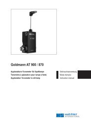
BX 900 ®<br />
PHOTO SLIT LAMP<br />
<strong>Slit</strong> <strong>Lamp</strong> <strong>Imaging</strong> <strong>Guide</strong>
Preamble<br />
On August 3 rd , 1911, Alvar Gullstrand introduced the first rudimentary model of the slit lamp<br />
illuminator.<br />
An occasion of tremendous significance to ophthalmology had just taken place. Gullstrand<br />
described a device with the potential to advance the understanding of the eye and its problems as<br />
profoundly as did the direct ophthalmoscope 50 years earlier. By 1916, Henker had developed a<br />
practical combination of Gullstrand's illuminator and Czapski's corneal microscope, marking the<br />
first major advance in methods of examining the external eye in more than a century. In 1936<br />
Comberg established the co-pivotal and iso-centric relationship between the microscope and slit<br />
illuminator and, in 1938, Goldmann’s collaboration with <strong>Haag</strong>-<strong>Streit</strong> produced the first par-focal<br />
instrument which also featured the single control lever design in use to this day. Goldmann also<br />
influenced the shift to Köhler illumination, greatly improving the efficiency of the slit lamp illuminator,<br />
the very heart of this marvelous device.<br />
These significant milestones, with contributions from<br />
a host of other individuals, have coalesced into the highly sophisticated instruments that are placed<br />
at our disposal today. In light of such capabilities in instrumentation, it follows that our results in<br />
slit lamp examination and slit lamp photography will rest on the level of sophistication we apply<br />
to the practice of these challenging and stimulating art forms.<br />
Csaba L. Mártonyi, COPRA, CRA<br />
Emeritus Associate Professor<br />
University of Michigan, Ann Arbor<br />
BX User <strong>Guide</strong><br />
This guide is intended to assist all those who seek to capture images of the eye using the slit<br />
lamp to improve the quality of their photography by using simple to follow illumination diagrams<br />
and high quality image examples. We hope this book provides inspiration and motivation<br />
to anyone who is involved the art of documenting the unique properties and pathologies<br />
of the eye and through <strong>Haag</strong>-<strong>Streit</strong> we offer a number of instruments to help you.<br />
The <strong>Haag</strong>-<strong>Streit</strong> BX900 slit lamp marries the latest imaging technology with the proven versatility,<br />
optical brilliance and build quality of the <strong>Haag</strong>-<strong>Streit</strong> tradition. The BX900 is the leading<br />
slit lamp-imaging device that is designed to assist the Ophthalmic Photographer with his<br />
demanding job. Furthermore it will also provide a valuable asset for all Eye Cap Specialists who<br />
demand the highest clinical and educational standards.<br />
<strong>Haag</strong>-<strong>Streit</strong> greatly appreciates and thanks all those who have contributed to this publication<br />
with special thanks to Cees van Beek of Leyenburg Hospital, Den <strong>Haag</strong> who provided many of<br />
the images.<br />
Steve Thomson<br />
<strong>Haag</strong>-<strong>Streit</strong> AG
CONTENTS<br />
BX900 ® PHOTO SLIT LAMP 4<br />
TECHNICAL DATA 6<br />
PHYSICAL AND OPTICAL CONDITIONS 7<br />
TYPES OF ILLUMINATION 7<br />
STANDARD SETTING 8<br />
ILLUMINATION AND EXPOSURE SETTINGS 8<br />
PICTOGRAMS 8<br />
OVERVIEW 9<br />
LIDS 10<br />
CONJUNCTIVA 10<br />
CORNEA 11<br />
ANTERIOR CHAMBER, CHAMBER ANGLE 14<br />
IRIS, IRIS-ANGIOGRAPHY 15<br />
LENS 16<br />
VITREOUS 17<br />
FUNDUS 18
4<br />
BX 900 ® PHOTO SLIT LAMP<br />
3<br />
1<br />
8<br />
12<br />
The <strong>Haag</strong>-<strong>Streit</strong> Photo-<strong>Slit</strong> <strong>Lamp</strong> BX 900 ® is based on the <strong>Slit</strong> <strong>Lamp</strong> BQ 900 ® . It is therefore possible<br />
to use the same instrument both for ocular examination and documentation. A photo-slit<br />
lamp is a combination of a biomicroscope, and illumination system and the photo attachment.<br />
The Photo-<strong>Slit</strong> <strong>Lamp</strong> BX 900 ® and the <strong>Slit</strong> <strong>Lamp</strong> BQ 900 ® share the same microscope. The illumination<br />
system of the photo-slit lamp has in addition a flash unit and a background illumination.<br />
Two different light sources are available: the flash illumination and the modelling light. On<br />
the following page the different components will be explained.<br />
2<br />
4<br />
5<br />
6<br />
7<br />
9<br />
11<br />
10<br />
1. Cable guide<br />
2. Flash housing<br />
3. Flash intensity changer<br />
for background illumination<br />
4. Objective tube<br />
5. Camera body<br />
6. Eye-piece with double cross<br />
hair reticle<br />
7. Mirror housing<br />
8. Background illumination<br />
9. Mirror and Diffusion filter<br />
10. Cold light source<br />
11. Shutter release bar<br />
12. Photo control unit
1. The cable guide contains the high voltage cable for the<br />
flash light.<br />
2. The flash housing contains the flash tube. Firing the BX900<br />
trigger will simultaneously deliver a flash through the illumination<br />
system and, via a glass fibre cable, the fill background<br />
illumination while synchronising with the camera<br />
shutter.<br />
3. The background illumination changer has seven settings:<br />
= 100 % = 50% = 25%<br />
= 10% = 5% = 0% = blue filter<br />
These selections are only for the fill flash of the background<br />
illumination. The modelling light is controlled by the cold<br />
light source.<br />
4. The camera body is mounted on the top of the biomicroscope<br />
allowing full visibility of the patient’s eyes from either side of<br />
the microscope. Not all cameras available on the market can<br />
be used. <strong>Haag</strong>-<strong>Streit</strong> has selected a number of models and has<br />
made the necessary adaptations. The correct function of the<br />
photo-slit lamp is guaranteed only by the use of cameras that<br />
are recommended by <strong>Haag</strong>-<strong>Streit</strong>. A list of current camera<br />
models is available at: www.haag-streit.com. Note that<br />
the camera has to be in the «MANUAL» operating mode and<br />
the shutter speed should be set to 1/90 sec. The recommended<br />
ISO rating for general use is 200 and colour temperature of<br />
the flash is 6000k but users have the option to apply other<br />
setting as required.<br />
5. The 12.5x eyepiece with double cross hair reticule is inserted<br />
into the right ocular of the microscope. This must be correctly<br />
focused for the user’s eye to ensure sharp images are captured.<br />
Note that this setting is not the user’s refractive error.<br />
6. The principal component of the <strong>Haag</strong>-<strong>Streit</strong> Photo-<strong>Slit</strong> <strong>Lamp</strong><br />
BX 900 ® is the mirror housing with its built-in diaphragms.<br />
It mounts between the magnification changer and the binocular<br />
tube. When capturing an image all light is directed, via<br />
a mirror, to the camera. This allows the maximum utilisation<br />
of the available light: 100% for the examination and 100% for<br />
the image. The built-in diaphragm setting with five apertures<br />
is applied automatically on image capture. For the aperture<br />
intervals: Step 1 = largest aperture, Step 5 = smallest aperture.<br />
The small knobs on each side of the mirror housing can be<br />
used during examination to quickly activate the diaphragms<br />
to the pre-set position. This allows a preview prior to capture<br />
so that the image subject and depth of field may be checked.<br />
7. The background illumination is swivel-mounted on a horizontal<br />
level and is illuminated through two glass fibre cables.<br />
The flash fill light comes from the flash housing and the modelling<br />
light comes from the cold light source. The modelling<br />
light is used to show where any reflection of the fill flash will<br />
fall.<br />
8. The cold light source is mounted under the table and it provides<br />
the background modelling illumination.<br />
9. With the diffusion filter the slit beam can be covered allowing<br />
overview pictures with diffuse illumination.<br />
10. The shutter release bar is conveniently positioned in front of<br />
the joystick on the cross-slide. It can be used either right or<br />
left-handed.<br />
11. The photo control unit is mounted under the left hand side of<br />
the table and has the main switch for the power supply. On<br />
the front side there are two switches and four error light indicators.<br />
With the main power switch it is possible to turn off<br />
the entire electrical system of the slit lamp. The camera may<br />
be turned off separately. The power switch on the front side<br />
is only for the photo control unit. With the flash-intensity<br />
switch in the high position, the flash light increases by one<br />
aperture step. Optical and acoustic warning signals will be<br />
activated in the case of an error when the shutter release bar<br />
is pressed. Once the cause of the problem has been removed,<br />
press the shutter release bar and the optical warning signal<br />
will be cancelled and the camera will be ready for use.<br />
5
6<br />
TECHNICAL DATA<br />
BIOMICROSCOPE<br />
Magnification Changer 6.3 x 10 x 16 x 25 x 40 x<br />
Ocular Magnification 12.5 x<br />
Range of Adjusting Oculars +8 to -8 dioptres<br />
Reticle right ocular<br />
Inter-pupillary Distance 52–78 mm<br />
SLIT LAMP ILLUMINATOR<br />
<strong>Slit</strong> Height 1– 8 mm<br />
<strong>Slit</strong> Width 0–8 mm<br />
Spotlight 0.2, 1, 2, 3, 5, 8 mm diameter<br />
Horizontal Arc +/- 90°<br />
Vertical Arc 5°, 10°, 15°, 20°<br />
Filters blue, green (red free), N. D. 10%<br />
<strong>Slit</strong> Beam Diffuser yes<br />
Light Source Illumination Device 6V 4.5A Tungsten<br />
Light Source Background Illumination Halogen<br />
PHOTO ATTACHMENT<br />
Image Delivery Quick Return Mirror 100 % light for examination or<br />
photography<br />
Objective Tube Focal Length 170 mm<br />
Light Source Flash Light normal 200 Ws, high 400 Ws<br />
DEPTH OF FIELD<br />
dependent on magnification and aperture<br />
Magnification Extent of depth of focus (+/- in mm)<br />
with aperture<br />
1 2 3 4 5<br />
6.3 x 1.3 1.8 2.6 3.6 5.2<br />
10 x 0.5 0.7 1 1.4 2<br />
16 x 0.2 0.3 0.4 0.5 0.8<br />
25 x 0.1 0.1 0.15 0.2 0.3<br />
40 x 0.05 0.05 0.05 0.1 0.15<br />
Values will be increased by 35% in transparent media of the eyes<br />
IMAGE AND MAGNIFICATION DATA<br />
Setting at<br />
magnification<br />
changer<br />
Chip dimensions<br />
Magnification<br />
in<br />
plane of<br />
the chip<br />
Size of field<br />
in mm<br />
24x36 mm<br />
Mono<br />
Circles: visible field of the eye-piece<br />
15x22.5 mm<br />
Mono<br />
Magnification<br />
in<br />
plane of<br />
the chip<br />
24x36 mm<br />
Stereo<br />
6.3 x 0.63x 38x57 23.8x35.7 0.63x 38x28.5<br />
10 x 1x 24x36 15x22.5 1x 24x18<br />
16 x 1.6x 15x22.5 9.4x14.1 1.6x 15x11<br />
25 x 2.5x 9.5x14 6x9 2.5x 3.5x7<br />
40 x 4x 6x9 3.88x5.6 4x 6x4.5
PHYSICAL AND OPTICAL CONDITIONS<br />
The binocular examination of the eyes with the slit lamp takes<br />
place in a three-dimensional space with great depth of field.<br />
Normal slit lamp imaging is a two-dimensional documentation<br />
with a very small depth of field. The difference between<br />
stereo viewing and monocular imaging can sometimes prove<br />
troublesome. However, viewing monocularly can help. Note<br />
only the image through the right eyepiece is recorded.<br />
The photographer’s view through the eyepieces is not the same<br />
as the recorded image. Through the eyepieces a circular image is<br />
visible whereas the image captured is rectangular (see page 6).<br />
The <strong>Haag</strong>-<strong>Streit</strong> BX900 has no measurements for the lightintensity<br />
and no automatic exposure system. It is therefore useful<br />
to take notes in the early stages of using the BX. Downloading<br />
images into EyeCap or a suitable image viewer will<br />
enable instant evaluation and will enable adjustments to be<br />
made that optimise the image. The practical examples will help,<br />
but they are only starting-points.<br />
TYPES OF ILLUMINATION<br />
The correct illumination will allow optimal recording of ocular<br />
pathology.<br />
DIFFUSE ILLUMINATION<br />
The slit lamp beam should be completely opened and covered<br />
by the diffusing filter. The background illumination can be used<br />
in conjunction with the slit illumination for more uniform lighting.<br />
The diffuse illumination is normally used for overview pictures<br />
with low magnification (10x and 16x).<br />
DIRECT FOCAL ILLUMINATION<br />
Direct focal illumination refers to projecting the light on the<br />
subject at the plane of focus. Unlike diffused light concentrated<br />
light penetrates transparent structures. With a centred slit<br />
beam there is always direct focal illumination.<br />
INDIRECT ILLUMINATION<br />
With indirect illumination the light does not fall directly on the<br />
pathology. The slit beam is decentred and projected just adjacent<br />
to the subject area and it is illuminated by scattered internally<br />
reflected light.<br />
The BX900 has a clear screen with a cross hair reticule. The<br />
accommodative abilities of the photographer’s own eye are<br />
normally not noticeable during an examination: It is important<br />
that the photographer must establish the correct eye-piece setting<br />
(see page 5) to neutralise any accommodation. Only by<br />
viewing a sharp image of the reticule overlying a focused image<br />
of the eye will sharply focused images be captured.<br />
It should also be considered that the examiner’s attention is<br />
focused on the details that are of interest and by selective viewing<br />
the brain suppresses certain artefacts. The camera however<br />
does not!<br />
RETROILLUMINATION<br />
Retroillumination is an indirect illumination too. Light reflected<br />
from the fundus or iris illuminates the pathology from<br />
behind. If the slit beam is decentred and higher magnification<br />
is used, unwanted reflections can be minimised.<br />
PHOTOGRAPHY WITH THREE-MIRROR CONTACT<br />
LENS OR 90-DIOPTER LENS<br />
With these instruments there are more optical interfaces (air /<br />
glass and glass / cornea). All interfaces cause reflexes and<br />
therefore it is better to take images without the background<br />
illumination. Furthermore any scratches or damage to the lens<br />
will increase the number of image artefacts.<br />
If the space between the diagnostic contact lens and the slit illuminator<br />
is very small, the background illumination can be<br />
locked in the centre position.<br />
7
8<br />
STANDARD SETTING<br />
The BX900 has many different adjustments and its correct use<br />
can give optimal illumination and exposure. It is advantageous<br />
to always start with a standard setting and to make adjustments<br />
after each image captured.<br />
An example for a standard setting is the diffuse illumination:<br />
1. Main switch on, photo control unit POWER ON and<br />
camera body on.<br />
2. After waiting a few seconds, set the flash intensity on HIGH.<br />
3. 100% Background illumination<br />
45°Angle between microscope and background illumination<br />
<strong>Slit</strong> beam vertical<br />
Background<br />
Illumination:<br />
<strong>Slit</strong> Beam with<br />
Diffused Filter:<br />
Wide <strong>Slit</strong> Beam:<br />
Moderate <strong>Slit</strong><br />
Beam:<br />
Narrow <strong>Slit</strong><br />
Beam:<br />
<strong>Slit</strong> beam fully open (slit width and height)<br />
<strong>Slit</strong> beam centred (screw tightened)<br />
100% slit illumination (without filter)<br />
<strong>Slit</strong> beam covered with the diffusion filter<br />
Angle between microscope and illumination device 30°–45°<br />
Magnification 10x<br />
Aperture 4 with a sensor rating ISO 200<br />
4. Define the image field, close the left eye (note the difference<br />
between eye-piece and photo tube picture)<br />
5. Focus control (eye-piece setting correct?)<br />
6. Capture Image.<br />
ILLUMINATION AND EXPOSURE SETTINGS<br />
The following table shows the different settings of illumination<br />
and exposure adjustments. This table is also used for practical<br />
examples and will give a starting point.<br />
PICTOGRAMS<br />
ISO: 200<br />
Flash Intensity: high / normal<br />
Background: 100%, 50%, 25%, 10%, 0%, blue filter<br />
Angle: 0° – 90°<br />
<strong>Slit</strong> Beam: 0 (= closed) to 8 mm (= full open)<br />
Filter: blue, red free (green), grey (10% N. D.), diffused<br />
Angle: 0° – 90°<br />
Magnification: 10x 16x 25x 40x<br />
Aperture: 1 – 5 1 – 5 1 – 5 1 – 5<br />
<strong>Slit</strong> Beam<br />
Centered:<br />
<strong>Slit</strong> Beam<br />
Decentered:<br />
Microscope:
OVERVIEW<br />
DIFFUSE ILLUMINATION WITH SLIT ILLUMINATION AND BACKGROUND ILLUMINATION<br />
The diffuse illumination with slit beam and background illumination gives a shadowfree<br />
illumination with natural colours and two light reflexes. This is most useful for<br />
low magnification overview images.<br />
DIFFUSE ILLUMINATION WITH BACKGROUND ILLUMINATION ONLY<br />
The diffuse illumination with only the background illumination increases the contrast.<br />
The structures of the iris are more visible and there is only one light reflex.<br />
9<br />
ISO: 200<br />
Flash Intensity: high<br />
Background: 100%<br />
Angle: 30°–45°<br />
<strong>Slit</strong> Beam: fully open<br />
Filter: diffused<br />
Angle: 30°<br />
Magnification: 10x 16x 25x 40x<br />
Aperture: 4 4 3 2<br />
ISO: 200<br />
Flash Intensity: high<br />
Background: 100%<br />
Angle: 30°–45°<br />
<strong>Slit</strong> Beam: closed<br />
Filter: –<br />
Angle: –<br />
Magnification: 10x 16x 25x 40x<br />
Aperture: 4 3 3 2
10<br />
LIDS<br />
DIFFUSE ILLUMINATION<br />
Diffuse illumination provides evenly balanced lighting. ISO: 200<br />
Flash Intensity: low<br />
Background: 50%<br />
Angle: 30°–45°<br />
<strong>Slit</strong> Beam: fully open<br />
Filter: diffused<br />
Angle: 30°<br />
Magnification: 10x 16x 25x 40x<br />
Aperture: 4 4 3 2<br />
CONJUNCTIVA<br />
DIFFUSE ILLUMINATION<br />
Diffuse illumination provides evenly balanced lighting. Exposure control is more<br />
varied due to increased reflectivity.<br />
NARROW SLIT<br />
A centred, narrow slit beam projected at a 45° angle demonstrates surface topography<br />
and trans-illumination of the lesion. The background illumination gives the position<br />
of the slit beam.<br />
ISO: 200<br />
Flash Intensity: low<br />
Background: 50%<br />
Angle: 30°–45°<br />
<strong>Slit</strong> Beam: fully open<br />
Filter: diffused<br />
Angle: 30°<br />
Magnification: 10x 16x 25x 40x<br />
Aperture: 5 5 4 3<br />
ISO: 200<br />
Flash Intensity: high<br />
Background: 25%<br />
Angle: 30°–45°<br />
<strong>Slit</strong> Beam: 0.1 mm<br />
Filter: –<br />
Angle: 45°<br />
Magnification: 10x 16x 25x 40x<br />
Aperture: 3 2 2 1
INDIRECT ILLUMINATION<br />
A moderately wide and decentred slit beam is projected just adjacent to the border of<br />
the lesion. The light penetrates conjunctiva and illuminates the clear fluid below. In<br />
the presence of blood or scar tissue, the light is absorbed.<br />
CORNEA<br />
DIFFUSE ILLUMINATION<br />
This illumination technique can only be used in the presence of dense corneal pathologies<br />
because diffuse light does not penetrate very well through the cornea. Dilating<br />
the pupil can enhance pathology by creating a darker background.<br />
WIDE SLIT BEAM – TANGENTIAL ILLUMINATION<br />
This technique can provide more information as the oblique illumination is reflected<br />
and refracted by the cornea and any pathology. Experiment with the illumination angle<br />
slit beam width for optimum results.<br />
11<br />
ISO: 200<br />
Flash Intensity: high<br />
Background: 10%<br />
Angle: 30°–45°<br />
<strong>Slit</strong> Beam: 2–4 mm<br />
Filter: –<br />
Angle: decentred<br />
Magnification: 10x 16x 25x 40x<br />
Aperture: 2 2 1 1<br />
ISO: 200<br />
Flash Intensity: high<br />
Background: 100%<br />
Angle: 30°–45°<br />
<strong>Slit</strong> Beam: fully open<br />
Filter: diffused<br />
Angle: 30°<br />
Magnification: 10x 16x 25x 40x<br />
Aperture: 4 4 3 2<br />
ISO: 200<br />
Flash Intensity: high<br />
Background: 0%–25%<br />
Angle: 45°<br />
<strong>Slit</strong> Beam: open<br />
Filter: 10%<br />
Angle: 60°–80°<br />
Magnification: 10x 16x 25x 40x<br />
Aperture: – 4 3 2
12<br />
MODERATE SLIT BEAM WITH SEPARATION OF ILLUMINATED EPITHELIUM AND ENDOTHELIUM<br />
The moderate beam produces two different layers of illumination, one on the<br />
epithelium and one on the endothelium. Note the corneal changes are closer to<br />
the posterior reflection and therefore they lie deep in the cornea.<br />
NARROW SLIT BEAM – OPTICAL SECTIONING<br />
A narrow focal slit beam is projected at a 45° to 60° angle. It cuts an optical section<br />
through the cornea like a knife. With this technique it is possible to locate the layer<br />
of the pathological changes. These examples demonstrate endothelial and surface<br />
pathology.<br />
DIRECT RETROILLUMINATION FROM THE IRIS<br />
A moderate slit beam is decentred and angled to project onto the iris directly behind<br />
the pathology. The light reflects and backlights the cornea. If there is some cataract<br />
present the lens can also be used to reflect light directly onto the area of interest.<br />
ISO: 200<br />
Flash Intensity: high<br />
Background: 0%–25%<br />
Angle: 30°<br />
<strong>Slit</strong> Beam: 2–3 mm<br />
Filter: –<br />
Angle: 45°<br />
Magnification: 10x 16x 25x 40x<br />
Aperture: – 3 3 2<br />
ISO: 200<br />
Flash Intensity: high<br />
Background: 0–10%<br />
Angle: 45°<br />
<strong>Slit</strong> Beam: 0.1 mm<br />
Filter: –<br />
Angle: 45°–60°<br />
Magnification: 10x 16x 25x 40x<br />
Aperture: – 1 1 –<br />
ISO: 200<br />
Flash Intensity: high<br />
Background: 0%<br />
Angle: –<br />
<strong>Slit</strong> Beam: 1–2 mm<br />
Filter: –<br />
Angle: decentred<br />
Magnification: 10x 16x 25x 40x<br />
Aperture: – 2 1 1
INDIRECT RETROILLUMINATION FROM THE IRIS<br />
The moderate slit beam is now decentred even more and angled to project onto the<br />
iris adjacent to the area behind the area of interest. The background is dark and the<br />
edges of non-pigmented lesions are well defined by the diffuse light reflecting from<br />
the iris.<br />
SCLEROTIC SCATTER<br />
The wide decentred slit beam is projected onto the limbus. The light striking the limbus<br />
is internally reflected through the corneal tissue like a fibre optic. Corneal changes<br />
or abnormalities can be visualised by reflecting the scattered light. Careful post capture<br />
cropping can enhance images.<br />
TOPICAL ADMINISTRATION OF SODIUM FLUORESCEIN<br />
Sodium fluorescein is applied gently to the bulbar conjunctiva. The patient should<br />
blink once or twice for the dye to be dispersed over the eye. If the epithelium of the<br />
conjunctiva or the cornea is damaged, the fluorescein stains the underlying tissue. The<br />
remaining dye fluoresces a yellow green colour when excited by the blue light. Healthy<br />
epithelium does not stain.<br />
Rose Bengal is a dye that can be used to demonstrate abnormal epithelial cells. The<br />
dye is applied like sodium fluorescein and is usually imaged using direct white light.<br />
13<br />
ISO: 200<br />
Flash Intensity: high<br />
Background: 0–10%<br />
Angle: –<br />
<strong>Slit</strong> Beam: 1–2 mm<br />
Filter: –<br />
Angle: decentred<br />
Magnification: 10x 16x 25x 40x<br />
Aperture: – 2 1 1<br />
ISO: 200<br />
Flash Intensity: high<br />
Background: 0%<br />
Angle: –<br />
<strong>Slit</strong> Beam: 2 mm<br />
Filter: –<br />
Angle: decentred<br />
Magnification: 10x 16x 25x 40x<br />
Aperture: – 2 1 1<br />
ISO: 200<br />
Flash Intensity: high<br />
Background: blue filter<br />
Angle: 30°<br />
<strong>Slit</strong> Beam: fully open<br />
Filter: blue filter<br />
Angle: 60°–80°<br />
Magnification: 10x 16x 25x 40x<br />
Aperture: 3 3 2 1
14<br />
ANTERIOR CHAMBER, CHAMBER ANGLE<br />
AQUEOUS FLARE – TYNDALL’S PHENOMENON<br />
Cells, pigment or proteins in the aqueous humour reflect the light like a faint fog. To<br />
visualise this the slit illuminator is adjusted to the smallest circular beam and is projected<br />
through the anterior chamber from a 42° to 90° angle. The strongest reflection<br />
is possible at 90°.<br />
CHAMBER ANGLE – GONIOPHOTOGRAPHY<br />
The desired mirror of the gonioscopy lens is positioned opposite to the area of pathology.<br />
A wide slit beam is projected in the desired mirror from a near coaxial position to<br />
the biomicroscope. Light reflections can be eliminated by tilting the lens.<br />
ISO: 200<br />
Flash Intensity: high<br />
Background: 0%–25%<br />
Angle: 30°<br />
<strong>Slit</strong> Beam: 0.1–1 mm<br />
Filter: –<br />
Angle: 50°<br />
Magnification: 10x 16x 25x 40x<br />
Aperture: – 1 1 1<br />
ISO: 200<br />
Flash Intensity: high<br />
Background: 0%<br />
Angle: –<br />
<strong>Slit</strong> Beam: 2 mm<br />
Filter: –<br />
Angle: 10°<br />
Magnification: 10x 16x 25x 40x<br />
Aperture: – 5 5 4
IRIS, IRIS-ANGIOGRAPHY<br />
WIDE SLIT BEAM - TANGENTIAL ILLUMINATION<br />
The wide slit beam is projected at an oblique angle of 80° – 90° onto the iris. This illumination<br />
creates strong shadows and the surface texture is enhanced. If the headrest<br />
doesn’t allow a wide oblique angle it is sometimes necessary to turn the patient’s head<br />
a little away from the light.<br />
IRIS TRANSILLUMINATION<br />
The slit illuminator is positioned coaxially to the biomicroscope and adjusted to provide<br />
a small circular beam of light. This beam is projected through the pupil which<br />
should be at mid dilation. The light reflects from the fundus and backlights the iris.<br />
Normally the iris pigment absorbs the light, but pigmentation defects let the red fundus<br />
light pass through..<br />
IRIS ANGOIGRAPHY<br />
The illumination technique of the iris angiography is like the tangential illumination<br />
with the background illumination opposite the slit beam. Both slit illuminator and<br />
background illumination have a blue excitation filter. The yellow barrier filter is positioned<br />
between the magnification changer and the mirror housing. The barrier filter<br />
only works on the image from the right eyepiece which is directed to the camera. Control<br />
of the focus of the image during the angiography is possible through the left eyepiece.<br />
15<br />
ISO: 200<br />
Flash Intensity: high<br />
Background: 0%–10%<br />
Angle: 45°<br />
<strong>Slit</strong> Beam: open<br />
Filter: –<br />
Angle: 80°<br />
Magnification: 10x 16x 25x 40x<br />
Aperture: 5 5 4 4<br />
ISO: 200<br />
Flash Intensity: high<br />
Background: 0%–10%<br />
Angle: 45°<br />
<strong>Slit</strong> Beam: Ø 1–2 mm<br />
Filter: –<br />
Angle: coaxial<br />
Magnification: 10x 16x 25x 40x<br />
Aperture: – 2 1 1<br />
ISO: 800<br />
Flash Intensity: high<br />
Background: blue filter<br />
Angle: 45°<br />
<strong>Slit</strong> Beam: open<br />
Filter: blue filter<br />
Angle: 45°–60°<br />
Magnification: 10x 16x 25x 40x<br />
Aperture: – 1 – –
16<br />
LENS<br />
NARROW SLIT BEAM – OPTICAL SECTIONING<br />
A narrow focal slit beam is projected at a 45° angle to the lens as an optical section is<br />
made. Because of the problematic depth of field it is not possible to photograph the<br />
entire lens section in focus. It is therefore necessary to focus on the anterior or the posterior<br />
lens surface.<br />
MODERATE SLIT BEAM – DIRECT ILLUMINATION<br />
A moderate slit beam is projected at a 45° angle to the lens pathology and is directly<br />
illuminated. Dilation of the pupil is required for effective imaging.<br />
MODERATE SLIT BEAM – TANGENTIAL ILLUMINATION<br />
A moderate to wide slit beam is projected at an angle greater then 45 degrees to provide<br />
oblique tangential illumination that can enhance detail by providing shadows.<br />
Pupil dilation will aid this illumination technique.<br />
ISO: 200<br />
Flash Intensity: high<br />
Background: 25%<br />
Angle: 45°<br />
<strong>Slit</strong> Beam: 0.1 mm<br />
Filter: –<br />
Angle: 45°<br />
Magnification: 10x 16x 25x 40x<br />
Aperture: – 1 1 –<br />
ISO: 200<br />
Flash Intensity: high<br />
Background: 10%<br />
Angle: 45°<br />
<strong>Slit</strong> Beam: 2–4 mm<br />
Filter: –<br />
Angle: 45°<br />
Magnification: 10x 16x 25x 40x<br />
Aperture: – 2 2 1<br />
ISO: 200<br />
Flash Intensity: high<br />
Background: 10%<br />
Angle: 45–60°<br />
<strong>Slit</strong> Beam: 2–6 mm<br />
Filter: –<br />
Angle: 45°–60°<br />
Magnification: 10x 16x 25x 40x<br />
Aperture: – 2 2 1
RETROILLUMINATION FROM THE FUNDUS – RED-REFLEX PHOTOGRAPHY<br />
The slit illuminator is positioned in an almost coaxial position with the biomicroscope.<br />
Awide slit beam is decentered and adjusted to a half circle by using the slit width and<br />
height controls. The decentred slit beam is projected near the pupil margin through a<br />
dilated pupil. Careful composition can minimise the direct reflection.<br />
VITREOUS<br />
NARROW SLIT BEAM<br />
Without diagnostic lenses it is only possible to examine and to document the anterior<br />
part of the vitreous. Anterior Vitreous pathology can be seen with a narrow slit beam.<br />
Only when the dioptric power of the eye is reduced is it possible to focus more<br />
posteriorly.<br />
17<br />
ISO: 200<br />
Flash Intensity: high<br />
Background: 0%<br />
Angle: –<br />
<strong>Slit</strong> Beam: 2 mm<br />
Filter: –<br />
Angle: decentred<br />
Magnification: 10x 16x 25x 40x<br />
Aperture: – 2 1 1<br />
ISO: 200<br />
Flash Intensity: high<br />
Background: 0%–10%<br />
Angle: 45°<br />
<strong>Slit</strong> Beam: 0.1–1.0 mm<br />
Filter: –<br />
Angle: 45°<br />
Magnification: 10x 16x 25x 40x<br />
Aperture: – 1 1 –
18<br />
FUNDUS<br />
CENTRAL RETINA PHOTOGRAPHS WITH THE THREE-MIRROR CONTACT LENS<br />
The posterior pole can be documented with the centre of the three-mirror contact lens.<br />
The slit lamp illuminator is in an almost coaxial position. If the slit beam is too wide<br />
disturbing light reflections may occur.<br />
CENTRAL RETINA PHOTOGRAPHS WITH A 90-DIOPTER LENS<br />
Diagnostic contact lenses are sometimes contraindicated after intra-ocular surgery. In<br />
such cases the use of the 90- dioptre lens is necessary. The handling of this lens is more<br />
difficult because there is no physical contact with the eye. A moderate slit beam in the<br />
almost coaxial position gives the best results.<br />
ISO: 200<br />
Flash Intensity: high<br />
Background: 0%<br />
Angle: –<br />
<strong>Slit</strong> Beam: 2 mm<br />
Filter: 10%<br />
Angle: 5°–10°<br />
Magnification: 10x 16x 25x 40x<br />
Aperture: – 2 1 1<br />
ISO: 200<br />
Flash Intensity: high<br />
Background: 0%<br />
Angle: –<br />
<strong>Slit</strong> Beam: 2 mm<br />
Filter: 10%<br />
Angle: 5°–10°<br />
Magnification: 10x 16x 25x 40x<br />
Aperture: – 2 1 –
Recommended Reading<br />
Clinical <strong>Slit</strong> <strong>Lamp</strong> Biomicroscopy and<br />
Photo <strong>Slit</strong> <strong>Lamp</strong> Biomicrography<br />
Martonyi, Bahn & Meyer<br />
Time One Ink, Ltd.<br />
Sedona, AZ<br />
This book is currently in revision.<br />
An expanded Third Edition is<br />
expected late 2005.<br />
Copies of the Third Edition and other books<br />
of interest to the Ophthalmic Photographer can<br />
be found at;<br />
http://www.twinchimney.com<br />
Photos by:<br />
Cees van Beek<br />
Leyenburg Hospital, Den <strong>Haag</strong>, Netherlands<br />
Tarek Shaarawy<br />
University Hospiral of Geneva, Switzerland<br />
Steve Thomson<br />
<strong>Haag</strong>-<strong>Streit</strong>, Bern, Switzerland
HAAG-STREIT AG<br />
Gartenstadtstrasse 10<br />
CH-3098 Koeniz/Switzerland<br />
Phone ++41 31 978 01 11<br />
Fax ++41 31 978 02 82<br />
info@haag-streit.ch<br />
www.haag-streit.com<br />
1500.7200668.02000 / 09.05-2.5