Info RASCHIG-JAEGER Tray Technology-401
Info RASCHIG-JAEGER Tray Technology-401
Info RASCHIG-JAEGER Tray Technology-401

Create successful ePaper yourself
Turn your PDF publications into a flip-book with our unique Google optimized e-Paper software.
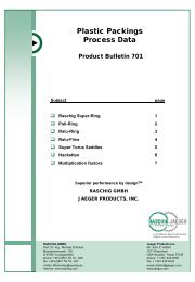
Fractination <strong>Tray</strong>s<br />
Product Bulletin <strong>401</strong><br />
For many years, column trays have been used in a wide range of<br />
separation p pprocesses in the ppetrochemical<br />
and chemical industries.<br />
Although trays have been replaced in part by random and structured<br />
packing, there are many mass transfer applications in which trays will<br />
be the preferred choice. <strong>Tray</strong>s are essentially used when:<br />
� Towers are very large in diameter (Multi-pass <strong>Tray</strong>s)<br />
� Compounds contain solids or foulants<br />
� There are many internal transitions<br />
�� Liquid loads are high<br />
� Lack of experience in the service<br />
� Chemical Reaction/Absorption - use high weirs to provide greater<br />
residence time for absorption / chemical reaction.<br />
The Raschig Jaeger Group offers a variety of tray products which<br />
include conventional sieve, valve and bubble cap trays, and specialty<br />
trays such as dual flow trays, Nye trays, disc and donut and side-to-<br />
side baffle trays trays.<br />
Superior performance by design TM<br />
<strong>RASCHIG</strong> GMBH<br />
<strong>JAEGER</strong> PRODUCTS, INC.<br />
in die Eckbegrenzungen<br />
(Größe 12,6 x 7,8 mm)<br />
kommt ein Foto
Table of contents<br />
Subject page<br />
� Conventional <strong>Tray</strong>s 1<br />
Sieve <strong>Tray</strong>s 2<br />
Valve <strong>Tray</strong>s 3<br />
Movable Float Valve (RJ-V1 / RJ-V4) 4<br />
Fixed Valve (RJ-V0 / RJ-SVG / RJ-MV) 7<br />
Caged Float Valve (RJ-A1 / RJ-A2 / RJ-A3) 12<br />
Bubble Cap <strong>Tray</strong>s<br />
� Specialty p y <strong>Tray</strong>s y<br />
16<br />
Dual Flow <strong>Tray</strong>s 18<br />
Nye <strong>Tray</strong>s 19<br />
Baffle <strong>Tray</strong>s / Disc&Donut <strong>Tray</strong>s 21<br />
� Comparison of Conventional <strong>Tray</strong> Types 22<br />
�� Summary of <strong>Tray</strong> Geometries 23<br />
� Contact 26
Active<br />
Area<br />
Flow Path<br />
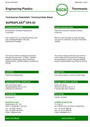
Conventional <strong>Tray</strong>s<br />
Conventional trays are cross flow trays. Liquid descending<br />
from the tray above emerges from the inlet downcomer and<br />
flows across a rapidly diverging/converging open channel or<br />
tray active area to the outlet downcomer. Vapour from the tray<br />
below is forced through the active area into the cross flowing<br />
liquid to produce a two-phase mixture of aerated liquid. The<br />
nature of the aerated liquid is dependant upon the relative<br />
vapour and liquid velocities and the vapour-liquid contact<br />
openings on the tray active area.<br />
Below is a simple sketch of a single-pass cross flow tray.<br />
Two- or four-pass trays are used when the liquid load is much<br />
higher.<br />
Downcomer<br />
Seal Area<br />
i<br />
Outlet<br />
Downcomer<br />
Downcomer<br />
Clearance<br />
Active<br />
Area<br />
Outlet<br />
Weir<br />
1
Sieve <strong>Tray</strong>s<br />
Sieve trays became a dominate tower internal for mass<br />
transfer columns in the 1950’s owing to their simple shape and<br />
ease of manufacture. This made sieve trays a popular device<br />
for extensive research and as a result, a considerable amount<br />
of experience has been gained for tray design and it’s<br />
application. Sieve trays are flat perforated plates in which<br />
vapour is forced through the holes into the cross flowing liquid.<br />
Vapour flow prevents liquid from leaking (weeping) through the<br />
holes. At low vapour velocities, liquid weeping through the<br />
holes occurs, which bypasses a portion of the tray active area<br />
and reduces efficiency, giving sieve trays relatively low<br />
turndown (approx (approx. 2-2 2 2.5:1). 5:1)<br />
The Raschig Jaeger Group has the capability to design and<br />
manufacture virtually any type of sieve tray. <strong>Tray</strong> hole sizes<br />
down to 3.2 mm in diameter are offered.<br />
in die Eckbegrenzungen<br />
(Größe 12,6 x 7,8 mm)<br />
kommt ein Foto<br />
2
Valve <strong>Tray</strong>s<br />
Like sieve trays, valve trays have been in use as far back as the<br />
1950’s but nowadays have become the more popular choice<br />
because of their greater operating range properties. Valve trays are<br />
essentially flat perforated trays with moveable or fixed valve units<br />
with or without a cage structure covering the holes. Moveable valves<br />
are disk-shaped type devices which are enclosed within a cage<br />
structure or contain legs formed out of the valve disk. Fixed valves<br />
are units with integral legs formed out of the tray deck.<br />
The open or vertical curtain area of the valve valve, through which vapour<br />
issues in a horizontal direction is defined by the restrictive legs<br />
integral with the valve unit or the leg-rise of the cage structure<br />
attached to the tray deck. As the vapour rate is increased, the valve<br />
units rise and the upper limit of opening is controlled by the valve leg<br />
height. It is at high vapour rates that valves serve to deflect<br />
entrainment first before propagating upwards unlike sieve trays.<br />
Upon decreasing the vapour rate, the curtain area of the valves<br />
decreases or valves settle intermittently over the holes. This<br />
minimizes liquid weeping while maintaining good operation at low<br />
flow rates. It is a combination of the above that permit valve trays to<br />
perform over a wider operating range and thus a higher turndown<br />
compared with sieve trays.<br />
The Raschig Jaeger Group can offer several types of valve units<br />
depending on the hydraulic loadings and the application.<br />
Movable valves: RJ-V1, RJ-V4<br />
Caged valves: RJ-A1, RJ-A3, RJ-A4<br />
Fixed Valve: RJ-V0, RJ-SVG, RJ-MV<br />
3
RJ-V1-Valve<br />
RJ-V1 Moveable Float Valve<br />
The RJ-V1 valve is a general purpose moveable float valve<br />
unit used in various services. The valve lid is normally 1.5 mm<br />
thick from which three restrictive legs are formed integrally.<br />
Various valve lifts are possible according to the leg rise. To<br />
improve the valve activity in certain cases trays are equipped<br />
with light and heavy valves.<br />
The valve unit contains anti-stick features with spacer tabs<br />
extending from the valve disk. When the valve unit is closed<br />
at low vapour rates, the spacer tabs provide a very narrow<br />
annular gap for vapour to escape radially into the cross flowing<br />
liquid. This promotes vigorous mixing while, at the same time,<br />
preventing the valve from sticking to the tray deck.<br />
The RJ-V1 also has anti-rotating features in that the tray<br />
orifices each have an extension from the tray floor. This<br />
prevents continuous rotation of valves and material wear.<br />
Flush seating and multiple weighted valves are optional.<br />
in die Eckbegrenzungen<br />
(Größe 12,6 x,8 mm)<br />
kommt ein Foto<br />
4
RJ-V1 Moveable Float Valve<br />
in die Eckbegrenzungen<br />
(Größe 12,6 x,8 mm)<br />
kommt ein Foto<br />
<strong>Tray</strong> with Moveable Valves (e.g. RJ-V1)<br />
5
RJ-V4-Valve<br />
RJ-V4 Moveable Float Valve<br />
The RJ-V4 valve is a low pressure drop general purpose unit<br />
in that the tray deck consists of a venturi-shaped orifice rather<br />
than a sharp-edge orifice. The venturi opening reduces<br />
significantly the pressure drop of the vapour at the deck entry<br />
and vertical curtain area. This leads to greater flexibility at<br />
lower vapour rates compared to that with a sharp-edge orifice.<br />
The RJ-V1 is used as the moveable float valve unit. It has the<br />
same restrictive legs bent downwards from the disk and antistick<br />
spacers.<br />
If desirable, flush seat and multiple weighted RJ-V4 valves are<br />
available.<br />
6
RJ-V0 Fixed Valve<br />
The RJ-V0 valve is a fixed unit punched out of the tray deck at<br />
a fixed vertical curtain distance. The valve consists of 6 legs<br />
formed integrally with the tray deck. The fixed nature of the<br />
valve unit implies an operating range flexibility similar to that<br />
for sieve trays. The main advantage of fixed valves is that the<br />
high horizontal vapour velocity issuing through the narrow<br />
curtain area promotes intense radial mixing with the crossflowing<br />
liquid and deflects entrainment sideways before being<br />
swept upwards. Furthermore the vapour flow creates a<br />
sweeping action along the tray floor which eliminates deposits<br />
of solid salts, and is therefore desirable for fouling<br />
applications applications. Also the RJ-V0 RJ V0 has no moving parts which<br />
makes it suitable for corrosive media.<br />
in die Eckbegrenzungen<br />
(Größe 12,6 x,8 mm)<br />
kommt ein Foto<br />
7
RJ-V0 Fixed Valve<br />
in die Eckbegrenzungen<br />
(Größe 12,6 x,8 mm)<br />
kkommt t ein i FFoto t<br />
<strong>Tray</strong> with Fixed Valves (e.g. RJ-V0)<br />
8
RJ-SVG Fixed Valve<br />
The RJ-SVG valve is a fixed unit punched out of the tray deck<br />
at a fixed vertical curtain distance. The valve consists of 2<br />
legs formed integrally with the tray deck. The fixed nature of<br />
the valve unit implies an operating range flexibility similar to<br />
that for sieve trays. The main advantage of fixed valves is<br />
that the high horizontal vapour velocity issuing through the<br />
narrow curtain area promotes intense radial mixing with the<br />
cross-flowing liquid and deflects entrainment sideways before<br />
being swept upwards. Furthermore the vapour flow creates a<br />
sweeping action along the tray floor which eliminates deposits<br />
of solid salts, and is therefore desirable for fouling<br />
applications applications. The advantage compared to the RJ-V0 RJ V0 valve is<br />
the fact that weeping is minimized because the leg facing the<br />
flow direction of the liquid pahse prevents liquid entering the<br />
free area. Also the RJ-SVG has no moving parts which makes<br />
it suitable for corrosive media.<br />
in die Eckbegrenzungen<br />
(Größe 12,6 x,8 mm)<br />
kommt ein Foto<br />
9
RJ-MV Fixed Valve<br />
The RJ-MV valve is a high capacity fixed valve technology. It<br />
will provide higher capacity and lower pressure drop per<br />
theoretical stage compared to sieve or conventional valve<br />
trays. The magnitude of improvement will vary depending on<br />
the physical system but will generally be greater as the system<br />
pressure is lower or when the operation is in the spray regime.<br />
Capacity improvements over conventional trays can be up to<br />
20%.The RJ-MV valves are extruded from the tray deck and<br />
generally oriented parallel to the liquid flow. The unique<br />
crowned head of the valve promotes improved lateral vapor<br />
release which reduces froth height and entrainment and<br />
increases hydraulic capacity capacity. Other general advantages of the<br />
RJ-MV include: Improved mechanical strength due to added<br />
stiffness of the tray deck. Higher turndown compared to sieve<br />
trays due to improved vapor-liquid contacting.<br />
in die Eckbegrenzungen<br />
(Größe 12,6 x,8 mm)<br />
kommt ein Foto<br />
10
RJ-MV Fixed Valve<br />
<strong>Tray</strong> with Fixed Valves (e.g. RJ-MV)<br />
11
RJ-A1 Caged Float Valve<br />
The RJ-A1 is a three-piece valve unit to maximize vapour rate<br />
flexibility. It comprises of a moveable light weight valve disk<br />
and a heavy weight valve disc which are enclosed in an open<br />
orifice cage structure with four legs that are attached firmly to<br />
the tray floor. Dependant upon the vapour rate, the light valve<br />
disk moves up first until the bottom of the second disc is<br />
reached. With further incease of vapour rate also the second<br />
disc will open. The maximum opening is controlled by the<br />
height of the cage legs. The light weight disk is normaly flush<br />
seated with the tray deck but also RJ-A1 caged valves with<br />
anti stick spacer tabs can be offered.<br />
Due to the relatively large operating range and the ability to<br />
perform satisfactorily at low liquid and vapor rates this valve<br />
represents an alternative for bubble cap trays.<br />
12
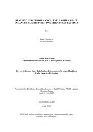
RJ-A3 Caged Float Valve<br />
The RJ-A3 is a two-piece valve unit to maximize vapour rate<br />
flexibility. It comprises of a moveable light weight valve disk<br />
which is enclosed in an open orifice cage structure with four<br />
legs that are attached firmly to the tray floor. Dependant upon<br />
the vapour rate, the valve disk moves up or down within the<br />
cage structure and the maximum opening is controlled by the<br />
height of the cage legs. The light weight disk contains antistick<br />
spacer tabs such that when the valve is closed at low<br />
vapour rates, the annular space created by the tabs allows<br />
intense mixing of the horizontal vapour flow with cross flowing<br />
liquid. This prevents the valve disk from sticking to the tray<br />
floor floor. If desirable, desirable flush seat RJ-A3 RJ A3 caged valves can be<br />
offered.<br />
closed<br />
open cage<br />
plate<br />
direction of flow<br />
direction of flow<br />
13
RJ-A3 Caged Float Valve<br />
in die Eckbegrenzungen<br />
(Größe 12,6 x,8 mm)<br />
kommt ein Foto<br />
<strong>Tray</strong> with Caged Valves (e.g. RJ-A3)<br />
14
RJ-A6 Caged Float Valve<br />
This valve type is the same as the RJ-A3 caged float valve<br />
except that the tray deck consists of a venturi-shaped orifice<br />
rather than a sharp-edge orifice. The venturi opening offers<br />
lower vapour rate flexibility due to the lower pressure drop.<br />
closed<br />
open<br />
cage<br />
plate<br />
direction of flow<br />
direction of flow<br />
15
Bubble Cap <strong>Tray</strong>s<br />
Bubble cap trays were the work horse tower internal in the first<br />
part of the twentieth century until the late 1950’s when it was<br />
superseded by sieve and valve trays. It consists of a flat<br />
perforated deck in which the holes are enclosed with vapour or<br />
gas chimney risers and caps in the form of inverted cups<br />
mounted on top of the risers. The caps can either be<br />
equipped with slots or holes, through which vapour escapes,<br />
or non-slotted where vapour is directed into the space<br />
between the bottom of the cap and tray floor (skirt clearance).<br />
Vapour is forced into the surrounding cross-flowing liquid such<br />
that aerated liquid is trapped on the tray floor to a depth at<br />
least equal to the weir height or riser height height. This gives the<br />
bubble cap tray the advantage to operate at extremely low<br />
liquid and vapour rates.<br />
in die Eckbegrenzungen<br />
(Größe 12,6 x,8 mm)<br />
kommt ein Foto<br />
16
Bubble Cap <strong>Tray</strong>s<br />
The main disadvantage, besides cost, is that a large fraction of<br />
the vapour phase pressure drop is wasted as it occurs in the<br />
reversal area between the chimney riser and cap.<br />
Consequently it does not contribute to the mass transfer<br />
process.<br />
Bubble cap p trays, y ggenerally, y have the ability y to handle wide<br />
ranges of liquid and vapour flow rates satisfactory due to their<br />
leak proof properties. This advantage is exploited in special<br />
applications such as gas scrubbers where a large amount of<br />
vapour must be in direct contact with the low liquid flow.<br />
Standard cap sizes of 75, 100 and 150 mm are available.<br />
Custom designs are also available.<br />
17
Specialty <strong>Tray</strong>s<br />
Dualflow <strong>Tray</strong>s<br />
Dualflow trays are essentially sieve trays without downcomers such<br />
that the entire tray active area is perforated with holes. Hole sizes<br />
range between 12.5 to 25 mm in diameter. <strong>Tray</strong> action occurs<br />
through the continuous countercurrent passage of vapour and<br />
liquid through the tray holes. As the liquid and vapour load are<br />
increased, the tray liquid head increases up to a point where a<br />
pulsating liquid seal is established at sufficiently high loads. At<br />
these conditions, liquid momentarily leaks through holes in areas of<br />
wave crests, while vapour surges through holes in the area<br />
between crests. As a result dualflow f trays only have a very<br />
narrow efficient operating range. High open hole area dualflow<br />
trays have a higher capacity and lower pressure drop compared to<br />
conventional distillation trays at the same tray spacing and are best<br />
suited for processing fluids that form polymers or have a high solids<br />
content. t t Th The majority j it off commercial i l applications li ti are common iin<br />
small to moderate sized columns. They are seldom used in larger<br />
diameter columns because of difficulties in achieving the desired<br />
tray tolerances for levelness. <strong>Tray</strong>s that suffer from out-ofevelness,<br />
are prone to segregation of the vapour-liquid flows which<br />
results lt iin llarge scale l li liquid id andd vapour maldsitribution.<br />
ld it ib ti<br />
.<br />
18
Specialty <strong>Tray</strong>s<br />
Nye <strong>Tray</strong>s<br />
Nye trays were developed to provide a cost effective way to<br />
significantly increase the capacity of existing distillation towers.<br />
Compared to a conventional valve or sieve tray a significant<br />
higher capacity can be achieved. The general design of Nye trays<br />
can be compared to conventional valve or sieve trays containing<br />
the same three general regions: the active area (contact zone), the<br />
disengagement zone of vapour and liquid above the active area<br />
and the downcomer.<br />
Compared to a conventional tray the inlet panel is modified. The<br />
Nye insert consists of an elevated inlet panel with perforations in<br />
the vertical face to the tray above.<br />
19
Specialty <strong>Tray</strong>s<br />
Nye <strong>Tray</strong>s<br />
With this design, on the one hand the active area is increased by<br />
the perforated vertical face which lowers the pressure drop. In<br />
addition to that the disengagement zone above the tray deck is<br />
increased. With those advantages, Nye trays consistently provide a<br />
higher capacity than conventional valve or sieve trays. A further<br />
advantage of the Nye tray is the fact that for a revamp only minimal<br />
tower modifications have to be made and the existing supports can<br />
be reused. For new column, considering the same capacity than<br />
conventional trays, the column diameter can be reduced and so the<br />
initial investment will be reduced.<br />
.<br />
20
Specialty <strong>Tray</strong>s<br />
Side-to-Side Baffle <strong>Tray</strong>s and Disc & Donut <strong>Tray</strong>s<br />
These two tray types are located inside a column in such a manor<br />
that the liquid and vapour are brought in to direct contact by forcing<br />
vapour through falling liquid. Liquid descends from one tray to the<br />
next either as a curtain of liquid raining down or as liquid rivulets<br />
passing through holes in the tray deck. <strong>Tray</strong> panels are flat or<br />
slightly inclined decks that occupy 40-60 % of the column crosssectional<br />
area. Designs containing panels with holes are usually<br />
40% open so that there is sufficient overlap between plates stacked<br />
one above the other. At a given tray spacing, both tray types offer a<br />
higher capacity and lower pressure drop compared with<br />
conventional sieve and valve trays, and in some cases dualflow<br />
trays. The trade-off is a considerably lower contacting efficiency.<br />
With both baffle trays and disc & donut trays having an extremely<br />
high open area, they are most suitable for dirty service and<br />
hheavy ffouling li applications. li ti EExamples l are hheavy oil il refining fi i andd<br />
petrochemical heat transfer services having a petroleum coke /<br />
high solids content. The Raschig Jaeger Group can supply these<br />
trays on request.<br />
21
Comparison of Common<br />
Conventional <strong>Tray</strong> Types<br />
TRAY TYPE BUBBLE CAP DUALFLOW SIEVE VALVE<br />
(Moving / Non-Moving)<br />
Capacity Moderate Very High High High to very high<br />
Pressure<br />
Drop<br />
Efficiency Moderate<br />
(0.6 – 0.8)*<br />
High Low to<br />
Moderate<br />
Turndown Very high<br />
Can handle very<br />
low liquid rates<br />
Lower<br />
compared to<br />
others<br />
(0.5 – 0.7)*<br />
Low. Not<br />
suitable for<br />
varying loads<br />
Low to<br />
Moderate<br />
High<br />
(0.7 – 0.9)*<br />
Approx. 2:1.<br />
Unsuitable for<br />
varying loads<br />
operation<br />
Moderate. Older<br />
designs were somewhat<br />
higher.Recent g designs g<br />
same as sieve trays.<br />
High<br />
(0.7 – 0.9)*<br />
Approx. 3-5:1<br />
Higher turndown<br />
designs can be<br />
provided on request.<br />
Maintenance Relatively high Low Low Low to moderate<br />
Fouling<br />
Tendency<br />
Main<br />
Application<br />
High. Tends to Extremely low.<br />
accummulate Best choice for<br />
solid particles p Severe foulingg<br />
Very low flow<br />
conditions<br />
Where leakage<br />
needs to be<br />
minimized<br />
Cost High - approx.<br />
2-3 times that<br />
for sieve trays<br />
* Within optimum operating range.<br />
Capacity<br />
Revamps<br />
Where<br />
efficiency and<br />
Turndown not<br />
Critical High<br />
fouling and<br />
corrosive i<br />
services.<br />
Low Low to moderate<br />
Most columns<br />
where<br />
Turndown<br />
not important<br />
Most Columns<br />
Services where<br />
turndown important<br />
Low Low Marginally higher than<br />
sieve trays<br />
22
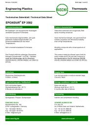
Below is a summary of the tray geometry<br />
and layout for the different conventional<br />
tray types at different operating<br />
pressures.<br />
Vacuum<br />
Distillation<br />
Normal<br />
Pressure<br />
Distillation<br />
<strong>Tray</strong> Spacing, m 0.5-0.8 0.4-0.6 0.3-0.4<br />
Weir length, m (0.5-0.6) D S * (0.6-0.75) D S * (0.85) D S *<br />
Downcomer Clearance Clearance, m 07h 0.7 hW* Bubble cap tray<br />
08h 0.8 hW* 09h 0.9 hW* <strong>Tray</strong> diameter, m 0.3 - 8 0.3 - 8 0.3 - 8<br />
Bubble cap diameter d Gl , m 0.08-0.16 0.08-0.16 0.08-0.16<br />
Distance between bubble caps, m 1.25 dGl (1.25-1.4) dGl 1.5 dGl Outlet weir height hW in m 0.02-0.03 0.03-0.07 0.04-0.1<br />
Sieve tray<br />
<strong>Tray</strong> diameter, m 0.3 - 8 0.3 - 8 0.3 - 8<br />
Hole diameter d h , m 0.003-0.015 0.003-0.015 0.003-0.015<br />
Hole pitch, m (2.5-3) dh (3-4) dh (3.5-4.5) dh Open hole area, % 10-20 6-15 6-10<br />
Outlet weir height h W , m 0.01-0.02 0.02-0.05 0.04-0.08<br />
Valve tray<br />
<strong>Tray</strong> diameter, m 0.3 - 10 0.3 - 10 0.3 - 10<br />
Valve diameter d V V,<br />
m 0.038-0.05 0.038-0.05 0.038-0.05<br />
Valve lift, m 0.008-0.02 0.008-0.02 0.008-0.02<br />
Valve open Slot Area, % 22-32 16-24 12-16<br />
Distance between valves, m 1.5 dV (1.7-2.2) dV (2-3) dV Outlet weir height hW in m 0.02-0.04 0.03-0.05 0.04-0.07<br />
*DS DS = column diameter in m<br />
hW = outlet weir height in m<br />
Pressure –<br />
Distillation and<br />
Absorption<br />
23
BBeyond d a certain t i li liquid id rate t th the ttray fl flow pathneeds th d tto bbe spilt ilt iin tto<br />
two or more paths. The following table shows recommended<br />
minimum diameters for trays with multiple flow paths<br />
Number of flow paths Recommended minimum<br />
diameter in m<br />
2 1.7<br />
3 2.4<br />
4 3.2<br />
Special <strong>Tray</strong> Design Accessories<br />
The Raschig Jaeger Group offers a range of tray accessories to<br />
produce an optimal solution to almost any fractionation tray<br />
problem. Mechanical and / or process considerations will indicate<br />
when special features are needed.<br />
Downcomer Designs<br />
Downcomer designs offered by the Raschig Jaeger Group include<br />
multi-chordal, circular, envelope, and pipe styles. These<br />
downcomer types can be supplied in additional to the straight<br />
segmental downcomers.<br />
Swept-back Weirs<br />
Swept back weirs are essentially used for high liquid loads. They<br />
are an extension of the chordal weir length, such that it lowers the<br />
tray liquid flux (volumetric liquid flow per unit length of outlet weir) weir),<br />
without changing the downcomer area. For 3- and 4-pass trays,<br />
swept back weirs are used to extend the length of side<br />
downcomers. This enables the balancing of liquid weir loads<br />
between the side and off-center or side and center downcomers.<br />
Swept back weirs lower tray pressure drop and downcomer<br />
backup.<br />
24
Circular or Downpipe Downcomers<br />
Pipe downcomers are only used for extremely low liquid load<br />
applications where standard segmental downcomers are<br />
unsuitable. Segmental weirs are used with pipe downcomers<br />
to ensure a good liquid distribution on the tray which helps lower<br />
the tray pressure drop.<br />
Envelope Downcomers<br />
Envelope downcomers are used in only low liquid rate applications<br />
in which a minimum downcomer width or minimal liquid leakage<br />
criteria has to be met.<br />
Sloped p Downcomers<br />
Sloped downcomers offer the best use of column area for<br />
downflow. They provide adequate volume for vapour-liquid<br />
disengagement at the downcomer top without sacrificing tray active<br />
area on the deck below. Sloped downcomers are very useful when<br />
vapour disengagement from the liquid flow in the downcomer is<br />
difficult (e.g., high pressure applications, foaming systems) and<br />
when downcomers occupy a significant part of the tray area (e (e.g., g<br />
high liquid loads). The extent of downcomer sloping is such that<br />
the bottom downcomer area is no less than 50 % of the top<br />
downcomer area.<br />
Anti-jump Baffles<br />
When operating at high rates, solid vertical panels known as antijump<br />
baffles are installed at the center and off-center downcomers<br />
of multi-pass trays. Operating problems may arise with aerated<br />
liquid jumping across the center and/or off-center downcomer from<br />
one tray panel to an opposing tray panel resulting in excessive<br />
liquid buildup near the tray outlet. Anti-jump baffles deflect liquid<br />
directly in to the downcomer. They are used when the width of the<br />
center or off-center off center downcomer is narrow and the tray loading is<br />
high.<br />
25
03/2009<br />
Picket-Fence Weirs<br />
Picket fence weirs are typically used at very low liquid rates<br />
(< 8.94 m3/h/m) in which there is a need to ‘artificially’ increase the<br />
tray liquid head to achieve performance. By using a continuous<br />
metal plate with rectangular notches or a number of equally spaced<br />
attached splash p p plates, , the effective weir length g is reduced. This in<br />
turn increases the liquid flux over the outlet weir and thus increase<br />
the liquid head on the tray active area.<br />
Splash Baffles<br />
For extremely low liquid rate services a splash baffle can also be<br />
provided and is similar to the picket fence weir. This is a metal<br />
plate set up parallel to the outlet weir set at a short distance above<br />
the tray floor. The splash baffle serves as an underflow weir for the<br />
liquid, is positioned in the near vicinity of the outlet weir and serves<br />
the purpose of increasing the liquid retention time on the tray.<br />
Recessed Seal Pans<br />
Recessed Inlet seal pans distribute liquid on to the tray in an<br />
upward vertical motion rather than horizontally through the inlet<br />
downcomer clearance. The result is better aeration at the tray<br />
active area entrance which can increase the tray capacity. They<br />
are used to provide a downcomer seal in cases where there<br />
sealing problems and when the clearance under the downcomer is<br />
limited according to standard methods.<br />
Recessed inlet pans are used together with sloped downcomers<br />
The bottom of the downcomer extends about 25 – 38 mm below<br />
the tray floor to ensure a good liquid seal. Slope downcomers with<br />
recessed inlet pans are used primarily in high liquid loaded<br />
services that suffer from downcomer flooding.<br />
<strong>RASCHIG</strong> GMBH<br />
Prof. Dr.-Ing. Michael Schultes<br />
Mundenheimerstr Mundenheimerstr. 100<br />
D-67061 Ludwigshafen<br />
phone.: +49 (0)621 56 18 - 648<br />
fax: +49 (0)621 56 18 - 627<br />
e-maill: MSchultes@raschig.de<br />
www.raschig.com<br />
Jaeger Products Inc.<br />
Mr. John P. Halbirt<br />
1611 Peachleaf<br />
USA-Houston, Texas 77039<br />
phone: +1 281 449 9500<br />
fax: +1 281 449 9400<br />
email: jhalbirt@jaeger.com<br />
www.jaeger.com<br />
26 23