

assembly instructions - Alden Rowing Shells
assembly instructions - Alden Rowing Shells
assembly instructions - Alden Rowing Shells

Create successful ePaper yourself
Turn your PDF publications into a flip-book with our unique Google optimized e-Paper software.
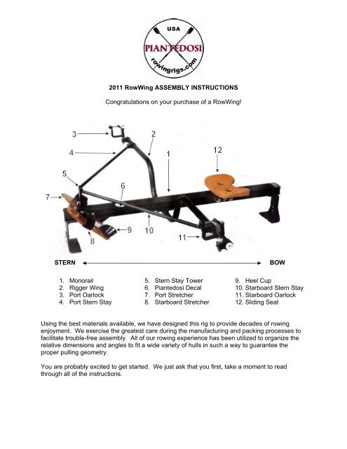
1. Monorail<br />
2. Rigger Wing<br />
3. Port Oarlock<br />
4. Port Stern Stay<br />
2011 RowWing ASSEMBLY INSTRUCTIONS<br />
Congratulations on your purchase of a RowWing!<br />
STERN BOW<br />
5. Stern Stay Tower<br />
6. Piantedosi Decal<br />
7. Port Stretcher<br />
8. Starboard Stretcher<br />
9. Heel Cup<br />
10. Starboard Stern Stay<br />
11. Starboard Oarlock<br />
12. Sliding Seat<br />
Using the best materials available, we have designed this rig to provide decades of rowing<br />
enjoyment. We exercise the greatest care during the manufacturing and packing processes to<br />
facilitate trouble-free <strong>assembly</strong>. All of our rowing experience has been utilized to organize the<br />
relative dimensions and angles to fit a wide variety of hulls in such a way to guarantee the<br />
proper pulling geometry.<br />
You are probably excited to get started. We just ask that you first, take a moment to read<br />
through all of the <strong>instructions</strong>.
Required Tools<br />
• 2 - ¾” wrenches (box or open) or 1 wrench and 1 ¾” socket with ratchet<br />
• 1 - 7/16” box end wrench or socket with ratchet<br />
• 1 - ½” wrench or socket with ratchet<br />
• 1 - 11/32” box end wrench or socket with ratchet<br />
• 1 - #2 Phillips head screwdriver<br />
• 1 - #1 Phillips head screwdriver<br />
• 1 - 7/32” hex key (can be found within the foot stretcher <strong>assembly</strong> box)<br />
• 1 - 3/16” hex key (can be found within the foot stretcher <strong>assembly</strong> box)<br />
Recommended Supplies<br />
‘Never-Seez’ anti-galling paste and either non-permanent thread-locker (usually blue) or<br />
plumber’s Teflon tape<br />
Instructions<br />
Our RowWing can be fitted into a variety of hulls, using one of our standard mounting kits or a<br />
custom kit specified by your boat manufacturer. These <strong>instructions</strong> are for assembling our<br />
‘RowWing Sliding Seat Base Unit’.<br />
STEP 1: Unpack and Locate the Following:
• 1 - 52” monorail<br />
• 1 - 65” rigger<br />
• 2 - 31” stern stays<br />
• 1 - Carton 11” x 8” x 4” (contains components and fasteners)<br />
• 1 - Carton 14” x 5” x 4” (contains a foot stretcher kit)<br />
• 1 - Plastic seat top (or wood, if you ordered a mahogany upgrade)<br />
STEP 2: Assemble the Foot Stretcher Kit<br />
Parts List<br />
• 2 - wooden or plastic foot pads<br />
• 2 - aluminum stretcher brackets (left and right)<br />
• 2 - aluminum stretcher t-blocks<br />
• 2 - Velcro foot straps<br />
• 2 - plastic heelcups<br />
• 1 - plastic bag containing;<br />
• 1 - plastic hex-wrench holder<br />
• 1, 2, or 3 - stainless hex-wrenches<br />
• 4 - ¼-20 x 1.25” Phillips flat head machine screws<br />
• 4 - ¼-20 elastic stop nuts<br />
• 4 - ¼-20 x .75” socket head cap screws<br />
• 4 - ¼” flat washers<br />
• 6 - #6 x ½” Phillips flat head wood screws (brass)<br />
REQUIRED TOOLS<br />
• 1 - #2 Phillips head screwdriver<br />
• 1 - 7/16” nut driver, socket (and ratchet), or box-end wrench (offset)<br />
STEP 2A<br />
Make sure you have all of the parts noted on the PARTS LIST.<br />
FIGURE #1
STEP 2B<br />
Attach one t-block to each of the footstretcher brackets, using the socket head cap screws and<br />
flat washers. Refer to Figure #1. Place the washers on the screws and then insert the screws<br />
through the holes of the triangular section of the stretcher bracket. Insert the screws from the<br />
inside or concave section of the bracket heading out. Thread the screws into the captive nuts of<br />
the t-blocks. The smaller face of the t-block should be against the bracket. On the t-block, the<br />
edge parallel and closest to the two captive nuts should line up with the longest leg of the<br />
triangular section of the stretcher bracket. For now, leave these screws loosely threaded.<br />
STEP 2C<br />
Attach one heelcup to each footpad using the brass wood screws. Refer to Figure #2. Locate<br />
the heelcups on the side of the footpad on which the four large holes are countersunk. Screw<br />
into the predrilled holes until snug. Be careful not to over-tighten and ‘strip’ these holes.<br />
STEP 2D<br />
Place the Phillips flat head machine screws in the holes of the footpads (two per footpad). You<br />
may have to screw through a varnish build-up. Select either the first and third holes or the<br />
second and fourth holes. Refer to Figure #2. By selecting the first and third holes, you allow<br />
your heels to be lower in the boat which is more comfortable for larger or less flexible rowers.<br />
With your feet lower, it is possible to compress at the ‘catch’ position (your shins should be<br />
perpendicular) without your heels coming out of the heelcups. Another point regarding lower<br />
heels: it makes it easier to sit properly, i.e., on your thighs/butt rather than on your butt/back.<br />
When rowing, you should keep your back arched and pivot at the hips to swing and reach.<br />
When you are sitting on your back more than your thighs, your spine curves and strains, which<br />
could lead to undue injury. In this position, your chest is also sunken, making it harder to<br />
breathe. The easiest way to keep your back arched is to keep your chin up. Smaller rowers<br />
may wish to use the second and fourth holes, so the foot strap will fit better. Another option is to<br />
row wearing sneakers, which for smaller feet will fit within the heelcups and under the straps.<br />
FIGURE #2
STEP 2E<br />
Position the Velcro foot straps. Refer to Figure #3. The straps are held in place, when the<br />
footpads are fastened to the brackets. The fuzzy (softer) side of the Velcro bears against your<br />
foot and should be mounted against the footpad. With the top face (countersunk side) of the<br />
footpad facing up, position one end of the strap at the instep edge with the rest of the length<br />
laying across the face of the pad (remember – fuzzy side against the pad). Wind the strap<br />
around the back of the footpad (between the two screws in place from Step 4) and continue<br />
around the instep, so the Velcro fastens to itself. The tail end should be heading away from the<br />
instep, but not wound around the back for another revolution.<br />
STEP 2F<br />
Mount the footpads onto the footstretcher brackets. The footpads are fitted to the inside or<br />
concave section of the brackets. The triangular section of the bracket with the attached t-block<br />
should be on the instep side of the footpad. The longest leg of the triangular section of the<br />
bracket should be facing up toward the toes. The screws positioned in Step 4 should pass<br />
through the two holes punched in the long rectangular tab of the bracket.<br />
STEP 2G<br />
FIGURE #3<br />
Mount the toolholder. If you are right-handed, place the toolholder under the right footpad. If<br />
you are left-handed, place the toolholder under the left footpad. Mount the toolholder so the<br />
largest hole of the three in a row is at the top, closest to the toes. The flat side fits against the<br />
bracket so the nuts will fit in the recesses. Start the nuts by hand and tighten with the Phillips<br />
screwdriver and one of the wrenches listed under ‘Required Tool’. You will need one of these to
fit into the recesses. Alternatively, tighten each one until snug. The bracket will compress the<br />
Velcro but you should not get either edge of the aluminum stretcher bracket in contact with the<br />
foot pad. Install your hex keys with the longer legs inserted into the holes. NOTE: Units<br />
purchased with the gunwale clamp system are equipped with three hex wrenches. Units<br />
purchased with deck plate or stanchion kits are equipped with only the two larger keys. Units<br />
without our rigger system (monorail only – specifically Laser & Saroca) are equipped with only<br />
the middle size hex wrench.<br />
STEP 2H<br />
Attach the nuts to the remaining footpad (without toolholder) and tighten as in Step 7.<br />
STEP 2I<br />
Attach footstretchers to monorail. Slide the footstretchers onto either side of the monorail<br />
starting from the stern end (opposite the bumper). The t-blocks fit into the channel created by<br />
the longitudinal tracks (or ‘ears’) on each side of the rail. The t-blocks must be loose enough to<br />
slide into position. Tighten the socket head screws equally using the middle size hex key.<br />
STEP 2J<br />
Adjusting the footstretchers. Assuming that your legs are the same length, you would want the<br />
footstretchers to be exactly opposite one another. While on the water, set the position of the<br />
footstretchers along the monorail, so that at the release position (legs fully extended, scull<br />
handles at release position, upper body pivoted into bow 10º from vertical (refer to Figure #4)),<br />
the oar handles are comfortably at your ribs, not inches in front of you or way out to the side and<br />
not so close that excessive layback must be used to extricate the oars from the water.<br />
Your elbows should be hanging down in a relaxed position, so that<br />
they will pass closely by your torso as you finish the stroke.<br />
Put this aside, for the moment.<br />
Position at the finish of the drive.
STEP 3: Assemble the Seat<br />
From within the 14” x 8” x 4” carton, find the flat seat plate and seat carriage (with the wheels<br />
attached). Locate the plastic bag containing:<br />
• 4 - 8-32 x ½” Phillips flat head machine screws<br />
• 4 - 8-32 elastic stop nuts<br />
• 2 - 5/16-18 x ¾” socket button head cap screws<br />
• 2 - 5/16-18 elastic stop nuts<br />
• 4 - 5/16” washers<br />
BOW<br />
Attach the seat plate to the carriage, using the 8-32 screws and nuts. You will need a Phillips<br />
head screw driver and an 11/32” wrench. The seat plate fits flush at one end of the seat<br />
carriage and extends 1” beyond the other end. The plastic seat top bolts to the seat plate, using<br />
the 5/16” machine screws, washers and nuts. It must be positioned, so that the stern edge is<br />
supported by the exposed seat plate. (See Photo #1).<br />
PHOTO #1<br />
BOW<br />
STERN<br />
STERN
Put the seat aside, for the moment.<br />
Note: If you chose the ‘mahogany upgrade’, your seat plate will attach to the seat carriage in a<br />
similar fashion. The wooden seat top is attached to this plate using four #10 x 5/8 stainless<br />
steel wood screws.<br />
STEP 4: Attach the Rigger<br />
Locate the bag containing:<br />
• 2 - 3/8-16 x 1 socket button head cap screws<br />
• 2 - 3/8” washers<br />
• 4 - ¼-20 x ¾” socket head cap screws<br />
• 4 - ¼” washers<br />
• 2 - rubber washers<br />
The bottom of the monorail has six embedded captive nuts. With the rail upside down and<br />
spanning two saw horses or chairbacks, bolt the rigger to the larger pair of inserts near the<br />
middle of the rail. Use the two 3/8-16 x 1 button head screws and washers. You will need to<br />
use the 7/32” hex key (provided). Store this key in the tool holder, under the footpad.<br />
STEP 5: Stern Stay Assembly<br />
Bolt the stern stay tower to the stern end of the monorail (top side) with two ¼” cap screws and<br />
washers (See Figure 1 & Photo #1).<br />
FIGURE #1 FIGURE #1
PHOTO #1<br />
Rigs using gunwale clamp kits should now install the tube clamps. (See Photo #2).<br />
PHOTO #2<br />
Slide the stern stay knuckles over the ends of the rigger arms. The tabs extending from the<br />
knuckle should be on the stern side of the rigger. The tab with the stainless insert should be on<br />
the bottom, so that the screw inserts from the top. Remove the ¼” cap screw from each<br />
knuckle. Affix one self-adhesive rubber washer to the flat end of each stern stay. Position the<br />
flat end of the stern stay between the two tabs of the knuckle (See Figure #2). The curved ends<br />
of the stern stays should be oriented in such a way that they fit against the face of the stern stay<br />
tower (See Figure #3). Reinsert the ¼” cap screws into the knuckles (through the rubber<br />
washers and stern stay). Leave this loose for now.<br />
FIGURE #2
FIGURE #3<br />
Adjust the position of each knuckle along the length of the outrigger, until the curved end of the<br />
stern stay is flat against the tower and the holes are aligned. Bolt the stern stays to the tower,<br />
using the remaining ¼” cap screws and flat washers. Tighten securely.<br />
Slightly twist the stern stay knuckles on the rigger to remove any tension. Tighten securely.<br />
Your rig should look like Photo #3 below.<br />
PHOTO #3
STEP 6: Oarlock Assembly/Adjustment Instructions<br />
Familiarize yourself with the components and study Figure #4 and Figure #5 below.<br />
Before you assemble the oarlocks, you should understand how they function and how the<br />
adjustments will affect your comfort and efficiency. Sculling oarblades are designed to form a<br />
‘puddle’, as you apply power to the oar handle. The oar is a lever, the oarlock/pin is a fulcrum<br />
and the ‘puddle’ is an anchor point. You do not draw the blades through the water; you pry the<br />
boat past the anchor point. You want the oarblade to maintain its depth and resulting hold at<br />
the anchor point, without diving too deep or ‘washing out’ over the water’s surface. Traditional<br />
flat bladed, round shaft Dory oars used in fixed seat rowing are controlled by flexing and rotating<br />
your wrists. <strong>Rowing</strong> with a sliding seat, however, utilizes the considerable power of your legs.<br />
You will not be able to maintain the angle of the oar blade within your grip, when you apply your<br />
leg drive. The sculling oar is designed with a ‘D’ shaped cross section, where it passes through<br />
the oarlock. The flat section of the ‘D’ is in the same plane as the oar blade. The flat section of<br />
the oar bears up against the face of the oarlock (Figure #4), so that you do not have to hold the<br />
angle in your grip. The proper grip is represented in Figure #5.<br />
FIGURE 4 FIGURE 5<br />
1. Oarlock Pin 6. Retainer Bolt<br />
2. Pin Stop-Nut 7. Oarlock Face<br />
3. Oarlock Knuckle 8. Oarlock Gate<br />
4. Pin Jam-Nut 9. Gate Adjusting Nut<br />
5. Nylon Spacers 10. Gate Locking Knob<br />
The angle of the face of the oarlock, and therefore the blade of the oar, become critical factors<br />
in maintaining blade depth. This measurement is referred to as ‘lateral’ or ‘fore and aft’ pitch. It<br />
is measured in the number of degrees that the blade is tipped over toward the stern from the<br />
vertical position. You can set the pitch of the oarlocks, using the appropriate ‘Pitch Plugs’ from<br />
the set provided. Pitch is adjustable from 1 to 7 degrees. See Figure #6 to understand how to<br />
install these plugs.
FIGURE #6<br />
Instructions for Using the Bushings to<br />
Adjust Pitch<br />
Adjust oarlock pitch from 1 to 7 degrees by<br />
selecting two bushings with the desired<br />
pitch imprinted and inserting them in<br />
opposite directions as shown in the<br />
drawing. (If replacing existing oarlocks,<br />
keep in mind that most non-adjustable<br />
oarlocks have a built-in pitch of 4 degrees.)<br />
You should start by setting the pitch at 4 degrees. If the blade dives, you should reset the pitch<br />
to 5 or 6 degrees. If the blade ‘washes out’, you should reduce the pitch to 3 degrees.<br />
Install the 4 degree Pitch Plugs in the oarlocks now. (Knuckles and pins on the rigger)<br />
The following <strong>instructions</strong> concern parts which are already assembled in your kit.<br />
Slide a ½” washer over the threaded section of the pin, followed by an oarlock knuckle, and<br />
then, a second ½” washer. At this point, you should apply some Never-Seez to the oarlock<br />
threads. Stainless fasteners tend to gall or weld themselves together under load. As its name<br />
indicates, ‘Never-Seez’ should prevent this occurrence. Screw on the ½-13 elastic stop nut.<br />
Repeat for the other set. (Refer to the Oarlock Assembly ‘Exploded View’ Figure #4).<br />
Slip the knuckle and pin assemblies onto the ends of the outrigger. The tabs of the knuckle<br />
should be oriented toward the stern of the boat (See Figure #4). Using the two ¾” wrenches,<br />
tighten the stop nuts until snug, but loose enough to rotate the <strong>assembly</strong> (see Photo #4 below).<br />
PHOTO #4
You now have to set the pins plum (90 degrees vertical). The easiest way is to ‘eyeball’ the pin<br />
against a known vertical member. Once set, you should fully tighten the stop nut. Repeat for<br />
the other side, again ‘eyeballing’ the second pin, relative to the first. A more accurate method<br />
than ‘eyeballing’ is to use a bubble level. More accurate, still, and measureable, is the use of a<br />
‘pitch meter’.<br />
The next step involves setting the height of the oarlocks. The first thing you have to realize is<br />
that the oar handles will overlap, as they swing perpendicular to the boat. It is customary to<br />
have one hand (the left/starboard) pass over the other (See Figure #7). To accomplish this<br />
crossover, the starboard oarlock should be about ½” higher than the port oarlock. This height<br />
differential is affected by the placement of three more spacer washers under the starboard<br />
oarlock than under the port oarlock. The final determination of how many spacers to place<br />
under and over the lock (there are a total of six) cannot be determined, until you are on the<br />
water. You should sit in the boat at the ‘finish’ position (Refer to Figure #8). Your legs should<br />
be straight, your back leaning into the bow about ten degrees, your hands at your ribcage and<br />
the blades of your oars either flat on the water or perpendicular and just buried. At this point,<br />
the height of your hands should be just at your pecs. Adjust the height by adding or subtracting<br />
spacers above or below the lock. Keep in mind that the starboard oarlock should still have three<br />
more spacers underneath it than the port oarlock.<br />
FIGURE #7
FIGURE #8<br />
Position at Finish of the Drive<br />
Start by placing four spacers on the starboard pin, then, the oarlock – then, place the final two<br />
spacers on the pin. Put one spacer on the port pin -- then, the oarlock – then, five spacers.<br />
Place a 5/16” flat washer on the top of each pin. At this point, if available, you should coat the<br />
5/16” button head machine screw with a non-permanent thread locker, blue in color, or with<br />
plumber’s Teflon tape. This procedure will prevent the screw from vibrating or backing out<br />
during transportation or use.<br />
Screw into the top of each pin and tighten, using the 3/16” hex key.
Step 7: Install the Seat<br />
Remove the bumper from the bow end of the monorail, using the 3/16” hex key. With the rig<br />
right-side-up, slide the seat onto the rail. The large cutout is for your tailbone and should be<br />
oriented toward the bow end of the boat. Reattach the bumper, to keep the seat from rolling off.<br />
Step 8: Install the Foot Stretchers<br />
Slide the foot stretchers onto the stern end of the monorail. You may have to loosen the ‘T’<br />
blocks, in order to accomplish this. Once in position, lock in place using the 3/16” hex key.<br />
And you’re done!