FreeSpace E4 Series II Business Music System Owner's Guide - Bose
FreeSpace E4 Series II Business Music System Owner's Guide - Bose
FreeSpace E4 Series II Business Music System Owner's Guide - Bose

Create successful ePaper yourself
Turn your PDF publications into a flip-book with our unique Google optimized e-Paper software.
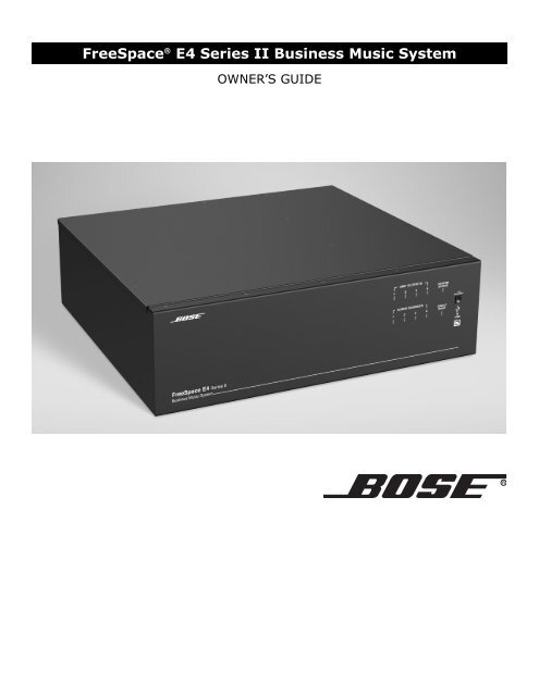
<strong>FreeSpace</strong> ® <strong>E4</strong> <strong>Series</strong> <strong>II</strong> <strong>Business</strong> <strong>Music</strong> <strong>System</strong><br />
OWNER’S GUIDE
1.0 <strong>E4</strong> Introduction . . . . . . . . . . . . . . . . . . . . . . . . . . . . 13<br />
1.1 The <strong>Bose</strong> ® <strong>FreeSpace</strong> ® <strong>E4</strong> <strong>Series</strong> <strong>II</strong> business<br />
music system . . . . . . . . . . . . . . . . . . . . . . . . 13<br />
1.2 <strong>E4</strong> system accessories . . . . . . . . . . . . . . . . . . . 13<br />
1.3 <strong>FreeSpace</strong> Installer software . . . . . . . . . . . . . 14<br />
2.0 Designing with the <strong>E4</strong> <strong>System</strong> . . . . . . . . . . . . . . . . . 15<br />
2.1 Introduction . . . . . . . . . . . . . . . . . . . . . . . . . . . . 15<br />
2.2 Basic design steps . . . . . . . . . . . . . . . . . . . . . . 15<br />
2.2.1 Step 1 – Determine source routing . . . . . . 15<br />
2.2.2 Step 2 – Determine Auto Volume<br />
requirements . . . . . . . . . . . . . . . . . . . . 15<br />
2.2.3 Step 3 – Determine volume control<br />
requirements . . . . . . . . . . . . . . . . . . . . 18<br />
2.2.4 Step 4 – Determine the speaker<br />
requirements . . . . . . . . . . . . . . . . . . . . 18<br />
2.2.5 Step 5 – Determine the <strong>E4</strong> requirements . 19<br />
2.3 Auto Volume layout examples . . . . . . . . . . . . . . 20<br />
3.0 <strong>E4</strong> Hardware Description . . . . . . . . . . . . . . . . . . . . 23<br />
3.1 Front panel . . . . . . . . . . . . . . . . . . . . . . . . . . . . 23<br />
3.1.1 Controls . . . . . . . . . . . . . . . . . . . . . . . . . . 23<br />
3.1.2 Indicators . . . . . . . . . . . . . . . . . . . . . . . . . 23<br />
3.2 Rear panel . . . . . . . . . . . . . . . . . . . . . . . . . . . . . 24<br />
3.2.1 <strong>System</strong> controls . . . . . . . . . . . . . . . . . . . . 24<br />
3.2.2 Audio source inputs . . . . . . . . . . . . . . . . . 24<br />
3.2.3 Amplifier outputs . . . . . . . . . . . . . . . . . . . 24<br />
3.2.4 AC power . . . . . . . . . . . . . . . . . . . . . . . . . 24<br />
4.0 Hardware Installation . . . . . . . . . . . . . . . . . . . . . . . . 25<br />
4.1 Introduction . . . . . . . . . . . . . . . . . . . . . . . . . . . . 25<br />
4.2 Included accessories . . . . . . . . . . . . . . . . . . . . 25<br />
4.3 Placement guidelines . . . . . . . . . . . . . . . . . . . . 25<br />
4.4 Shelf mounting the <strong>E4</strong> unit . . . . . . . . . . . . . . . . 25<br />
4.5 Rack mounting the <strong>E4</strong> unit . . . . . . . . . . . . . . . . 26<br />
4.6 Installing accessories . . . . . . . . . . . . . . . . . . . . 27<br />
4.6.1 Sensing microphones . . . . . . . . . . . . . . . . 27<br />
4.6.2 User interfaces . . . . . . . . . . . . . . . . . . . . . 27<br />
4.7 <strong>System</strong> wiring . . . . . . . . . . . . . . . . . . . . . . . . . . 29<br />
4.7.1 Auto volume microphone inputs . . . . . . . 29<br />
4.7.2 Serial data communications . . . . . . . . . . . 29<br />
4.7.3 User interface connections . . . . . . . . . . . . 29<br />
4.7.4 Remote standby switch . . . . . . . . . . . . . . 29<br />
4.7.5 LINE 1/LINE 2 source input . . . . . . . . . . . 30<br />
4.7.6 AUX MIC/LINE 3 source input . . . . . . . . . 30<br />
4.7.7 PAGE/MIC/LINE 4 source input . . . . . . . . 31<br />
4.7.8 DIRECT IN/CONTROL source input . . . . . 31<br />
4.7.9 Amplifier ZONE OUT outputs . . . . . . . . . . 32<br />
4.7.10 Output voltage setting (70/100V) . . . . . . 32<br />
4.7.11 ZONE 4 LINE OUT output . . . . . . . . . . . 33<br />
4.8 AC power connections . . . . . . . . . . . . . . . . . . . 33<br />
Contents<br />
11 of 80<br />
5.0 Using <strong>FreeSpace</strong> ® Installer Software . . . . . . . . . . 34<br />
5.1 Installing the software . . . . . . . . . . . . . . . . . . . . 34<br />
5.2 Connecting to the <strong>E4</strong> system . . . . . . . . . . . . . . 34<br />
5.2.1 No hardware detected . . . . . . . . . . . . . . . 36<br />
5.2.2 Incompatible microcontroller code . . . . . 36<br />
5.2.3 Sample design files . . . . . . . . . . . . . . . . . 36<br />
5.3 The Installer software user interface . . . . . . . 37<br />
5.4 Set Up Hardware mode . . . . . . . . . . . . . . . . . . 39<br />
5.5 Set Up Schedule mode . . . . . . . . . . . . . . . . . . . 40<br />
5.5.1 Setting the clock . . . . . . . . . . . . . . . . . . . 41<br />
5.5.2 Adding events . . . . . . . . . . . . . . . . . . . . . 41<br />
5.5.3 Viewing and changing event settings . . . 42<br />
5.5.4 Removing events from the list . . . . . . . . . 42<br />
5.6 Service Hardware mode . . . . . . . . . . . . . . . . . . 43<br />
6.0 <strong>E4</strong> <strong>System</strong> Setup . . . . . . . . . . . . . . . . . . . . . . . . . . 44<br />
6.1 Introduction . . . . . . . . . . . . . . . . . . . . . . . . . . . . 44<br />
6.2 Connecting your PC to an <strong>E4</strong> system . . . . . . . . 44<br />
6.3 <strong>System</strong> setup procedure . . . . . . . . . . . . . . . . . 45<br />
6.3.1 Output gain . . . . . . . . . . . . . . . . . . . . . . . 45<br />
6.3.2 Zone setup . . . . . . . . . . . . . . . . . . . . . . . . 46<br />
6.3.3 Input gain . . . . . . . . . . . . . . . . . . . . . . . . . 47<br />
6.3.4 Source assign . . . . . . . . . . . . . . . . . . . . . 49<br />
6.3.5 Source EQ . . . . . . . . . . . . . . . . . . . . . . . . 50<br />
6.3.6 Page set up . . . . . . . . . . . . . . . . . . . . . . . 50<br />
6.3.7 Zone EQ . . . . . . . . . . . . . . . . . . . . . . . . . . 52<br />
6.3.8 Dynamic EQ . . . . . . . . . . . . . . . . . . . . . . . 53<br />
6.3.9 Auto Volume . . . . . . . . . . . . . . . . . . . . . . . 53<br />
7.0 User Interface Operation . . . . . . . . . . . . . . . . . . . . . 59<br />
7.1 Enabling keypad operation . . . . . . . . . . . . . . . . 59<br />
7.2 Turning the system on . . . . . . . . . . . . . . . . . . . 59<br />
7.3 Standard user interface operation . . . . . . . . . . 59<br />
7.4 Auto Volume user interface operation . . . . . . . 60<br />
7.5 Multi-zone paging user interface operation . . . 61<br />
8.0 <strong>E4</strong> <strong>System</strong> Troubleshooting . . . . . . . . . . . . . . . . . . 62<br />
8.1 Introduction . . . . . . . . . . . . . . . . . . . . . . . . . . . . 62<br />
8.2 <strong>E4</strong> hardware indicators . . . . . . . . . . . . . . . . . . . 62<br />
8.2.1 Normal operation . . . . . . . . . . . . . . . . . . . 62<br />
8.2.2 <strong>System</strong> fault . . . . . . . . . . . . . . . . . . . . . . . 62<br />
8.2.3 Amplifier fault . . . . . . . . . . . . . . . . . . . . . . 63<br />
8.2.4 Input clipping . . . . . . . . . . . . . . . . . . . . . . 64<br />
8.2.5 Direct input is active . . . . . . . . . . . . . . . . 64<br />
8.2.6 No STANDBY and SYSTEM indicators . . 64<br />
8.3 <strong>FreeSpace</strong> ® <strong>E4</strong> system Error Log . . . . . . . . . . . 65<br />
8.3.1 Contents of the Error Log . . . . . . . . . . . . 65<br />
8.3.2 Hardware configuration . . . . . . . . . . . . . . 65<br />
8.3.3 Power-on self-test results . . . . . . . . . . . . 65<br />
8.3.4 Amplifier alarms . . . . . . . . . . . . . . . . . . . . 66<br />
8.3.5 Solving faults reported in the Error Log . . 67
8.4 Common problems . . . . . . . . . . . . . . . . . . . . . . 68<br />
8.4.1 Communications port error . . . . . . . . . . . 68<br />
8.4.2 No audio in zone . . . . . . . . . . . . . . . . . . . . 68<br />
8.4.3 User interface keypads do not<br />
operate correctly . . . . . . . . . . . . . . . . . 69<br />
8.4.4 Bad sound in a zone . . . . . . . . . . . . . . . . . 69<br />
8.4.5 Auto Volume does not calibrate . . . . . . . . 70<br />
8.5 Customer support . . . . . . . . . . . . . . . . . . . . . . . 70<br />
8.5.1 Technical assistance . . . . . . . . . . . . . . . . 70<br />
8.5.2 Reporting software bugs and issues . . . . 70<br />
9.0 Restoring <strong>E4</strong> Microcontroller Code . . . . . . . . . . . . . 72<br />
10.0 Technical Specifications . . . . . . . . . . . . . . . . . . . . 74<br />
10.1 Power amplifier . . . . . . . . . . . . . . . . . . . . . . . . 74<br />
10.2 Digital signal processing . . . . . . . . . . . . . . . . . 74<br />
10.3 Front panel indicators and control<br />
connections . . . . . . . . . . . . . . . . . . . . . . . . . . 74<br />
10.4 Rear panel inputs, outputs, and controls . . . . 74<br />
10.5 <strong>E4</strong> system serial data commands . . . . . . . . . . 74<br />
10.6 <strong>FreeSpace</strong> ® Installer Design File<br />
Compatibility . . . . . . . . . . . . . . . . . . . . . . . . . 76<br />
Contents<br />
12 of 80
1.1 The <strong>Bose</strong> ® <strong>FreeSpace</strong> ® <strong>E4</strong> <strong>Series</strong> <strong>II</strong><br />
business music system<br />
The <strong>Bose</strong> <strong>FreeSpace</strong> <strong>E4</strong> <strong>Series</strong> <strong>II</strong> system is an integrated fourchannel<br />
digital signal processor and 400-watt power amplifier for<br />
70/100V business music applications.<br />
The <strong>E4</strong> system has a total of four source inputs, including two<br />
Line In, one Mic/Line and one Mic/Page/Line, to provide the<br />
inputs needed for most business music installations. The system<br />
also has a direct input which can override the sources playing on<br />
all four output channels.<br />
The <strong>E4</strong> system has four amplifier output channels which can be<br />
configured for different zones. A <strong>Music</strong> on Hold output is also<br />
provided for simple integration into a phone system.<br />
In a single chassis, it provides all of the processing and control<br />
features required for one-to-four zone business music applications.<br />
These features include:<br />
• Auto Volume: When used with the optional <strong>FreeSpace</strong> system<br />
Auto Volume Sense Mic, <strong>E4</strong> system electronics dynamically<br />
control the program level in each zone so your customers can<br />
always hear it, regardless of the background noise.<br />
Scheduling: Allows you to program the <strong>E4</strong> system electronics<br />
for automated on/off control, source changes, and volume<br />
changes according to time of day or day of week.<br />
Multi-Zone Paging: Allows you to initiate a page from a single<br />
keypad to one or more of the zones being powered by the<br />
same <strong>E4</strong> system.<br />
Opti-voice ® Paging: Provides a smooth transition between<br />
music and page signals.<br />
Opti-source ® Input Leveling: Monitors the input level of up to<br />
four sources and continually makes adjustments to maintain a<br />
consistent volume level between different sources.<br />
Dynamic Equalization: Maintains tonal balance at all listening<br />
levels.<br />
Room Equalization: Provides easy adjustment of tonal balance<br />
in each zone.<br />
Signal Routing: Meets the demands of most four-zone systems,<br />
allowing for an input source to be routed to any of the<br />
four amplifier outputs.<br />
1.0 <strong>E4</strong> Introduction<br />
13 of 80<br />
Serial Data Interface: RS-232 serial port for easy interfacing<br />
to your PC<br />
Remote On/Off Input: Accepts a remote STANDBY switch<br />
The integrated 400-watt power amplifier features a patented<br />
power-sharing technology which dynamically allocates power to<br />
each output.<br />
For example, if you have a two-zone system that requires 5 watts<br />
in Zone 1 and 395 watts in Zone 2, the <strong>FreeSpace</strong> <strong>E4</strong> system<br />
electronics distributes the power based on those needs.<br />
The <strong>E4</strong> also includes an easy-to-replace memory module, which<br />
holds the system configuration settings and design file uploaded<br />
by the <strong>FreeSpace</strong> Installer software (see page 14).<br />
1.2 <strong>E4</strong> system accessories<br />
Optional <strong>Bose</strong> accessories for the <strong>E4</strong> system are available.<br />
<strong>FreeSpace</strong> <strong>E4</strong> <strong>System</strong> User Interface Kit (U.S.) (PC029856)<br />
A wall-mountable keypad that fits into a standard U.S. singlegang<br />
junction box. It provides buttons for volume up/down<br />
control, 1-3 source selection, and mute.<br />
<strong>FreeSpace</strong> <strong>E4</strong> <strong>System</strong> User Interface Kit (Euro) (PC029857)<br />
A wall-mountable keypad that fits into a standard Euro singlegang<br />
junction box. It provides buttons for volume up/down<br />
control, 1-3 source selection, and mute.<br />
<strong>FreeSpace</strong> ® <strong>E4</strong> <strong>System</strong> Auto Volume Interface Kit (U.S.)<br />
(PC030101)<br />
A wall-mountable keypad that fits into a standard U.S. singlegang<br />
junction box. It provides buttons for volume up/down<br />
control, 1-3 source selection, and Auto Volume on/off.<br />
<strong>FreeSpace</strong> <strong>E4</strong> <strong>System</strong> Auto Volume Interface Kit (Euro)<br />
(PC030102)<br />
A wall-mountable keypad that fits into a standard Euro singlegang<br />
junction box. It provides buttons for volume up/down<br />
control, 1-3 source selection, and Auto Volume on/off.<br />
<strong>FreeSpace</strong> <strong>E4</strong> <strong>System</strong> Auto Volume Mic Kit (U.S.)<br />
(PC029859)<br />
One sensing microphone that can be mounted as is or in a<br />
standard U.S. single-gang junction box.<br />
<strong>FreeSpace</strong> <strong>E4</strong> <strong>System</strong> Auto Volume Mic Kit (Euro)<br />
(PC029860)<br />
One sensing microphone that can be mounted as is or in a<br />
standard Euro single-gang junction box.<br />
<strong>FreeSpace</strong> <strong>E4</strong> <strong>System</strong> Accessory Kit (U.S.) (PC030105)<br />
Supplemental rear panel mating connectors and non-skid feet.<br />
<strong>FreeSpace</strong> <strong>E4</strong> <strong>System</strong> Rack Mount Kit (PC029858)<br />
One pair of rack ears.<br />
<strong>FreeSpace</strong> <strong>E4</strong> <strong>System</strong> Page Interface Kit (U.S.) (PC030103)<br />
A wall-mountable keypad that fits into a standard U.S. singlegang<br />
junction box. It provides buttons for 1-4 page zone selection,<br />
all page zones selection and initiate page.<br />
<strong>FreeSpace</strong> <strong>E4</strong> <strong>System</strong> Page Interface Kit (Euro) (PC030104)<br />
A wall-mountable keypad that fits into a standard Euro singlegang<br />
junction box. It provides buttons for 1-4 page zone selection,<br />
all page zones selection and initiate page.
1.3 <strong>FreeSpace</strong> Installer software<br />
<strong>Bose</strong> ® <strong>FreeSpace</strong> Installer software is included with every <strong>E4</strong> system.<br />
The Installer software allows you to configure hardware<br />
devices such as the <strong>E4</strong> system. The Installer software is designed<br />
for use on a PC that is connected to the <strong>E4</strong> system through a<br />
serial data interface.<br />
The Installer software requires a computer system with the following<br />
minimum requirements:<br />
400 MHz Pentium ® -based PC<br />
256 MB of RAM<br />
50 MB of available hard-drive space<br />
RS-232 serial port<br />
800 x 600 display<br />
4x CD-ROM drive<br />
Microsoft Windows ® 98, Windows ® 98SE, Windows ® NT,<br />
Windows ® 2000, Windows ® XP<br />
1.0 <strong>E4</strong> Introduction<br />
14 of 80
2.1 Introduction<br />
This section describes the basic steps for designing an <strong>E4</strong> system<br />
and includes an example. It is assumed that a complete<br />
loudspeaker design and layout has already been created.<br />
2.2 Basic design steps<br />
There are five basic steps in designing an <strong>E4</strong> system.<br />
2.2.1 Step 1 – Determine source routing<br />
Decide which sources will be played in each area. Create a<br />
“source map” such as the following one that shows which<br />
sources will be played in each major area of the facility.<br />
2.2.2 Step 2 – Determine Auto Volume<br />
requirements<br />
Identify which areas will use Auto Volume. Each Auto Volume<br />
zone must use one Auto Volume user interface and one <strong>Bose</strong> ®<br />
sensing microphone to control the volume. A 70/100V volume<br />
control cannot be used.<br />
When using Auto Volume, remember that you will be adjusting<br />
the volume of an overall area. Imagine that you have a dining area<br />
and a bar adjacent to one another. If the sensing microphone is<br />
placed above the bar, the music may become too loud in the dining<br />
area. Likewise, if you place the sensing microphone above<br />
2.0 Designing with the <strong>E4</strong> <strong>System</strong><br />
Source 1 Source 2 Source 3 Source 4<br />
Area 1 ● ●<br />
Area 2 ● ● ●<br />
Area 3 ● ●<br />
Area 4 ●<br />
Area 5 ●<br />
15 of 80<br />
the dining area, the music may never be heard in the bar.<br />
<strong>Guide</strong>lines for establishing Auto Volume zones<br />
Speaker<br />
height is…<br />
Background noise<br />
is uniform<br />
>25 ft (7.6 m) Not recommended<br />
12-25 ft<br />
(3.7-7.6 m)<br />
One Auto Volume<br />
zone for every<br />
3600 ft 2 (324 m 2 )<br />
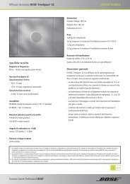
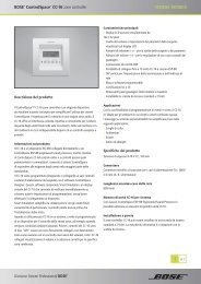
The following are examples of correct and incorrect sensing<br />
microphone placements:<br />
Installer’s Note: In applications where ceiling height is less<br />
than 12 feet (3.6 m), the microphone should be wall mounted.<br />
2.0 Designing with the <strong>E4</strong> <strong>System</strong><br />
Correct placement Incorrect placement<br />
Sensing<br />
microphone<br />
Ceiling Flush<br />
Wall Surface<br />
Correct placement Incorrect placement<br />
Sensing<br />
microphone<br />
16 of 80<br />
Sensing<br />
microphone<br />
Sensing<br />
microphone<br />
Mic
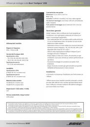
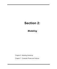
When mounting sensing microphones, always maintain a distance<br />
of 6 feet (1.8 m) minimum between the microphone and the<br />
speaker.<br />
Sensing<br />
microphone<br />
Ceiling Flush<br />
≥6 ft<br />
(1.8 m)<br />
2.0 Designing with the <strong>E4</strong> <strong>System</strong><br />
≥6 ft<br />
(1.8 m)<br />
6'<br />
≥6 ft<br />
(1.8 m)<br />
Ceiling Surface<br />
Mic<br />
17 of 80<br />
≥6 ft<br />
(1.8 m)<br />
6'<br />
Sensing<br />
microphone<br />
Wall Surface<br />
6'<br />
≥6 ft<br />
(1.8 m)<br />
Sensing<br />
microphone<br />
Mic<br />
≥6 ft<br />
(1.8 m)<br />
6'
2.2.3 Step 3 – Determine volume<br />
control requirements<br />
Decide which areas will have volume controls. Create a control<br />
map, such as the following, showing the types of controls that<br />
will be used, and the areas in which they will be installed.<br />
Auto<br />
Volume<br />
Interface<br />
1<br />
Area 1 ●<br />
Auto<br />
Volume<br />
Interface<br />
2<br />
Standard and Auto Volume interfaces are available for use with<br />
the <strong>E4</strong> hardware. Each offers control over source selection and<br />
volume. The Standard interface contains a Mute button, and the<br />
Auto Volume interface contains an Auto Volume on/off button. If<br />
you have identified an area that uses Auto Volume, you must use<br />
an Auto Volume interface to control this zone.<br />
It is also possible to use 70/100V volume controls between the<br />
amplifier output and the speaker. If you plan to use 70/100V controls,<br />
be aware that they cannot be used in zones where either<br />
Auto Volume or Dynamic EQ is used. Auto Volume and Dynamic<br />
EQ monitor the amplifier output and make adjustments accordingly.<br />
Using a 70/100V volume control would cause these functions<br />
to operate improperly.<br />
When determining the placement or physical location of the controls,<br />
first think about how the control is used. If the control is<br />
very rarely used or it requires a secure location, it should be<br />
placed with the equipment. If the control is for an area that<br />
requires frequent adjustments, then it is best to place the control<br />
in the area being controlled.<br />
2.0 Designing with the <strong>E4</strong> <strong>System</strong><br />
70/100V<br />
Volume<br />
Control<br />
1<br />
70/100V<br />
Volume<br />
Control<br />
2<br />
Area 2 ●<br />
Area 3 ●<br />
Area 4 ●<br />
Area 5 ●<br />
18 of 80<br />
2.2.4 Step 4 – Determine the speaker<br />
requirements<br />
Determine the speaker coverage required for the design. Consider<br />
the following points as you do this:<br />
Each Auto Volume function requires a separate zone. Each<br />
Auto Volume zone requires the dedicated use of one <strong>E4</strong> output<br />
channel.<br />
Each type of actively equalized speaker requires the dedicated<br />
use of one <strong>E4</strong> output channel. If you are designing a system<br />
that uses actively equalized speakers, such as the 102 ® F<br />
speaker, Model 32, Model 32SE, or Model 8, you must dedicate<br />
one <strong>E4</strong> output channel for each speaker type.<br />
Create a speaker map, such as the following, and match the<br />
speaker models to areas (Speaker Qty x Tap = Zone Power<br />
required):<br />
Model<br />
32SE <strong>FreeSpace</strong><br />
3-I<br />
Speaker<br />
Qty Tap<br />
Area<br />
Power<br />
Area 1 ● 2 50 100<br />
Area 2 ● 5 8 40<br />
Area 3 ● 1 50 50<br />
Area 4 ● 3 4 12<br />
Area 5 ● 6 8 48
2.2.5 Step 5 – Determine the <strong>E4</strong><br />
requirements<br />
Once you have identified the areas that use Auto Volume and<br />
unique loudspeakers, you can combine different areas based on<br />
the types of sources and controls they are using.<br />
2.0 Designing with the <strong>E4</strong> <strong>System</strong><br />
19 of 80<br />
Now we can take a look at how the maps we created can help us<br />
determine the quantity of <strong>E4</strong>s we will need.<br />
Sources Controls Loudspeakers<br />
1 2 3 4 AV1 AV2 VC1 VC2 M32SE FS3 Total W <strong>E4</strong> Ch.<br />
Area 1 ● ● ● ● 100 1<br />
Area 2 ● ● ● ● ● 40 2<br />
Area 3 ● ● ● ● 50 3<br />
Area 4 ● ● ● 12 4<br />
Area 5 ● ● ● 48 4<br />
Total <strong>System</strong> Power = 250W<br />
By combining the maps you can easily combine sources, speaker types, and control types. The information placed<br />
in this table suggests that Area 1 and Area 3 need to be grouped separately because they are Auto Volume zones<br />
requiring separate <strong>E4</strong> system outputs. Area 2 uses one standard volume control requiring one <strong>E4</strong> output channel.<br />
Areas 4 and 5 share a common volume control and can be combined on a third <strong>E4</strong> output channel. Since only four<br />
outputs are required and the total combined power requirement is less than 400W, only one <strong>E4</strong> unit would be<br />
needed for this system.
2.3 Auto Volume layout examples<br />
Large, open retail space with single music<br />
source<br />
<strong>FreeSpace</strong> ® Acoustimass module<br />
Model 16 (pendant mounted)<br />
Sensing microphone<br />
2.0 Designing with the <strong>E4</strong> <strong>System</strong><br />
20 of 80
Hair salon (Small space with specific noise)<br />
2.0 Designing with the <strong>E4</strong> <strong>System</strong><br />
<strong>FreeSpace</strong> ® 3 system<br />
Sensing microphone<br />
21 of 80
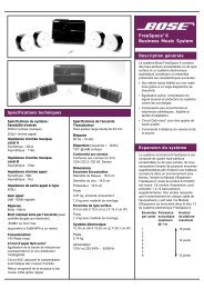
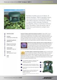
Hotel lobby<br />
2.0 Designing with the <strong>E4</strong> <strong>System</strong><br />
Model 16<br />
(flush mounted)<br />
Sensing microphone<br />
22 of 80<br />
22 ft<br />
(6.7 m)<br />
40 ft<br />
(12.2 m)
<strong>Bose</strong> ® Product Sales Conditions<br />
Limited Warranty Policy<br />
and<br />
Conditions of Sale<br />
<strong>Bose</strong> Corporation<br />
The Mountain<br />
Framingham, MA 01701<br />
What is covered:<br />
All parts defective in material and workmanship. This limited<br />
warranty for the <strong>Bose</strong> Freespace ® <strong>E4</strong> system (“system”) covers<br />
the functionality of the system for its normal, intended use as<br />
specified in the Owner’s <strong>Guide</strong> and does not cover a malfunction<br />
that has resulted from improper or unreasonable use or maintenance,<br />
accident, excess moisture, improper packing,<br />
lightning, power surges, or unauthorized tampering, alteration or<br />
modification while not under the control of <strong>Bose</strong>. <strong>Bose</strong> systems<br />
are not designed to be used in every environment, so please<br />
review your Owner’s <strong>Guide</strong>.<br />
WHERE PERMITTED, THE PROVISIONS OF THIS LIMITED<br />
WARRANTY ARE IN LIEU OF ANY OTHER WRITTEN<br />
WARRANTY, WHETHER EXPRESS OR IMPLIED, WRITTEN OR<br />
ORAL, INCLUDING ANY WARRANTY OF MERCHANTABILITY<br />
OR FITNESS FOR A PARTICULAR PURPOSE.<br />
For how long:<br />
In countries where the duration of the warranty is not determined<br />
by statute, the <strong>Bose</strong> Limited Warranty lasts five years from the<br />
purchase date. For countries where minimum warranty terms are<br />
determined by statute, the warranty term is the longer of the<br />
statutory period or the term listed above.<br />
What we will do:<br />
We will repair or replace any defective parts within a reasonable<br />
period of time and free of charge.<br />
How you can obtain warranty service:<br />
1. You can ship the system to either a <strong>Bose</strong> Service Agency or to<br />
<strong>Bose</strong> directly with a proof of purchase from an authorized dealer.<br />
Please:<br />
A. Properly and carefully pack the product for shipping. If you<br />
need a carton for shipping, contact <strong>Bose</strong> for a new carton.<br />
B. Label and ship the product to the appropriate <strong>Bose</strong><br />
location.<br />
C. Please contact <strong>Bose</strong> to get a return reference number.<br />
Place this number prominently on the outside of the carton.<br />
2. You can return the system with proof of purchase from an<br />
authorized dealer to a <strong>Bose</strong> Service Agency or directly to<br />
<strong>Bose</strong>. Proof of purchase is not required where it is excluded<br />
by statute.<br />
77 of 78<br />
Other Rights:<br />
EXCLUSIVE REMEDY:<br />
THIS LIMITED WARRANTY IS FULLY TRANSFERABLE<br />
PROVIDED THAT THE CURRENT OWNER FURNISHES THE<br />
ORIGINAL PROOF OF PURCHASE FROM AN AUTHORIZED<br />
BOSE DEALER. THE MAXIMUM LIABILITY OF BOSE SHALL<br />
NOT EXCEED THE ACTUAL PURCHASE PRICE PAID BY YOU<br />
FOR THE PRODUCT. IN NO EVENT SHALL BOSE BE LIABLE<br />
FOR SPECIAL, INCIDENTAL, CONSEQUENTIAL OR INDIRECT<br />
DAMAGES. SOME PLACES DO NOT ALLOW LIMITATIONS ON<br />
THE EXCLUSION OR LIMITATION OF RELIEF, SPECIAL,<br />
INCIDENTAL, CONSEQUENTIAL OR INDIRECT DAMAGES OF<br />
THE LIMITATION OF LIABILITY TO SPECIFIED AMOUNTS, SO<br />
THE ABOVE LIMITATIONS OR EXCLUSIONS MAY NOT APPLY<br />
TO YOU.<br />
OTHER CONDITIONS:<br />
FOR YOUR BENEFIT, WE RECOMMEND THAT YOU RECORD<br />
YOUR SERIAL NUMBERS(S), FOUND ON THE PRODUCT(S),<br />
AND OTHER PURCHASE INFORMATION, AND KEEP IT WITH<br />
YOUR PERSONAL RECORDS ALONG WITH PROOF OF<br />
PURCHASE. IF NECESSARY, THIS INFORMATION WILL<br />
ALLOW US TO BETTER SERVE YOUR NEEDS.<br />
THIS LIMITED WARRANTY GIVES YOU SPECIFIC RIGHTS<br />
SUBJECT TO SPECIFIED CONDITIONS. YOU MAY ALSO HAVE<br />
OTHER LEGAL RIGHTS WHICH APPLY TO THE PRODUCT<br />
YOU HAVE ACQUIRED. THESE LEGAL RIGHTS VARY FROM<br />
STATE TO STATE OR COUNTRY TO COUNTRY. SOME PLACES<br />
DO NOT ALLOW THE EXCLUSION, RESTRICTION OR MODIFI-<br />
CATION OF CERTAIN IMPLIED RIGHTS OR THEIR EFFECT. IN<br />
THOSE SITUATIONS THIS LIMITED WARRANTY WILL ONLY<br />
APPLY TO THE EXTENT THAT THE APPLICABLE LAW ALLOWS.<br />
OTHER LAWS PROVIDE YOU WITH A STATUTORY CLAIM<br />
AGAINST THE SELLER.<br />
The laws of your state or country may provide you with legal<br />
claims against the seller or manufacturer of this product. The<br />
Limited Warranty does not affect those rights.<br />
Remedies:<br />
The provisions of this limited warranty are in lieu of any other<br />
warranties or conditions, except those provided by law. This<br />
Limited Warranty does not affect any legal rights provided to you<br />
by law and does not preclude any legal remedy you may have<br />
under the law.<br />
This Limited Warranty is fully transferable provided that the<br />
current owner furnishes the original proof of purchase from an<br />
authorized <strong>Bose</strong> dealer.<br />
This Limited Warranty is void if the label bearing the serial<br />
number has been removed or defaced.
78<br />
©2004 <strong>Bose</strong> Corporation, The Mountain,<br />
Framingham, MA 01701-9168 USA<br />
279145 AM Rev.00 CCM-000922