FreeSpace E4 Series II Business Music System Owner's Guide - Bose
FreeSpace E4 Series II Business Music System Owner's Guide - Bose
FreeSpace E4 Series II Business Music System Owner's Guide - Bose

You also want an ePaper? Increase the reach of your titles
YUMPU automatically turns print PDFs into web optimized ePapers that Google loves.
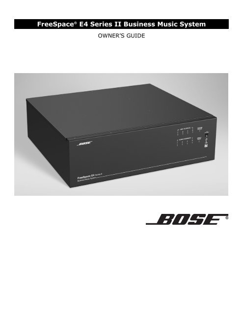
<strong>FreeSpace</strong> ® <strong>E4</strong> <strong>Series</strong> <strong>II</strong> <strong>Business</strong> <strong>Music</strong> <strong>System</strong><br />
OWNER’S GUIDE
1.0 <strong>E4</strong> Introduction . . . . . . . . . . . . . . . . . . . . . . . . . . . . 13<br />
1.1 The <strong>Bose</strong> ® <strong>FreeSpace</strong> ® <strong>E4</strong> <strong>Series</strong> <strong>II</strong> business<br />
music system . . . . . . . . . . . . . . . . . . . . . . . . 13<br />
1.2 <strong>E4</strong> system accessories . . . . . . . . . . . . . . . . . . . 13<br />
1.3 <strong>FreeSpace</strong> Installer software . . . . . . . . . . . . . 14<br />
2.0 Designing with the <strong>E4</strong> <strong>System</strong> . . . . . . . . . . . . . . . . . 15<br />
2.1 Introduction . . . . . . . . . . . . . . . . . . . . . . . . . . . . 15<br />
2.2 Basic design steps . . . . . . . . . . . . . . . . . . . . . . 15<br />
2.2.1 Step 1 – Determine source routing . . . . . . 15<br />
2.2.2 Step 2 – Determine Auto Volume<br />
requirements . . . . . . . . . . . . . . . . . . . . 15<br />
2.2.3 Step 3 – Determine volume control<br />
requirements . . . . . . . . . . . . . . . . . . . . 18<br />
2.2.4 Step 4 – Determine the speaker<br />
requirements . . . . . . . . . . . . . . . . . . . . 18<br />
2.2.5 Step 5 – Determine the <strong>E4</strong> requirements . 19<br />
2.3 Auto Volume layout examples . . . . . . . . . . . . . . 20<br />
3.0 <strong>E4</strong> Hardware Description . . . . . . . . . . . . . . . . . . . . 23<br />
3.1 Front panel . . . . . . . . . . . . . . . . . . . . . . . . . . . . 23<br />
3.1.1 Controls . . . . . . . . . . . . . . . . . . . . . . . . . . 23<br />
3.1.2 Indicators . . . . . . . . . . . . . . . . . . . . . . . . . 23<br />
3.2 Rear panel . . . . . . . . . . . . . . . . . . . . . . . . . . . . . 24<br />
3.2.1 <strong>System</strong> controls . . . . . . . . . . . . . . . . . . . . 24<br />
3.2.2 Audio source inputs . . . . . . . . . . . . . . . . . 24<br />
3.2.3 Amplifier outputs . . . . . . . . . . . . . . . . . . . 24<br />
3.2.4 AC power . . . . . . . . . . . . . . . . . . . . . . . . . 24<br />
4.0 Hardware Installation . . . . . . . . . . . . . . . . . . . . . . . . 25<br />
4.1 Introduction . . . . . . . . . . . . . . . . . . . . . . . . . . . . 25<br />
4.2 Included accessories . . . . . . . . . . . . . . . . . . . . 25<br />
4.3 Placement guidelines . . . . . . . . . . . . . . . . . . . . 25<br />
4.4 Shelf mounting the <strong>E4</strong> unit . . . . . . . . . . . . . . . . 25<br />
4.5 Rack mounting the <strong>E4</strong> unit . . . . . . . . . . . . . . . . 26<br />
4.6 Installing accessories . . . . . . . . . . . . . . . . . . . . 27<br />
4.6.1 Sensing microphones . . . . . . . . . . . . . . . . 27<br />
4.6.2 User interfaces . . . . . . . . . . . . . . . . . . . . . 27<br />
4.7 <strong>System</strong> wiring . . . . . . . . . . . . . . . . . . . . . . . . . . 29<br />
4.7.1 Auto volume microphone inputs . . . . . . . 29<br />
4.7.2 Serial data communications . . . . . . . . . . . 29<br />
4.7.3 User interface connections . . . . . . . . . . . . 29<br />
4.7.4 Remote standby switch . . . . . . . . . . . . . . 29<br />
4.7.5 LINE 1/LINE 2 source input . . . . . . . . . . . 30<br />
4.7.6 AUX MIC/LINE 3 source input . . . . . . . . . 30<br />
4.7.7 PAGE/MIC/LINE 4 source input . . . . . . . . 31<br />
4.7.8 DIRECT IN/CONTROL source input . . . . . 31<br />
4.7.9 Amplifier ZONE OUT outputs . . . . . . . . . . 32<br />
4.7.10 Output voltage setting (70/100V) . . . . . . 32<br />
4.7.11 ZONE 4 LINE OUT output . . . . . . . . . . . 33<br />
4.8 AC power connections . . . . . . . . . . . . . . . . . . . 33<br />
Contents<br />
11 of 80<br />
5.0 Using <strong>FreeSpace</strong> ® Installer Software . . . . . . . . . . 34<br />
5.1 Installing the software . . . . . . . . . . . . . . . . . . . . 34<br />
5.2 Connecting to the <strong>E4</strong> system . . . . . . . . . . . . . . 34<br />
5.2.1 No hardware detected . . . . . . . . . . . . . . . 36<br />
5.2.2 Incompatible microcontroller code . . . . . 36<br />
5.2.3 Sample design files . . . . . . . . . . . . . . . . . 36<br />
5.3 The Installer software user interface . . . . . . . 37<br />
5.4 Set Up Hardware mode . . . . . . . . . . . . . . . . . . 39<br />
5.5 Set Up Schedule mode . . . . . . . . . . . . . . . . . . . 40<br />
5.5.1 Setting the clock . . . . . . . . . . . . . . . . . . . 41<br />
5.5.2 Adding events . . . . . . . . . . . . . . . . . . . . . 41<br />
5.5.3 Viewing and changing event settings . . . 42<br />
5.5.4 Removing events from the list . . . . . . . . . 42<br />
5.6 Service Hardware mode . . . . . . . . . . . . . . . . . . 43<br />
6.0 <strong>E4</strong> <strong>System</strong> Setup . . . . . . . . . . . . . . . . . . . . . . . . . . 44<br />
6.1 Introduction . . . . . . . . . . . . . . . . . . . . . . . . . . . . 44<br />
6.2 Connecting your PC to an <strong>E4</strong> system . . . . . . . . 44<br />
6.3 <strong>System</strong> setup procedure . . . . . . . . . . . . . . . . . 45<br />
6.3.1 Output gain . . . . . . . . . . . . . . . . . . . . . . . 45<br />
6.3.2 Zone setup . . . . . . . . . . . . . . . . . . . . . . . . 46<br />
6.3.3 Input gain . . . . . . . . . . . . . . . . . . . . . . . . . 47<br />
6.3.4 Source assign . . . . . . . . . . . . . . . . . . . . . 49<br />
6.3.5 Source EQ . . . . . . . . . . . . . . . . . . . . . . . . 50<br />
6.3.6 Page set up . . . . . . . . . . . . . . . . . . . . . . . 50<br />
6.3.7 Zone EQ . . . . . . . . . . . . . . . . . . . . . . . . . . 52<br />
6.3.8 Dynamic EQ . . . . . . . . . . . . . . . . . . . . . . . 53<br />
6.3.9 Auto Volume . . . . . . . . . . . . . . . . . . . . . . . 53<br />
7.0 User Interface Operation . . . . . . . . . . . . . . . . . . . . . 59<br />
7.1 Enabling keypad operation . . . . . . . . . . . . . . . . 59<br />
7.2 Turning the system on . . . . . . . . . . . . . . . . . . . 59<br />
7.3 Standard user interface operation . . . . . . . . . . 59<br />
7.4 Auto Volume user interface operation . . . . . . . 60<br />
7.5 Multi-zone paging user interface operation . . . 61<br />
8.0 <strong>E4</strong> <strong>System</strong> Troubleshooting . . . . . . . . . . . . . . . . . . 62<br />
8.1 Introduction . . . . . . . . . . . . . . . . . . . . . . . . . . . . 62<br />
8.2 <strong>E4</strong> hardware indicators . . . . . . . . . . . . . . . . . . . 62<br />
8.2.1 Normal operation . . . . . . . . . . . . . . . . . . . 62<br />
8.2.2 <strong>System</strong> fault . . . . . . . . . . . . . . . . . . . . . . . 62<br />
8.2.3 Amplifier fault . . . . . . . . . . . . . . . . . . . . . . 63<br />
8.2.4 Input clipping . . . . . . . . . . . . . . . . . . . . . . 64<br />
8.2.5 Direct input is active . . . . . . . . . . . . . . . . 64<br />
8.2.6 No STANDBY and SYSTEM indicators . . 64<br />
8.3 <strong>FreeSpace</strong> ® <strong>E4</strong> system Error Log . . . . . . . . . . . 65<br />
8.3.1 Contents of the Error Log . . . . . . . . . . . . 65<br />
8.3.2 Hardware configuration . . . . . . . . . . . . . . 65<br />
8.3.3 Power-on self-test results . . . . . . . . . . . . 65<br />
8.3.4 Amplifier alarms . . . . . . . . . . . . . . . . . . . . 66<br />
8.3.5 Solving faults reported in the Error Log . . 67
8.4 Common problems . . . . . . . . . . . . . . . . . . . . . . 68<br />
8.4.1 Communications port error . . . . . . . . . . . 68<br />
8.4.2 No audio in zone . . . . . . . . . . . . . . . . . . . . 68<br />
8.4.3 User interface keypads do not<br />
operate correctly . . . . . . . . . . . . . . . . . 69<br />
8.4.4 Bad sound in a zone . . . . . . . . . . . . . . . . . 69<br />
8.4.5 Auto Volume does not calibrate . . . . . . . . 70<br />
8.5 Customer support . . . . . . . . . . . . . . . . . . . . . . . 70<br />
8.5.1 Technical assistance . . . . . . . . . . . . . . . . 70<br />
8.5.2 Reporting software bugs and issues . . . . 70<br />
9.0 Restoring <strong>E4</strong> Microcontroller Code . . . . . . . . . . . . . 72<br />
10.0 Technical Specifications . . . . . . . . . . . . . . . . . . . . 74<br />
10.1 Power amplifier . . . . . . . . . . . . . . . . . . . . . . . . 74<br />
10.2 Digital signal processing . . . . . . . . . . . . . . . . . 74<br />
10.3 Front panel indicators and control<br />
connections . . . . . . . . . . . . . . . . . . . . . . . . . . 74<br />
10.4 Rear panel inputs, outputs, and controls . . . . 74<br />
10.5 <strong>E4</strong> system serial data commands . . . . . . . . . . 74<br />
10.6 <strong>FreeSpace</strong> ® Installer Design File<br />
Compatibility . . . . . . . . . . . . . . . . . . . . . . . . . 76<br />
Contents<br />
12 of 80
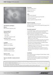
3.1 Front panel<br />
3.1.1 Controls<br />
1 STANDBY – The STANDBY button switches the unit<br />
between standby and active. The color of the LED above the<br />
switch indicates the status:<br />
Amber = Unit is in standby<br />
Unlit = Unit is active<br />
2<br />
USB – A USB communications port (for future use)<br />
3.1.2 Indicators<br />
3 SYSTEM STATUS – The SYSTEM STATUS LED indicates the<br />
condition of the unit:<br />
Green = Normal operation<br />
Red = Fault condition<br />
4 AMP OUTPUTS – These LEDs work in pairs (1 and 2, 3 and<br />
4) and indicate the operating status of the four amplifier output<br />
3.0 <strong>E4</strong> Hardware Description<br />
23 of 80<br />
channels:<br />
Green = Normal operation<br />
Red = Fault condition<br />
Unlit = No signal<br />
4<br />
5<br />
5 AUDIO SOURCES – These LEDs indicate the operating<br />
status of the four input sources:<br />
Green = Good signal<br />
Amber = Low signal<br />
Red = Signal clipping<br />
Unlit = No signal<br />
6<br />
DIRECT INPUT – The color of this LED indicates the condition<br />
of the source connected to the DIRECT IN/CONTROL connector<br />
on the rear panel.<br />
Amber = Active bypass<br />
Unlit = Normal operation<br />
3<br />
6<br />
1<br />
2
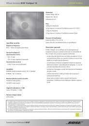
3.2 Rear panel<br />
3<br />
5<br />
1<br />
SENSE MICROPHONES<br />
ZONE 1 ZONE 2 ZONE 3 ZONE 4<br />
WALL PLATE CONNECTIONS<br />
1<br />
3<br />
LINE 1 LINE 2<br />
AUX MIC/<br />
LINE 3<br />
REMOT E<br />
ON/OFF<br />
3.2.1 <strong>System</strong> controls<br />
ZONE 4<br />
LINE OUT<br />
S<br />
PAGE/ MIC/<br />
LINE 4<br />
SENSE MICROPHONES – Input connectors for sensing<br />
microphones used with the Auto Volume feature. See the Auto<br />
Volume Kit.<br />
RS-232 – Standard RS-232 communications port. Provides<br />
a communications interface for a PC running <strong>FreeSpace</strong> ®<br />
1<br />
2<br />
Installer software. The Installer software is used to configure<br />
the <strong>E4</strong> hardware.<br />
3 WALL PLATE CONNECTIONS – Input connectors for Standard,<br />
Auto Volume, and Paging Zone user interfaces.<br />
4 REMOTE ON/OFF – An input connector for a remote<br />
STANDBY switch.<br />
3.2.2 Audio source inputs<br />
2<br />
4<br />
4<br />
AUDIO SOURCE<br />
DIRECT / IN<br />
CONTROL<br />
5 LINE 1/LINE 2 – Unbalanced audio inputs<br />
AUX MIC/LINE 3 – Balanced audio input with phantom power<br />
PAGE/MIC/LINE 4 – Balanced audio input with phantom power<br />
DIRECT IN/CONTROL – Balanced (DSP bypass at max. power)<br />
7<br />
RS232<br />
12V<br />
3.0 <strong>E4</strong> Hardware Description<br />
2<br />
8<br />
MUSIC ON<br />
HOLD/<br />
PBX OUT<br />
PTT PTT<br />
24 of 80<br />
®<br />
LISTED 917D<br />
AUDIO<br />
EQUIPMENT<br />
USE ONLY CLASS 2 WIRING<br />
ZONE OUT<br />
1 2<br />
ZONE OUT<br />
3 4<br />
TüV Rheinland<br />
geprüfte<br />
Sicherheit<br />
This device complies with part 15 of the FCC rules. Operation is<br />
subject to the following conditions: (1)This device may not cause<br />
harmful interference and (2)this device must accept any interference<br />
received, including interference which may cause undesired operation.<br />
Complies with Canadian ICES-003 Class A Spec.<br />
3.2.3 Amplifier outputs<br />
6<br />
6<br />
CONNECTOR<br />
ORIENTATION<br />
ZONE OUT 1/2/3/4 – Speaker connections for four zones<br />
Installer’s Note: Please notice the polarity markings when<br />
wiring speaker cables to the ZONE OUT connectors.<br />
CAUTION: DO NOT ground the minus (–) terminals.<br />
ZONE 4 LINE OUT – A line-level output that duplicates the<br />
program material from LINE 4. May be used to feed another<br />
amplifier installed for a large zone. The 12V control output is used<br />
to connect to <strong>Bose</strong> ® 7<br />
amplifier sequence inputs.<br />
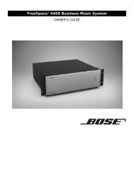
8 MUSIC ON HOLD/PBX OUT – An audio output used to<br />
provide music input to a PBX system<br />
3.2.4 AC power<br />
RISK OF ELECTRICA L SHOCK<br />
DO NOT OPEN<br />
OUTPUT<br />
VOLTAGE<br />
70V 100V<br />
DO NOT SWITCH<br />
WHILE POWER IS ON<br />
RISQUE DE CHOC ELECTRIQUE<br />
NE PAS OUVRI R<br />
<strong>FreeSpace</strong> <strong>E4</strong> <strong>Series</strong> <strong>II</strong><br />
400 Watt <strong>System</strong> Electronics<br />
<strong>Bose</strong> Corporation, Framingham, MA 01701-9168<br />
Made in the U.S.A.<br />
9 OUTPUT VOLTAGE – Sets the ZONE OUT lines to 70/100V.<br />
Set fuse box to 100/120V for 70V; 220/240V for 100V<br />
10<br />
POWER ON/OFF – Switches AC power on or off<br />
11 Fuse box – Configures the <strong>E4</strong> for 100/120V or 220/240V. Set<br />
OUTPUT VOLTAGE to 70V for 100/120V; 100V for 220/240V.<br />
12<br />
AC line cord jack – AC line voltage input<br />
9<br />
ON<br />
POWER<br />
100/120V~AC T6.25A, L250V<br />
220/240V~AC T3.15A, L250V<br />
50/60H z<br />
300W MAX<br />
12<br />
10<br />
OFF<br />
11
4.1 Introduction<br />
This section provides instructions for installing the <strong>FreeSpace</strong> ®<br />
<strong>E4</strong> system hardware on a tabletop or in a rack.<br />
4.2 Included accessories<br />
The following accessories are shipped with the <strong>E4</strong> unit in the<br />
<strong>FreeSpace</strong> <strong>E4</strong> <strong>System</strong> Accessory Kit (PC030105).<br />
2-terminal input connectors (6) – For wiring<br />
Auto Volume mics to the<br />
SENSE MICROPHONES jacks<br />
3-terminal input connectors (2) – For wiring<br />
equipment to the AUX MIC/LINE 3 jacks<br />
4-terminal input connectors (3) – For wiring<br />
equipment to the ZONE 4 LINE OUT,<br />
PAGE/MIC/LINE 4, and<br />
DIRECT IN/CONTROL jacks<br />
2-terminal output connectors (5) – For wiring<br />
speaker cables to the ZONE OUT jacks<br />
Rubber feet (4) – For installing the <strong>E4</strong> unit on<br />
a level surface<br />
Replacement voltage label (2) – Used on<br />
the OUTPUT VOLTAGE selection switch<br />
<strong>FreeSpace</strong> Installer software CD –<br />
Contains application software for programming<br />
the <strong>E4</strong> system<br />
4.0 Hardware Installation<br />
25 of 80<br />
4.3 Placement guidelines<br />
Place the <strong>E4</strong> unit where it is protected from heat and allowed<br />
adequate ventilation.<br />
Place the <strong>E4</strong> unit away from direct heat sources, such as heating<br />
vents and radiators.<br />
Make sure that air can circulate freely behind, beside, and<br />
above the unit. Allow six inches on all sides.<br />
Installer’s Note: Do not allow the chassis to exceed the<br />
maximum operating temperature of 50° C (122° F). Be aware<br />
of conditions in an enclosed rack that may increase the temperature<br />
above room-ambient conditions.<br />
4.4 Shelf mounting the <strong>E4</strong> unit<br />
The <strong>E4</strong> unit is ideal for shelf mounting. The included accessory kit<br />
contains four rubber feet for the bottom of the <strong>E4</strong> chassis. The<br />
rubber feet will protect the surface on which the <strong>E4</strong> unit is<br />
installed and help prevent movement of the <strong>E4</strong> unit. Be sure to<br />
follow the “Placement <strong>Guide</strong>lines” previously described when<br />
choosing a location for the <strong>E4</strong> unit.
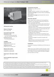
4.5 Rack mounting the <strong>E4</strong> unit<br />
Required accessory: <strong>FreeSpace</strong> ® <strong>E4</strong> <strong>System</strong> Rack Mount Kit<br />
(PC029858)<br />
The <strong>E4</strong> unit requires three 1.75" (4.4 cm) rack space units with a<br />
16" (40.6 cm) inside depth (including the rear supports). When<br />
mounting, use four screws with washers to prevent marring the<br />
front panel. Neoprene rubber washers are a good choice<br />
because they grip the screw head and prevent the screws from<br />
backing out from vibration or during transportation.<br />
Installer’s Note: If the <strong>E4</strong> unit is to be transported while<br />
mounted in a rack, be advised that the rear of the <strong>E4</strong> unit<br />
must be mechanically supported. Install a shelf under the unit<br />
or use brackets in such a way as to support the rear of the<br />
unit. Failure to use proper mounting hardware may result in<br />
damage to the <strong>E4</strong> unit during transport.<br />
4.0 Hardware Installation<br />
Rack ears (8) #8-32 x 1/2 in<strong>FreeSpace</strong><br />
26 of 80<br />
<strong>FreeSpace</strong><br />
<strong>Business</strong> <strong>Music</strong> <strong>System</strong><br />
<strong>Business</strong> <strong>Music</strong> <strong>System</strong><br />
AMP OUTPUTS<br />
1 2 3 4<br />
AUDIO SOURCES<br />
1 2 3 4<br />
Attaching rack ears to the <strong>E4</strong> chassis<br />
AMP OUTPUTS<br />
1 2 3 4<br />
AUDIO SOURCES<br />
1 2 3 4<br />
SYSTEM<br />
STATUS<br />
DIRECT<br />
INPUT<br />
Attaching the <strong>E4</strong> chassis to the rack<br />
(mounting screws not provided)<br />
STANDBY<br />
USB<br />
SYSTEM<br />
STATUS<br />
DIRECT<br />
INPUT<br />
STANDBY<br />
USB
4.6 Installing accessories<br />
4.6.1 Sensing microphones<br />
Required accessory:<br />
<strong>FreeSpace</strong> ® <strong>E4</strong> <strong>System</strong> Auto Volume Mic Kit [PC029859 (U.S.),<br />
PC029860 (Euro)]<br />
Wall plate-microphone<br />
assembly<br />
Microphone installation:<br />
The wall plate-microphone assembly can be installed using a<br />
junction box, or the microphone can be removed from the wall<br />
plate and mounted directly on a flat surface.<br />
Recommended wire length:<br />
Up to 2000 feet (610 m) max., 24 AWG (0.2 mm2 ) shielded twisted<br />
pair (shield tied to minus at <strong>E4</strong>, floated at sense mic).<br />
Painting:<br />
Before painting the wall<br />
plate, install the supplied<br />
temporary plug<br />
over the microphone<br />
opening. Remove the<br />
plug when finished.<br />
Mounting locations:<br />
For mounting instructions, see “Mounting guidelines for sensing<br />
microphones” on page 15.<br />
4.0 Hardware Installation<br />
Paint plug<br />
(2) Wire nuts<br />
(2) #6-32 (3 mm) screws<br />
Junction box installation Surface mounted mic<br />
27 of 80<br />
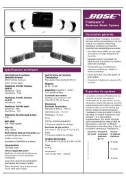
4.6.2 User interfaces<br />
Required accessory: <strong>FreeSpace</strong> <strong>E4</strong> <strong>System</strong> User Interface Kit<br />
[PC029856 (U.S.), PC029857 (Euro)] or<br />
<strong>FreeSpace</strong> <strong>E4</strong> Auto Volume Interface Kit<br />
[PC030101 (U.S.), PC030102 (Euro)] or<br />
<strong>FreeSpace</strong> <strong>E4</strong> <strong>System</strong> Page Interface Kit<br />
[PC030103 (U.S.), PC030104 (Euro)]<br />
A<br />
Wall plate<br />
Required additional equipment (not supplied):<br />
E<br />
RJ45<br />
connector<br />
Assembly:<br />
D<br />
A<br />
B<br />
B<br />
Keypad<br />
F<br />
Cat 5 cable<br />
(with 4 twisted pairs)<br />
C<br />
F<br />
C<br />
Back plate<br />
D<br />
(2) #6 x 32 / (2) M4 x 20 mm<br />
G<br />
G<br />
Single-gang<br />
electrical box<br />
SENSE MICROPHONES<br />
ZONE 1 ZONE 2 ZONE 3 ZO<br />
WALL PLATE CONNECTIONS<br />
1<br />
2<br />
3<br />
LINE 1 LINE 2<br />
4<br />
REMOT<br />
ON/OF<br />
AUDIO SOU<br />
AUX MIC/<br />
LINE 3
Keypad schematic:<br />
LED<br />
LED<br />
LED<br />
+5VD<br />
D1<br />
R1<br />
562<br />
S1 Source 1<br />
+5VD<br />
S2 Source 2<br />
+5VD<br />
D2<br />
R2<br />
562<br />
D3<br />
R3<br />
562<br />
S3 Source 3<br />
.33µF C7<br />
+5VD<br />
1 2 3 4 5 6 7 8<br />
Recommended cable lengths:<br />
One wall plate<br />
using CAT 5<br />
Two wall plates<br />
using CAT 5<br />
<strong>E4</strong><br />
<strong>E4</strong><br />
4.0 Hardware Installation<br />
LED<br />
LED<br />
LED<br />
+5VD<br />
D6<br />
R6<br />
562<br />
S6 Volume Up<br />
+5VD<br />
D5<br />
R5<br />
562<br />
S5 Volume Down<br />
S4<br />
+5VD<br />
D4<br />
R4<br />
562<br />
2000 ft (610 m) max.<br />
1300 ft (396 m) max.<br />
Mute<br />
or<br />
Auto Volume<br />
On/off<br />
28 of 80<br />
User interface wiring:<br />
Installer’s Note: Use only standard ethernet (Cat 5) cable to<br />
connect the user interface to the <strong>E4</strong> unit. DO NOT use crossover<br />
(XOV) cables.<br />
WALL PLATE<br />
CONNECTOR BLOCK<br />
POS 1<br />
POS 2<br />
POS 3<br />
POS 4<br />
POS 5<br />
POS 6<br />
POS 7<br />
POS 8<br />
<strong>E4</strong> RJ45<br />
PIN 1-8<br />
PIN 1<br />
PIN 2<br />
PIN 3<br />
PIN 4<br />
PIN 5<br />
PIN 6<br />
PIN 7<br />
PIN 8<br />
For operating information, see “User Interface Operation” on<br />
page 59.
4.7 <strong>System</strong> wiring<br />
Installer’s Note: Disconnect the <strong>E4</strong> unit from the AC<br />
(mains) power before making any input/output connections.<br />
4.7.1 Auto volume microphone inputs<br />
Connect each sensing microphone to the SENSE MICRO-<br />
PHONES jacks on the <strong>E4</strong> rear panel.<br />
4.7.2 Serial data communications<br />
Connect your PC to the <strong>E4</strong> unit using a straight-wired serial data<br />
cable (DB9 male to DB9 female).<br />
RS232 port pinout<br />
4.0 Hardware Installation<br />
SENSE MICROPHONE S<br />
ZONE 1 ZONE 2 ZONE 3 ZONE 4<br />
WALL PLATE CONNECTIONS<br />
1<br />
3<br />
LINE 1<br />
2<br />
4<br />
LINE 2<br />
AUX MIC/<br />
LINE 3<br />
REMOTE<br />
ON/O F<br />
AUDIO SOURCE<br />
ZON<strong>E4</strong><br />
LINE OUT<br />
S<br />
PAGE/ MIC/<br />
LIN<strong>E4</strong><br />
RS232<br />
12V<br />
MUSIC<br />
HOL<br />
PBX O<br />
DIRECT IN /<br />
CONTROL<br />
PTT P<br />
29 of 80<br />
4.7.3 User interface connections<br />
Connect the user interface from each zone to the appropriate<br />
WALL PLATE CONNECTION jack.<br />
Installer’s Note: Only use standard ethernet (Cat 5) cable<br />
to connect the user interface to the <strong>E4</strong> unit. DO NOT use<br />
crossover (XOV) cables.<br />
SENSE MICROPHONE S<br />
ZONE 1 ZONE 2 ZONE 3 ZONE 4<br />
WALL PLATE CONNECTIONS<br />
REMOTE<br />
ON/O F<br />
ZON<strong>E4</strong><br />
LINE OUT<br />
DIRECT IN /<br />
CONTROL<br />
4.7.4 Remote standby switch<br />
If you are installing a remote standby switch, connect it to the<br />
REMOTE ON/OFF input.<br />
Remote Standby<br />
Switch<br />
Normally Open<br />
Switch (latching)<br />
1<br />
3<br />
LINE 1<br />
2<br />
4<br />
LINE 2<br />
AUDIO SOURCE<br />
AUX MIC/<br />
LINE 3<br />
S<br />
PAGE/ MIC/<br />
LIN<strong>E4</strong><br />
RS232<br />
12V<br />
MUSIC ON<br />
HOLD/<br />
PBX OUT<br />
PTT PTT<br />
<strong>E4</strong><br />
REMOTE ON/OFF
4.7.5 LINE 1/LINE 2 source input<br />
Audio sources can be connected to the LINE 1 and LINE 2 inputs<br />
using one of the following cable types.<br />
Source Connector E-4 LINE 1/LINE 2<br />
RCA<br />
XLR<br />
T<br />
Phone<br />
Plug<br />
(Balanced)<br />
S<br />
1 2<br />
3<br />
T S<br />
Phone<br />
Plug<br />
(Unbalanced)<br />
T R S T<br />
S<br />
T<br />
1<br />
3<br />
2<br />
4.0 Hardware Installation<br />
R<br />
S<br />
S<br />
T<br />
S<br />
S<br />
S<br />
S<br />
T<br />
T<br />
T<br />
T<br />
30 of 80<br />
4.7.6 AUX MIC/LINE 3 source input<br />
A microphone or an audio source can be connected to the MIC/<br />
LINE 3 input using one of the following cable types.<br />
Source Connector E-4 AUX MIC/LINE 3<br />
RCA<br />
XLR<br />
T<br />
S<br />
1 2<br />
3<br />
Phone<br />
Plug<br />
T R S T<br />
(Balanced)<br />
Phone<br />
Plug<br />
T S<br />
(Unbalanced)<br />
S<br />
1<br />
3<br />
T<br />
2<br />
S<br />
R<br />
S<br />
T
4.7.7 PAGE/MIC/LINE 4 source input<br />
A microphone or an audio source can be connected to the PAGE/<br />
MIC/LINE 4 input using one of the following cable types.<br />
Source Connector E-4 PAGE/MIC/LINE 4<br />
RCA<br />
XLR<br />
T<br />
1<br />
S<br />
3<br />
Phone<br />
Plug<br />
T R S T<br />
(Balanced)<br />
Phone<br />
Plug<br />
T S<br />
(Unbalanced)<br />
Normally<br />
Open Switch<br />
(latching)<br />
2<br />
S<br />
T<br />
1<br />
3<br />
2<br />
S<br />
R<br />
S<br />
T<br />
4.0 Hardware Installation<br />
PTT<br />
PTT<br />
PTT<br />
PTT<br />
PTT<br />
31 of 80<br />
4.7.8 DIRECT IN/CONTROL source input<br />
A microphone or an audio source can be connected to the<br />
DIRECT IN input using one of the following cable types. The control<br />
(PTT) input requires a normally open switch.<br />
Source Connector E-4 DIRECT IN/CONTROL<br />
RCA<br />
XLR<br />
T<br />
1<br />
S<br />
3<br />
Phone<br />
Plug<br />
T R S T<br />
(Balanced)<br />
Phone<br />
Plug<br />
T S<br />
(Unbalanced)<br />
Normally<br />
Open Switch<br />
(latching)<br />
2<br />
S<br />
T<br />
1<br />
3<br />
2<br />
S<br />
R<br />
S<br />
T<br />
PTT<br />
PTT<br />
PTT<br />
PTT<br />
PTT
4.7.9 Amplifier ZONE OUT outputs<br />
Speaker systems in up to four zones can be connected to the<br />
ZONE OUT amplifier outputs.<br />
Installer’s Note: Please notice the polarity markings on<br />
the ZONE OUT 1-4 connectors. Wire each connection as<br />
shown, using the 2-terminal output connector from the<br />
accessory kit.<br />
Installer’s Note: DO NOT<br />
ground the minus (–) side of<br />
the line.<br />
1. Install a two-terminal<br />
output connector<br />
(supplied) on the<br />
speaker cable from<br />
each zone.<br />
2. Plug the speaker cable connectors into the appropriate<br />
ZONE OUT jack.<br />
Installer’s Note: Be sure to position the cable connector in<br />
the correct orientation for the ZONE OUT jacks: Screw heads<br />
face upward for ZONE OUT 1 and 2 jacks, screw heads face<br />
downward for ZONE OUT 3 and 4 jacks.<br />
USE ONLY CLASS WIRING 2<br />
ZONE OUT<br />
1 2<br />
CONNECTOR<br />
ORIENTATION<br />
®<br />
LISTED 917D<br />
AUDIO<br />
EQUIPMENT<br />
ZONE OUT<br />
3 4<br />
This device complies with part 15 of the FCC rules. Operation is<br />
subject to the following conditions: (1)This device may not cause<br />
harmful interference and (2)this device must accept any interference<br />
received,including interference which may cause undesired operation.<br />
Complies with Canadian ICES-003 Class A Spec.<br />
TüV Rheinland<br />
geprüfte<br />
Sicherheit<br />
4.0 Hardware Installation<br />
USE ONLY CLASS 2 WIRING<br />
ZONE OUT<br />
1 2<br />
CONNECTOR<br />
ORIENTATION<br />
RISK OF ELECTRICAL SHOCK<br />
DO NOT OPEN<br />
OUTPUT<br />
VOLTAGE<br />
70V 100V<br />
+<br />
DO NOT SWITCH<br />
WHILE POWER IS ON<br />
<strong>Bose</strong> Corporation F<br />
M<br />
ZONE OUT<br />
3 4<br />
–<br />
RISQUE DE CHOC ELECTRIQUE<br />
NE PAS OUVRIR<br />
100/120V~AC T6.25A, L250V<br />
220/240V~AC T3.15A, L250V<br />
50/60Hz<br />
300W MAX<br />
<strong>FreeSpace</strong> Model E-4<br />
400 Watt <strong>System</strong> Ele<br />
ON<br />
POWER<br />
OFF<br />
32 of 80<br />
4.7.10 Output voltage setting (70/100V)<br />
Check the OUTPUT VOLTAGE switch setting and change if<br />
needed.<br />
OUTPUT<br />
VOLTAGE<br />
70V 100V<br />
DO NOT SWITCH<br />
WHILE POWER IS ON<br />
Installer’s Note: Disconnect power from the <strong>E4</strong> unit before<br />
changing the OUTPUT VOLTAGE setting.<br />
To change the setting to 70V or 100V, remove the label,<br />
change the switch setting and replace the label. Additional<br />
labels are supplied in the accessory kit.<br />
Installer’s Note: Changing this setting requires a corresponding<br />
change to the fuse box configuration: 70V is<br />
selected for 100-120VAC; 100V is selected for 220-240VAC.
4.7.11 ZONE 4 LINE OUT output<br />
The ZONE 4 LINE OUT jack provides a line-level output that<br />
duplicates the program material on LINE 4. This may be used to<br />
feed another <strong>Bose</strong> ® amplifier installed for a large zone. The 12V<br />
control output is used to connect to <strong>Bose</strong> amplifier sequence<br />
inputs.<br />
Source Connector E-4 ZONE 4 LINE OUT<br />
RCA<br />
XLR<br />
T<br />
1<br />
S<br />
3<br />
Phone<br />
Plug<br />
(Balanced)<br />
T R S T<br />
Phone<br />
Plug<br />
T S<br />
(Unbalanced)<br />
Control Signal<br />
2<br />
<strong>Bose</strong> 1600, 1800 or M2150 Amplifier<br />
S<br />
T<br />
1<br />
3<br />
2<br />
S<br />
R<br />
S<br />
T<br />
4.0 Hardware Installation<br />
12V<br />
12V<br />
12V<br />
12V<br />
12V<br />
33 of 80<br />
4.8 AC power connections<br />
Installer’s Note: The fuse box configuration must be coordinated<br />
with the 70/100V OUTPUT VOLTAGE setting: 70V<br />
should be selected for 100-120VAC; 100V should be selected<br />
for 220-240VAC.<br />
Fuse box configuration<br />
The fuse box is configured at the factory according to the specifications<br />
of your order. Should you need to replace the fuse, follow<br />
these steps:<br />
1. Using a thin screwdriver blade, open the fuse box. Pull out<br />
the drawer and remove the fuse.<br />
Voltage<br />
selection<br />
indicator<br />
2. Insert a new fuse of the same type and rating into the fuse<br />
box drawer.<br />
Fuse<br />
3. Slide the fuse box drawer back into the fuse box.<br />
AC power cord receptacle<br />
Insert the proper power cord for the voltage used in your region.<br />
Power cord<br />
receptacle
<strong>Bose</strong> ® Product Sales Conditions<br />
Limited Warranty Policy<br />
and<br />
Conditions of Sale<br />
<strong>Bose</strong> Corporation<br />
The Mountain<br />
Framingham, MA 01701<br />
What is covered:<br />
All parts defective in material and workmanship. This limited<br />
warranty for the <strong>Bose</strong> Freespace ® <strong>E4</strong> system (“system”) covers<br />
the functionality of the system for its normal, intended use as<br />
specified in the Owner’s <strong>Guide</strong> and does not cover a malfunction<br />
that has resulted from improper or unreasonable use or maintenance,<br />
accident, excess moisture, improper packing,<br />
lightning, power surges, or unauthorized tampering, alteration or<br />
modification while not under the control of <strong>Bose</strong>. <strong>Bose</strong> systems<br />
are not designed to be used in every environment, so please<br />
review your Owner’s <strong>Guide</strong>.<br />
WHERE PERMITTED, THE PROVISIONS OF THIS LIMITED<br />
WARRANTY ARE IN LIEU OF ANY OTHER WRITTEN<br />
WARRANTY, WHETHER EXPRESS OR IMPLIED, WRITTEN OR<br />
ORAL, INCLUDING ANY WARRANTY OF MERCHANTABILITY<br />
OR FITNESS FOR A PARTICULAR PURPOSE.<br />
For how long:<br />
In countries where the duration of the warranty is not determined<br />
by statute, the <strong>Bose</strong> Limited Warranty lasts five years from the<br />
purchase date. For countries where minimum warranty terms are<br />
determined by statute, the warranty term is the longer of the<br />
statutory period or the term listed above.<br />
What we will do:<br />
We will repair or replace any defective parts within a reasonable<br />
period of time and free of charge.<br />
How you can obtain warranty service:<br />
1. You can ship the system to either a <strong>Bose</strong> Service Agency or to<br />
<strong>Bose</strong> directly with a proof of purchase from an authorized dealer.<br />
Please:<br />
A. Properly and carefully pack the product for shipping. If you<br />
need a carton for shipping, contact <strong>Bose</strong> for a new carton.<br />
B. Label and ship the product to the appropriate <strong>Bose</strong><br />
location.<br />
C. Please contact <strong>Bose</strong> to get a return reference number.<br />
Place this number prominently on the outside of the carton.<br />
2. You can return the system with proof of purchase from an<br />
authorized dealer to a <strong>Bose</strong> Service Agency or directly to<br />
<strong>Bose</strong>. Proof of purchase is not required where it is excluded<br />
by statute.<br />
77 of 78<br />
Other Rights:<br />
EXCLUSIVE REMEDY:<br />
THIS LIMITED WARRANTY IS FULLY TRANSFERABLE<br />
PROVIDED THAT THE CURRENT OWNER FURNISHES THE<br />
ORIGINAL PROOF OF PURCHASE FROM AN AUTHORIZED<br />
BOSE DEALER. THE MAXIMUM LIABILITY OF BOSE SHALL<br />
NOT EXCEED THE ACTUAL PURCHASE PRICE PAID BY YOU<br />
FOR THE PRODUCT. IN NO EVENT SHALL BOSE BE LIABLE<br />
FOR SPECIAL, INCIDENTAL, CONSEQUENTIAL OR INDIRECT<br />
DAMAGES. SOME PLACES DO NOT ALLOW LIMITATIONS ON<br />
THE EXCLUSION OR LIMITATION OF RELIEF, SPECIAL,<br />
INCIDENTAL, CONSEQUENTIAL OR INDIRECT DAMAGES OF<br />
THE LIMITATION OF LIABILITY TO SPECIFIED AMOUNTS, SO<br />
THE ABOVE LIMITATIONS OR EXCLUSIONS MAY NOT APPLY<br />
TO YOU.<br />
OTHER CONDITIONS:<br />
FOR YOUR BENEFIT, WE RECOMMEND THAT YOU RECORD<br />
YOUR SERIAL NUMBERS(S), FOUND ON THE PRODUCT(S),<br />
AND OTHER PURCHASE INFORMATION, AND KEEP IT WITH<br />
YOUR PERSONAL RECORDS ALONG WITH PROOF OF<br />
PURCHASE. IF NECESSARY, THIS INFORMATION WILL<br />
ALLOW US TO BETTER SERVE YOUR NEEDS.<br />
THIS LIMITED WARRANTY GIVES YOU SPECIFIC RIGHTS<br />
SUBJECT TO SPECIFIED CONDITIONS. YOU MAY ALSO HAVE<br />
OTHER LEGAL RIGHTS WHICH APPLY TO THE PRODUCT<br />
YOU HAVE ACQUIRED. THESE LEGAL RIGHTS VARY FROM<br />
STATE TO STATE OR COUNTRY TO COUNTRY. SOME PLACES<br />
DO NOT ALLOW THE EXCLUSION, RESTRICTION OR MODIFI-<br />
CATION OF CERTAIN IMPLIED RIGHTS OR THEIR EFFECT. IN<br />
THOSE SITUATIONS THIS LIMITED WARRANTY WILL ONLY<br />
APPLY TO THE EXTENT THAT THE APPLICABLE LAW ALLOWS.<br />
OTHER LAWS PROVIDE YOU WITH A STATUTORY CLAIM<br />
AGAINST THE SELLER.<br />
The laws of your state or country may provide you with legal<br />
claims against the seller or manufacturer of this product. The<br />
Limited Warranty does not affect those rights.<br />
Remedies:<br />
The provisions of this limited warranty are in lieu of any other<br />
warranties or conditions, except those provided by law. This<br />
Limited Warranty does not affect any legal rights provided to you<br />
by law and does not preclude any legal remedy you may have<br />
under the law.<br />
This Limited Warranty is fully transferable provided that the<br />
current owner furnishes the original proof of purchase from an<br />
authorized <strong>Bose</strong> dealer.<br />
This Limited Warranty is void if the label bearing the serial<br />
number has been removed or defaced.
78<br />
©2004 <strong>Bose</strong> Corporation, The Mountain,<br />
Framingham, MA 01701-9168 USA<br />
279145 AM Rev.00 CCM-000922