W. Richard Bowen and Nidal Hilal 4
W. Richard Bowen and Nidal Hilal 4
W. Richard Bowen and Nidal Hilal 4
- No tags were found...

You also want an ePaper? Increase the reach of your titles
YUMPU automatically turns print PDFs into web optimized ePapers that Google loves.
214 7. MICRO/NANOENgINEERINg ANd AFM FOR CELLULAR SENSINg<br />
<strong>and</strong> appropriate physiological conditions (medium temperature <strong>and</strong> pH).<br />
Although advances in cell immobilisation <strong>and</strong> AFM imaging modes now<br />
permit soft, live cells to be imaged, the process remains far from trivial [74].<br />
For living cell imaging, an environmental control chamber with suitable<br />
medium is essential to keep cells alive <strong>and</strong> viable. When imaging<br />
in contact mode, cantilevers with the lowest spring constants (0.003–<br />
0.06 N m �1 ) operating with a small loading force (�1 nN) are preferred.<br />
Following these basic considerations, it is possible to successfully image<br />
live cells. Figure 7.9(a)–(f) show height <strong>and</strong> error images of live 3T3 cells<br />
on a fibronectin-coated glass slide <strong>and</strong> a fibronectin-coated PDMS microgrooved<br />
substrate. A well-spread cell morphology with fibrous cytoskeleton<br />
structures can be seen clearly in Figure 7.9(a) in comparison to the<br />
restrained morphology of the cell on a flat PDMS substrate (Figure 7.9(c)<br />
<strong>and</strong> (d)). This can be further demonstrated by quantitative analysis of the<br />
cell height <strong>and</strong> its projecting area. It should be noted that cells tend to<br />
detach from the PDMS substrates during imaging. All of these observations<br />
demonstrate that 3T3 fibroblasts have much weaker adhesion to<br />
soft PDMS substrates. On microstructured PDMS structures, cells tend<br />
to position their nucleus in the trough of the channel, close to one edge<br />
<strong>and</strong> mostly attach filopodia to the upper surfaces (Figure 7.9(e) <strong>and</strong> (f)).<br />
This gives rise to a preferred cell alignment along the channel length, as<br />
discussed earlier. Thus, AFM imaging provides a quantitative <strong>and</strong> high<br />
resolution approach to studying the behaviour of living cells.<br />
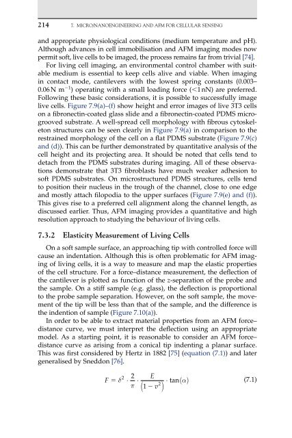
7.3.2 Elasticity Measurement of living Cells<br />
On a soft sample surface, an approaching tip with controlled force will<br />
cause an indentation. Although this is often problematic for AFM imaging<br />
of living cells, it is a way to measure <strong>and</strong> map the elastic properties<br />
of the cell structure. For a force–distance measurement, the deflection of<br />
the cantilever is plotted as function of the z-separation of the probe <strong>and</strong><br />
the sample. On a stiff sample (e.g. glass), the deflection is proportional<br />
to the probe sample separation. However, on the soft sample, the movement<br />
of the tip will be less than that of the sample, <strong>and</strong> the difference is<br />
the indention of sample (Figure 7.10(a)).<br />
In order to be able to extract material properties from an AFM force–<br />
distance curve, we must interpret the deflection using an appropriate<br />
model. As a starting point, it is reasonable to consider an AFM force–<br />
distance curve as arising from a conical tip indenting a planar surface.<br />
This was first considered by Hertz in 1882 [75] (equation (7.1)) <strong>and</strong> later<br />
generalised by Sneddon [76].<br />
F � �<br />
2<br />
2 E<br />
⋅ ⋅<br />
π<br />
2<br />
1 � v<br />
( )<br />
⋅ ( �)<br />
tan<br />
(7.1)