Sine Wave Generation Techniques
Sine Wave Generation Techniques
Sine Wave Generation Techniques

Create successful ePaper yourself
Turn your PDF publications into a flip-book with our unique Google optimized e-Paper software.
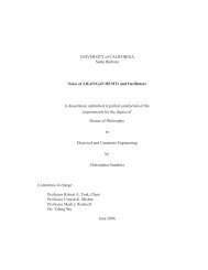
A1–A3 e ��� LM3900<br />
A4 e LH0002<br />
A5–A7 e ��� LF347<br />
T1 e UTC LS-52<br />
All diodes e 1N914<br />
� e low-TC� metal-film types<br />
TL�H�7483–5<br />
FIGURE 4� Generate high-voltage sine waves using IC-based circuits by driving a transformer in a step-up mode� You<br />
can realize digital amplitude control by replacing the LM329 voltage reference with the DAC1287�<br />
NEGATIVE RESISTANCE OSCILLATOR<br />
All of the preceding circuits rely on RC time constants to<br />
achieve resonance� LC combinations can also be used and<br />
offer good frequency stability� high Q and fast starting�<br />
In Figure 5 a negative resistance configuration is used to<br />
generate the sine wave� The Q1-Q2 pair provides a 15 mA<br />
current source� Q2’s collector current sets Q3’s peak collector<br />
current� The 300 kX resistor and the Q4-Q5 LM394<br />
matched pair accomplish a voltage-to-current conversion<br />
that decreases Q3’s base current when its collector voltage<br />
rises� This negative resistance characteristic permits oscillation�<br />
The frequency of operation is determined by the LC in<br />
the Q3-Q5 collector line� The LF353 FET amplifier provides<br />
gain and buffering� Power supply dependence is eliminated<br />
by the zener diode and the LF353 unity gain follower� This<br />
circuit starts quickly and distortion is inside 1�5%�<br />
TL�H�7483–6<br />
FIGURE 5� LC sine wave sources offer high stability and reasonable distortion levels� Transistors Q1 through Q5<br />
implement a negative-resistance amplifier� The LM329� LF353 combination eliminates power-supply dependence�<br />
4