V-752EW - Schuss Home Electronic
V-752EW - Schuss Home Electronic
V-752EW - Schuss Home Electronic

Sie wollen auch ein ePaper? Erhöhen Sie die Reichweite Ihrer Titel.
YUMPU macht aus Druck-PDFs automatisch weboptimierte ePaper, die Google liebt.
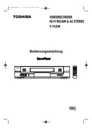
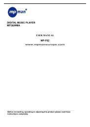
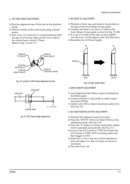
a. ACE HEAD HEIGHT ADJUSTMENT<br />
1) Run the alignment tape (Color bar) in the playback<br />
mode.<br />
2) Observe surface of the audio head using a dental<br />
mirror.<br />
3) Turn screw (C) clockwise or counterclockwise until<br />
the gap of lower tape edge and the lower edge of<br />
the control head is about 0.25mm.<br />
(Refer to Fig. 5-6 and 5-7)<br />
SCREW (A)<br />
TLIT ADJUST<br />
X-POSITION<br />
ADJUSTING SLIT<br />
SCREW (B)<br />
AZIMUTH ADJUST<br />
Fig. 5-6 Location of ACE Head Adjustment Screw<br />
VIDEO HEAD<br />
AUDIO HEAD<br />
CONTROL HEAD<br />
SCREW (C)<br />
HEIGHT ADJUST<br />
Fig. 5-7 ACE Head Height Adjustment<br />
SCREW (D)<br />
X-POSITION LOCKING<br />
0 ~ 0 .25 mm<br />
b. ACE HEAD TILT ADJUSTMENT<br />
Alignment and Adjustment<br />
1) Playback a blank tape and observe the position of<br />
the tape at the lower flange of tape guide.<br />
2) Confirm that there is no curl or wrinkle at the<br />
lower flange of tape guide as shown in Fig. 5-8 (B).<br />
3) If a curl or wrinkle of the tape occurrs, slightly<br />
turn the screw (A) tilt adjust on the ACE head ass’y.<br />
4) Reconfirm the ACE head height.<br />
WRINKLE<br />
Fig. 5-8 Tape Guide Check<br />
c. AUDIO AZIMUTH ADJUSTMENT<br />
(A) (B)<br />
1) Load alignment tape (Mono scope) and playback<br />
the 6KHz signal.<br />
2) Connect channel-1 scope probe to audio output<br />
test point (TP302).<br />
3) Adjust screw (B) to achieve maximum audio level.<br />
(See Fig. 5-6)<br />
d. ACE HEAD POSITION (X-POINT) ADJUSTMENT<br />
1) Playback the alignment tape (Color bar).<br />
2) Press the “SW713” button on Main PCB to set the<br />
adjustment mode. (See Fig. 5-2)<br />
3) Press the “5” button of remote control then adjustment<br />
is operated automatically. (See Fig. 5-1)<br />
4) Connect the CH-1 probe to TP303 (Envelope) the<br />
CH-2 probe to TP601 (H’D switching pulse) and<br />
then trigger to CH-1.<br />
5) Insert the (-) driver into the X-Point adjustment<br />
hole and adjust it so that envelope waveform is<br />
maximum.<br />
6) Turn the Power off.<br />
Toshiba 5-5<br />
(BAD)<br />
(GOOD)