V-752EW - Schuss Home Electronic
V-752EW - Schuss Home Electronic
V-752EW - Schuss Home Electronic

Sie wollen auch ein ePaper? Erhöhen Sie die Reichweite Ihrer Titel.
YUMPU macht aus Druck-PDFs automatisch weboptimierte ePaper, die Google liebt.
1. Precautions<br />
1. Be sure that all of the built-in protective devices are<br />
replaced. Restore any missing protective shields.<br />
2. When reinstalling the chassis and its assemblies, be<br />
sure to restore all pretective devices, including :<br />
control knobs and compartment covers.<br />
3. Make sure that there are no cabinet openings<br />
through which people--particularly children<br />
--might insert fingers and contact dangerous<br />
voltages. Such openings include the spacing<br />
between the picture tube and the cabinet mask,<br />
excessively wide cabinet ventilation slots, and<br />
improperly fitted back covers.<br />
If the measured resistance is less than 1.0 megohm<br />
or greater than 5.2 megohms, an abnormality exists<br />
that must be corrected before the unit is returned<br />
to the customer.<br />
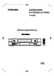
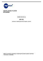
4. Leakage Current Hot Check (See Fig. 1-1) :<br />
Warning : Do not use an isolation transformer<br />
during this test. Use a leakage current tester or a<br />
metering system that complies with American<br />
National Standards Institute (ANSI C101.1,<br />
Leakage Current for Appliances), and Underwriters<br />
Laboratories (UL Publication UL1410, 59.7).<br />
5. With the unit completely reassembled, plug the AC<br />
line cord directly the power outlet. With the unit’s<br />
AC switch first in the ON position and then OFF,<br />
measure the current between a known erath<br />
ground (metal water pipe, conduit, etc.) and all<br />
exposed metal parts, including : antennas, handle<br />
brackets, metal cabinets, screwheads and control<br />
shafts. The current measured should not exceed<br />
0.5 milliamp. Reverse the power-plug prongs in the<br />
AC outlet and repeat the test.<br />
6. X-ray Limits :<br />
The picture tube is designed to prohibit X-ray<br />
emissions. To ensure continued X-ray protection,<br />
replace the picture tube only with one that is the<br />
same type as the original.<br />
Fig. 1-1 AC Leakage Test<br />
7. Antenna Cold Check :<br />
With the unit’s AC plug disconnected from the<br />
AC source, connect an electrical jumper across the<br />
two AC prongs. Connect one lead of the ohmmeter<br />
to an AC prong.<br />
Connect the other lead to the coaxial connector.<br />
8. High Voltage Limit :<br />
High voltage must be measured each time<br />
servicing is done on the B+, horizontal deflection<br />
or high voltage circuits.<br />
Heed the high voltage limits. These include the<br />
X-ray protection Specifications Label, and the<br />
Product Safety and X-ray Warning Note on the<br />
service data schematic.<br />
9. Some semiconductor (“solid state”) devices are<br />
easily damaged by static electricity.<br />
Such components are called Electrostatically<br />
Sensitive Devices (ESDs); examples include<br />
integrated circuits and some field-effect transistors.<br />
The following techniques will reduce the<br />
occurrence of component damage caused by static<br />
electricity.<br />
10. Immediately before handling any semiconductor<br />
components or assemblies, drain the electrostatic<br />
charge from your body by touching a known<br />
earth ground. Alternatively, wear a discharging<br />
Wrist-strap device. (Be sure to remove it prior to<br />
applying power--this is an electric shock<br />
precaution.)<br />
Toshiba 1-1<br />
DEVICE<br />
UNDER<br />
TEST<br />
TEST ALL<br />
EXPOSED METER<br />
SURFACES<br />
2-WIRE CORD<br />
ALSO TEST WITH<br />
PLUG REVERSED<br />
(USING AC ADAPTER<br />
PLUG AS REQUIRED)<br />
LEAKAGE<br />
CURRENT<br />
TESTER<br />
(READING SHOULD<br />
NOT BE ABOVE<br />
0.5mA)<br />
EARTH<br />
GROUND