HOLZ-ALUMINIUM – FASSADEN UND ... - Gutmann AG
HOLZ-ALUMINIUM – FASSADEN UND ... - Gutmann AG
HOLZ-ALUMINIUM – FASSADEN UND ... - Gutmann AG

Erfolgreiche ePaper selbst erstellen
Machen Sie aus Ihren PDF Publikationen ein blätterbares Flipbook mit unserer einzigartigen Google optimierten e-Paper Software.
GÜLTIG AB: 2009<br />
VALID FROM: 2009<br />
GUTMANN LARA<br />
Bausysteme <strong>HOLZ</strong>-<strong>ALUMINIUM</strong> <strong>–</strong> <strong>FASSADEN</strong> <strong>UND</strong> WINTERGÄRTEN<br />
Building Systems WOOD <strong>ALUMINIUM</strong> <strong>–</strong> CURTAIN WALLS AND CONSERVATORIES
Aluminium shaped by GUTMANN<br />
Vor mehr als sieben Jahrzehnten als Leichtmetall-Drahtwerk<br />
im fränkischen Weißenburg gegründet, hat sich GUTMANN<br />
heute zu einer weltweit agierenden Unternehmensgruppe mit<br />
über 1.200 Mitarbeitern entwickelt. Dazu gehören die Firmen<br />
<strong>Gutmann</strong> <strong>AG</strong>, Gartner Extrusion GmbH, NordAlu GmbH und<br />
die <strong>Gutmann</strong> Aluminium Draht GmbH.<br />
Die GUTMANN GRUPPE gehört zur griechischen Alco Gruppe.<br />
Die Muttergesellschaft ist die börsennotierte Alco Hellas S.A.,<br />
Athen. An verschiedenen Standorten werden hochwertige Aluminiumprodukte<br />
hergestellt, die vor allem in der Baubranche, in<br />
der Auto mobilindustrie, im Maschinenbau sowie in der Elektrotechnik<br />
Maßstäbe setzen.<br />
Das GUTMANN Produktportfolio gliedert sich dabei in die<br />
Kernsegmente Bausysteme, Industrieprofi le und Spezialdrähte:<br />
Bausysteme steht für moderne Fenster-, Türen- und Fassadensysteme,<br />
die den unterschiedlichen Anforderungen von<br />
Architekten und Bauherrn in Stil und Design optimal gerecht<br />
werden. Die vielseitig einsetzbare Aluminium-Verbundplatte<br />
GUTBOND komplettiert die Produktpalette. Industrieprofi le<br />
bürgt für hochwertige Halbzeug- und Fertigprodukte für die<br />
verschiedensten industriellen Anforderungen und in der Sparte<br />
Spezialdrähte hat sich GUTMANN weltweit als Experte für<br />
gezogene Drähte und Stangen etabliert.<br />
Die Nähe zum Kunden, das außergewöhnliche Engagement der<br />
Mitarbeiterinnen und Mitarbeiter sowie die hohe Innovationskraft<br />
haben die GUTMANN GRUPPE zu einem der führenden<br />
Anbieter von hochwertigen Aluminiumprodukten gemacht und<br />
bilden gleichzeitig die solide Basis für das weitere Wachstum des<br />
leistungsfähigen Unternehmensverbundes.<br />
GUTMANN, started more than 70 years ago as a producer of<br />
light alloys and wire in the Franconian town of Weissenburg,<br />
Germany, is today an international group of companies employing<br />
over 1200 workers. It includes the companies <strong>Gutmann</strong> <strong>AG</strong>,<br />
Gartner Extrusion GmbH, NordAlu GmbH, and <strong>Gutmann</strong> Aluminium<br />
Draht GmbH.<br />
The GUTMANN GROUP belongs to the Greek Alco Group,<br />
the holding company being the listed Alco Hellas S.A., Athens.<br />
High-quality aluminium products are produced at 4 locations and<br />
they set the standard in the construction, automotive, mechanical<br />
engineering, and electrical engineering industries.<br />
The GUTMANN product portfolio covers the core segments:<br />
Building System Sections, Industrial Profi le Sections, and<br />
Specialized Wire.<br />
Building System Sections are designed for modern windows,<br />
doors, and curtain-wall systems that are optimized to the wide<br />
range of stylistic and design requirements expected by architects<br />
and builders. The versatile Aluminium Composite Panels<br />
marketed under the brand name GUTBOND complete the product<br />
range. Industrial Profi le Sections guarantee high-quality<br />
semi-fi nished and fi nished products for a wide variety of industrial<br />
requirements. In the Specialized Wire segment, GUTMANN<br />
has earned itself a global reputation as a specialist in extruded<br />
wire and rods.<br />
Customer proximity, tremendously committed employees, and<br />
high innovative power have made the GUTMANN GROUP into<br />
what it is today, and this forms a solid base for continued growth<br />
in the future.
INHALTSVERZEICHNIS<br />
CONTENT<br />
Systemübersicht<br />
System overview<br />
Verarbeitungshinweise 6-13<br />
Statik und Holzverbindung Twinloc 14-18<br />
Processing guidelines 19-26<br />
Statics and connector Twinloc 27-31<br />
Profilübersicht<br />
Profile overview 32-44<br />
Zubehör<br />
Accessories 45-53<br />
Lara GF Details<br />
Lara GF detail drawings 54-78<br />
Dachfenster S70<br />
Roof window S70 79-82<br />
Lara classic Details<br />
Lara classic detail drawings 83-102<br />
Wärmeberechnungen<br />
Heat transfer calculations 103-106<br />
Ausschreibungstexte<br />
Bidding documents 107-110<br />
Kantteile<br />
Edgings 111<br />
Technische Hinweise<br />
Technical guidelines 112-115
H O L Z <strong>–</strong> A L U M I N I U M<br />
EINE IDEALE VERBINDUNG ÜBER GENERATIONEN HINWEG<br />
Holz-Aluminium hält ein Leben lang. Die GUTMANN Systempro-<br />
file verbinden zwei Vorteile: die hohe Wärmedämmung von Holz<br />
und die Witterungsbeständigkeit von Aluminium. Eine überzeugende<br />
Kombination, die ein Leben lang hält und Kosten spart.<br />
Dreh-Kipp-Fenster und -Türen<br />
GUTMANN hat für jedes Fenster, jeden Wintergarten und jede<br />
Fassade die passende Lösung. Wählen Sie das Systemprofil, das<br />
Ihren Anforderungen und denen Ihrer Kunden am besten entspricht.<br />
Mit GUTMANN fällt die Wahl leicht.<br />
GUTMANN MIRA MIRA therm 08 BR<strong>AG</strong>A<br />
Sanierungsfenster<br />
Türen nach außen öffnend<br />
Fenster nach außen öffnend<br />
Drehflügel nach außen öffnend<br />
Seitengesteuertes Fenster<br />
Obengesteuertes Fenster<br />
Top-Schwing Fenster<br />
Topangehängtes Fenster<br />
Parallel-Schiebefenster<br />
Verbundflügel<br />
Falttüren<br />
Schwingfenster<br />
Festverglasung<br />
Hebe-/Schiebetüren<br />
Rundbogenfenster<br />
Rollladenführungsprofile und Zubehör<br />
Fensterbänke und Zubehör<br />
Kantteile<br />
Vorsatzsprosse<br />
Einspannelement für P/R-Fassade<br />
MIRA MIRA<br />
contour<br />
MIRA<br />
classic<br />
MIRA<br />
contour integral<br />
BR<strong>AG</strong>A BR<strong>AG</strong>A<br />
integral
WOOD <strong>ALUMINIUM</strong><br />
AN IDEAL CONNECTION THAT WILL LAST FOR GENERATIONS<br />
Wood-aluminium lasts a lifetime. GUTMANN system profiles<br />
combine two benefits: the highly effective insulating qualities of<br />
wood with the weather resistance of aluminium. A convincing<br />
combination that saves money and lasts a lifetime.<br />
CORA NORDWIN DECCO<br />
Kunststoff-Aluminium<br />
Plastic-Aluminium<br />
GUTMANN has the ideal solution for every window, every winter<br />
garden, and every curtain wall. Choose the system profile to<br />
best suit your needs and those of your clients. With GUTMANN<br />
you have made the right choice.<br />
Tilt & Turn windows and doors<br />
Renovation windows<br />
Doors opening outwards<br />
Window opening outwards<br />
Turn sash opening outwards<br />
Side-hinged window<br />
Top-hinged window<br />
Top-swing window<br />
Top-hung window<br />
Parallel-sliding windows<br />
Composite sash<br />
Folding doors<br />
Swing window<br />
Fixed glazing<br />
Lifting sliding door<br />
Round-arched window<br />
Rolling shutter guides and accessories<br />
Window sills and accessories<br />
Edgings<br />
Attachment crossbar<br />
Insertion window for mullion / transom curtain wall
6<br />
Verarbeitungshinweise<br />
Lara GF<br />
Allgemeines:<br />
Die nachfolgenden Verarbeitungshinweise erklären die<br />
prinzipielle Vorgehensweise bei der Herstellung und<br />
Montage von Pfosten-Riegel-Fassaden, Wintergärten und<br />
Glaswänden in Holz-Alu Bauweise. Die Angaben<br />
entsprechen unserem derzeitigen Erfahrungsstand. Die<br />
Ausführung muss nach den einschlägigen Normen und<br />
Richtlinien, den anerkannten Regeln der Technik und den<br />
unten aufgeführten Verarbeitungshinweisen erfolgen. Für<br />
Schäden, die aus unsachgemäßer Verarbeitung entstehen,<br />
übernehmen wir keine Haftung. Die Hinweise können nicht<br />
alle objektbezogenen Sonderlösungen berücksichtigen. Bei<br />
weiteren Rückfragen wenden Sie sich bitte an unsere<br />
technischen Anwendungsberater.<br />
Ausführung der Tragkonstruktion<br />
Die Konstruktion ist als Holzbauteil aus Brettschichthölzern<br />
BS 11 / GL 24 gem. DIN 1052 oder aus zugelassenen<br />
Furnierschichthölzern herzustellen. Alternativ kann das<br />
Tragwerk auch aus Stahl- oder Alu-Profilen bestehen. Die<br />
Dimensionierung ist den statischen Erfordernissen<br />
anzupassen. Es ist darauf zu achten, dass die Konstruktion<br />
an der Aufschraubfläche des Basisprofiles ebenengleich<br />
ausgeführt wird. Zur Vordimensionierung eines Sparrens<br />
kann die weiter hinten abgedruckte Tabelle verwendet<br />
werden.<br />
Verbindungen des Holztragwerks<br />
Die Verbindungen zwischen Pfosten und Riegel (bzw.<br />
Sparren und Pfette) sind so auszuführen, dass Glas-, Wind<br />
und Schneelasten ohne Verformung und Verdrehung der<br />
Konstruktion aufgenommen werden, was mit dem allgemein<br />
bauaufsichtlich zugelassenen Verbinder <strong>Gutmann</strong> Twinloc<br />
sichergestellt wird. Siehe hierzu auch die weiter hinten<br />
abgedruckte Tabelle.<br />
Schutz des Holztragwerks<br />
Die Holzkonstruktion ist als maßhaltiges Bauteil mit einem<br />
geeigneten Oberflächenschutz zu versehen um<br />
Dimensionsänderungen aufgrund Quellung und<br />
Oberflächenschäden aufgrund Feuchteeinwirkung zu<br />
vermeiden.<br />
Bei Räumen mit zu erwartender hoher Luftfeuchte<br />
empfehlen wir zur Feuchteentlastung eine mittige Nute [1]<br />
(10 x 10 mm) an der Außenseite der Holzkonstruktion zu<br />
fräsen.<br />
Befestigung der Basisprofile<br />
Die Basisprofile werden mit System-Edelstahl-<br />
Holzschrauben [2] 4 x 45 (ca. 7 Schrauben pro Meter,<br />
vorbohren) auf der Holzkonstruktion verschraubt. Im Bereich<br />
der Glasauflage-Punkte [3] (jeweils rechts und links<br />
unterhalb einer Glasscheibe) müssen pro Glasauflagepunkt<br />
5 Stck. Schrauben in korrekter Position angebracht werden.<br />
Das Basisprofil ist zum Verschrauben wechselseitig alle 150<br />
mm mit Bohrungen Ø 5 mm vorgelocht.<br />
Um das Profil genau auf Achse der Holzkonstruktion zu<br />
positionieren, wird empfohlen, Nuten [4] als Einschraubhilfe<br />
zu fräsen.<br />
Beim T-Stoß der Basisprofile werden die Riegel-Basisprofile<br />
beidseitig mit je 7 mm Abstand [5] in die Lichte der<br />
Pfosten-Basisprofile geschnitten, damit die Dichtung ohne<br />
Unterbrechung auf dem Pfosten durchlaufen kann. Wird der<br />
(19)<br />
(19)<br />
LARA<br />
Twinloc-Verbinder eingesetzt, erhöht sich der Abstand [5]<br />
auf 19 mm. Das Ende der Pfosten-Basisprofile kann auf<br />
Achse des Riegel-Basisprofils eingekürzt [6] werden, um<br />
die Wärmeverluste am Pfosten-Basisprofil zu verringern.<br />
Bei Einsatz der Dichtungen GF 50 (60) RF-E4 (zur Riegel-<br />
Entwässerung) läuft das Riegel-Basisprofil durch und das<br />
Pfosten-Basisprofil stößt mit 7 mm Abstand [5] von oben.<br />
Befestigung der Basisprofile auf Stahl<br />
Werden die Basisprofile auf eine (verzinkte) Stahl-<br />
Unterkonstruktion montiert, sind Kunststoff-Isolierbänder und<br />
Edelstahl-Schrauben M5, EN ISO 7045 zur Vermeidung von<br />
Kontaktkorrosion zu verwenden. Zur Befestigung sind in<br />
diesem Fall die gestanzten Langlöcher 5,5 x 20 mm<br />
vorgesehen.<br />
Abdichtung und Isolierung der Elementkanten<br />
Um an den Elementkanten (Fußpunkt, Ortgang, Traufe,<br />
Wandanschlüsse, etc.) hohe Luftdichtigkeit zu erreichen (z.<br />
B. für Blower-Door-Tests) sind zwischen Basisprofil und<br />
Holz-Konstruktion Abdichtungen [7] mit vorkomprimierten<br />
Dichtbändern oder Silikon einzuplanen. Das Basisprofil muss<br />
im fertig eingebauten Zustand dort auch außenseitig<br />
ausreichend wärmegedämmt [8] werden.<br />
4.0 x 45<br />
Art. Nr. 800190
Verarbeitungshinweise<br />
Lara GF<br />
Allgemeines zur Montage der inneren Dichtungen<br />
Grundsätzlich wird empfohlen, die Dichtung schon in der<br />
Werkstatt auf die vorgerichteten Elemente aufzubringen, da<br />
die Handhabung bei liegenden Elementen einfacher ist. Die<br />
Dichtungen werden mit dem Einrollwerkzeug (eingestellt auf<br />
die jeweilige Dichtungs-Breite) oder per Hand in die<br />
Aufnahmen des Basisprofils gedrückt. Wegen möglicher<br />
Abfärbungen wird empfohlen, mit Handschuhen zu arbeiten<br />
und den Kontakt mit der Holzoberfläche zu vermeiden.<br />
Dichtungssystem<br />
Der Standard-Pfosten wird in der Regel in der Ebene 3 [E3],<br />
der Standard-Riegel in der Ebene 2 [E2] ausgeführt. Falls ein<br />
Fassadenfeld nochmals unterteilt werden soll, kann die<br />
Dichtung der Ebene 1 [E1] überlappend mit der Dichtung der<br />
Ebene 2 verbunden werden. Falls das Kondensat aus dem<br />
Glasfalz nicht über den Pfostenfalz entwässert werden soll,<br />
kann mit der Dichtung der Ebene 4 [E4] am Riegel die so<br />
genannte „Riegel-Entwässerung“ ausgeführt werden. Das<br />
System “Lara GF“ ermöglicht somit in der Baubreite 50 und<br />
60 mm 4 und in der Baubreite 80 mm 3 verschiedene<br />
Dichtungsebenen.<br />
Standard-<br />
Konstruktion<br />
Eindrücken der Dichtung<br />
Die durchlaufenden Pfosten- (Sparren-) Dichtungen werden<br />
"von der Rolle" direkt auf das Basisprofil aufgebracht und<br />
entsprechend der Element-Länge abgeschnitten.<br />
Klinken der durchlaufenden Dichtung [Kd]<br />
An den T-Stößen wird die Glasanlage-Lippe der<br />
durchlaufenden Dichtung auf Breite der anstoßenden<br />
Dichtung mit dem Klinkwerkzeug in der nötigen Tiefe<br />
eingeschnitten und der Zwischenbereich abgerissen. Das<br />
Klinkwerkzeug wird hierfür auf die passende Breite und Tiefe<br />
voreingestellt. Die exakte Position der Aussparung wird<br />
dadurch hergestellt, dass die Führung des Klinkwerkzeuges<br />
auf das Basisprofil gesetzt und durch Druck mit dem<br />
Handballen die bereits montierte, durchlaufende Dichtung<br />
eingeschnitten wird.<br />
Klinken der anstoßenden Dichtung [Ka]<br />
Die anstoßende Dichtung wird mit ca. 1% Längenzugabe<br />
vorgerichtet. Bei der Längenfestlegung muss berücksichtigt<br />
werden, dass die anstoßende Dichtung die durchlaufende<br />
Dichtung um 13 mm überlappt. Die anstoßende Dichtung des<br />
T-Stoßes wird rückseitig im Abstand von 13 mm vom Ende<br />
auf die nötige Tiefe eingeschnitten und der rückseitige<br />
Bereich abgerissen.<br />
Herstellen der Dichtungsüberlappung<br />
Die (z. B. mit Spülmittelwasser) gereinigte und getrocknete<br />
Überlappung wird mit APTK-Dichtstoff [AD] und dem<br />
passenden Dichtstück [DS] am seitlichen Ende der<br />
anstoßenden Dichtung verschlossen. In die Aussparung der<br />
durchlaufenden Dichtung wird ebenfalls eine Raupe APTK-<br />
Dichtstoff [AD] angegeben und die Überlappung<br />
zusammengepresst, so dass die Glasanlage-Lippen auf einer<br />
Ebene liegen.<br />
Eindrücken<br />
der Dichtung<br />
Klinken der anstoßenden Dichtung<br />
LARA<br />
Klinken der durchlaufenden Dichtung<br />
Dichtungssystem<br />
7
8<br />
Verarbeitungshinweise<br />
Lara GF<br />
Ausführbare Glasdicken<br />
Minimale und maximale Maße der Glasdicken können<br />
nebenstehender Tabelle entnommen werden.<br />
Die Tabelle geht von äußeren Verglasungsdichtungen mit<br />
Spaltbreite 4 mm aus. Bei Einsatz von Dichtungen für<br />
Spaltbreite 6 mm sind jeweils 2 mm geringere Glasdicken<br />
ausführbar.<br />
Vorbereitung der Glasauflagermontage<br />
Am Glasauflager muss das Basisprofil, wie oben<br />
beschrieben, mit 5 Stck Schrauben befestigt werden. Die<br />
Tragfähigkeit der Pfosten-Riegel-Verbindung und die<br />
Durchbiegung des Riegels unter Glaslast sind zu beachten.<br />
Glasauflagermontage und maximale Glasgewichte<br />
Gemäß den einschlägigen Verglasungs-Richtlinien werden<br />
unterhalb jeder Glasscheibe genau 2 Stück Glasauflagen<br />
montiert. Die zulässigen Glaslasten für die Glasauflager<br />
sind der Tabelle zu entnehmen. In Abhängigkeit von der<br />
Glasdicke werden die passenden Glasauflager (siehe<br />
Tabelle) im Abstand von 90-100 mm zur Pfosten-Lichte mit<br />
je 2 Stck Schrauben B 5,5 x 22 (Art. Nr. 825522) oder<br />
B 5,5 x 38 (Art. Nr. 825538) verschraubt. Bei Einfachgläsern<br />
wird die Verklotzung direkt auf dem Schraubkanal des<br />
Basisprofils vorgenommen.<br />
Funktion des Isolators<br />
Der Isolator erfüllt 2 Funktionen:<br />
1.) Verbesserung des Wärmedämmwertes „Uf“ und damit<br />
Vermeidung von Wärmeverlusten und geringere<br />
Schwitzwasser-Neigung.<br />
2.) Kontrollierte Belüftung und Kondensat-Abführung vom<br />
Riegel- in den Pfosten-Glasfalz durch Trennung der<br />
angrenzenden Felder.<br />
Auswahl und Montage des Isolators<br />
Die Auswahl des Isolators wird in Abhängigkeit der<br />
verwendeten Glasdicke und des vorgesehenen Grundprofils<br />
getroffen. (siehe Tabelle)<br />
Der Isolator wird im Zuge der Verglasungs-Arbeiten auf die<br />
vorher montierte Dichtung aufgesteckt.<br />
Der Isolator muss spätestens 2 Monate nach Montage<br />
durch Aufbringen der durchlaufenden<br />
Verglasungsprofile vor Sonnenlicht geschützt werden,<br />
da er begrenzt UV-stabil ist.<br />
Minimale / maximale Glasdicke<br />
Glasdicke<br />
(mm)<br />
Glasauflager bei unterschiedlichen Glasdicken<br />
mit Grundprofil<br />
P2011/50,<br />
P2011/60<br />
LARA<br />
mit Grundprofil<br />
P2011/55,<br />
P2011/80<br />
sonst.<br />
Grundprofile<br />
und sichtbar<br />
geschraubte<br />
Profile<br />
6 <strong>–</strong> 8 -------------- ausführbar --------------<br />
9 <strong>–</strong> 12 ausführbar ausführbar --------------<br />
18 <strong>–</strong> 21 -------------- ausführbar --------------<br />
22 <strong>–</strong> 23 ausführbar ausführbar --------------<br />
24 <strong>–</strong> 44 ausführbar ausführbar ausführbar<br />
45 <strong>–</strong> 46 ausführbar ausführbar --------------<br />
47 <strong>–</strong> 48 ausführbar -------------- --------------<br />
Auswahl Glasauflager / maximales Glasgewicht<br />
Glasdicke Ausführung Glasauflage max. Glas-<br />
(mm)<br />
gewicht bei<br />
6 <strong>–</strong> 12 Glasauflage direkt auf das Basisprofil Glasdicke bis<br />
18 <strong>–</strong> 23 GA 26, in Eigenfertigung beschnitten bis 28 mm:<br />
24 <strong>–</strong> 28 GA 26 400 kg<br />
29 <strong>–</strong> 31 GA 34, in Eigenfertigung beschnitten bis 34 mm:<br />
32 <strong>–</strong> 36 GA 34 350 kg<br />
36 <strong>–</strong> 42 GA 44, in Eigenfertigung beschnitten bis 44 mm:<br />
42 <strong>–</strong> 46 GA 44 250 kg<br />
47 <strong>–</strong> 48 GA 44, Empfehlung:<br />
bis 48 mm:<br />
Glasklotz mit Stahleinlage verwenden 225 kg<br />
Glasdicke 6-12 mm z. B. Glasdicke 24-28 z. B. Glasdicke 29-31 mm z. B. Glasdicke 42-46 mm<br />
Auswahl Isolator<br />
Glasdicke mit Grundprofil<br />
(mm) P 2011/50, -/60 (*1) P 2011/55 P 2011/80<br />
24 <strong>–</strong> 28 IP 1 IP 2 IP 80, (*2)<br />
29 <strong>–</strong> 33 IP 2 IP 3 IP 80, (*2)<br />
34 <strong>–</strong> 38 IP 3 IP 4 IP 80, (*2)<br />
39 <strong>–</strong> 43 IP 4 IP 5 IP 80, (*2)<br />
44 <strong>–</strong> 48 IP 5 -------------- IP 80<br />
(*1) inklusive ähnliche sichtbar geschraubte Profile<br />
(*2) in Eigenfertigung beschnitten<br />
Glasdicke<br />
Grundprofil<br />
Isolator
Verarbeitungshinweise<br />
Lara GF<br />
Zuschnitt und Vorbereitung der Grundprofile<br />
(= Pressleiste bzw. Druckprofil)<br />
Die Pfosten-Grundprofile werden auf die erforderliche Länge<br />
geschnitten. Die dazwischen liegenden Riegel-Grundprofile<br />
werden beidseitig um je 3 mm kürzer als die Abdeckprofil-<br />
Lichte hergerichtet. Bei Verwendung des Grundprofils P<br />
2011/50 und P 2011/60 mit den Druckleisten-Dichtteilen<br />
wird das Grundprofil am Riegel beidseitig um je 8 mm zur<br />
Pfosten-Abdeckprofil-Lichte eingekürzt. Grundsätzlich muss<br />
durch eine evtl. zusätzliche Bohrung ∅ 6 mm sichergestellt<br />
sein, dass der Abstand der Befestigungen nicht größer als<br />
60 mm vom Rand ist.<br />
Einziehen der<br />
Verglasungsdichtung<br />
Die Verglasungsdichtungen<br />
sind mit ca. 1% Übermaß<br />
gestaucht in das Grundprofil<br />
einzuziehen. Falls das<br />
Druckleisten-Dichtteil am<br />
Riegel verwendet wird, ist der<br />
Stoß des Dichtteiles mit dem<br />
Ende der Verglasungsdichtungen<br />
mit EPDM-<br />
Klebstoff zu verkleben. Bei<br />
Ausführung ohne Dichtteil<br />
muss die Dichtung am Riegel-<br />
Grundprofil beidseitig je 3-5<br />
mm überstehen, damit nach<br />
Einbau ein geschlossener<br />
Stoß zur durchlaufenden<br />
Pfosten-Dichtung entsteht, der<br />
mit EPDM-Dichtmasse gesichert<br />
werden sollte.<br />
Druckleisten<br />
-Dichtteil<br />
Verklebung<br />
Einsatz von besonderen Verglasungsdichtungen<br />
Wenn die zum Glas hin abgeschrägten Riegelabdeckprofile<br />
(P 2016/13-55 bis -100) eingesetzt werden, ist die<br />
Riegeldichtung 7500043 einzusetzen.<br />
Bei Glas-Stößen (Wechseln) mit Silikonfugenbändern, wird<br />
der Einsatz der Silikon-Dichtung 7500042 empfohlen. Die<br />
Stöße der Fugenbänder und der Dichtung können dann mit<br />
Silikon dauerhaft verklebt werden.<br />
Vorbereitung der Montage der Grundprofile<br />
Die passenden Schrauben werden in Abhängigkeit der<br />
Glasdicke und des verwendeten Grundprofiles (siehe<br />
Tabellen) ausgewählt.<br />
Nach dem Einsetzen der Glasscheiben, die auf<br />
fachgerechte Art verklotzt und mit “Kurz-Stücken“<br />
(= ca. 15 cm-Abschnitte aus Grundprofilen mit eingezogener<br />
Dichtung, in Längsrichtung der Scheibenkante montiert)<br />
gesichert sind, werden die Grundprofile montiert.<br />
Montage der Grundprofile<br />
Die Grundprofile werden im Normalfall mit einem<br />
Anzugswert von 4.0 Nm verschraubt. Bei der<br />
Verschraubung muss auf gleichmäßigen Anpressdruck<br />
geachtet werden: Die Innendichtung muss mit genügendem<br />
Anpressdruck am Glas anliegen, die äußere<br />
Verglasungsdichtung muss gleichmäßig und ohne<br />
Verwerfung an den Schraubpunkten durchlaufen. Mit einer<br />
einfachen, selbst herzustellenden Lehre kann ausgehend<br />
von der Außenkante des Grundprofiles das herzustellende<br />
Differenzmaß zur Glasebene kontrolliert werden.<br />
LARA<br />
Auswahl Schrauben<br />
(bei Verwendung der Verglasungs-Dichtung mit 4 mm<br />
Spaltbreite)für Grundprofil P 2011/55 und P 2011/80 N:<br />
Glasdicke Art. Nr. Länge<br />
Schraube Schraube “L“<br />
6 <strong>–</strong> 7 mm 815525 25 mm<br />
8 <strong>–</strong> 12 mm 815530 30 mm<br />
18 <strong>–</strong> 20 mm 815538 38 mm<br />
21 <strong>–</strong> 22 mm 815540 40 mm<br />
23 <strong>–</strong> 24 mm 815542 42 mm<br />
25 <strong>–</strong> 27 mm 815545 45 mm<br />
28 <strong>–</strong> 31 mm 815548 48 mm<br />
32 <strong>–</strong> 33 mm 815550 50 mm<br />
34 <strong>–</strong> 35 mm 815552 52 mm<br />
36 <strong>–</strong> 38 mm 815555 55 mm<br />
39 <strong>–</strong> 40 mm 815558 58 mm<br />
41 <strong>–</strong> 42 mm 815560 60 mm<br />
43 <strong>–</strong> 44 mm 815562 62 mm<br />
45 <strong>–</strong> 46 mm 815565 65 mm<br />
für Grundprofil P 2011/50, P 2011/60, P HGF-50:<br />
Glasdicke Art. Nr. Länge<br />
Schraube Schraube “L“<br />
9 <strong>–</strong> 11 mm 815525 25 mm<br />
12 <strong>–</strong> 16 mm 815530 30 mm<br />
22 <strong>–</strong> 24 mm 815538 38 mm<br />
25 <strong>–</strong> 26 mm 815540 40 mm<br />
27 <strong>–</strong> 28 mm 815542 42 mm<br />
29 <strong>–</strong> 31 mm 815545 45 mm<br />
32 <strong>–</strong> 34 mm 815548 48 mm<br />
35 <strong>–</strong> 36 mm 815550 50 mm<br />
37 <strong>–</strong> 38 mm 815552 52 mm<br />
39 <strong>–</strong> 40 mm 815555 55 mm<br />
41 <strong>–</strong> 42 mm 815558 58 mm<br />
43 <strong>–</strong> 44 mm 815560 60 mm<br />
46 <strong>–</strong> 47 mm 815562 62 mm<br />
48 <strong>–</strong> 50 mm 815565 65 mm<br />
für sichtbar geschraubte Abdeckprofile,<br />
wie z.B. P 2020/50-11:<br />
Glasdicke Art. Nr.<br />
Schraube<br />
Länge<br />
Schraube “L“<br />
24 <strong>–</strong> 25 mm 816540 40 mm<br />
26 <strong>–</strong> 27 mm 816542 42 mm<br />
28 <strong>–</strong> 30 mm 816545 45 mm<br />
31 <strong>–</strong> 33 mm 816548 48 mm<br />
34 <strong>–</strong> 35 mm 816550 50 mm<br />
36 <strong>–</strong> 37 mm 816552 52 mm<br />
38 <strong>–</strong> 40 mm 816555 55 mm<br />
41 <strong>–</strong> 43 mm 816558 58 mm<br />
44 mm 816560 60 mm<br />
Zuschnitt und Montage der Abdeckprofile<br />
(= Deckleisten)<br />
Zunächst wird das Pfosten-Abdeckprofil aufgeklipst und bei<br />
Bedarf durch eine seitlich angebrachte Schraube gegen<br />
Abrutschen fixiert. Wenn kein Dichtteil am Riegel verwendet<br />
wird, sollte anschließend der 3 mm-Spalt zwischen Riegel-<br />
Grundprofil und Pfosten-Deckprofil mit Silikon verschlossen<br />
werden.<br />
Das Riegel-Abdeckprofil wird beidseitig mit 0,5-1 mm Spalt<br />
in die Lichte des Pfosten-Abdeckprofils geschnitten und<br />
aufgeklipst.<br />
Für einige Abdeckprofile stehen Endkappen zur Verfügung,<br />
die z. B. am Sparrenende eingeschoben werden und die<br />
sichtbare Öffnung in die Profile verdecken. Die Endkappen<br />
werden mit Silikon eingeklebt oder durch Schrauben oder<br />
Nieten gesichert. Für eine eventuell erforderliche<br />
Demontage der Abdeckprofile empfehlen wir übliche<br />
Abziehwerkzeuge, um Beschädigungen am Profil zu<br />
vermeiden.<br />
9
10<br />
Verarbeitungshinweise<br />
Lara GF<br />
Ausführung mit sichtbar geschraubten<br />
Abdeckprofilen<br />
Die sichtbar geschraubten Abdeckprofile werden ungelocht<br />
geliefert. Die Bohrungen im Abstand von maximal 250 mm<br />
zueinander und maximal 60 mm vom Profilende sind mit<br />
einem Kurzstufenbohrer herzustellen. Zur Verschraubung<br />
werden die Schrauben mit großem Kopf (∅ 10 m)<br />
verwendet. Unter dem Abdeckprofil wird der Glasstoß<br />
durchlaufend mit Butylband abgedichtet. Alternativ kann der<br />
Stoß des Riegels an den Pfosten mit dem Kreuzstoßblech<br />
KSB 42/50 hinterlegt werden. Hierbei muss der seitliche<br />
Spalt zwischen Riegelabdeckprofil und Kreuzstoßblech<br />
dauerelastisch abgedichtet werden.<br />
Ausführung mit Butylband<br />
Vor der Montage der Grundprofile kann der Glasstoß bei<br />
Bedarf mit dem selbstklebenden Butylband komplett<br />
überklebt und damit abgedichtet werden. Selbstreinigende<br />
Gläser werden durch das Butylband nicht in Ihrer Funktion<br />
beeinträchtigt. Der Einsatz von Butylbändern wird<br />
insbesondere bei Dachverglasungen mit geringer<br />
Dachneigung oder komplizierten Unterteilungen sowie bei<br />
Einsatz der sichtbar geschraubten Abdeckprofile empfohlen.<br />
Die Befestigungsschrauben der Grundprofile, die das<br />
Butylband durchdringen, sind mit handelüblichem<br />
Maschinenfett zu fetten, damit das Butylband an den<br />
Schraubpunkten nicht aufreißt. Werden gleichzeitig<br />
Isolatoren und Butylband eingesetzt, so muss bei der<br />
Auswahl des Isolators die besondere Einbausituation<br />
beachtet werden.<br />
Glasfalz-Entlüftung und Entwässerung<br />
Pfostenentwässerung<br />
Das Verglasungs-System ist in der Bauart der<br />
“Mehrfeldbelüftung“ ausgelegt. Der Glasfalz wir dabei in der<br />
Regel über die Riegel an allen 4 Ecken der Scheibenfelder<br />
zum Pfostenglasfalz belüftet. Es ist durch konstruktive<br />
Maßnahmen sicherzustellen, dass die Glasfälze der Pfosten<br />
(oder Sparren) für die Belüftung nach außen geöffnet und<br />
evtl. auftretendes Kondensat schadlos nach außen<br />
abgeleitet werden kann. (=Bauart “Pfostenentwässerung“)<br />
Riegelentwässerung<br />
Kann der Pfosten aus besonderen Gründen nicht nach<br />
unten geöffnet werden, wird mit der Dichtung GF 50 (60)<br />
RF-E4 die so genannte “Riegelentwässerung“ ausgeführt.<br />
Hierbei werden die Pfosten zunächst in den untersten<br />
Riegel entwässert, der die Feuchtigkeit durch<br />
Unterbrechungen (ca. 5-8 cm alle 80 cm) der äußeren<br />
LARA<br />
(unteren) Verglasungsdichtung nach außen leitet. Das<br />
Grundprofil des durchlaufenden Pfostens wird auf<br />
Riegelachse eingekürzt, um jeweils am Fußpunkt des<br />
Pfostens zusätzliche Entwässerungsöffnungen zu schaffen.<br />
Die seitlichen Enden des Glasfalzes des untersten Riegels<br />
wird mit Isolatoren und EPDM-Dichtmasse geschlossen,<br />
damit Feuchtigkeit nur über die geplanten Öffnungen<br />
kontrolliert austreten kann.<br />
Siehe hierzu auch die entsprechende Detail-Zeichnung des<br />
vorliegenden Kataloges.<br />
Zusätzliche Entlüftungsöffnungen<br />
Werden die Fassadenelemente höher als übliche Raumhöhe<br />
ausgeführt, können die Abstände zwischen den zu<br />
entlüftenden Feldern und der Austrittsöffnung am Pfosten-<br />
Ende zu groß werden. An Riegeln, bei denen die Entfernung<br />
zur Austrittsöffnung 2,5 m überschreitet, werden zusätzliche<br />
Entlüftungsöffnungen in Form von Bohrungen ∅ 6 mm an<br />
der Unterseite der Profile oder Unterbrechungen [Ub] der<br />
äußeren (unteren) Verglasungsdichtungen (Unterbrechung<br />
L= 30 mm) empfohlen. Die Öffnungen sind beidseitig am<br />
Riegel ca. 150 mm vom Rand herzustellen. Bei Riegellängen<br />
größer 1,5 m sind Entüftungsöffnungen im Abstand von ca.<br />
1000 mm und zusätzliche Auskinkungen (L= 30mm) am<br />
Isolator auszuführen. Die Entlüftungsöffnungen müssen bis<br />
zum Glasfalz durchgängig sein.<br />
Geneigte Glaskonstruktionen<br />
Lara GF ist auch ideal geeignet für den Einsatz als<br />
Glasdachsystem für Dachneigungen von 10º bis 90º. An<br />
querliegenden Profilen (Wechseln) ist außen auf eine<br />
niedrige Bauhöhe zu achten, damit Wasser unbehindert<br />
abfließen kann.<br />
Die Selbstreinigung des Glases ist bei flachen Dächern<br />
durch langsam ablaufendes Wasser eingeschränkt. Zudem<br />
steigt die Gefahr des Wassereintritts bei flachen<br />
Glasdächern. Die minimale Neigung des Glasdaches darf<br />
daher 10° gegenüber der Waagrechten nicht<br />
unterschreiten.<br />
Verglasungen, die nur 10° von der Senkrechten abweichen,<br />
gelten nach der deutschen Richtlinie TRLV als Senkrecht-<br />
Verglasungen und genießen Vorzüge bei der Glasauswahl.<br />
CE-Kennzeichnung von Fassaden<br />
Konstruktionen die bis zu 15º von der Senkrechten<br />
abweichen, gelten nach DIN EN 13830 als Vorhangfassade<br />
und müssen vom Hersteller der Fassade eigenverantwortlich<br />
CE-gekennzeichnet werden.<br />
Fa. <strong>Gutmann</strong> unterstützt Sie hierbei umfassend.
Verarbeitungshinweise<br />
Lara classic<br />
Ausführung der Tragkonstruktion<br />
Ausführung Die Holzqualitäten, der Tragkonstruktion<br />
Oberflächenbehandlung und die<br />
Die Angaben Holzqualitäten, zur Dimensionierung, Oberflächenbehandlung die für das System und “Lara die<br />
Angaben GF“ beschrieben zur Dimensionierung, wurden, sind sinngemäß die für das auch System für „Lara “Lara<br />
GF“ classic“ beschrieben anzunehmen. wurden, sind sinngemäß auch für „Lara<br />
classic“ Für Lara anzunehmen.<br />
classic sind darüber hinaus folgende Hinweise zu<br />
beachten: Für Lara classic sind darüber hinaus folgende Hinweise zu<br />
beachten:<br />
Ausbildung des Glasfalzes<br />
Ausbildung Die Holzkonstruktion des Glasfalzes wird durch Fräsungen oder durch<br />
Verleimen Die Holzkonstruktion und Verschrauben wird durch von Fräsungen Holzleisten oder für durch die<br />
Verleimen Aufnahme und der Verschrauben inneren Dichtung von Holzleisten und des für Glases die<br />
Aufnahme vorgerichtet. der Es inneren ist darauf Dichtung zu achten, und des dass Glases das<br />
vorgerichtet. herzustellende Es Falzmaß ist darauf auf die zu Dicke achten, des verwendeten dass das<br />
herzustellende Glases abgestimmt Falzmaß wird. auf Der die Glasfalz Dicke des des durchlaufenden<br />
verwendeten<br />
Pfostens Glases abgestimmt (Sparren) muss wird. Der zur Abführung Glasfalz des der durchlaufenden<br />
Feuchte auch<br />
Pfostens am T-Stoß (Sparren) durchgängig muss zur ausgeführt Abführung werden. der Feuchte An auch den<br />
am Fußpunkten T-Stoß der durchgängig Pfosten und ausgeführt Sparren muss werden. sichergestellt An den<br />
Fußpunkten werden, dass der die Pfosten Feuchtigkeit und Sparren auf der muss Ebene sichergestellt<br />
der inneren<br />
werden, Dichtung dass schadlos die Feuchtigkeit nach außen abgeführt auf der Ebene werden der kann. inneren<br />
Dichtung schadlos nach außen abgeführt werden kann.<br />
Verglasung<br />
Verglasung<br />
Die Glasscheiben werden direkt in den Holzglasfalz gestellt<br />
Die und Glasscheiben mit je 2 Stck werden Glasklötzen direkt an in den der Holzglasfalz Scheibenunterkante gestellt<br />
fachgerecht und mit je 2 verklotzt. Stck Glasklötzen Als Montagesicherung an der Scheibenunterkante sind die<br />
fachgerecht Scheiben mit verklotzt. “Kurzstücken“ Als Montagesicherung (= 15cm-Abschnitte sind aus die<br />
Scheiben Grundprofilen mit mit “Kurzstücken“ eingezogener Dichtung, (= 15cm-Abschnitte in Längsrichtung aus<br />
Grundprofilen der Scheibenkante mit eingezogener montiert) zu sichern. Dichtung, in Längsrichtung<br />
der Die Scheibenkante maximal einsetzbaren montiert) Glasgewichte zu sichern. bei senkrechten<br />
Die Verglasungen maximal einsetzbaren beruhen auf der Glasgewichte Tragfähigkeit bei der senkrechten jeweiligen<br />
Verglasungen Holzkonstruktion beruhen und müssen auf der eigenverantwortlich Tragfähigkeit der jeweiligen festgelegt<br />
Holzkonstruktion werden. In der Tabelle und müssen werden eigenverantwortlich daher nur überschlägige festgelegt<br />
werden. Richtwerte In angegeben. der Tabelle werden daher nur überschlägige<br />
Richtwerte angegeben.<br />
Richtwerte: maximales Glasgewicht Lara classic<br />
Richtwerte: Glasdicke maximales Baubreite Glasgewicht Baubreite Lara classicBaubreite<br />
Glasdicke (mm) Baubreite 64 mm Baubreite 80 mm Baubreite 100 mm<br />
(mm) bis 34 64 120 mm kg 80 200 mm kg 100 300 mm kg<br />
bis 34 44 120 80 kg 200 150 kg 300 250 kg<br />
bis 44 80 kg 150 kg 250 kg<br />
LARA<br />
Montage der inneren Dichtungen<br />
Montage Bei senkrechten der inneren Verglasungen Dichtungen kann alternativ die innere<br />
Bei Silikon-Dichtung senkrechten 2020/2 Verglasungen oder die kann APTK-Dichtungen alternativ die 2020/5 innere<br />
Silikon-Dichtung oder 2030/5 verwendet 2020/2 oder werden. die APTK-Dichtungen Die T-Stöße der Silikon- 2020/5<br />
oder Dichtung 2030/5 sollten verwendet bei erhöhten werden. Die Anforderungen T-Stöße der an Silikon- die<br />
Dichtung Dichtigkeit sollten mit Neutral-Silikon bei erhöhten abgedichtet Anforderungen werden. an die<br />
Dichtigkeit Bei hoher mit Schlagregen-Beanspruchung Neutral-Silikon abgedichtet werden. und bei Glas-<br />
Bei Dächern hoher sind Schlagregen-Beanspruchung die zweilagigen APTK-Dichtungen und bei (2020/5N Glas-<br />
Dächern oder 2030/5N) sind die einzusetzen. zweilagigen APTK-Dichtungen Am T-Stoß erhält (2020/5N die<br />
oder durchlaufende 2030/5N) Dichtung einzusetzen. mit scharfem Am Messer T-Stoß und erhält breitem die<br />
durchlaufende Stecheisen eine Dichtung Klinkung mit scharfem oben [Ko], Messer die und anstoßende breitem<br />
Stecheisen Dichtung eine eine Klinkung unten oben [Ku]. [Ko], Der die Dichtungsstoß<br />
anstoßende<br />
wird Dichtung überlappt eine und Klinkung mit EPDM-Dichtmasse unten [Ku]. Der [AD] Dichtungsstoß zum Holz<br />
wird hin und überlappt zwischen und den mit Dichtungen EPDM-Dichtmasse abgedichtet. [AD] zum Holz<br />
hin und zwischen den Dichtungen abgedichtet.<br />
Zuschnitt und Montage der Grund- und<br />
Zuschnitt Deckprofile, und Einziehen Montage der Dichtungen der Grund- und<br />
Deckprofile, Grundsätzlich sind Einziehen die Angaben der Dichtungen sinngemäß zu beachten,<br />
Grundsätzlich die in den entsprechenden sind die Angaben Verarbeitungshinweisen sinngemäß zu beachten, des<br />
die Systems in den “Lara entsprechenden GF“ aufgeführt sind. Verarbeitungshinweisen des<br />
Systems “Lara GF“ aufgeführt sind.<br />
Montage der Grundprofile<br />
Montage Abweichend der vom Grundprofile<br />
System “Lara GF“ wird bei Lara classic die<br />
Abweichend Befestigung des vom Grundprofils System “Lara über GF“ die wird Systemhalter bei Lara classic H 2000 die<br />
Befestigung mit V2a Spax-Schrauben des Grundprofils über 5 x die 50 Systemhalter direkt in das H 2000 Holz<br />
mit vorgenommen. V2a Spax-Schrauben Hierbei wird 5 der x 50 Halter direkt vorab in das in Holz die<br />
vorgenommen. gestanzten Langlöcher Hierbei der wird Grundprofile der Halter geklipst vorab und in vor die<br />
gestanzten dem Verschrauben Langlöcher mittig der im Grundprofile Langloch geklipst positioniert. und Die vor<br />
dem Grundprofile Verschrauben werden mit mittig Hilfe im der Langloch Anschlagnase positioniert. am Halter Die<br />
Grundprofile mittig auf dem werden Holzprofil mit positioniert. Hilfe der Anschlagnase Beim Verschrauben am Halter ist<br />
mittig darauf auf zu dem achten, Holzprofil dass positioniert. die Spreizlippen Beim am Verschrauben Halter durch ist<br />
den darauf Senkkopf zu achten, der dass Schraube die Spreizlippen stramm am an Halter das durch Profil<br />
den angepresst, Senkkopf jedoch der nicht Schraube abgeschert stramm werden, an das damit Profil das<br />
angepresst, Profil auf den jedoch Haltern nicht gleiten abgeschert kann und der werden, nötige damit Ausgleich das<br />
für Profil die auf Wärmedehnung den Haltern gleiten der Profile kann möglich und der ist.<br />
nötige Ausgleich<br />
für die Wärmedehnung der Profile möglich ist.<br />
11
12<br />
Verarbeitungshinweise<br />
Lara classic<br />
Abdichten des T-Stoßes<br />
Das Riegel-Grundprofil wird beidseitig um 3 mm kürzer als<br />
die Abdeckprofil-Lichte Abdichten des T-Stoßes hergerichtet. Im Zuge der Montage<br />
muss Das der Riegel-Grundprofil 3 mm Spalt zwischen wird beidseitig Riegel-Grundprofil um 3 mm kürzer und als<br />
Pfosten-Deckprofil die Abdeckprofil-Lichte mit Silikon hergerichtet. verschlossen Im werden. Zuge der Montage<br />
muss der 3 mm Spalt zwischen Riegel-Grundprofil und<br />
Glasfalz-Entlüftung<br />
Pfosten-Deckprofil mit Silikon verschlossen werden.<br />
Der Glasfalz wird durch das durchgängige Falzsystem vom<br />
Riegel Glasfalz-Entlüftung<br />
in den Pfosten (=Mehrfeldbelüftung) und zusätzlich<br />
durch Der die Glasfalz Hinterlüftung wird durch im Bereich das durchgängige zwischen Vorderkante<br />
Falzsystem vom<br />
Holzprofil Riegel und in den Grundprofil Pfosten belüftet. (=Mehrfeldbelüftung) Es ist durch konstruktive und zusätzlich<br />
Maßnahmen durch die sicherzustellen, Hinterlüftung im dass Bereich die Glasfälze zwischen der Vorderkante<br />
Pfosten<br />
(oder Holzprofil Sparren) und für Grundprofil die Belüftung belüftet. nach Es außen ist durch geöffnet konstruktive sind<br />
und Maßnahmen evtl. auftretendes sicherzustellen, Kondensat dass sicher die Glasfälze nach der außen Pfosten<br />
ableiten (oder können. Sparren) für die Belüftung nach außen geöffnet sind<br />
und evtl. auftretendes Kondensat sicher nach außen<br />
Zusätzliche ableiten können. Entlüftungsöffnungen<br />
Werden die Fassadenelemente höher als übliche,<br />
raumhohe Zusätzliche Fensterelemente Entlüftungsöffnungen<br />
ausgeführt, dann können die<br />
Abstände Werden zwischen die Fassadenelemente den zu entlüftenden höher Feldern als und übliche, der<br />
Austrittsöffnung raumhohe Fensterelemente am Pfostenende ausgeführt, zu groß dann werden. können An die<br />
Riegeln, Abstände bei denen zwischen der Abstand den zu zur entlüftenden Austrittsöffnung Feldern 1,8 und m der<br />
überschritten Austrittsöffnung wird, werden am Pfostenende zusätzliche Entlüftungsöffnungen<br />
zu groß werden. An<br />
in Form Riegeln, von bei Langlöchern denen der 5/20, Abstand Bohrungen zur Austrittsöffnung ∅ 6 mm, oder 1,8 m<br />
Unterbrechungen überschritten wird, [Ub] werden der zusätzliche äußeren Entlüftungsöffnungen<br />
(unteren)<br />
Verglasungsdichtung in Form von Langlöchern (Unterbrechung 5/20, Bohrungen L = ∅ 30 6 mm, mm) oder<br />
empfohlen. Unterbrechungen Die Öffnungen sind [Ub] beidseitig der am äußeren Riegel ca. (unteren) 150<br />
mm Verglasungsdichtung vom Rand herzustellen. (Unterbrechung Die Entlüftungsöffnung L = müssen 30 mm)<br />
bis zum empfohlen. Glasfalz Die durchgängig Öffnungen sein. sind beidseitig am Riegel ca. 150<br />
mm vom Rand herzustellen. Die Entlüftungsöffnung müssen<br />
Geneigte bis zum Glaskonstruktionen<br />
Glasfalz durchgängig sein.<br />
Lara classic ist bei Einsatz der Dichtungen 2020/5N oder<br />
2030/5N Geneigte geeignet Glaskonstruktionen<br />
für den Einsatz als Glasdachsystem für<br />
Dachneigungen Lara classic von ist 10º bei bis Einsatz 90º. der Dichtungen 2020/5N oder<br />
An querliegenden 2030/5N geeignet Profilen für den (Wechseln) Einsatz als ist außen Glasdachsystem auf eine für<br />
niedrige Dachneigungen Bauhöhe zu von achten, 10º bis 90º. damit Wasser unbehindert<br />
abfließen An querliegenden kann. Profilen (Wechseln) ist außen auf eine<br />
Die niedrige Selbstreinigung Bauhöhe des zu Glases achten, ist damit bei flachen Wasser Dächern unbehindert<br />
durch abfließen langsam kann. ablaufendes Wasser eingeschränkt. Zudem<br />
steigt Die die Selbstreinigung Gefahr des des Wassereintritts Glases ist bei bei flachen flachen Dächern<br />
Glasdächern. durch langsam Die minimale ablaufendes Neigung Wasser des eingeschränkt. Glasdaches darf Zudem<br />
daher steigt 10° die gegenüber Gefahr des der Wassereintritts Waagrechten bei nicht flachen<br />
unterschreiten.<br />
Glasdächern. Die minimale Neigung des Glasdaches darf<br />
daher 10° gegenüber der Waagrechten nicht<br />
Montage unterschreiten. der Silikon-Fugenbänder<br />
Die Silikon-Fugenbänder (z. B. 2000/52/8) sind wie folgt am<br />
Glasstoß Montage aufzubringen: der Silikon-Fugenbänder<br />
1.) Die Scheibenrand Silikon-Fugenbänder reinigen, z.B. (z. mit B. 2000/52/8) Aceton. sind wie folgt am<br />
2.) Glasstoß Silikonband aufzubringen: lose einlegen.<br />
3.) 1.) Klebeband Scheibenrand (z.B. reinigen, Tesa-Band) z.B. rechts mit Aceton. und links des<br />
2.) Silikonbandes Silikonband aufkleben. lose einlegen.<br />
4.) 3.) Silikonband Klebeband entfernen (z.B. Tesa-Band) und neutralen rechts Silikonkleber und links des<br />
flächig Silikonbandes (z.B. BSP-N aufkleben. der Fa. Spiro) im Scheibenrand-<br />
4.) Bereich Silikonband aufbringen. entfernen und neutralen Silikonkleber<br />
5.) Silikonband flächig (z.B. einlegen BSP-N und der Fa. mit Spiro) Rolle im gleichmäßig Scheibenrandandrücken.<br />
Bereich aufbringen.<br />
6.) 5.) Klebeband Silikonband mit einlegen herausgequollenem und mit Rolle Silikon gleichmäßig sofort<br />
abziehen. andrücken.<br />
Abbindezeit 6.) Klebeband ca. 3. Std., mit Aushärtung herausgequollenem ca. 24. Std. Silikon sofort<br />
Unter 5° abziehen. C und Nässe kann keine Verarbeitung erfolgen.<br />
Abbindezeit ca. 3. Std., Aushärtung ca. 24. Std.<br />
Unter 5° C und Nässe kann keine Verarbeitung erfolgen.<br />
LARA
Verarbeitungshinweise<br />
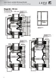
Lara classic variable Dichtung<br />
Ausführung der Tragkonstruktion<br />
Es wird empfohlen, die Unterkonstruktion aus<br />
Brettschichthölzern herzustellen, da Vollholz-Konstruktionen<br />
dazu neigen, sich zu verwinden.<br />
Die Dimensionierung ist den statischen Erfordernissen<br />
anzupassen.<br />
Montage der inneren Dichtungen<br />
Auf durchlaufenden Pfosten oder Sparren wird die innere<br />
Dichtung PD 60-100 verwendet. Die quer dazu<br />
anstoßenden Riegel oder Wechsel werden mit der Dichtung<br />
RD 60-100 ausgeführt. Die Dichtungen sind selbstklebend<br />
ausgerüstet und werden einfach auf das Tragwerk geklebt.<br />
Um die Dichtung exakt parallel montieren zu können, ist die<br />
Ausbildung von Fälzen am Tragwerk empfehlenswert. Zur<br />
weiteren Fixierung können Stahlstifte verwendet werden, die<br />
unter den Spreizlippen genagelt werden.<br />
Im Bereich der Holzbreiten über 60 bis 100 mm werden die<br />
Dichtungen an den Soll-Trennstellen aufgerissen und<br />
überdecken somit variabel die unterschiedlichen<br />
Holzbreiten.<br />
Herstellung der Dichtungsüberlappung<br />
Am T-Stoß wird mit scharfem Messer durch Anbringen von<br />
rückseitigen Klinkungen [Ku] an der Riegel-Dichtung (RD<br />
60-100) und vorderseitigen Aussparungen [Ko] an der<br />
Pfosten-Dichtung (PD 60-100) eine Überlappung hergestellt.<br />
An den Kontaktstellen und letzten Öffnungen wird die<br />
Überlappung mit EPDM-Dichtmasse [AD]<br />
abgedichtet.<br />
Glasauflagen<br />
Bei senkrechten Verglasungen müssen unter jeder Scheibe<br />
je 2 Stck. Glasauflagen ca. 100 mm vom Eck montiert<br />
werden. Hierzu sind die System-Schrauben (PD-RD) mit<br />
abgezogenem Dichtring (2 Stck/Auflage) mit den<br />
Glasauflagen GAE 22 oder GAE 28 zu verwenden. Es<br />
können somit Glasgewichte bis 50 kg aufgenommen<br />
werden. Bei Glasgewichten bis max. 75 kg wird eine<br />
zusätzliche Schraube mittig unter die Glasauflage gesetzt.<br />
Auswahl Glasauflagen<br />
Glasdicke Ausführung<br />
Glasauflage<br />
6 <strong>–</strong> 8 mm Glasauflage direkt auf den Schraubenkopf<br />
9 <strong>–</strong> 22 mm GAE 22, in Eigenfertigung beschnitten<br />
24 <strong>–</strong> 27 mm GAE 22<br />
28 <strong>–</strong> 33 mm GAE 28<br />
Auswahl der Grund- und Abdeckprofile<br />
Die Ansichts-Breiten der Grund- und Abdeckprofile können<br />
je nach Breite der Holzunterkonstruktion zwischen 50, 55,<br />
60, 64, 80 und 100 mm gewählt werden.<br />
Zuschnitt und Vorbereitung der Grundprofile<br />
Die Pfosten-Grundprofile werden auf die erforderliche Länge<br />
geschnitten. Die dazwischenliegenden Riegel-Grundprofile<br />
werden beidseitig um je 3 mm kürzer als die Pfosten-<br />
Abdeckprofil-Lichte hergerichtet. Grundsätzlich muss evt.<br />
durch eine zusätzliche Bohrung ∅ 6 mm sichergestellt sein,<br />
dass der Abstand der Befestigungsbohrungen nicht größer<br />
als 60 mm vom Rand ist.<br />
LARA<br />
Glasdicke<br />
Montage der Grundprofile<br />
Nach dem Einsetzen der Verglasung werden die<br />
Grundprofile montiert. Hierzu werden in die Grundprofile die<br />
jeweils vorgesehene Verglasungsdichtung eingezogen. Für<br />
die Verschraubung steht die Systemschraube “PD-RD“ zur<br />
Verfügung. Die Schraube wird mittig in den vorgestanzten<br />
Löchern platziert und durch die inneren<br />
Verglasungsdichtungen direkt im Holz verschraubt. Bei der<br />
Verschraubung muss auf gleichmäßigen Anpressdruck<br />
geachtet werden: Die Innendichtung muss mit genügendem<br />
Anpressdruck am Glas anliegen, die äußere<br />
Verglasungsdichtung muss gleichmäßig und ohne<br />
Verwerfung an den Schraubpunkten durchlaufen.<br />
Montage der Abdeckprofile<br />
Das Pfosten-Abdeckprofil wird auf die erforderliche Länge<br />
geschnitten und auf das Grundprofil aufgeklipst. Für einige<br />
Abdeckprofile stehen Endkappen zur Verfügung, die am<br />
Sparrenende eingeschoben und verklebt werden können.<br />
Ausführbare Dachneigungen<br />
Die minimale Neigung des Glasdaches sollte 10° nicht<br />
unterschreiten.<br />
Glasfalz-Entlüftung<br />
Der Glasfalz wird durch das durchgängige Falz-System vom<br />
Riegel in den Pfosten belüftet. Die Pfosten bzw. Sparren<br />
sind an der Unterkante so auszuführen, dass evtl.<br />
auftretendes Kondensat im Glasfalz schadlos nach außen<br />
abgeführt werden kann.<br />
13
14<br />
Verarbeitungshinweise<br />
Statik<br />
Erforderliche Sparrenquerschnitte für Wintergartenkonstruktionen<br />
(gem. neuer DIN 1055, in Deutschland baurechtlich gültig ab Jan. 2007)<br />
LARA<br />
Die Tabellen sind nur für eine statische Vorbemessung geeignet, Sie ersetzen in keinen Fall eine statische Berechnung durch<br />
einen Statiker.<br />
Voraussetzung für die Anwendung der Tabellen:<br />
• Die Lastannahme und Anwendungsbereich werden vom Anwender geprüft, eingehalten oder in ihren Betrag unterschritten.<br />
• Der Wintergarten wird als geschlossenes Bauwerk betrachtet, da bei offenen Konstruktionen evtl. größere Windlasten zu<br />
erwarten sind.<br />
• Höhenversprünge und Aufbauten, bei denen es zu Anwehungen und Abrutschen von Schnee eines höher liegenden<br />
Daches kommt, müssen gesondert berücksichtigt werden. Die maximale Firsthöhe beträgt 6 m ab Geländeniveau.<br />
• Die Dachkonstruktion darf nur für Reinigungszwecke ausnahmsweise betreten werden.<br />
• Den Tabellen liegen folgende Werte zugrunde:<br />
Maximale Durchbiegung: kleiner l/300 bzw. max. 8 mm<br />
Glasgewicht: 35 kg/m² entsprechend 14 mm Gesamtglasdicke<br />
Dachneigung: 15° bis 30°<br />
Holzqualität: GL 24 (E-Modul = 11600 N/mm²)<br />
Schneelast “si“ auf dem Dach: si = sk x 0.8 (Angabe in Schneelastnorm = ‘‘sk“)<br />
Die Schneelast “sk“ kann ergänzend im zust. Bauamt erfragt werden<br />
Windlast q = 0.65 kN/m²<br />
= Windzone 1,2<br />
(Einbau unter 10 m)<br />
Sparrenhöhe<br />
Tabelle 1: “erforderliche Sparrenhöhe bei Schneelast si = 0.75 kN/m², sk = 0.9375 kN/m²“<br />
Geltungsbereich in: Zone 1 bis 550 m über NN, Zone 1a bis 450 m über NN. Zone 2 bis 310 m über NN<br />
Sparren-<br />
Raster<br />
Sparren-<br />
Breite<br />
Erforderliche Sparrenhöhe (mm) bei Schneelast si = 0.75 kN/m² bei<br />
Sparrenlänge (cm):<br />
150 cm 200 cm 250 cm 300 cm 350 cm 400 cm 450 cm 500 cm<br />
60 cm 60 mm 60 mm 80 mm 100 mm 120 mm 150 mm 180 mm 210 mm 240 mm<br />
80 mm 60 mm 70 mm 90 mm 110 mm 140 mm 160 mm 190 mm 220 mm<br />
100 mm 50 mm 70 mm 80 mm 110 mm 130 mm 150 mm 180 mm 200 mm<br />
80 cm 60 mm 70 mm 90 mm 110 mm 140 mm 170 mm 200 mm 130 mm 260 mm<br />
80 mm 60 mm 80 mm 100 mm 120 mm 150 mm 180 mm 210 mm 240 mm<br />
100 mm 60 mm 70 mm 90 mm 120 mm 140 mm 170 mm 200 mm 220 mm<br />
100 cm 60 mm 70 mm 90 mm 120 mm 150 mm 180 mm 210 mm 250 mm 280 mm<br />
80 mm 70 mm 90 mm 110 mm 130 mm 160 mm 190 mm 230 mm 260 mm<br />
100 mm 60 mm 80 mm 100 mm 120 mm 150 mm 180 mm 210 mm 240 mm<br />
Tabelle 2: “erforderliche Sparrenhöhe bei Schneelast si = 1.25 kN/m², sk = 1.56 kN/m²“<br />
Geltungsbereich in: Zone 1 bis 795 m über NN, Zone 1a bis 680 m über NN, Zone 2 bis 490 m über NN<br />
Zone 2a bis 405 m über NN, Zone 3 bis 360 m über NN<br />
Sparren-<br />
Raster<br />
Sparren-<br />
Breite<br />
Sparrenlänge<br />
Sparrenraster<br />
Erforderliche Sparrenhöhe (mm) bei Schneelast si = 1.25 kN/m² bei<br />
Sparrenlänge (cm):<br />
150 cm 200 cm 250 cm 300 cm 350 cm 400 cm 450 cm 500 cm<br />
60 cm 60 mm 70 mm 90 mm 110 mm 140 mm 170 mm 200 mm 230 mm 270 mm<br />
80 mm 60 mm 80 mm 100 mm 130 mm 150 mm 180 mm 210 mm 240 mm<br />
100 mm 60 mm 70 mm 90 mm 120 mm 140 mm 170 mm 200 mm 230 mm<br />
80 cm 60 mm 70 mm 100 mm 120 mm 150 mm 180 mm 220 mm 250 mm 290 mm<br />
80 mm 70 mm 90 mm 110 mm 140 mm 170 mm 200 mm 230 mm 270 mm<br />
100 mm 60 mm 80 mm 100 mm 130 mm 160 mm 190 mm 220 mm 250 mm<br />
100 cm 60 mm 80 mm 100 mm 130 mm 160 mm 200 mm 240 mm 270 mm 310 mm<br />
80 mm 70 mm 90 mm 120 mm 150 mm 180 mm 210 mm 250 mm 290 mm<br />
100 mm 70 mm 90 mm 110 mm 140 mm 170 mm 200 mm 230 mm 270 mm<br />
Sparren-<br />
Breite
Verarbeitungshinweise<br />
Statik<br />
LARA<br />
Schneelastzonen Bundesrepublik Deutschland gemäß DIN 1055, Teil 5, 2005-07<br />
(baurechtlich gültig ab Jan. 2007)<br />
15
16<br />
Verarbeitungshinweise<br />
Twinloc<br />
Twinloc-Verbinder für Senkrecht-Fassaden<br />
<strong>Gutmann</strong> Twinloc verbindet Pfosten- und Riegel-<br />
Holzkonstruktionen mit Holzansichtsbreite von 50<strong>–</strong>80 mm. Zur<br />
Überprüfung der Tragfähigkeit und für den statischen Nachweis<br />
ist die Technische Info „Statische Werte“ oder die allgemeine<br />
bauaufsichtliche Zulassung zu Grunde zu legen.<br />
Pfostenmontage Riegelmontage<br />
Verbindung Twinloc-Verbinder<br />
Twinloc: Verbinder-Auswahl für Senkrecht<strong>–</strong>Fassaden<br />
Verbinder Riegeltiefe max. Glasgewicht (2)<br />
-Typ von-bis (1)<br />
(mm)<br />
Standard Schwerlast<br />
TL 41 59-76 170 kg 170 kg<br />
TL 59 77-94 226 kg 226 kg<br />
TL 77 95-112 234 kg 234 kg<br />
TL 95 113-148 250 kg 250 kg<br />
TL 131 149-189 316 kg 326 kg<br />
(1) Größere Riegeltiefen werden durch Kopplung der Verbinder erreicht.<br />
Die dadurch möglichen höheren Belastungen bleiben in den<br />
dargestellten maximalen Beanspruchungen unberücksichtigt.<br />
(2) Die maximalen Glaslasten sind angegeben als max. Tragfähigkeit<br />
eines durchlaufenden Riegels mit 2 gleichen Verbindern ausgedrückt als<br />
Gesamt-Glasgewicht. Weitere Möglichkeiten die Tragfähigkeit zu<br />
erhöhen sind der „Technischen Information: Statische Werte“ zu<br />
entnehmen.<br />
Stirnseitige Fräsung am Riegel<br />
Mit handelsüblicher Handoberfräse (Fräser Ø 14 mm, Anlaufring<br />
Ø 24 mm) und der Twinloc-Schablone wird eine Aussparung mit<br />
12 - 12,5 mm Tiefe am Riegel (am anstoßenden Teil) gefräst.<br />
Schablone unten Schablone oben<br />
Schablone<br />
stirnseitige Riegelfräsung<br />
Tiefe 12-12,5 mm<br />
Riegeltiefe<br />
LARA<br />
Bohren der Pfosten<br />
Die Verschraubung der Pfosten wird zur exakten<br />
Positionierung der Verschraubung mit Ø 3 mm durch die<br />
Bohrbuchsen der Schablone vorgebohrt. Die Achse des<br />
Riegels wird an der Fräsausparungskante der Schablone<br />
angelegt. Die Tiefenposition der Verschraubung wird mit dem<br />
Winkelanschlag so eingestellt, dass die Vorderkante des<br />
Verbinder 6 mm hinter der Vorderkante Holzkonstruktion<br />
liegen.<br />
Pfosten<br />
außen =<br />
= Position<br />
Winkel-<br />
Anschlag<br />
Verschraubung der Verbinder<br />
Grundsätzlich werden die Schrauben der Länge 5/80 zur<br />
Befestigung in das Längsholz, die Schrauben 5/50 zur<br />
Befestigung in das Querholz benutzt. Bei harten Hölzern, bzw.<br />
bei Einsatz nahe der Holzkante sollte mit Ø 3 mm vorgebohrt<br />
werden. Bei der Schwerlast-Verschraubung werden alle<br />
Bohrungen der Verbinder genutzt. Bei der Standard-<br />
Verschraubung wird die Verschraubung gemäß Skizze<br />
ausgeführt.<br />
Skizze: Standard-Verschraubung<br />
TL 41: 4 Stck Schr. TL 59: 6 Stck Schr. TL 77: 6 Stck Schr.<br />
TL 95: 6 Stck Schrauben TL 131: 8 Stck Schrauben<br />
Schraubgruppe mit 4 Stck Schrauben immer an Glaslastseite<br />
(= Holzaussenseite)<br />
Zusammenbau der Holzverbindung<br />
Der Riegel kann entweder von innen nach aussen<br />
eingeschoben, oder, wie in der Skizze dargestellt, von der<br />
Seite her eingehängt werden.<br />
Skizze: Montage<br />
durch seitliches Einhängen<br />
Durch Einschrauben der<br />
gefetteten Verbindungsschraube<br />
in den Schraubkanal<br />
(Akkuschrauber mit<br />
Torx-Bit T25), der aus beiden<br />
Verbinderteilen gebildet wird,<br />
entsteht eine bei Bedarf<br />
lösbare Verspannung des<br />
Verbinders in allen drei<br />
Dimensionen. Der Riegel<br />
wird hierdurch auf der<br />
ganzen Tiefe gleichmäßig<br />
fest an den Pfosten gepresst.<br />
4<br />
Achse Riegel = Kante<br />
Aussparung<br />
Skizze: gekoppelter<br />
Verbinder<br />
Schablone<br />
Bei großen Riegeltiefen ab<br />
190 mm werden innenseitig<br />
am Verbinder TL 131 die<br />
erforderlichen Verbinder (mit<br />
Standard-Verschraubung)<br />
gekoppelt. Der auf Länge<br />
des gekoppelten Verbinders<br />
angepasste Stift VTL 135<br />
wird ca. 2 cm versenkt eingeschlagen<br />
und von der<br />
Verbindungsschraube in die<br />
endgültige Position geschoben.
Verarbeitungshinweise<br />
Twinloc<br />
Twinloc Verbinder für Holzdach-Konstruktion<br />
<strong>Gutmann</strong> Twinloc kann auch für Holzdach-Konstruktion<br />
verwendet werden: Twinloc verbindet Sparren und Pfetten<br />
mit Holzansichtsbreite von 50<strong>–</strong>80 mm. Zur Überprüfung der<br />
Tragfähigkeit und für den statischen Nachweis ist die<br />
Technische Info „Statische Werte“ oder die allgemeine<br />
bauaufsichtliche Zulassung zu Grunde zu legen.<br />
Ansicht Fräsung in Pfette<br />
Ausführung der Fräsung<br />
Mit handelsüblicher Handoberfräse ( Fräser Ø 14 mm,<br />
Anlaufring Ø 24 mm) und der Twinloc-Schablone wird eine<br />
Aussparung mit 12 - 12,5 mm Tiefe gefräst. Winkel- und<br />
Flachanschläge können auf der Grundplatte hierzu beliebig<br />
getauscht werden. In der Regel wird die Aussparung an der<br />
Pfette (am durchlaufenden Teil) hergestellt<br />
Bohren der Sparren<br />
Zur exakten Positionierung der Verbinder am Sparrenende<br />
werden die Positionen der Schrauben mit der Schablone mit<br />
ø 3 mm vorgebohrt<br />
LARA<br />
Twinloc: Verbinder-Auswahl für Holzdach- Konstruktionen<br />
Verbinder Minimale Belastbarkeit FQ (2)<br />
-Typ Sparrenhöhe<br />
bei<br />
20º Dachneigung<br />
ca.: (1)<br />
Standard Schwerlast<br />
TL 41 80 mm 342 kg 342 kg<br />
TL 59 100 mm 514 kg 514 kg<br />
TL 77 120 mm 514 kg 686 kg<br />
TL 95 135 mm 514 kg 858 kg<br />
TL 131 170 mm 686 kg 1202 kg<br />
(1) Größere Sparrenhöhen können durch Kopplung der Verbinder<br />
(siehe Angaben zur Senkrecht-Fassade) erreicht werden. Der<br />
Sparren ist abhängig von der Belastung separat zu dimensionieren.<br />
(2) Die maximalen Belastbarkeit Fq ist angegeben als max.<br />
Tragfähigkeit eines Sparrens mit zwei gleichen Verbindern für die<br />
Lastrichtung längs zur Achse des Verbinders bei Holzrohdichten.<br />
>= 430 kg/m³<br />
Ansicht Verbinder<br />
in Pfette und Sparren Seitenansicht<br />
ATL-38<br />
Verschraubung der Verbinder<br />
Bei der Verschraubung der Verbinder als Standard oder<br />
Schwerlast<strong>–</strong>Verschraubungen wird verfahren, wie bei der<br />
Senkrecht<strong>–</strong>Fassade beschrieben.<br />
Zusammenbau der Holzverbindung<br />
Nach Befestigung der Auflage ALT-38 wird der Sparren<br />
(Wechsel) von oben eingeschoben oder von der Seite her<br />
eingehängt und mit der gefetteten Verbindungsschraube<br />
verschraubt. Hierdurch entsteht eine hochbelastbare<br />
Verbindung, die bei Bedarf auch wieder lösbar ist.<br />
17
18<br />
Verarbeitungshinweise<br />
Twinloc<br />
Ermittlung der erforderlichen Twinloc<strong>–</strong>Verbinder beim Einsatz in Holzdachkonstruktionen<br />
(gemäß neuer DIN 1055, in Deutschland baurechtlich gültig ab Jan. 2007)<br />
LARA<br />
Die Tabelle sind nur für eine statische Vorbemessung geeignet. Sie ersetzen in keinem Fall eine statische Berechnung durch<br />
einen Statiker.<br />
Voraussetzung für Anwendung der Tabellen:<br />
• Der Einbau der Verbinder erfolgt gemäß Herstellervorgaben und der Zulassung.<br />
• Bei der Verschraubung wird zwischen Standard- und Schwerlast-Verschraubung (S-TL) unterschieden.<br />
• Die Lastannahmen und Anwendungsbereiche werden vom Anwender geprüft, eingehalten oder in ihrem Betrag<br />
unterschritten.<br />
• Der Wintergarten wird als geschlossenes Bauwerk betrachtet, da bei offenen Konstruktionen evtl. größere Windlasten zu<br />
erwarten sind.<br />
• Höhenversprünge und Aufbauten, bei denen es zu Anwehungen und Abrutschen von Schnee eines höher liegenden<br />
Daches kommt, müssen gesondert berücksichtigt werden. Die maximale Firsthöhe beträgt 6 m ab Geländeniveau.<br />
• Die Dachkonstruktion darf nur für Reinigungszwecke ausnahmsweise betreten werden.<br />
• Den Tabellen liegen folgende Werte zugrunde:<br />
Maximale Belastbarkeit: entsprechend der zugrunde liegenden Twinloc-Zulassung Nr. 9.1-682<br />
Glasgewicht: 35 kg/m² entsprechen 14 mm Gesamtglasdicke<br />
Dachneigung: 15° bis 30°<br />
Holzqualität: GL 24 (E-Modul = 11600 N/mm²)<br />
Schneelast “si” auf dem Dach: si = sk x 0.8 (Angaben in Schneelastnorm = “sk”)<br />
Die Schneelast “sk’” kann ergänzend im zust. Bauamt erfragt werden<br />
Windlast: q = 0.65 kN/m² = Windzone 1,2 (Einbau unter 10 m)<br />
• Die minimale Sparrenbreite beträgt 50 mm<br />
• Aus konstruktiver Sicht ist die Verbinderlänge zusätzlich mit der Sparrenhöhe abzustimmen. Dies wird oft zu<br />
abweichenden Lösungen führen, da die Tabellen nur den kleinsten zulässigen Verbinder angeben.<br />
Tabelle 1: “Auswahl Twinloc-Verbinder bei Schneelast si = 0.75 kN/m², sk = 0.9375 kN/m² “<br />
Geltungsbereich in: Zone 1 bis 550 m über NN, Zone 1a bis 450 m über NN, Zone 2 bis 310 m über NN<br />
“S-TL” = Schwerlastverschraubung, “TL” = Standard-Verschraubung<br />
Sparren-<br />
Raster “R”<br />
Sparrenlänge “L“<br />
Sparrenraster“R“<br />
Kleinter Verbinder bei Schneelast si = 0.75 kN7m²<br />
bei Sparrenlänge “L” (cm):<br />
150 cm 200 cm 250 cm 300 cm 350 cm 400 cm 450 cm 500 cm<br />
60 cm TL 41 TL 41 TL 41 TL 41 TL 41 TL 59 TL 59 TL 59<br />
80 cm TL 41 TL 41 TL 41 TL 59 TL 59 TL 59 TL131<br />
S-TL 77<br />
100 cm TL 41 TL 41 TL 59 TL 59 TL 131 TL 131 S-TL 95<br />
S-TL 77 S-TL 77 S-TL 131<br />
TL 131<br />
S-TL 77<br />
S-TL 95<br />
S-TL 131<br />
Tabelle 2: “Auswahl Twinloc-Verbinder bei Schneelast si = 1.25 kN/m², sk = 1.56 kN/m²”<br />
Geltungsbereich in: Zone 1 bis 795 m über NN, Zone 1a bis 680 m über NN, Zone 2 bis 490 m<br />
Zone 2a bis 405 m über NN, Zone 360 m über NN<br />
“S-TL” = Schwerlastverschraubung, “TL” = Standard <strong>–</strong> Verschraubung<br />
Sparrenhöhe<br />
über NN,<br />
Sparren- Kleinster Verbinder bei Schneelast si = 1.25 kN/m²<br />
Raster “R” bei Sparrenlänge “L” (cm):<br />
150 cm 200 cm 250 cm 300 cm 350 cm 400 cm 450 cm 500 cm<br />
50-80mm<br />
60 cm TL 41 TL 41 TL 41 TL 59 TL 59 TL 59 TL 131 TL 131<br />
S-TL 77 S-TL 77<br />
80 cm TL 41 TL 41 TL 59 TL 59 TL 131 TL 131 S-TL 95 S-TL 95<br />
S-TL 77 S-TL 77 S-TL 131 S-TL 131<br />
100 cm TL 41 TL 59 TL 131 TL 131 S-TL 95 S-TL 95 S-TL 131 S-TL 131<br />
S-TL 77 S-TL 77 S-TL 131 S-TL 131
Processing guidelines<br />
Lara GF<br />
General:<br />
The following processing guidelines will explain how to<br />
proceed when manufacturing and mounting mullion-transom<br />
curtain walls, winter gardens, and glass walls in woodaluminum<br />
constructions. This information is based on our<br />
current level of experience. Building must follow all relevant<br />
standards and guidelines, common laws of engineering as<br />
well as the processing guidelines listed below. We do not<br />
assume liability for damages occurring as a result of<br />
improper processing. These guidelines do not include<br />
solutions for all object-specific exceptions. For further<br />
questions, please contact our technical application<br />
consultants.<br />
Construction of the supporting structure<br />
The structure is to be created as a wooden element from<br />
laminated lumber BS 11 / GL 24 in accordance with DIN<br />
1052 or from approved plywood. As an alternative, the<br />
structure may consist of steel or aluminum profiles. The<br />
dimensions must be adapted to the static requirements. It is<br />
also important that the structure is made to be even with the<br />
screw-on surface of the basic profile. For Preliminary static<br />
computations of a rafter a table is available below.<br />
Connections in the wooden load-bearing structure<br />
The connections between mullions and transoms (or rafters<br />
and purlins) must be able to absorb glass loads, wind loads,<br />
and snow loads without deforming or distorting the structure,<br />
which is achieved by Building Inspectorate approved<br />
<strong>Gutmann</strong> Twinloc connectors. For the right choice of<br />
connectors see the twinloc table below.<br />
Protection of the wood structure<br />
As a dimensionally stable component, the wood structure<br />
must receive appropriate surface protection in order to<br />
prevent dimension changes due to moisture expansion and<br />
surface damage due to dampness.<br />
In rooms that are likely to be humid, we recommend milling<br />
a center groove [1] (10 x 10 mm) on the exterior of the<br />
wood structure in order to release the moisture.<br />
Attaching basic profiles<br />
The basic profiles are screwed onto the wood structure with<br />
system stainless steel wood screws [2] 4 x 45 (use approx.<br />
7 screws per meter). Five screws each must be correctly<br />
placed around the glass contact points [3] (left and right<br />
below each glass pane). The basic profile is predrilled for<br />
screwing with Ø 5 mm bores every 150 mm.<br />
Milling grooves [4] is recommended to aid screwing and<br />
exact positioning of the profile on the center line of the wood<br />
structure.<br />
The transom basic profiles are cut into the intermediate<br />
space of the mullion basic profiles with 7 mm distance [5]<br />
on each side on the T-joint of the basic profile, so that the<br />
gasket on the mullion is not interrupted. Using the Twinloc<br />
connector distance 5 increases up to 19 mm. The end of<br />
the mullion basic profiles may be shortened [6] so that they<br />
are in line with the centerline of the transom basic profile in<br />
order to avoid heat loss at the mullion basic profile.<br />
When using the gaskets GF 50 (60) RF-E4 (for transom<br />
drainage), the transom basic profile goes straight through<br />
and the mullion basic profile abuts from the top with 7 mm<br />
distance [5].<br />
(19)<br />
LARA<br />
Attaching basic profiles on steel<br />
If the basic profiles are mounted onto (galvanized) steel<br />
strapping, plastic insulating tape and stainless steel screws<br />
M5, EN ISO 7045 must be used in order to prevent contact<br />
corrosion. In this case, punched oblong holes 5.5 x 30 mm<br />
must be used for mounting.<br />
Sealing and insulating component edges<br />
In order to achieve a high level of air tightness (for example<br />
for Blower Door tests) at the component edges (base point,<br />
verge, eaves, wall connections, etc.), sealing [7] with<br />
compression tapes or silicone must be allowed for between<br />
the basic profile and the wood construction. The basic profile<br />
must still display sufficient thermal insulation [8] to the<br />
exterior there once it is installed.<br />
(19)<br />
4.0 x 45<br />
Art. Nr. 800190<br />
19
20<br />
Processing guidelines<br />
Lara GF<br />
General information about mounting inner gaskets<br />
It is generally recommended to mount the gasket onto the<br />
prepared components while still in the factory to facilitate<br />
handling later. The gaskets are pressed into the reception<br />
grooves of the basic profile by hand or with a rolling tool (set<br />
to the respective gasket width). Due to possible color rub-off,<br />
it is recommended to wear gloves and avoid contact with the<br />
wood surface.<br />
Sealing system<br />
The standard mullion is usually constructed in level 3 [E3],<br />
while the standard transom is constructed in level 2 [E2]. If a<br />
curtain wall area needs to be divided again, the gasket on<br />
level 1 [E1] may be connected to the gasket on level 2 in an<br />
overlapping manner. If condensate from the glass rebate<br />
cannot be drained via the mullion rebate, a so called “transom<br />
drainage" may be created in the transom with the gasket on<br />
level 4 [E4]. The “Lara GF” system thus allows for 4 different<br />
gasket levels in the 50 mm and 60 mm construction widths<br />
and for 3 different gasket levels in the 80 mm construction<br />
width.<br />
standard<br />
construction<br />
Pressing in the gasket<br />
The continuous mullion (rafter) gaskets are placed on the basic<br />
profile directly “from the roll” and cut according to the length of<br />
the component.<br />
Notching of the continuous gasket [Kd]<br />
The glass contact lips of the continuous gasket are notched<br />
with a notching tool at the T-joints to fit the width of the<br />
abutting gasket and the remainder is torn off. To do this, the<br />
notching tool must be adjusted to the appropriate length and<br />
depth. The exact position of the recess is found by placing<br />
the guide of the notching tool on the basic profile and cutting<br />
the already mounted continuous gasket by applying pressure<br />
with the palm of a hand.<br />
Notching of the abutting gasket [Kd]<br />
The abutting gasket is prepared with approximately 1%<br />
allowance in length. When determining the length, please<br />
consider that the abutting gasket overlaps the continuous<br />
gasket by 13 mm. The back side of the abutting gasket of the<br />
T-joint is notched to the appropriate depth 13 mm from the<br />
end and the back area is torn off.<br />
Creating the gasket overlap<br />
The cleaned (for example with water and detergent) and dried<br />
overlap is closed with APTK sealant [AD] and the<br />
appropriate sealing part [DS] on the side of the abutting<br />
gasket. A streak of APTK sealant [AD] is placed in the recess<br />
of the continuous gasket and pressed together so that the<br />
glass contact lips are on one level.<br />
pressing in<br />
the gasket<br />
notching of the continuous gasket<br />
notching of the abutting gasket<br />
LARA<br />
sealing system
Processing guidelines<br />
Lara GF<br />
Glass thickness options<br />
Please see the table on the right for minimum and maximum<br />
glass thickness dimensions.<br />
The table is based on exterior glazing gaskets with a gap<br />
width of 4 mm. If gaskets for a gap width of 6 mm are used,<br />
the glass thickness must be 2 mm less.<br />
Preparing for the glass seat installation<br />
As described above, the basic profile must be attached at<br />
the glass seat with 5 screws. Please keep in mind the loadbearing<br />
capability of the mullion-transom connection as well<br />
as the deflection of the transom when exposed to the glass<br />
load.<br />
Glass seat installation and maximum glass<br />
weights<br />
According to the relevant glazing guidelines, exactly 2 glass<br />
seats are to be installed beneath each glass pane. The<br />
admissible glass loads for glass seats may be found in the<br />
table on the right. Depending on the glass thickness, the<br />
appropriate glass seats (see table) are screwed on with a<br />
distance of 90 - 100 mm from the mullion space using 2<br />
screws each of either B 5.5 x 22 (item no. 825522) or B 5.5<br />
x 38 (item no. 825538). For single glazing, the blocking is<br />
conducted directly on the screw channel of the basic profile.<br />
Function of the insulator<br />
The insulator has 2 functions:<br />
1.) Improving the thermal insulation value “Uf” and thus<br />
avoiding heat loss as well as reducing the formation of<br />
condensate.<br />
2.) Controlled ventilation and condensate drainage from the<br />
transom into the mullion glass rebate by dividing the<br />
adjacent fields.<br />
Choosing and installing the insulator<br />
The choice of insulator depends on the glass thickness and<br />
the basic profile to be used. (see table)<br />
The insulator is clipped onto the already installed gasket<br />
during the glazing process. Standard designed curtain walls<br />
with post drainage needs a space of 5-10 mm in between<br />
the butt joint of the insulators of transom and mulllion for<br />
drainage and ventilation.<br />
Due to its limited UV resistance, the insulator must be<br />
protected from sun exposure for at least two months<br />
after installation by applying the continuous glazing<br />
profiles.<br />
Maximum/minimum glass thickness<br />
glass<br />
thickness<br />
(mm)<br />
with basic profile<br />
P2011/50,<br />
P2011/60<br />
LARA<br />
with basic profile<br />
P2011/55,<br />
P2011/80<br />
other basic<br />
profiles and<br />
visibly<br />
screwed<br />
profiles<br />
6 <strong>–</strong> 8 -------------- available --------------<br />
9 <strong>–</strong> 12 available available --------------<br />
18 <strong>–</strong> 21 -------------- available --------------<br />
22 <strong>–</strong> 23 available available --------------<br />
24 <strong>–</strong> 44 available available available<br />
45 <strong>–</strong> 46 available available --------------<br />
47 <strong>–</strong> 48 available -------------- --------------<br />
Selection of glass seats / maximum glass load<br />
glass<br />
thickness<br />
(mm)<br />
type of glass contact point maximum<br />
glass load for<br />
6 <strong>–</strong> 12 direct contact of glass and basic<br />
glass<br />
thickness up<br />
profile<br />
to (mm)<br />
18 <strong>–</strong> 23 GA 26, cut on site up to 28 mm:<br />
24 <strong>–</strong> 28 GA 26 400 kg<br />
29 <strong>–</strong> 31 GA 34, cut on site up to 34 mm:<br />
32 <strong>–</strong> 36 GA 34 350 kg<br />
36 <strong>–</strong> 42 GA 44, cut on site up to 44 mm:<br />
42 <strong>–</strong> 46 GA 44 250 kg<br />
47 <strong>–</strong> 48 GA 44, recommendation:<br />
up to 48 mm:<br />
use glazing block with steel core 225 kg<br />
glass thickness 6 <strong>–</strong> 12 mm e.g. glass thickness 24 <strong>–</strong> 28 mm e.g. glass thickness 29 - 31 mm e.g. glass thickness 42 <strong>–</strong> 46 mm<br />
Selection of insulators<br />
glass with basic profile<br />
thickness<br />
(mm)<br />
P 2011/50, -/60 (*1) P 2011/55 P 2011/80<br />
24 <strong>–</strong> 28 IP 1 IP 2 IP 80, (*2)<br />
29 <strong>–</strong> 33 IP 2 IP 3 IP 80, (*2)<br />
34 <strong>–</strong> 38 IP 3 IP 4 IP 80, (*2)<br />
39 <strong>–</strong> 43 IP 4 IP 5 IP 80, (*2)<br />
44 <strong>–</strong> 48 IP 5 -------------- IP 80<br />
(*1) including similar visibly screwed profiles<br />
(*2) cut on site<br />
glass<br />
thickness<br />
basic profile<br />
insulator<br />
21
22<br />
Processing guidelines<br />
Lara GF<br />
Cutting and preparing the pressure profile or<br />
pressure strip<br />
The mullion pressure profiles are cut to the length needed.<br />
The transom pressure profiles in between are made 3 mm<br />
shorter than the cover profile space on each side. When<br />
using the pressure profiles P 2011/50 or P2011/60 with<br />
pressure strip sealing parts, the pressure profile is<br />
shortened on both sides of the transom by 8 mm each up to<br />
the mullion cover profile space. An additional bore of ∅ 6<br />
must always be placed to make sure that the distance<br />
between the fixation points is not longer than 60 mm from<br />
the edge.<br />
Sliding in the glazing gasket<br />
The glazing gasket must have<br />
approx. 1 % excess, be<br />
compressed and slid into the<br />
pressure profile. Since the<br />
pressure strip sealing part is used<br />
on the transom, the joint of the<br />
sealing part must be glued to the<br />
end of the glazing gaskets with<br />
EPDM adhesive. When mounting<br />
without a sealing part, the gasket<br />
on the transom pressure profile<br />
must project 3 to 5 mm on each<br />
side in order to create a closed<br />
joint with the continuous mullion<br />
gasket, which should be glued<br />
with EPDM sealant, once the<br />
installation is complete.<br />
Bonding<br />
Pressure strip<br />
Sealing part<br />
Using special glazing gaskets<br />
If transom cover profiles sloped towards the glass (P<br />
2016/13-55 to -100) are installed, the transom gasket<br />
7500043 must be used.<br />
For glass joints (trimming) with silicone joint tape, it is<br />
recommended to use the silicone gasket 7500042. The<br />
joints of joint tape and gasket may be made durable with<br />
silicone adhesive.<br />
Preparing installation of the pressure profiles<br />
The choice of screws depends on the glass thickness and<br />
the pressure profile (see table) to be used.<br />
The pressure profiles are installed after the glass panes<br />
have been professionally blocked, secured with "short<br />
pieces"<br />
(= approx. 15 cm sections from pressure profiles with<br />
inserted gasket, installed in line with the glass pane), and<br />
inserted.<br />
Installing the pressure profiles<br />
The pressure profiles are usually screwed in with a torque of<br />
4.0 Nm. Even contact pressure is important for the screwing<br />
process: The inner gasket must be touching the glass with<br />
sufficient contact pressure, the outer glazing gasket must be<br />
even and continuous without distortions at the screw points.<br />
A simple, easy to make template may help determine the<br />
distance to be kept from the outer edge of the pressure<br />
profile to the glass level.<br />
LARA<br />
Selection of screws<br />
(when using glazing gaskets with a gap width of 4 mm) for<br />
pressure profiles P 2011/55 and P 2011/80 N:<br />
glass<br />
thickness<br />
item no.<br />
477530<br />
screw<br />
length<br />
screw “L"<br />
6 - 7 mm 815525 25 mm<br />
8 - 12 mm 815530 30 mm<br />
18 - 20 mm 815538 38 mm<br />
21 - 22 mm 815540 40 mm<br />
23 - 24 mm 815542 42 mm<br />
25 - 27 mm 815545 45 mm<br />
28 - 31 mm 815548 48 mm<br />
32 - 33 mm 815550 50 mm<br />
34 - 35 mm 815552 52 mm<br />
36 - 38 mm 815555 55 mm<br />
39 - 40 mm 815558 58 mm<br />
41 - 42 mm 815560 60 mm<br />
43 - 44 mm 815562 62 mm<br />
45 - 46 mm 815565 65 mm<br />
for pressure profiles P 2011/50, P 2011/60, P HGF-50:<br />
glass<br />
thickness<br />
item no.<br />
477530<br />
screw<br />
length<br />
screw “L"<br />
9 - 11 mm 815525 25 mm<br />
12 - 16 mm 815530 30 mm<br />
22 - 24 mm 815538 38 mm<br />
25 - 26 mm 815540 40 mm<br />
27 - 28 mm 815542 42 mm<br />
29 - 31 mm 815545 45 mm<br />
32 - 34 mm 815548 48 mm<br />
35 - 36 mm 815550 50 mm<br />
37 - 38 mm 815552 52 mm<br />
39 - 40 mm 815555 55 mm<br />
41 - 42 mm 815558 58 mm<br />
43 - 44 mm 815560 60 mm<br />
46 - 47 mm 815562 62 mm<br />
48 - 50 mm 815565 65 mm<br />
for visibly screwed cover profiles,<br />
such as P 2020/50-11:<br />
glass item no. length<br />
thickness 477530<br />
screw<br />
screw “L"<br />
24 - 25 mm 816540 40 mm<br />
26 - 27 mm 816542 42 mm<br />
28 - 30 mm 816545 45 mm<br />
31 - 33 mm 816548 48 mm<br />
34 - 35 mm 816550 50 mm<br />
36 - 37 mm 816552 52 mm<br />
38 - 40 mm 816555 55 mm<br />
41 - 43 mm 816558 58 mm<br />
44 mm 816560 60 mm<br />
Cutting and preparing the cover profiles<br />
(= cover plates)<br />
First, the mullion cover profile is clipped on and, if<br />
necessary, kept from slipping by means of a lateral screw. If<br />
no sealing part is used at the transom, the 3 mm gap<br />
between transom pressure profile and mullion cover profile<br />
should be sealed with silicone.<br />
The transom cover profile is cut with a 0.5 to 1 mm gap in<br />
the space of the mullion cover profile and then clipped on.<br />
For some cover profiles, end covers are available, which<br />
may be inserted at the end of the rafter to cover up the<br />
visible opening of the profiles. The end covers are glued in<br />
with silicone and secured with screws or rivets. Should<br />
disassembly of the cover profiles become necessary, we<br />
recommend the use of finishing tools in order to avoid<br />
damage to the profiles.
Processing guidelines<br />
Lara GF<br />
Construction with visibly screwed cover profiles<br />
The visibly screwed cover profiles are delivered in a nonpunched<br />
version. The bores must be drilled with a short step<br />
drill with a distance of max. 250 mm in between and max.<br />
60 mm from the profile end. Use screws with a big head (∅<br />
10 m). The glass joint is sealed continuously with a butyl<br />
strip under the cover profile. As an alternative, the joint of<br />
transom and mullion may be backed by cross joint plate<br />
KSB 42/50. This requires the lateral groove between<br />
transom cover profile and cross joint plate to be sealed in a<br />
permanently elastic manner.<br />
Installation using a butyl strip<br />
Before mounting the pressure profile, the glass joint may be<br />
completely taped over with the self-adhesive butyl strip and<br />
therefore sealed if necessary. Self-cleaning glass is not<br />
affected in its function by the butyl strip. The application of<br />
butyl strips is especially recommended for glazing roofs with<br />
a shallow incline, with complicated sectioning, or when<br />
using visibly screwed cover profiles. The fastening screws of<br />
the basic profiles, which pierce through the butyl strip, must<br />
be greased with commercial machine grease so that the<br />
butyl strip does not tear at the screw points. If insulators and<br />
butyl strips are used at the same time, the special<br />
installation circumstances must be considered when<br />
choosing the insulator.<br />
Glass rebate ventilation and drainage<br />
Mullion drainage<br />
The glazing system is constructed to feature “multiple field<br />
ventilation”. The glass rebate is ventilated through the<br />
transom on all 4 corners of the pane fields into the mullion<br />
glass rebate. The structure must be created in a way that<br />
allows the glass rebates of the mullions (or rafters) to be<br />
opened towards the outside for ventilation and for the safe<br />
drainage of possible condensate. (= structure type “mullion<br />
drainage”)<br />
Transom drainage<br />
If in rare cases the mullion cannot be opened towards the<br />
bottom, the gasket GF 50 (60) RF-E4 can perform the so<br />
called "transom drainage". For this to happen, the mullions<br />
are first drained into the lowest transom, which guides the<br />
moisture to the exterior via small recesses (approx. 5-8 cm<br />
every 80 cm) in the outer (lower) glazing gasket. The<br />
pressure profile of the continuous mullion is the shortened<br />
down to the center line of the transom in order to create<br />
LARA<br />
additional drainage openings at the base point of the mullion.<br />
The lateral ends of the glass rebate of the lowest transom<br />
are closed off with insulators and EPDM sealant so that<br />
moisture may only be released in a controlled manner<br />
through the planned openings.<br />
Please also see the appropriate detailed drawing in this<br />
catalog.<br />
Additional openings for ventilation<br />
If the curtain wall elements are placed higher than regular<br />
room-high window elements, the distances between the<br />
sections to be ventilated and the drainage opening at the<br />
end of the mullion may become too long. For transoms<br />
exceeding the distance to the drainage opening by 2.5 m,<br />
additional ventilation openings are recommended in the form<br />
of bores ∅ 6 mm on the bottom side of the profile, or<br />
recesses [Ub] in the outer (lower) glazing gasket (recess L<br />
= 30 mm). The openings must be placed on both sides of the<br />
transom, approximately 150 mm from the edge. For<br />
transoms longer than 1.5 m, additional notches (L = 30 mm)<br />
in the insulator are necessary and ventilation openings must<br />
be placed every 1000 mm. The ventilation openings must be<br />
continuous up to the glass rebate.<br />
Sloped glass structures<br />
Lara GF is suitable for the application as a glass roof system<br />
for slopes from 10º to 90º. For lateral profiles (trimmings) it is<br />
important to keep the structural height low so that water can<br />
drain freely.<br />
Self-purification of the glass is limited for flat roofs due to<br />
slowly draining water. Flat roofs are also subject to increased<br />
risk of water leakage. The slope of the glass roof may<br />
therefore never be lower than 10°.<br />
Glazing, which is only 10° from being vertical, is considered<br />
vertical glazing according to the German TRLV Guideline<br />
and therefore provides a wider range of glass for selection.<br />
CE certification for curtain walls<br />
Structures, which are up to 15° from being vertical, are<br />
considered curtain walls according to DIN EN 13830 and<br />
must therefore display a CE certification from the curtain wall<br />
manufacturer.<br />
<strong>Gutmann</strong> will provide extensive support in this endeavor.<br />
23
24<br />
Processing guidelines<br />
Lara classic<br />
Construction of the supporting structure<br />
The wood qualities, surface treatment and dimension<br />
information described for the “Lara GF” system, mostly<br />
apply to “Lara classic” as well.<br />
However, please also note the following for Lara classic:<br />
Glass rebate<br />
Millings or gluing and screwing wood borders prepare the<br />
wood construction for the reception of the inner gasket and<br />
the glass. It is important that the rebate dimensions are<br />
adapted to the thickness of the glass. The glass rebate of<br />
the continuous mullion (rafter) must be continuous at the Tjoint<br />
as well so that moisture can be released. Please check<br />
the base points of mullions and rafters to make sure that the<br />
moisture on the inner gasket level can easily be released to<br />
the outside.<br />
Glazing<br />
The glass panes are placed directly into the glass rebate<br />
and professionally blocked with 2 glazing blocks each on the<br />
bottom edge of the pane. Secure the panes with “short<br />
pieces” (= approx. 15 cm sections from basic profiles with<br />
inserted gasket, installed in line with the glass pane).<br />
The maximum glass weights for vertical glazing are based<br />
on the load bearing capacity of each wood construction and<br />
must be determined on-site. The table therefore only<br />
provides approximate values.<br />
Approximate values: maximum glass weight Lara classic<br />
glass<br />
thickness<br />
(mm)<br />
construction<br />
width<br />
64 mm<br />
construction<br />
width<br />
80 mm<br />
construction<br />
width<br />
100 mm<br />
up to 34 120 kg 200 kg 300 kg<br />
up to 44 80 kg 150 kg 250 kg<br />
LARA<br />
Mounting inner gaskets<br />
For vertical glazing, the inner silicone gasket 2020/2 or the<br />
APTK gaskets 2020/5 or 2030/5 may be used. For<br />
increased tightness requirements, the T-joints of silicone<br />
gaskets should be sealed with neutral silicone.<br />
Two-layer APTK gaskets (2020/5N or 2030/5N) must be<br />
used for high driving rain loads and glass roofs. With a<br />
sharp knife or broad broach, the continuous gaskets receive<br />
a notch on top [Ko] at the T-joint, while the abutting gasket<br />
receives a notch on the bottom [Ku]. The gasket joint is<br />
overlapped and sealed with EPDM sealant [AD] towards<br />
the wood and between the gaskets.<br />
Cutting and mounting pressure and cover profiles,<br />
inserting gaskets<br />
All information provided in the Processing Guidelines for the<br />
“Lara GF” system applies here as well.<br />
Installing the pressure profiles<br />
Unlike in the “Lara GF” system, the pressure profile in Lara<br />
classic is fixed directly in the wood through system fastener<br />
H 2000 with V2a Spax screws 5 x 50. The fastener is<br />
clipped into the punched oblong holes of the pressure<br />
profiles and positioned in the center of the oblong hole<br />
before screwing. The rebate projection on the fastener is<br />
used to position the pressure profiles on the center of the<br />
wood profile. It is important for screwing that the bracing<br />
projection on the fastener is pressed tightly onto the profile<br />
by the flat head of the screw, yet not sheared off, so that the<br />
profile can glide on the fastener and the profile still has<br />
enough room for heat expansion.
Processing guidelines<br />
Lara classic<br />
Sealing the T-joint<br />
The transom basic profile is made to be 3 mm shorter than<br />
the cover Sealing profile the space. T-jointDuring<br />
installation, the 3 mm gap<br />
between The transom basic profile is made and mullion to be 3 cover mm shorter profilethan<br />
must the be cover sealed profile with silicone. space. During installation, the 3 mm gap<br />
between transom basic profile and mullion cover profile<br />
Glass must rebate be sealed ventilation with silicone.<br />
The glass rebate is ventilated though the continuous rebate<br />
system Glass from rebate the transom ventilation into the mullion (= multiple field<br />
ventilation) The glass and rebate also is by ventilated rear-ventilation though between the continuous the front rebate<br />
edges system of wood from profile the transom and basic into profile. the mullion The structure (= multiple mustfield<br />
be created ventilation) in a and way also that by allows rear-ventilation the glass rebates between of the thefront<br />
mullions edges (or of rafters) wood profile to be and opened basic towards profile. the The outside structure formust<br />
ventilation be created and for in the a way safe that drainage allows of possible the glass condensate. rebates of the<br />
mullions (or rafters) to be opened towards the outside for<br />
Additional ventilation openings and for the for safe ventilation drainage of possible condensate.<br />
If the curtain wall elements are placed higher than regular<br />
room-high Additional window openings elements, for the ventilation distances between the<br />
fields If to the be curtain ventilated wall and elements the drainage are placed opening higher at than the end regular<br />
of the room-high mullion may window become elements, to long. the For transoms distances exceeding between the<br />
the distance fields to be to ventilated the drainage and opening the drainage by 1.8 opening m, additional at the end<br />
ventilation of the mullion openings may are become recommended to long. in For the transoms form of oblong exceeding<br />
holes the 5/20, distance bores to ∅ the 6 mm, drainage or recesses opening [Ub] by 1.8 in the m, additional outer<br />
(lower) ventilation glazing openings gasket (recess are recommended L = 30 mm). in the The form openings of oblong<br />
must holes be placed 5/20, on bores both ∅ sides 6 mm, of the or recesses transom, approximately<br />
[Ub] in the outer<br />
150 (lower) mm from glazing the edge. gasket The (recess ventilation L = 30 openings mm). The must openings be<br />
continuous must be up placed to the on glass both rebate. sides of the transom, approximately<br />
150 mm from the edge. The ventilation openings must be<br />
Sloped continuous glass up structures to the glass rebate.<br />
When using the gaskets 2020/5N or 2030/5N, Lara classic<br />
is suitable Sloped for glass the application structuresas<br />
a glass roof system for<br />
slopes When from using 10° to the 90°. gaskets 2020/5N or 2030/5N, Lara classic<br />
For is lateral suitable profiles for the (trimmings) application it is as important a glass to roof keep system the for<br />
structural slopes height from 10° low to so 90°. that water can drain freely.<br />
Self-cleaning For lateral effects profiles of (trimmings) the glass are it is limited important for flat to roofs keep the<br />
due structural to slowly height draining low water. so that Flat water roofs can are drain also freely. subject to<br />
increased Self-cleaning risk of effects water leakage. of the glass The are slope limited of the for glass flat roofs<br />
roof due may to therefore slowly draining never be water. lower Flat than roofs 10°. are also subject to<br />
increased risk of water leakage. The slope of the glass<br />
Installation roof may of therefore the silicone never joint be lower tapethan<br />
10°.<br />
The silicone joint tapes (for example 2000/52/8) must be<br />
mounted Installation on the glass of the joint silicone as follows: joint tape<br />
1.) The Clean silicone glass pane, joint for tapes example (for example with acetone. 2000/52/8) must be<br />
2.) mounted Loosely insert on the silicone glass joint tape. as follows:<br />
3.) 1.) Apply Clean adhesive glass pane, tape on for the example left and with right acetone. side of the<br />
2.) silicone Loosely tape. insert silicone tape.<br />
4.) 3.) Remove Apply the adhesive silicone tape on and the apply left a and layer right of side neutral of the<br />
silicone silicone adhesive tape. around the glass pane edge.<br />
5.) 4.) Insert Remove silicone the tape silicone and apply tape and even apply pressure a layer with of the neutral<br />
roll. silicone adhesive around the glass pane edge.<br />
6.) 5.) Immediately Insert silicone remove tape the adhesive and apply tape even with pressure the residual with the<br />
silicone. roll.<br />
Setting 6.) time Immediately approx. 3 remove hours, curing the adhesive approx. tape 24 hours. with the residual<br />
Process silicone. must not be performed in wet conditions and<br />
temperatures Setting time under approx. 5 °C. 3 hours, curing approx. 24 hours.<br />
Process must not be performed in wet conditions and<br />
temperatures under 5 °C.<br />
LARA<br />
25
26<br />
Processing guidelines<br />
Lara classic variable gasket<br />
Construction of the supporting structure<br />
It is recommended to build the strapping from laminated<br />
lumber because solid wood structures tend to warp.<br />
The dimensions must be adapted to the static requirements.<br />
Mounting inner gaskets<br />
Inner gasket PD 60-100 is used for continuous mullions or<br />
rafters. Transoms or trimmings abutting laterally use the<br />
gasket RD 60-100. The gaskets are self-adhesive and are<br />
simply glued onto the structure. In order to allow for parallel<br />
mounting of the gasket, the formation of rebates in the<br />
structure is recommended. Steel brads, which are nailed<br />
under the bracing projections, may be used for further<br />
fastening.<br />
For wood widths of 60 to 100 mm, the gaskets are torn open<br />
at the predetermined disconnecting points and thus cover<br />
the different wood widths.<br />
Creating the gasket overlap<br />
An overlap is created at the T-joint by carving back-side<br />
notches [Ku] in the transom gasket (RD 60-100) and frontside<br />
recesses [Ko] in the mullion gasket (PD 60-100) with<br />
a sharp knife. The overlap is sealed with EPDM sealant<br />
[AD] at the contact points and<br />
last openings.<br />
Glass seats<br />
Vertical glazing requires two glass seats to be installed<br />
under each pane approximately 100 mm from the corner.<br />
The system screws (PD-RD) with gasket ring (two per glass<br />
seat) must be used with the glass seats GAE 22 or GAE 28.<br />
This allows glass loads of up to 50 kg. For glass loads of up<br />
to a maximum of 75 kg, an additional screw must be placed<br />
in the center under the glass seat.<br />
Selection of glass seats<br />
glass type of<br />
thickness glass seat<br />
6 - 8 mm glass seat directly on the screw head<br />
9 - 22 mm GAE 22, cut on site<br />
24 - 27 mm GAE 22<br />
28 - 33 mm GAE 28<br />
Selection of pressure and cover profiles<br />
Depending on the width of the wood strapping, the face<br />
widths of the pressure and cover profiles may be 50, 55, 60,<br />
64, 80, and 100 mm.<br />
Cutting and preparing the pressure profiles<br />
The mullion pressure profiles are cut to the length needed.<br />
The transom pressure profiles in between are made 3 mm<br />
shorter than the mullion cover profile space on each side.<br />
An additional bore of ∅ 6 must always be placed to make<br />
sure that the distance between the fastening bores is not<br />
longer than 60 mm from the edge.<br />
LARA<br />
glass thickness<br />
Installing the pressure profiles<br />
The pressure profiles are mounted after the glazing has<br />
been placed. The designated glazing gasket is slid into the<br />
pressure profile. The system screw “PD-RD” is used for<br />
fastening. The screw is placed in the center of the punched<br />
holes and screwed directly into the wood through the inner<br />
glazing gasket. Even contact pressure is important for the<br />
screwing process: The inner gasket must be touching the<br />
glass with sufficient contact pressure, and the outer glazing<br />
gasket must be even and continuous without distortions at<br />
the screw points.<br />
Installation of the cover profiles<br />
The mullion cover profile is cut to the length needed and<br />
clipped onto the basic profile. For some cover profiles, end<br />
covers are available, which may be inserted and glued at<br />
the end of the rafter.<br />
Roof incline options<br />
The incline of the glass roof should not be lower than 10°.<br />
Glass rebate ventilation<br />
The glass rebate is ventilated through the continuous rebate<br />
system from the transom into the mullion. The bottom edge of<br />
the mullions or rafters must be constructed in a way that<br />
allows safe drainage of condensate that may possibly form in<br />
the glass rebate.
Processing guidelines<br />
Statics<br />
LARA<br />
Required rafter cross-sections for winter garden constructions<br />
(in accordance with the new DIN 1055, valid for German planning and building laws since January 2007)<br />
The tables are only suitable for preliminary static computations. They do not replace static calculations from a structural<br />
engineer.<br />
Prerequisites for using the tables:<br />
• The assumed loads and field of application are checked, followed, or undercut by the handler.<br />
• The winter garden is considered a closed structure because open structures may be subject to higher wind loads.<br />
• Height offsets and superstructural parts, which cause snow drifts and slides from a higher roof, must be accounted for<br />
separately. The maximum ridge height is 6 m from ground level.<br />
• The roof structure may only be treaded on for cleaning purposes.<br />
• The tables are based on the following values:<br />
Maximum deflection: lower than l/300 or a maximum of 8 mm<br />
Glass load: 35 kg/m² for 14 mm total glass thickness<br />
Roof incline: 15° to 30°<br />
Wood quality: GL 24 (E-module = 11600 N/mm²)<br />
Snow load “si” on the roof: si = sk x 0.8 (indicated in standard snow load = ‘‘sk“)<br />
The local building authorities will provide the snow load “sk” values if necessary.<br />
Wind load q = 0.65 kN/m²<br />
= wind zones 1, 2<br />
(installation under 10 m)<br />
rafter<br />
length<br />
rafter grid<br />
rafter<br />
Table 1: “required rafter height for snow loads si = 0.75 kN/m², sk = 0.9375 kN/m²“<br />
height<br />
valid in: Zone 1 up to 550 m above NN, zone 1a up to 450 m above NN. Zone 2 up to 310 m above NN<br />
rafter<br />
grid<br />
rafter<br />
width<br />
“required rafter height (mm) for snow loads si = 0.75 kN/m² for<br />
rafter length (cm)<br />
150 cm 200 cm 250 cm 300 cm 350 cm 400 cm 450 cm 500 cm<br />
60 cm 60 mm 60 mm 80 mm 100 mm 120 mm 150 mm 180 mm 210 mm 240 mm<br />
80 mm 60 mm 70 mm 90 mm 110 mm 140 mm 160 mm 190 mm 220 mm<br />
100 mm 50 mm 70 mm 80 mm 110 mm 130 mm 150 mm 180 mm 200 mm<br />
80 cm 60 mm 70 mm 90 mm 110 mm 140 mm 170 mm 200 mm 130 mm 260 mm<br />
80 mm 60 mm 80 mm 100 mm 120 mm 150 mm 180 mm 210 mm 240 mm<br />
100 mm 60 mm 70 mm 90 mm 120 mm 140 mm 170 mm 200 mm 220 mm<br />
100 cm 60 mm 70 mm 90 mm 120 mm 150 mm 180 mm 210 mm 250 mm 280 mm<br />
80 mm 70 mm 90 mm 110 mm 130 mm 160 mm 190 mm 230 mm 260 mm<br />
100 mm 60 mm 80 mm 100 mm 120 mm 150 mm 180 mm 210 mm 240 mm<br />
Table 2: “required rafter height for snow loads si = 1.25 kN/m², sk = 1.56 kN/m²“<br />
valid in: Zone 1 up to 795 m above NN, zone 1a up to 680 m above NN, zone 2 up to 490 m above NN<br />
Zone 2a up to 405 m above NN, zone 3 up to 360 m above NN.<br />
rafter<br />
grid<br />
rafter<br />
width<br />
“required rafter height (mm) for snow loads si = 1.25 kN/m² for<br />
rafter length (cm):<br />
150 cm 200 cm 250 cm 300 cm 350 cm 400 cm 450 cm 500 cm<br />
60 cm 60 mm 70 mm 90 mm 110 mm 140 mm 170 mm 200 mm 230 mm 270 mm<br />
80 mm 60 mm 80 mm 100 mm 130 mm 150 mm 180 mm 210 mm 240 mm<br />
100 mm 60 mm 70 mm 90 mm 120 mm 140 mm 170 mm 200 mm 230 mm<br />
80 cm 60 mm 70 mm 100 mm 120 mm 150 mm 180 mm 220 mm 250 mm 290 mm<br />
80 mm 70 mm 90 mm 110 mm 140 mm 170 mm 200 mm 230 mm 270 mm<br />
100 mm 60 mm 80 mm 100 mm 130 mm 160 mm 190 mm 220 mm 250 mm<br />
100 cm 60 mm 80 mm 100 mm 130 mm 160 mm 200 mm 240 mm 270 mm 310 mm<br />
80 mm 70 mm 90 mm 120 mm 150 mm 180 mm 210 mm 250 mm 290 mm<br />
100 mm 70 mm 90 mm 110 mm 140 mm 170 mm 200 mm 230 mm 270 mm<br />
rafter<br />
width<br />
27
28<br />
Processing guidelines<br />
Statics<br />
Snow load zones Germany according to DIN 1055, part 5, 2005-07<br />
(valid for German planning and building laws since January 2007)<br />
LARA
Processing guidelines<br />
Twinloc<br />
Twinloc connectors for vertical curtain walls<br />
<strong>Gutmann</strong> Twinloc connects mullion-transom wood structures<br />
with a wood face width of 50 to 80 mm. Please consult the<br />
Technical Datasheet “Statics” or the General Building<br />
Inspectorate Approval for load-bearing capacities and statical<br />
testing.<br />
Mounting of the mullion Mounting of the transom<br />
Connection Twinloc Connector<br />
Twinloc: Selection of connectors for vertical curtain walls<br />
Connector transom Max. glass weight (2)<br />
type depth<br />
from-to(1)<br />
(mm)<br />
standard heavy-duty<br />
TL 41 59-76 170 kg 170 kg<br />
TL 59 77-94 226 kg 226 kg<br />
TL 77 95-112 234 kg 234 kg<br />
TL 95 113-148 250 kg 250 kg<br />
TL 131 149-189 316 kg 326 kg<br />
(1) Larger transom depths may be obtained by linking connectors. The<br />
higher loads that may occur as a result are not included in the maximum<br />
stresses depicted.<br />
(2) Maximum glass loads are specified as max. load-bearing capacity of<br />
a continuous transom with 2 identical connectors expressed as the total<br />
glass weight. Please see the “Technical Datasheet: Statics" for further<br />
ways to increase load-bearing capacities.<br />
Milling on the face side of the transom<br />
Use a commercial hand router (cutter diameter 14 mm, guide<br />
ring diameter 24 mm) and the Twinloc template to mill a recess<br />
12 to 12.5 mm deep in the abutting transom.<br />
Template bottom Template top<br />
template face-side transom milling<br />
depth 12 <strong>–</strong> 12.5 mm<br />
transom depth<br />
LARA<br />
Mullion drilling<br />
The screw joint of the mullions is predrilled with bores of Ø 3<br />
mm though the drill bushing of the template in order to facilitate<br />
exact positioning. The transom center line is placed in line with<br />
the milling recess edge of the template. The depth position of<br />
the screw joint is adjusted with the angle stopper in a way that<br />
the front edge of the connector is 6 mm behind the front edge<br />
of the wood structure.<br />
mullion<br />
outside =<br />
= position<br />
angle<br />
stopper<br />
Screwing the connectors together<br />
Always use 5/80 long screws in the runner and 5/50 screws in<br />
the cross rail. Predrill with Ø 3 mm when using hard wood<br />
qualities or when working near the wood edge. A heavy-duty<br />
joint uses all the bores on the connector. A standard joint uses<br />
the bores as shown in the drawings below.<br />
Drawing: Standard screw joint<br />
TL 41: 4 pcs screws TL 59: 6 pcs screws TL 77: 6 pcs screws<br />
TL 95: 6 pcs screws TL 131: 8 pcs screws<br />
Always screw group with 4 pcs screws on glass load side<br />
(= outer side of wood)<br />
Assembly of the wood connection<br />
The transom may be either pushed in from the inside to the<br />
outside or, as shown in the drawing, hooked in from the side.<br />
Drawing: Mounting<br />
by hooking in from the side<br />
Screwing the greased<br />
connecting bolt into the<br />
screw channel (cordless<br />
screwdriver with Torx-Bit<br />
T25), which is formed from<br />
both connector parts, creates<br />
a disconnectable fastening<br />
method for the connector in<br />
all three dimensions. This<br />
causes the transom to be<br />
pressed tightly and evenly<br />
onto the mullion.<br />
4<br />
6<br />
center line transom = edge<br />
recess<br />
Drawing: coupled<br />
connector<br />
template<br />
For higher transom depths<br />
starting at 190 mm, the<br />
required connectors are<br />
coupled on the inside of<br />
connector TL 131 (with a<br />
standard screw joint). The<br />
pin VTL 135, which has been<br />
adjusted to the length of the<br />
coupled connector, is<br />
counter-sunk by approx. 2<br />
cm and pushed into its final<br />
position by the connecting<br />
bolt.<br />
29
30<br />
Processing guidelines<br />
Twinloc<br />
Twinloc connector for wooden roof constructions<br />
<strong>Gutmann</strong> Twinloc may be used for wooden roof<br />
constructions as well: Twinloc connects rafters and purlins<br />
with a wood face width of 50 to 80 mm. Please consult the<br />
“Technical Datasheet Statics” or the General Building<br />
Inspectorate Approval for load-bearing capacities and<br />
statical testing.<br />
View milling in purlin<br />
View connector in purlin<br />
and rafter<br />
Milling<br />
Use a commercial hand router (cutter diameter 14 mm,<br />
guide ring diameter 24 mm) and the Twinloc template to mill<br />
a recess 12 to 12.5 mm deep. Angle and flat stoppers can<br />
be replaced as required on the base plate. Usually, a recess<br />
is created in the purlin (the continuous part).<br />
Rafter drilling<br />
The screw positions are predrilled using a template with ø 3<br />
mm at the end of the rafter to facilitate exact positioning of<br />
the connectors.<br />
LARA<br />
Twinloc: Selection of connectors for wooden roof<br />
constructions<br />
Connecto Min. rafter load-bearing capacity<br />
r type height for FQ (2)<br />
20º roof<br />
incline,<br />
approx.: (1)<br />
standard heavy-duty<br />
TL 41 80 mm 342 kg 342 kg<br />
TL 59 100 mm 514 kg 514 kg<br />
TL 77 120 mm 514 kg 686 kg<br />
TL 95 135 mm 514 kg 858 kg<br />
TL 131 170 mm 686 kg 1,202 kg<br />
(1) Larger rafter heights are obtained by linking connectors (see<br />
information about vertical curtain walls). The rafter must be<br />
dimensioned separately depending on the load.<br />
(2) Maximum load-bearing capacity Fq is specified as maximum<br />
bearing capacity of a rafter with two identical connectors for the load<br />
direction along the connector axis for apparent wood densities.<br />
>= 430 kg/m³<br />
Lateral view<br />
Screwing the connectors together<br />
The connectors are screwed together either as standard<br />
or heavy-duty screw joints exactly as described for vertical<br />
curtain walls.<br />
Assembly of the wood joint<br />
After fastening the bracket ATL-38, the rafter (trimming) is<br />
pushed in from the top or hooked in from the side and then<br />
driven in with a greased connecting bolt. This creates a<br />
highly stressable connection, which may be disconnected<br />
again if necessary.
Processing guidelines<br />
Twinloc<br />
LARA<br />
Determining the required Twinloc connectors for application in wooden roof structures<br />
(in accordance with the new DIN 1055, valid for German planning and building laws since January 2007)<br />
The tables are only suitable for preliminary static computations. They do not replace static calculations from a structural<br />
engineer.<br />
Prerequisites for using the tables:<br />
• Connectors are installed in accordance with manufacturer specifications and approval.<br />
• There is a distinction between standard and heavy-duty screws joints (S-TL).<br />
• The assumed loads and field of application are checked and followed or undercut by the handler.<br />
• The winter garden is considered a closed structure because open structures may be subject to higher wind loads.<br />
• Height offsets and superstructural parts, which cause snow drifts and slides from a higher roof, must be accounted for<br />
separately. The maximum ridge height is 6 m from ground level.<br />
• The roof structure may only be treaded on for cleaning purposes.<br />
• The tables are based on the following values:<br />
Maximum load-bearing capacity: based on Twinloc Approval no. 9.1-682<br />
Glass load: 35 kg/m² for 14 mm total glass thickness<br />
Roof incline: 15° to 30°<br />
Wood quality: GL 24 (E-module = 11600 N/mm²)<br />
Snow load “si” on the roof: si = sk x 0.8 (indicated in standard snow load = ‘‘sk“)<br />
The local building authorities will provide the snow load “sk” values if necessary.<br />
Wind load: q = 0.65 kN/m² - wind zones (installation under 10 m)<br />
• The minimum rafter width is 50 mm.<br />
• In addition, the connector length must be adapted to the rafter height for construction. This often leads to different<br />
solutions because the tables only indicate the smallest admissible connector.<br />
Table 1: “Selection of Twinloc connectors for snow loads si = 0.75 kN/m², sk = 0.9375 kN/m²“<br />
valid in: Zone 1 up to 550 m above NN, zone 1a up to 450 m above NN, zone 2 up to 310 m above NN<br />
“S-TL” <strong>–</strong> heavy-duty screw joint, “TL” <strong>–</strong> standard screw joint<br />
rafter<br />
grid “R”<br />
rafter length “L”<br />
rafter grid“R“<br />
smallest connector for snow load si = 0.75 kN7m²<br />
for rafter length “L” (cm):<br />
150 cm 200 cm 250 cm 300 cm 350 cm 400 cm 450 cm 500 cm<br />
60 cm TL 41 TL 41 TL 41 TL 41 TL 41 TL 59 TL 59 TL 59<br />
80 cm TL 41 TL 41 TL 41 TL 59 TL 59 TL 59 TL131<br />
S-TL 77<br />
100 cm TL 41 TL 41 TL 59 TL 59 TL 131 TL 131 S-TL 95<br />
S-TL 77 S-TL 77 S-TL 131<br />
TL 131<br />
S-TL 77<br />
S-TL 95<br />
S-TL 131<br />
Table 2: “Selection of Twinloc connectors for snow loads si = 1.25 kN/m², sk = 1.56 kN/m²“<br />
valid in: Zone 1 up to 795 m above NN, zone 1a up to 680 m above NN, zone 2 up to 490 m<br />
Zone 2a up to 405 m above NN, zone 3 up to 360 m above NN.<br />
“S-TL” <strong>–</strong> heavy-duty screw joint, “TL” <strong>–</strong> standard screw joint<br />
rafter<br />
height<br />
above NN<br />
rafter<br />
smallest connector for snow load si = 1.25 kN7m²<br />
grid “R”<br />
for rafter length “L” (cm):<br />
150 cm 200 cm 250 cm 300 cm 350 cm 400 cm 450 cm 500 cm<br />
50-80mm<br />
60 cm TL 41 TL 41 TL 41 TL 59 TL 59 TL 59 TL 131 TL 131<br />
S-TL 77 S-TL 77<br />
80 cm TL 41 TL 41 TL 59 TL 59 TL 131 TL 131 S-TL 95 S-TL 95<br />
S-TL 77 S-TL 77 S-TL 131 S-TL 131<br />
100 cm TL 41 TL 59 TL 131 TL 131 S-TL 95 S-TL 95 S-TL 131 S-TL 131<br />
S-TL 77 S-TL 77 S-TL 131 S-TL 131<br />
31
Profilübersicht<br />
Profile overview<br />
32<br />
LARA
Profilübersicht<br />
Profile overview<br />
LARA<br />
33
Profilübersicht<br />
Profile overview<br />
34<br />
LARA
Profilübersicht<br />
Profile overview<br />
LARA<br />
35
Profilübersicht<br />
Profile overview<br />
36<br />
LARA
Profilübersicht<br />
Profile overview<br />
LARA<br />
37
Profilübersicht<br />
Profile overview<br />
38<br />
LARA
Profilübersicht<br />
Profile overview<br />
LARA<br />
39
Profilübersicht<br />
Profile overview<br />
40<br />
LARA
Profilübersicht<br />
Profile overview<br />
LARA<br />
41
Profilübersicht<br />
Profile overview<br />
42<br />
LARA
Profilübersicht<br />
Profile overview<br />
LARA<br />
43
Profilübersicht<br />
Profile overview<br />
44<br />
LARA
Zubehör<br />
Accessories<br />
LARA<br />
45
Zubehör<br />
Accessories<br />
46<br />
LARA
Zubehör<br />
Accessories<br />
LARA<br />
47
Zubehör<br />
Accessories<br />
48<br />
LARA
Zubehör<br />
Accessories<br />
LARA<br />
49
Zubehör<br />
Accessories<br />
50<br />
LARA
Zubehör<br />
Accessories<br />
LARA<br />
51
Zubehör<br />
Accessories<br />
52<br />
LARA
Zubehör<br />
Accessories<br />
LARA<br />
53