hawido - regelventile hawido - Hawle Armaturen AG
hawido - regelventile hawido - Hawle Armaturen AG
hawido - regelventile hawido - Hawle Armaturen AG

Sie wollen auch ein ePaper? Erhöhen Sie die Reichweite Ihrer Titel.
YUMPU macht aus Druck-PDFs automatisch weboptimierte ePaper, die Google liebt.
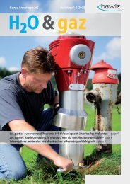
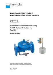
HAWIDO - REGELVENTILE<br />
HAWIDO - REGULATING VALVES<br />
Anleitung zu<br />
Instruction for<br />
Druckreduzierventil<br />
Pressure Reducing Valve<br />
Typ 1500<br />
DN40 - DN250<br />
Bewahren sie diese Anleitung am Ventilstandort auf!<br />
Keep this instruction in the close proximity of your valve<br />
Art Nr. 1500 900 999<br />
Mai 2011 – 1/plü
Beispiel Typenschild<br />
Tragen sie nach der Inbetriebnahme die folgenden Daten ein und verwenden sie diese zusätzlichen Angaben<br />
zu Ventiltyp Druck- und Durchflussverhältnisse bei Rücksprachen und Fragen mit dem Hersteller oder<br />
Lieferanten:<br />
Baujahr: ...................................................<br />
Seriennummer: ...................................................<br />
Example of a rating<br />
Once the commissioning work has been completed, enter the following data and always specify this additional<br />
information concerning the valve type, pressure and flow ratios, whenever you consult or have reason to<br />
question the manufacture or supplier:<br />
Year of manufacture: ...................................................<br />
Serial number: ...................................................<br />
Technische Änderungen vorbehalten!<br />
Subject to technical modifications!<br />
Ventiltyp und Nennweite PN Baujahr Seriennummer Prüfnorm<br />
Type of valve and size NP Year of manufacture Serial number Standard
INHALTSVERZEICHNIS<br />
-1-<br />
A. FUNKTION 3<br />
1. ARBEITSWEISE 3<br />
2. ALLGEMEINE SICHERHEITSHINWEISE 3<br />
3. EINBAUEMPFEHLUNG 4<br />
B. INBETRIEBNAHME 5<br />
1. FUNKTIONSSCHEMA (1500) 5<br />
2. VORBEREITUNG 5<br />
3. ENTLÜFTEN 5<br />
4. EINREGULIERUNG 6<br />
5. EINSTELLUNG DER REAKTIONSGESCHWINDIGKEIT 6<br />
6. DICHTHEITSPRÜFUNG 6<br />
C. WAS TUN BEI STÖRUNGEN? 7<br />
D. AUSSERBETRIEBNAHME UND WARTUNG 8<br />
1. AUSSERBETRIEBNAHME 8<br />
2. WARTUNG UND SERVICE 8<br />
2.1 ALLGEMEINES 8<br />
2.2 JÄHRLICHE FUNKTIONSKONTROLLEN 8<br />
2.3 4- BIS 5 JAHRES WARTUNG 9<br />
3. REPARATURSÄTZE UND ERSATZTEILE 11<br />
3.1 HAUPTVENTIL (ZEICHNUNG) 11<br />
3.2 HAUPTVENTIL (STÜCKLISTE) 12<br />
3.3 STEUERVENTIL DRUCKREDUZIERUNG (ZEICHNUNG) 15<br />
3.4 STEUERVENTIL DRUCKREDUZIERUNG (STÜCKLISTE) 16<br />
3.5 STEUERLEITUNG HAWIDO TYP 1500 DN40 BIS DN80 (ZEICHNUNG) 17<br />
3.6 STEUERLEITUNG HAWIDO TYP 1500 DN100 BIS DN125 (ZEICHNUNG) 18<br />
3.7 STEUERLEITUNG HAWIDO TYP 1500 DN150 BIS DN250 (ZEICHNUNG) 19<br />
3.8 STEUERLEITUNG HAWIDO TYP 1500 DN40 BIS DN65 (EINZELTEILE) 20<br />
3.9 STEUERLEITUNG HAWIDO TYP 1500 DN80 BIS DN125 (EINZELTEILE) 21<br />
3.10 STEUERLEITUNG HAWIDO TYP 1500 DN150 BIS DN250 (EINZELTEILE) 22<br />
3.11 OPTISCHER STELLUNGSANZEIGER (ZEICHNUNG) 23<br />
3.12 OPTISCHER STELLUNGSANZEIGER (STÜCKLISTE) 24<br />
E. ANHANG 25<br />
1. DREHMOMENTE 25<br />
2. ZERTIFIKATE 26<br />
2.1 SVGW ZERTIFIKAT 26<br />
2.2 DVGW ZERTIFIKAT 27<br />
F. HAWLE IN EUROPA 29
-2-<br />
G. DESCRIPTION 31<br />
1. FUNCTION 31<br />
2. GENERAL SAFETY GUIDELINES 31<br />
3. RECOMMENDED INSTALLATION 32<br />
H. COMMISSIONING 33<br />
1. OPERATION DI<strong>AG</strong>RAM (1500) 33<br />
2. PREPARATION 33<br />
3. VENTING 33<br />
4. SETTING 34<br />
5. SETTING THE REACTION SPEED 34<br />
6. CHECKING FOR LEAK<strong>AG</strong>E 34<br />
I. FAULT FINDING 35<br />
J. PUTTING OUT OF SERVICE AND MAINTENANCE 36<br />
1. PUTTING OUT OF SERVICE 36<br />
2. MAINTENANCE AND SERVICE 36<br />
2.1 GENERAL 36<br />
2.2 ANNUAL CHECKS 36<br />
2.3 FOUR OR FIVE YEARLY MAINTENANCE 37<br />
3. REPAIR KITS AND SPARE PARTS 39<br />
3.1 MAIN VALVE (DRAWING) 39<br />
3.2 MAIN VALVE (PARTS LIST) 40<br />
3.3 CONTROL VALVE PRESSURE REDUCING (DESIGN) 43<br />
3.4 CONTROL VALVE PRESSURE REDUCING (PARTS LIST) 44<br />
3.5 CONTROL LINE HAWIDO TYPE 1500 ND40 UP TO ND80 (DRAWING) 45<br />
3.6 CONTROL LINE HAWIDO TYPE 1500 ND100 UP TO ND125 (DRAWING) 46<br />
3.7 CONTROL LINE HAWIDO TYPE 1500 ND150 UP TO ND250 (DRAWING) 47<br />
3.8 CONTROL LINE HAWIDO TYPE 1500 ND40 UP TO ND65 (PARTS LIST) 48<br />
3.9 CONTROL LINE HAWIDO TYPE 1500 DN80 UP TO ND125 (PARTS LIST) 49<br />
3.10 CONTROL LINE HAWIDO TYPE 1500 ND150 UP TO ND300 (PARTS LIST) 50<br />
3.11 POSITION INDICATOR (DRAWING) 51<br />
3.12 POSITION INDICATOR (PARTS LIST) 52<br />
K. ANNEX 53<br />
1. TORQUE TABLE 53<br />
2. CERTIFICATES 54<br />
2.1 SVGW ZERTIFIKAT 54<br />
2.2 DVGW ZERTIFIKAT 55<br />
L. HAWLE IN EUROPE 57
A. Funktion<br />
1. Arbeitsweise<br />
-3-<br />
Das Druckreduzierventil reduziert einen variablen Eingangsdruck (p1) auf einen praktisch konstanten,<br />
tieferen Ausgangsdruck (p2). Schwankender Durchfluss und Eingangsdruck haben keine Auswirkung auf<br />
den vom Steuerventil geregelten Ausgangsdruck. Der Ausgangsdruck (p2) ist im Bereich von 1 bis 15 bar<br />
(Standard) einstellbar.<br />
Technische Merkmale:<br />
Medium: Trinkwasser<br />
Druckstufen: PN10 (ab DN200 Standard)<br />
PN16 (bis DN150 Standard)<br />
PN25<br />
Flansche: Anschlussmasse nach DIN EN 1092 - 2<br />
Material Hauptventil: GGG 40<br />
Temperaturbereich: 2 – 40°C<br />
2. Allgemeine Sicherheitshinweise<br />
Vor der Inbetriebnahme muss diese Anleitung sorgfältig durchgelesen und verstanden werden. Bei<br />
unsachgemässer Installation, Inbetriebnahme, Bedienung und Wartung können sowohl Sach- als auch<br />
Personenschäden entstehen.<br />
Das <strong>Hawle</strong>-Regelventil (HAWIDO) ist ausgelegt für den Einsatz in der Trinkwasserversorgung.<br />
Andere Einsatzmedien nur nach Rücksprache mit dem Hersteller.<br />
Die technischen Regelwerke (z.B. SVGW, ÖVGW, DVGW ...) und Vorschriften (z.B. VDE, VDI ...), Gesetze<br />
und Normen werden als bekannt vorausgesetzt und sind einzuhalten bzw. anzuwenden.<br />
Arbeiten an elektrischen Anlagen (z.B. bei Einbau von Magnetpositionsschaltern, Magnetventilen, usw.)<br />
dürfen nur von dazu befugtem Personal durchgeführt werden.<br />
Grundsätzlich ist für die Anordnung, die Einbaulage, die Installation und Inbetriebnahme der <strong>Armaturen</strong> in<br />
der Rohrleitung der Planer, die Baufirma bzw. Betreiber verantwortlich. Planungs- oder Einbaufehler können<br />
die sichere Funktion des Regelventils beeinträchtigen und ein beachtliches Gefährdungspotential darstellen.<br />
Im Zweifelsfall ist mit uns Rücksprache zu halten.
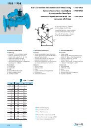
3. Einbauempfehlung<br />
-4-<br />
Vor dem Einbau der Armatur sind die Rohrleitungen sorgfältig durchzublasen bzw. zu spülen, so dass keine<br />
Fremdkörper wie Holzstücke, Steine usw. in das Regelventil eindringen können.<br />
Bauteile<br />
A Absperrschieber<br />
B Regelventil<br />
C Schmutzfänger<br />
D Ein-/Ausbaustück<br />
Das HAWIDO muss waagrecht, (andere Bauarten auf Anfrage) mit dem Ventildeckel nach oben, eingebaut<br />
werden. Wir empfehlen, einen Absperrschieber und einen Schmutzfänger vor dem Ventil sowie einen<br />
Absperrschieber am Ausgang zu montieren. Vor der Inbetriebnahme muss geprüft werden, dass kein grober<br />
Fremdkörper ins HAWIDO eindringen kann.<br />
Für andere Einbauarten bitten wir um Rücksprache.
B. Inbetriebnahme<br />
1. Funktionsschema (1500)<br />
2. Vorbereitung<br />
-5-<br />
Bestandteile<br />
1 Hauptventil<br />
2 Kugelhahn (A, B, C)<br />
3 Filter<br />
4 Blende<br />
5 Drosselrückschlagventil<br />
6 Steuerventil<br />
7 Manometer (A, B)<br />
8 optischer Stellungsanzeiger<br />
el. Stellungsanzeiger (Option)<br />
Ventil-Öffnungsbegrenzer (Option)<br />
Vor Inbetriebnahme des Ventils muss sichergestellt werden, dass die Schieber auf der Ein- und<br />
Ausgangsseite geschlossen sind und die Flanschverbindungen dicht verschraubt sind.<br />
Am Ventil<br />
sind die Kugelhähne (2A und 2B) zu öffnen und ist die Kontermutter der Einstellschraube auf dem<br />
Drosselrückschlagventil (5) zu lösen<br />
die Einstellschraube am Drosselrückschlagventil (5) ist um ca. 10 Umdrehungen herauszudrehen<br />
(Leitung in die Steuerkammer ist offen).<br />
ist der Kugelhahn (2C) zu schliessen.<br />
ist der Gewindestift im zentralen Stopfen auf dem Stellungsanzeiger um wenige Umdrehungen zu<br />
lösen.<br />
ist eine Schraubverbindung der Steuerleitung an der höchsten Stelle leicht zu lösen<br />
(ca. 1 Umdrehung).<br />
ist die Schraube am Handrad des Steuerventils für Druckreduzierung (6) zu lösen, das Handrad<br />
nach links drehen bis von der Feder kein Widerstand zu spüren ist.<br />
3. Entlüften<br />
Ablauf:<br />
Den Gewindestift auf dem Stopfen des optischen Stellungsanzeiger mit einem Schraubenzieher 2 – 3<br />
Umdrehungen lösen (Achtung: Gewindestift nicht ganz herausdrehen!).<br />
Den Absperrschieber auf der Eingangsseite langsam soweit öffnen, dass Wasser in das Ventil fliesst. Das<br />
Ventil füllt sich mit Wasser und die Luft entweicht über die leicht geöffneten Schraubverbindungen und den<br />
Entlüftungsbohrungen im Stopfen.<br />
Ist durch den Entlüftungsvorgang des Ventils in der Steuerleitung alle Luft entwichen, den Gewindestift und<br />
die gelöste Schraubverbindung wieder anziehen. Alle Verschraubungen auf Dichtheit kontrollieren und falls<br />
erforderlich nachziehen.<br />
Eingangsschieber langsam vollständig öffnen.
-6-<br />
Kontrolle: Wird der Absperrschieber auf der Ausgangsseite leicht geöffnet, so muss das Ventil schliessen<br />
bzw. geschlossen bleiben. Absperrschieber anschliessend wieder schliessen.<br />
Schliesst das Ventil nicht, ist die Inbetriebnahme ab vorhergehendem Kapitel zu wiederholen. Hier ist<br />
insbesondere auf das Entlüften der Steuerleitungen und der oberen Ventilkammer zu achten.<br />
4. Einregulierung<br />
Das Ventil ist gemäss vorhergehenden Kapiteln vorbereitet. Der Schieber auf der Eingangsseite ist offen und<br />
der Schieber auf der Ausgangsseite ist geschlossen.<br />
Ablauf:<br />
Kugelhahn (2C) langsam öffnen; das Ventil öffnet und füllt die Leitung auf der Ausgangsseite bis zu<br />
einem Druck von ca. 0,4 bar, danach schliesst das Ventil wieder.<br />
Den Absperrschieber auf der Ausgangsseite langsam schrittweise öffnen; das Ventil schliesst, wenn<br />
die Ausgangsleitung gefüllt ist und kein Wasserverbrauch vorhanden ist. Dieser Vorgang kann je<br />
nach Leitungssystem bis zu einigen Minuten dauern.<br />
Erzeugen Sie einen für die Nennweite normalen Wasserverbrauch (z.B. durch Öffnen eines<br />
Hydranten), damit mit dem Handrad am Steuerventil (6) der Ausgangsdruck eingestellt werden kann<br />
(durch Drehen nach rechts steigt der Ausgangsdruck).<br />
Anmerkung<br />
Zwischen jeder halben Umdrehung des Handrades warten, bis sich das hydraulische System stabilisiert hat.<br />
Den Druck auf der Ausgangsseite mit dem Manometer prüfen.<br />
Ist der gewünschte Ausgangsdruck (Fliessdruck oder statischer Druck- die Differenz beträgt ca. 0,5 bar)<br />
eingestellt, ist die Schraube am Handrad des Steuerventils anzuziehen.<br />
5. Einstellung der Reaktionsgeschwindigkeit<br />
Arbeitet das HAWIDO nicht ruhig, oder entstehen Druckstösse im Leitungsnetz, so kann dies mit der<br />
entsprechenden Einstellung des Drosselrückschlagventil (5) korrigiert werden.<br />
Vorgang:<br />
Kontermutter lösen. Mit dem Schraubenzieher die Einstellschraube im Uhrzeigersinn hineindrehen, bis das<br />
Ventil ruhig arbeitet. Danach die Kontermutter anziehen.<br />
Vorsicht<br />
Die Einstellschraube muss immer mindestens 3 - 5 Umdrehungen offen sein, weil sonst das Ventil nach dem<br />
Schliessvorgang nicht mehr genügend schnell öffnet. Bei sehr hohen Eingangsdrücken spezielle Einstellung<br />
erforderlich.<br />
6. Dichtheitsprüfung<br />
HAWIDO’s werden vor Auslieferung im Werk auf ihre Dichtheit und Funktionsfähigkeit überprüft. Bei der<br />
Dichtheitsprüfung unter Betriebsbedingungen ist daher insbesondere auf die Dichtheit der<br />
Flanschverbindungen, der Steuerleitungen und des zentralen Stopfens auf dem Ventildeckel zu achten.<br />
Eventuell durch Nachziehen der Verbindungen die Dichtheit sicherstellen.
C. Was tun bei Störungen?<br />
Vorkommnis Mögliche Ursache Massnahme<br />
-7-<br />
Ventil öffnet nicht Drosselrückschlagventil<br />
verstopft<br />
Drosselrückschlagventil zu weit<br />
geschlossen<br />
Ventil schliesst nicht Drosselrückschlagventil<br />
verstopft<br />
austauschen oder mehrmals<br />
Madenschraube<br />
herausschrauben bis Ventil<br />
arbeitet<br />
Madenschraube<br />
herausschrauben bis Ventil<br />
arbeitet<br />
austauschen oder mehrmals<br />
Madenschraube komplett<br />
einschrauben, komplett<br />
herausschrauben, neu<br />
einstellen<br />
reinigen<br />
Filter in der Steuerleitung<br />
verstopft<br />
Luft in der Steuerleitung / obere<br />
Ventilkammer<br />
entlüften<br />
Fremdkörper im Basisventil Wartung durchführen,<br />
Fremdkörper entfernen<br />
Membrane defekt Wartung durchführen,<br />
Membrane austauschen<br />
Ventilspindel durch<br />
Wartung durchführen,<br />
Inkrustierung verklemmt Inkrustierung entfernen<br />
lautes Geräusch ungünstige Betriebsverhältnisse Druckverhältnisse um ca. 0,1<br />
bis 0,2 bar verändern<br />
Drosselrückschlagventil etwas<br />
öffnen oder schliessen;<br />
Aussendienst der Firma <strong>Hawle</strong><br />
verständigen<br />
Falsche Ventilnennweite Richtige Nennweite berechnen<br />
lassen (Firma <strong>Hawle</strong>)<br />
Unruhige Arbeitsweise Drosselrückschlagventil falsch neu einstellen (gemäss Kapitel:<br />
eingestellt<br />
Einstellen der<br />
Reaktionsgeschwindigkeit)<br />
Ursprüngliche Druckwerte Manometer defekt Manometer prüfen / aus-<br />
werden nicht erreicht<br />
tauschen<br />
Veränderte Betriebsverhältnisse neu einregulieren (siehe<br />
Kapitel: Einregulieren)<br />
EWS-Beschichtung beschädigt Transportschaden;<br />
Ausbessern mit <strong>Hawle</strong>-Zwei-<br />
Einbauschaden<br />
Komponenten-Reparatur-Set für<br />
Beschichtungen
D. Ausserbetriebnahme und Wartung<br />
1. Ausserbetriebnahme<br />
Das arbeitende Ventil muss zuerst nach folgendem Vorgehen hydraulisch geschlossen werden:<br />
Langsam den Schieber nach und den Schieber vor dem Ventil schliessen.<br />
Langsam die Kugelhahnen (2A, 2B und 2C) schliessen.<br />
Das Ventil ist ausser Betrieb genommen und es kann eine Wartung durchgeführt werden.<br />
2. Wartung und Service<br />
2.1 Allgemeines<br />
-8-<br />
Durch unsere langjährige Erfahrung mit eigenmediumgesteuerten Membran-Regelventilen wissen wir, dass<br />
unsere HAWIDO’s über Jahre störungsfrei arbeiten. Voraussetzung dafür ist allerdings eine regelmässige<br />
Wartung.<br />
Bei normalen Betriebsbedingungen sollte:<br />
Einmal pro Jahr das Ventil auf Funktionstüchtigkeit überprüft werden (Funktionskontrolle)<br />
Einmal pro Jahr der Schmutzfänger vor dem Ventil und der Filter der Steuerleitung gereinigt werden<br />
Alle 4 - 5 Jahre die beweglichen Innenteile kontrolliert und Verschleissteile ersetzt werden (Wartung)<br />
Bei ungewöhnlichen Betriebsbedingungen (z.B. schwebstoffreichem Wasser, sehr grosse Druckreduzierung,<br />
geringe Durchflussmenge usw.) sollten die Funktionskontrollen und Wartungsarbeiten öfter erfolgen.<br />
Hinweisschild Wartung<br />
xx steht für das jeweilige Jahr.<br />
2.2 Jährliche Funktionskontrollen<br />
Reinigung des Schmutzfängers (Hauptleitung)<br />
Deckel abschrauben<br />
reinigen (Bürste, Lappen usw.) oder ersetzen des Siebes<br />
Sieb einbauen und Deckel wieder anschrauben<br />
Reinigung des Filters (Steuerleitung)<br />
Filterdeckel abschrauben<br />
reinigen (Bürste, Lappen usw.) oder ersetzen des Filtersiebes<br />
Sieb einbauen und Filterdeckel wieder anschrauben<br />
Kontrolle des Ventils<br />
Optischer Stellungsanzeiger entfernen.<br />
Leichtgängigkeit der Ventilspindel überprüfen durch Anheben und Absenken mit Gewindestange.<br />
Optischer Stellungsanzeiger montieren
Wiederinbetriebnahme<br />
gemäss Abschnitt Inbetriebnahme<br />
-9-<br />
Funktionskontrolle des Ventils<br />
Achtung: Um bei der nachstehend beschriebenen Funktionskontrolle Druckstösse zu vermeiden, muss bei<br />
grossen Durchflussmengen diese durch langsames schliessen des Eingangsschieber vor dem Ventil<br />
gedrosselt werden.<br />
Langsam den Kugelhahn (2C) schliessen; Ventil muss schliessen.<br />
Langsam den Kugelhahn (2C) öffnen; Ventil muss öffnen.<br />
2.3 4- bis 5 Jahres Wartung<br />
Schmutzfänger (Hauptleitung)<br />
Deckel abschrauben<br />
Reinigen oder ersetzen des Siebes<br />
Sieb einbauen und Deckel wieder anschrauben<br />
Filter (Steuerleitung)<br />
Filterdeckel abschrauben<br />
Reinigen oder ersetzen des Filtersiebes<br />
Sieb einbauen und Filterdeckel wieder anschrauben<br />
Basisventil (siehe Kapitel: Reparatursätze und Ersatzteile)<br />
lösen der Verschraubungen und ganze Steuerleitung beiseite legen<br />
Demontage des optischen Stellungsanzeigers und auswechseln der Dichtungen<br />
lösen der Deckelschrauben, Deckel abnehmen<br />
Sichtprüfung aller Innenteile auf Verschleiss, Verschmutzung und Verkalkung<br />
reinigen der Innenteile, des Sitzes und des Gehäuseinnenraumes inklusive Deckel<br />
austauschen der Membrane, des O-Rings und eventuell der Sitzdichtung<br />
einfetten der Spindelführungsbereiche mit einem lebensmitteltauglichen Fett. Überprüfung der<br />
Leichtgängigkeit der Spindel in der Gehäuseführung und in der Deckelführung<br />
zusammenbauen des Basisventils (Drehmomente siehe Tabelle im Anhang). Bei der Montage muss<br />
die Leichtgängigkeit der Spindel mit einer Gewindestange durch Anheben und Absenken mehrmals<br />
überprüft werden<br />
Auseinanderbauen Steuerventil (siehe Kapitel: Reparatursätze und Ersatzteile)<br />
Die Schraube am Handrad lösen<br />
Das Handrad nach links drehen, bis von der Feder keinen Widerstand zu spüren ist<br />
lösen der Gehäuseschrauben<br />
lösen der Führungszapfen Pos. 8 und lösen des Dichtungsträgers Pos. 6<br />
austauschen der Membrane, der O-Ringe und eventuell des Dichtungsträgers<br />
Sichtprüfung des Gehäuseinnenraumes und ev. reinigen, inkl. Glocke<br />
zusammenbauen des Steuerventils (Drehmomente siehe Tabelle im Anhang).<br />
Funktionskontrolle des Drosselrückschlagventils<br />
lösen der Kontermutter<br />
hineindrehen der Drosselschraube, anschliessend bis zum Anschlag herausdrehen<br />
einige Umdrehungen wieder einschrauben; dieser Vorgang muss leichtgängig erfolgen können
Wiederinbetriebnahme<br />
gemäss Kapitel Inbetriebnahme<br />
-10-<br />
Funktionskontrolle des Ventils<br />
Achtung: Um bei der nachstehend beschriebenen Funktionskontrolle Druckstösse zu vermeiden, muss bei<br />
grossen Durchflussmengen diese durch langsames schliessen des Eingangsschieber vor dem Ventil<br />
gedrosselt werden.<br />
Langsam den Kugelhahn (2C) schliessen; Ventil muss schliessen.<br />
Langsam den Kugelhahn (2C) öffnen; Ventil muss öffnen.<br />
Nach der Funktionskontrolle ist der Schieber auf der Eingangsseite vollständig zu öffnen. Prüfen sie, ob der<br />
Schieber auf der Ausgangsseite vollständig offen ist.
-11-<br />
3. Reparatursätze und Ersatzteile<br />
Für die 4 bzw. 5-Jahres-Durchsicht werden normalerweise einige Ersatzteile benötigt, diese erhalten Sie als<br />
Reparaturset für:<br />
das Basisventil<br />
das Steuerventil<br />
die Steuerleitung<br />
optischer Stellungsanzeiger<br />
Die Art. Nummern entnehmen sie den Stücklisten und Ersatzteillisten. Achtung: Bei Bestellung von<br />
Ersatzteilen immer Ventiltyp, Seriennummer und Baujahr angeben!<br />
Wichtig:<br />
Ersatzteile aus EPDM (Membranen, Dichtungen) und NBR (O-Ringe) müssen an einem dunklen Ort, vor UV<br />
Strahlung geschützt, gelagert werden!<br />
Haltbarkeit bei dunkler Lagerung:<br />
EPDM: 8 Jahre ab Herstellung<br />
NBR: 5 Jahre ab Herstellung<br />
3.1 Hauptventil (Zeichnung)<br />
Stand: 20.1.2006/EI
3.2 Hauptventil (Stückliste)<br />
Pos. Beschreibung Material Artikelnummer<br />
-12-<br />
DN 40 DN 50 DN 65 DN 80 DN 100<br />
1 Gehäuse GGG 40 1004 040 000 1004 050 000 1004 065 000 1004 080 000 1004 100 000<br />
2 Deckel GGG 40 1014 050 000° 1014 050 000° 1014 065 000 1014 080 000 1014 100 000<br />
3 Führungszapfen Bronze 1024 050 000 1024 050 000 1024 065 000 1024 080 000 1024 100 000<br />
4 Spindel INOX 1026 050 000 1026 050 000 1026 065 000 1026 080 000 1026 100 000<br />
5 Sitz INOX * * * * *<br />
6 Gegensitz INOX 1044 040 001 1044 050 001 1044 065 001 1044 080 001 1044 100 001<br />
7 Dichtung EPDM 1022 040 000 1022 050 000 1022 065 000 1022 080 000 1022 100 000<br />
8 Dichtungsträger INOX 1027 040 200 1027 050 200 -- -- --<br />
Dichtungsträger GG 25 -- -- 1027 065 000 1027 080 000 1027 100 000<br />
9 Membrane PN10/16 EPDM 1020 050 000 1020 050 000 1020 065 000 1020 080 000 1020 100 000<br />
Membrane PN25 EPDM 1020 050 000 1020 050 000 1021 065 000 1021 080 000 1021 100 000<br />
10 Druckscheibe INOX 1047 050 000 1047 050 000 -- -- --<br />
Druckscheibe GGG 40 -- -- 1046 065 000 1046 080 000 1046 100 000<br />
11 Mutter INOX 0007 710 080 0007 710 080 0007 712 080 0007 716 080 0007 716 080<br />
12 Feder INOX 1049 050 000 1049 050 000 1049 065 000 1049 080 000 1049 100 000<br />
Feder für Ventile<br />
senkrecht eingebaut<br />
INOX 1050 050 000 1050 050 000 1050 065 000 1050 080 000 1050 100 000<br />
13 Deckelführung Bronze 1042 050 000 1042 050 000 1042 065 000 1042 080 100 1042 080 100<br />
14 Sechskantschraube INOX 0006 408 020 0006 408 020 0006 410 025 0006 410 025 0006 412 025<br />
15 O-Ring NBR 0180 017 126 0180 017 126 0180 017 126 0180 020 025 0180 020 025<br />
16 Scheibe INOX 0008 208 000 0008 208 000 0008 210 000 0008 210 000 0008 212 000<br />
17 GSK-Kleber 1099 900 000 1099 900 000 1099 900 000 1099 900 000 1099 900 000<br />
18 Wartungskleber -- -- -- -- --<br />
Hauptventil komplett PN10/16 1200 040 000 1200 050 000 1200 065 000 1200 080 000 1200 100 000<br />
Hauptventil komplett PN25 -- -- 1200 065 025 1200 080 025 1200 100 025<br />
Reparaturset bestehend<br />
aus: Pos. 7, 9, 15 und 18<br />
PN10/16 1080 040 000 1080 050 000 1080 065 000 1080 080 000 1080 100 000<br />
PN25 1080 040 000 1080 050 000 1081 065 000 1081 080 000 1081 100 000<br />
° bei Dimensionen DN40 und DN50 Deckel mit ½“ Gewinde; ab Seriennummer 14732 (ca. Ende Juli 2003)<br />
* nicht austauschbar<br />
Stand: 11.03.2008 – 1/plü
-13-<br />
Pos Beschreibung Material Artikelnummer<br />
DN 125<br />
DN 150 DN 200° DN 200^<br />
1 Gehäuse GGG 40 1004 125 000 1004 151 000 1004 200 000 1004 200 016<br />
2 Deckel GGG 40 1014 125 000 1014 151 000 1014 200 000 1014 200 000<br />
3 Führungszapfen Bronze 1024 125 150 1024 125 150 1024 200 250 1024 200 250<br />
4 Spindel INOX 1026 125 000 1026 151 000 1026 200 000 1026 200 000<br />
5 Sitz INOX * * * *<br />
6 Gegensitz INOX 1044 125 001 1044 150 001 1044 200 001 1044 200 001<br />
7 Dichtung EPDM 1022 125 150 1022 151 000 1022 200 000 1022 200 000<br />
8 Dichtungsträger GG 25 1027 125 150 1027 151 000 1027 200 000 1027 200 000<br />
9 Membrane PN10/16 EPDM 1020 125 150 1020 151 000 1020 200 000 1020 200 000<br />
Membrane PN25 CR 1051 125 150 1051 151 000 -- 1034 200 000<br />
10 Druckscheibe GGG 40 1046 125 150 1046 151 000 1046 200 000 1046 200 000<br />
11 Mutter INOX 0007 720 080 0007 720 080 0007 724 080 0007 724 080<br />
12 Feder INOX 1049 125 150 1049 151 150 1049 200 000 1049 200 000<br />
Feder für Ventile<br />
senkrecht eingebaut<br />
INOX 1050 125 150 1050 151 000 1050 200 000 1050 200 000<br />
13 Deckelführung Bronze 1042 125 150 1042 125 150 1042 200 250 1042 200 250<br />
Deckelführung zu starker<br />
Feder (Nr. 1050)<br />
Bronze 1042 904 150 1042 904 150 -- --<br />
14 6-Kt. Schraube INOX 0006 416 035 0006 416 035 0006 420 045 0006 420 045<br />
15 O-Ring NBR 0180 026 030 0180 026 030 0180 030 040 0180 030 040<br />
16 Scheibe INOX 0008 216 000 0008 216 000 0008 220 000 0008 220 000<br />
17 GSK-Kleber 1099 900 000 1099 900 000 1099 900 000 1099 900 000<br />
18 Wartungskleber -- -- -- --<br />
21 Haltelasche INOX -- -- 1200 900 020 1200 900 020<br />
Hauptventil komplett PN10/16 1200 125 000 1200 151 000 1200 200 000 1200 200 016<br />
Hauptventil komplett PN25 1200 125 025 1200 151 025 1200 200 025 --<br />
Reparaturset<br />
bestehend aus: Pos.<br />
7,9,15,18<br />
(DN150-DN200)<br />
° PN10;<br />
^ PN16<br />
* nicht austauschbar<br />
Stand: 11.03.2008 – 1/plü<br />
PN10/16 1080 125 150 1080 151 000 1080 200 000 1080 200 000<br />
PN25 1081 125 150 1081 151 000 1081 200 000 1081 200 000
° PN10<br />
^ PN16<br />
-14-<br />
Pos Beschreibung Material Artikelnummer<br />
DN 250° DN 250^<br />
1 Gehäuse GGG 40 1004 250 000 1004 250 016<br />
2 Deckel GGG 40 1014 250 000 1014 250 000<br />
3 Führungszapfen Bronze 1024 200 250 1024 200 250<br />
4 Spindel INOX 1026 250 000 1026 250 000<br />
5 Sitz INOX 1040 250 000 1040 250 000<br />
6 Gegensitz INOX 1044 250 001 1044 250 001<br />
7 Dichtung EPDM 1022 250 000 1022 250 000<br />
8 Dichtungsträger GG 25 1027 250 000 1027 250 000<br />
9 Membrane EPDM 1020 250 000 --<br />
Membrane CR -- 1034 250 000<br />
10 Druckscheibe GGG 40 1046 250 000 1046 250 000<br />
11 Mutter INOX 0007 724 080 0007 724 080<br />
12 Feder INOX 1049 250 000 1049 250 000<br />
13 Deckelführung Bronze 1042 200 250 1042 200 250<br />
14 6-Kt. Schraube INOX 0006 420 045 0006 420 045<br />
15 O-Ring NBR 0180 030 040 0180 030 040<br />
16 Scheibe INOX 0008 220 000 0008 220 000<br />
17 GSK-Kleber 1099 900 000 1099 900 000<br />
18 Wartungskleber -- --<br />
19 I-6-Kt-Schraube INOX 0003 708 025 0003 708 025<br />
20 Sitzdichtung NBR 1056 900 250 1056 900 250<br />
21 Haltelasche INOX 1200 900 020 1200 900 020<br />
Hauptventil komplett 1200 250 000 1200 250 016<br />
Reparaturset<br />
bestehend aus: Pos.<br />
Pos. 7,9,15,18,20<br />
(DN250)<br />
Stand: 11.03.2008 – 1/plü<br />
PN 10/16 1080 250 000 1080 250 000
-15-<br />
3.3 Steuerventil Druckreduzierung (Zeichnung)<br />
Stand: 20.1.2003/EI
-16-<br />
3.4 Steuerventil Druckreduzierung (Stückliste)<br />
Pos. Beschreibung Material Artikelnummer<br />
PN 16/25<br />
1 Gehäuse RG 5 1100 012 000<br />
2 Glocke kurz RG 5 1108 012 000<br />
3 Sitz INOX 1117 012 000<br />
4 Bügel INOX 1136 000 000<br />
5 O-Ring NBR 0180 007 515<br />
6 Dichtungsträger INOX/NBR 1120 012 000<br />
7 O-Ring NBR 0180 020 025<br />
8 Führungszapfen Bronze 1137 000 000<br />
9 Membrane EPDM 1121 000 000<br />
10 Druckscheibe Bronze 1129 012 000<br />
11 Spannscheibe INOX 0008 708 000<br />
12 Mutter INOX 0007 208 050<br />
13 Dichtung Fiber 0132 025 010<br />
14 Druckschraube INOX 1133 000 000<br />
15 Druckmutter Bronze 1134 000 000<br />
16 Regulierschraube PV 30 1135 000 000<br />
17 Flachkopfschraube INOX 0011 205 008<br />
18 Zylinderschraube INOX 0004 506 016<br />
19 Feder standard INOX 1145 000 000<br />
Stand: 22.4.2005/TBO<br />
Feder schwach, lange Ausführung INOX 1147 000 000<br />
Regelbereich:<br />
Steuerventil komplett (Standard) 1.5 – 15bar 1900 012 000<br />
Steuerventil komplett (lange<br />
Ausführung mit blauer<br />
Kennzeichnungsfolie)<br />
0.2 – 5bar 1902 012 100<br />
Reparatursatz bestehend aus:<br />
Pos. 5,6,7 und 9 1180 000 000
3.5 Steuerleitung HAWIDO Typ 1500 DN40 bis DN80 (Zeichnung)<br />
Stand: 20.1.2003/EI<br />
-17-
3.6 Steuerleitung HAWIDO Typ 1500 DN100 bis DN125 (Zeichnung)<br />
Stand: 20.1.2003/EI<br />
-18-
3.7 Steuerleitung HAWIDO Typ 1500 DN150 bis DN250 (Zeichnung)<br />
Stand: 20.1.2003/EI<br />
-19-
3.8 Steuerleitung HAWIDO Typ 1500 DN40 bis DN65 (Einzelteile)<br />
-20-<br />
Pos. Beschreibung Material Artikelnummer<br />
DN 40 DN 50 DN 65<br />
1 Dichtung St./NBR 0130 016 000° 0130 016 000° 0130 016 000<br />
2 Blende INOX 0284 019 000 0284 019 000 0284 024 000<br />
3 Verschraubung INOX 0311 012 012 0311 012 012 0311 012 012<br />
4 Übergangsmuffe INOX 0361 012 012 0361 012 012 0361 012 012<br />
5 Übergangsnippel INOX 0371 012 012 0371 012 012 0371 012 012<br />
6 Einstellnippel INOX 0411 012 012 0411 012 012 0411 012 012<br />
7 Einschraubwinkel INOX 0431 012 012 0431 012 012 0431 012 012<br />
8 Anschlusswinkel INOX 0455 012 000 0455 012 000 0455 012 000<br />
9 T - Verschraubung INOX 0461 012 000 0461 012 000 0461 012 000<br />
10 Stopfen INOX 0511 016 000° 0511 016 000° 0511 016 000<br />
11 Stopfen INOX 0510 012 000 0510 012 000 0510 012 000<br />
12 Kugelhahn INOX 0541 012 001 0541 012 001 0541 012 001<br />
14 Schrägfilter INOX 0545 112 001 0545 112 001 0545 112 001<br />
15 Drosselrückschlagventil Messing 0549 000 000 0549 000 000 0549 000 000<br />
16 Manometer* INOX 0600 xxx xxx 0600 xxx xxx 0600 xxx xxx<br />
17 Rohrdoppelnippel INOX 0680 012 030 0680 012 030 0680 012 030<br />
18 Rohrdoppelnippel INOX 0680 012 050 0680 012 050 0680 012 050<br />
19 Rohrdoppelnippel INOX 0680 012 060 0680 012 060 0680 012 060<br />
20 Rohrleitungsteile INOX d 12x1.5 d 12x1.5 d 12x1.5<br />
21 Hauptventil - 1200 040 000 1200 050 000 1200 065 000<br />
22 Druckreduzier-Steuerventil - 1900 012 000 1900 012 000 1900 012 000<br />
23 Filtersieb INOX 0545 900 001 0545 900 001 0545 900 001<br />
24<br />
Dichtung gross zu<br />
Schrägfilter<br />
POM 0545 112 011 0545 112 011 0545 112 011<br />
25/28/29 Stopfen zu Schrägfilter kpl. INOX/NBR 0545 112 010 0545 112 010 0545 112 010<br />
26 Hammerschraube INOX 0009 618 476 0009 618 476 0009 618 476<br />
27 Typenschild HAWIDO Alu 1099 900 040 1099 900 040 1099 900 040<br />
Reparaturset bestehend<br />
aus: Pos. 1, 23, 24 -<br />
1188 040 050<br />
1188 065 100°<br />
1188 040 050<br />
1188 065 100°<br />
1188 065 100<br />
* Druckbereich angeben (0 - 6 bar; 0 - 10 bar; 0 - 16 bar, 0-25 bar, 0-40 bar)<br />
° Pos.1 und 10: Stopfen bei Dimensionen DN40 und DN50 ab Seriennummer 14732 neu ½“ Gewinde (ende Juli 2003)<br />
Stand: 13.1.2006/TBO
3.9 Steuerleitung HAWIDO Typ 1500 DN80 bis DN125 (Einzelteile)<br />
-21-<br />
Pos. Beschreibung Material Artikelnummer<br />
DN 80 DN 100 DN 125<br />
1 Dichtung St./NBR 0130 016 000 0130 016 000 0130 025 000<br />
2 Blende INOX 0284 024 000 0284 031 000 0284 031 000<br />
3 Verschraubung INOX 0311 012 012 0311 012 012 0311 012 012<br />
4 Übergangsmuffe INOX 0361 012 012 0361 012 012 0361 012 012<br />
5 Übergangsnippel INOX 0371 012 012 0371 012 012 0371 012 012<br />
6 Einstellnippel INOX 0411 012 012 -- --<br />
7 Einschraubwinkel INOX 0431 012 012 0431 012 012 0431 012 012<br />
8 Anschlusswinkel INOX 0455 012 000 0455 012 000 0455 012 000<br />
9 T - Verschraubung INOX 0461 012 000 0461 012 000 0461 012 000<br />
10 Stopfen INOX 0511 016 000 0511 016 000 0511 025 000<br />
11 Stopfen INOX 0510 012 000 0510 012 000 0510 012 000<br />
12 Kugelhahn INOX 0541 012 001 0541 012 001 0541 012 001<br />
14 Schrägfilter INOX 0545 112 001 0545 112 001 0545 112 001<br />
15 Drosselrückschlagventil Messing 0549 000 000 0549 000 000 0549 000 000<br />
16 Manometer* INOX 0600 xxx xxx 0600 xxx xxx 0600 xxx xxx<br />
17 Rohrdoppelnippel INOX 0680 012 030 0680 012 040 0680 012 040<br />
18 Rohrdoppelnippel INOX 0680 012 050 0680 012 050 0680 012 060<br />
19 Rohrdoppelnippel INOX 0680 012 060 0680 012 060 0680 012 060<br />
20 Rohrleitungsteile INOX d 12x1.5 d 12x1.5 d 12x1.5<br />
21 Hauptventil - 1200 080 000 1200 100 000 1200 125 000<br />
22 Druckreduzier-Steuerventil - 1900 012 000 1900 012 000 1900 012 000<br />
23 Filtersieb INOX 0545 900 001 0545 900 001 0545 900 001<br />
24<br />
Dichtung gross zu<br />
Schrägfilter<br />
25/28/29 Stopfen zu Schrägfilter kpl.<br />
POM 0545 112 011 0545 112 011 0545 112 011<br />
INOX/<br />
NBR<br />
0545 112 010 0545 112 010 0545 112 010<br />
26 Hammerschraube INOX 0009 618 476 0009 618 476 0009 618 476<br />
27 Typenschild HAWIDO Alu 1099 900 040 1099 900 040 1099 900 040<br />
Reparaturset bestehend<br />
aus: Pos. 1, 23, 24 - 1188 065 100 1188 065 100 1188 125 300<br />
* Druckbereich angeben (0 - 6 bar; 0 - 10 bar; 0 - 16 bar, 0-25 bar, 0-40 bar)<br />
Stand: 13.1.2006/TBO
3.10 Steuerleitung HAWIDO Typ 1500 DN150 bis DN250 (Einzelteile)<br />
Pos. Beschreibung Material Artikelnummer<br />
-22-<br />
DN 150 DN 200 DN 250<br />
1 Dichtung St./NBR 0130 025 000 0130 025 000 0130 025 000<br />
2 Blende INOX 0284 031 000 0284 031 000 0284 031 000<br />
3 Verschraubung INOX 0311 012 012 0311 012 012 0311 012 012<br />
4 Übergangsmuffe INOX 0361 012 012 0361 012 012 0361 012 012<br />
5 Übergangsnippel INOX 0371 012 012 0371 012 012 0371 012 012<br />
6 Einstellnippel INOX -- -- --<br />
7 Einschraubwinkel INOX 0431 012 012 0431 012 012 0431 012 012<br />
8 Anschlusswinkel INOX 0455 012 000 0455 012 000 0455 012 000<br />
9 T - Verschraubung INOX 0461 012 000 0461 012 000 0461 012 000<br />
10 Stopfen INOX 0511 025 000 0511 025 000 0511 025 000<br />
11 Stopfen INOX 0510 012 000 0510 012 000 0510 016 000<br />
12 Kugelhahn INOX 0541 012 001 0541 012 001 0541 012 001<br />
14 Schrägfilter INOX 0545 112 001 0545 112 001 0545 112 001<br />
15 Drosselrückschlagventil Messing 0549 000 000 0549 000 000 0549 000 000<br />
16 Manometer* INOX 0600 xxx xxx 0600 xxx xxx 0600 xxx xxx<br />
17 Rohrdoppelnippel INOX 0680 012 030 0680 012 030 --<br />
18 Rohrdoppelnippel INOX 0680 012 060 0680 012 080 0680 012 060<br />
19 Rohrdoppelnippel INOX 0680 012 060 0680 012 080 0690 016 012<br />
20 Rohrleitungsteile INOX d 12x1.5 d 12x1.5 d 12x1.5<br />
21 Hauptventil - 1200 151 000 1200 200 000 1200 250 000<br />
22 Druckreduzier-Steuerventil - 1900 012 000 1900 012 000 1900 012 000<br />
23 Filtersieb INOX 0545 900 001 0545 900 001 0545 900 001<br />
24 Dichtung gross zu Schrägfilter POM 0545 112 011 0545 112 011 0545 112 011<br />
25/28/29 Stopfen zu Schrägfilter kpl. INOX/NBR 0545 112 010 0545 112 010 0545 112 010<br />
26 Hammerschraube INOX 0009 618 476 0009 618 476 0009 618 476<br />
27 Typenschild HAWIDO Alu<br />
1099 900 040 1099 900 040 1099 900 040<br />
Reparaturset bestehend aus:<br />
Pos. 1, 23, 24 - 1188 125 300 1188 125 300 1188 125 300<br />
* Druckbereich angeben (0 - 6 bar; 0 - 10 bar; 0 - 16 bar, 0-25 bar, 0-40 bar)<br />
Stand: 13.1.2006/TBO
-23-<br />
3.11 Optischer Stellungsanzeiger (Zeichnung)<br />
Stand: 6.4.2004/tbo
-24-<br />
3.12 Optischer Stellungsanzeiger (Stückliste)<br />
Pos. Beschreibung Material Artikelnummer<br />
DN 40 DN 50 DN 65 DN 80 DN 100<br />
1 Anzeigestift INOX 1992 000 050 1992 000 050 1992 000 080 1992 000 080 1992 000 100<br />
2 Doppelnippel ½“ INOX 1992 900 010 1992 900 010 1992 900 010 1992 900 010 1992 900 010<br />
3 Verbunddichtring ½’’ Stahl/NBR 0130 016 000 0130 016 000 0130 016 000 0130 016 000 0130 016 000<br />
4 Anzeigegehäuse INOX 1994 000 010 1994 000 010 1994 000 010 1994 000 010 1994 000 010<br />
5 Dichtung EPDM70 1992 900 030 1992 900 030 1992 900 030 1992 900 030 1992 900 030<br />
6 Anzeigeglas Glas 1993 050 100 1993 050 100 1993 050 100 1993 050 100 1993 050 100<br />
7 Stopfen ½“ INOX 0511 016 000 0511 016 000 0511 016 000 0511 016 000 0511 016 000<br />
Optischer<br />
Stellungsanzeiger<br />
komplett<br />
Reparatur Set bestehend<br />
aus Pos. 3 und 5<br />
1995 000 050 1995 000 050 1995 000 080 1995 000 080 1995 000 100<br />
1996 000 000 1996 000 000 1996 000 000 1996 000 000 1996 000 000<br />
Pos. Beschreibung Material Artikelnummer<br />
DN 125 DN 150N DN 200 DN 250 DN 300<br />
1 Anzeigestift INOX 1992 000 125 1992 000 150 1992 000 200 1992 000 250 1992 000 300<br />
2 Reduziernippel 3/4“ INOX 1992 900 020 1992 900 020 1992 900 020 1992 900 020 1992 900 020<br />
3 Verbunddichtring 3/4’’ Stahl/NBR 0130 025 000 0130 025 000 0130 025 000 0130 025 000 0130 025 000<br />
4 Anzeigegehäuse INOX 1994 000 020 1994 000 020 1994 000 020 1994 000 020 1994 000 030<br />
5 Dichtung EPDM70 1992 900 030 1992 900 030 1992 900 030 1992 900 030 1992 900 030<br />
6 Anzeigeglas Glas 1993 125 250 1993 125 250 1993 125 250 1993 125 250 1993 300 000<br />
7 Stopfen ½“ INOX 0511 016 000 0511 016 000 0511 016 000 0511 016 000 0511 016 000<br />
Optischer<br />
Stellungsanzeiger<br />
komplett<br />
Reparatur Set bestehend<br />
aus Pos. 3 und 5<br />
Stand: 22.4.2005/tbo<br />
1995 000 125 1995 000 150 1995 000 200 1995 000 250 1995 000 300<br />
1996 000 010 1996 000 010 1996 000 010 1996 000 010 1996 000 010
E. Anhang<br />
1. Drehmomente<br />
-25-<br />
Bei der Montage der Basisventile und der Steuerventile werden alle Schrauben mit einem Drehmoment-<br />
schlüssel nach folgender Liste überprüft. Schrauben einfetten!<br />
Anzugs-Drehmomente [Nm]<br />
Nennweite 6-kt-Schraube 6-kt-Schraube Festigkeits- Anzugsdrehmomente<br />
DN SW M klasse Soll Max.<br />
40 - 50 13 M 8 A2 / A4 / 70 17 Nm 19 Nm<br />
65 17 M 10 A2 / A4 / 70 33 Nm 36 Nm<br />
80 17 M 10<br />
100 19 M 12<br />
A2 / A4 / 70 1 ) 40 Nm 40 Nm<br />
A4 / 80 2 ) 52 Nm 55 Nm<br />
A2 / A4 / 70 1 ) 70 Nm 72 Nm<br />
A4 / 80 2 ) 88 Nm 92 Nm<br />
125/150 24 M 16 A2 / A4 / 70 172 Nm 172 Nm<br />
200 30 M 20 A2 / A4 / 70 280 Nm 285 Nm<br />
250 30 M 20 A2 / A4 / 70 280 Nm 285 Nm<br />
300 30 M 20<br />
300 24 M 16<br />
A2 / A4 / 70 1 ) 235 Nm 240 Nm<br />
A4 / 80 2 ) 380 Nm 380 Nm<br />
A2 / A4 / 70 1 ) 174 Nm 174 Nm<br />
A4 / 80 2 ) 220 Nm 230 Nm<br />
400 30 M 20 A4 / 80 2 ) 380 Nm 380 Nm<br />
Steuer- Innen-6-kt Innen-6-kt Festigkeits- Anzugsdrehmomente<br />
ventil SW M klasse Soll Max.<br />
Imbussschrauben<br />
Steuerventil<br />
Glocke mit<br />
Gehäuse<br />
5 M 6 A2 / A4 / 70 8 Nm 8,5 Nm<br />
Steuer- 6-kt-Schraube 6-kt-Schraube Festigkeits- Anzugsdrehmomente<br />
ventil SW M klasse Soll Max.<br />
Achtung:<br />
NAZ 10 M 6 A2 / A4 / 70 8 Nm 8,5 Nm<br />
Stand: FO 0065, 17.07.2009<br />
1 ) = Bezeichnung auf Schraubenkopf A2 – 70 oder A4 – 70 beachten!<br />
2 ) = Bezeichnung auf Schraubenkopf A4 – 80 beachten!
2. Zertifikate<br />
2.1 SVGW Zertifikat<br />
-26-
2.2 DVGW Zertifikat<br />
-27-
-28-
F. <strong>Hawle</strong> in Europa<br />
Adressen:<br />
-29-<br />
<strong>Hawle</strong> <strong>Armaturen</strong> <strong>AG</strong><br />
Mattenrainstr. 9 - 11 Telefon +41 (0)71 969 44 22<br />
CH-8370 Sirnach Telefax +41 (0)71 969 44 11<br />
www.hawle.ch<br />
<strong>Hawle</strong> <strong>Armaturen</strong> GmbH<br />
Liegnitzer Strasse 6 Telefon +49 (0)8654 63 03 - 0<br />
D-83395 Freilassing Telefax +49 (0)8654 63 03 60<br />
www.hawle.de<br />
E. <strong>Hawle</strong> <strong>Armaturen</strong>werke GmbH<br />
Wagrainerstr. 13 Telefon +43 (0)76 72/72 576 0<br />
A-4840 Vöcklabruck Telefax +43 (0)76 72 78 464<br />
www.hawle.at<br />
<strong>Hawle</strong> Kft<br />
Dobogókoi út 5 Telefon +36 (0) 26 501 501<br />
H-2000 Szentendre Telefax +36 (0) 26 501 502<br />
www.hawle.hu<br />
<strong>Hawle</strong> Armatury spol. s r.o.<br />
Ricanská 375 Telefon +420 (0)2 410 03 111<br />
CZ-25242 Jesenice u.Prahy Telefax +420 (0)2 41 00 33 33<br />
www.hawle.cz<br />
<strong>Hawle</strong> Spólka zo.o<br />
ul. Piaskowa 9 Telefon +48 (0)61 811 14 00<br />
PL-62-028 Kozieglowy Telefax +48 (0)61 811 14 27<br />
www.hawle.pl<br />
<strong>Hawle</strong> s.r.o.<br />
Pezinská c.30 Telefon +421 (0)2 45 92 21 87<br />
SK-903 01 Senec Telefax +421 (0)2 45 92 21 88<br />
www.hawle.sk<br />
S.C. <strong>Hawle</strong> S.R.L.<br />
Calea Sagalui 104 Telefon +40 268 47 78 81<br />
RO-300516 Timisoara Telefax +40 356 80 06 68<br />
www.hawle.ro<br />
<strong>Hawle</strong> <strong>Armaturen</strong> EOOD<br />
Prof. Ivan Georgov Str. 1a / Fl. 2 Telefon +359 (0)2 931 12 77<br />
BG-1220 Sofia Telefax +359 (0)2 931 04 36<br />
www.hawle.bg<br />
Partner / Kontaktadresse:<br />
Stand: 19.12.2008-1/plü
-30-
G. Description<br />
1. Function<br />
-31-<br />
The pressure reducing valve reduces a variable inlet pressure (p1) to a constant outlet pressure (p2).<br />
Fluctuating inlet pressures and variable flow rate do not influence the outlet pressure controlled by the pilot<br />
valve. The outlet pressure for the standard version can be set at between 1 bar and 15 bar (standard).<br />
Technical features:<br />
Medium: Drinking water<br />
Pressure stages: PN 10 (Standard DN 200 and upwards)<br />
PN 16 (Standard up to and including DN 150)<br />
PN 25<br />
Flanges: Connection dimensions acc. DIN EN 1092 - 2<br />
Material: GGG 40<br />
Temperature range: 2 to 40º C<br />
2. General safety guidelines<br />
The <strong>Hawle</strong> HAWIDO regulating valve is designed for use on drinking water supply systems. Please consult<br />
the manufacturer before using it with other media.<br />
Material damage or injury to persons can occur if it is not installed, commissioned, operated or maintained<br />
according to these instructions or to codes of practice.<br />
All technical regulations (e.g. SVGW, ÖVGW, DVGW...) and codes of practice (e.g. VDE, VDI ...), laws and<br />
standards are taken as a minimum standard and must be adhered to and applied.<br />
Work on electrical installations (e.g. installation of magnetic position switches etc.) may only be carried out<br />
by personnel suitably qualified for this work.<br />
The responsibility for layout, installation position and commissioning of the fittings in the pipe work lies with<br />
the designer, installer and/or user. Design or installation errors can adversely affect the operation of the<br />
regulating valve and can create a significant risk. If in doubt please consult us.
3. Recommended installation<br />
-32-<br />
Before installation all pipe work must be blown or flushed through to prevent any foreign material such as<br />
pieces of wood, stone etc. from entering the valve.<br />
Components:<br />
A Shutoff gate valve<br />
B Regulating valve<br />
C Strainer<br />
D Mounting adapter<br />
Regulating valves are normally fitted with the valve cover upwards and it is recommended that shutoff valves<br />
be fitted on both sides plus a strainer on the inlet side. According to the installation situation a mounting<br />
adapter may also be required.<br />
For other types of installation please contact us for advice.
H. Commissioning<br />
1. Operation diagram (1500)<br />
2. Preparation<br />
-33-<br />
Components:<br />
1 Main valve 1200<br />
2 Ball valves (A, B, C)<br />
3 Filter<br />
4 Orifice<br />
5 One-way flow restrictor<br />
6 Control valve<br />
7 Pressure gauge (A, B)<br />
8 Optical Position indicator<br />
Electrical position indicator (optional)<br />
Valve opening limiter (optional)<br />
Before commissioning the valve, check that the gate valves on the inlet and outlet sides of the valve are<br />
closed and that the flange connections are correctly tightened and sealed.<br />
On main valve:<br />
Open ball valves (2A and 2B)<br />
Loosen the lock nut on the one-way flow restrictor (5) and turn out the set screw completely<br />
Close ball valve (2C)<br />
Loosen the headless screw in the central plug on the position indicator.<br />
Slightly loosen on the highest point a union of the control circuit (approximately one turn).<br />
Loosen the screw on the hand wheel on control valve (6) and turn the hand wheel counter-clockwise<br />
until no resistance is felt from the spring.<br />
3. Venting<br />
Proceed as follows:<br />
Loosen the headless screw on top of the position indicator 2 – 3 turns (Attention: Do not loosen the headless<br />
screw completely!)<br />
Slowly open the inlet gate valve until water flows into the valve. The valve fills with water and the air escapes<br />
via the slightly opened threaded union and the central plug. When the valve venting procedure has caused<br />
all the air to be expelled from the control lines, retighten the headless screw on the position indicator and the<br />
loosened union. Check that all fittings are sealing properly and tighten if necessary.<br />
Open the inlet valve slowly and completely.
-34-<br />
Check:<br />
When the outlet gate valve is opened slightly the valve should close and remain shut. Then reclose the gate<br />
valve.<br />
If the valve does not close, repeat the commissioning from the preceding chapter onwards.<br />
Particular care must then be taken to ensure that the upper valve chamber and control circuit are properly<br />
vented.<br />
4. Setting<br />
The valve is prepared according to the preceding chapter. The valve is open on the inlet side and closed on<br />
the outlet side.<br />
Proceed as follows:<br />
Slowly open ball valve (2C).The valve then opens and fills the pipe work on the outlet side until a<br />
pressure of 0.4 bar is reached. The valve then closes again.<br />
Gradually and slowly open the gate valve on the outlet side. The valve closes when the outlet line<br />
has filled and no water is consumed. This procedure is dependent on the pipe system and may take<br />
a few minutes.<br />
Create a normal consumption of water for the valve size (e.g. by opening a hydrant) so that the<br />
outlet pressure can be set by means of the hand wheel on the control valve (6) (turning in clockwise<br />
direction increases the pressure).<br />
Note:<br />
Pause a while between each half turn of the hand wheel until the hydraulic system has stabilised. Check the<br />
pressure on the outlet side on the pressure gauge.<br />
If the required outlet pressure (dynamic pressure or static pressure – the difference is approximately 0.5 bar)<br />
is set to requirement tighten the screw on the hand wheel.<br />
5. Setting the reaction speed<br />
If the HAWIDO does not operate quietly, or pressure shocks occur in the supply network, this can be<br />
corrected by adjustment one-way flow restrictor (5).<br />
Procedure:<br />
Loosen the locknut. Screw in the set screw clockwise with a screwdriver until the valve operates quietly and<br />
then retighten the lock nut.<br />
Attention:<br />
The setting screw must always remain at least 3 - 5 turns open, otherwise the valve will not reopen after the<br />
closing sequence.<br />
6. Checking for leakage<br />
HAWIDO's are tested during manufacture for both leakage and function. When checking for leakage on site<br />
particular attention must therefore be given to flange connections, the control line and the plug screw on the<br />
valve cover and these must be further tightened if necessary.
I. Fault finding<br />
-35-<br />
Symptoms Possible cause Action<br />
Valve does not open One-way flow restrictor blocked Replace or unscrew several<br />
times the set screw until valve<br />
functions properly<br />
One-way flow restrictor closed Undo the set screw until valve<br />
too far<br />
functions properly<br />
Valve allows pressure creep One-way flow restrictor blocked Replace or screw set screw in<br />
and out fully several times and<br />
then reset<br />
Filter in control circuit blocked Clean the filter<br />
Air in the control circuit or valve Vent<br />
chamber<br />
Loud noise Unsatisfactory installation<br />
conditions<br />
Membrane defect Carry out service, replace<br />
membrane<br />
Foreign matter in the main valve Carry out service and remove<br />
foreign matter<br />
Valve spindle jammed by Carry out service and remove<br />
encrustation<br />
encrustation<br />
Change outlet pressure by 0.1<br />
to 0.2 bar. Slightly open or close<br />
One-way flow restrictor. Contact<br />
<strong>Hawle</strong> customer service<br />
department.<br />
Wrong valve size Calculate correct valve size. (If<br />
necessary contact <strong>Hawle</strong>)<br />
Erratic operation One-way flow restrictor Reset (according to Chapter:<br />
incorrectly set<br />
Setting the reaction speed)<br />
Original pressure value is not Pressure gauge faulty Check or replace pressure<br />
reached<br />
gauge<br />
Changed operating conditions Reset accordingly (see Chapter:<br />
Recommended installation)<br />
Epoxy-coating damaged Transportation damage, Repair with <strong>Hawle</strong> two-<br />
installation damage<br />
component repair set for<br />
coatings
-36-<br />
J. Putting out of service and Maintenance<br />
1. Putting out of service<br />
The operating pressure reducing valve must first be hydraulically shut off as follows:<br />
- Slowly close the gate valves after and before the valve<br />
- Slowly close ball valve (2A, 2B, 2C)<br />
The valve is taken out of operation and the maintenance can be accomplished.<br />
2. Maintenance and service<br />
2.1 General<br />
Our long experience with diaphragm valves that are controlled by the flow medium indicates that our<br />
HAWIDOs normally function trouble-free for many years. Regular maintenance is, however, necessary to<br />
ensure continued reliable operation.<br />
Under normal operating conditions the following should be carried out:<br />
Once a year, the valve should be checked for correct operation (function check)<br />
Once a year, the filters upstream of the valve and in the control lines should be cleaned<br />
Every four or five years, the inner working components should be checked, and worn parts replaced<br />
(maintenance).<br />
Under unusual operating conditions (e.g. with water which contains quantities of suspended matter, high<br />
pressure reduction, small flow rates etc) maintenance should be carried out more frequently.<br />
Maintenance label<br />
xx stands for the year.<br />
2.2 Annual checks<br />
Cleaning the strainer in the main supply<br />
Unscrew the lid<br />
Clean the filter with a brush or cloth or replace it<br />
Install the filter and screw the lid back on<br />
Cleaning the filter in the control line<br />
Unscrew the lid of the filter<br />
Clean the filter with a brush or cloth or replace it<br />
Install the filter mesh and screw the filter lid back on
-37-<br />
Checking the valve<br />
Remove the optical position indicator.<br />
Check that the valve spindle moves easily by raising and lowering it with the threaded rod.<br />
Install the optical position indicator.<br />
Putting the valve back into service<br />
see chapter Commissioning<br />
Checking the operation of the valve<br />
Note: In order to avoid pressure surges, large flow rates have to be throttled by closing slowly the gate<br />
valve before the Hawido - Valve./<br />
Slowly close ball valve (2C), Hawido - Valve must close.<br />
Slowly open ball valve (2C), Hawido - Valve must open.<br />
After the check open the gate valves before and after the valve.<br />
2.3 Four or five yearly maintenance<br />
Cleaning the strainer in the main supply<br />
Unscrew the lid<br />
Clean the filter with a brush or cloth or replace it<br />
Install the filter and screw the lid back on<br />
Cleaning the filter in the control line<br />
Unscrew the lid of the filter<br />
Clean the filter with a brush or cloth or replace it<br />
Install the filter mesh and screw the filter lid back on<br />
Main valve (see chapter: Repair kits and spare parts)<br />
Undo the fittings of the control line and put the complete control line beside.<br />
Disassemble the Optical Position Indicator and replace the gaskets<br />
Undo the screws of the valve cover and remove this valve cover.<br />
Visually inspect all inner components for wear, dirt and scaling<br />
Clean inner components, seat and inner surfaces including the valve cover<br />
Replace the diaphragm, the O-ring and if necessary also the seat seal<br />
Thinly grease the area around the spindle guide with an agent, which is suitable for contact with<br />
foodstuffs. Check for easy movement of the spindle in the housing guide and in the cover guide.<br />
Assemble the main valve (See torque table in Annex). During assembly the easy movement of the<br />
spindle must be checked several times by actuating the threaded rod.<br />
Disassembling the control valve (see chapter: Repair kits an spare parts)<br />
Undo the screw on the hand wheel<br />
Turn the hand wheel counter-clockwise until no resistance from the spring can be felt<br />
Undo housing screw<br />
Undo the guide screw item 8 and the seat item 6.<br />
Replace the diaphragm, the O-ring and if necessary also the seat seal<br />
Visually inspect the inner surfaces of the housing and clean if necessary, including the cover item 2<br />
Assemble the control valve (See torque table in Annex).<br />
Refit the fittings of the control line which had been put beside.
Checking the operation of the one-way flow restrictor<br />
Undo the locknut<br />
Screw in the set screw and then unscrew it as far as it goes<br />
Screw in again a few turns. This process must be easy and with little resistance<br />
Putting the valve back into service<br />
see chapter Commissioning<br />
-38-<br />
Checking the operation of the valve<br />
Note: In order to avoid pressure surges, large flow rates have to be throttled by closing slowly the gate<br />
valve before the Hawido - Valve.<br />
Slowly close ball valve (2C), Hawido - Valve must close.<br />
Slowly open ball valve (2C), Hawido - Valve must open.<br />
After the functional check, the valve on the inlet side should be completely open. Check whether the valve is<br />
open completely on the outlet side.
3. Repair kits and spare parts<br />
-39-<br />
Several spare parts are normally required for the four or five yearly maintenance and these can be obtained<br />
as a repair kit for:<br />
the main valve<br />
for the control valve<br />
for the control circuit<br />
optical position indicator<br />
The type. Numbers are shown in the parts lists and spare parts lists. Attention: When ordering spare parts,<br />
always specify the valve type, serial number and year of manufacture.<br />
Important:<br />
Spare parts of EPDM (membranes, seals) and NBR (O rings) have to be stored in a dark place, protected<br />
from UV radiation,!<br />
Durability in dark storage:<br />
EPDM: eight years after production<br />
NBR: five years after production<br />
3.1 Main valve (drawing)<br />
As at: 20.1.2006/EI
3.2 Main valve (Parts list)<br />
Item. Description Material Article number<br />
-40-<br />
ND 40 ND 50 ND 65 ND 80 ND 100<br />
1 Body GGG 40 1004 040 000 1004 050 000 1004 065 000 1004 080 000 1004 100 000<br />
2 Valve cover GGG 40 1014 050 000° 1014 050 000° 1014 065 000 1014 080 000 1014 100 000<br />
3 Guide pin Bronze 1024 050 000 1024 050 000 1024 065 000 1024 080 000 1024 100 000<br />
4 Spindle stainl. steel 1026 050 000 1026 050 000 1026 065 000 1026 080 000 1026 100 000<br />
5 Seat stainl. steel * * * * *<br />
6 Counter seat stainl. steel 1044 040 001 1044 050 001 1044 065 001 1044 080 001 1044 100 001<br />
7 seal EPDM 1022 040 000 1022 050 000 1022 065 000 1022 080 000 1022 100 000<br />
8 Seal carrier stainl. steel 1027 040 200 1027 050 200 -- -- --<br />
Seal carrier GG 25 -- -- 1027 065 000 1027 080 000 1027 100 000<br />
9 Diaphragm PN10/16 EPDM 1020 050 000 1020 050 000 1020 065 000 1020 080 000 1020 100 000<br />
Diaphragm PN25 EPDM 1020 050 000 1020 050 000 1021 065 000 1021 080 000 1021 100 000<br />
10 Pressure disc stainl. steel 1047 050 000 1047 050 000 -- -- --<br />
Pressure disc GGG 40 -- -- 1046 065 000 1046 080 000 1046 100 000<br />
11 Nut stainl. steel 0007 710 080 0007 710 080 0007 712 080 0007 716 080 0007 716 080<br />
12 Spring stainl. steel 1049 050 000 1049 050 000 1049 065 000 1049 080 000 1049 100 000<br />
Spring for valves installed<br />
in upright position<br />
stainl. steel 1050 050 000 1050 050 000 1050 065 000 1050 080 000 1050 100 000<br />
13 Cover guide Bronze 1042 050 000 1042 050 000 1042 065 000 1042 080 100 1042 080 100<br />
14 Hexagonal screw stainl. steel 0006 408 020 0006 408 020 0006 410 025 0006 410 025 0006 412 025<br />
15 O-Ring NBR 0180 017 126 0180 017 126 0180 017 126 0180 020 025 0180 020 025<br />
16 Washer stainl. steel 0008 208 000 0008 208 000 0008 210 000 0008 210 000 0008 212 000<br />
17 GSK-adhesive 1099 900 000 1099 900 000 1099 900 000 1099 900 000 1099 900 000<br />
18 Maintenance adhesiver -- -- -- -- --<br />
Main valve PN10/16 1200 040 000 1200 050 000 1200 065 000 1200 080 000 1200 100 000<br />
Main valve PN25 -- -- 1200 065 025 1200 080 025 1200 100 025<br />
Repair kit comprising<br />
items 7, 9, 15 and 18<br />
PN10/16 1080 040 000 1080 050 000 1080 065 000 1080 080 000 1080 100 000<br />
PN25 1080 040 000 1080 050 000 1081 065 000 1081 080 000 1081 100 000<br />
° ND40 und ND50 valve cover with ½“ thread: up to serial number 14732 (end of July 2003)<br />
* not interchangeable<br />
As at: 11.03.2008 – 1/plü
-41-<br />
Item Description Material Article number<br />
ND 125<br />
ND 150 ND 200° ND 200^<br />
1 Body GGG 40 1004 125 000 1004 151 000 1004 200 000 1004 200 016<br />
2 Valve cover GGG 40 1014 125 000 1014 151 000 1014 200 000 1014 200 000<br />
3 Gide pin Bronze 1024 125 150 1024 125 150 1024 200 250 1024 200 250<br />
4 Spindle Stainl. steel 1026 125 000 1026 151 000 1026 200 000 1026 200 000<br />
5 Seat Stainl. steel * * * *<br />
6 Counter seat Stainl. steel 1044 125 001 1044 150 001 1044 200 001 1044 200 001<br />
7 seal EPDM 1022 125 150 1022 151 000 1022 200 000 1022 200 000<br />
8 Seal carrier GG 25 1027 125 150 1027 151 000 1027 200 000 1027 200 000<br />
9 Diaphragm PN10/16 EPDM 1020 125 150 1020 151 000 1020 200 000 1020 200 000<br />
Diaphragm PN25 CR 1051 125 150 1051 151 000 -- 1034 200 000<br />
10 Pressure disc GGG 40 1046 125 150 1046 151 000 1046 200 000 1046 200 000<br />
11 nut Stainl. steel 0007 720 080 0007 720 080 0007 724 080 0007 724 080<br />
12 spring Stainl. steel 1049 125 150 1049 151 150 1049 200 000 1049 200 000<br />
Spring for valves<br />
installed in upright<br />
position<br />
Stainl. steel 1050 125 150 1050 151 000 1050 200 000 1050 200 000<br />
13 Cover guide Bronze 1042 125 150 1042 125 150 1042 200 250 1042 200 250<br />
Cover guide für for spring<br />
1050<br />
Bronze 1042 904 150 1042 904 150 -- --<br />
14 Hexagonal screw Stainl. steel 0006 416 035 0006 416 035 0006 420 045 0006 420 045<br />
15 O-Ring NBR 0180 026 030 0180 026 030 0180 030 040 0180 030 040<br />
16 Washer Stainl. steel 0008 216 000 0008 216 000 0008 220 000 0008 220 000<br />
17 GSK-adhesive 1099 900 000 1099 900 000 1099 900 000 1099 900 000<br />
18 Maintenance adhesive -- -- -- --<br />
21 Bracket Stainl. steel -- -- 1200 900 020 1200 900 020<br />
Main valve PN10/16 1200 125 000 1200 151 000 1200 200 000 1200 200 016<br />
Main valve PN25 1200 125 025 1200 151 025 1200 200 025 --<br />
Repair kit comprising<br />
items 7, 9, 15 and 18<br />
° PN10<br />
^ PN16<br />
* not interchangeable, ° PN10; ^PN16<br />
as at: 11.03.2008 – 1/plü<br />
PN10/16 1080 125 150 1080 151 000 1080 200 000 1080 200 000<br />
PN25 1081 125 150 1081 151 000 1081 200 000 1081 200 000
° PN10<br />
^ PN16<br />
-42-<br />
Item Description Material Article number<br />
ND 250° ND 250^<br />
1 Body GGG 40 1004 250 000 1004 250 016<br />
2 Valve cover GGG 40 1014 250 000 1014 250 000<br />
3 Guide pin Bronze 1024 200 250 1024 200 250<br />
4 Spindle Stainl. steel 1026 250 000 1026 250 000<br />
5 Seat Stainl. steel 1040 250 000 1040 250 000<br />
6 Counter seat Stainl. steel 1044 250 001 1044 250 001<br />
7 Seal EPDM 1022 250 000 1022 250 000<br />
8 Seal carrier GG 25 1027 250 000 1027 250 000<br />
9 Diaphragm EPDM 1020 250 000 --<br />
Diaphragm CR -- 1034 250 000<br />
10 Pressure disc GGG 40 1046 250 000 1046 250 000<br />
11 nut Stainl. steel 0007 724 080 0007 724 080<br />
12 Spring Stainl. steel 1049 250 000 1049 250 000<br />
13 Cover guide Bronze 1042 200 250 1042 200 250<br />
14 Hexagonal screw Stainl. steel 0006 420 045 0006 420 045<br />
15 O-Ring NBR 0180 030 040 0180 030 040<br />
16 Washer Stainl. steel 0008 220 000 0008 220 000<br />
17 GSK-adhesive 1099 900 000 1099 900 000<br />
18 Maintenance adhes. -- --<br />
19 Allen screw Stainl. steel 0003 708 025 0003 708 025<br />
20 Seat seal NBR 1056 900 250 1056 900 250<br />
21 Brackel Stainl. steel 1200 900 020 1200 900 020<br />
as at: 11.03.2008 – 1/plü<br />
Main valve 1200 250 000 1200 250 016<br />
Repair kit comprising items.<br />
7,9,15,18,20 PN 10/16 1080 250 000 1080 250 000
-43-<br />
3.3 Control valve pressure reducing (design)<br />
As of: 20.1.2003/EI
-44-<br />
3.4 Control valve pressure reducing (parts list)<br />
Item. Description Material Article number<br />
PN 16/25<br />
1 Body RG 5 1100 012 000<br />
2 Cover RG 5 1108 012 000<br />
3 Seat INOX 1117 012 000<br />
4 Bracket INOX 1136 000 000<br />
5 O-Ring NBR 0180 007 515<br />
6 Seal support Stainless steel /NBR 1120 012 000<br />
7 O-Ring NBR 0180 020 025<br />
8 Guide spigot Bronze 1137 000 000<br />
9 Diaphragm EPDM 1121 000 000<br />
10 Pressure disc Bronze 1129 012 000<br />
11 Tension spring washer Stainless steel 0008 708 000<br />
12 Nut Stainless steel 0007 208 050<br />
13 Seal Fiber 0132 025 010<br />
14 Pressure screw Stainless steel 1133 000 000<br />
15 Pressure collar nut Bronze 1134 000 000<br />
16 Adjuster wheel PV 30 1135 000 000<br />
17 Pan head screw Stainless steel 0011 205 008<br />
18 Socket head cap screw Stainless steel 0004 506 016<br />
19 Spring standard Stainless steel 1145 000 000<br />
As of: 16.8.2005/TBO<br />
Spring for low pressure Stainless steel 1147 000 000<br />
Regulating range:<br />
Control valve (standard) 1.5 – 15bar 1900 012 000<br />
Control valve (with long cover, blue<br />
plastic foil)<br />
0.2 – 5bar 1902 012 100<br />
Repair kit comprising items<br />
Pos. 5,6,7 und 9 1180 000 000
3.5 Control line HAWIDO Type 1500 ND40 up to ND80 (drawing)<br />
As of: 20.1.2003/EI<br />
-45-
3.6 Control line HAWIDO Type 1500 ND100 up to ND125 (drawing)<br />
As of: 20.1.2003/EI<br />
-46-
3.7 Control line HAWIDO Type 1500 ND150 up to ND250 (drawing)<br />
As of: 20.1.2003/EI<br />
-47-
3.8 Control line HAWIDO Type 1500 ND40 up to ND65 (Parts list)<br />
Item Description Material Article number<br />
-48-<br />
ND 40 ND 50 ND 65<br />
1 Seal Steel/NBR 0130 016 000° 0130 016 000° 0130 016 000<br />
2 Orifice Stainless steel 0284 019 000 0284 019 000 0284 024 000<br />
3 Connector Stainless steel 0311 012 012 0311 012 012 0311 012 012<br />
4 Transition sleeve Stainless steel 0361 012 012 0361 012 012 0361 012 012<br />
5 Reduction nipple Stainless steel 0371 012 012 0371 012 012 0371 012 012<br />
6 Adjuster nipple Stainless steel 0411 012 012 0411 012 012 0411 012 012<br />
7 Screw in elbow Stainless steel 0431 012 012 0431 012 012 0431 012 012<br />
8 Connector elbow Stainless steel 0455 012 000 0455 012 000 0455 012 000<br />
9 T – Connector Stainless steel 0461 012 000 0461 012 000 0461 012 000<br />
10 Venting screw Stainless steel 0511 016 000° 0511 016 000° 0511 016 000<br />
11 Plug Stainless steel 0510 012 000 0510 012 000 0510 012 000<br />
12 Ball valve Stainless steel 0541 012 001 0541 012 001 0541 012 001<br />
14 Y filter Stainless steel 0545 112 001 0545 112 001 0545 112 001<br />
15 One-way flow restrictor Brass 0549 000 000 0549 000 000 0549 000 000<br />
16 Pressure gauge* Stainless steel 0600 xxx xxx 0600 xxx xxx 0600 xxx xxx<br />
17 Barrel nipple Stainless steel 0680 012 030 0680 012 030 0680 012 030<br />
18 Barrel nipple Stainless steel 0680 012 050 0680 012 050 0680 012 050<br />
19 Barrel nipple Stainless steel 0680 012 060 0680 012 060 0680 012 060<br />
20 Tube Stainless steel d 12x1.5 d 12x1.5 d 12x1.5<br />
21 Main valve - 1200 040 000 1200 050 000 1200 065 000<br />
22 Control valve - 1900 012 000 1900 012 000 1900 012 000<br />
23 Strainer mesh Stainless steel 0545 900 001 0545 900 001 0545 900 001<br />
24 Connection seal POM 0545 112 011 0545 112 011 0545 112 011<br />
25/28/29 Strainer lid<br />
Stainless steel<br />
/POM<br />
0545 112 010 0545 112 010 0545 112 010<br />
26 Hammer drive screw Stainless steel 0009 618 476 0009 618 476 0009 618 476<br />
27 Rating plate main valve Aluminium 1099 900 040 1099 900 040 1099 900 040<br />
Repair kit comprising<br />
items1, 23, 24<br />
-<br />
1188 040 050<br />
1188 065 100°<br />
1188 040 050<br />
1188 065 100°<br />
1188 065 100<br />
* Please state pressure range (0 - 6 bar; 0 - 10 bar; 0 - 16 bar, 0-25 bar, 0-40 bar)<br />
° Item 1 and 10: starting from serial number 14732 with ½” thread in place of 3/8” (End of July 2003)<br />
As of: 13.1.2006/TBO
3.9 Control line HAWIDO Type 1500 DN80 up to ND125 (Parts list)<br />
-49-<br />
Item Description Material Article number<br />
ND 80 ND 100 ND 125<br />
1 Seal Steel/NBR 0130 016 000 0130 016 000 0130 025 000<br />
2 Orifice Stainless steel 0284 024 000 0284 031 000 0284 031 000<br />
3 Connector Stainless steel 0311 012 012 0311 012 012 0311 012 012<br />
4 Transition sleeve Stainless steel 0361 012 012 0361 012 012 0361 012 012<br />
5 Reduction nipple Stainless steel 0371 012 012 0371 012 012 0371 012 012<br />
6 Adjuster nipple Stainless steel 0411 012 012 -- --<br />
7 Screw in elbow Stainless steel 0431 012 012 0431 012 012 0431 012 012<br />
8 Connector elbow Stainless steel 0455 012 000 0455 012 000 0455 012 000<br />
9 T – Connector Stainless steel 0461 012 000 0461 012 000 0461 012 000<br />
10 Venting screw Stainless steel 0511 016 000 0511 016 000 0511 025 000<br />
11 Plug Stainless steel 0510 012 000 0510 012 000 0510 012 000<br />
12 Ball valve Stainless steel 0541 012 001 0541 012 001 0541 012 001<br />
14 Y filter Stainless steel 0545 112 001 0545 112 001 0545 112 001<br />
15 One-way flow restrictor Brass 0549 000 000 0549 000 000 0549 000 000<br />
16 Pressure gauge* Stainless steel 0600 xxx xxx 0600 xxx xxx 0600 xxx xxx<br />
17 Barrel nipple Stainless steel 0680 012 030 0680 012 040 0680 012 040<br />
18 Barrel nipple Stainless steel 0680 012 050 0680 012 050 0680 012 060<br />
19 Barrel nipple Stainless steel 0680 012 060 0680 012 060 0680 012 060<br />
20 Tube Stainless steel d 12x1.5 d 12x1.5 d 12x1.5<br />
21 Main valve - 1200 080 000 1200 100 000 1200 125 000<br />
22 Control valve - 1900 012 000 1900 012 000 1900 012 000<br />
23 Strainer mesh Stainless steel 0545 900 001 0545 900 001 0545 900 001<br />
24 Connection seal POM 0545 112 011 0545 112 011 0545 112 011<br />
25/28/29 Strainer lid<br />
Stainless steel<br />
/POM<br />
0545 112 010 0545 112 010 0545 112 010<br />
26 Hammer drive screw Stainless steel 0009 618 476 0009 618 476 0009 618 476<br />
27 Rating plate main valve Aluminium 1099 900 040 1099 900 040 1099 900 040<br />
Repair kit comprising<br />
items1, 23, 24 - 1188 065 100 1188 065 100 1188 125 300<br />
* Please state pressure range (0 - 6 bar; 0 - 10 bar; 0 - 16 bar, 0-25 bar, 0-40 bar)<br />
As of: 13.1.2006/TBO
3.10 Control line HAWIDO Type 1500 ND150 up to ND300 (Parts list)<br />
Item Description Material Article number<br />
-50-<br />
ND 150 ND 200 ND 250<br />
1 Connection seal Steel/NBR 0130 025 000 0130 025 000 0130 025 000<br />
2 Orifice Stainless steel 0284 031 000 0284 031 000 0284 031 000<br />
3 Connector Stainless steel 0311 012 012 0311 012 012 0311 012 012<br />
4 Transition sleeve Stainless steel 0361 012 012 0361 012 012 0361 012 012<br />
5 Reduction nipple Stainless steel 0371 012 012 0371 012 012 0371 012 012<br />
6 Adjuster nipple Stainless steel -- -- --<br />
7 Screw in elbow Stainless steel 0431 012 012 0431 012 012 0431 012 012<br />
8 Connector elbow Stainless steel 0455 012 000 0455 012 000 0455 012 000<br />
9 T – Connector Stainless steel 0461 012 000 0461 012 000 0461 012 000<br />
10 Blanking plug Stainless steel 0511 025 000 0511 025 000 0511 025 000<br />
11 Blanking plug Stainless steel 0510 012 000 0510 012 000 0510 016 000<br />
12 Ball valve Stainless steel 0541 012 001 0541 012 001 0541 012 001<br />
14 Y strainer Stainless steel 0545 112 001 0545 112 001 0545 112 001<br />
15 One-way flow restrictor Brass 0549 000 000 0549 000 000 0549 000 000<br />
16 Pressure gauge* Stainless steel 0600 xxx xxx 0600 xxx xxx 0600 xxx xxx<br />
17 Barrel nipple Stainless steel 0680 012 030 0680 012 030 --<br />
18 Barrel nipple Stainless steel 0680 012 060 0680 012 080 0680 012 060<br />
19 Barrel nipple Stainless steel 0680 012 060 0680 012 080 0690 016 012<br />
20 Tube Stainless steel d 12x1.5 d 12x1.5 d 12x1.5<br />
21 Main valve - 1200 151 000 1200 200 000 1200 250 000<br />
22 Control valve - 1900 012 000 1900 012 000 1900 012 000<br />
23 Strainer mesh Stainless steel 0545 900 001 0545 900 001 0545 900 001<br />
24 Connection seal POM 0545 112 011 0545 112 011 0545 112 011<br />
25/28/29 Strainer lid<br />
Stainless steel<br />
NBR 0545 112 010 0545 112 010 0545 112 010<br />
26 Hammer drive screw Stainless steel 0009 618 476 0009 618 476 0009 618 476<br />
27 Rating plate main valve<br />
Repair kit comprising items<br />
Aluminium 1099 900 040 1099 900 040 1099 900 040<br />
1, 23, 24 - 1188 125 300 1188 125 300 1188 125 300<br />
* Please state pressure range (0 - 6 bar; 0 - 10 bar; 0 - 16 bar, 0-25 bar, 0-40 bar)<br />
As of: 13.1.2006/TBO
3.11 Position indicator (drawing)<br />
As of: 6.4.2004/tbo<br />
-51-
3.12 Position indicator (Parts list)<br />
Item Description Material Article number<br />
-52-<br />
DN 40 DN 50 DN 65 DN 80 DN 100<br />
1 Pin Stainl. steel 1992 000 050 1992 000 050 1992 000 080 1992 000 080 1992 000 100<br />
2 Adapting nipple ½“ Stainl. steel 1992 900 010 1992 900 010 1992 900 010 1992 900 010 1992 900 010<br />
3 Seal½’’ steel/NBR 0130 016 000 0130 016 000 0130 016 000 0130 016 000 0130 016 000<br />
4 Housing Stainl. steel 1994 000 010 1994 000 010 1994 000 010 1994 000 010 1994 000 010<br />
5 Gasket EPDM70 1992 900 030 1992 900 030 1992 900 030 1992 900 030 1992 900 030<br />
6 Sight tube Glass 1993 050 100 1993 050 100 1993 050 100 1993 050 100 1993 050 100<br />
7 Plug ½“ Stainl. steel 0511 016 000 0511 016 000 0511 016 000 0511 016 000 0511 016 000<br />
Position indicator 1995 000 050 1995 000 050 1995 000 080 1995 000 080 1995 000 100<br />
Repair kit comprising<br />
items 3 and 5<br />
1996 000 000 1996 000 000 1996 000 000 1996 000 000 1996 000 000<br />
Item Description Material Article number<br />
DN 125 DN 150N DN 200 DN 250 DN 300<br />
1 Pin Stainl. steel 1992 000 125 1992 000 150 1992 000 200 1992 000 250 1992 000 300<br />
2 Adapting nipple 3/4“ Stainl. steel 1992 900 020 1992 900 020 1992 900 020 1992 900 020 1992 900 020<br />
3 Seal 3/4’’ steell/NBR 0130 025 000 0130 025 000 0130 025 000 0130 025 000 0130 025 000<br />
4 Housing Stainl. steel 1994 000 020 1994 000 020 1994 000 020 1994 000 020 1994 000 030<br />
5 Gasket EPDM70 1992 900 030 1992 900 030 1992 900 030 1992 900 030 1992 900 030<br />
6 Sight tube Glas 1993 125 250 1993 125 250 1993 125 250 1993 125 250 1993 300 000<br />
7 Plug ½“ Stainl. steel 0511 016 000 0511 016 000 0511 016 000 0511 016 000 0511 016 000<br />
Position indicator 1995 000 125 1995 000 150 1995 000 200 1995 000 250 1995 000 300<br />
Repair kit comprising<br />
items 3 and 5<br />
As of: 22.7.2005/tbo<br />
1996 000 010 1996 000 010 1996 000 010 1996 000 010 1996 000 010
K. Annex<br />
1. Torque table<br />
-53-<br />
When installing the base valves and control valves will be checked all the screws with a torque wrench to the<br />
following list. Put grease on screws!<br />
Tightening torque [Nm]<br />
Nominal Hexagon screw Hexagon screw Strenght class Tightening torque<br />
DN SW M Reference Max.<br />
40 - 50 13 M 8 A2 / A4 / 70 17 Nm 19 Nm<br />
65 17 M 10 A2 / A4 / 70 33 Nm 36 Nm<br />
80 17 M 10<br />
100 19 M 12<br />
A2 / A4 / 70 1 ) 40 Nm 40 Nm<br />
A4 / 80 2 ) 52 Nm 55 Nm<br />
A2 / A4 / 70 1 ) 70 Nm 72 Nm<br />
A4 / 80 2 ) 88 Nm 92 Nm<br />
125/150 24 M 16 A2 / A4 / 70 172 Nm 172 Nm<br />
200 30 M 20 A2 / A4 / 70 280 Nm 285 Nm<br />
250 30 M 20 A2 / A4 / 70 280 Nm 285 Nm<br />
300 30 M 20<br />
300 24 M 16<br />
A2 / A4 / 70 1 ) 235 Nm 240 Nm<br />
A4 / 80 2 ) 380 Nm 380 Nm<br />
A2 / A4 / 70 1 ) 174 Nm 174 Nm<br />
A4 / 80 2 ) 220 Nm 230 Nm<br />
400 30 M 20 A4 / 80 2 ) 380 Nm 380 Nm<br />
Pilotvalve Hexagon socket Hexagon socket Strenght class Tightening torque<br />
SW M Reference Max.<br />
Pointed<br />
screws control<br />
valve<br />
connected to<br />
housing<br />
5 M 6 A2 / A4 / 70 8 Nm 8,5 Nm<br />
Pilotvalve Hexagon socket Hexagon socket Strenght class Tightening torque<br />
SW M Reference Max.<br />
NAZ 10 M 6 A2 / A4 / 70 8 Nm 8,5 Nm<br />
Note: 1 ) = Term in screw head A2 - A4 or 70 - 70 note!<br />
2 ) = Term in screw head A4 - 80!<br />
Stand: FO 0065, 17.07.2009
2. Certificates<br />
2.1 SVGW Zertifikat<br />
-54-
2.2 DVGW Zertifikat<br />
-55-
-56-
L. <strong>Hawle</strong> in Europe<br />
Addresses:<br />
-57-<br />
<strong>Hawle</strong> <strong>Armaturen</strong> <strong>AG</strong><br />
Mattenrainstr. 9 - 11 Telefon +41 (0)71 969 44 22<br />
CH-8370 Sirnach Telefax +41 (0)71 969 44 11<br />
www.hawle.ch<br />
<strong>Hawle</strong> <strong>Armaturen</strong> GmbH<br />
Liegnitzer Strasse 6 Telefon +49 (0)8654 63 03 - 0<br />
D-83395 Freilassing Telefax +49 (0)8654 63 03 60<br />
www.hawle.de<br />
E. <strong>Hawle</strong> <strong>Armaturen</strong>werke GmbH<br />
Wagrainerstr. 13 Telefon +43 (0)76 72/72 576 0<br />
A-4840 Vöcklabruck Telefax +43 (0)76 72 78 464<br />
www.hawle.at<br />
<strong>Hawle</strong> Kft<br />
Dobogókoi út 5 Telefon +36 (0) 26 501 501<br />
H-2000 Szentendre Telefax +36 (0) 26 501 502<br />
www.hawle.hu<br />
<strong>Hawle</strong> Armatury spol. s r.o.<br />
Ricanská 375 Telefon +420 (0)2 410 03 111<br />
CZ-25242 Jesenice u.Prahy Telefax +420 (0)2 41 00 33 33<br />
www.hawle.cz<br />
<strong>Hawle</strong> Spólka zo.o<br />
ul. Piaskowa 9 Telefon +48 (0)61 811 14 00<br />
PL-62-028 Kozieglowy Telefax +48 (0)61 811 14 27<br />
www.hawle.pl<br />
<strong>Hawle</strong> s.r.o.<br />
Pezinská c.30 Telefon +421 (0)2 45 92 21 87<br />
SK-903 01 Senec Telefax +421 (0)2 45 92 21 88<br />
www.hawle.sk<br />
S.C. <strong>Hawle</strong> S.R.L.<br />
Calea Sagalui 104 Telefon +40 268 47 78 81<br />
RO-300516 Timisoara Telefax +40 356 80 06 68<br />
www.hawle.ro<br />
<strong>Hawle</strong> <strong>Armaturen</strong> EOOD<br />
Prof. Ivan Georgov Str. 1a / Fl. 2 Telefon +359 (0)2 931 12 77<br />
BG-1220 Sofia Telefax +359 (0)2 931 04 36<br />
www.hawle.bg<br />
Partner / Kontaktadresse:<br />
Stand: 19.12.2008-1