Kapazitives Phasenvergleichsgerät Typ Dehncap/Pc-Lrm, Art.-Nr ...
Kapazitives Phasenvergleichsgerät Typ Dehncap/Pc-Lrm, Art.-Nr ...
Kapazitives Phasenvergleichsgerät Typ Dehncap/Pc-Lrm, Art.-Nr ...

Sie wollen auch ein ePaper? Erhöhen Sie die Reichweite Ihrer Titel.
YUMPU macht aus Druck-PDFs automatisch weboptimierte ePaper, die Google liebt.
1 . Requirement of Application<br />
1.1 Tests for in-phase condition may only<br />
be carried out by an electrically skilled<br />
or instructed person.<br />
1.2 Phase comparators must be checked<br />
for correct functioning prior to and<br />
after use.<br />
2 . Special Instructions on Use<br />
The phase comparator <strong>Typ</strong>e DEHNcap/<br />
PC-LRM is suitable for detecting zero<br />
potentials of LRM indicator systems in<br />
accordance with E DIN VDE 0682<br />
Part 415 with nominal voltages up to<br />
UN = 45 kV (Ur = 52 kV). The adapter<br />
DEHNcap HR-LRM (<strong>Art</strong>. No. 767 133) is<br />
available for comparing either HR-systems<br />
or HR- and LRM-systems.<br />
2.1 The phase comparator DEHNcap/PC-<br />
LRM may only be connected to the<br />
appropriate test sockets of an LRMadapter,<br />
e.g. located on the front<br />
panel of the installation.<br />
Components connected to the h.v.<br />
circuit must not be contacted.<br />
2.2 When pressing the key "ON", the device<br />
is ready for operation for about<br />
1 minute. The yellow LED "POWER<br />
ON" permanently lights when the device<br />
is ready for operation. The device<br />
can be disconnected manually<br />
before automatic disconnection by<br />
pressing the key "OFF", for saving<br />
e.g. battery energy.<br />
2.3 The device is connected to LRMsystems<br />
is accordance with DIN VDE<br />
0682 Part 415 using the three test<br />
leads at the front side. The test leads<br />
"LA" and "LB" (blue) are connected to<br />
the test sockets L1...3 of the installation/system<br />
to be compared, whereas<br />
the earthing cable "W" (black) is<br />
only connected to one of the installations<br />
to be compared.<br />
2.4 Extensions or shortening of the test<br />
leads as well as otherwise tampering<br />
with the equipment are prohibited.<br />
2.5 The phase comparator DEHNcap/PC-<br />
LRM can be used within a temperature<br />
range of –25°C up to +55°C<br />
when the batteries are installed as<br />
described in Section 5.2.<br />
2.6 The battery must be checked at regular<br />
intervals (e.g. every three<br />
months) for correct functioning and<br />
possible leakage. When lithium batteries<br />
are used, these intervals can<br />
be extended (see Section 5.2).<br />
Publication No. 1260/E / UPDATE 01.03 Id. No. 034882<br />
Capacitive Phase Comparator<br />
<strong>Typ</strong>e DEHNcap/PC-LRM, <strong>Art</strong>. No. 767 132<br />
INSTRUCTIONS FOR USE<br />
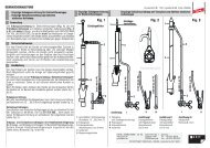
3. Phase comparison<br />
3.1 Test procedures for clear phase comparison<br />
The following test procedures must be<br />
carried out for clear phase comparison.<br />
Complete and correct sequence is required<br />
except the test must be interrupted.<br />
Note:<br />
Phase comparison is normally carried<br />
out at the joint of two networks/systems/<br />
system components/lines/etc. to be connected<br />
with each other. In the following<br />
these are termed "systems" (system 1<br />
and system 2).<br />
Test operation 1:<br />
Determination of the active state of the<br />
systems and functional test of the phase<br />
comparator<br />
With this test operation, it is indicated whether<br />
the test leads (phase conductors) of systems<br />
1 and 2 are live (active state) and the<br />
phase comparator DEHNcap/PC-LRM correctly<br />
functions.<br />
Switch on the device as described in Section<br />
2.2. In the following, compare all phases of<br />
system 1 with each other. Repeat the same<br />
procedure for system 2. The DEHNcap/PC-<br />
LRM must always show "out-of-phase condition"<br />
("≠") with the red LED showing permanent<br />
light.<br />
If this is not provided (e.g. the device shows<br />
"in-phase condition", or no indicator lights),<br />
there is a fault, e.g. a phase-to-earth fault,<br />
the line conductor is dead or the phase<br />
comparator is defect:<br />
® Interrupt the test operation!<br />
Test operation 2:<br />
Testing for in-phase condition<br />
Each of the line conductors (or phases)<br />
must be compared with each other. Plug the<br />
two test leads LA and LB in the appropriate<br />
test sockets of both systems (e.g. L1/system<br />
1 and L1/system 2). All line conductors<br />
(or phases) to be connected must be compared.<br />
The green LED showing permanent<br />
light means "in-phase condition" ("="). The<br />
red LED showing permanent light only once<br />
means "out-of-phase condition" ("≠") and<br />
both systems must not be connected with<br />
each other.<br />
3.2 The phase comparator DEHNcap/PC-<br />
LRM may only be used for three-phase<br />
systems.<br />
3.3 The systems may only be connected<br />
DEHN + SÖHNE GMBH + CO. KG. Hans-Dehn-Str. 1<br />
P.O. Box 1640<br />
92306 Neumarkt<br />
Germany<br />
www.dehn.de Tel: +49 9181 906-0<br />
export@dehn.de Fax: +49 9181 906-100 © COPYRIGHT 2003 DEHN + SÖHNE<br />
with each other when connectors/disconnectors<br />
are used which are also rated for<br />
switching on in out-of-phase states (of the<br />
connected systems).<br />
3.4 The phase comparator DEHNcap/PC-LRM<br />
is no synchronizer and must not be used<br />
for this purpose.<br />
4. Technical Data and Interface<br />
Characteristics<br />
4.1 Phase comparator DEHNcap/PC-LRM<br />
The phase comparator DEHNcap/PC-LRM<br />
may only be used for capacitive low-resistance<br />
LRM-systems in accordance with<br />
E DIN VDE 0682 Part 415.<br />
indication threshold: 5 V~<br />
input impedance: 2 MΩ<br />
nominal frequency: 50 Hz<br />
out-of-phase condition"≠": ≥ 60°<br />
battery: 9 V E block battery<br />
(IEC6LR61)<br />
4.2 Adapters<br />
In order to make sure the correct function of<br />
the phase comparator DEHNcap/PC-LRM,<br />
LRM adapters must be dimensioned in such<br />
a way that the interface voltage of 5 V AC<br />
comes up to 45% of the rated voltage (cont.<br />
operating voltage) of the system.<br />
5 . Maintenance and Upkeep<br />
5.1 The phase comparator DEHNcap/PC-LRM<br />
should be stored in an instrument case<br />
(<strong>Art</strong>.-No. 767 500). The instrument case<br />
protects the device effectively from damage<br />
due to dropping or impact.<br />
It is therefore recommended to take out the<br />
device from the instrument case only for<br />
battery replacement or inspection of the<br />
type label at the rear side of the device.<br />
Meaning of LED indicators<br />
Possible phase or operation states Indicators<br />
The device may only be placed or stored in<br />
locations where it is not exposed to high<br />
temperatures, moisture or heavy dust. The<br />
device must be clean and dry when it is<br />
used. No detergents or solvents may be<br />
used for cleaning the device. The device<br />
can be cleaned using a soft damp cloth.<br />
5.2 Battery replacement<br />
For battery replacement push the flat cover<br />
at the rear side of the device in the direction<br />
of the arrow. Remove the discharged battery<br />
and replace it by a new one. Now push<br />
back the flat cover in the opposite direction<br />
of the arrow until it is locked. Please take<br />
care that the discharged batteries are correctly<br />
recycled in line with environmental<br />
requirements.<br />
Suitable batteries:<br />
9 V E block battery (IEC 6LR61), nonleakage,<br />
e.g.<br />
– Energizer Alkaline No. 522<br />
– Varta Alkaline No. 4022<br />
– Duracell Alkali-Manganese MN 1604<br />
– Kodax XTRALIFE Alkali-Manganese K9V<br />
– Ultralife Lithium Power Cell U9VL<br />
5.3 Test Intervals according to German Regulation<br />
According to German regulation, coupling<br />
elements of capacitive voltage detecting<br />
systems have to be tested on keeping the<br />
limit values provided in the electrical rules.<br />
The temporal intervals for maintenance<br />
tests at coupling elements of capacitive<br />
voltage detecting systems depend on the<br />
application conditions, etc. However, according<br />
to German regulation, these test<br />
intervals must not exceed 6 years.<br />
6. Alterations, attachments, re-arrangements<br />
and tampering with the<br />
equipment are prohibited.<br />
7 . These instructions for use should be<br />
kept safely!<br />
ready for operation yellow LED: "POWER ON", permanent light<br />
in-phase condition green LED "=" showing permanent light<br />
out-of-phase condition red LED "≠" showing permanent light<br />
discharged batteries no indicator lights