12-2019
Fachzeitschrift für Hochfrequenz- und Mikrowellentechnik
Fachzeitschrift für Hochfrequenz- und Mikrowellentechnik

Sie wollen auch ein ePaper? Erhöhen Sie die Reichweite Ihrer Titel.
YUMPU macht aus Druck-PDFs automatisch weboptimierte ePaper, die Google liebt.
RF & Wireless<br />
5G/MIMO Design With Circuit/Antenna In-Situ<br />
Simulations<br />
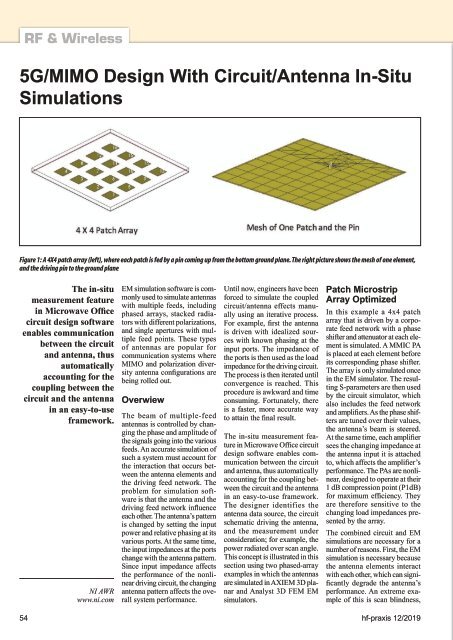
Figure 1: A 4X4 patch array (left), where each patch is fed by a pin coming up from the bottom ground plane. The right picture shows the mesh of one element,<br />
and the driving pin to the ground plane<br />
The in-situ<br />
measurement feature<br />
in Microwave Office<br />
circuit design software<br />
enables communication<br />
between the circuit<br />
and antenna, thus<br />
automatically<br />
accounting for the<br />
coupling between the<br />
circuit and the antenna<br />
in an easy-to-use<br />
framework.<br />
NI AWR<br />
www.ni.com<br />
EM simulation software is commonly<br />
used to simulate antennas<br />
with multiple feeds, including<br />
phased arrays, stacked radiators<br />
with different polarizations,<br />
and single apertures with multiple<br />
feed points. These types<br />
of antennas are popular for<br />
communication systems where<br />
MIMO and polarization diversity<br />
antenna configurations are<br />
being rolled out.<br />
Overwiew<br />
The beam of multiple-feed<br />
antennas is controlled by changing<br />
the phase and amplitude of<br />
the signals going into the various<br />
feeds. An accurate simulation of<br />
such a system must account for<br />
the interaction that occurs between<br />
the antenna elements and<br />
the driving feed network. The<br />
problem for simulation software<br />
is that the antenna and the<br />
driving feed network influence<br />
each other. The antenna’s pattern<br />
is changed by setting the input<br />
power and relative phasing at its<br />
various ports. At the same time,<br />
the input impedances at the ports<br />
change with the antenna pattern.<br />
Since input impedance affects<br />
the performance of the nonlinear<br />
driving circuit, the changing<br />
antenna pattern affects the overall<br />
system performance.<br />
Until now, engineers have been<br />
forced to simulate the coupled<br />
circuit/antenna effects manually<br />
using an iterative process.<br />
For example, first the antenna<br />
is driven with idealized sources<br />
with known phasing at the<br />
input ports. The impedance of<br />
the ports is then used as the load<br />
impedance for the driving circuit.<br />
The process is then iterated until<br />
convergence is reached. This<br />
procedure is awkward and time<br />
consuming. Fortunately, there<br />
is a faster, more accurate way<br />
to attain the final result.<br />
The in-situ measurement feature<br />
in Microwave Office circuit<br />
design software enables communication<br />
between the circuit<br />
and antenna, thus automatically<br />
accounting for the coupling between<br />
the circuit and the antenna<br />
in an easy-to-use framework.<br />
The designer identifies the<br />
antenna data source, the circuit<br />
schematic driving the antenna,<br />
and the measurement under<br />
consideration; for example, the<br />
power radiated over scan angle.<br />
This concept is illustrated in this<br />
section using two phased-array<br />
examples in which the antennas<br />
are simulated in AXIEM 3D planar<br />
and Analyst 3D FEM EM<br />
simulators.<br />
Patch Microstrip<br />
Array Optimized<br />
In this example a 4x4 patch<br />
array that is driven by a corporate<br />
feed network with a phase<br />
shifter and attenuator at each element<br />
is simulated. A MMIC PA<br />
is placed at each element before<br />
its corresponding phase shifter.<br />
The array is only simulated once<br />
in the EM simulator. The resulting<br />
S-parameters are then used<br />
by the circuit simulator, which<br />
also includes the feed network<br />
and amplifiers. As the phase shifters<br />
are tuned over their values,<br />
the antenna’s beam is steered.<br />
At the same time, each amplifier<br />
sees the changing impedance at<br />
the antenna input it is attached<br />
to, which affects the amplifier’s<br />
performance. The PAs are nonlinear,<br />
designed to operate at their<br />
1 dB compression point (P1dB)<br />
for maximum efficiency. They<br />
are therefore sensitive to the<br />
changing load impedances presented<br />
by the array.<br />
The combined circuit and EM<br />
simulations are necessary for a<br />
number of reasons. First, the EM<br />
simulation is necessary because<br />
the antenna elements interact<br />
with each other, which can significantly<br />
degrade the antenna’s<br />
performance. An extreme example<br />
of this is scan blindness,<br />
54 hf-praxis <strong>12</strong>/<strong>2019</strong>