SPR 80 SPR 120 SPR 165
SPR 80 SPR 120 SPR 165
SPR 80 SPR 120 SPR 165

Erfolgreiche ePaper selbst erstellen
Machen Sie aus Ihren PDF Publikationen ein blätterbares Flipbook mit unserer einzigartigen Google optimierten e-Paper Software.
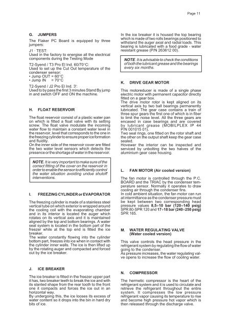
G. JUMPERS<br />
The Flaker PC Board is equipped by three<br />
jumpers:<br />
J1 · TEST:<br />
Used in the factory to energise all the electrical<br />
components during the Testing Mode<br />
T2-Syend / T3 Pro El Ind. 60/70°C:<br />
Used to set up the Cut Out temperature of the<br />
condenser sensor:<br />
• Jump OUT = 60°C<br />
• Jump IN = 70°C<br />
T2-Syend / J2 Pro El Ind. 3':<br />
Used to by pass the first 3 minutes Stand By jump<br />
in and switch OFF and ON the machine.<br />
H. FLOAT RESERVOIR<br />
The float reservoir consist of a plastic water pan<br />
on which is fitted a float valve with its setting<br />
screw. The float valve modulate the incoming<br />
water flow to maintain a constant water level in<br />
the reservoir, level that corresponds to the one in<br />
the freezing cylinder to ensure proper ice formation<br />
and fluidity.<br />
On the inner side of the reservoir cover are fitted<br />
the two water level sensors which detects the<br />
presence or the shortage of water in the reservoir.<br />
NOTE. It is very important to make sure of the<br />
correct fitting of the cover on the reservoir in<br />
order to enable the sensor to efficiently control<br />
the water situation avoiding undue shutoff<br />
interventions.<br />
I. FREEZING CYLINDER or EVAPORATOR<br />
The freezing cylinder is made of a stainless steel<br />
vertical tube on which exterior is wrapped around<br />
the cooling coil with the evaporating chamber<br />
and in its interior is located the auger which<br />
rotates on its vertical axis and it is maintained<br />
aligned by the top and bottom bearings. A water<br />
seal system is located in the bottom part of the<br />
freezer while at the top end is fitted the ice<br />
breaker.<br />
The water constantly flowing into the cylinder<br />
bottom part, freezes into ice when in contact with<br />
the cylinder inner walls. The ice is then lifted up<br />
by the rotating auger and compacted and forced<br />
out by the ice breaker.<br />
J. ICE BREAKER<br />
The ice breaker is fitted in the freezer upper part<br />
it has, two breaker teeth to break the ice and with<br />
its slanted shape from the rear tooth to the front<br />
one it compacts and forces the ice out in an<br />
horizontal way.<br />
By undergoing this, the ice looses its excess of<br />
water content so it drops into the bin in hard dry<br />
bits of ice.<br />
In the ice breaker it is housed the top bearing<br />
which is made of two rolls bearings positioned to<br />
withstand the auger axial and radial loads. This<br />
bearing is lubricated with a food grade - water<br />
resistant grease (P/N 263612 00).<br />
NOTE. It is advisable to check the conditions<br />
of both the lubricant grease and the bearings<br />
every six months.<br />
K. DRIVE GEAR MOTOR<br />
This motoreducer is made of a single phase<br />
electric motor with permanent capacitor directly<br />
fitted on a gear box.<br />
The drive motor rotor is kept aligned on its<br />
vertical axis by two ball bearings permanently<br />
lubricated. The gear case contains a train of<br />
three spur gears the first one of which is in fiber<br />
to limit the noise level. All the three gears are<br />
encased in case bearings and are covered<br />
by lubricant grease (MOBILPLEX IP 44<br />
P/N 001015 01).<br />
Two seal rings, one fitted on the rotor shaft and<br />
the other on the output shaft keep the gear case<br />
sealed.<br />
Hovewer the interior can be inspected and<br />
serviced by unbolting the two halves of the<br />
aluminium gear case housing.<br />
L. FAN MOTOR (Air cooled version)<br />
The fan motor is controlled through the P.C.<br />
BOARD and the TRIAC by the condenser temperature<br />
sensor. Normally it operates to draw<br />
cooling air through the condenser fins.<br />
In cold ambient situation, the fan motor can run<br />
at intermittance as the condenser pressure must<br />
be kept between two corresponding head<br />
pressure values 8,5÷10 bar (<strong>120</strong>÷140 psig)<br />
<strong>SPR</strong> <strong>80</strong>-<strong>SPR</strong> <strong>120</strong> and 17÷18 bar (240÷250 psig)<br />
<strong>SPR</strong> <strong>165</strong>.<br />
M. WATER REGULATING VALVE<br />
(Water cooled version)<br />
This valve controls the head pressure in the<br />
refrigerant system by regulating the flow of water<br />
going to the condenser.<br />
As pressure increases, the water regulating valve<br />
opens to increase the flow of cooling water.<br />
N. COMPRESSOR<br />
Page 11<br />
The hermetic compressor is the heart of the<br />
refrigerant system and it is used to circulate and<br />
retrieve the refrigerant throughout the entire<br />
system. It compresses the low pressure<br />
refrigerant vapor causing its temperature to rise<br />
and become high pressure hot vapor which is<br />
then released through the discharge valve.