SPR 80 SPR 120 SPR 165
SPR 80 SPR 120 SPR 165
SPR 80 SPR 120 SPR 165

Erfolgreiche ePaper selbst erstellen
Machen Sie aus Ihren PDF Publikationen ein blätterbares Flipbook mit unserer einzigartigen Google optimierten e-Paper Software.
Page 6<br />
PRINCIPLE OF OPERATION<br />
WATER CIRCUIT<br />
The water enter in the machine through the water<br />
inlet fitting which incorporates a strainer and it is<br />
located at the rear side of the cabinet and then it<br />
goes to the water reservoir flowing through a float<br />
valve.<br />
NOTE. The presence of the water in the float<br />
reservoir is detected by a system of two<br />
sensors which operates in conjunction with<br />
the P.C. Board. The two sensors use the<br />
water as a conductor to maintain a low voltage<br />
current flow between them signalling in this<br />
way to the P.C. Board the presence of the<br />
water in the reservoir. In case the water used<br />
is very soft (de-mineralized) or the float<br />
reservoir gets empty the current flow between<br />
the sensors become so weak or is no longer<br />
maintained that, as consequence, the P.C.<br />
Board shutoff the flaker operation with the<br />
simultaneous glowing of the YELLOW LED<br />
signalling “Shortage of water”.<br />
The float reservoir is positioned at the side of the<br />
freezing cylinder at such an height to be able to<br />
maintain a constant water level around the freezer<br />
auger.<br />
In fact, the water flows from the reservoir into the<br />
bottom inlet of the freezing cylinder to sorround<br />
the stainless steel auger which is vertically fitted<br />
in the center of the freezer.<br />
In the freezer the incoming water gets chilled into<br />
soft (slush) ice which is moved upward by the<br />
rotating action of the auger.<br />
The stainless steel auger that rotates counterclockwise<br />
within the freezer, is powered by a<br />
direct drive gear motor and carries the ice upward<br />
along the refrigerated freezer inner walls and by<br />
doing so the ice gets progressively thicker and<br />
harder.<br />
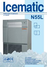
WATER INLET LINE<br />
FLOAT TANK<br />
FLOAT VALVE<br />
FREEZER<br />
FREEZER WATER<br />
FEED LINE<br />
ICE SPOUT<br />
The ice, being costantly lifted up, meet the teeth<br />
of the ice breaker which is fitted on the top end of<br />
the auger, where it gets compacted, cracked and<br />
forced to change from vertical into horizontal<br />
motion to be discharged out, through the ice<br />
spout and chute, into the storage bin.<br />
By running the ice maker, i.e. by putting the unit<br />
under power, starts the automatic and continuous<br />
icemaking process which would not stop until the<br />
ice storage bin gets filled-up to the level of the<br />
control “eyes” located on the sides of the ice<br />
chute.<br />
As the ice level raises to interrupt the light beam<br />
running between the two infrared lamps, the unit<br />
stops after ten seconds, with the simulteneous<br />
glowing of the YELLOW LED signalling the<br />
“Full Bin” situation.<br />
NOTE. The interruption of the light beam<br />
between the two light sensors is immediately<br />
signalled by the blinking of the bin full<br />
YELLOW LED located on the front of the<br />
P.C. Board.<br />
After about 6" of steady interruption of the<br />
light beam the unit stops and the “Full Bin”<br />
YELLOW LED glows.<br />
The six seconds of delay prevent the unit<br />
from stopping for any undue reason like the<br />
momentarily interruption of the light beam<br />
caused by the flakes that slides along the ice<br />
spout before dropping into the bin.<br />
As some ice gets scooped out from the storage<br />
bin, the light beam between the two sensors<br />
resumes; six seconds later the ice machine<br />
restarts the ice making process (going always<br />
through the 3' stand by) and the YELLOW LED<br />
goes off.<br />
REFRIGERANT CIRCUIT<br />
The hot gas refrigerant discharged out from the<br />
compressor reaches the condenser where, being<br />
cooled down, condenses into liquid.<br />
Flowing into the liquid line it passes through the<br />
drier filter, then it goes all the way through the<br />
capillary tube where it looses some of its pressure<br />
so that its pressure and temperature are lowered.<br />
Next, the refrigerant enters into the evaporator<br />
coil wrapped around the freezer inner tube.<br />
The water being constantly fed at the interior of<br />
the freezer inner tube, exchange heat with the<br />
refrigerant circulating into the evaporator coil,<br />
this cause the refrigerant to boil-off and evaporate,<br />
thereby it changes from liquid into vapor.<br />
The vapor refrigerant then passes through the<br />
suction accumulator and through the suction line<br />
where the refrigerant exchanges heat with the<br />
one flowing into the capillary tube (warmer)<br />
before being sucked into the compressor to be<br />
recirculated.<br />
The refrigerant head pressure is kept between<br />
two pre-set values 8,5÷10 bar (<strong>120</strong>÷140 psig)<br />
<strong>SPR</strong> <strong>80</strong>-<strong>SPR</strong> <strong>120</strong> and 17÷18 bar (240÷250<br />
psig) <strong>SPR</strong> <strong>165</strong> by the condenser temperature<br />
sensor which has its probe located within the<br />
condenser fins - in air cooled versions.