SPR 80 SPR 120 SPR 165
SPR 80 SPR 120 SPR 165
SPR 80 SPR 120 SPR 165

Sie wollen auch ein ePaper? Erhöhen Sie die Reichweite Ihrer Titel.
YUMPU macht aus Druck-PDFs automatisch weboptimierte ePaper, die Google liebt.
SERVICE MANUAL<br />
BEDIENUNGSANLEITUNGNG<br />
<strong>SPR</strong> <strong>80</strong><br />
<strong>SPR</strong> <strong>120</strong><br />
<strong>SPR</strong> <strong>165</strong><br />
R 134 A / R 404 A<br />
Electronic flakers<br />
Elektronische<br />
Flockeneisbereiter<br />
090091.04 REV. 06/03
TABLE OF CONTENTS PAGE INHALTSVERZEICHNIS SEITE<br />
GENERAL INFORMATION AND INSTALLATION 1 ALLGEMEINES UND INSTALLATION 16<br />
Introduction 1 Einführung 16<br />
Unpacking and inspection 1 Anspacken und Inspektion 16<br />
Location and levelling 1 Maschinenplatz und lotgerechte Austellung 16<br />
Electrical connections 1 Elektrische Anschlüße 16<br />
Water supply and drain connections 2 Wasserversorgung und Abflußleitungen 17<br />
Final check list 2 Schlußkontrollen 17<br />
Installation practice 3 Installation 18<br />
OPERATING INSTRUCTIONS 4 BEDIENUNGSANLEITUNG 19<br />
Start-up 4 Inbetriebnahme 19<br />
Operation checks upon the unit start-up 4 Ueberprüfung im Betrieb 19<br />
PRINCIPLE OF OPERATION 6 FUNKTION<strong>SPR</strong>INZIP 21<br />
Water circuit 6 Wasserkreislauf 21<br />
Refrigerant circuit 6 Kuehlmittelkreislauf 21<br />
Mechanical System 7 Getriebeeinheit 22<br />
Operating characteristics 8 Betriebseigenschaften 22<br />
Components description 9 Komponentenbeschreibung 24<br />
Service diagnosis 12 Funktionsfehler/Schadenanalyse 27<br />
MAINTENANCE AND CLEANING INSTRUCTIONS 14 WARTUNG UND REINIGUNGSANLEITUNG 29<br />
General 14 Voraussetzung 29<br />
Icemaker 14 Reinigung des eisbereiters 29<br />
Cleaning instructions of water system 14 Reinigen des wasserkreislaufes 30<br />
a
<strong>SPR</strong> <strong>80</strong><br />
E<br />
F G<br />
H<br />
I<br />
L<br />
M<br />
<strong>SPR</strong> <strong>120</strong> - <strong>SPR</strong> <strong>165</strong><br />
I<br />
1<br />
B<br />
1<br />
2<br />
3<br />
4<br />
5<br />
1<br />
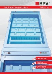
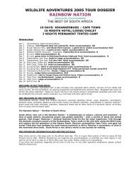
( 1 ) WATER OUTLET BIN<br />
WASSERABLAUF ZELLE<br />
( 2 ) WATER INLET - WATER COOLED<br />
WASSERZUFUHR - WASSERGEKÜHLTE<br />
( 3 ) WATER OUTLET - WATER COOLED<br />
WASSERABLAUF - WASSERGEKÜHLTE<br />
( 4 ) WATER INLET<br />
WASSERZUFUHR<br />
( 5 ) CORD SET<br />
KABEL<br />
<strong>SPR</strong> <strong>80</strong> <strong>SPR</strong> <strong>120</strong> <strong>SPR</strong> <strong>165</strong><br />
A 626 590 590<br />
B 529 920 920<br />
C 797 785 785<br />
D 135 135 135<br />
E <strong>80</strong> 285 285<br />
F 70 185 185<br />
G 58 130 130<br />
H 57 55 55<br />
I 140 200 200<br />
L 243 2<strong>80</strong> 2<strong>80</strong><br />
M 300
<strong>SPR</strong> <strong>80</strong> <strong>SPR</strong> <strong>80</strong> W <strong>SPR</strong> <strong>120</strong> <strong>SPR</strong> <strong>120</strong> W <strong>SPR</strong> <strong>165</strong> <strong>SPR</strong> <strong>165</strong> W<br />
Electric voltage 230/50/1 230/50/1 230/50/1<br />
Normale Netzspannung -10 ÷ +6% -10 ÷ +6% -10 ÷ +6%<br />
Condensation Air Water Air Water Air Water<br />
Kühlung Luft Wasser Luft Wasser Luft Wasser<br />
Bin Capacity (kg)<br />
Speiker Kapacitt (kg 25 55 60<br />
Net weight (kg)<br />
Netto Gewicht (kg) 51 52 67 69 71 73<br />
Compressor power HP<br />
Kompressorleistung PS 1/4 3/8 3/4<br />
Running amps<br />
Ampere 2,2 3,2 4<br />
Start amps<br />
Start Ampere 11 17 20<br />
Power (Watts)<br />
Leistung (Watt) 330 500 760<br />
Power cons. in 24 hrs (Kwh)<br />
Stromverbrauch in 24 std (Kwh) 7,5 11 17<br />
Wire size (mm 2 )<br />
Kabelanzahl (mm 2 ) 3 x 1,5 3 x 1,5 3 x 1<br />
Water consumption (lt/hr)<br />
Wasserverbrauch (lt/std) 2,9 10* 5 20* 8,4 35*<br />
Refrig. charge R 404 a (gr)<br />
Kühlmittel Füll. R 404 a (gr) – – – – 540 410<br />
Refrig. charge R 134 a (gr)<br />
Kühlmittel Füll. R 134 a (gr) 310 310 440 3<strong>80</strong> – –<br />
Refrigerant metering device Capillary tube Capillary tube Capillary tube<br />
Kältemittel-Expansionssystem Kapillarrohr Kapillarrohr Kapillarrohr<br />
* Water - Wasser: 15°C<br />
TECHNICAL SPECIFICATIONS - TECHNISCHE ANGABEN<br />
OPERATING PRESSURES - BETRIEBSDRÜCKE<br />
Discharge pressure - Hochdruckbereich<br />
<strong>SPR</strong> <strong>80</strong> <strong>SPR</strong> <strong>120</strong> <strong>SPR</strong> <strong>165</strong><br />
Air cooled (21°C)<br />
Luftgekühlt (21°C) 8,5 ÷ 10 bar 8 ÷10 bar 17 ÷ 18 bar<br />
Water cooled<br />
Wassergekühlt 9,5 bar 9,5 bar 17 bar<br />
Suction pressure - Niederdruck<br />
0,5 bar 0,7 ÷ 0,9 bar 2,4 ÷ 2,5 bar<br />
c
d<br />
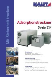
( 1) P.C. BOARD<br />
ELEKTRONISCHE STEUERKARTE<br />
( 2) FUSE<br />
SCHMELZSICHERUNG<br />
( 3) POWER ON<br />
UNTER SPANNUNG<br />
( 4) BIN FULL<br />
SPEICHER VOLL<br />
( 5) SHORTAGE OF WATER<br />
WASSERMANGEL<br />
WIRING DIAGRAM - SCHALTBILD<br />
Air and water cooled - Luft und Wasserkühlung<br />
<strong>SPR</strong> <strong>80</strong> - <strong>SPR</strong> <strong>120</strong> - <strong>SPR</strong> <strong>165</strong><br />
220-240/50/1<br />
( 6) TOO HIGH COND. TEMP.<br />
ZU HOHE KONDENSATIONSTEMP.<br />
( 7) GEAR MOTOR WRONG ROTATION<br />
FALSCHE DREHUNGSRICHTUNG GETRIEBEMOTOR<br />
( 9) TERMINAL BOARD<br />
ANSCHLUSSKASTEN<br />
(10) AUTOTRANSFORMER<br />
AUTOTRAFO<br />
(11) SENSORS<br />
FÜHLER<br />
* JUST FOR AIR COOLED UNIT / NUR FÜR LUFTGEKÜHLTE GERÄTE<br />
(12) WATER LEVEL<br />
WASSERNIVEAU<br />
(13) WRONG DIRECTION<br />
FALSCHE DREHUNGSRICHTUNG<br />
(14) CONDENSER TEMPERATURE<br />
KONDENSATOR-TEMPERATUR<br />
(15) EVAPORATOR TEMPERATURE<br />
VERDAMPFER-TEMPERATUR<br />
(16) ICE LEVEL SENSOR<br />
OPTISCHE EIS NIVEAU KONTROLLE<br />
USED ONLY UNIT 240 V / NUR FÜR GERÄTE 240 V<br />
**<br />
3<br />
(17) COMPRESSOR<br />
KOMPRESSOR<br />
(18) GEAR MOTOR<br />
GETRIEBEMOTOR<br />
(19) FAN MOTOR<br />
LÜFTER MOTOR
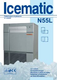
ICE PRODUCED PER 24 HRS.<br />
EISWÜRFEL PRODUKTION IN 24 STD.<br />
ICE PRODUCED PER 24 HRS.<br />
EISWÜRFEL PRODUKTION IN 24 STD.<br />
ICE PRODUCED PER 24 HRS.<br />
EISWÜRFEL PRODUKTION IN 24 STD.<br />
Kg.<br />
<strong>120</strong><br />
115<br />
110<br />
105<br />
100<br />
95<br />
90<br />
85<br />
Ice making capacity - Eisproduktionskapazität<br />
AIR COOLED MODELS - LUFTKÜHLUNG<br />
Kg.<br />
°C<br />
70<br />
10<br />
68<br />
66<br />
64<br />
62<br />
60<br />
58<br />
21<br />
56<br />
54<br />
32<br />
52<br />
50<br />
48<br />
46<br />
38<br />
44<br />
32 27 21 15 10 °C<br />
90 <strong>80</strong> 70 60 50 °F<br />
WATER TEMPERATURE - WASSERTEMPERATUR<br />
AIR COOLED MODELS - LUFTKÜHLUNG<br />
°C<br />
10<br />
21<br />
32<br />
38<br />
<strong>SPR</strong> <strong>80</strong><br />
AMBIENT TEMPERATURE<br />
RAUMTEMPERATUR<br />
<strong>SPR</strong> <strong>120</strong><br />
AMBIENT TEMPERATURE<br />
RAUMTEMPERATUR<br />
ICE PRODUCED PER 24 HRS.<br />
EISWÜRFEL PRODUKTION IN 24 STD.<br />
ICE PRODUCED PER 24 HRS.<br />
EISWÜRFEL PRODUKTION IN 24 STD.<br />
WATER COOLED MODELS - WASSERKÜHLUNG<br />
Kg.<br />
74<br />
°C<br />
72<br />
70<br />
68<br />
10<br />
66<br />
64<br />
62<br />
21<br />
60<br />
32<br />
58<br />
56<br />
54<br />
52<br />
50<br />
38<br />
48<br />
32 27 21 15 10 °C<br />
90 <strong>80</strong> 70 60 50 °F<br />
WATER TEMPERATURE - WASSERTEMPERATUR<br />
WATER COOLED MODELS - WASSERKÜHLUNG<br />
Kg.<br />
°C<br />
<strong>120</strong><br />
10<br />
<strong>80</strong><br />
<strong>80</strong><br />
32 27 21 15 10 °C<br />
32 27 21 15 10 °C<br />
90 <strong>80</strong> 70 60 50<br />
WATER TEMPERATURE - WASSERTEMPERATUR<br />
°F<br />
90 <strong>80</strong> 70 60 50 °F<br />
WATER TEMPERATURE - WASSERTEMPERATUR<br />
Kg.<br />
220<br />
200<br />
1<strong>80</strong><br />
160<br />
140<br />
<strong>120</strong><br />
AIR COOLED MODELS - LUFTKÜHLUNG<br />
100<br />
32 27 21 15 10<br />
90 <strong>80</strong> 70 60 50<br />
WATER TEMPERATURE - WASSERTEMPERATUR<br />
°C<br />
10<br />
21<br />
32<br />
38<br />
°C<br />
°F<br />
<strong>SPR</strong> <strong>165</strong><br />
AMBIENT TEMPERATURE<br />
RAUMTEMPERATUR<br />
ICE PRODUCED PER 24 HRS.<br />
EISWÜRFEL PRODUKTION IN 24 STD.<br />
115<br />
110<br />
105<br />
100<br />
95<br />
90<br />
85<br />
WATER COOLED MODELS - WASSERKÜHLUNG<br />
Kg.<br />
200<br />
190<br />
1<strong>80</strong><br />
170<br />
160<br />
150<br />
140<br />
32 27 21 15 10 °C<br />
90 <strong>80</strong> 70 60 50 °F<br />
WATER TEMPERATURE - WASSERTEMPERATUR<br />
21<br />
32<br />
38<br />
DE 10 A 38°C<br />
e<br />
AMBIENT TEMPERATURE<br />
RAUMTEMPERATUR<br />
AMBIENT TEMPERATURE<br />
RAUMTEMPERATUR<br />
AMBIENT TEMPERATURE<br />
RAUMTEMPERATUR
f<br />
( A ) SENSORS<br />
FÜHLER<br />
( B ) MIN. WATER LEVEL<br />
MIN. WASSERNWEAU<br />
( C ) GEAR MOTOR ROTATION<br />
GETRIEBEMOTOR-DREHUNG<br />
( D ) COND. TEMPERATURE<br />
KONDENSATOR-TEMPERATUR<br />
( E ) EVAP. TEMPERATURE<br />
VERDAMPFER-TEMPERATUR<br />
( F ) ICE LEVEL CONTROL<br />
EIS NIVEAUKONTROLLE<br />
( G ) COMPRESSOR<br />
COMPRESSOR<br />
( I ) MICRO PROCESSOR<br />
MIKROPROZESSOR<br />
( L ) LINE<br />
LINIE<br />
( M) TRANSFORMER<br />
TRANSFORMATOR<br />
( N ) NEUTRE<br />
NEUTRAL<br />
( O ) RELAY<br />
RELAIS<br />
( P ) TRIAC<br />
TRIAC-POTENTIOMETER<br />
( Q ) CONTACTOR COIL<br />
CONTACTOR SPULE<br />
( R ) GEAR MOTOR<br />
GETRIEBEMOTOR<br />
( S ) FAN MOTOR<br />
LÜFTER<br />
( T ) P.C. BOARD<br />
ELEKTRONISCHE STEUERKARTE
GENERAL INFORMATION<br />
AND INSTALLATION<br />
A. INTRODUCTION<br />
This manual provides the specifications and the<br />
step-by-step procedures for the installation, startup<br />
and operation, maintenance and cleaning for<br />
the SIMAG <strong>SPR</strong> <strong>80</strong>, <strong>SPR</strong> <strong>120</strong> and <strong>SPR</strong> <strong>165</strong><br />
Icemakers.<br />
The Electronic Flakers are quality designed,<br />
engineered and manufactured.<br />
Their ice making systems are thoroughly tested<br />
providing the utmost in flexibility to fit the needs<br />
of a particular user.<br />
NOTE. To retain the safety and performance<br />
built into this icemaker, it is important that<br />
installation and maintenance be conducted<br />
in the manner outlined in this manual.<br />
B. UNPACKING AND INSPECTION<br />
1. Call your authorized SIMAG Distributor or<br />
Dealer for proper installation.<br />
2. Visually inspect the exterior of the packing<br />
and skid. Any severe damage noted should be<br />
reported to the delivering carrier and a concealed<br />
damage claim form filled in subjet to inspection of<br />
the contents with the carrier’s representative<br />
present.<br />
NOTE. If there are doubts, on the delivery<br />
note register the following caption:<br />
ACCEPTED WITH RESERVATION.<br />
3. a) Cut and remove the plastic strip securing<br />
the carton box to the skid.<br />
b) Remove the packing nails securing the<br />
carton box to the skid.<br />
c) Cut open the top of the carton and remove<br />
the protection sheet.<br />
d) Pull out the polystyre posts from the<br />
corners and then remove the carton.<br />
4. Remove the front panel of the unit and<br />
inspect for any concealed damage. Notify carrier<br />
of your claim for the concealed damage as stated<br />
in step 2 above.<br />
5. Remove all internal support packing and<br />
masking tape.<br />
6. Check that refrigerant lines do not rub<br />
against or touch other lines or surfaces, and that<br />
the fan blades move freely.<br />
7. Check that the compressor fits snugly onto<br />
all its mounting pads.<br />
8. See data plate on the rear side of the unit<br />
and check that local main voltage corresponds<br />
with the voltage specified on it.<br />
CAUTION. Incorrect voltage supplied to<br />
the icemaker will void your parts<br />
replacement program.<br />
9. Remove the manufacturer’s registration card<br />
from the inside of the User Manual and fill-in all<br />
parts including: Model and Serial Number taken<br />
from the data plate.<br />
Forward the completed self-addressed<br />
registration card to SIMAG factory.<br />
C. LOCATION AND LEVELLING<br />
WARNING. This Modular Flaker and<br />
Superflaker is designed for indoor<br />
installation only. Extended periods of<br />
operation at temperature exceeding the<br />
following limitations will constitute misuse<br />
under the terms of the SIMAG<br />
Manufacturer’s Limited Warranty resulting<br />
in LOSS of warranty coverage.<br />
1. Position the storage bin in the selected<br />
permanent location.<br />
Criteria for selection of location include:<br />
a) Minimum room temperature 10°C (50°F)<br />
and maximum room temperature 40°C (100°F).<br />
b) Water inlet temperatures: minimum 5°C<br />
(40°F) and maximum 40°C (100°F).<br />
c) Well ventilated location for air cooled<br />
models (clean the air cooled condenser at frequent<br />
intervals).<br />
d) Service access: adequate space must be<br />
left for all service connections through the rear of<br />
the ice maker. A minimum clearance of 15 cm (6")<br />
must be left at the sides of the unit for routing<br />
cooling air drawn into and exhausted out of the<br />
compartment to maintain proper condensing<br />
operation of air cooled models.<br />
2. Level the icemaker in both the left to right<br />
and front to rear directions by means of the<br />
adjustable legs.<br />
D. ELECTRICAL CONNECTIONS<br />
Page 1<br />
See data plate for current requirements to<br />
determine wire size to be used for electrical<br />
connections. All SIMAG icemakers require a<br />
solid earth wire.<br />
All SIMAG ice machines are supplied from the<br />
factory completely pre-wired and require only<br />
electrical power connections to the wire cord<br />
provided at the rear of the unit.
Page 2<br />
Make sure that the ice machine is connected to its<br />
own circuit and individually fused (see data plate<br />
for fuse size).<br />
The maximum allowable voltage variation should<br />
not exceed -10% and +10% of the data plate<br />
rating. Low voltage can cause faulty functioning<br />
and may be responsible for serious damage to<br />
the overload switch and motor windings.<br />
NOTE. All external wiring should conform to<br />
national, state and local standards and<br />
regulations.<br />
Check voltage on the line and the ice maker’s<br />
data plate before connecting the unit.<br />
E. WATER SUPPLY AND DRAIN<br />
CONNECTIONS<br />
GENERAL<br />
When choosing the water supply for the ice flaker<br />
consideration should be given to:<br />
a) Length of run<br />
b) Water clarity and purity<br />
c) Adequate water supply pressure<br />
Since water is the most important single ingredient<br />
in producting ice you cannot emphasize too much<br />
the three items listed above.<br />
Low water pressure, below 1 bar may cause<br />
malfunction of the ice maker unit.<br />
Water containing excessive minerals will tend to<br />
produce scale build-up on the interior parts of the<br />
water system while too soft water (with too lo<br />
contents of mineral salts), will produce a very<br />
hard flaker ice.<br />
WARNING. The use of de-mineralized<br />
water (water with no salt content) having<br />
an electrical conductivity lower than 30 μs,<br />
will cause the ability of the water sensors<br />
to vanish with the consequent CUT-OUT<br />
of the flaker operations.<br />
WATER SUPPLY<br />
Connect the 3/4" GAS male of the water inlet<br />
fitting, using the food grade flexible tubing supplied<br />
with the machine, to the cold water supply line<br />
with regular plumbing fitting and a shut-off valve<br />
installed in an accessible position between the<br />
water supply line and the unit.<br />
If water contains a high level of impurities, it is<br />
advisable to consider the installation of an<br />
appropriate water filter or conditioner.<br />
WATER SUPPLY - WATER COOLED MODELS<br />
The water cooled versions of SIMAG Ice Makers<br />
require two separate inlet water supplies, one for<br />
the water making the flaker ice and the other for<br />
the water cooled condenser.<br />
Connect the 3/4" GAS male fitting of the water<br />
inlet, using the flexible tubing supplied with the<br />
unit, to the cold water supply line with regular<br />
plumbing fitting and a shut-off valve installed in<br />
an accessible position between the water supply<br />
line and the unit.<br />
WATER DRAIN<br />
Connect the drain fitting with the plastic tube<br />
supplied to an open trapped and vented drain.<br />
When the drain is a long run, allow 3 cm pitch per<br />
meter (1/4" pitch per foot).<br />
The ideal drain receptacle is a trapped and<br />
vented floor drain.<br />
WATER DRAIN - WATER COOLED MODELS<br />
Connect the 3/4" GAS male fitting of the<br />
condenserwater drain, utilizing the flexible tubing<br />
supplied, to the open trapped and vented drain.<br />
This additional drain line must not interconnect to<br />
any other of the units drains.<br />
NOTE. The water supply and the water drain<br />
must be installed to conform with the local<br />
code. In some case a licensed plumber and/<br />
or a plumbing permit is required.<br />
F. FINAL CHECK LIST<br />
1. Is the unit in a room where ambient<br />
temperatures are within a minimum of 10°C<br />
(50°F) even in winter months?<br />
2. Is there at least a 15 cm (6") clearance<br />
around the unit for proper air circulation?<br />
3. Is the unit level? (IMPORTANT)<br />
4. Have all the electrical and plumbing<br />
connections been made, and is the water supply<br />
shut-off valve open?<br />
5. Has the voltage been tested and checked<br />
against the data plate rating?<br />
6. Has the water supply pressure been<br />
checked to ensure a water pressure of at least<br />
1 bar (14 psi).<br />
7. Have the bolts holding the compressor down<br />
been checked to ensure that the compressor is<br />
snugly fitted onto the mounting pads?<br />
8. Check all refrigerant lines and conduit lines<br />
to guard against vibrations and possible failure.<br />
9. Have the bin liner and cabinet been wiped<br />
clean?<br />
10. Has the owner/user been given the User<br />
Manual and been instructed on the importance of<br />
periodic maintenance checks?
11. Has the Manufacturer’s registration card<br />
been filled in properly? Check for correct model<br />
and serial number against the serial plate and<br />
mail the registration card to the factory.<br />
G. INSTALLATION PRACTICE<br />
12. Has the owner been given the name and the<br />
phone number of the authorized SIMAG Service<br />
Agency serving him?<br />
1. Hand shut-off valve<br />
2. Water filter<br />
3. Water supply line<br />
(flexible hose)<br />
4. 3/4" GAS male fitting<br />
5. Power line<br />
6. Main switch<br />
7. Drain fitting<br />
8. Vented drain<br />
9. Open tapped vented<br />
drain<br />
Page 3<br />
WARNING. This icemaker is not designed for outdoor installation and will not function in<br />
ambient temperatures below 10°C (50°F) or above 40°C (100°F).<br />
This icemaker will malfunction with water temperatures below 5°C (40°F) or above 40°C<br />
(100°F).
Page 4<br />
OPERATING<br />
INSTRUCTIONS<br />
START UP<br />
After having correctly installed the ice maker and<br />
completed the plumbing and electrical<br />
connections, perform the following “Start-up” procedure.<br />
A. Open the water supply line shutoff valve<br />
and put the unit under electrical power by moving<br />
the main switch, on the power supply line, to the<br />
ON position.<br />
The first LED - GREEN - will glow to signal that<br />
unit is under power.<br />
NOTE. Every time the unit is put under power,<br />
after being kept for sometime in shut-off<br />
conditions (electrically disconnected) the RED<br />
LED will blink for 3 minutes after which the<br />
unit will start up with the immediate operation<br />
of the gear motor assembly and, after few<br />
seconds, of the compressor assy (Fig.1).<br />
B. Elapsed the 3 minutes - stand by period - the<br />
unit starts operating with the activation in<br />
sequence of the following assemblies:<br />
GEAR MOTOR/S<br />
COMPRESSOR<br />
FAN MOTOR/S (if unit is an air cooled version)<br />
kept under control by the condenser temperature<br />
sensor which has its probe within the condenser<br />
fins (Fig.2).<br />
C. Elapsed 2 or 3 minutes from the compressor<br />
start up, observe that flaker ice begins dropping<br />
off the ice spout to fall through the ice chute into<br />
the storage bin.<br />
NOTE. The first ice bits that drop into the ice<br />
storage bin are not so hard as the evaporating<br />
temperature has not yet reached the correct<br />
operating value. It is necessary to allow the<br />
ice - just made - to cure itself and wait for<br />
about ten minutes for the evaporating temperature<br />
to reach the correct value so to make<br />
more hard bits of ice.<br />
NOTE. If, after ten minutes from the<br />
compressor start-up, the evaporating temperature<br />
has not dropped down to a value<br />
lower than -1°C (30°F) due to an insufficient<br />
quantity of refrigerant in the system, the<br />
evaporating temperature sensor detects such<br />
an abnormal situation and stops consequently<br />
the unit operation.<br />
In this circustance, the 5th warning YELLOW<br />
LED will blink (Fig.3).<br />
The machine will remain in OFF mode for<br />
one hour then it will restart automatically.<br />
In case the unit trips OFF again in alarm for<br />
3 times in 3 hours, the machine SHUTS OFF<br />
DEFINITIVELY.<br />
After having diagnosed and eliminated the<br />
cause of the poor evaporating temperature<br />
(insufficient refrigerant in the system or<br />
excessive condensing temperature) it is<br />
necessary to unplug and plug in again to<br />
restart the machine.<br />
The unit, before resuming the total operation,<br />
will go through the usual 3 minutes<br />
STAND-BY period.<br />
OPERATION CHECKS UPON THE UNIT<br />
START UP<br />
D. Remove front service panel and, if<br />
necessary, install the refrigerant service gauges<br />
on the corresponding Schräder valves to check<br />
both the HI and LO refrigerant pressures.<br />
NOTE. On air cooled models, the condenser<br />
temperature sensor, which is located within<br />
the condenser fins, keeps the head<br />
(condensing) pressure between preset<br />
values.<br />
In the event of condenser clogged - such to<br />
prevent the proper flow of the cooling air - or,<br />
in case the fan motor is out of operation, the<br />
condenser temperature rises and when it<br />
reaches 70°C (160°F) for air cooled version -<br />
and 62°C (145°F) - for water cooled version -<br />
the condenser temperature sensor shuts-off<br />
the ice maker with the consequent light-up of<br />
the RED WARNING LIGHT (Fig.4).<br />
The machine will remain in OFF mode for<br />
one hour then it will restart automatically.<br />
In case the unit trips OFF again in alarm for<br />
3 times in 3 hours, the machine SHUTS OFF<br />
DEFINITIVELY.<br />
After having diagnosed the reason of the<br />
temperature rise and removed its cause, it is<br />
necessary to proceed as per the previous<br />
“NOTE” to start up again the operation of the<br />
ice maker.
E. Check for the correct CUT-OUT and CUT-<br />
IN of the float reservoir water level sensors by<br />
first shutting closed the water shutoff valve on<br />
the water supply line.<br />
This will cause a gradual decrease of the water<br />
level in the float reservoir and as soon as the<br />
level gets below the sensors, the flaker stops to<br />
operate and the YELLOW warning LED will<br />
glow to signal the shortage of water (Fig.5).<br />
NOTE. The water level sensor detects the<br />
presence of sufficient water in the float<br />
reservoir and confirms it to the micro<br />
processor by maintaining a low voltage<br />
current flow between the two sensors using<br />
the water as conductor.<br />
WARNING. The use of de-mineralized<br />
water (water with no salt content) having<br />
an electrical conductivity lower than 30<br />
μS, will cause the ability of the water<br />
sensors to vanish with the consequent<br />
CUT-OUT of the flaker operations and the<br />
glowing of the YELLOW LED of shortage<br />
of water, even though that the water is<br />
indeed in the reservoir.<br />
After this open the water supply line shutoff valve<br />
to fill up again the float reservoir, the YELLOW<br />
LED goes off while the RED LED starts blinking.<br />
After 3 minutes the unit resumes its total operation<br />
with the immediate start-up of the gear motor<br />
and, few seconds later, of the compressor.<br />
F. Check for the correct operation of the<br />
electronic eye (one per each ice chute on model<br />
SPN <strong>120</strong>5) for the ice bin level control, by placing<br />
one hand between the sensing “eyes” located in<br />
the ice spout, to interrupt the light beam.<br />
Page 5<br />
This interruption will cause an immediate blinking<br />
of the bin full YELLOW LED located on the front<br />
of the P.C. Board and after about 10 seconds<br />
causes the shutoff of the unit with the<br />
simultaneous lighting of the YELLOW LED<br />
signalling the full bin situation (Fig.6).<br />
Allow the resumption of the light beam previously<br />
interrupted and after about 6 seconds the flaker<br />
will resume - through the 3 minutes STAND-BY<br />
period - the ice making process with the<br />
extinguishing of the YELLOW LED.<br />
NOTE. The ICE LEVEL CONTROL<br />
(INFRARED SYSTEM) is independent of<br />
the temperature however, the reliability of its<br />
detection can be affected by external light<br />
radiations or by any sort of dirt and scale<br />
sediment which may deposit directly on the<br />
light source and on the receiver.<br />
To prevent any possible ice maker<br />
malfunction, due to negative affection of the<br />
light detector, it is advisable to locate the unit<br />
where it is not reached by any direct light<br />
beam or light radiation, also it is<br />
recommended to keep the bin door constantly<br />
closed and to follow the instructions for the<br />
periodical cleaning of the light sensor<br />
elements as detailed in the MAINTENANCE<br />
AND CLEANING PROCEDURES.<br />
G. If previously installed, remove the refrigerant<br />
service gauges and re-fit the unit service panels<br />
previously removed.<br />
H. Instruct the owner/user on the general<br />
operation of the ice machine and about the<br />
cleaning and care it requires.
Page 6<br />
PRINCIPLE OF OPERATION<br />
WATER CIRCUIT<br />
The water enter in the machine through the water<br />
inlet fitting which incorporates a strainer and it is<br />
located at the rear side of the cabinet and then it<br />
goes to the water reservoir flowing through a float<br />
valve.<br />
NOTE. The presence of the water in the float<br />
reservoir is detected by a system of two<br />
sensors which operates in conjunction with<br />
the P.C. Board. The two sensors use the<br />
water as a conductor to maintain a low voltage<br />
current flow between them signalling in this<br />
way to the P.C. Board the presence of the<br />
water in the reservoir. In case the water used<br />
is very soft (de-mineralized) or the float<br />
reservoir gets empty the current flow between<br />
the sensors become so weak or is no longer<br />
maintained that, as consequence, the P.C.<br />
Board shutoff the flaker operation with the<br />
simultaneous glowing of the YELLOW LED<br />
signalling “Shortage of water”.<br />
The float reservoir is positioned at the side of the<br />
freezing cylinder at such an height to be able to<br />
maintain a constant water level around the freezer<br />
auger.<br />
In fact, the water flows from the reservoir into the<br />
bottom inlet of the freezing cylinder to sorround<br />
the stainless steel auger which is vertically fitted<br />
in the center of the freezer.<br />
In the freezer the incoming water gets chilled into<br />
soft (slush) ice which is moved upward by the<br />
rotating action of the auger.<br />
The stainless steel auger that rotates counterclockwise<br />
within the freezer, is powered by a<br />
direct drive gear motor and carries the ice upward<br />
along the refrigerated freezer inner walls and by<br />
doing so the ice gets progressively thicker and<br />
harder.<br />
WATER INLET LINE<br />
FLOAT TANK<br />
FLOAT VALVE<br />
FREEZER<br />
FREEZER WATER<br />
FEED LINE<br />
ICE SPOUT<br />
The ice, being costantly lifted up, meet the teeth<br />
of the ice breaker which is fitted on the top end of<br />
the auger, where it gets compacted, cracked and<br />
forced to change from vertical into horizontal<br />
motion to be discharged out, through the ice<br />
spout and chute, into the storage bin.<br />
By running the ice maker, i.e. by putting the unit<br />
under power, starts the automatic and continuous<br />
icemaking process which would not stop until the<br />
ice storage bin gets filled-up to the level of the<br />
control “eyes” located on the sides of the ice<br />
chute.<br />
As the ice level raises to interrupt the light beam<br />
running between the two infrared lamps, the unit<br />
stops after ten seconds, with the simulteneous<br />
glowing of the YELLOW LED signalling the<br />
“Full Bin” situation.<br />
NOTE. The interruption of the light beam<br />
between the two light sensors is immediately<br />
signalled by the blinking of the bin full<br />
YELLOW LED located on the front of the<br />
P.C. Board.<br />
After about 6" of steady interruption of the<br />
light beam the unit stops and the “Full Bin”<br />
YELLOW LED glows.<br />
The six seconds of delay prevent the unit<br />
from stopping for any undue reason like the<br />
momentarily interruption of the light beam<br />
caused by the flakes that slides along the ice<br />
spout before dropping into the bin.<br />
As some ice gets scooped out from the storage<br />
bin, the light beam between the two sensors<br />
resumes; six seconds later the ice machine<br />
restarts the ice making process (going always<br />
through the 3' stand by) and the YELLOW LED<br />
goes off.<br />
REFRIGERANT CIRCUIT<br />
The hot gas refrigerant discharged out from the<br />
compressor reaches the condenser where, being<br />
cooled down, condenses into liquid.<br />
Flowing into the liquid line it passes through the<br />
drier filter, then it goes all the way through the<br />
capillary tube where it looses some of its pressure<br />
so that its pressure and temperature are lowered.<br />
Next, the refrigerant enters into the evaporator<br />
coil wrapped around the freezer inner tube.<br />
The water being constantly fed at the interior of<br />
the freezer inner tube, exchange heat with the<br />
refrigerant circulating into the evaporator coil,<br />
this cause the refrigerant to boil-off and evaporate,<br />
thereby it changes from liquid into vapor.<br />
The vapor refrigerant then passes through the<br />
suction accumulator and through the suction line<br />
where the refrigerant exchanges heat with the<br />
one flowing into the capillary tube (warmer)<br />
before being sucked into the compressor to be<br />
recirculated.<br />
The refrigerant head pressure is kept between<br />
two pre-set values 8,5÷10 bar (<strong>120</strong>÷140 psig)<br />
<strong>SPR</strong> <strong>80</strong>-<strong>SPR</strong> <strong>120</strong> and 17÷18 bar (240÷250<br />
psig) <strong>SPR</strong> <strong>165</strong> by the condenser temperature<br />
sensor which has its probe located within the<br />
condenser fins - in air cooled versions.
This condenser temperature sensor, when<br />
senses a rising of the condenser temperature<br />
beyond the pre-fixed limit, changes its electrical<br />
resistance and send a low voltage power flow to<br />
the MICRO-PROCESSOR of the P.C. Board<br />
which energizes, through a TRIAC, the Fan<br />
Motor in ON-OFF mode.<br />
When the opposite situation occures, i.e. the<br />
condenser temperature gets below the pre-fixed<br />
limit, the temperature sensor changes again its<br />
electrical resistance reducing therefore the current<br />
flow to the P.C. Board to cause a temporary stop<br />
of the Fan Motor.<br />
On the water cooled versions, the refrigerant<br />
head pressure is kept at the constant value of<br />
9,5 bar (130 psig) <strong>SPR</strong> <strong>80</strong>-<strong>SPR</strong> <strong>120</strong> and 17 bar<br />
(240 psig) <strong>SPR</strong> <strong>165</strong> by the metered amount of<br />
water passing through the condenser which is<br />
regulated by the action of the Water Regulating<br />
SUCTION LINE<br />
ACCUMULATOR<br />
CAPILLARY TUBE<br />
DISCHARGE LINE<br />
COMPRESSOR CONDENSER<br />
FAN MOTOR<br />
EVAPORATOR<br />
Valve that has its capillary tube connected to the<br />
liquid refrigerant line. As pressure increases, the<br />
water regulating valve opens to increase the<br />
flow of cooling water to the condenser.<br />
NOTE. In case the condenser temperature<br />
probe senses that the condenser temperature<br />
has rised to 70°C on air cooled version - or<br />
62°C on water cooled version - for one of the<br />
following abnormal reasons:<br />
CLOGGED CONDENSER (Air cooled<br />
version)<br />
INSUFFICIENT FLOW OF COOLING<br />
WATER (Water cooled version)<br />
FAN MOTOR OUT OF OPERATION (Air<br />
cooled version)<br />
AMBIENT TEMPERATURE HIGHER THEN<br />
43°C (110°F)<br />
it causes the total and immediate SHUT-OFF<br />
of the machine in order to prevent the unit<br />
from operating in abnormal and dangerous<br />
conditions.<br />
Page 7<br />
When the ice maker stops on account of this<br />
protective device, there is a simultaneous<br />
glowing of the RED LED, warning the user of<br />
the Hi Temperature situation.<br />
The machine will remain in OFF mode for<br />
one hour then it will restart automatically.<br />
In case the unit trips OFF again in alarm for<br />
3 times in 3 hours, the machine SHUTS OFF<br />
DEFINITIVELY.<br />
After having eliminated the source of the<br />
excessive condenser temperature, to restart<br />
the ice machine it is necessary to unplug and<br />
plug in again.<br />
The RED LED starts blinking and three<br />
minutes later the flaker unit resume its normal<br />
operating mode. The condenser temperature<br />
sensor has a further safety function which<br />
consist in preventing the unit from operating<br />
in Lo-ambient conditions i.e. when the<br />
condenser temperature - equivalent to the<br />
ambient temperature - is lower then 1°C -<br />
34°F (Fig.7).<br />
As soon as the ambient temperature rises up<br />
to 5°C the P.C. Board restarts automatically<br />
the machine on the three minutes starting<br />
time.<br />
The refrigerant suction or Lo-pressure sets - in<br />
normal ambient conditions - on the value of 0,5<br />
bar (8 psig) <strong>SPR</strong> <strong>80</strong>; 0,7 ÷ 0,9 bar (10 ÷ 13 psig)<br />
<strong>SPR</strong> <strong>120</strong> and 2,4 ÷ 2,5 bar (34 ÷ 36 psig)<br />
<strong>SPR</strong> <strong>165</strong> after few minutes from the unit start-up.<br />
This value can vary slightly in relation to the<br />
water temperature variations influencing the<br />
freezer cylinder.<br />
NOTE. If, after ten minutes from the unit start<br />
up, no ice is made and the evaporating<br />
temperature detected by the evaporator<br />
sensor results to be higher than -1°C (30°F)<br />
the ice maker stops and the 5th WARNING<br />
YELLOW LED blinks.<br />
The machine will remain in OFF mode for<br />
one hour then it will restart automatically.<br />
In case the unit trips OFF again in alarm for<br />
3 times in 3 hours, the machine SHUTS OFF<br />
DEFINITIVELY.<br />
MECHANICAL SYSTEM<br />
The mechanical system of the SIMAG Flaker<br />
machines consists basically of a gear motor<br />
assembly which drives, through a ratched<br />
coupling, a worn shaft or auger placed on its<br />
vertical axis within the freezing cylinder. The<br />
gear motor is made of a single phase electric<br />
motor with a permanent capacitor. This motor is<br />
directly fitted in the gear case through which it<br />
drives - in counter clockwise rotation at a speed<br />
of 9.5 r.p.m. - the freezer auger being linked to it<br />
by the ratched coupling.
Page 8<br />
NOTE. In the event the gear motor will tend<br />
to rotate in the wrong direction (counterclockwise)<br />
the unit will stop immediately<br />
with the glowing of the WARNING YELLOW<br />
LED on account of the intervention of the<br />
Electromagnetic Safety Device - based on<br />
Hall Effect principle.<br />
The machine will remain in OFF mode for<br />
one hour then it will restart automatically.<br />
In case the unit trips OFF again in alarm for<br />
3 times in 3 hours, the machine SHUTS OFF<br />
DEFINITIVELY.<br />
After having diagnosed and eliminated the<br />
source of the gear motor wrong rotation, to<br />
restart the unit it is necessary to press the<br />
RE-SET push button or switch OFF and ON<br />
the power line main disconnnect switch<br />
(Fig. 8).<br />
The RED LED will start blinking and after 3<br />
minutes the ice maker will resume its total<br />
operations by running first the gear motor<br />
and then the compressor.<br />
Too low ambient and water temperature (well<br />
below the limitations of respectively 10°C and<br />
5°C - 50°F and 40°F) or frequent interruptions of<br />
the water supply to the freezing cylinder (clogging<br />
of the water hose connecting the float reservoir<br />
to the water inlet at the bottom of the freezer)<br />
may cause the ice to get too hard and compact<br />
loosing fluidity and thereby seizing the auger.<br />
This situation will put under excessive strain and<br />
load the entire drive system and freezer bearings.<br />
When the gear motor rotating speed is slowed<br />
below 1300 r.p.m. from the normal speed of<br />
1400 r.p.m. the Electromagnetic Safety Device<br />
transmits an electrical signal to the<br />
MICROPROCESSOR to stop immediately the<br />
unit operations like it occures for the wrong<br />
rotation, with the lighting-up of the YELLOW<br />
WARNING LED. This to relieve from the<br />
excessive load all the electrical and mechanical<br />
components of the entire Drive System and<br />
extend their durability.<br />
NOTE. After having diagnosed and eliminated<br />
the source of the gear motor slow rotation to<br />
restart the unit it is necessary to press, also<br />
in this case, the RE-SET push button or<br />
switch OFF and ON the power line main<br />
switch.<br />
OPERATING CHARACTERISTICS<br />
The electrical components in operation are:<br />
COMPRESSOR<br />
GEARMOTOR<br />
FAN MOTOR (on air cooled versions)<br />
On air cooled models during the freezing cycle<br />
the discharge pressure is kept between<br />
8,5÷10 bar (<strong>120</strong>÷140 psig) <strong>SPR</strong> <strong>80</strong>-<strong>SPR</strong> <strong>120</strong><br />
and 17÷18 bar (240÷250 psig) <strong>SPR</strong> <strong>165</strong> by the<br />
condenser temperature sensor.<br />
On water cooled models, the discharge pressure<br />
is constantly maintened by the water regulating<br />
valve at 9,5 bar (130 psig) <strong>SPR</strong> <strong>80</strong>-<strong>SPR</strong> <strong>120</strong> and<br />
17 bar (240 psig) <strong>SPR</strong> <strong>165</strong>.<br />
The refrigerant suction pressure remain virtually<br />
constant 0,5 bar (8 psig) <strong>SPR</strong> <strong>80</strong>; 0,7÷0,9 bar<br />
(10÷13 psig) and 2,4÷2,5 bar (34÷36 psig)<br />
<strong>SPR</strong> <strong>165</strong> during the entire ice making process; it<br />
may vary slightly in relation to the water supply<br />
temperature variation.<br />
Even the amps drawn by the compressor remain<br />
at a constant value.<br />
NOTE. Before charging the refrigerant system<br />
always check the type of refrigerant and<br />
quantity as specified on the individual ice<br />
machine dataplate.<br />
The refrigerant charges indicated are relatives<br />
to averages operating conditions.
COMPONENTS DESCRIPTION<br />
A. EVAPORATOR TEMPERATURE<br />
SENSOR<br />
The evaporator sensor probe is inserted into its<br />
tube well, which is welded on the evaporator<br />
outlet line, it detects the temperature of the<br />
refrigerant on the way out from the evaporator<br />
and signals it by supplying a low voltage current<br />
flow to the P.C. Board Micro-Processor.<br />
According to the current received, the microprocessor<br />
let the ice maker to continue its<br />
operations. In case the evaporating temperature,<br />
after 10 minutes from the unit start-up, does<br />
not go below -1°C (30°F) due to shortage of<br />
refrigerant in the system or due to the excessive<br />
condensing temperature, the evaporator sensor<br />
signal reaching the microprocessor is such to<br />
stop immediately the unit operation, with the<br />
5th Warning YELLOW LED that blinks.<br />
NOTE. The machine will remain in OFF<br />
mode for one hour then it will restart<br />
automatically. In case the unit trips OFF<br />
again in alarm for 3 times in 3 hours, the<br />
machine SHUTS OFF DEFINITIVELY.<br />
To restart the unit after the shutoff caused by<br />
the hi evaporating temperature, it is<br />
necessary to switch OFF and ON the power<br />
line main disconnect Switch.<br />
B. WATER LEVEL SENSOR<br />
This sensor consist of two small stainless steel<br />
rods vertically fitted on the inner face of the<br />
reservoir cover and electrically connected to the<br />
low voltage circuit of the P.C. Board. When the<br />
cover of the reservoir is positioned in its place the<br />
tips of both the rods dip into the reservoir water<br />
transmitting a low power current throu the same.<br />
NOTE. In the event of shortage of water in<br />
the reservoir or, in case the water used is too<br />
soft (de-mineralized) to cause greater<br />
resistence to the current flow (conductivity<br />
lower than 30 μS) this sensor system causes<br />
the shutoff of the machine, to protect it<br />
from running with an interrupted or<br />
inadequate water supply. In this situation the<br />
YELLOW LED will glow to warn of the<br />
machine shutoff and the reason why.<br />
C. CONDENSER TEMPERATURE SENSOR<br />
The condenser temperature sensor probe,<br />
located within the condenser fins (air cooled<br />
version) or in contact with the tube coil (water<br />
cooled version) detects the condenser temperature<br />
variations and signals them by supplying<br />
current, at low voltage, to the P.C. BOARD.<br />
In case the condenser temperature sensor<br />
detects a temperature at the condenser lower<br />
than +1°C (33°F) that signify that the ambient<br />
Page 9<br />
temperature is at the same value, therefore it is<br />
too low for the correct unit operation, the sensor<br />
signals to the microprocessor to stop immediately<br />
or to do not start the unit operations up to the<br />
moment that the ambient temperature will rise to<br />
more acceptables terms (5°C). In the air cooled<br />
versions, in relation to the different current<br />
received, the micro processor of the P.C. BOARD<br />
supplies, through a TRIAC, the power at high<br />
voltage to the fan motor so that it can cool the<br />
condenser and reduce its temperature.<br />
In the event the condenser temperature rises<br />
and reaches 62°C or 70°C (143°F or 160°F)<br />
according to the setting of DIP SWITCH number<br />
8 the current arriving to the micro processor is<br />
such to cause an immediate and total stop of the<br />
machine operation.<br />
NOTE. The machine will remain in OFF mode<br />
for one hour then it will restart automatically.<br />
In case the unit trips OFF again in alarm for<br />
3 times in 3 hours, the machine SHUTS OFF<br />
DEFINITIVELY.<br />
To restart the unit after the shutoff caused by<br />
the condenser temperature, it is necessary<br />
to push the RE-SET button or to switch OFF<br />
and ON the power line main disconnect<br />
Switch.<br />
D. GEAR MOTOR ROTATION AND SPEED<br />
SENSOR<br />
This safety device is housed on top of the Drive<br />
Motor and detects - based on Hall Effect principle<br />
- the rotating speed and rotating direction of the<br />
drive Motor.<br />
Should the rotating speed drop below 1300 r.p.m.<br />
the magnitude measured by this device is such to<br />
signal to the microprocessor to stop the unit and<br />
light-up the YELLOW LED. About the same<br />
reaction occures when the drive motor will tend<br />
to rotate in the wrong direction (counterclockwise)<br />
or when it doesn't rotate at all.<br />
NOTE. The machine will remain in OFF mode<br />
for one hour then it will restart automatically.<br />
In case the unit trips OFF again in alarm for<br />
3 times in 3 hours, the machine SHUTS OFF<br />
DEFINITIVELY.<br />
To restart the unit after the shutoff caused by<br />
this safety device, it is necessary first to<br />
eliminate the cause that has generated the<br />
intervention of the device and then press the<br />
RE-SET push button or switch OFF and ON<br />
the power line main disconnect switch.<br />
E. OPTICAL ICE LEVEL CONTROL<br />
The electronic ice bin level control, located outside<br />
of the ice spout, has the function to stop the<br />
operation of the ice machine when the light beam<br />
between the light source and the sensor gets<br />
interrupted by the flake ice which accumulates in<br />
the chute.<br />
When the light beam is interrupted the Bin Full<br />
YELLOW LED located in the front of the P.C.<br />
BOARD blinks; in case the light beam gets
Page 10<br />
interrupted for as longer as 6 seconds, the ice<br />
machine stops with the glowing-up of the 2nd<br />
YELLOW LED to monitor the full ice bin situation.<br />
The 6 seconds of delay prevents that any<br />
minimum interruption of the light beam due to the<br />
regular ice chuting through the ice chute may<br />
stop the operation of the unit.<br />
As soon as the ice is scooped out (with the<br />
resumption of the light beam between the two<br />
infrared sensor of ice level control) the RED LED<br />
lights up and after 6 seconds the ice machine<br />
resume its operation with the simultaneous<br />
extinguishing the 2nd YELLOW LED.<br />
F. P.C. BOARD (Data processor)<br />
The P.C. BOARD, fitted in its plastic box located<br />
in the front of the unit, consists of two separated<br />
printed circuits one at high and the other at low<br />
voltage, protected by fuses. Also it consists of<br />
five aligned LEDS monitoring the operation of<br />
the machine of three jumpers (TEST used only in<br />
the factory, 60/70°C used to set up the PC Board<br />
at proper safety cut out condensing temperature<br />
and 3' to by pass the 3 minutes Stand By) and of<br />
input terminals for the leads of the sensor probes<br />
as well as input and output terminals for the leads<br />
of the ice maker electrical wires.<br />
The P.C. BOARD is the brain of the system and<br />
it elaborates, through its micro processor, the<br />
signals received from the sensors in order to<br />
control the operation of the different electrical<br />
components of the ice maker (compressor, gear<br />
motor, etc.).<br />
The five LEDS, placed in a row in the front of the<br />
P.C. BOARD, monitor the following situations:<br />
GREEN LED<br />
Unit under electrical power<br />
3’<br />
3’<br />
STAND<br />
STAND<br />
BY<br />
BY<br />
BY-PASS<br />
BY-PASS<br />
JUMPER<br />
JUMPER<br />
60-70°C<br />
60-70°C<br />
JUMPER<br />
JUMPER<br />
POWER<br />
POWER<br />
BIN<br />
BIN<br />
FULL<br />
FULL<br />
NO<br />
NO<br />
WATER<br />
WATER<br />
TO<br />
TO<br />
HI/LOW<br />
HI/LOW<br />
COND.<br />
COND.<br />
TEMP.<br />
TEMP.<br />
3’<br />
3’<br />
STAND<br />
STAND<br />
BYPOWER<br />
BYPOWER<br />
TO HI EVAP. TEMP.<br />
TO HI EVAP. TEMP.<br />
WRONG OR SLOW<br />
WRONG OR SLOW<br />
DRIVE MOTOR<br />
DRIVE MOTOR<br />
ROTATION<br />
ROTATION<br />
CONDENSER SENSOR SOCKET<br />
CONDENSER SENSOR SOCKET<br />
JP1 TEST<br />
JP260/70°C<br />
JP3<br />
REMOTE<br />
REMOTE<br />
SOCKET<br />
SOCKET<br />
MICROPR. EPROM<br />
MICROPR. EPROM<br />
YELLOW LED<br />
- Blinking: I/R beam cut<br />
out<br />
- Steady: unit shut-off at storage<br />
bin full<br />
YELLOW LED<br />
Unit shut-off due to a<br />
too lo-water level into<br />
float tank<br />
RED LED<br />
ON all the time<br />
- Unit shut-off due to a<br />
too hi-condensing temperature<br />
- Unit shut-off due to a<br />
too lo-ambient temperature<br />
-1°C after 10 min of operation<br />
YELLOW AND<br />
RED LED<br />
- Blinking: Evaporator sensor<br />
out of order<br />
- Steady: Condenser sensor<br />
out of order<br />
WATER<br />
WATER<br />
SENSOR<br />
SENSOR<br />
SOCKET OPTICAL<br />
SOCKET<br />
OPTICAL<br />
ICE<br />
ICE<br />
LEVEL<br />
LEVEL<br />
CONTROLSENSOR<br />
CONTROLSENSOR<br />
SOCKET<br />
SOCKET<br />
DRIVE<br />
DRIVE<br />
MOTOR<br />
MOTOR<br />
SENSOR<br />
SENSOR<br />
SOCKET<br />
SOCKET<br />
EVAPORATOR SENSOR SOCKET<br />
EVAPORATOR SENSOR SOCKET<br />
I/R<br />
I/R<br />
ADJUSTER<br />
ADJUSTER<br />
TRIAC<br />
TRIAC<br />
TRANSFORMER<br />
TRANSFORMER<br />
DRIVE<br />
DRIVE<br />
MOTOR<br />
MOTOR<br />
RELAY<br />
RELAY<br />
COMPRESSOR<br />
COMPRESSOR<br />
RELAY<br />
RELAY<br />
FUSE<br />
FUSE<br />
RESISTANCE<br />
RESISTANCE<br />
TERMINAL<br />
TERMINAL<br />
BOARD<br />
BOARD
G. JUMPERS<br />
The Flaker PC Board is equipped by three<br />
jumpers:<br />
J1 · TEST:<br />
Used in the factory to energise all the electrical<br />
components during the Testing Mode<br />
T2-Syend / T3 Pro El Ind. 60/70°C:<br />
Used to set up the Cut Out temperature of the<br />
condenser sensor:<br />
• Jump OUT = 60°C<br />
• Jump IN = 70°C<br />
T2-Syend / J2 Pro El Ind. 3':<br />
Used to by pass the first 3 minutes Stand By jump<br />
in and switch OFF and ON the machine.<br />
H. FLOAT RESERVOIR<br />
The float reservoir consist of a plastic water pan<br />
on which is fitted a float valve with its setting<br />
screw. The float valve modulate the incoming<br />
water flow to maintain a constant water level in<br />
the reservoir, level that corresponds to the one in<br />
the freezing cylinder to ensure proper ice formation<br />
and fluidity.<br />
On the inner side of the reservoir cover are fitted<br />
the two water level sensors which detects the<br />
presence or the shortage of water in the reservoir.<br />
NOTE. It is very important to make sure of the<br />
correct fitting of the cover on the reservoir in<br />
order to enable the sensor to efficiently control<br />
the water situation avoiding undue shutoff<br />
interventions.<br />
I. FREEZING CYLINDER or EVAPORATOR<br />
The freezing cylinder is made of a stainless steel<br />
vertical tube on which exterior is wrapped around<br />
the cooling coil with the evaporating chamber<br />
and in its interior is located the auger which<br />
rotates on its vertical axis and it is maintained<br />
aligned by the top and bottom bearings. A water<br />
seal system is located in the bottom part of the<br />
freezer while at the top end is fitted the ice<br />
breaker.<br />
The water constantly flowing into the cylinder<br />
bottom part, freezes into ice when in contact with<br />
the cylinder inner walls. The ice is then lifted up<br />
by the rotating auger and compacted and forced<br />
out by the ice breaker.<br />
J. ICE BREAKER<br />
The ice breaker is fitted in the freezer upper part<br />
it has, two breaker teeth to break the ice and with<br />
its slanted shape from the rear tooth to the front<br />
one it compacts and forces the ice out in an<br />
horizontal way.<br />
By undergoing this, the ice looses its excess of<br />
water content so it drops into the bin in hard dry<br />
bits of ice.<br />
In the ice breaker it is housed the top bearing<br />
which is made of two rolls bearings positioned to<br />
withstand the auger axial and radial loads. This<br />
bearing is lubricated with a food grade - water<br />
resistant grease (P/N 263612 00).<br />
NOTE. It is advisable to check the conditions<br />
of both the lubricant grease and the bearings<br />
every six months.<br />
K. DRIVE GEAR MOTOR<br />
This motoreducer is made of a single phase<br />
electric motor with permanent capacitor directly<br />
fitted on a gear box.<br />
The drive motor rotor is kept aligned on its<br />
vertical axis by two ball bearings permanently<br />
lubricated. The gear case contains a train of<br />
three spur gears the first one of which is in fiber<br />
to limit the noise level. All the three gears are<br />
encased in case bearings and are covered<br />
by lubricant grease (MOBILPLEX IP 44<br />
P/N 001015 01).<br />
Two seal rings, one fitted on the rotor shaft and<br />
the other on the output shaft keep the gear case<br />
sealed.<br />
Hovewer the interior can be inspected and<br />
serviced by unbolting the two halves of the<br />
aluminium gear case housing.<br />
L. FAN MOTOR (Air cooled version)<br />
The fan motor is controlled through the P.C.<br />
BOARD and the TRIAC by the condenser temperature<br />
sensor. Normally it operates to draw<br />
cooling air through the condenser fins.<br />
In cold ambient situation, the fan motor can run<br />
at intermittance as the condenser pressure must<br />
be kept between two corresponding head<br />
pressure values 8,5÷10 bar (<strong>120</strong>÷140 psig)<br />
<strong>SPR</strong> <strong>80</strong>-<strong>SPR</strong> <strong>120</strong> and 17÷18 bar (240÷250 psig)<br />
<strong>SPR</strong> <strong>165</strong>.<br />
M. WATER REGULATING VALVE<br />
(Water cooled version)<br />
This valve controls the head pressure in the<br />
refrigerant system by regulating the flow of water<br />
going to the condenser.<br />
As pressure increases, the water regulating valve<br />
opens to increase the flow of cooling water.<br />
N. COMPRESSOR<br />
Page 11<br />
The hermetic compressor is the heart of the<br />
refrigerant system and it is used to circulate and<br />
retrieve the refrigerant throughout the entire<br />
system. It compresses the low pressure<br />
refrigerant vapor causing its temperature to rise<br />
and become high pressure hot vapor which is<br />
then released through the discharge valve.
Page 12<br />
SERVICE DIAGNOSIS<br />
SYMPTON POSSIBLE CAUSE SUGGESTED CORRECTION<br />
Unit will not run Blown fuse in P.C.Board Replace fuse & check for cause of<br />
No LED lighted-up blown fuse<br />
Master switch in OFF position Turn switch to ON position<br />
Inoperative P.C.Board Replace P.C.Board<br />
Loose electrical connections Check wiring<br />
Bin full yellow LED glows Inoperative or dirty ice level control Replace or clean ice level controL<br />
No water yellow LED glows Shortage of water See remedies for shortage of water.<br />
Water too soft Install a mineral salt metering device.<br />
Limestone sticked sensor Clean the sensor s.s. rods.<br />
Red-alarm LED glows High head pressure Dirty condenser. Clean<br />
INOPERATIVE fan motor. Replace.<br />
Ambient temperature too low Move unit in warmer location.<br />
Reverse rotation yellow LED blinks Too hi evap. temperature Check and charge refrigerant<br />
Shortage or lack of refrigerant system.<br />
Inoperative evaporator sensor Replace.<br />
Reverse rotation yellow LED glows Gear motor turns on reverse Check stator winding and capacitor.<br />
Too low gear motor rotating speed Check rotor bearings, freezer<br />
bearings and interior of freezer for<br />
scores. Replace whatever worn or<br />
damaged.<br />
Drive motor doesn't turn Check for power, open circuit, etc.<br />
Magnetic cylinder loose its Replace magnetic cylinder.<br />
magnetic charge<br />
Water yellow LED and red LED Inoperative Condenser Sensor Replace it.<br />
ON (steady) together<br />
Water yellow LED and red LED Inoperative Evaporator Sensor Replace it.<br />
blink together<br />
Compressor cycles intermittently Low voltage Check circuit for overloading<br />
Check voltage at the supply to the<br />
building. If low, contact the power<br />
company<br />
Non-condensable gas in system Purge the system<br />
Compressor starting device with Check for loose wires in starting<br />
loose wires device<br />
Low ice production Capillary tube partially restricted Blow charge, add new gas & drier,<br />
after evacuating system with<br />
vacuum pump<br />
Moisture in the system Same as above<br />
Low water level in the freezer Adjust to approx 20 mm below ice<br />
spout<br />
Shortage of refrigerant Check for leaks & recharge<br />
Pitted or stained auger surface Clean or replace auger
SERVICE DIAGNOSIS<br />
SYMPTOM POSSIBLE CAUSE SUGGESTED CORRECTION<br />
Wet ice Ambient temperature too high Move unit to cooler location<br />
Under or overcharge of refrigerant Recharge with correct quantity<br />
High water level in the freezer Lower to approx. 20 mm below ice<br />
spout<br />
Faulty compressor Replace<br />
Worn out of the auger Replace<br />
Machine runs but makes no ice Water not entering in the freezer Air look in feed line to freezer.<br />
Vent it.<br />
Clogged feed line to freezer.<br />
Clean it.<br />
Drive motor or gear stripped Check repair or replace.<br />
Moisture in the system Purge, replace drier and re-charge.<br />
Water leaks Water seal leaking Replace water seal.<br />
Water feed line to freezer leaking Check and fasten hose clamp.<br />
Float valve not closing Check and adjust float valve setting<br />
screw.<br />
Rubber spout gasket leaking Remove spout and replace gasket.<br />
Excessive noise or chattering Mineral or scale deposit on auger Remove and manually polish auger<br />
and inner freezer walls and inner walls of freezer barrel<br />
using emery paper<br />
Low suction pressure Add refrigerant to rise suction<br />
pressure<br />
Water feed line to freezer clogged Vent and clean it<br />
Low water level into freezer Adjust to approx. 20 mm below ice<br />
spout<br />
Worn freezer bearings Check and replace<br />
Gear motor noise Worn rotor bearings Check and replace<br />
Shortage or poor lubricant in gear Check for proper lubr. opening gear<br />
case case. Top of gears must be<br />
covered with lubr.<br />
Gear case bearings and racers Check and replace worn parts<br />
worn out<br />
Shortage of water Strainer at water inlet fitting Remove strainer and clean<br />
clogged<br />
Float reservoir water nozzle Remove float valve and clean<br />
clogged-up nozzle<br />
Page 13
Page 14<br />
MAINTENANCE AND<br />
CLEANING INSTRUCTIONS<br />
A. GENERAL<br />
The periods and the procedures for maintenance<br />
and cleaning are given as guides and are not to<br />
be construed as absolute or invariable.<br />
Cleaning, especially, will vary depending upon<br />
local water and ambient conditions and the ice<br />
volume produced; and, each icemaker must be<br />
maintened individually, in accordance with its<br />
particular location requirements.<br />
B. ICEMAKER<br />
The following maintenance should be scheduled<br />
at least two times per year on these icemakers.<br />
1. Check and clean the water line strainer.<br />
2. Check that the icemaker is levelled in side<br />
to side and in front to rear directions.<br />
3. Remove the cover from the float reservoir -<br />
care to do not damage the two water sensors -<br />
and depress the float to make sure that a full<br />
stream of water enters into the reservoir.<br />
4. Check that the water level in the water<br />
reservoir is below the overflow but high enough<br />
that it does not run out of the spout opening.<br />
NOTE. The float must close positively the<br />
incoming water flow when its fulcrum, housing<br />
the setting screw, is perpendicular to the<br />
water nozzle.<br />
5. Clean the water system, water reservoir<br />
and the interior of freezing cylinder using a solution<br />
of Ice Machine Cleaner P/N 001009 01.<br />
Refer to procedure C cleaning instructions and<br />
after cleaning will indicate frequency and procedure<br />
to be followed in local areas.<br />
NOTE. Cleaning requirements vary according<br />
to the local water conditions and individual<br />
user operation.<br />
6. If required, polish the two sensor rods<br />
secured to the float reservoir cover, heavy scale<br />
sediment on them can be removed with the help<br />
of a bit of Cleaner plain.<br />
7. With the ice machine and fan motor OFF on<br />
air cooled models, clean condenser using vacuum<br />
cleaner, whisk broom or non metallic brush taking<br />
care to do not damage the condenser/ambient<br />
temperature sensor.<br />
8. Check for water leaks and tighten drain line<br />
connections. Pour water down bin drain line to<br />
be sure that drain line is open and clear.<br />
9. Check the ice level control sensor to test<br />
shut-off. Put your hand between the light source<br />
and the receiver so to cut off the light beam for at<br />
least 6 seconds.<br />
This should cause the immediate blinking of the<br />
Bin Full YELLOW LED located in the front face of<br />
P.C. Board and, 6 seconds later the total stopping<br />
of the ice maker with the simultaneous light up of<br />
the Full Bin Yellow LED (Steady).<br />
Within few seconds from the removal of the hand<br />
from between the sensor lights the ice maker<br />
resume its operation.<br />
NOTE. The ice level control uses devices<br />
that sense light, therefore they must be kept<br />
clean enough so they can “see”.<br />
Every 6 months clean/wipe the sensing “eyes”<br />
with a clean soft cloth.<br />
10. Check for refrigerant leaks and for proper<br />
frost line, which should frost as far as approx.<br />
20 cm (8") from the compressor.<br />
When doubtful about refrigerant charge, install<br />
refrigerant gauges on corresponding Schräder<br />
valves and check for correct refrigerant pressures.<br />
(See Operating pressures at table on cover<br />
page).<br />
11. Check that fan blades move freely and are<br />
not touching any surfaces.<br />
12. Remove the retaining ring and the hook<br />
and cap from the top of the freezer assembly<br />
then inspect the top bearing, wipe clean of all<br />
grease and apply a coating of food grade water<br />
proof grease P/N 263612 00.<br />
NOTE. It is recommended to use only food<br />
grade and waterproof grease to lubricate the<br />
freezer top bearing.<br />
13. Check the quality of ice. Ice flakes should<br />
be wet when formed, but will cure rapidily to<br />
normal hardness in the bin.<br />
NOTE. It is not abnormal for some water to<br />
emerge from the ice spout with the flaker ice.<br />
C. CLEANING INSTRUCTIONS OF<br />
WATER SYSTEM<br />
1. Switch OFF the Master disconnect switch<br />
on the power line.<br />
2. Remove all ice stored in the bin to prevent<br />
it from getting contaminated with the cleaning<br />
solution.
3. Shut close the water shutoff valve on water<br />
line.<br />
4. Remove the top panels to gain access to<br />
the water reservoir.<br />
5. Remove the float reservoir cover and with a<br />
piece of copper wire shunt the two water level<br />
sensors.<br />
6. Place a water pan under the freezer water<br />
inlet port, disconnect the water hose from this<br />
port and allow the water from the freezer to flow<br />
into the pan previously positioned.<br />
Then refit the water hose to the freezer water inlet<br />
port.<br />
7. Prepare the cleaning solution by diluting in<br />
a plastic container two or three liters of warm<br />
water (45°-50°C) with a 0,2-0,3 liters of SIMAG<br />
Ice Machine Cleaner.<br />
WARNING. The SIMAG Ice Machine<br />
Cleaner contains Phosphoric and<br />
Hydroxyacetic acids. These compounds<br />
are corrosive and may cause burns if<br />
swallowed, DO NOT induce vomiting.<br />
Give large amounts of water or milk. Call<br />
Physician immediately. In case of external<br />
contact flush with water. KEEP OUT OF<br />
THE REACH OF CHILDREN<br />
8. Pour the cleaning solution into the water<br />
reservoir.<br />
9. After 15 minutes switch ON the Master<br />
switch to start the unit.<br />
10. Wait till the machine starts to discharge ice,<br />
then continue to slowly pour the cleaning solution<br />
into the water reservoir taking care to maintain<br />
the level just below the overflow.<br />
Page 15<br />
NOTE. The ice made with the cleaning<br />
solution is slushy and coloured also, it may<br />
tend to loose fluidity creating some resistence<br />
in being elevated and extruded; this situation<br />
can be heard by the noise made of the ice.<br />
Should this occure it is recommended to stop<br />
for few minutes the ice machine in order to<br />
allow the ice in the freezer to partially melt<br />
then restart again.<br />
11. When all the cleaning solution has been<br />
used up, open the water shutoff valve to allow<br />
new fresh water to flow into the reservoir. Let the<br />
unit to continue to run until the ice resumes the<br />
normal colour and hardness.<br />
12. Stop the icemaker and pour warm water on<br />
the ice deposited into the storage bin to melt it up.<br />
NOTE. DO NOT use ice produced with the<br />
cleaning solution. Be sure none remains in<br />
the bin.<br />
13. Pour into the water reservoir 1 cc. (approx<br />
20 drops) of Scotsman Sanitiser (Antialgae<br />
P/N 264000.02) then switch the unit ON.<br />
14. Left the unit running for approx 10 minutes<br />
then remove the copper wire used to jump the two<br />
sensors for the water level and place back correctly<br />
the cover on the float reservoir.<br />
NOTE. DO NOT use ice produced with the<br />
sanitising solution.<br />
15. With a sponge moisted with a sanitising<br />
solution, wipe clean all the bin interior surfaces.<br />
REMEMBER. To prevent the accumulation<br />
of undesirable bacteria it is necessary to<br />
sanitize the interior of the storage bin with an<br />
anti-algae disinfectant solution every week.
Seite 16<br />
ALLGEMEINES UND<br />
INSTALLATION<br />
A. EINFÜHRUNG<br />
Diese Bedienungsanleitung beschreibt alle<br />
technischen Eigenschaften, sowie die<br />
Reihenfolge für die Installation, Inbetriebnahme<br />
und Betrieb, Wartung und Reinigung der SIMAG<br />
EISBEREITER der Serie <strong>SPR</strong>.<br />
Die elektronischen SIMAG Eisbereiter sind für<br />
eine hohe Qualität geplant und produziert. Sie<br />
werden bei uns für mehrere Stunden getestet<br />
und können daher eine maximale Leistung für<br />
jede Verwendung und Situation garantieren.<br />
ANMERKUNG. Um die Qualitäts- und<br />
Sicherheitseigenschaften des Gerätes nicht<br />
zu vermindern oder zu gefährden, bitten wir<br />
Sie, sich während der Installation und<br />
Wartung genau an die Anweisungen in<br />
diesem Handbuch zu halten.<br />
B. AUSPACKEN UND INSPEKTION<br />
1. Für eine korrekte Installation rufen Sie bitte<br />
den SIMAG Kundendienst an.<br />
2. Führen Sie eine Sichtkontrolle der<br />
Kartonverpackung und der Holzbasis, welche für<br />
den Versand benutzt wurden, durch. Jeder<br />
Schaden an der Verpackung muß an den<br />
Transporteur weitergeleitet werden; in diesem<br />
Fall setzt man die Kontrolle im Beisein des<br />
Vertreters des Transporteurs fort.<br />
ANMERKUNG. Im Zweifelsfall schreibt man<br />
auf die Transportpapiere:<br />
MIT VORBEHALT ANGENOMMEN<br />
3. a) Entfernen Sie das Plastikband, das die<br />
Verpackung schließt<br />
b) Entfernen Sie die Metallklammern, die die<br />
Kartonverpackung mit der Holzbasis verbinden<br />
c) Öffnen Sie den oberen Teil der Verpackung<br />
und entfernen Sie die Styroporblätter und die<br />
Schutzwinkel<br />
d) Heben Sie den ganzen Karton an und<br />
ziehen Sie ihn vom Gerät ab<br />
4. Nehmen Sie jetzt den vorderen und hinteren<br />
Schutz vom Gerät ab und untersuchen Sie das<br />
Gerät auf eventuelle Schäden.<br />
Teilen Sie dem Transporteur sofort eventuelle<br />
Schäden mit und gehen Sie wie bei Punkt 2 vor.<br />
5. Nehmen Sie alle internen Stützen für den<br />
Transport und die Klebebänder ab<br />
6. Kontrollieren Sie, daß die Leitungen des<br />
Kühlkreislaufes nicht mit anderen Leitungen oder<br />
Oberflächen in Berührung kommen und daß der<br />
Ventilator sich frei drehen kann.<br />
7. Kontrollieren Sie, daß der Kompressor auf<br />
seinen Dämpfstützen frei schwingen kann.<br />
8. Mit einem sauberen feuchten Tuch säubert<br />
man die Innenwände des Eisbehälters und die<br />
äußeren Oberflächen des Gerätes.<br />
9. Kontrollieren Sie die Daten auf dem Schild<br />
an der Rückseite des Rahmens und kontrollieren<br />
Sie, ob die elektrische Versorgung mit der<br />
übereinstimmt, die auf demselben Schild<br />
angegeben ist.<br />
ACHTUNG. Bei falscher elektrischer<br />
Versorgung erlischt automatisch Ihr<br />
Anrecht auf Garantie.<br />
10. Die Garantiekarte im Innern des Handbuches<br />
ausfüllen und versenden, indem Sie sowohl das<br />
Modell, als auch die Seriennummer des Gerätes<br />
angeben, die Sie dem Schild auf dem Rahmen<br />
entnehmen können<br />
C. POSITIONIERUNG UND AUSGLEICHUNG<br />
ACHTUNG. Dieser Eisbereiter wurde dazu<br />
entwickelt, um in Innenräumen aufgestellt<br />
zu werden, in denen eine Raumtemperatur<br />
herrscht, die nie die nachstehenden<br />
Grenzen über- oder unterschreitet<br />
Längere Funktionszeiträume bei<br />
Temperaturen außerhalb der oben<br />
stehenden Grenzwerte stellen nach den<br />
Garantiebedingungen eine falsche<br />
Nutzung dar, wodurch der Anspruch auf<br />
Garantie erlischt.<br />
1. Stellen Sie den Behälter und den<br />
entsprechenden Eisbereiter am endgültigen<br />
Standpunkt auf.<br />
Die Kriterien für die Wahl der Position sind:<br />
a) Raumtemperatur mindestens 10°C und<br />
höchstens 40°C<br />
b) Temperatur der Wasserversorgung:<br />
mindestens 5°C und höchstens 40°C<br />
c) Gut belüfteter Ort, um eine gute<br />
Ventilation des Gerätes und damit eine gute<br />
Funktion des Kondensators zu garantieren. Den<br />
Kondensator im Gerät periodisch und regelmäßig<br />
reinigen.<br />
d) Angemessener Platz für die Anschlüsse,<br />
die auf der Rückseite des Gerätes angeordnet<br />
sind. Man läßt mindestens 15 cm Raum um das<br />
Gerät, damit eine korrekte und wirksame<br />
Luftzirkulation möglich ist; besonders bei<br />
Ausführungen, die mit Luft gekühlt werden.<br />
2. Richten Sie das Gerät durch die Füße, von<br />
vorne nach hinten und von links nach rechts in<br />
beiden Richtungen aus.<br />
D. ELEKTRISCHE ANSCHLÜSSE<br />
Beachten Sie das Schild des Gerätes, um dann<br />
die angemessene Spannung und die Art und die
Sektion des elektrischen Kabels bestimmen zu<br />
können.<br />
Alle Geräte SIMAG besitzen ein elektrisches<br />
Kabel für die Stromversorgung, das an ein<br />
Stromnetz mit einem Erdungskabel<br />
angeschlossen werden muß, welches mit einem<br />
eigenen Schalter oder Thermo-magnetschalter<br />
oder entsprechender Sicherung versehen ist,<br />
wie aus vom Schild jedes einzelnen Gerätes<br />
abzulesen ist.<br />
Die maximale Spannungsdifferenz darf maximal<br />
10% des auf dem Schild angegebenen Wertes<br />
über- oder unterschreiten. Ein zu niedriger<br />
Spannungswert kann abnormale Funktionen und<br />
schwere Schäden der Schutzvorrichtungen und<br />
elektrischen Spulen hervorrufen.<br />
ANMERKUNG. Alle externen Anschlüsse<br />
müssen nach allen Regeln der Kunst und<br />
nach den örtlichen Gesetzen und<br />
Bestimmungen von qualifiziertem Personal<br />
ausgeführt werden.<br />
Bevor man den Eiswürfelbereiter an das<br />
Stromnetz anschließt, prüft man nochmals, daß<br />
der gemessene Spannungswert der Spannung<br />
entspricht, die auf dem Schild angegeben ist.<br />
E. WASSSERVERSORGUNG UND<br />
ABFLUSS<br />
Voraussetzung<br />
Bei der Wahl der hydraulischen Versorgung des<br />
Eisbereiters der Serie <strong>SPR</strong> muß folgendes<br />
beachtet werden:<br />
a) Länge der Leitungen<br />
b) Sauberkeit und Reinheit des Wassers<br />
c) Angemessener Wasserversorgungsdruck<br />
Da das Wasser die einzige und wichtigste Zutat<br />
für die Eisbereitung ist, dürfen die oben stehenden<br />
Punkte keinesfalls vernachlässigt werden. Ein<br />
niedriger Wasserversorgungs-druck, unter 1 bar,<br />
kann Störungen der Funktion des Gerätes<br />
hervorrufen.<br />
Der Einsatz von Wasser mit zu hohem Mineralsalzgehalt<br />
verursacht starke Verkrustungen der<br />
Bauteile des Wasserkreislaufes, während zu<br />
weiches Wasser, mit niedrigen Mineralsalzgehalt<br />
zu trockenes Eis verursacht.<br />
ACHTUNG. Die Benutzung von reinem<br />
Süßwasser (ohne oder fast ohne<br />
Mineralsalz), welches eine Leifähigkeit<br />
von weniger als 30μS besitzt, erlaubt<br />
keinen Durchfluß von Strom mit niedriger<br />
Spannung zwischen den Sensoren für<br />
Wasserstand im Schwimmbecken und<br />
verursacht den Stillstand oder<br />
Funktionsstörungen des Gerätes.<br />
Chlorreiches oder Eisenhaltiges Wasser kann<br />
mit Aktivkohlefiltern teilweise verbessert werden.<br />
Wasserversorgung<br />
Den Gewindezapfen-Anschluß zu + Zoll für den<br />
Wassereingang an die Wasserversorgungsleitung<br />
mit dem mitgelieferten<br />
Seite 17<br />
Plastikschlauch Typ Lebensmittelungiftig<br />
anschließen.<br />
Die Wasserversorgungsleitung muß mit einem<br />
Wasserhahn versehen sein, der sich in der Nähe<br />
des Gerätes befindet und gut zugänglich ist.<br />
Wenn das benutzte Wasser sehr unrein ist, wird<br />
die Benutzung von angemessenen Filtern<br />
empfohlen.<br />
Wasserversorgung – Wassergekühlte<br />
Versionen<br />
Die Wassergekühlten Versionen benötigen zwei<br />
getrennte Wasserzuleitungen; eine für den<br />
Schwimmbehälter und eine, die durch das<br />
mechanische Regulierungsventil zum<br />
Kühlkondensator verläuft.<br />
Man benutzt auch für den Wasseranschluß des<br />
Kondensators den flexiblen Schlauch aus<br />
verstärktem Plastik, welcher mit dem Gerät<br />
geliefert wird und der an ein getrenntes Sperrventil<br />
angeschlossen wird.<br />
Wasserabfluß<br />
Es wird ein Plastikschlauch, der mit dem Gerät<br />
geliefert wird, mit einem Gefälle von mindestens<br />
3cm pro Meter als Abflußleitung benutzt.<br />
Der Wasserabfluß erfolgt durch Schwerkraft.<br />
Um einen ausgeglichenen Abfluß zu garantieren,<br />
ist es notwendig, daß die Abflußleitung in einen<br />
offenen Siphon abgeht.<br />
Wasserabfluß – Wassergekühlte Versionen<br />
Die wassergekühlten Modelle benötigen eine<br />
getrennte Abflußleitung von + Zoll, die an „Abfluß<br />
– nur wassergekühlt“ angeschlossen werden<br />
muß.<br />
ANMERKUNG. Alle Wasseranschlüsse<br />
müssen nach allen Regeln der Kunst<br />
ausgeführt werden. In einigen Fällen muß<br />
ein Installateur gerufen werden.<br />
F. ENDKONTROLLE<br />
1. Wurde das Gerät in einem Raum aufgestellt,<br />
in dem die Mindesttemperatur von 10°C auch in<br />
den Wintermonaten nicht unterschritten wird?<br />
2. Befinden sich mindestens 15 cm Freiraum<br />
hinter dem Gerät und an den Seiten, damit eine<br />
gute Ventilation des Kondensators gewährleistet<br />
ist?<br />
3. Ist das Gerät gut ausgeglichen? (SEHR<br />
WICHTIG)<br />
4. Wurde das Gerät an das Stromnetz<br />
angeschlossen? Wurde der Anschluß an die<br />
Wasserleitungen und die Abflußleitungen<br />
ausgeführt? Wurde das Ventil auf der<br />
Wasserversorgungsleitung geöffnet?<br />
5. Wurden die Spannungswerte der<br />
Stromversorgung geprüft? Entspricht die<br />
Spannung den Angaben auf dem Schild des<br />
Gerätes?
Seite 18<br />
6. Wurde der Wasserdruck kontrolliert, damit<br />
dem Gerät ein Eingangsdruck von mindestens 1<br />
bar zur Verfügung steht? Den Wasserhahn öffnen<br />
und auf Wasserverlust an den Verbindungsstellen<br />
prüfen.<br />
7. Alle Leitungen des Kühlkreislaufes und des<br />
Wasserkreislaufes müssen auf Vibrationen oder<br />
Reibung kontrolliert werden. Ebenfalls muß<br />
kontrolliert werden, daß die Schlauchschellen<br />
gut angezogen und die elektrischen Kabel fest<br />
angeschlossen sind.<br />
8. Wurden die Muttern, die den Kompressor<br />
verankern, kontrolliert? Erlauben diese eine<br />
Schwingung auf den eigenen Halterungen?<br />
G. INSTALLATIONSSCHEMA<br />
9. Wurden die Innenwände des Eisbehälters<br />
und die Außenwände des Gerätes gesäubert?<br />
10. Wurde das Handbuch mit den Anweisungen<br />
abgeliefert und wurden dem Besitzer die<br />
notwendigen Instruktionen für die Funktion und<br />
die periodische Wartung des Gerätes gegeben?<br />
11. Wurde die Garantiekarte ausgefüllt?<br />
Seriennummer und das Modell auf dem Schild<br />
des Gerätes kontrollieren und dann an den<br />
Hersteller senden.<br />
12. Wurden dem Besitzer der Name und die<br />
Telefonnummer des Kundendienstes seines<br />
Bereiches übergeben?<br />
1. Wasserhahn<br />
2. Wasserfilter<br />
3. Wasserversorgungsleitung<br />
4. Anschluß + Zoll<br />
5. Elektrische Leitung<br />
6. Hauptschalter<br />
7. Anschluß für den Abfluß<br />
8. Belüfteter Abfluß<br />
9. Wasserabfluß mit<br />
belüftetem Siphon<br />
ACHTUNG. Dieser Eisbereiter wurde nicht für die Installation im Freien oder für den Betrieb<br />
bei Raumtemperaturen unter 10°C oder über 40°C entwickelt. Dasselbe gilt für die<br />
Wassertemperatur, die nicht unter 5°C oder über 40°C liegen darf.
BEDIENUNGSANLEITUNG<br />
INBETRIEBNAHME<br />
Wenn das Gerät richtig installiert und an das<br />
Strom- und Wassernetz angeschlossen ist,<br />
folgendermaßen vorgehen:<br />
A. Den Wasserhahn öffnen und das Gerät am<br />
Hauptschalter, der an der elektrischen<br />
Versorgungsleitung angebracht ist, einschalten.<br />
Das erste grüne LED leuchtet, und zeigt dadurch<br />
die Spannungsversorgung des Gerätes an.<br />
ANMERKUNG. Jedes Mal, wenn man das<br />
Gerät unter Spannung setzt, nachdem es<br />
einige Zeit nicht benutzt wurde (kein<br />
elektrischer Anschluß), blinkt das rote LED<br />
für etwa 3 Minuten; nachdem diese Zeitspanne<br />
abgelaufen ist, beginnt das Gerät zuerst mit<br />
dem Getriebemotor, und nach 2 Sekunden,<br />
mit dem Kompressor zu arbeiten (Fig.1)<br />
B. Nachdem die Wartezeit abgelaufen ist (3<br />
Minuten), beginnt das Gerät automatisch zu<br />
arbeiten und aktiviert nacheinander folgende<br />
Komponenten:<br />
GETRIEBEMOTOR/I<br />
KOMPRESSOR<br />
VENTILATORMOTOR/I (bei Luftgekühlten<br />
Geräten), der vom Temperaturfühler des<br />
Kondensators zwischen den Flügeln desselben<br />
gesteuert wird. (Fig. 2)<br />
C. 2/3 Minuten, nachdem der Kompressor<br />
gestartet hat, beginnt das Gerät die ersten<br />
Eiskrümel in den Eisbehälter zu laden.<br />
ANMERKUNG. Die ersten Eiskrümel haben<br />
wenig Konsistenz, da die Temperatur für die<br />
Verdampfung noch das richtige Niveau<br />
erreichen muß.<br />
Man muß etwa 10 Minuten warten, damit die<br />
Verdampfungstemperatur auf das richtige<br />
Niveau sinkt, um Eis mit der richtigen<br />
Konsistenz zu erhalten.<br />
ANMERKUNG. Wenn nach 10 Minuten<br />
Betriebszeit des Gerätes die Temperatur des<br />
Verdampfers, die vom Temperaturfühler<br />
ermittelt wird, noch nicht unter –1°C gesunken<br />
ist (fehlendes oder wenig Kühlmittel im<br />
System usw.), stellt der Eisbereiter seine<br />
Funktion ein. In diesem Fall blinkt das gelbe<br />
LED (Fig. 3).<br />
Das Gerät wird für 1 Stunde ausser ßetrieb<br />
bleiben und dann wird es Automatisch Starten.<br />
Sollte sich das Gerät wieder für 3 Mal in 3<br />
Studen wegen Alam ausser ßetrieb setzen,<br />
wird sich die Maschine Endgülting<br />
Ausschalten.<br />
Seite 19<br />
Nachdem man die eventuell fehlende<br />
Verdampfungstemperatur, der wahrscheinlich<br />
auf fehlendes Kühlmittel oder zu hohe<br />
Kondensationstemperatur zurückzuführen<br />
ist, erkannt und den Fehler beseitigt hat,<br />
schaltet man das Gerät aus und ein.<br />
Nach etwa 3 Minuten, mit blinkendem rotem<br />
LED, beginnt das Gerät wieder zu arbeiten.<br />
AUSZUFÜHRENDE KONTROLLEN NACH<br />
INBETRIEBNAHME<br />
D. wenn notwendig, montiert man die<br />
Servicemanometer, nachdem man die vordere<br />
Tafel abgenommen hat, auf beide Schräder-<br />
Ventile – für Hoch- und Tiefdruck -, um den Druck<br />
des Kondensators und den Ansaugdruck zu messen.<br />
ANMERKUNG. Bei Luftgekühlten Geräten<br />
wird der Kondensationsdruck vom Venilator<br />
zwischen 8 und 9 bar bei den Versionen R<br />
134 A (SP 125) und zwischen 17 und 18 bar<br />
bei den Versionen R 404 A (SP 255-405-605-<br />
SPN <strong>120</strong>5) gehalten. Dieser arbeitet durch<br />
die Sonde/ den Sensor zwischen den Flügeln<br />
des Kondensators, intermittierend.<br />
Wenn die Kondensierungstemperatur, auf<br />
Grund eines verstopften Kondensators und/<br />
oder eines nicht arbeitenden Motorventils,<br />
bei der luftgekühlten Version, 70°C und bei<br />
der wassergekühlten Version 62°C erreicht,<br />
stellt die Temperatursonde sofort die Funktion<br />
des Gerätes ein. Gleichzeitig erleuchtet das<br />
ROTE LED. (Fig. 4)<br />
Das Gerät wird für 1 Stunde ausser ßetrieb<br />
bleiben und dann wird es automatisch starten.<br />
Sollte sich das Gerät wieder für 3 Mal in 3<br />
Stunden wegen Alam ausser ßetrieb setzen,<br />
wird sich die Maschine endgültig ausschalten.<br />
Nachdem der Fehler behoben wurde, geht<br />
man wie an der vorhergehenden Anmerkung<br />
vor, um das Gerät wieder zu starten.<br />
E. Die korrekte Arbeitsweise der Sonde für den<br />
Mindest-Wasserstand im Schwimmbehälter<br />
kontrollieren, indem man den Wasserhahn für<br />
die Wasserversorgung schließt.<br />
Nach einigen Augenblicken, wenn das Wasser<br />
unter die Sensoren gesunken ist, stellt das Gerät<br />
seine Arbeit ein und gleichzeitig leuchtet das<br />
GELBE LED für Wassermangel. (Fig. 5).<br />
ANMERKUNG. Die Sonde für die<br />
Wasserstandskontrolle ermittelt das Wasser<br />
im Behälter durch einen Stromfluß mit<br />
niedriger Spannung, der durch das Wasser<br />
im Schwimmbehälter fließt.
Seite 20<br />
ACHTUNG. Die Benutzung von reinem<br />
Süßwasser (ohne oder fast ohne<br />
Mineralsalz), welches eine Leifähigkeit<br />
von weniger als 30μS besitzt, erlaubt<br />
keinen Durchfluß von Strom mit niedriger<br />
Spannung zwischen den Sensoren für<br />
Wasserstand im Schwimmbecken und<br />
verursacht den Stillstand oder<br />
Funktionsstörungen des Gerätes. Das<br />
GELBE LED leuchtet auf, auch wenn<br />
Wasser vorhanden ist.<br />
Nachdem man die Wasserversorgung wieder<br />
hergestellt hat, erlischt das GELBE LED und<br />
gleichzeitig blinkt das ROTE LED.<br />
Nach 3 Minuten beginnt das Gerät wieder zu<br />
arbeiten, indem zuerst der Getriebemotor und<br />
nach 5" der Kompressor angeschaltet wird.<br />
F. Die korrekte Funktion der optischen Kontrolle<br />
des Eisstandes im Behälter prüfen, indem man<br />
eine Hand zwischen die beiden Sensoren im<br />
Innern der Eisauswurföffnung hält.<br />
Auf diese Weise werden die Infrarotstrahlen<br />
zwischen den beiden Sensoren unterbrochen<br />
und so wird die GELBE LED lampe blinken.<br />
Das Gerät stellt automatisch seine Arbeit ein und<br />
nach etwa 10 Sekunden leuchtet das GELBE<br />
LED für BEHÄLTER VOLL (Fig. 6).<br />
Die Maschine schaltet sich automatisch, 6“<br />
nachdem die Infrarotstrahlen zwischen den<br />
Sensoren wieder hergestellt sind, wieder ein und<br />
das GELBE LED erlischt.<br />
ANMERKUNG. Die Funktion des optischen<br />
Kontrollsysthems für den Eisstand ist von der<br />
Temperatur unabhängig, kann aber von<br />
externen Lichtquellen, als auch von<br />
eventuellen Kalkablagerungen, die sich an<br />
den optischen Sensoren ablagern<br />
(Infrarotsensoren), beeinflußt werden.<br />
Für eine korrekte Arbeitsweise des Gerätes<br />
ist es daher am Besten, wenn das Gerät nicht<br />
unter direktes Licht aufgestellt wird und wenn<br />
man genau die periodische Reinigung der<br />
Infrarotsensoren, wie im Kapitel Wartung<br />
beschrieben, durchführt.<br />
G. Wenn montiert, nimmt man die<br />
Servicemanometer ab und montiert wieder die<br />
vordere Platte, die vorher abgenommen wurde.<br />
H. Dem Besitzer die Funktion, die Reinigung und<br />
die Hygienisierung des Eisbereiters erklären.
FUNKTION<strong>SPR</strong>INZIP<br />
WASSERKREISLAUF<br />
Das Versorgungswasser fließt durch den<br />
Versorgungsschlauch in das Gerät, wo sich ein<br />
kleiner Netzfilter befindet. Das Wasser gelangt<br />
durch ein Schwimmventil in den Wasserbehälter.<br />
ANMERKUNG. Die Anwesenheit von<br />
Wasser im Behälter wird von einem System<br />
mit zwei Sensoren ermittelt, die eine niedrige<br />
Spannung durch die Mineralsalze, die im<br />
Wasser enthalten sind, an die Steuerkarte<br />
senden. Das Fehlen von Wasser oder zu<br />
reines Wasser, d.h. mit einer Leitfähigkeit<br />
von weniger als 30 μS (Demineralisiertes<br />
Wasser) verursacht die Unterbrechung des<br />
Stromflusses zur Steuerkarte und somit das<br />
Abschalten des Gerätes und das Aufleuchten<br />
des GELBEN LED‘s „Wasser fehlt“<br />
Das Wassergefäß befindet sich neben dem<br />
Gefrierzylinder auf einer Höhe, die die Einhaltung<br />
des Wasserstandes pro Kommunikationszelle<br />
korrekt und konstant im Innern des Kühlers<br />
garantiert.<br />
Das Wasser im Gefäß erreicht durch den<br />
Kühlschlauch das Kühlgerät und wird dort<br />
gefroren und in Eis verwandelt; Dieses wird von<br />
einer Endloßschraube oder Schnecke aus INOX<br />
Stahl, die sich im Kühler bewegt, in ständiger<br />
Bewegung gehalten.<br />
Diese Schnecke, im Wasser im Zylinder, wird<br />
vom Getriebemotor im Gegenuhrzeigersinn<br />
gedreht und schiebt die Eisschicht, die sich an<br />
den Wänden bildet nach oben.<br />
WASSEREINLAUF<br />
BECKEN<br />
SCHWIMMER<br />
VERDAMPFER<br />
WASSERVERSORGUNG<br />
AM VERDAMPFER<br />
EISAUSWURFÖFFNUNG<br />
Während das Eis nach oben geschoben wird,<br />
wird es immer dicker und wenn es dann an den<br />
Eisbrecher stößt, wird es dort in kleine Krümel<br />
zerbröckelt; diese treten in den Ausgang ein von<br />
wo Sie in den Eissammelbehälter fallen.<br />
Beim Anschalten des gerätes beginnt man mit<br />
der ständigen Eisproduktion; dieser fährt fort, bis<br />
der Eisbehälter bis zu den Infrarotsonden gefüllt<br />
ist, die sich am Abfluß des Eises befinden.<br />
Seite 21<br />
Das Eis unterbricht die Infrarotstrahlen zwischen<br />
den beiden optischen Sensoren und das Gerät<br />
stellt die Produktion ein und das GELBE LED für<br />
Behälter voll leuchtet auf.<br />
ANMERKUNG. Die Unterbrechung des<br />
Lichtstrahles zwischen den beiden Sensoren<br />
wird vom blinken des GELBEN LED auf der<br />
Platine angezeigt.<br />
Nach etwa 6“, nachdem der Lichtstrahl<br />
unterbrochen wurde, stellt das Gerät die<br />
Produktion ein und das GELBE LED leuchtet.<br />
Die 6 Sekunden Verzögerung werden benötigt,<br />
um zu vermeiden, daß das Durchfallen von<br />
Eis durch den Abfluß, das für einen Moment<br />
die Lichtstrahlen unterbrechen kann, einen<br />
Stillstand des Gerätes hervorruft.<br />
Sobald das Eis aus dem Behälter genommen<br />
wurde wird der Lichtstrahl zwischen den beiden<br />
Sonden wieder hergestellt.<br />
Nach etwa 6“ schaltet sich das GELBE LED für<br />
Behälter voll aus und nach 3‘ stand by, beginnt<br />
das Gerät wieder zu arbeiten.<br />
KÜHLKREISLAUF<br />
Das gasförmige Kühlmittel wird vom Kompressor<br />
bei hoher Temperatur gepumpt und durch den<br />
Kondensator in flüssiges Kühlmittel verwandelt.<br />
Die Leitung der Flüssigkeit bringt das Kühlmittel<br />
vom Kondensator durch den Entfeuchterfilter<br />
zum Kapillarrohr. Während des Durchganges<br />
durch das Kapillarrohr verliert das Kühlmittel<br />
langsam seinen Druck und damit Teil seiner<br />
Temperatur. Danach erreicht es die Serpentine<br />
des Verdampfers oder des Kühlzylinders.<br />
Das Wasser, das mit der gekühlten Wand des<br />
Verdampfers in Kontakt tritt, gibt dem Kühlmittel<br />
in der Serpentine Wärme ab und ruft damit<br />
dessen Verdampfung hervor, d.h. die Flüssigkeit<br />
verwandelt sich in Gaszustand.<br />
Das gasförmige Kühlmittel, nachdem es durch<br />
den Akkumulator geflossen ist, wird wieder vom<br />
Kompressor durch die Ansaugleitung angesaugt.<br />
Der Förderdruck des Kühlsystems (Hochdruck)<br />
wird, bei luftgekühlten Modellen, durch den<br />
Temperatursensor zwischen den Flügeln des<br />
Kondensators, zwischen zwei festgelegten<br />
Werten gehalten (8,5 und 10 bar <strong>SPR</strong> <strong>80</strong>-<strong>SPR</strong> <strong>120</strong><br />
und 17 und 18 bar <strong>SPR</strong> <strong>165</strong>). Bei wassergekühlten<br />
Modellen befindet sich der<br />
Temperatursensor in Kontakt mit der Leitung des<br />
Kühlmittels.<br />
SAUGROHR<br />
KAPILLARROHR<br />
KOMPRESSOR<br />
SAMMLER<br />
LÜFTER<br />
VERDAMPFER<br />
HOCHDRUCKROHR<br />
KONDENSATOR
Seite 22<br />
Sobald, bei luftgekühlten Geräten, ein bestimmter<br />
Temperaturwert überschritten wird, variiert der<br />
Sensor sein elektrisches Potential und sendet<br />
eine niedrige Spannung zum Mikroprozessor<br />
der Steuerkarte; diese arbeitet das Signal aus<br />
und versorgt den MOTOR DES VENTILATORS<br />
durch ein TRIAC am Ausgang der Steuerkarte<br />
Bei wassergekühlten Modellen wird die<br />
Hochdruckkontrolle durch ein<br />
Druckwächterventil, das mit dem Kapillarrohr an<br />
der Kühlleitung des Kühlkreislaufes verbunden<br />
ist, ausgeführt. Dieses reguliert automatisch des<br />
Wasserfluß zum Kondensator, um den<br />
Ansaugdruck des Kühlmittels konstant auf 9,5<br />
bar für <strong>SPR</strong> <strong>80</strong>-<strong>SPR</strong> <strong>120</strong> und 17 bar für <strong>SPR</strong><br />
<strong>165</strong> zu halten.<br />
ANMERKUNG. Wenn der Temperatursensor<br />
des Kondensators ermittelt, daß die<br />
Temperatur den Wert 70°C für luftgekühlte<br />
und 62°C für wassergekühlte Geräte, auf<br />
Grund folgender Fehler erreicht hat:<br />
VERSCHMUTZTER KONDENSATOR<br />
(Luftgekühlt)<br />
ZU WENIG WASSER IM KONDENSATOR<br />
(Wasser-gekühlt)<br />
MOTORVENTILATOR VERBRANNT<br />
ODER BLOCKIERT (Luftgekühlt)<br />
ZU HOHE UMGEBUNGSTEMPERATUR<br />
(ÜBER 43°C),<br />
ruft dies einen sofortigen Gerätestillstand<br />
hervor, damit die verlängerte Funktion in<br />
abnormalen Zuständen vermieden wird.<br />
Gleichzeitig leuchtet das ROTE AlarmLED.<br />
Das Gerät wird für 1 Stunde ausser ßetrieb<br />
bleiben und dann wird es automatisch starten.<br />
Sollte sich das Gerät wieder für 3 Mal in 3<br />
Stunden wegen Alam ausser ßetrieb setzen,<br />
wird sich die Maschine endgültig ausschalten.<br />
Um das Gerät wieder anzuschalten, nachdem<br />
man den Fehler ermittelt und repariert hat,<br />
soll man den Hauptschalter aus-und<br />
einschalten.<br />
Nach etwa 3 Minuten Wartezeit, mit<br />
blinkendem ROTEN LED, beginnt das Gerät<br />
wieder zu arbeiten.<br />
Derselbe Sensor des Kondensators hat<br />
auch eine zweite Sicherheitsfunktion, die<br />
das Starten des Gerätes verhindert, wenn<br />
die Umgebungstemperatur (vom<br />
Kondensator ermittelt) unter 1°C liegt<br />
(Fig. 7)<br />
Sobald die Umgebungstemperatur 5°C<br />
übersteigt, läßt die Steuerkarte das Gerät<br />
nach 3 Minuten Wartezeit wieder anlaufen<br />
(ROTES LED blinkt).<br />
Der Ansaugdruck oder Tiefdruck stabilisiert sich<br />
nach einigen Minuten nach dem Anschalten des<br />
Eisbereiters, unter normalen Bedingungen, auf<br />
einem Wert von 0,5 bar für <strong>SPR</strong> <strong>80</strong>; 0,7÷0,9 bar<br />
für <strong>SPR</strong> <strong>120</strong> und 2,4 ÷ 2,5 bar für <strong>SPR</strong> <strong>165</strong>.<br />
Dieser Wert könnte sich leicht nach oben oder<br />
unten verändern, je nach Wassertemperatur des<br />
Verdampfers.<br />
ANMERKUNG. Wenn nach 10 Minuten nach<br />
dem Anschalten des Gerätes die am Ausgang<br />
des Verdampfers ermittelte Temperatur des<br />
Kühlmittels nicht unter –1°C sinkt, schaltet<br />
das Gerät aus und das 5° GELBE LED blinkt.<br />
Das Gerät wird für 1 Stunde ausser ßetrieb<br />
bleiben und dann wird es automatisch starten.<br />
Sollte sich das Gerät wieder für 3 Mal in 3<br />
Stunden wegen Alam ausser ßetrieb setzen,<br />
wird sich die Maschine endgültig ausschalten.<br />
GETRIEBESYSTEM<br />
Das Getriebesystem der Eisflockenbereiter<br />
SIMAG besteht aus einem Getriebemotor, der<br />
durch ein Kupplungsgelenk eine Endlossschraube<br />
oder Schnecke im Innern des Verdampferzylinders<br />
bewegt. Der Getriebemotor, der aus<br />
einem Einphasen-motor mit Kondensator, der<br />
auf einem Reduzierungskasten mit Zahnrad und<br />
Triebrad montiert ist, besteht, betreibt die<br />
Schnecke mit einer Geschwindigkeit von 9,5<br />
Umdrehungen pro Minute.<br />
ANMERKUNG. Die Umdrehung des Motors<br />
des Umsetzungsgetriebes wird von einem<br />
System, bestehend aus einem Magneten,<br />
der an der oberen Welle des Motors befestigt<br />
ist und ein Magnetisches Feld herstellt und<br />
einem Sensor, der die Veränderungen<br />
ermittelt und das elektrische Signal an die<br />
Steuerkarte weiterleitet, kontrolliert (Effekt<br />
Hall). Das Gerät wird für 1 Stunde ausser<br />
ßetrieb bleiben und dann wird es automatisch<br />
starten.<br />
Sollte sich das Gerät wieder für 3 Mal in 3<br />
Stunden wegen Alam ausser ßetrieb setzen,<br />
wird sich die Maschine endgültig ausschalten.<br />
Wenn der Motor nicht anläuft, oder die falsche<br />
Drehrichtung vorliegt, hält die<br />
elektromagnetische Kontrolle sofort das<br />
Gerät an und gleichzeitig leuchtet das GELBE<br />
LED zur Warnung auf.<br />
Nachdem der Grund des Fehlers ermittelt<br />
und beseitigt wurde, muß die Taste RESET<br />
auf der Steuerkarte gedrückt werden, oder<br />
man schaltet das Gerät am Hauptschalter<br />
aus und wieder an. (Fig. 8)<br />
Nach 3 Minuten, bei blinkendem ROTEN<br />
LED, startet der Eisbereiter mit dem<br />
Getriebemotor und danach mit dem<br />
Kompressor.<br />
Wenn der Getriebemoto auf Grund von Störungen<br />
von den normalen 1400 unter 1300<br />
Umdrehungen pro Minute sinkt, bedeutet dies,<br />
daß der Versorgungsstrom von der<br />
elektromagnetischen Kontrolle der Steuerkarte<br />
ein sofortiges Ausschalten des Gerätes<br />
hervorruft (wir auch bei umgekehrter
Drehrichtung). Das GELBE WARNLED leuchtet.<br />
All dies, um eine zu schnelle Abnutzung der<br />
mechanischen und elektrischen Teile des<br />
Systems zu vermeiden.<br />
ANMERKUNG. Nachdem man den Grund<br />
der fehlenden oder falschen Umdrehung<br />
gefunden und aufgehoben hat, muß die Taste<br />
RESET gedrückt werden, oder man schaltet<br />
das gerät am Hauptschalter aus und wieder<br />
ein.<br />
BETRIEBSEIGENSCHAFTEN<br />
Die arbeitenden Komponenten sind:<br />
KOMPRESSOR<br />
GETRIEBEMOTOR<br />
VENTILATOR (bei luftgekühlten Versionen)<br />
Bei den luftgekühlten Versionen wird der<br />
Ansaugdruck vom Temperatursensor des<br />
Kondensators, der den Ventilatormotor steuert,<br />
Seite 23<br />
zwischen zwei festgelegten Werten gehalten<br />
(8,5 und 10 bar für <strong>SPR</strong> <strong>80</strong>-<strong>SPR</strong> <strong>120</strong> und 17 und<br />
18 bar für <strong>SPR</strong> <strong>165</strong>).<br />
Bei den wassergekühlten Versionen wird der<br />
Ansaugdruck durch einen Druckwächter an der<br />
Wasserversorgung des Kondensators auf einem<br />
Wert von 9,5 bar für <strong>SPR</strong> <strong>80</strong>-<strong>SPR</strong> <strong>120</strong> und 17 bar<br />
für <strong>SPR</strong> <strong>165</strong> gehalten.<br />
Der Ansaugdruck (0,5 bar <strong>SPR</strong> <strong>80</strong>; 0,7÷0,9 bar<br />
<strong>SPR</strong> <strong>120</strong> und 2,4-2,5 bar <strong>SPR</strong> <strong>165</strong>) bleibt<br />
während des Betriebes des Eisbereiters konstant<br />
und variiert nur wenig im Zusammenhang mit der<br />
Temperatur der Wasserversorgung des<br />
Verdampfers.<br />
Auch die elektrische Aufnahme des Kompressors<br />
bleibt während des Betriebes konstant.<br />
ANMERKUNG. Bevor man das Kühlmittel in<br />
den Kreislauf eingibt, muß die Art des<br />
Kühlmittels und die Auffüllmenge mit dem<br />
Schild auf dem Gerät verglichen werden. Die<br />
Auffüllmenge bezieht sich auf die<br />
Durchschnittswerte bei normalem Betrieb.
Seite 24<br />
BESCHREIBUNG DER<br />
BAUTEILE<br />
A. TEMPERATURSENSOR DES<br />
VERDAMPFERS<br />
Der Temperatursensor des Verdampfers befindet<br />
sich in seinem Sensorschlauch und ist an den<br />
Ausgang des Gefrierzylinders angeschweißt. Er<br />
ermittelt die Temperatur des angesaugten<br />
Kühlmittels und gibt das Signal (Strom mit<br />
niedriger Spannung) an den Mikroprozessor<br />
weiter.<br />
Je nach Signal gibt der Mikroprozessor seine<br />
Freigabe für den Betrieb des Eisbereiters weiter<br />
(Verdampfertemperatur unter –1°C nach 10<br />
Minuten nach Anschalten). Wenn teilweise oder<br />
ganz Kühlmittel im Kreislauf fehlt, hält der<br />
Mikroprozessor das Gerät an und das 5° GELBE<br />
WARN-LED blinkt (Verdampfertemperatur über<br />
–1°C 10 Minuten nach Anschalten des Gerätes).<br />
Das Gerät wird für 1 Stunde ausser ßetrieb<br />
bleiben und dann wird es automatisch starten.<br />
Sollte sich das Gerät wieder für 3 Mal in 3<br />
Stunden wegen Alam ausser ßetrieb setzen,<br />
wird sich die Maschine endgültig ausschalten.<br />
Un das Gerät wieder in ßetrieb zu setzen, soll<br />
man es aus und einschalten.<br />
B. WASSERSTANDSSENSOR<br />
SCHWIMMBEHÄLTER<br />
Der Wasserstandssensor für den<br />
Mindestwasserstand im Schwimmbehälter<br />
besteht aus zwei Sensoren aus INOX-Stahl, die<br />
vertikal mit dem Deckel verankert und mit dem<br />
Stromkreislauf niedriger Spannung der<br />
Steuerkarte verbunden sind.<br />
Das untere Ende taucht im Wasser des Behälters<br />
ein und durch den Stromfluß, der durch die<br />
Mineralsalze gesendet wird, zeigen sie die<br />
Anwesenheit von Wasser im Behälter an die<br />
Steuerkarte an.<br />
ANMERKUNG. Wassermangel, oder<br />
Wasser ohne Mineralsalz (Leitfähigkeit unter<br />
30μS), verursacht die Unterbrechung oder<br />
Verminderung der Weiterleitung des Stroms<br />
an die Steuerkarte. Der Eisbereiter wird<br />
gestoppt und das GELBE LED leuchtet.<br />
C. TEMPERATURSENSOR KONDENSATOR<br />
Der Temperatursensor des Kondensators<br />
(zwischen den Flügeln des Kondensators bei<br />
luftgekühlter Version oder in Kontakt mit der<br />
Serpentine desselben bei wassergekühlter<br />
Version), ermittelt die Kondensationstemperatur<br />
und sendet die Änderungen durch ein Signal an<br />
die Steuerkarte weiter.<br />
Sollte die Temperatur der Sonde des<br />
Kondensators unter +1°C liegen (Umgebungstemperatur<br />
zu niedrig), stellt die Steuerkarte<br />
automatisch ihre Funktion ein und verweigert die<br />
Freigabe für den Start des Gerätes, bis die<br />
Temperatur der Sonde höher als +5°C liegt.<br />
Bei luftgekühlten Versionen kontrolliert der<br />
Temperatursensor des Kondensators durch einen<br />
Mikroprozessor der Steuerkarte auch die Funktion<br />
des Ventilatormotors.<br />
Durch ein TRIAC gibt die Steuerkarte die Freigabe<br />
zum Ventilatormotor, der dann die Temperatur<br />
der Sonde vermindert.<br />
Sollte die Temperatur des Kondensators über<br />
70°C oder 62°C liegen, stellt der Mikroprozessor<br />
sofort die Funktion des Gerätes ein.<br />
ANMERKUNG. Das Gerät wird für 1 Stunde<br />
ausser ßetrieb bleiben und dann wird es<br />
automatisch starten.<br />
Sollte sich das Gerät wieder für 3 Mal in 3<br />
Stunden wegen Alam ausser ßetrieb setzen,<br />
wird sich die Maschine endgültig ausschalten.<br />
Die Wiederherstellung der Funktion des<br />
Gerätes erfolgt nach Anhalten wegen hoher<br />
Temperatur der Kondensierung, oder<br />
Temperatur der Sonde des Kondensators<br />
über +70°C oder +62°C, indem man die<br />
Taste Reset drückt (nachdem die Gründe<br />
behoben wurden die das Anhalten<br />
hervorgerufen haben), oder durch aus- und<br />
anschalten des Hauptschalters.<br />
D. SENSOR FÜR DIE DREHZAHL UND<br />
DREHRICHTUNG DES<br />
UMSETZUNGSGETRIEBES<br />
Der Sensor für die Drehzahl und die Drehrichtung<br />
des Umsetzungsgetriebes, der sich im oberen<br />
Teil des Motors befindet, ermittelt durch ein<br />
magnetisches Signal (Effekt Hall) die Drehzahl<br />
und die Drehrichtung des Motors.<br />
Wenn dieser unter 1300 Umdrehungen pro Minute<br />
sinkt, ruft das Signal zum Mikroprozessor der<br />
Steuerkarte die sofortige Einstellung der Tätigkeit<br />
des Gerätes hervor. Gleichzeitig leuchtet das<br />
GELBE ALARMLED.<br />
Das selbe passiert, wenn der Motor die falsche<br />
Drehrichtung aufweist (Gegenuhrzeigersinn); auf<br />
diese Weise wird vermieden, daß das Eis einen<br />
Körper mit der Schnecke bildet.<br />
ANMERKUNG. Das Gerät wird für 1 Stunde<br />
ausser ßetrieb bleiben und dann wird es<br />
automatisch starten.<br />
Sollte sich das Gerät wieder für 3 Mal in 3<br />
Stunden wegen Alam ausser ßetrieb setzen,<br />
wird sich die Maschine endgültig ausschalten.<br />
Die Wiederherstellung des Betriebes in<br />
beiden Fällen (Verlangsamung und falsche<br />
Drehrichtung) erfolgt, (nachdem die Fehler<br />
beseitigt wurden), indem man den<br />
Hauptschalter aus- und anschaltet.<br />
E. OPTISCHER SENSOR FÜR DIE<br />
KONTROLLE DES EISSTANDES<br />
Das optische Kontrollsystem des Eisstandes,<br />
das sich außerhalb des Eisauswurfes befi8ndet,<br />
hält die Funktion des Gerätes an, wenn der<br />
Eisstand die Lichtstrahlen (Infrarot) zwischen<br />
den beiden Sensoren unterbricht.
Wenn die Lichtstrahlen unterbrochen werden<br />
blinkt das GELBE LED (speicheß voll), eine<br />
Unterbrechung von mehr als 6 Sekunden führt<br />
zum totalen Abschalten des Eisbereiters und<br />
gleichzeitig zeigt das zweite GELBE LED den<br />
Grund dafür an.<br />
Die 6 Sekunden Verzögerung für das Anhalten<br />
des Gerätes werden benötigt, damit der<br />
Eiosbereiter nicht wegen jeder zufälligen<br />
Unterbrechung des Lichtstrahles ausfällt (Die<br />
Eiskrümel, die durch den Eisauswurf fallen.).<br />
Sobald das Eis, das den Lichtstrahl unterbricht,<br />
herausgenommen wurde, schaltet sich das ROTE<br />
LED an und gibt dann nach 6 Sekunden die<br />
Freigabe zum Start des Gerätes; gleichzeitig<br />
erlischt das GELBE LED.<br />
F. PLATINE<br />
(MIKROPROZESSOR)<br />
Die Platine in der plastischen Hülle, die sich an<br />
der Vorderseite des Gerätes befindet, besteht<br />
aus einem Stromkreislauf mit hoher Spannung<br />
und einem mit niedriger Spannung, wie nach<br />
Vortschrift getrennt und beide durch Sicherungen<br />
geschützt, fünf LED für die Anzeige der<br />
Funktionen 3 Stifte (Test - nur in der Fabrik<br />
verwendet, 60/70°C für die Einstellung der Eingriff<br />
- kondensierungstemperatur und 3' zur Beseitigung<br />
der 3 Minuten stand by und den Verbindungen mit<br />
den Peripherien sowohl Eingang (Sensoren) und<br />
Ausgang (elektrische Bauteile).<br />
Die elektronische Platine ist das Gehirn des<br />
Systems. Sie erhält Signale am Eingang von den<br />
Sensoren und, nachdem diese durch den<br />
MIKROPROZESSOR ausgearbeitet wurden,<br />
steuert die elektrischen Bauteile (Umsetzungsgetriebe,<br />
Kompressor, usw.) und damit das ganze<br />
Gerät.<br />
Die fünf LED auf der Vorderseite der Steuerkarte<br />
zeigen folgendes an:<br />
GRÜNES LED<br />
Gerät unter Spannung<br />
GELBES LED<br />
· Licht blinkt =<br />
Infrarot Licht unterbrochen<br />
· Licht an =<br />
Gerät schaltet aus bei Speicher voll<br />
GELBES LED<br />
Gerät schaltet aus bei<br />
Wassermangel im Schwimmbehälter<br />
ROTES LED<br />
Alarm auf Grund von:<br />
Licht an - Gerät schaltet aus wegen:<br />
· Kondensationstemperatur<br />
zu hohe<br />
· Umgebungstemperatur unter 1°C<br />
Licht blinkt:<br />
· 3 Minuten start Verzögerung<br />
GELBES LED<br />
Alarm auf Grund von:<br />
Licht an - Gerät schaltet aus wegen:<br />
· Falsche Drehrichtung des<br />
Umsetzungsgetriebes<br />
· Drehzahl zu niedrig oder blockiert<br />
Licht blinkt:<br />
· Verdampfertemperatur mehr<br />
als –1°C nach 10‘ betrieb<br />
GELB UND<br />
ROTES LED<br />
Licht an:<br />
· Verdampferfühler defekt<br />
·Blinkt:<br />
· Kondensatorfühler defekt<br />
Seite 25<br />
G. STIFTE<br />
Die Flokeneis - Platine ist mit 3 Stifte ausgerüstet:<br />
J1 · TEST:<br />
In der Fabrik verwendet um alle elektrische<br />
Bestandteile während des test zu aktivieren.<br />
T2-Syen / T3 Pro El Ind. 60/70°C:<br />
Für die Einstellung der Eingriff - Kondensierungstemperatur<br />
verwendet:<br />
• Stift OUT = 60°C<br />
• Stift IN = 70°C<br />
T2-Syen / J2 Pro El Ind. 3':<br />
zur Beseitigung der ersten 3 stand by Minuten<br />
und zur Aus - Einschaltung der Maschine<br />
verwendet.<br />
H. SCHWIMMBEHÄLTER<br />
Die Einheit des Schwimmbehälters besteht aus<br />
einer Plastikwanne die im oberen Teil einen<br />
Schwimmer mit einer Einstellschraube enthält,<br />
und der den Wasserstand in der Wanne und im<br />
Verdampferzylinder konstant erhält.<br />
Im Deckel sind vertikal die beiden Sensoren für<br />
die Kontrolle des Wasserstandes angebracht,<br />
die der Steuerkarte die Anwesenheit von<br />
ausreichendem Wasser im Behätter signalisieren.<br />
ANMERKUNG. Die korrekte Position des<br />
Deckels auf dem Schwimmbehälter ist von<br />
ñusserster Wichtigkeit, damit die Sensoren<br />
im Wasser eingetaucht sind und so das<br />
Signal, das die Anwesenheit von Wasser im<br />
Behälter bestätigt, zur Steuerkarte senden<br />
können und so das Ausschalten des<br />
Eisbereiters vermeiden.<br />
I. GEFRIERER ODER VERDAMPFER<br />
Dieser besteht aus einem senkrechten Zylinder<br />
aus INOX-Stahl an den eine Verdampferkammer<br />
für das Kühlmittel angeschweißt ist un in dem
Seite 26<br />
eine Schnecke um sich selbst dreht (auf der<br />
selben Achse des Zylinders). Zusammen<br />
verwandelt er das Wasser, das mit den Wänden<br />
in Kontakt kommt, in Eis, das durch die Aktion der<br />
Schnecke nach oben geschoben und dann vom<br />
Eisbrecher in viele Körner zerbröckelt wird. Das<br />
Eis wird zum Ausgang auf der Seite am oberen<br />
Teil geschoben.<br />
Das Eis, das sich durch den Kontakt des Wasser<br />
mit der Innenwand des gekühlten Zylinders formt,<br />
wird durch die Drehung der Schnecke, die vom<br />
oberen und unteren Lager in Achse gehalten<br />
wird, nach oben geschoben.<br />
Im unteren Teil, gleich über dem Lager befindet<br />
sich ein Dichtring für Drehwellen, der hermetisch<br />
die Gruppe Gefrierer/Schnecke andichtet, damit<br />
das ganze Wasser, das in den Behälter eintritt, in<br />
Eis verwandelt wird.<br />
J. EISBRECHER<br />
Am Oberteil des Gefrierers angebracht,<br />
kontrastiert der Eiosbrecher das Eis, das nach<br />
oben geschoben wird und drückt es zusammen.<br />
Auf diese Weise wird das Eis in Körner verwandelt,<br />
die in den Behälter geleitet werden. Im Innern<br />
des Eisbrechers befindet sich das obere Lager<br />
das aus zwei Lagerkronen aus INOX-Stahl<br />
besteht und sowohl die radialen, als auch die<br />
axialen Kräfte der Schnecke unterstützt.<br />
Dieses Lager ist mit wasserabweisendem<br />
Lebensmittelfett geschmiert (Cod. 263612 00).<br />
ANMERKUNG. Es wird empfohlen, alle 6<br />
Monate den Zusand des oben Lagers und<br />
des Schmiermittels zu kontrollieren.<br />
K. UMSETZUNGSGETRIEBE<br />
Dieses<br />
Besteht aus einem einphasigen asynchronem<br />
Motor mit einem Kondensator, der auf einem<br />
Reduktionsgehäuse mit Getriebe und Ritzel<br />
montiert ist. Das Umsetzungsgetriebe betreibt<br />
durch eine Kupplung die Endloßschraube oder<br />
Schnecke, die das Eis im Verdampfer nach oben<br />
schiebt.<br />
Der Rotor des Motors, der von zwei Lagern<br />
gehalten wird, aktiviert ein Kunststoffzahnrad<br />
(um den Geräuschpegel zu vermindern) und von<br />
hier, durch weitere Zahnräder und Ritzel auf<br />
Kugellagern, die oben und unten an der<br />
Ausgangswelle positioniert sind.<br />
Das ganze Umsetzungsgetriebe ist Dank der zwi<br />
Dichtungen in den Wellenverankerungen<br />
abgedichtet und mit einem speziellen Schmieröl<br />
(MOBILPLEX IP 44 P/N 001015 01)<br />
eingeschmiert. Alles kann auseinander gebaut<br />
und kontrolliert werden, indem man die beiden<br />
Aluminiumgehäuse abschraubt und öffnet.<br />
Die Ausgangswelle des Umsetzungsgetriebes<br />
ist mit der Schnecke des Verdampfers durch<br />
Semikupplungen, die die Bewegung nur in der<br />
richtigen Drehrichtung erlauben, verbunden<br />
(Uhrzeigersinn).<br />
L. VENTILATORMOTOR<br />
(Luftgekühlte Versionen)<br />
Der Ventilatormotor ist elektrisch mit dem TRIAC<br />
der Steuerkarte verbunden und funktioniert<br />
zyklisch, damit die Luft durch den Kondensator<br />
fließen kann, um die Kondensationstemperatur<br />
zwischen zwei, von den Sensoren bestimmten<br />
Werten zu halten, die einem Kondensationsdruck<br />
von 8,5 – 10 bar (<strong>SPR</strong> <strong>80</strong>-<strong>SPR</strong> <strong>120</strong>) und 17 – 18<br />
bar (<strong>SPR</strong> <strong>165</strong>) entspricht.<br />
M. DRUCKWÄCHTER<br />
(Wassergekühlte Versionen)<br />
Der Drucvkwächter hält den Hochdruck des<br />
Kühlkreislaufes auf einem bestimmten Wert,<br />
indem er den Kühlwasserfluß des Kondensators<br />
verändert.<br />
Wenn der Druck ansteigt öffnet sich der<br />
Druckwächter weiter, um den Kühlwasserfluß<br />
des Kondensators zu erhöhen.<br />
N. KOMPRESSOR<br />
Der hermetische Kondensator ist das Herz des<br />
Systems und sorgt dafür, daß das Kühlmittel im<br />
Kühlkreislauf zirkuliert.<br />
Der Kompressor saugt das gasförmige Kühlmittel<br />
bei niedrigem Druck an, preßt es zusammen,<br />
und erhöht so dessen Druck und Temperatur;<br />
auf diese Weise verwandelt sich das Kühlmittel<br />
in Dampf mit hohem Druck und Temperatur und<br />
sendet das Heißgas durch das Auslaßventil in<br />
den Kreislauf.
FEHLERSUCHE<br />
Problem Möglicher Fehler Lösung<br />
Das Gerät funktioniert nicht Sicherung Steuerkarte Sicherung ersetzen und den Grund<br />
(Kein LED an) durchgebrannt für den Fehler suchen<br />
Hauptschalter aus Hauptschalter anschalten<br />
Steuerkarte funktioniert nicht Steuerkarte ersetzen<br />
Elektrische Leitungen nicht Leitungen kontrolliren<br />
angeschlossen<br />
(Gelbes LED Behälter voll an) Optische Kontrolle Eisstand Optische Kontrolle säubern<br />
verschmutzt oder funktioniert nicht oder ersetzen<br />
(Gelbes LED Wasser fehlt an) Wassermangel im Schwimmbehälter Siehe Lösung Wassermangel<br />
Wasser zu süß Einen Dosierer für Mineralsalz<br />
montieren.<br />
Sensoren verkalkt Kalk mit Kalklösungsmittel<br />
entfernen<br />
(Rotes LED an) Kondensationstemperatur zu hoch Kondensator verschmutzt. Säubern.<br />
Ventilatormotor durchgebrannt.<br />
Ersetzen<br />
Umgebungstemperatur zu niedrig Das Gerät in einen<br />
angemesseneren Raum verstellen<br />
(Gelbes LED falsche Zu hohe Verdampertemperatur Kühlmittelstand kontrollieren<br />
Drehrichtung blinkt) Fehlendes Kühlmittel<br />
Sensor beschädigt Ersetzen<br />
Gelbes LED falsche Falsche Drehrichtung des Stator und Kapazität des<br />
Drehrichtung an) Umsetzungsgetriebes Umsetzungsgetriebes kontrollieren<br />
Zu niedrige Drehgeschwindigkeit Die Lager des Rotors und der<br />
Schnecke und die internen<br />
Oberflächen des Gefrierers<br />
kontrollieren.<br />
Fehlende Drehung des Sicherung 16A, die den Motor<br />
Umsetzungsgetriebes unterstützt kontrollieren.<br />
Spule des Stators kontrollieren<br />
Umsetzungsgetriebe startet und Die korrekte Arbeitsweise des<br />
hält nach einer Weile an. Magnetsensors kontrollieren.<br />
Die korrekte magnetische Kapazität<br />
der magnetischen Zylinder<br />
kontrollieren.<br />
Gelbes und Rotes Wasser Kondensatorfühler defekt Ersetzen<br />
LED an<br />
Gelbes und Rotes Wasser Verdampferfühler defekt Ersetzen<br />
LED blinken<br />
Seite 27<br />
Der Kompressor führt die Zyklen Niedrige Spannung Stromkreis auf Überlastung kontroll.<br />
intermittierend aus Versorgungsspannung kontrollieren<br />
Wenn diese zu niedrig ist, muß man<br />
das Elektrizitätswerk informieren<br />
Das Gas kann im System nicht System entleeren und neu füllen<br />
kondensiert werden<br />
Die Kabel des Kompressors sind Die verschiedenen Endanschlüsse<br />
zum Teil nicht angeschlossen kontrollieren
Seite 28<br />
FEHLERSUCHE<br />
Problem Möglicher Fehler Lösung<br />
Zu wenig Eisproduktion Kapillarrohr teilweise verstopft Entleeren und Feuchtigkeitsfilter<br />
erneuern und wieder auffüllen.<br />
Feuchtigkeit im System Wie oben<br />
Wassermangel Auf etwa 20mm unter dem<br />
Abfluß einstellen<br />
Zu wenig Kühlmittel Undichte Stellen suchen und nachfüllen.<br />
Zu viel Kühlmittel Kontrollieren und eventuell<br />
Ladung einstellen.<br />
Schnecke verschmutzt oder Säubern oder ersetzen<br />
abgenutzt<br />
Eis zu naß Umgebungstemperatur zu hoch Gerät an einem kühlen Platz aufstellen<br />
Zu wenig oder zu viel Kühlmittel Ladung einstellen<br />
Stand im Schwimmbehälter Den Behälter etwa 20mm unter den<br />
Abfluß erniedrigen<br />
Kompressor nicht in Ordnung Ersetzen<br />
Schnecke abgenutzt Ersetzen<br />
Das Gerät arbeitet aber Es kommt kein Wasser in den Wasserversorgungsschlauch<br />
produziert kein Eis Gefrierer Gefrierer verstopft<br />
Zahnrad des Umsetzungsgetriebes Zahnrad ersetzen<br />
abgenutzt<br />
Feuchtigkeit im System Leeren und neu füllen.<br />
Wasserverlust Dichtungsring dichtet nicht Ersetzen<br />
Wasserversorgungsschlauch undicht Die Schellen kontrollieren<br />
Schwimmer schließt nicht Schraube des Schwimmers<br />
einstellen<br />
Dichtung am Auslauf undicht Dichtung ersetzen<br />
Zu viel Geräusche Kalk- oder Mineralsalzablagerungen Die Schnecke herausnehmen und<br />
an den inneren Oberflächen des säubern. Die Innenwände des<br />
Gefrierers oder der Schnecke Gefrierers säubern<br />
Zu niedriger Ansaugdruck Kühlmittel zufügen<br />
Versorgungsschlauch teilweise Kontrollieren und säubern.<br />
verstopft Eventuelle Luftblasen entfernen<br />
Zu niedriger Wasserstand im Den Behälter um 20 mm anheben<br />
Schwimmbehälter<br />
Umsetzungsgetriebe zu laut Lager des Rotors abgenutzt Kontrollieren und ersetzen<br />
Getriebe nicht geschmiert Auf eventuellen Verlust von<br />
Schmiermittel kontrollieren,<br />
Dichtung ersetzen und<br />
Schmiermittel auffüllen.<br />
Lager oder Getriebe in schlechtem Kontrollieren und ersetzen<br />
Zustand<br />
Wassermangel Eingangsfilter verstopft Filter reinigen<br />
Wasserdüse im Schwimmer ausbauen und Düse<br />
Schwimmbehälter verstopft säubern
ANWEISUNGEN FÜR DIE<br />
WARTUNG UND<br />
REINIGUNG<br />
A. VORAUSSETZUNG<br />
Die Zeiten und Vorgänge für die Wartung und<br />
Reinigung sind als Indikativ zu betrachten und<br />
müssen nicht als unveränderlich betrachtet<br />
werden. Speziell die Reinigung ist eng mit den<br />
Raumbedingungen, der Wasserqualität und der<br />
Menge der produzierten Eiswürfel verbunden.<br />
Jedes Gerät muß in Bezug auf seinen Standort<br />
und die Benutzungsart gewartet werden.<br />
B. REINIGUNG DES<br />
EISWÜRFELBEREITERS<br />
Die folgenden Wartungsarbeiten müssen<br />
mindestens zwei Mal im Jahr von einer lokalen<br />
SIMAG-Niederlassung ausgeführt werden:<br />
1. Das Filternetz im Innern des<br />
Wassereingangsventils kontrollieren und<br />
säubern.<br />
2. Kontrollieren, daß das Gerät in beide<br />
Richtungen gut ausgerichtet ist. Im<br />
gegensätzlichen Fall mit den regulierbaren Füßen<br />
ausgleichen.<br />
3. Den Deckel des Schwimmbehälters<br />
abnehmen, indem man darauf achtet, daß die<br />
Sensoren für den Wasserstand nicht beschädigt<br />
werden. Indem man auf den Schwimmer drückt<br />
versichert man sich, daß das Wasser gut in den<br />
Behälter gelangt.<br />
4. Sich versichern, daß der Wasserstand im<br />
Behälter unter dem Überlaufstand liegt und auf<br />
jeden Fall, daß er hoch genug liegt, um eine gute<br />
Funktion des Gerätes zu garantieren.<br />
ANMERKUNG. Der Schwimmer muß den<br />
Wasserzufluß einstellen, wenn sein<br />
Stützpunkt, der die Einstellschraube mit<br />
Gummidichtung enthält, Lotrecht zur Düse<br />
steht.<br />
5. Den behälter und den Gefrierer mit<br />
Kalklösungsmittel reinigen (Cod. 001009 01)<br />
Für die Reinigung des Wasserkreislaufes bezieht<br />
man sich auf die Anweisungen in Kapitel C. Nach<br />
der Reinigung kann man die Frequenz und die<br />
Art der zukünftigen Reinigungen je nach Ort, in<br />
dem das Gerät aufgestellt wurde, abschätzen.<br />
ANMERKUNG. Die Notwendigkeit der<br />
Reinigung hängt vom Wasser und von den<br />
Arbeitssituationen ab.<br />
6. Um Kalkablagerungen von den Sensoren<br />
für den Wasserstand zu entfernen, benutzt man<br />
einen Teil unverdünnten Kalkreiniger.<br />
Seite 29<br />
7. Bei luftgekühlten Versionen und bei<br />
ausgeschaltetem Eisbereiter säubert man den<br />
Kondensator mit einem Staubsauger oder einer<br />
weichen Bürste. Hierbai muß darauf geachtet<br />
werden, daß die Temperatursensoren des<br />
Kondensators und für die Umgebungstemperatur<br />
nicht beschädigt werden.<br />
8. Den Wasserkreislauf auf eventuelle Verluste<br />
kontrollieren. Wasser in den Eisbehälter füllen,<br />
um sich zu versichern, daß der Abfluß gesichert<br />
ist.<br />
9. Die Funktion der optischen Kontrolle des<br />
Eisstandes kontrollieren, indem man eine Hand<br />
zwischen die optischen Sensoren hält, damit der<br />
Lichtstrahl (Infrarot) für mindestens 6 Sekunden<br />
unterbrochen wird.<br />
Auf diese Weise wird sofort das gelbe LED auf<br />
der Vorderseite der Platine blinken; nach etwa 6<br />
Sekunden, wird das Ausschalten des Gerätes<br />
hervorgerufen und das zweite gelbe LED leuchtet<br />
auf (speicher voll).<br />
Nach einigen Augenblicken, nachdem man die<br />
Hand weggezogen hat, fängt die Maschine<br />
automatisch wieder an zu arbeiten.<br />
ANMERKUNG. Die Infrarot-Kontrolle des<br />
Eisstandes besteht aus zwei LED, dem<br />
Sender und dem Empfänger, zwischen denen<br />
der Lichtstrahl übertragen wird. Um die<br />
korrekte Funktion des Gerätes zu erlauben,<br />
müssen die Sensoren mindestens zwei Mal<br />
im Jahr mit einem sauberen Tuch gereinigt<br />
werden.<br />
10. Kontrollieren, ob Kühlmittelverlust vorliegt<br />
und daß die Ansaugleitung bis etwa 20 cm vor<br />
dem Kompressor mit Reif belegt ist.<br />
Wenn man Zweifel in Bezug auf die<br />
Kühlmittelfüllung hegt, verbindet man die<br />
Manometer an die Anschlußstücke Schräder<br />
und kontrolliert, daß der Druck der Tabelle am<br />
Anfang dieses Handbuches entspricht.<br />
11. Kontrollieren, daß sich der Ventilator frei<br />
dreht.<br />
12. Nachdem man die Styroporschalen vom<br />
Eisablaß und den Eisbrecherdeckel entfernt hat,<br />
kontrolliert man den Zustand des oberen Lagers,<br />
reinigt vom Fett und trägt wasserabweisendes<br />
Lebensmittelfett (Cod. 263612.00) auf.<br />
ANMERKUNG. Für das obere Lager nur<br />
wasserabweisendes Lebensmittelfett<br />
benutzen.<br />
13. Die Eisqualität prüfen. Sobald das Eis sich<br />
formt, kann es naß sein, aber es erhält in der<br />
Zelle sehr schnell die richtige Konsistenz.<br />
ANMERKUNG. Es ist normal, wenn<br />
zusammen mit dem Eis etwas Wasser austritt.
Seite 30<br />
C. ANWEISUNGEN FÜR DIE REINIGUNG<br />
DES WASSERKREISLAUFES<br />
1. Das Gerät am Hauptschalter ausschalten<br />
2. Das ganze Eis aus dem Behälter nehmen,<br />
damit es nicht vom Kalklöser vergiftet wird.<br />
3. Den Wasserhahn für die Wasserzuleitung<br />
schließen.<br />
4. Die obere Tafel abnehmen, um zum<br />
Schwimmbecken Zugriff zu haben<br />
5. Den Deckel des Scvhwimmbehälters<br />
abnehmen, und mit einem Kabelstück die beiden<br />
Stäbchen der Wasserstandssensoren, die mit<br />
niedriger Spannung versorgt werden, verbinden<br />
ANMERKUNG. Vermeiden, daß einer oder<br />
beide Stäbchen mit dem Gehäuse vom Gerät<br />
in Verbindung treten, da sonst Spannung<br />
vom Sensor des Kondensators an die<br />
Steuerkarte übertragen und so unnötiges<br />
Anhalten vom Gerät wegen zu hoher<br />
Temperatur hervorgerufen wird.<br />
6. Das untere Ende des Schlauches, der den<br />
Schwimmbehälter mit dem Gefrierer verbindet,<br />
trennen und das Wasser, das sowohl aus dem<br />
Behälter, als auch aus dem Gefrierer fließt in<br />
einem Gefäß auffangen. Danach den Schlauch<br />
wieder befestigen.<br />
7. In einem sauberen Eimer die Lösung für die<br />
Entkalkung vorbereiten, indem man 2 - 3 Liter<br />
warmes Wasser (45-50°C) mit 0,2 – 0,3 Liter<br />
Entkalkungsmittel vermischt.<br />
ACHTUNG. Entkalkungsmittel für<br />
Eisbereiter enthalten eine Lösung aus<br />
Phosphorsäure und essigsaurem<br />
Hydroxid. Diese Lösung ist ätzend und<br />
kann, wenn eingenommen,<br />
Magenbeschwerden hervorrufen. In<br />
diesem Fall muß eine große Menge Wasser<br />
oder Milch getrunken und sofort ein Arzt<br />
gerufen werden. Bei Hautkontakt ist es<br />
ausreichend, mit viel Wasser zu spülen.<br />
VOR KINDERN FERN HALTEN.<br />
8. Langsam diese Lösung in den<br />
Schwimmbehälter füllen.<br />
9. Nach 15 Minuten schaltet man den<br />
Hauptschalter ein.<br />
10. Abwarten, bis das Gerät anfängt zu arbeiten<br />
und dann weiterhin die Entkalkungslösung in<br />
den Behälter geben, indem man versucht, den<br />
Stand unter dem Sensor für „zu voll“ zu halten.<br />
ANMERKUNG. Das mit Entkalkungslösung<br />
produzierte Eis ist gelblich und weich.<br />
In dieser Phase könnte man starke<br />
Geräusche vom Gefrierer hören, die auf das<br />
Ansteigen des Eises an den Wänden des<br />
Verdampfers zurück zu führen sind.<br />
Sollte dies der Fall sein, schaltet man das<br />
Gerät für einige Minuten aus, um der<br />
Entkalkungslösung zu erlauben, den Kalk im<br />
Gefrierer aufzulösen.<br />
11. Nachdem die Entkalkungslösung erschöpft<br />
ist, öffnet man den Wasserhahn und läßt das<br />
gerät so lange arbeiten, bis das Eis wieder<br />
kompakt und sauber erscheint.<br />
12. Neuerdings das Gerät abschalten und das<br />
eben produzierte Eis mit einigen Karaffen<br />
Warmwasser im Behälter auflösen.<br />
ACHTUNG. Nicht das Eis benutzen, das<br />
mit dem Reinigungsmittel produziert<br />
wurde.<br />
Man muß sich versichern, daß keine<br />
Rückstände im Behälter verbleiben.<br />
13. In den Wasserbehälter etwa 1cc ( etwa 20<br />
Tropfen) Hygienemittel (Anti-Algen Cod.<br />
264000.02) geben und die Maschine starten.<br />
14. Das Gerät etwa 10 Minuten Arbeiten lassen<br />
und dann das Lkabel. Das die Wasserstands-<br />
Sensoren verbindet entfernen und den Deckel<br />
korrekt auf den Schwimmbehälter aufsetzen.<br />
ANMERKUNG. Nie das Eis, das mit<br />
Hygienemittel produziert wurde, benutzen.<br />
15. Mit einem Schwamm, der mit Hygienemittel<br />
genäßt wurde, reinigt man die Innenwände des<br />
Behälters<br />
ANMERKUNG. Es wird daran erinnert, daß<br />
die Innenwände des Behälters, zur<br />
Vermeidung von Bakterienbildungen, jede<br />
Woche mit einer Mischung aus Wasser und<br />
Desinfektionsmittel desinfiziert werden<br />
sollten.
SIMAG<br />
via Risorgimento, 4<br />
20017 Mazzo di Rho (MI) - Italy<br />
Tel. +39 02 93900215 (Commerciale - Sales Dept.)<br />
Tel. +39 02 93960357 (Assistenza - Service Dept.)<br />
Fax +39 02 93900226 (Commerciale - Sales Dept.)<br />
Fax +39 02 93960366 (Assistenza - Service Dept.)<br />
e-mail: sales@simag.it<br />
e-mail: service@simag.it<br />
Certified ISO 9001<br />
TOTAL QUALITY<br />
I C E M A C H I N E S<br />
www.simag.it<br />
Singapore Office<br />
SIMAG FAR EAST<br />
627A Aljunied Road<br />
04-04 Biztech Centre<br />
Singapore 389842<br />
Tel. ++65 6738 5393<br />
Fax ++65 6738 1959<br />
e-mail: scotsice@singnet.com.sg