TOOLS PLUS IDEAS - KOMET GROUP - AMB 2010
TOOLS PLUS IDEAS - KOMET GROUP - AMB 2010
TOOLS PLUS IDEAS - KOMET GROUP - AMB 2010

Erfolgreiche ePaper selbst erstellen
Machen Sie aus Ihren PDF Publikationen ein blätterbares Flipbook mit unserer einzigartigen Google optimierten e-Paper Software.
Inhalt<br />
Hochleistungsbohrer 4<br />
für kleine Durchmesser 4<br />
High-Performance Drill 4<br />
for Small Diameters 4<br />
VHM-Hochleistungsbohrer 6<br />
High-Performance Solid Carbide Drill 6<br />
VHM-Hochleistungsbohrer 7<br />
High-Performance Solid Carbide Drill 7<br />
VHM-Hochleistungsbohrer 8<br />
High-Performance Solid Carbide Drill 8<br />
VHM-Hochleistungsbohrer 9<br />
High-Performance Solid Carbide Drill 9<br />
Hochleistungsbohrer 10<br />
für tiefe Bohrungen 10<br />
High-Performance Drill<br />
for Deep Holes 10<br />
10<br />
VHM-Hochleistungsbohrer 12<br />
High-Performance Solid Carbide Drill 12<br />
VHM-Hochleistungsbohrer 13<br />
High-Performance Solid Carbide Drill 13<br />
Richtwerte für das Vollbohren 14<br />
Guideline Values for Solid Drilling 14<br />
Richtwerte für das Vollbohren 15<br />
Guideline Values for Solid Drilling 15<br />
Bohrtechnologische Hinweise<br />
Technical Notes 17<br />
17<br />
Wechselkopfbohrer 18<br />
für kleine Durchmesser 18<br />
Replaceable Head Drill 18<br />
for Tiny Diameters 18<br />
Wechselkopfbohrer 20<br />
Replaceable Head Drill 20<br />
Richtwerte für das Vollbohren 22<br />
Guideline Values for Solid Drilling 22<br />
Bohrtechnologische Hinweise<br />
Technical Notes 23<br />
23<br />
Vollbohren bis 5×D 24<br />
Continuous Drilling to 5×D 24<br />
Wendeplattenbohrer 26<br />
Insert Drill 26<br />
Wendeplattenbohrer 28<br />
Insert Drill 28<br />
Wendeplattenbohrer 30<br />
Insert Drill 30<br />
Wendeplattenbohrer 32<br />
Insert Drill 32<br />
Wendeplattenbohrer 34<br />
Insert Drill 34<br />
Wendeplattenbohrer 36<br />
Insert Drill 36<br />
Richtwerte für das Vollbohren 38<br />
Guideline Values for Solid Drilling 38<br />
Richtwerte für das Vollbohren 39<br />
Guideline Values for Solid Drilling 39<br />
Richtwerte für das Vollbohren 40<br />
Guideline Values for Solid Drilling 40<br />
Richtwerte für das Vollbohren 41<br />
Guideline Values for Solid Drilling 41<br />
Bohrtechnologische Hinweise<br />
Technical Notes 42<br />
42<br />
Wendeschneidplatte W80..01 (SOGX)<br />
Alternative Wendeschneidplatte 43<br />
43<br />
Insert W80..01 (SOGX) 43<br />
Alternative Insert 43<br />
Maximale Bohrleistung und 44<br />
Maßhaltigkeit in Bohrtiefen bis zu 9×D 44<br />
Maximum Drilling Performance and Dimensional Accuracy at<br />
Drilling Depths of up to 9×D 44<br />
Wendeschneidplattentechnologie 46<br />
für Schruppen und Schlichten 46<br />
in einem Arbeitsgang 46<br />
Insert Technology 46<br />
for Roughing and Finishing in One Step 46<br />
Konstruieren Sie Ihr Werkzeug! 48<br />
X D = _____ mm<br />
b = _____ mm 48<br />
48<br />
X = _____ mm (max. 5×D) 48<br />
X 48<br />
X 48<br />
X 48<br />
Design your own tool! 49<br />
X D = _____ mm<br />
b = _____ mm 49<br />
49<br />
X = _____ mm (max. 5×D) 49<br />
X 49<br />
X 49<br />
X 49 Ihr <strong>PLUS</strong><br />
Feinbohrsystem 50<br />
mit Bluetooth® Technologie 50<br />
Precision Boring System 50<br />
with Bluetooth® Technology 50<br />
Variationsmöglichkeiten 52<br />
Variation Options<br />
Feinverstellkopf 53<br />
52<br />
Micro-Adjustable Head 53<br />
Bohrstange 54<br />
Boring Bar 54<br />
Kerbzahnkörper 55<br />
Serrated Body 55<br />
Plattenhalter 56<br />
Insert Holder 56<br />
Brücke / Plattenhalter 57<br />
Bridge / Insert Holder 57<br />
Richtwerte für das Feinbohren 58<br />
Guideline Values for Fine Boring 58<br />
Alternative Wendeschneidplatten 59<br />
Alternative Inserts 59<br />
Dämpfungselement 60<br />
mit ABS® Anbindung 60<br />
Damping Element 60<br />
with ABS® Connection 60<br />
Verlängerung HMD <strong>2010</strong>/2011<br />
62<br />
Extension HMD 62<br />
Verlängerung HMD<br />
Extension HMD 63<br />
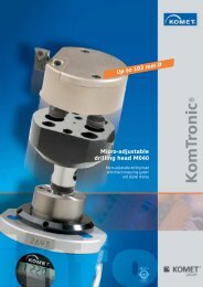
U-Achssystem 64<br />
63<br />
optional mit direktem Wegmesssystem<br />
U-Axis System 64<br />
64<br />
Optional with Linear Encoder 64<br />
Die U-Achs-Vorrüstung 66<br />
für Werkzeugmaschinen 66<br />
U-Axis Pre-Installation 66<br />
for Machine Tools 66<br />
HQB Technology (High Quality Balance) 68<br />
<strong>KOMET</strong>® KomDrive HQB Plandrehkopf 68<br />
<strong>KOMET</strong>® KomDrive HQB Facing Head 68<br />
<strong>KOMET</strong>® Quatron hi.feed Fräser 70<br />
<strong>KOMET</strong>® Quatron hi.feed Milling cutter 70<br />
Anwendungsbeispiele 72<br />
Application Examples 72<br />
Fräser 73<br />
Milling Cutter 73<br />
Aufnahme 74<br />
<strong>TOOLS</strong> <strong>PLUS</strong> <strong>IDEAS</strong><br />
Adaptor 74<br />
Richtwerte für das Fräsen 75<br />
Guideline Values for Milling 75<br />
ISO-Passungen H7 ab Lager! 76<br />
ISO H7 Fittings Available Ex-Stock! 76<br />
Ab Lager lieferbar! 78<br />
Available from Stock! 78<br />
Neue Beschichtungen DBF und DBC 80<br />
Reamax TS® mit ABS® Anbindung 80<br />
DAH Zero® 80<br />
mit breitem Durchmesserspektrum für durchgängig integrierte<br />
Rundlaufgenauigkeit beim Reiben 80<br />
New DBC and DBF Coatings 80<br />
Reamax TS® with ABS® Connection 80<br />
DAH Zero® 80<br />
with its wide range of diameters for continuously integrated<br />
concentricity when reaming 80<br />
Reibkopf 82<br />
Reaming Head 82<br />
Halter 83<br />
Holder 83<br />
DAH Zero® Halter 84<br />
DAH Zero® Holder 84<br />
Bedienungsanleitung DAH Zero® 85<br />
Einbauteile / Zubehör 85<br />
Operating Instruction DAH Zero® 85<br />
Assembly Parts / Accessories 85<br />
Werkzeugempfehlung 86<br />
Tool Recommendation 86<br />
Hightech für kleinere Durchmesser 88<br />
Hightech for Smaller Diameters 88<br />
Voll-DST-Reibahle 90<br />
Solid DST Reamer 90<br />
Werkzeugempfehlung 91<br />
Tool Recommendation 91<br />
Wendeschneidplatten-Technolgie 92<br />
verändert den Takt beim Reiben 92<br />
Indexable Insert Technology Changes the Cycle when Reaming<br />
92<br />
Reiben mit einstellbaren Schneidplatten<br />
Reaming with Adjustable Inserts 94<br />
94<br />
Vollhartmetallfräser 96<br />
Solid Carbide Milling Cutter 96<br />
Übersicht Vollhartmetallfräser 98<br />
Overview of the Solid Carbide Milling Cutter<br />
Schaftfräser UNI 100<br />
(F044 universal) 100<br />
98<br />
End Milling Cutter UNI<br />
Schaftfräser UNI 101<br />
(F064 universal) 101<br />
100<br />
End Milling Cutter UNI<br />
Schafträser HPC 102<br />
101<br />
HPC Schafträser (Liebrich) 102<br />
End Milling Cutter HPC 102<br />
Schaftfräser XH (F072 finishing) 103<br />
Schaftfräser XH 103<br />
End Milling Cutter XH 103<br />
Schaftfräser XH (F041 finishing) 104<br />
Schaftfräser XH 104<br />
End Milling Cutter XH 104<br />
Schruppfräser (F544 roughing) 105<br />
Schruppfräser 105<br />
Roughing End Mill 105<br />
Kugelfräser 106<br />
Kugelfräser (F344 Ball end cutter) 106<br />
Spherical Cutter 106<br />
Kugelfräser XH 107<br />
Kugelfräser XH (F322 Ball end cutter) 107<br />
Spherical Cutter XH 107<br />
Kugelfräser XH (F942 Ball end cutter)<br />
Kugelfräser XH 108<br />
108<br />
Spherical Cutter XH 108<br />
Schaftfräser (F144 with corner radius) 109<br />
Schaftfräser 109<br />
End Milling Cutter 109<br />
Schaftfräser (F142 with corner radius)<br />
Schaftfräser XH 110<br />
110<br />
End Milling Cutter XH 110<br />
Schaftfräser (F170 with corner radius)<br />
Schaftfräser XH 111<br />
111<br />
End Milling Cutter XH 111<br />
Torusfräser XH (F742)<br />
Torusfräser XH 112<br />
112<br />
Torus Milling Cutter XH 112<br />
Fasfräser (FK) 113<br />
Fasfräser 113<br />
Chamfer Milling Cutter 113<br />
Radiusfräser XH (FZ) 114<br />
Radiusfräser 114<br />
Radius Milling Cutter 114<br />
Schaftfräser (F065 Aluminium)<br />
Schaftfräser AL 115<br />
115<br />
End Milling Cutter AL 115<br />
Schaftfräser HF (JEL-Katalog)<br />
Schaftfräser HF 116<br />
116<br />
End Milling Cutter HF<br />
Schaftfräser (FJ) 117<br />
Schaftfräser AL 117<br />
116<br />
End Milling Cutter AL 117<br />
Richtwerte für das Fräsen 118<br />
Guideline Values for Milling 118<br />
Technische Hinweise<br />
Technical Notes 120<br />
120<br />
Korrekturfaktor Kf 121<br />
Correction factor Kf<br />
Gewindeformer 122<br />
121<br />
HSS-E mit Hartmetallleisten 122<br />
Roll Form Tap 122<br />
HSS-E with carbide strips<br />
Gewindeformer 124<br />
122<br />
Roll Form Tap 124<br />
Maschinengewindeformer 126<br />
Vollhartmetallgewindeformer<br />
Thread Former 126<br />
126<br />
Solid Carbide Thread Former 126<br />
Maschinengewindeformer<br />
Thread Former 128<br />
128<br />
Richtwerte für das Gewindeformen 130<br />
Guideline Values for Thread Forming<br />
Synchro-Gewindeschneidfutter 132<br />
130<br />
Synchro Tapping Chuck 132<br />
Synchro-Gewindeschneidfutter 134<br />
Synchro Tapping Chuck 134<br />
Bohrgewindefräser 136<br />
für Aluminiumguss 136<br />
Drill Thread Milling Cutter 136<br />
for Cast Aluminium 136<br />
Bohrgewindefräser 138<br />
Drill Thread Milling Tool 138<br />
Richtwerte für das Gewindefräsen 139<br />
M 139<br />
Guideline Values for Thread Milling<br />
PKD-Plan- und Einschraubfräser 140<br />
139<br />
PCD Face-Milling and Screw-In Cutters 140<br />
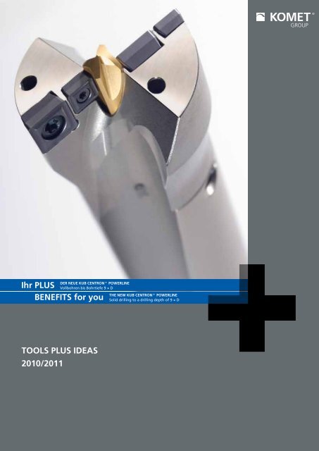
DEr nEUE KUB cEnTrOn® POwErLInE<br />
Vollbohren bis Bohrtiefe 9 × D<br />
BEnEfITS for you<br />
THE nEw KUB cEnTrOn® POwErLInE<br />
Solid drilling to a drilling depth of 9 × D<br />
PKD-Planfräser 142<br />
PKD-Bohrnutenfräser 142<br />
PCD Face Milling Cutter 142<br />
PCD Slot Milling Cutter 142<br />
Aufnahme 143<br />
Adapter 143<br />
PKD Planfräser 144<br />
PCD Face Milling Cutter<br />
PKD Planfräser 146<br />
144<br />
PCD Face Milling Cutter 146<br />
Noch perfekter verbunden 148<br />
Even more perfectly joined 148<br />
<strong>KOMET</strong> SERVICE 150<br />
Der neue <strong>KOMET</strong> SERVICE 150<br />
The new <strong>KOMET</strong> SERVICE 150<br />
<strong>KOMET</strong> SERVICE – 151<br />
Ihr Plus für eine effiziente Fertigung 151<br />
<strong>KOMET</strong> SERVICE – 151<br />
Your advantage for efficient production 151<br />
Die Fabrik der Ideen 152<br />
The ideas factory 153<br />
Das <strong>PLUS</strong> 154<br />
für unsere Kunden und die Umwelt 154<br />
The <strong>PLUS</strong> 154<br />
for our customers and the environment 154
2<br />
Mit innovativen Lösungen und Werkzeugkonzepten<br />
für die Bohrungsbearbeitung nimmt<br />
die <strong>KOMET</strong> <strong>GROUP</strong> weltweit eine führende<br />
Marktposition ein. Unsere Entwicklungen für<br />
Bohren, Gewinden und Reiben tragen maßgeblich<br />
zum Erfolg unserer Kunden bei.<br />
<strong>KOMET</strong> <strong>GROUP</strong> – fokussiert auf die anspruchsvolle<br />
Bohrungsbearbeitung.<br />
Vollbohren Solid Drilling Seite · Page<br />
<strong>KOMET</strong> KUB® Drillmax<br />
Hochleistungsbohrer für x 3 – 16 mm<br />
<strong>KOMET</strong> KUB K2®<br />
Wechselkopfbohrer für x 12 – 15,9 mm<br />
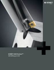
<strong>KOMET</strong> KUB Pentron®<br />
Vollbohren bis x 44,5 mm<br />
<strong>KOMET</strong> KUB Centron® Powerline<br />
Vollbohren bis Bohrtiefe 9 × D<br />
Aufbohren Roughing<br />
<strong>KOMET</strong>® PreciKom<br />
Schruppen und Schlichten in einem Arbeitsgang<br />
Feinbohren Fine Boring<br />
<strong>KOMET</strong> MicroKom® BluFlex<br />
Feinbohrsystem mit Bluetooth® Technologie<br />
Aufnahmen Adaptors<br />
<strong>KOMET</strong> ABS® HMD<br />
Dämpfungselement<br />
<strong>KOMET</strong> KUB® Drillmax<br />
High-performance drill for diameter 3 – 16 mm<br />
<strong>KOMET</strong> KUB K2®<br />
Replaceable head drill for diameter 12 – 15,9 mm<br />
<strong>KOMET</strong> KUB Pentron®<br />
Solid drilling until diameter 44,5 mm<br />
<strong>KOMET</strong> KUB Centron® Powerline<br />
Solid drilling to a drilling depth of 9 × D<br />
<strong>KOMET</strong>® PreciKom<br />
Roughing and finishing in one step<br />
<strong>KOMET</strong> MicroKom® BluFlex<br />
Precision boring system with Bluetooth® technology<br />
<strong>KOMET</strong> ABS® HMD<br />
Damping element<br />
KomTronic® · Planschieber KomTronic® · Facing Head<br />
<strong>KOMET</strong> KomTronic®<br />
U-Achssystem optional mit direktem Wegmesssystem<br />
<strong>KOMET</strong> KomTronic® mechatronic-ready<br />
U-Achs-Vorrüstung für Werkzeugmaschinen<br />
<strong>KOMET</strong>® KomDrive<br />
Plandrehkopf mit HQB-Technologie<br />
<strong>KOMET</strong> KomTronic®<br />
U-axis system optional with linear encoder<br />
<strong>KOMET</strong> KomTronic® mechatronic-ready<br />
U-axis pre-installation for machine tools<br />
<strong>KOMET</strong>® KomDrive<br />
Facing head with HQB technology<br />
4 – 17<br />
18 – 23<br />
24 – 43<br />
44 – 45<br />
46 – 49<br />
50 – 59<br />
60 – 63<br />
64 – 65<br />
66 – 67<br />
68 – 69<br />
Fräsen Milling Seite · Page<br />
<strong>KOMET</strong>® Quatron hi.feed<br />
Fräser (aufschraubbar)<br />
With innovative solutions and tool designs for<br />
bore machining, the <strong>KOMET</strong> <strong>GROUP</strong> holds a<br />
leading market role worldwide. Our developments<br />
for boring, tapping and reaming contribute<br />
enormously to our customers' success.<br />
<strong>KOMET</strong> <strong>GROUP</strong> – focussed on the demands<br />
of bore machining.<br />
<strong>KOMET</strong>® Quatron hi.feed<br />
Mill (screw-on)<br />
70 – 75
Reiben Reaming Seite · Page<br />
Vorzugsreihe H7 Preferred Range H7 76 – 79<br />
DIHART Reamax® TS<br />
Neue Beschichtung für Alu / Guss Bearbeitung<br />
Halter mit ABS® Anbindung<br />
DAH Zero® Halter<br />
DIHART® Fullmax<br />
Voll-DST-Reibahle<br />
DIHART® Duomax<br />
Schneidring mit Wendeschneidplatten-Technologie<br />
DIHART® MicroSet System<br />
Reibwerkzeug mit einzeln einstellbaren Schneidplatten<br />
DIHART Reamax® TS<br />
New coating for aluminium/cast iron machining<br />
Holder with ABS® connection<br />
DAH Zero® holder<br />
DIHART® Fullmax<br />
Solid DST reamer<br />
DIHART® Duomax<br />
Cutting ring with insert technology<br />
DIHART® MicroSet System<br />
Reamer with individually-adjustable inserts<br />
80 – 87<br />
88 – 91<br />
92 – 93<br />
94 – 95<br />
Gewinden Threading Seite · Page<br />
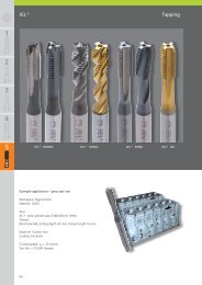
JEL® Fräser<br />
Schrupp-, Schlicht-, Kugel-, Torus-, Fas- und<br />
Radiusfräser<br />
JEL® MOREX R<br />
Gewindeformer<br />
JEL® MOREX S<br />
Maschinengewindeformer<br />
JEL® JSF<br />
Synchro-Gewindeschneidfutter<br />
JEL® BGF<br />
Bohrgewindefräser<br />
JEL® PKD<br />
Fräser<br />
KUB Centron® Powerline<br />
JEL® Milling Cutter<br />
Roughing, finishing, ball nosed, torus, chamfer and<br />
radius milling tools<br />
JEL® MOREX R<br />
Roll form tap<br />
JEL® MOREX S<br />
Machine thread former<br />
JEL® JSF<br />
Synchro tapping chuck<br />
JEL® BGF<br />
Drill thread milling cutter<br />
JEL® PCD<br />
Milling cutter<br />
96 – 121<br />
122 – 125<br />
126 – 131<br />
132 – 135<br />
136 – 139<br />
140 – 147<br />
<strong>KOMET</strong> ABS® <strong>KOMET</strong> ABS® 148 – 149<br />
<strong>KOMET</strong> SERVICE <strong>KOMET</strong> SERVICE 150 – 151<br />
IDEEN-FABRIK+ IDEEN-FABRIK+ 152 – 153<br />
3
4<br />
<strong>KOMET</strong> KUB® Drillmax<br />
Hochleistungsbohrer<br />
für kleine Durchmesser<br />
Die neuen Hochleistungs-Vollhartmetallbohrer<br />
KUB® Drillmax runden unser Angebot für die<br />
Bohrungsdurchmesser 3 - 16 mm und in Längen-/<br />
Durchmesserverhältnissen 5×D und 7-8×D ab.<br />
Optimierte, spezielle Spannuten ermöglichen eine<br />
ideale Spanabfuhr und eine höchst produktive<br />
Bearbeitung.<br />
Ausführung:<br />
- Bohrerdurchmesser: 3,00 – 16,00 mm<br />
- Bohrungstoleranz: IT9 (erzielbar)<br />
- Bohrtiefe: 5×D und 7-8×D<br />
- Schaftform: DIN 6535 HA / HE<br />
- Beschichtung: TiAlN<br />
- Spitzenwinkel: 140°<br />
- Spiralwinkel: 30°<br />
- Innere Kühlschmierstoffzufuhr<br />
Ihr <strong>PLUS</strong>:<br />
Exzellente Bohrungstoleranzen<br />
Optimale Spanabfuhr durch spezielle Spannuten<br />
Optimales Bearbeitungsergebnis durch eine<br />
gute Abstimmung von Hartmetall und Beschichtung<br />
auf die Bohrergeometrie<br />
Hohe Standzeiten durch leistungsfähige Beschichtung<br />
High-Performance Drill<br />
for Small Diameters<br />
The new KUB® Drillmax high-performance solid<br />
carbide drills complete our range for drill diameters<br />
of 3 to 16 mm and length/diameter ratios of 5×D<br />
and 7-8×D.<br />
Optimised, special flutes are ideal for removing<br />
chips and for highly productive machining.<br />
Variant:<br />
- Drill diameter: 3.00 – 16.00 mm<br />
- Hole tolerance: IT9 (achievable)<br />
- Drilling depth: 5×D and 7-8×D<br />
- Shank shape: DIN 6535 HA / HE<br />
- Coating: TiAlN<br />
- Point angle: 140°<br />
- Helix angle: 30°<br />
- Internal coolant supply<br />
BENEFITS for you:<br />
Excellent hole tolerances<br />
Optimum chip removal thanks to special flutes<br />
Optimum machining result thanks to good<br />
coordination of carbide and coating with drill<br />
geometry<br />
Long tool edge life thanks to effective coating
6<br />
<strong>KOMET</strong> KUB® Drillmax<br />
VHM-Hochleistungsbohrer<br />
- Zylinderschaft nach DIN 6535 HA / HE<br />
- rechtsschneidend<br />
x d<br />
l N<br />
L<br />
X 3,0 – 16,0 mm<br />
5×D § § $ & & & & X $ & X<br />
§ sehr gut $ gut & möglich X nicht möglich § very good $ good & possible X not possible<br />
5 × D<br />
für Werkstückstoff<br />
for material<br />
X D X d × l<br />
DIN 6535 HA DIN 6535 HE<br />
L N P M K N S H<br />
Bestell-Nr. · Order No. Bestell-Nr. · Order No.<br />
p<br />
3,0 6 × 36 V03 03000.112730 V03 03000.212730 66 24 0,016<br />
3,1 6 × 36 V03 03100.112730 V03 03100.212730 66 24 0,016<br />
3,2 6 × 36 V03 03200.112730 V03 03200.212730 66 24 0,017<br />
3,3<br />
3,4<br />
6 × 36<br />
6 × 36<br />
V03 03300.112730<br />
V03 03400.112730<br />
V03 03300.212730<br />
V03 03400.212730<br />
66<br />
66<br />
24<br />
24<br />
0,017<br />
0,017<br />
§ $ $<br />
3,5 6 × 36 V03 03500.112730 V03 03500.212730 66 24 0,018<br />
3,6 6 × 36 V03 03600.112730 V03 03600.212730 66 24 0,018<br />
3,7 6 × 36 V03 03700.112730 V03 03700.212730 66 24 0,018<br />
3,8 6 × 36 V03 03800.112730 V03 03800.212730 74 30 0,018<br />
3,9 6 × 36 V03 03900.112730 V03 03900.212730 74 30 0,018<br />
4,0 6 × 36 V03 04000.112730 V03 04000.212730 74 30 0,018<br />
4,1 6 × 36 V03 04100.112730 V03 04100.212730 74 30 0,019<br />
4,2<br />
4,3<br />
6 × 36<br />
6 × 36<br />
V03 04200.112730<br />
V03 04300.112730<br />
V03 04200.212730<br />
V03 04300.212730<br />
74<br />
74<br />
30<br />
30<br />
0,019<br />
0,019<br />
§ $ $<br />
4,4 6 × 36 V03 04400.112730 V03 04400.212730 74 30 0,019<br />
4,5 6 × 36 V03 04500.112730 V03 04500.212730 74 30 0,019<br />
4,6 6 × 36 V03 04600.112730 V03 04600.212730 74 30 0,019<br />
4,7 6 × 36 V03 04700.112730 V03 04700.212730 74 30 0,019<br />
4,8 6 × 36 V03 04800.112730 V03 04800.212730 82 35 0,020<br />
4,9 6 × 36 V03 04900.112730 V03 04900.212730 82 35 0,020<br />
5,0 6 × 36 V03 05000.112730 V03 05000.212730 82 35 0,020<br />
5,1 6 × 36 V03 05100.112730 V03 05100.212730 82 35 0,021<br />
5,2 6 × 36 V03 05200.112730 V03 05200.212730 82 35 0,021<br />
5,3 6 × 36 V03 05300.112730 V03 05300.212730 82 35 0,022<br />
5,4<br />
5,5<br />
6 × 36<br />
6 × 36<br />
V03 05400.112730<br />
V03 05500.112730<br />
V03 05400.212730<br />
V03 05500.212730<br />
82<br />
82<br />
35<br />
35<br />
0,022<br />
0,023<br />
§ $ $<br />
5,54 6 × 36 V03 05540.112730 V03 05540.212730 82 35 0,023<br />
5,6 6 × 36 V03 05600.112730 V03 05600.212730 82 35 0,023<br />
5,7 6 × 36 V03 05700.112730 V03 05700.212730 82 35 0,024<br />
5,8 6 × 36 V03 05800.112730 V03 05800.212730 82 35 0,024<br />
5,9 6 × 36 V03 05900.112730 V03 05900.212730 82 35 0,025<br />
6,0 6 × 36 V03 06000.112730 V03 06000.212730 82 35 0,025<br />
6,1 8 × 36 V03 06100.112730 V03 06100.212730 91 43 0,027<br />
6,2 8 × 36 V03 06200.112730 V03 06200.212730 91 43 0,027<br />
6,3 8 × 36 V03 06300.112730 V03 06300.212730 91 43 0,030<br />
6,4 8 × 36 V03 06400.112730 V03 06400.212730 91 43 0,030<br />
6,5 8 × 36 V03 06500.112730 V03 06500.212730 91 43 0,032 § $ $<br />
6,6 8 × 36 V03 06600.112730 V03 06600.212730 91 43 0,032<br />
6,7 8 × 36 V03 06700.112730 V03 06700.212730 91 43 0,032<br />
6,8 8 × 36 V03 06800.112730 V03 06800.212730 91 43 0,035<br />
6,9 8 × 36 V03 06900.112730 V03 06900.212730 91 43 0,035<br />
Hinweis: mit Whistle-Notch Spannfläche nach DIN 6535 HE,<br />
Lieferzeit 1 Woche (Mindestabnahme: 3 Stück)<br />
High-Performance Solid Carbide Drill<br />
- cylindrical shank DIN 6535 HA / HE<br />
- R.H. cutting<br />
Note: with whistle notch clamping surface conforming to<br />
DIN 6535 HE, Delivery time 1 week (min. purchase: 3 pieces)<br />
x D<br />
140°
5×D<br />
<strong>KOMET</strong> KUB® Drillmax<br />
VHM-Hochleistungsbohrer High-Performance Solid Carbide Drill<br />
5 × D<br />
für Werkstückstoff<br />
for material<br />
X D X d × l<br />
DIN 6535 HA DIN 6535 HE<br />
L N P M K N S H<br />
Bestell-Nr. · Order No. Bestell-Nr. · Order No.<br />
p<br />
7,0 8 × 36 V03 07000.112730 V03 07000.212730 91 43 0,037<br />
7,1 8 × 36 V03 07100.112730 V03 07100.212730 91 43 0,037<br />
7,2 8 × 36 V03 07200.112730 V03 07200.212730 91 43 0,039<br />
7,3 8 × 36 V03 07300.112730 V03 07300.212730 91 43 0,039<br />
7,4 8 × 36 V03 07400.112730 V03 07400.212730 91 43 0,040<br />
7,43<br />
7,5<br />
8 × 36<br />
8 × 36<br />
V03 07430.112730<br />
V03 07500.112730<br />
V03 07430.212730<br />
V03 07500.212730<br />
91<br />
91<br />
43<br />
43<br />
0,040<br />
0,040 § $ $<br />
7,6 8 × 36 V03 07600.112730 V03 07600.212730 91 43 0,041<br />
7,7 8 × 36 V03 07700.112730 V03 07700.212730 91 43 0,041<br />
7,8 8 × 36 V03 07800.112730 V03 07800.212730 91 43 0,043<br />
7,9 8 × 36 V03 07900.112730 V03 07900.212730 91 43 0,043<br />
8,0 8 × 36 V03 08000.112730 V03 08000.212730 91 43 0,044<br />
8,1 10 × 40 V03 08100.112730 V03 08100.212730 103 49 0,045<br />
8,2 10 × 40 V03 08200.112730 V03 08200.212730 103 49 0,045<br />
8,3 10 × 40 V03 08300.112730 V03 08300.212730 103 49 0,047<br />
8,4 10 × 40 V03 08400.112730 V03 08400.212730 103 49 0,047<br />
8,5 10 × 40 V03 08500.112730 V03 08500.212730 103 49 0,050<br />
8,6 10 × 40 V03 08600.112730 V03 08600.212730 103 49 0,050<br />
8,7 10 × 40 V03 08700.112730 V03 08700.212730 103 49 0,052<br />
8,8 10 × 40 V03 08800.112730 V03 08800.212730 103 49 0,052<br />
8,9 10 × 40 V03 08900.112730 V03 08900.212730 103 49 0,055<br />
9,0 10 × 40 V03 09000.112730 V03 09000.212730 103 49 0,055<br />
9,1 10 × 40 V03 09100.112730 V03 09100.212730 103 49 0,057 § $ $<br />
9,2 10 × 40 V03 09200.112730 V03 09200.212730 103 49 0,057<br />
9,3 10 × 40 V03 09300.112730 V03 09300.212730 103 49 0,062<br />
9,4 10 × 40 V03 09400.112730 V03 09400.212730 103 49 0,062<br />
9,5 10 × 40 V03 09500.112730 V03 09500.212730 103 49 0,067<br />
9,54 10 × 40 V03 09540.112730 V03 09540.212730 103 49 0,067<br />
9,6 10 × 40 V03 09600.112730 V03 09600.212730 103 49 0,067<br />
9,7 10 × 40 V03 09700.112730 V03 09700.212730 103 49 0,072<br />
9,8 10 × 40 V03 09800.112730 V03 09800.212730 103 49 0,072<br />
9,9 10 × 40 V03 09900.112730 V03 09900.212730 103 49 0,077<br />
10,0 10 × 40 V03 10000.112730 V03 10000.212730 103 49 0,077<br />
10,1 12 × 45 V03 10100.112730 V03 10100.212730 118 56 0,080<br />
10,2 12 × 45 V03 10200.112730 V03 10200.212730 118 56 0,085<br />
10,3 12 × 45 V03 10300.112730 V03 10300.212730 118 56 0,090<br />
10,4 12 × 45 V03 10400.112730 V03 10400.212730 118 56 0,094<br />
10,5 12 × 45 V03 10500.112730 V03 10500.212730 118 56 0,097<br />
10,6 12 × 45 V03 10600.112730 V03 10600.212730 118 56 0,100<br />
10,7 12 × 45 V03 10700.112730 V03 10700.212730 118 56 0,102<br />
10,8 12 × 45 V03 10800.112730 V03 10800.212730 118 56 0,105<br />
10,9 12 × 45 V03 10900.112730 V03 10900.212730 118 56 0,107<br />
11,0 12 × 45 V03 11000.112730 V03 11000.212730 118 56 0,110<br />
11,1 12 × 45 V03 11100.112730 V03 11100.212730 118 56 0,112 § $ $<br />
11,2 12 × 45 V03 11200.112730 V03 11200.212730 118 56 0,115<br />
11,3 12 × 45 V03 11300.112730 V03 11300.212730 118 56 0,117<br />
11,4 12 × 45 V03 11400.112730 V03 11400.212730 118 56 0,120<br />
11,5 12 × 45 V03 11500.112730 V03 11500.212730 118 56 0,122<br />
11,54 12 × 45 V03 11540.112730 V03 11540.212730 118 56 0,122<br />
11,6 12 × 45 V03 11600.112730 V03 11600.212730 118 56 0,125<br />
11,7 12 × 45 V03 11700.112730 V03 11700.212730 118 56 0,127<br />
11,8 12 × 45 V03 11800.112730 V03 11800.212730 118 56 0,130<br />
11,9 12 × 45 V03 11900.112730 V03 11900.212730 118 56 0,132<br />
12,0 12 × 45 V03 12000.112730 V03 12000.212730 118 56 0,135<br />
12,5 14 × 45 V03 12500.112730 V03 12500.212730 124 60 0,180<br />
12,8 14 × 45 V03 12800.112730 V03 12800.212730 124 60 0,180<br />
13,0 14 × 45 V03 13000.112730 V03 13000.212730 124 60 0,182<br />
13,3 14 × 45 V03 13300.112730 V03 13300.212730 124 60 0,182 § $ $<br />
13,5 14 × 45 V03 13500.112730 V03 13500.212730 124 60 0,185<br />
13,8 14 × 45 V03 13800.112730 V03 13800.212730 124 60 0,185<br />
14,0 14 × 45 V03 14000.112730 V03 14000.212730 124 60 0,188<br />
14,5 16 × 48 V03 14500.112730 V03 14500.212730 133 63 0,240<br />
14,8 16 × 48 V03 14800.112730 V03 14800.212730 133 63 0,240<br />
15,0<br />
15,5<br />
16 × 48<br />
16 × 48<br />
V03 15000.112730<br />
V03 15500.112730<br />
V03 15000.212730<br />
V03 15500.212730<br />
133<br />
133<br />
63<br />
63<br />
0,250<br />
0,270 § $ $<br />
15,8 16 × 48 V03 15800.112730 V03 15800.212730 133 63 0,270<br />
16,0 16 × 48 V03 16000.112730 V03 16000.212730 133 63 0,282<br />
Weitere Durchmesser auf Anfrage.<br />
Richtwerte für das Vollbohren: Seite 14<br />
Other diameters on request.<br />
Guideline values for solid drilling: Page 14<br />
7
8<br />
<strong>KOMET</strong> KUB® Drillmax<br />
VHM-Hochleistungsbohrer<br />
- Zylinderschaft nach DIN 6535 HA / HE<br />
- rechtsschneidend<br />
x d<br />
l N<br />
L<br />
X 3,0 – 16,0 mm<br />
7-8×D § § $ & & & & X $ & X<br />
§ sehr gut $ gut & möglich X nicht möglich § very good $ good & possible X not possible<br />
7 – 8 × D<br />
für Werkstückstoff<br />
for material<br />
X D X d × l<br />
DIN 6535 HA<br />
Bestell-Nr. · Order No.<br />
DIN 6535 HE<br />
Bestell-Nr. · Order No.<br />
L N<br />
p<br />
P M K N S H<br />
3,0 6 × 36 V04 03000.112730 V04 03000.212730 70 28 0,017<br />
3,1 6 × 36 V04 03100.112730 V04 03100.212730 70 28 0,017<br />
3,2 6 × 36 V04 03200.112730 V04 03200.212730 70 28 0,017<br />
3,3<br />
3,4<br />
6 × 36<br />
6 × 36<br />
V04 03300.112730<br />
V04 03400.112730<br />
V04 03300.212730<br />
V04 03400.212730<br />
70<br />
70<br />
28<br />
28<br />
0,017<br />
0,018<br />
§ $ $<br />
3,5 6 × 36 V04 03500.112730 V04 03500.212730 70 28 0,018<br />
3,6 6 × 36 V04 03600.112730 V04 03600.212730 70 28 0,018<br />
3,7 6 × 36 V04 03700.112730 V04 03700.212730 70 28 0,018<br />
3,8 6 × 36 V04 03800.112730 V04 03800.212730 80 36 0,019<br />
3,9 6 × 36 V04 03900.112730 V04 03900.212730 80 36 0,019<br />
4,0 6 × 36 V04 04000.112730 V04 04000.212730 80 36 0,019<br />
4,1 6 × 36 V04 04100.112730 V04 04100.212730 80 36 0,020<br />
4,2<br />
4,3<br />
6 × 36<br />
6 × 36<br />
V04 04200.112730<br />
V04 04300.112730<br />
V04 04200.212730<br />
V04 04300.212730<br />
80<br />
80<br />
36<br />
36<br />
0,020<br />
0,020<br />
§ $ $<br />
4,4 6 × 36 V04 04400.112730 V04 04400.212730 80 36 0,021<br />
4,5 6 × 36 V04 04500.112730 V04 04500.212730 80 36 0,021<br />
4,6 6 × 36 V04 04600.112730 V04 04600.212730 80 36 0,021<br />
4,7 6 × 36 V04 04700.112730 V04 04700.212730 80 36 0,021<br />
4,8 6 × 36 V04 04800.112730 V04 04800.212730 92 45 0,023<br />
4,9 6 × 36 V04 04900.112730 V04 04900.212730 92 45 0,023<br />
5,0 6 × 36 V04 05000.112730 V04 05000.212730 92 45 0,024<br />
5,1 6 × 36 V04 05100.112730 V04 05100.212730 92 45 0,025<br />
5,2 6 × 36 V04 05200.112730 V04 05200.212730 92 45 0,025<br />
5,3 6 × 36 V04 05300.112730 V04 05300.212730 92 45 0,026<br />
5,4<br />
5,5<br />
6 × 36<br />
6 × 36<br />
V04 05400.112730<br />
V04 05500.112730<br />
V04 05400.212730<br />
V04 05500.212730<br />
92<br />
92<br />
45<br />
45<br />
0,027<br />
0,027<br />
§ $ $<br />
5,54 6 × 36 V04 05540.112730 V04 05540.212730 92 45 0,027<br />
5,6 6 × 36 V04 05600.112730 V04 05600.212730 92 45 0,028<br />
5,7 6 × 36 V04 05700.112730 V04 05700.212730 92 45 0,029<br />
5,8 6 × 36 V04 05800.112730 V04 05800.212730 92 45 0,030<br />
5,9 6 × 36 V04 05900.112730 V04 05900.212730 92 45 0,030<br />
6,0 6 × 36 V04 06000.112730 V04 06000.212730 92 45 0,031<br />
6,1 8 × 36 V04 06100.112730 V04 06100.212730 100 52 0,032<br />
6,2 8 × 36 V04 06200.112730 V04 06200.212730 100 52 0,034<br />
6,3 8 × 36 V04 06300.112730 V04 06300.212730 100 52 0,036<br />
6,4<br />
6,5<br />
8 × 36<br />
8 × 36<br />
V04 06400.112730<br />
V04 06500.112730<br />
V04 06400.212730<br />
V04 06500.212730<br />
100<br />
100<br />
52<br />
52<br />
0,038<br />
0,039<br />
§ $ $<br />
6,6 8 × 36 V04 06600.112730 V04 06600.212730 100 52 0,040<br />
6,7 8 × 36 V04 06700.112730 V04 06700.212730 100 52 0,041<br />
6,8 8 × 36 V04 06800.112730 V04 06800.212730 100 52 0,043<br />
Hinweis: mit Whistle-Notch Spannfläche nach DIN 6535 HE,<br />
Lieferzeit 1 Woche (Mindestabnahme: 3 Stück)<br />
High-Performance Solid Carbide Drill<br />
- cylindrical shank DIN 6535 HA / HE<br />
- R.H. cutting<br />
Note: with whistle notch clamping surface conforming to<br />
DIN 6535 HE, Delivery time 1 week (min. purchase: 3 pieces)<br />
x D<br />
140°
7 – 8×D<br />
VHM-Hochleistungsbohrer High-Performance Solid Carbide Drill<br />
7 – 8 × D<br />
für Werkstückstoff<br />
for material<br />
X D X d × l<br />
DIN 6535 HA DIN 6535 HE<br />
L N P M K N S H<br />
Bestell-Nr. · Order No. Bestell-Nr. · Order No.<br />
p<br />
6,9 8 × 36 V04 06900.112730 V04 06900.212730 108 60 0,045<br />
7,0 8 × 36 V04 07000.112730 V04 07000.212730 108 60 0,045<br />
7,1 8 × 36 V04 07100.112730 V04 07100.212730 108 60 0,046<br />
7,2 8 × 36 V04 07200.112730 V04 07200.212730 108 60 0,047<br />
7,3 8 × 36 V04 07300.112730 V04 07300.212730 108 60 0,047<br />
7,4 8 × 36 V04 07400.112730 V04 07400.212730 108 60 0,048<br />
7,43 8 × 36 V04 07430.112730 V04 07430.212730 108 60 0,048 § $ $<br />
7,5 8 × 36 V04 07500.112730 V04 07500.212730 108 60 0,049<br />
7,6 8 × 36 V04 07600.112730 V04 07600.212730 108 60 0,050<br />
7,7 8 × 36 V04 07700.112730 V04 07700.212730 108 60 0,050<br />
7,8 8 × 36 V04 07800.112730 V04 07800.212730 108 60 0,051<br />
7,9 8 × 36 V04 07900.112730 V04 07900.212730 108 60 0,052<br />
8,0 8 × 36 V04 08000.112730 V04 08000.212730 108 60 0,053<br />
8,1 10 × 40 V04 08100.112730 V04 08100.212730 122 68 0,055<br />
8,2 10 × 40 V04 08200.112730 V04 08200.212730 122 68 0,057<br />
8,3 10 × 40 V04 08300.112730 V04 08300.212730 122 68 0,060<br />
8,4 10 × 40 V04 08400.112730 V04 08400.212730 122 68 0,062<br />
8,5 10 × 40 V04 08500.112730 V04 08500.212730 122 68 0,065<br />
8,6 10 × 40 V04 08600.112730 V04 08600.212730 122 68 0,067<br />
8,7 10 × 40 V04 08700.112730 V04 08700.212730 122 68 0,070<br />
8,8 10 × 40 V04 08800.112730 V04 08800.212730 122 68 0,072<br />
8,9 10 × 40 V04 08900.112730 V04 08900.212730 122 68 0,075<br />
9,0 10 × 40 V04 09000.112730 V04 09000.212730 122 68 0,077<br />
9,1 10 × 40 V04 09100.112730 V04 09100.212730 130 76 0,080 § $ $<br />
9,2 10 × 40 V04 09200.112730 V04 09200.212730 130 76 0,082<br />
9,3 10 × 40 V04 09300.112730 V04 09300.212730 130 76 0,085<br />
9,4 10 × 40 V04 09400.112730 V04 09400.212730 130 76 0,087<br />
9,5 10 × 40 V04 09500.112730 V04 09500.212730 130 76 0,090<br />
9,54 10 × 40 V04 09540.112730 V04 09540.212730 130 76 0,090<br />
9,6 10 × 40 V04 09600.112730 V04 09600.212730 130 76 0,090<br />
9,7 10 × 40 V04 09700.112730 V04 09700.212730 130 76 0,092<br />
9,8 10 × 40 V04 09800.112730 V04 09800.212730 130 76 0,095<br />
9,9 10 × 40 V04 09900.112730 V04 09900.212730 130 76 0,097<br />
10,0 10 × 40 V04 10000.112730 V04 10000.212730 130 76 0,099<br />
10,1 12 × 45 V04 10100.112730 V04 10100.212730 152 90 0,102<br />
10,2 12 × 45 V04 10200.112730 V04 10200.212730 152 90 0,105<br />
10,3 12 × 45 V04 10300.112730 V04 10300.212730 152 90 0,110<br />
10,4 12 × 45 V04 10400.112730 V04 10400.212730 152 90 0,112<br />
10,5 12 × 45 V04 10500.112730 V04 10500.212730 152 90 0,115<br />
10,6 12 × 45 V04 10600.112730 V04 10600.212730 152 90 0,117<br />
10,7 12 × 45 V04 10700.112730 V04 10700.212730 152 90 0,120<br />
10,8 12 × 45 V04 10800.112730 V04 10800.212730 152 90 0,122<br />
10,9 12 × 45 V04 10900.112730 V04 10900.212730 152 90 0,125<br />
11,0 12 × 45 V04 11000.112730 V04 11000.212730 152 90 0,127<br />
11,1 12 × 45 V04 11100.112730 V04 11100.212730 152 90 0,130 § $ $<br />
11,2 12 × 45 V04 11200.112730 V04 11200.212730 152 90 0,132<br />
11,3 12 × 45 V04 11300.112730 V04 11300.212730 152 90 0,135<br />
11,4 12 × 45 V04 11400.112730 V04 11400.212730 152 90 0,137<br />
11,5 12 × 45 V04 11500.112730 V04 11500.212730 152 90 0,140<br />
11,54 12 × 45 V04 11540.112730 V04 11540.212730 152 90 0,140<br />
11,6 12 × 45 V04 11600.112730 V04 11600.212730 152 90 0,145<br />
11,7 12 × 45 V04 11700.112730 V04 11700.212730 152 90 0,150<br />
11,8 12 × 45 V04 11800.112730 V04 11800.212730 152 90 0,155<br />
11,9 12 × 45 V04 11900.112730 V04 11900.212730 152 90 0,160<br />
12,0 12 × 45 V04 12000.112730 V04 12000.212730 152 90 0,168<br />
12,5 14 × 45 V04 12500.112730 V04 12500.212730 170 106 0,198<br />
12,8 14 × 45 V04 12800.112730 V04 12800.212730 170 106 0,200<br />
13,0 14 × 45 V04 13000.112730 V04 13000.212730 170 106 0,210<br />
13,3 14 × 45 V04 13300.112730 V04 13300.212730 170 106 0,220 § $ $<br />
13,5 14 × 45 V04 13500.112730 V04 13500.212730 170 106 0,230<br />
13,8 14 × 45 V04 13800.112730 V04 13800.212730 170 106 0,240<br />
14,0 14 × 45 V04 14000.112730 V04 14000.212730 170 106 0,246<br />
14,5 16 × 48 V04 14500.112730 V04 14500.212730 192 122 0,315<br />
14,8 16 × 48 V04 14800.112730 V04 14800.212730 192 122 0,317<br />
15,0<br />
15,5<br />
16 × 48<br />
16 × 48<br />
V04 15000.112730<br />
V04 15500.112730<br />
V04 15000.212730<br />
V04 15500.212730<br />
192<br />
192<br />
122<br />
122<br />
0,320<br />
0,340 § $ $<br />
15,8 16 × 48 V04 15800.112730 V04 15800.212730 192 122 0,350<br />
16,0 16 × 48 V04 16000.112730 V04 16000.212730 192 122 0,360<br />
Weitere Durchmesser auf Anfrage.<br />
Richtwerte für das Vollbohren: Seite 14<br />
Other diameters on request.<br />
<strong>KOMET</strong> KUB® Drillmax<br />
Guideline values for solid drilling: Page 14<br />
9
10<br />
<strong>KOMET</strong> KUB® Drillmax XL<br />
Hochleistungsbohrer<br />
für tiefe Bohrungen<br />
Bei den neuen <strong>KOMET</strong> KUB® Drillmax XL ist<br />
das Know-How aus vielen Sonderlösungen in<br />
ein Standard-Werkzeugprogramm eingeflossen,<br />
das für 20×D in den Durchmessern von 3,0 bis<br />
10,0 Millimeter und für 30×D in den Durchmessern<br />
3,0 bis 8,0 Millimeter ab Lager verfügbar ist.<br />
Die spiralgenuteten Tieflochbohrer sind mit vier<br />
Führungsfasen versehen.<br />
Ausführung:<br />
- 4 Führungsfasen<br />
- Bohrerdurchmesser:<br />
für 20×D: 3,00 – 10,0 mm<br />
für 30×D: 3,00 – 8,00 mm<br />
- Schaftform: DIN 6535 HA<br />
- Beschichtung: TiAlN<br />
- Spitzenwinkel: 140°<br />
- Spiralwinkel: 30°<br />
- Innere Kühlschmierstoffzufuhr<br />
Hinweis:<br />
Pilotbohrung erforderlich, Tiefe 2 – 3×D<br />
Es können <strong>KOMET</strong> KUB® Drillmax 5×D<br />
Standardbohrer mit demselben Durchmesser<br />
verwendet werden.<br />
Ihr <strong>PLUS</strong>:<br />
4 Fasen für hohe Bohrungs- und Fluchtungsgenauigkeit<br />
Ideale Spanabfuhr durch optimierte, spezielle<br />
Spannuten<br />
Prozesssicheres Bohren bis zu 30×D ohne Lüften<br />
Deutlich verkürzte Fertigungszeiten durch<br />
höchste Vorschübe und Schnittgeschwindigkeiten<br />
High-Performance Drill<br />
for Deep Holes<br />
With the new <strong>KOMET</strong> KUB® Drillmax XL, the<br />
expertise gained from developing many special<br />
solutions has been transferred to a standard tool<br />
range, which is available from stock for 20×D in<br />
diameters of 3.0 to 10.0 mm and for 30×D in<br />
diameters of 3.0 to 8.0 mm.<br />
The spiral-fluted deep-hole drills have four guide<br />
chamfers, ensuring good guidance.<br />
Variant:<br />
- 4 x guide chamfers<br />
- Drill diameter:<br />
for 20×D: 3,00 – 10,0 mm<br />
for 30×D: 3,00 – 8,00 mm<br />
- Shank: DIN 6535 HA<br />
- Coating: TiAlN<br />
- Point angle: 140°<br />
- Helix angle: 30°<br />
- Internal coolant supply<br />
Note:<br />
Pilot hole required, depth: 2 – 3×D<br />
<strong>KOMET</strong> KUB® Drillmax 5×D standard drills<br />
with the same diameter can be used.<br />
BENEFITS for you:<br />
4 x chamfers for high drilling and alignment<br />
precision<br />
Ideal chip removal thanks to optimised,<br />
special flutes<br />
Reliable drilling up to 30×D, with no pecking<br />
Significantly reduced production times due to<br />
extremely high feed rates and cutting speeds<br />
Verfügbar ab Februar 2011. Available from February 2011.
12<br />
<strong>KOMET</strong> KUB® Drillmax XL<br />
VHM-Hochleistungsbohrer<br />
- Zylinderschaft nach DIN 6535 HA<br />
- rechtsschneidend<br />
x d<br />
l N<br />
20 × D für Werkstückstoff<br />
for material<br />
DIN 6535 HA<br />
X D X d × l L N P M K N S H<br />
Bestell-Nr. · Order No. p<br />
3,0 6 × 36 V05 03000.117830 105 62<br />
4,0 6 × 36 V05 04000.117830 125 82<br />
4,5 6 × 36 V05 04500.117830 135 92<br />
5,0 6 × 36 V05 05000.117830 147 103<br />
5,5 6 × 36 V05 05500.117830 158 113<br />
6,0 6 × 36 V05 06000.117830 168 123<br />
6,5 8 × 36 V05 06500.117830 181 133<br />
8,0 8 × 36 V05 08000.117830 211 164<br />
8,5 10 × 40 V05 08500.117830 224 174<br />
9,0 10 × 40 V05 09000.117830 237 184<br />
10,0 10 × 40 V05 10000.117830 258 205<br />
L<br />
X 3,0 – 10,0 mm · 20×D<br />
20×D § § $ & & & & X & X X<br />
§ sehr gut $ gut & möglich X nicht möglich § very good $ good & possible X not possible<br />
Weitere Durchmesser auf Anfrage.<br />
Richtwerte für das Vollbohren: Seite 15<br />
High-Performance Solid Carbide Drill<br />
- cylindrical shank DIN 6535 HA<br />
- R.H. cutting<br />
Other diameters on request.<br />
Guideline values for solid drilling: Page 15<br />
x D<br />
140°<br />
§ §
X 3,0 – 8,0 mm · 30×D<br />
VHM-Hochleistungsbohrer<br />
- Zylinderschaft nach DIN 6535 HA<br />
- rechtsschneidend<br />
x d<br />
Weitere Durchmesser auf Anfrage.<br />
l N<br />
30 × D für Werkstückstoff<br />
for material<br />
DIN 6535 HA<br />
X D X d × l L N P M K N S H<br />
Bestell-Nr. · Order No. p<br />
3,0 6 × 36 V06 03000.117830 135 92<br />
4,0 6 × 36 V06 04000.117830 165 122<br />
4,5 6 × 36 V06 04500.117830 180 137<br />
5,0 6 × 36 V06 05000.117830 198 153<br />
5,5 6 × 36 V06 05500.117830 213 168<br />
6,0 6 × 36 V06 06000.117830 228 183<br />
6,5 8 × 36 V06 06500.117830 246 198<br />
8,0 8 × 36 V06 08000.117830 291 244<br />
Richtwerte für das Vollbohren: Seite 15<br />
L<br />
Other diameters on request.<br />
<strong>KOMET</strong> KUB® Drillmax XL<br />
High-Performance Solid Carbide Drill<br />
- cylindrical shank DIN 6535 HA<br />
- R.H. cutting<br />
30×D § § $ & & & & X & X X<br />
§ sehr gut $ gut & möglich X nicht möglich § very good $ good & possible X not possible<br />
Guideline values for solid drilling: Page 15<br />
§ §<br />
x D<br />
140°<br />
13
14<br />
<strong>KOMET</strong> KUB® Drillmax<br />
Werkstoff-Gruppe<br />
Material Group<br />
Festigkeit · Strength<br />
Rm (N/mm²)<br />
1.0<br />
2.0<br />
#500<br />
500-900<br />
P<br />
2.1<br />
900-1200<br />
>1200<br />
400<br />
#600<br />
M<br />
6.1<br />
900<br />
#600<br />
>600<br />
H<br />
16.0 15.0<br />
1800 1400<br />
Härte HB · Hardness HB<br />
250<br />
180<br />
250<br />
130<br />
230<br />
250<br />
200<br />
300<br />
90<br />
100<br />
60<br />
75<br />
100<br />
Werkstoff<br />
Material<br />
unlegierte Stähle:<br />
Bau-, Einsatz-, Automatenstahl, Stahlguss<br />
non-alloy steels<br />
unlegierte / niedriglegierte Stähle: Bau-, Einsatz-,<br />
Vergütungs-, Werkzeugstahl, Stahlguss<br />
non-alloy / low alloy steels<br />
bleilegierte Automatenstähle<br />
lead alloys<br />
St37-2 / 1.0037;<br />
9SMn28 /<br />
1.0715;<br />
St44-2 / 1.0044<br />
St52-2 / 1.0050,<br />
C55 / 1.0525,<br />
16MnCr5 /<br />
1.7131<br />
niedriglegierte Stähle: warmfeste Bau-, Vergütungs-,<br />
Nitrier-, Werkzeugstähle<br />
42CrMo4 /<br />
1.7225,<br />
low alloy steels: heat resistant structural, heat<br />
CK60 / 1.1221<br />
treated, nitride and tools steels<br />
hochlegierte Stähle: Werkzeugstähle<br />
high alloy steels<br />
HSS<br />
v c (m/min)<br />
Schnittgeschwindigkeit<br />
Cutting<br />
speed<br />
x 3,0-5,0<br />
Vorschub f (mm/U) · Feed f (mm/rev)<br />
5×D / 7-8×D<br />
x 5,1-8,0<br />
x 8,1-10,0<br />
95-135 0,08-0,20 0,15-0,25 0,15-0,30 0,20-0,35 0,25-0,40 0,30-0,45<br />
70-100 0,06-0,18 0,12-0,22 0,15-0,25 0,18-0,30 0,20-0,35 0,30-0,48<br />
9SMnPb28 /<br />
1.0718 70-100 0,06-0,18 0,10-0,25 0,20-0,35 0,25-0,40 0,30-0,45 0,35-0,52<br />
X6CrMo4 /<br />
1.2341,<br />
X165CrMoV12 /<br />
1.2601<br />
Inconel 718 /<br />
Sonderlegierung: Inconel, Hastelloy, Nimonic, usw. 2.4668,<br />
special alloys: Inconel, Hastelloy, Nimonic, stc. Nimonic 80A /<br />
2.4631<br />
–<br />
Titan, Titanlegierungen<br />
titanium, titanium alloys<br />
TiAl5Sn2 / 3.7114 –<br />
rostfreie Stähle<br />
stainless steels<br />
rostfreie Stähle<br />
stainless steels<br />
rostfreie / hitzebeständige Stähle<br />
stainless / fireproof steels<br />
Grauguss<br />
gray cast iron<br />
legierter Grauguss<br />
alloy gray cast iron<br />
Sphäroguss ferritisch<br />
spheroidal graphite cast iron, ferritic<br />
Sphäroguss ferritisch/perlitisch<br />
spheroidal graphite cast iron, ferritic/perlitic<br />
Sphäroguss perlitisch, Temperguss<br />
spheroidal graphite cast iron, perlitic<br />
malleable iron<br />
legierter Sphäroguss<br />
alloyed spheroidal graphite cast iron<br />
Vermikularguss<br />
vermicular cast iron<br />
Kupferleg., Messing, bleileg. Bronze,<br />
Bleibronze: gut zerspanbar<br />
copper alloy, brass, lead-alloy bronze, lead<br />
bronze: good cut<br />
Kupferleg., Messing, Bronze: mäßig zerspanbar<br />
copper alloy, brass, bronze: average cut<br />
Alu-Knetlegierung<br />
wrought aluminium alloys<br />
Alu-Gussleg.:<br />
Si-Gehalt < 10%, Magnesiumleg.<br />
cast alum. alloy:<br />
Si-content 10%<br />
cast alum. alloy: Si-content >10%<br />
gehärtete Stähle < 45 HRC<br />
hardened steels < 45 HRC<br />
gehärtete Stähle > 45 HRC<br />
hardened steels > 45 HRC<br />
Werkstoff-<br />
Bsp.<br />
Stoffbezeichnung<br />
/ DIN<br />
Material example,material<br />
code/DIN<br />
70-80 0,05-0,15 0,10-0,20 0,12-0,25 0,15-0,30 0,20-0,35 0,25-0,40<br />
45-75 0,05-0,13 0,10-0,18 0,12-0,23 0,15-0,28 0,18-0,32 0,20-0,35<br />
–<br />
X2CrNi189 /<br />
1.4306,<br />
X5CrNiMo1810 /<br />
1.4401<br />
X8CrNb17 /<br />
40-70 0,06-0,18 0,12-0,22 0,15-0,25 0,18-0,30 0,20-0,35 0,22-0,40<br />
1.4511,<br />
X10CrNiMoTi1810<br />
/ 1.4571<br />
X10CrAl7 /<br />
25-65 0,05-0,10 0,09-0,20 0,11-0,22 0,14-0,25 0,16-0,30 0,20-0,35<br />
1.4713,<br />
X8CrS-38-18 /<br />
1.4862<br />
15-40 0,05-0,10 0,06-0,14 0,08-0,18 0,12-0,22 0,14-0,26 0,16-0,30<br />
GG-25 / 0.6025,<br />
GG-35 / 0.6035 90-140 0,10-0,25 0,15-0,30 0,20-0,40 0,25-0,40 0,25-0,45 0,30-0,50<br />
GG-NiCr202 /<br />
0.6660 70-120 0,10-0,25 0,15-0,30 0,20-0,40 0,25-0,40 0,25-0,45 0,30-0,50<br />
GGG-40 / 0.7040 100-140 0,08-0,20 0,15-0,25 0,15-0,30 0,20-0,35 0,25-0,40 0,30-0,45<br />
GGG-50 / 0.7050<br />
GGG-55 / 0.7055<br />
GTW-55 / 0.8055<br />
80-120 0,06-0,18 0,10-0,20 0,14-0,25 0,18-0,30 0,20-0,35 0,25-0,40<br />
GGG-60 / 0.7060<br />
GTS-65 / 0.8165 70-110 0,06-0,18 0,10-0,20 0,14-0,25 0,18-0,30 0,20-0,35 0,25-0,40<br />
GGG-NiCr20-2 /<br />
0.7661 60-80 0,06-0,18 0,10-0,20 0,14-0,25 0,18-0,30 0,20-0,35 0,25-0,40<br />
GGV Ti < 0,2<br />
GGV Ti > 0,2 60-80 0,06-0,18 0,10-0,20 0,14-0,25 0,18-0,30 0,20-0,35 0,25-0,40<br />
CuZn36Pb3 /<br />
2.1182,<br />
G-CuPb15Sn /<br />
2.1182<br />
CuZn40Al1 /<br />
2.0550,<br />
E-Cu57 / 2.0060<br />
AlMg1 / 3.3315,<br />
AlMnCu / 3.0517<br />
G-AlMg5 /<br />
3.3561,<br />
G-AlSi9Mg /<br />
3.2373<br />
G-AlSi10Mg /<br />
3.2381<br />
–<br />
–<br />
–<br />
–<br />
–<br />
–<br />
–<br />
X 3,0 – 16,0 mm<br />
Richtwerte für das Vollbohren Guideline Values for Solid Drilling<br />
Angegebene Schnittwerte sind bezogen auf die<br />
angegebenen Grundsatzempfehlungen an Schneidstoffen.<br />
x 10,1-12,0<br />
x 12,1-14,0<br />
Cutting values shown are relating to the basic<br />
recommendations for cutting materials given.<br />
x 14,1-16,0
X 3,0 – 10,0 mm<br />
Werkstoff-Gruppe<br />
Material Group<br />
Festigkeit · Strength<br />
Rm (N/mm²)<br />
1.0<br />
2.0<br />
#500<br />
500-900<br />
P<br />
2.1<br />
900-1200<br />
>1200<br />
400<br />
#600<br />
M<br />
6.1<br />
900<br />
#600<br />
>600<br />
H<br />
16.0 15.0<br />
1800 1400<br />
Härte HB · Hardness HB<br />
250<br />
180<br />
250<br />
130<br />
230<br />
250<br />
200<br />
300<br />
90<br />
100<br />
60<br />
75<br />
100<br />
Werkstoff<br />
Material<br />
unlegierte Stähle:<br />
Bau-, Einsatz-, Automatenstahl, Stahlguss<br />
non-alloy steels<br />
unlegierte / niedriglegierte Stähle: Bau-, Einsatz-,<br />
Vergütungs-, Werkzeugstahl, Stahlguss<br />
non-alloy / low alloy steels<br />
bleilegierte Automatenstähle<br />
lead alloys<br />
St37-2 / 1.0037;<br />
9SMn28 /<br />
1.0715;<br />
St44-2 / 1.0044<br />
St52-2 / 1.0050,<br />
C55 / 1.0525,<br />
16MnCr5 /<br />
1.7131<br />
9SMnPb28 /<br />
1.0718<br />
niedriglegierte Stähle: warmfeste Bau-, Vergütungs-,<br />
Nitrier-, Werkzeugstähle<br />
42CrMo4 /<br />
1.7225,<br />
low alloy steels: heat resistant structural, heat<br />
CK60 / 1.1221<br />
treated, nitride and tools steels<br />
hochlegierte Stähle: Werkzeugstähle<br />
high alloy steels<br />
HSS<br />
X6CrMo4 /<br />
1.2341,<br />
X165CrMoV12 /<br />
1.2601<br />
v c (m/min)<br />
Schnittgeschwindigkeit<br />
Cutting<br />
speed<br />
75<br />
(40-100)<br />
75<br />
(40-100)<br />
75<br />
(40-100)<br />
60<br />
(35-80)<br />
Inconel 718 /<br />
Sonderlegierung: Inconel, Hastelloy, Nimonic, usw. 2.4668,<br />
special alloys: Inconel, Hastelloy, Nimonic, stc. Nimonic 80A /<br />
2.4631<br />
–<br />
Titan, Titanlegierungen<br />
titanium, titanium alloys<br />
TiAl5Sn2 / 3.7114 –<br />
rostfreie Stähle<br />
stainless steels<br />
rostfreie Stähle<br />
stainless steels<br />
rostfreie / hitzebeständige Stähle<br />
stainless / fireproof steels<br />
Grauguss<br />
gray cast iron<br />
legierter Grauguss<br />
alloy gray cast iron<br />
Sphäroguss ferritisch<br />
spheroidal graphite cast iron, ferritic<br />
Sphäroguss ferritisch/perlitisch<br />
spheroidal graphite cast iron, ferritic/perlitic<br />
Sphäroguss perlitisch, Temperguss<br />
spheroidal graphite cast iron, perlitic<br />
malleable iron<br />
legierter Sphäroguss<br />
alloyed spheroidal graphite cast iron<br />
Vermikularguss<br />
vermicular cast iron<br />
Kupferleg., Messing, bleileg. Bronze,<br />
Bleibronze: gut zerspanbar<br />
copper alloy, brass, lead-alloy bronze, lead<br />
bronze: good cut<br />
Kupferleg., Messing, Bronze: mäßig zerspanbar<br />
copper alloy, brass, bronze: average cut<br />
Alu-Knetlegierung<br />
wrought aluminium alloys<br />
Alu-Gussleg.:<br />
Si-Gehalt < 10%, Magnesiumleg.<br />
cast alum. alloy:<br />
Si-content 10%<br />
cast alum. alloy: Si-content >10%<br />
gehärtete Stähle < 45 HRC<br />
hardened steels < 45 HRC<br />
gehärtete Stähle > 45 HRC<br />
hardened steels > 45 HRC<br />
Werkstoff-<br />
Bsp.<br />
Stoffbezeichnung<br />
/ DIN<br />
Material example,material<br />
code/DIN<br />
X2CrNi189 /<br />
1.4306,<br />
X5CrNiMo1810 /<br />
1.4401<br />
X8CrNb17 /<br />
1.4511,<br />
X10CrNiMoTi1810<br />
/ 1.4571<br />
X10CrAl7 /<br />
1.4713,<br />
X8CrS-38-18 /<br />
1.4862<br />
GG-25 / 0.6025,<br />
GG-35 / 0.6035<br />
GG-NiCr202 /<br />
0.6660<br />
GGG-40 / 0.7040<br />
GGG-50 / 0.7050<br />
GGG-55 / 0.7055<br />
GTW-55 / 0.8055<br />
GGG-60 / 0.7060<br />
GTS-65 / 0.8165<br />
GGG-NiCr20-2 /<br />
0.7661<br />
GGV Ti < 0,2<br />
GGV Ti > 0,2<br />
CuZn36Pb3 /<br />
2.1182,<br />
G-CuPb15Sn /<br />
2.1182<br />
CuZn40Al1 /<br />
2.0550,<br />
E-Cu57 / 2.0060<br />
AlMg1 / 3.3315,<br />
AlMnCu / 3.0517<br />
G-AlMg5 /<br />
3.3561,<br />
G-AlSi9Mg /<br />
3.2373<br />
G-AlSi10Mg /<br />
3.2381<br />
–<br />
–<br />
–<br />
Vorschub f (mm/U) · Feed f (mm/rev)<br />
20×D / 30×D<br />
x 3,0-6,0<br />
x 6,1-10,0<br />
0,15-0,25 0,15-0,35<br />
0,15-0,25 0,15-0,25<br />
0,15-0,25 0,15-0,35<br />
0,15-0,20 0,15-0,25<br />
70<br />
(40-85) 0,15-0,30 0,20-0,35<br />
70<br />
(40-85) 0,15-0,30 0,20-0,35<br />
65<br />
(35-80)<br />
0,15-0,25 0,15-0,30<br />
65<br />
(35-80)<br />
0,15-0,25 0,15-0,30<br />
65<br />
(35-80)<br />
0,15-0,25 0,15-0,30<br />
–<br />
–<br />
–<br />
–<br />
–<br />
–<br />
–<br />
<strong>KOMET</strong> KUB® Drillmax XL<br />
Richtwerte für das Vollbohren Guideline Values for Solid Drilling<br />
Bitte beachten Sie weitere anwendungs- und<br />
sicherheitstechnische Hinweise auf Seite 147.<br />
Please follow the further user and safety instructions on<br />
page 147.<br />
15
16<br />
<strong>KOMET</strong> KUB® Drillmax XL<br />
Aus der Praxis:<br />
1. Pilotbohrung<br />
Bohrtiefe 2 – 3 × D<br />
2. Anfahren mit Tieflochbohrer<br />
Beim Eintritt (Anfahren) in die Pilotbohrung<br />
mit niedriger Drehzahl n = 300 U/min und<br />
geringem Vorschub v f = 400 mm/min.<br />
Kurz vor Erreichen des Pilotbohrungsgrundes<br />
Vorschub stoppen und Drehzahl stufenlos auf<br />
Zyklusdrehzahl erhöhen.<br />
3. Tieflochbohren<br />
Vorschub auf Zyklusgeschwindigkeit erhöhen.<br />
Ohne Entspanung auf gewünschte Bohrtiefe<br />
bohren. Aufgrund einer möglichen Ausbruchgefahr<br />
sollte bei Durchgangsbohrungen der<br />
Vorschub beim Austritt um 50% reduziert<br />
werden.<br />
4. Herausfahren<br />
Bei der Rückzugsbewegung mit dem Tieflochbohrer<br />
bis Mitte der Pilotbohrung fahren.<br />
Zum Herausfahren aus der Bohrung, Drehzahl<br />
stufenlos reduzieren bis ca. 300 U/min, dann<br />
mit normalem Vorschub (vf =400 mm/min)<br />
herausfahren.<br />
From experience:<br />
1. Pilot hole<br />
Drilling depth 2 – 3 × D<br />
2. Start with<br />
deep-hole drill<br />
For entering the pilot hole (starting) using a low speed<br />
(n = 300 rpm) and a low feed rate (vf = 400 mm/min).<br />
Just before reaching the bottom of the pilot hole, stop feeding and<br />
increase the speed to the cycle speed without stopping.<br />
3. Increase the deep-hole drilling<br />
Feed rate to the cycle speed. Drill to the required hole depth without<br />
pecking. When drilling a through hole, reduce the feed rate by<br />
50 % when the drill tip exits at through holes – risk of chipping.<br />
4. Back out of the hole<br />
During the retraction movement with the deep-hole drill to the<br />
centre of the pilot hole, reduce the speed without stopping until<br />
approx. 300 rpm to back out of the hole with a normal feed rate<br />
(vf = 400 mm/min).
5×D / 7-8×D / 20×D / 30×D<br />
Bohrtechnologische Hinweise Technical Notes<br />
Anbohren auf unebenen Flächen (Gussflächen)<br />
• je nach Qualität der Oberfläche ggf. beim Anbohren den<br />
Vorschub reduzieren<br />
Anbohren auf schrägen Flächen<br />
• Anbohrfläche vorher plansenken<br />
Schräger Bohrungsaustritt<br />
• Vorschub um 50% im Austrittsbereich reduzieren<br />
Anbohren auf balligen Flächen<br />
• zentrisches Anbohren mit reduziertem Vorschub möglich<br />
• liegt die Anbohrstelle außerhalb der Radiusmitte, muss<br />
plangesenkt werden<br />
Durchbohren einer Querbohrung<br />
• im Unterbruch Vorschub halbieren<br />
Anbohren in einer Sicke oder großen<br />
Zentrierbohrung<br />
• die Sicke oder das Zentrum ggf. zuvor plansenken<br />
(Durchmesser mind. 0,1 mm größer als<br />
Bohrdurchmesser)<br />
• bedingt möglich, ggf. Vorschub reduzieren<br />
Bohren einer Auskesselung<br />
• nicht möglich<br />
Anbohren auf einer Kante<br />
• nicht möglich (die Anbohrstelle muss eben sein)<br />
Anbohren auf einer Schmiede-/Schweiß-/ Gussnaht<br />
• beim Anbohren Vorschub reduzieren<br />
• ggf. vorher anplanen<br />
Durchbohren von Paketen<br />
• grundsätzlich möglich<br />
• gute Werkstückspannung erforderlich<br />
• große Spaltenbreiten zwischen den Elementen<br />
vermeiden<br />
Aufbohren<br />
• 5×D und 7-8×D möglich<br />
• 20×D und 30×D nicht möglich<br />
Achtung! Es muss in jedem Fall eine Pilotbohrung gesetzt werden.<br />
Direktes Anbohren, auch bei bearbeiteter Anbohrfläche ist nicht möglich!<br />
Bei Schrägen, oder unbearbeiteten Anbohrflächen, muss auch für das<br />
Pilot-Werkzeug angeplant oder plan gesenkt werden.<br />
<strong>KOMET</strong> KUB® Drillmax<br />
Starting on uneven surfaces (cast surfaces)<br />
• depending on the quality of the surface or when spot<br />
drilling, reduce the feed<br />
Starting on angled surfaces<br />
• spot face surface before starting bore<br />
Angled bore exit<br />
• reduce feed by 50 % in the exit area<br />
Starting on cambered surfaces<br />
• drilling on centre with reduced feed is possible<br />
• spot facing is required if the bore start point is outside<br />
the radius centre<br />
Drilling through a cross bore<br />
• half feed rate at interruption<br />
Starting on a groove or large centering bore<br />
• end-face the seam or centre beforehand where<br />
applicable (diameter min. 0.1 mm greater than drill<br />
diameter)<br />
• possible under certain conditions. Reduce feed where<br />
necessary<br />
Drilling a chamfer<br />
• not possible<br />
Starting on an edge<br />
• not possible (start point must be flat)<br />
Starting on a welded seam<br />
• reduce feed rate when starting bore<br />
• face beforehand if necessary<br />
Drilling through stacked plates<br />
• possible in principle<br />
• good workpiece clamping required<br />
• avoid large spaces between elements<br />
Roughing<br />
• 5×D and 7-8×D possible<br />
• 20×D and 30×D not possible<br />
Warning! A pilot hole must always be drilled. Direct spot drilling is<br />
not possible, even on a machined spot-drill surface. Angled surfaces<br />
or unmachined spot-drill surfaces must also be faced or spot faced for<br />
the pilot drilling tool.<br />
� �<br />
�<br />
17
18<br />
<strong>KOMET</strong> KUB K2®<br />
Wechselkopfbohrer<br />
für kleine Durchmesser<br />
Mit dem Wechselkopfsystem des zweischneidigen<br />
KUB K2® hat <strong>KOMET</strong>® ein cleveres Konzept<br />
wechselbarer Bohrköpfe realisiert.<br />
Sie spielen die Wirtschaftlichkeits- und Flexibilitätsvorteile<br />
austauschbarer Schneidkörper nun auch in<br />
kleinen Bohrungsdurchmessern bis zu 8 mm aus.<br />
Die doppelschneidigen Bohrköpfe aus Hartmetall<br />
sind nicht nachschleifbar. Über eine patentierte<br />
Trennstelle sind sie selbstklemmend und selbstzentrierend<br />
spielend einfach zu wechseln.<br />
Anwendung:<br />
- Für Durchmesserbereich 12 bis 15,9 mm<br />
- Innere Kühlschmierstoffzufuhr<br />
- Geeignet für Bearbeitung von Stahl, Guss,<br />
Aluminium und rostfreien Werkstoffen<br />
- Wechselkopfsystem ermöglicht den<br />
Einsatz unterschiedlichster Anschliffe und<br />
Beschichtungen<br />
Ihr <strong>PLUS</strong>:<br />
Einfacher Wechsel der KUB K2® Wechselköpfe<br />
auch in der Maschine durch stabile und einfach<br />
zu handhabende Schnellwechselkupplung<br />
Maximale Performance und höchste Vorschübe<br />
durch modernste Beschichtungen und highend<br />
Anschliff<br />
Hervorragende Entspanungseigenschaften<br />
bei allen Werkstoffen durch optimale Oberflächengüte<br />
der Spankanäle<br />
Höchste Leistung und Lebensdauer des Bohrergrundkörpers<br />
durch eine spezielle Oberflächenbehandlung<br />
Replaceable Head Drill<br />
for Tiny Diameters<br />
With this replaceable head system for the doublecutting<br />
KUB K2®, <strong>KOMET</strong>® has introduced an<br />
ingenious system of replaceable drill heads.<br />
These now also make the most of the economic<br />
and flexibility advantages of replaceable cutting<br />
heads with small drilling diameters up to 8 mm.<br />
The double-cutting carbide drill heads cannot be<br />
reground. A patented attachment point makes<br />
them self-clamping, self-centring and easy to<br />
change.<br />
Application:<br />
- For diameter range 12 to 15.9 mm<br />
- Internal coolant suppy<br />
- Suitable for use with steel, cast metal,<br />
aluminium and stainless materials<br />
- Replaceable head system enables use with a<br />
wide variety of sections and coatings<br />
BENEFITS for you:<br />
Easy replacement of the KUB K2®<br />
replaceable head even in the machine,<br />
with secure, user-friendly quick-change<br />
connector<br />
Maximum performance and best possible feed<br />
with the latest coatings and high-end polished<br />
sections<br />
Outstanding tension release properties with all<br />
materials, due to optimum surface quality of the<br />
cutting channels<br />
Maximum performance and life of the main drill<br />
body due to a special surface treatment
Rotierender Einsatz<br />
auf einem BAZ<br />
Material: 1.4571, V4A<br />
vc = 70 m/min<br />
f = 0,2 mm/U<br />
Rotating application<br />
in a machining centre<br />
Material: 1.4571, V4A<br />
vc = 70 m/min<br />
f = 0,2 mm/rev<br />
Stehender Einsatz<br />
auf einer zyklengesteuerten<br />
Drehmaschine<br />
Material: 42CrMo4<br />
vc = 90 m/min<br />
f = 0,22 mm/U<br />
Stationary application<br />
in a cyclically-controlled<br />
lathe<br />
Material: 42CrMo4<br />
vc = 90 m/min<br />
f = 0,22 mm/rev<br />
Rotierender Einsatz<br />
auf einem BAZ<br />
Material: 1.6758<br />
(23MnNiMoCr5-4)<br />
vc = 46 m/min<br />
f = 0,1 mm/U<br />
Rotating application<br />
in a machining centre<br />
Material: 1.6758<br />
(23MnNiMoCr5-4)<br />
vc = 46 m/min<br />
f = 0,1 mm/rev<br />
Reduzierte Schnittgeschwindigkeit aufgrund sehr<br />
geringem Kühlschmierstoffdruck!<br />
Hohe Prozesssicherheit.<br />
Reduced cutting speed due to very low coolant pressure.<br />
Good process reliability.<br />
19
20<br />
<strong>KOMET</strong> KUB K2®<br />
Wechselkopfbohrer<br />
- Zylinderschaft nach ISO 9766, rechtsschneidend<br />
x d<br />
l<br />
L<br />
N<br />
X 12,0 – 15,9 mm<br />
Wechselkopf · Replaceable head<br />
Beschichtung für<br />
Coating Werkstückstoff<br />
BK8425 BK2725<br />
for<br />
workpiece material<br />
X D Bestell-Nr. Bestell-Nr.<br />
P M K N S H<br />
Order No. Order No.<br />
8,0<br />
...<br />
12,0 H70 12000.018425 H70 12000.012725 0,006<br />
12,1 H70 12100.018425 H70 12100.012725 0,006<br />
12,2 H70 12200.018425 H70 12200.012725 0,006<br />
12,3 H70 12300.018425 H70 12300.012725 0,006<br />
12,4 H70 12400.018425 H70 12400.012725 0,006<br />
12,5 H70 12500.018425 H70 12500.012725 0,007<br />
12,6 H70 12600.018425 H70 12600.012725 0,007<br />
12,7 H70 12700.018425 H70 12700.012725 0,007<br />
12,8 H70 12800.018425 H70 12800.012725 0,007<br />
12,9 H70 12900.018425 H70 12900.012725 0,007<br />
13,0 H70 13000.018425 H70 13000.012725 0,008<br />
13,1 H70 13100.018425 H70 13100.012725 0,008<br />
13,2 H70 13200.018425 H70 13200.012725 0,008<br />
13,3 H70 13300.018425 H70 13300.012725 0,008<br />
13,4 H70 13400.018425 H70 13400.012725 0,008<br />
13,5 H70 13500.018425 H70 13500.012725 0,008<br />
13,6 H70 13600.018425 H70 13600.012725 0,008<br />
13,7 H70 13700.018425 H70 13700.012725 0,008<br />
13,8 H70 13800.018425 H70 13800.012725 0,008<br />
13,9 H70 13900.018425 H70 13900.012725 0,008<br />
14,0 H70 14000.018425 H70 14000.012725 0,010<br />
14,1 H70 14100.018425 H70 14100.012725 0,010<br />
14,2 H70 14200.018425 H70 14200.012725 0,010<br />
14,3 H70 14300.018425 H70 14300.012725 0,010<br />
14,4 H70 14400.018425 H70 14400.012725 0,010<br />
14,5 H70 14500.018425 H70 14500.012725 0,010<br />
14,6 H70 14600.018425 H70 14600.012725 0,010<br />
14,7 H70 14700.018425 H70 14700.012725 0,010<br />
14,8 H70 14800.018425 H70 14800.012725 0,010<br />
14,9 H70 14900.018425 H70 14900.012725 0,010<br />
15,0 H70 15000.018425 H70 15000.012725 0,012<br />
15,1 H70 15100.018425 H70 15100.012725 0,012<br />
15,2 H70 15200.018425 H70 15200.012725 0,012<br />
15,3 H70 15300.018425 H70 15300.012725 0,012<br />
15,4 H70 15400.018425 H70 15400.012725 0,012<br />
15,5 H70 15500.018425 H70 15500.012725 0,012<br />
15,6 H70 15600.018425 H70 15600.012725 0,012<br />
15,7 H70 15700.018425 H70 15700.012725 0,012<br />
15,8 H70 15800.018425 H70 15800.012725 0,012<br />
15,9 H70 15900.018425 H70 15900.012725 0,012<br />
...<br />
.<br />
18,9<br />
Partente angemeldet (KUB K2®)<br />
Ausbaustufe · Expanded version<br />
Ausbaustufe · Expanded version<br />
Replaceable Head Drill<br />
- cylindrical shank ISO 9766, R.H. cutting<br />
Patented design (KUB K2®)<br />
BK8425<br />
BK2725<br />
BK8425<br />
BK2725<br />
BK8425<br />
BK2725<br />
BK8425<br />
BK2725<br />
BK8425<br />
BK2725<br />
x D<br />
§<br />
§$ §<br />
§<br />
§$ §<br />
§<br />
§$ §<br />
§<br />
§$ §<br />
§<br />
§$ §<br />
140°
3×D / 5×D<br />
3×D § § & & X X § X § X X<br />
5×D § § & & X X § X § X X<br />
§ sehr gut $ gut & möglich X nicht möglich § very good $ good & possible X not possible<br />
®<br />
16 × 48 U53 31200 66,7 39 0,09 U55 31200 92,7 65 0,10<br />
16 × 48 U53 31250 66,7 39 0,09 U55 31250 92,7 65 0,10<br />
16 × 48 U53 31300 70,8 42 0,10 U55 31300 98,8 70 0,11<br />
16 × 48 U53 31400 74,9 45 0,10 U55 31400 104,9 75 0,12<br />
16 × 48 U53 31500 78,9 48 0,11 U55 31500 110,9 80 0,13<br />
<strong>KOMET</strong> KUB K2®<br />
Lieferumfang:<br />
Wechselkopf mit Montageschlüssel.<br />
Grundelement und Zubehör bitte separat bestellen.<br />
Supply includes:<br />
Replaceable head with mounting key.<br />
Please order basic body and accessories separately..<br />
Schaft · Shank<br />
Bohrtiefe · Drilling depth<br />
Bohrbereich · Drilling range<br />
Grundelement · Basic body<br />
Zubehör<br />
Accessories<br />
3×D 5×D 7×D Multi-Schlüssel<br />
Multi key<br />
Zylinderschaft<br />
Cylindrical shank<br />
X d × l Bestell-Nr. L N Bestell-Nr. L N<br />
Bestell-Nr.<br />
Order No. Order No. Order No.<br />
Richtwerte für das Vollbohren: Seite 22<br />
Bestell-Nr.<br />
Order No.<br />
Ausbaustufe · Expanded version<br />
Guideline values for solid drilling: page 22<br />
L05 10020<br />
Größe 2<br />
size 2<br />
21
22<br />
<strong>KOMET</strong> KUB K2®<br />
Richtwerte für das Vollbohren<br />
Werkstoff-Gruppe<br />
Material Group<br />
Festigkeit · Strength<br />
Rm (N/mm²)<br />
Härte HB · Hardness HB<br />
1.0<br />
2.0<br />
#500<br />
500-900<br />
P<br />
2.1<br />
900<br />
>900<br />
400<br />
#600<br />
M<br />
6.1<br />
900<br />
#600<br />
>600<br />
H<br />
16.0 15.0<br />
1800 1400<br />
250<br />
180<br />
250<br />
130<br />
230<br />
250<br />
200<br />
300<br />
90<br />
100<br />
60<br />
75<br />
100<br />
Werkstoff<br />
Material<br />
unlegierte Stähle:<br />
Bau-, Einsatz-, Automatenstahl, Stahlguss<br />
non-alloy steels<br />
unlegierte / niedriglegierte Stähle: Bau-, Einsatz-,<br />
Vergütungs-, Werkzeugstahl, Stahlguss<br />
non-alloy / low alloy steels<br />
bleilegierte Automatenstähle<br />
lead alloys<br />
unlegierte / niedriglegierte Stähle: warmfeste<br />
Bau-, Vergütungs-, Nitrier-, Werkzeugstähle<br />
non alloy / low alloy steels: heat resistant<br />
structural, heat treated, nitride and tools<br />
steels<br />
hochlegierte Stähle: Werkzeugstähle<br />
high alloy steels<br />
HSS<br />
Sonderlegierung: Inconel, Hastelloy, Nimonic, usw.<br />
special alloys: Inconel, Hastelloy, Nimonic, stc.<br />
Titan, Titanlegierungen<br />
titanium, titanium alloys<br />
rostfreie Stähle<br />
stainless steels<br />
rostfreie Stähle<br />
stainless steels<br />
rostfreie / hitzebeständige Stähle<br />
stainless / fireproof steels<br />
Grauguss<br />
gray cast iron<br />
legierter Grauguss<br />
alloy gray cast iron<br />
Sphäroguss ferritisch<br />
spheroidal graphite cast iron, ferritic<br />
Sphäroguss ferritisch/perlitisch<br />
spheroidal graphite cast iron, ferritic/perlitic<br />
Sphäroguss perlitisch, Temperguss<br />
spheroidal graphite cast iron, perlitic<br />
malleable iron<br />
legierter Sphäroguss<br />
alloyed spheroidal graphite cast iron<br />
Vermikularguss<br />
vermicular cast iron<br />
Kupferleg., Messing, bleileg. Bronze,<br />
Bleibronze: gut zerspanbar<br />
copper alloy, brass, lead-alloy bronze, lead<br />
bronze: good cut<br />
Kupferleg., Messing, Bronze: mäßig zerspanbar<br />
copper alloy, brass, bronze: average cut<br />
Alu-Knetlegierung<br />
wrought aluminium alloys<br />
Alu-Gussleg.:<br />
Si-Gehalt < 10%, Magnesiumleg.<br />
cast alum. alloy:<br />
Si-content 10%<br />
cast alum. alloy: Si-content >10%<br />
gehärtete Stähle < 45 HRC<br />
hardened steels < 45 HRC<br />
gehärtete Stähle > 45 HRC<br />
hardened steels > 45 HRC<br />
Werkstoff-<br />
Bsp.<br />
Stoffbezeichnung<br />
/ DIN<br />
Material<br />
example,<br />
material<br />
code/DIN<br />
St37-2 / 1.0037;<br />
9SMn28 /<br />
1.0715;<br />
St44-2 / 1.0044<br />
St52-2 / 1.0050,<br />
C55 / 1.0525,<br />
16MnCr5 /<br />
1.7131<br />
vc (m/min)<br />
f (mm/U) · f (mm/rev)<br />
Schnittgeschwindigkeit · Cutting speed Vorschub max. · max. feed<br />
BK8425 BK2725<br />
x8–11,9<br />
3×D / 5×D<br />
x12–15,9<br />
min opt. max min opt. max min opt. max<br />
90 110 130 0,15 0,20 0,25<br />
80 100 120 70 90 110 0,15 0,20 0,25<br />
9SMnPb28 /<br />
1.0718 80 100 120 80 100 120 0,20 0,25 0,30<br />
42CrMo4 /<br />
1.7225,<br />
CK60 / 1.1221<br />
X6CrMo4 /<br />
1.2341,<br />
X165CrMoV12 /<br />
1.2601<br />
70 90 110 70 90 110 0,20 0,25 0,30<br />
50 70 90 50 70 90 0,15 0,20 0,25<br />
X2CrNi189 /<br />
1.4306,<br />
X5CrNiMo1810 /<br />
1.4401<br />
X8CrNb17 /<br />
50 70 90 0,15 0,20 0,25<br />
1.4511,<br />
X10CrNiMoTi1810<br />
/ 1.4571<br />
X10CrAl7 /<br />
40 60 80 0,18 0,20 0,22<br />
1.4713,<br />
X8CrS-38-18 /<br />
1.4862<br />
30 50 70 0,16 0,18 0,20<br />
GG-25 / 0.6025,<br />
GG-35 / 0.6035 70 90 110 0,20 0,30 0,40<br />
GG-NiCr202 /<br />
0.6660 60 80 100 0,20 0,30 0,40<br />
GGG-40 / 0.7040 60 80 100 0,25 0,35 0,45<br />
GGG-50 / 0.7050<br />
GGG-55 / 0.7055<br />
GTW-55 / 0.8055<br />
50 70 90 0,25 0,35 0,45<br />
GGG-60 / 0.7060<br />
GTS-65 / 0.8165 50 70 90 0,25 0,35 0,45<br />
GGG-NiCr20-2 /<br />
0.7661 30 50 70 0,20 0,25 0,35<br />
GGV Ti < 0,2<br />
GGV Ti > 0,2 40 60 80 0,25 0,35 0,45<br />
CuZn36Pb3 /<br />
2.1182,<br />
G-CuPb15Sn /<br />
2.1182<br />
CuZn40Al1 /<br />
2.0550,<br />
E-Cu57 / 2.0060<br />
AlMg1 / 3.3315,<br />
AlMnCu / 3.0517<br />
G-AlMg5 /<br />
3.3561,<br />
G-AlSi9Mg /<br />
3.2373<br />
G-AlSi10Mg /<br />
3.2381<br />
Angegebene Schnittwerte sind bezogen auf die<br />
angegebenen Grundsatzempfehlungen an Schneidstoffen.<br />
Ausbaustufe · Expanded version<br />
X 12,0 – 15,9 mm<br />
Guideline Values for Solid Drilling<br />
Cutting values shown are relating to the basic<br />
recommendations for cutting materials given.<br />
x16–18,9<br />
Ausbaustufe · Expanded version
3×D / 5×D<br />
Bohrtechnologische Hinweise Technical Notes<br />
Anbohren auf unebenen Flächen (Gussflächen)<br />
• je nach Qualität der Oberfläche ggf. beim Anbohren den<br />
Vorschub reduzieren<br />
Anbohren auf schrägen Flächen<br />
• Anbohrfläche vorher plansenken<br />
Schräger Bohrungsaustritt<br />
• Vorschub um 50% im Austrittsbereich reduzieren<br />
Anbohren auf balligen Flächen<br />
• nicht möglich<br />
Durchbohren einer Querbohrung<br />
• nicht möglich<br />
Anbohren in einer Sicke oder großen<br />
Zentrierbohrung<br />
• die Sicke oder das Zentrum ggf. zuvor plansenken<br />
(Durchmesser mind. 0,1 mm größer als<br />
Bohrdurchmesser)<br />
• bedingt möglich, ggf. Vorschub reduzieren<br />
Bohren einer Auskesselung<br />
• nicht möglich<br />
Anbohren auf einer Kante<br />
• nicht möglich (die Anbohrstelle muss eben sein)<br />
Anbohren auf einer Schmiede- / Schweiß- / Gussnaht<br />
• Anbohrfläche vorher plansenken<br />
Durchbohren von Paketen<br />
• grundsätzlich möglich<br />
• gute Werkstückspannung erforderlich<br />
• große Spaltenbreiten zwischen den Elementen<br />
vermeiden<br />
Aufbohren<br />
• nicht möglich<br />
Kühlmittel<br />
• IKZ min. 5 bar<br />
Rotierender Einsatz<br />
• Max. Rundlauf im rotierenden Einsatz 0,05 mm<br />
Stehender Einsatz<br />
• Max. Achsversatz im stehenden Einsatz 0,025 mm<br />
Bitte beachten Sie weitere anwendungs- und<br />
sicherheitstechnische Hinweise auf Seite 147.<br />
<strong>KOMET</strong> KUB K2®<br />
Starting on uneven surfaces (cast surfaces)<br />
• depending on the quality of the surface or when spot<br />
drilling, reduce the feed<br />
Starting on angled surfaces<br />
• spot face surface before starting bore<br />
Angled bore exit<br />
• reduce feed by 50 % in the exit area<br />
Starting on cambered surfaces<br />
• not possible<br />
Drilling through a cross bore<br />
• not possible<br />
Starting on a groove or large centering bore<br />
• end-face the seam or centre beforehand where<br />
applicable (diameter min. 0.1 mm greater than drill<br />
diameter)<br />
• possible under certain conditions. Reduce feed where<br />
necessary<br />
Drilling a chamfer<br />
• not possible<br />
Starting on an edge<br />
• not possible (start point must be flat)<br />
Starting on a welded seam<br />
• spot face surface before starting bore<br />
Drilling through stacked plates<br />
• possible in principle<br />
• good workpiece clamping required<br />
• avoid large spaces between elements<br />
Roughing<br />
• not possible<br />
Coolant<br />
• internal coolant supply min. 5 bar<br />
Rotating application<br />
• max. concentricity in rotating application 0,05 mm<br />
Stationary application<br />
• max. offset in stationary application 0,025 mm<br />
Please follow the further user and safety instructions on<br />
page 147.<br />
� �<br />
�<br />
23
24<br />
<strong>KOMET</strong> KUB Pentron®<br />
Vollbohren bis 5×D<br />
1<br />
<strong>KOMET</strong> KUB Pentron® Vollbohrer<br />
1<br />
2<br />
3<br />
4<br />
2 3<br />
Bei der Entwicklung des <strong>KOMET</strong> KUB Pentron®<br />
hat <strong>KOMET</strong> komplett neue Wege beschritten.<br />
Er vereint Schlüsselmerkmale wie erzielbare<br />
Genauigkeiten, herausragende Leistungsparameter<br />
und große Bohrtiefen in einem Werkzeug.<br />
Im Vergleich zu den bisher am Markt gängigen<br />
Wendeplattenbohrern, erlaubt der<br />
<strong>KOMET</strong> KUB Pentron® bis zu 20% höhere<br />
Schnitt- und Vorschubwerte, durchgängig bis in<br />
Längen-/Durchmesserverhältnisse 5×D.<br />
Der <strong>KOMET</strong> KUB Pentron® bewältigt extreme<br />
Bearbeitungssituationen, die bisher nur in 3×D<br />
möglich waren.<br />
Anwendungen:<br />
- Perfekt für große Bohrtiefen mit hoher<br />
Vorschubleistung<br />
- Ideal bei extremen Bearbeitungssituationen<br />
- Optimal für die Bearbeitung von Stahl, Guss,<br />
Aluminium und rostfreie Werkstoffe<br />
Extremanwendungen im 5×D-Bereich:<br />
Anbohren auf einer Kante<br />
Anbohren auf einem spitzen Eck<br />
Durchbohren von Paketen<br />
Anbohren auf einer Schweißnaht bzw. gewellten<br />
Flächen<br />
Continuous Drilling to 5×D<br />
<strong>KOMET</strong> KUB Pentron® continuous drill<br />
X 42,1 – 44,5 mm ab Dezember <strong>2010</strong> lieferbar. X 42,1–44,5 mm available from December <strong>2010</strong>.<br />
1<br />
2<br />
3<br />
4<br />
4<br />
In developing the <strong>KOMET</strong> KUB Pentron®, <strong>KOMET</strong><br />
has blazed a completely new trail.<br />
It has combined key features such as real accuracy,<br />
top performance parameters and deep drilling<br />
depths in a single tool.<br />
In comparison with the usual indexable insert<br />
drills available until now on the market,<br />
the <strong>KOMET</strong> KUB Pentron® gives up to 20%<br />
higher cut and feed values, right through to a 5×D<br />
length/diameter ratio.<br />
It can handle extreme working conditions that<br />
were previously only feasible with 3×D.<br />
Application:<br />
- Perfect for great drilling depths and high feed<br />
performance<br />
- Ideal for extreme working situations<br />
- Ideal for machining steel, cast metal,<br />
aluminium and stainless materials<br />
Extreme applications in the 5×D region:<br />
Drilling on an edge<br />
Drilling in an acute corner<br />
Multiple drilling<br />
Drilling on a welded seam or undulating surfaces
Ihr <strong>PLUS</strong>:<br />
Höchste Leistung und Lebensdauer bei<br />
überragender Bohrperformance durch<br />
optimale Grundkörper-Festigkeit und<br />
spezieller Oberflächenbehandlung<br />
Beste Maßhaltigkeit bei schwierigsten<br />
Bohrbedingungen bis 5×D<br />
Kostenreduzierte Lagerhaltung und<br />
einfachstes Handling durch identische Innen-<br />
und Außen-Wendeschneidplatten<br />
Maximale Standzeiten durch vier voll<br />
nutzbare Schneidkanten aus modernen<br />
Substraten und abgestimmten<br />
Beschichtungen<br />
BENEFITS for you:<br />
Maximum performance and life with<br />
excellent drilling performance due to<br />
optimum main body stability and a special<br />
surface treatment<br />
Optimum dimensional accuracy in the most<br />
difficult drilling conditions to 5×D<br />
Cost reductions in stocking and ease of<br />
handling due to identical internal and external<br />
indexable inserts<br />
Maximum tool life due to four fully useable<br />
cutting edges of modern substrates with<br />
appropriate coatings<br />
25
26<br />
<strong>KOMET</strong> KUB Pentron®<br />
Wendeplattenbohrer<br />
- ABS® Anbindung<br />
- rechtsschneidend<br />
x d<br />
**über Aussteuern<br />
max. erreichbarer<br />
Durchmesser<br />
L<br />
N<br />
4×D 5×D<br />
X 16,5 – 26,0 mm<br />
4×D 5×D<br />
**max. diameter<br />
with offset ABS<br />
X D x X d Bestell-Nr. N L Bestell-Nr. N L<br />
mm (inch) mm<br />
Order No. Order No.<br />
16,5 17,0 50 U44 51650 68 99 0,43 U45 51650 85 116 0,44<br />
16,7 (0.656)* 17,2 50 U44 51670 68 99 0,43 U45 51670 85 116 0,44<br />
17,0 17,5 50 U44 51700 68 99 0,43 U45 51700 85 116 0,44<br />
17,5 (0.687) 18,0 50 U44 51750 72 103 0,44 U45 51750 90 121 0,45<br />
17,9 (0.703)* 18,4 50 U44 51790 72 103 0,44 U45 51790 90 121 0,45<br />
18,0 18,5 50 U44 51800 72 103 0,44 U45 51800 90 121 0,46<br />
18,5 19,0 50 U44 51850 76 108 0,47 U45 51850 95 127 0,51<br />
19,0 19,5 50 U44 51900 76 108 0,49 U45 51900 95 127 0,52<br />
19,1 (0.750)* 19,6 50 U44 51910 80 112 0,49 U45 51910 100 132 0,53<br />
19,4 (0.765)* 19,9 50 U44 51940 80 112 0,50 U45 51940 100 132 0,53<br />
19,5 20,0 50 U44 51950 80 112 0,50 U45 51950 100 132 0,53<br />
19,8 (0.781)* 20,3 50 U44 51980 80 112 0,51 U45 51980 100 132 0,53<br />
20,0 20,5 50 U44 52000 80 112 0,51 U45 52000 100 132 0,53<br />
20,5 21,0 50 U44 52050 84 116 0,51 U45 52050 105 137 0,53<br />
20,6 (0.812)* 21,1 50 U44 52060 84 116 0,51 U45 52060 105 137 0,53<br />
21,0 (0.828) 21,5 50 U44 52100 84 116 0,51 U45 52100 105 137 0,54<br />
21,5 22,0 50 U44 52150 88 120 0,52 U45 52150 110 142 0,55<br />
22,0 22,5 50 U44 52200 88 120 0,53 U45 52200 110 142 0,56<br />
22,2 (0.875)* 22,7 50 U44 52220 92 124 0,54 U45 52220 115 147 0,58<br />
22,5 23,0 50 U44 52250 92 124 0,55 U45 52250 115 147 0,59<br />
23,0 (0.906) 23,5 50 U44 52300 92 124 0,56 U45 52300 115 147 0,60<br />
23,5 24,0 50 U44 52350 96 128 0,56 U45 52350 120 152 0,60<br />
23,8 (0.937)* 24,3 50 U44 52380 96 128 0,57 U45 52380 120 152 0,61<br />
24,0 24,5 50 U44 52400 96 128 0,57 U45 52400 120 152 0,61<br />
24,5 25,0 50 U44 52450 100 133 0,59 U45 52450 125 158 0,63<br />
25,0 (0.985) 25,5 50 U44 52500 100 133 0,60 U45 52500 125 158 0,64<br />
25,4 (1.000)* 25,9 50 U44 52540 104 137 0,61 U45 52540 130 163 0,66<br />
25,5 26,0 50 U44 52550 104 137 0,61 U45 52550 130 163 0,66<br />
26,0 26,5 50 U44 52600 104 137 0,63 U45 52600 130 163 0,68<br />
Alle Zwischenabmessungen sind kurzfristig auf Anfrage<br />
erhältlich.<br />
* gekennzeichnete Inch-Abmessungen sind kurzfristig<br />
lieferbar.<br />
** Verstelleinrichtung siehe Katalog "KomPass<br />
Bohrungsbearbeitung – Kapitel 5"<br />
Lieferumfang: KUB Pentron® Bohrer mit Einbauteilen.<br />
Wendeschneidplatten und Zubehör bitte separat bestellen.<br />
Patentanmeldungen im In- und Ausland (ABS®)<br />
Patentanmeldungen (KUB Pentron®)<br />
Insert Drill<br />
- ABS® connection<br />
- R.H. cutting<br />
All intermediate dimensions can be supplied quickly on<br />
request.<br />
* Inch measurements marked with an asterisk (*) can be<br />
supplied quickly.<br />
** Adjustment device see "KomPass Bore machining –<br />
chapter 5"<br />
x D –0,1/+0,3<br />
Supply includes: KUB Pentron® drill with assembly parts.<br />
Please order insert and accessories separately.<br />
x D –0,1/+0,35<br />
Patent applied for inside and outside Germany (ABS®)<br />
Patent applications (KUB Pentron®)
4×D / 5×D<br />
L / D<br />
4×D § § $ $ $ $ $ & $ X $<br />
5×D § § $ $ $ $ $ X $ X $<br />
§ sehr gut $ gut & möglich X nicht möglich § very good $ good & possible X not possible<br />
Bestell-Nr. · Order No. ISO-Code Stück P M K N S H Bestell-Nr. Bestell-Nr.<br />
hh Größe · size piece Order No. Order No.<br />
W80 1<strong>2010</strong>.048425<br />
W80 1<strong>2010</strong>.042730<br />
W80 1<strong>2010</strong>.046115<br />
W80 1<strong>2010</strong>.047710<br />
W80 18010.068425<br />
W80 18010.062730<br />
W80 18010.066115<br />
W80 18010.067710<br />
W80 20010.088425<br />
W80 20010.082730<br />
W80 20010.086115<br />
W80 20010.087710<br />
W80 24010.088425<br />
W80 24010.082730<br />
W80 24010.086115<br />
W80 24010.087710<br />
SOGX 050204-01 BK8425<br />
SOGX 050204-01 BK2730<br />
SOGX 050204-01 BK6115<br />
SOGX 050204-01 BK7710<br />
SOGX 060206-01 BK8425<br />
SOGX 060206-01 BK2730<br />
SOGX 060206-01 BK6115<br />
SOGX 060206-01 BK7710<br />
SOGX 07T208-01 BK8425<br />
SOGX 07T208-01 BK2730<br />
SOGX 07T208-01 BK6115<br />
SOGX 07T208-01 BK7710<br />
SOGX 080308-01 BK8425<br />
SOGX 080308-01 BK2730<br />
SOGX 080308-01 BK6115<br />
SOGX 080308-01 BK7710<br />
2<br />
2<br />
2<br />
2<br />
§<br />
§ $<br />
§<br />
§<br />
§<br />
§ $<br />
§<br />
§<br />
§<br />
§ $<br />
§<br />
§<br />
§<br />
§ $<br />
§<br />
§<br />
N00 56041<br />
S/M2×4,3-6IP<br />
N00 57553<br />
S/M2,2×5,5-6IP<br />
N00 57553<br />
S/M2,2×5,5-6IP<br />
N00 57571<br />
S/M2,5×6,3-8IP<br />
<strong>KOMET</strong> KUB Pentron®<br />
Grundsatzempfehlung · Basic recommendation Einbauteile · Assembly parts Zubehör·Accessories<br />
Wendeschneidplatte · Insert für<br />
Klemmschraube<br />
Schraubendreher<br />
Werkstückstoff<br />
for material<br />
Clamping screw<br />
Screwdriver<br />
Hinweis: Diese Wendeschneidplatte bei<br />
KUB Pentron® nur als Außenschneide verwenden:<br />
SOGX ... -01 (Geometrie 01) in BK6115<br />
Richtwerte für das Vollbohren und alternative<br />
Wendeschneidplatten: Seite 38-43<br />
Anzugsdrehmoment<br />
Starting torque<br />
0,62 Nm<br />
1,01 Nm<br />
1,01 Nm<br />
1,28 Nm<br />
L05 00810<br />
6IP<br />
L05 00810<br />
6IP<br />
L05 00810<br />
6IP<br />
L05 00830<br />
8IP<br />
Note: Only use this insert with KUB Pentron® as<br />
an external cutting edge:<br />
SOGX ... -01 (geometry 01) in BK6115<br />
Guideline values for solid drilling and alternative inserts:<br />
Pages 38-43<br />
27
28<br />
<strong>KOMET</strong> KUB Pentron®<br />
Wendeplattenbohrer<br />
- ABS® Anbindung<br />
- rechtsschneidend<br />
x d<br />
**über Aussteuern<br />
max. erreichbarer<br />
Durchmesser<br />
L<br />
N<br />
4×D 5×D<br />
X 26,2 – 37,0 mm<br />
4×D 5×D<br />
**max. diameter<br />
with offset ABS<br />
X D x X d Bestell-Nr. N L Bestell-Nr. N L<br />
mm (inch) mm<br />
Order No. Order No.<br />
26,2 (1.031)* 26,7 50 U44 52620 108 142 0,61 U45 52620 135 169 0,66<br />
26,5 27,0 50 U44 52650 108 142 0,61 U45 52650 135 169 0,66<br />
27,0 (1.062) 27,5 50 U44 52700 108 142 0,62 U45 52700 135 169 0,67<br />
27,5 28,0 50 U44 52750 112 146 0,64 U45 52750 140 174 0,70<br />
28,0 28,5 50 U44 52800 112 146 0,65 U45 52800 140 174 0,71<br />
28,2 (1.109)* 28,7 50 U44 52820 116 151 0,67 U45 52820 145 180 0,73<br />
28,5 29,0 50 U44 52850 116 151 0,68 U45 52850 145 180 0,74<br />
28,6 (1.125)* 29,1 50 U44 52860 116 151 0,68 U45 52860 145 180 0,75<br />
29,0 29,5 50 U44 52900 116 151 0,69 U45 52900 145 180 0,76<br />
29,4 (1.156)* 29,9 50 U44 52940 120 155 0,70 U45 52940 150 185 0,77<br />
29,5 30,0 50 U44 52950 120 155 0,70 U45 52950 150 185 0,77<br />
30,0 30,5 50 U44 53000 120 155 0,71 U45 53000 150 185 0,79<br />
30,2 (1.187)* 30,7 63 U44 63020 124 163 1,03 U45 63020 155 194 1,12<br />
30,5 31,0 63 U44 63050 124 163 1,05 U45 63050 155 194 1,13<br />
30,9 (1.218)* 31,4 63 U44 63090 124 163 1,06 U45 63090 155 194 1,15<br />
31,0 31,5 63 U44 63100 124 163 1,07 U45 63100 155 194 1,15<br />
31,5 32,0 63 U44 63150 128 167 1,10 U45 63150 160 199 1,18<br />
31,8 (1.250)* 32,3 63 U44 63150 128 167 1,10 U45 63180 160 199 1,19<br />
32,0 32,5 63 U44 63200 128 167 1,11 U45 63200 160 199 1,20<br />
32,5 (1.281) 33,0 63 U44 63250 132 172 1,15 U45 63250 165 205 1,25<br />
33,0 33,5 63 U44 63300 132 172 1,17 U45 63300 165 205 1,27<br />
33,2 33,7 63 U44 63320 136 176 1,18 U45 63320 170 210 1,28<br />
33,3 (1.312)* 33,8 63 U44 63330 136 176 1,18 U45 63330 170 210 1,28<br />
33,5 34,0 63 U44 63350 136 176 1,18 U45 63350 170 210 1,29<br />
33,7 (1.328)* 34,2 63 U44 63370 136 176 1,19 U45 63370 170 210 1,29<br />
34,0 34,5 63 U44 63400 136 176 1,19 U45 63400 170 210 1,30<br />
34,5 35,0 63 U44 63450 140 181 1,23 U45 63450 175 216 1,34<br />
34,9 (1.375)* 35,4 63 U44 63490 140 181 1,24 U45 63490 175 216 1,36<br />
35,0 35,5 63 U44 63500 140 181 1,24 U45 63500 175 216 1,36<br />
35,5 36,0 63 U44 63550 144 185 1,27 U45 63550 180 221 1,40<br />
36,0 36,5 63 U44 63600 144 185 1,29 U45 63600 180 221 1,42<br />
36,5 (1.437) 37,0 63 U44 63650 148 190 1,34 U45 63650 185 227 1,48<br />
37,0 37,5 63 U44 63700 148 190 1,36 U45 63700 185 227 1,50<br />
Alle Zwischenabmessungen sind kurzfristig auf Anfrage<br />
erhältlich.<br />
* gekennzeichnete Inch-Abmessungen sind kurzfristig<br />
lieferbar.<br />
** Verstelleinrichtung siehe Katalog "KomPass<br />
Bohrungsbearbeitung – Kapitel 5"<br />
Patentanmeldungen im In- und Ausland (ABS®)<br />
Patentanmeldungen (KUB Pentron®)<br />
Insert Drill<br />
- ABS® connection<br />
- R.H. cutting<br />
All intermediate dimensions can be supplied quickly on<br />
request.<br />
* Inch measurements marked with an asterisk (*) can be<br />
supplied quickly.<br />
** Adjustment device see "KomPass Bore machining –<br />
chapter 5"<br />
Patent applied for inside and outside Germany (ABS®)<br />
Patent applications (KUB Pentron®)<br />
x D –0,1/+0,3<br />
x D –0,1/+0,35
4×D / 5×D<br />
L / D<br />
4×D § § $ $ $ $ $ & $ X $<br />
5×D § § $ $ $ $ $ X $ X $<br />
§ sehr gut $ gut & möglich X nicht möglich § very good $ good & possible X not possible<br />
Lieferumfang: KUB Pentron® Bohrer mit Einbauteilen.<br />
Wendeschneidplatten und Zubehör bitte separat bestellen.<br />
Bestell-Nr. · Order No. ISO-Code Stück P M K N S H Bestell-Nr. Bestell-Nr.<br />
hh Größe · size piece Order No. Order No.<br />
W80 28010.088425<br />
W80 28010.082730<br />
W80 28010.086115<br />
W80 28010.087710<br />
W80 3<strong>2010</strong>.088425<br />
W80 3<strong>2010</strong>.082730<br />
W80 3<strong>2010</strong>.086115<br />
W80 3<strong>2010</strong>.087710<br />
W80 38010.088425<br />
W80 38010.082730<br />
W80 38010.086115<br />
W80 38010.087710<br />
SOGX 09T308-01 BK8425<br />
SOGX 09T308-01 BK2730<br />
SOGX 09T308-01 BK6115<br />
SOGX 09T308-01 BK7710<br />
SOGX 100408-01 BK8425<br />
SOGX 100408-01 BK2730<br />
SOGX 100408-01 BK6115<br />
SOGX 100408-01 BK7710<br />
SOGX 110408-01 BK8425<br />
SOGX 110408-01 BK2730<br />
SOGX 110408-01 BK6115<br />
SOGX 110408-01 BK7710<br />
Hinweis: Diese Wendeschneidplatte bei<br />
KUB Pentron® nur als Außenschneide verwenden:<br />
SOGX ... -01 (Geometrie 01) in BK6115<br />
2<br />
2<br />
2<br />
§<br />
§ $<br />
§<br />
§<br />
§<br />
§ $<br />
§<br />
§<br />
§<br />
§ $<br />
§<br />
§<br />
N00 57251<br />
S3076-8IP<br />
N00 57261<br />
S3575-15IP<br />
N00 57261<br />
S3575-15IP<br />
<strong>KOMET</strong> KUB Pentron®<br />
Supply includes: KUB Pentron® drill with assembly parts.<br />
Please order insert and accessories separately.<br />
Grundsatzempfehlung · Basic recommendation Einbauteile · Assembly parts Zubehör·Accessories<br />
Wendeschneidplatte · Insert für<br />
Klemmschraube<br />
Schraubendreher<br />
Werkstückstoff<br />
for material<br />
Clamping screw<br />
Screwdriver<br />
Richtwerte für das Vollbohren und alternative<br />
Wendeschneidplatten: Seite 38-43<br />
Anzugsdrehmoment<br />
Starting torque<br />
2,25 Nm<br />
2,8 Nm<br />
2,8 Nm<br />
L05 00830<br />
8IP<br />
L05 00860<br />
15IP<br />
L05 00860<br />
15IP<br />
Note: Only use this insert with KUB Pentron® as<br />
an external cutting edge:<br />
SOGX ... -01 (geometry 01) in BK6115<br />
Guideline values for solid drilling and alternative inserts:<br />
Pages 38-43<br />
29
30<br />
<strong>KOMET</strong> KUB Pentron®<br />
Wendeplattenbohrer<br />
- ABS® Anbindung<br />
- rechtsschneidend<br />
x d<br />
**über Aussteuern<br />
max. erreichbarer<br />
Durchmesser<br />
L<br />
N<br />
Insert Drill<br />
- ABS® connection<br />
- R.H. cutting<br />
4×D 5×D<br />
X 37,3 – 44,5 mm<br />
4×D 5×D<br />
**max. diameter<br />
with offset ABS<br />
X D x X d Bestell-Nr. N L Bestell-Nr. N L<br />
mm (inch) mm<br />
Order No. Order No.<br />
37,3 (1.469)* 37,8 63 U44 63730 152 194 1,38 U45 63730 190 232 1,52<br />
37,5 38,0 63 U44 63750 152 194 1,39 U45 63750 190 232 1,53<br />
38,0 38,5 63 U44 63800 152 194 1,40 U45 63800 190 232 1,55<br />
38,1 (1.500)* 38,6 63 U44 63810 156 199 1,42 U45 63810 195 238 1,57<br />
38,5 39,0 63 U44 63850 156 199 1,43 U45 63850 195 238 1,58<br />
39,0 39,5 63 U44 63900 156 199 1,44 U45 63900 195 238 1,60<br />
39,2 39,7 63 U44 63920 160 203 1,48 U45 63920 200 243 1,64<br />
39,5 40,0 63 U44 63950 160 203 1,49 U45 63950 200 243 1,65<br />
39,7 (1.562)* 40,2 63 U44 63970 160 203 1,50 U45 63970 200 243 1,66<br />
40,0 40,5 63 U44 64000 160 203 1,51 U45 64000 200 243 1,68<br />
40,5 41,0 63 U44 64050 164 208 1,56 U45 64050 205 249 1,74<br />
41,0 41,5 63 U44 64100 164 208 1,58 U45 64100 205 249 1,77<br />
41,3 (1.625)* 41,8 63 U44 64130 168 212 1,62 U45 64130 210 254 1,82<br />
41,5 42,0 63 U44 64150 168 212 1,63 U45 64150 210 254 1,83<br />
42,0 42,5 63 U44 64200 168 212 1,65 U45 64200 210 254 1,86<br />
42,1 (1.656)* 42,6 63 U44 64210 172 217 1,66 U45 64210 215 260 1,89<br />
42,5 43,0 63 U44 64250 172 217 1,68 U45 64250 215 260 1,90<br />
42,9 (1.687)* 43,4 63 U44 64290 172 217 1,70 U45 64290 215 260 1,92<br />
43,0 43,5 63 U44 64300 172 217 1,70 U45 64300 215 260 1,92<br />
43,5 44,0 63 U44 64350 176 221 1,75 U45 64350 220 265 1,99<br />
44,0 44,5 63 U44 64400 176 221 1,78 U45 64400 220 265 2,02<br />
44,5 (1.750) 45,0 63 U44 64450 180 226 1,84 U45 64450 225 271 2,09<br />
Alle Zwischenabmessungen sind kurzfristig auf Anfrage<br />
erhältlich.<br />
* gekennzeichnete Inch-Abmessungen sind kurzfristig<br />
lieferbar.<br />
** Verstelleinrichtung siehe Katalog "KomPass<br />
Bohrungsbearbeitung – Kapitel 5"<br />
Lieferumfang: KUB Pentron® Bohrer mit Einbauteilen.<br />
Wendeschneidplatten und Zubehör bitte separat bestellen.<br />
Patentanmeldungen im In- und Ausland (ABS®)<br />
Patentanmeldungen (KUB Pentron®)<br />
All intermediate dimensions can be supplied quickly on<br />
request.<br />
* Inch measurements marked with an asterisk (*) can be<br />
supplied quickly.<br />
** Adjustment device see "KomPass Bore machining –<br />
chapter 5"<br />
x D –0,1/+0,3<br />
Supply includes: KUB Pentron® drill with assembly parts.<br />
Please order insert and accessories separately.<br />
x D –0,1/+0,35<br />
Patent applied for inside and outside Germany (ABS®)<br />
Patent applications (KUB Pentron®)
4×D / 5×D<br />
L / D<br />
4×D § § $ $ $ $ $ & $ X $<br />
5×D § § $ $ $ $ $ X $ X $<br />
§ sehr gut $ gut & möglich X nicht möglich § very good $ good & possible X not possible<br />
Bestell-Nr. · Order No. ISO-Code Stück P M K N S H Bestell-Nr. Bestell-Nr.<br />
hh Größe · size piece Order No. Order No.<br />
W80 4<strong>2010</strong>.088425<br />
W80 4<strong>2010</strong>.082730<br />
W80 4<strong>2010</strong>.086115<br />
W80 4<strong>2010</strong>.087710<br />
W80 46010.088425<br />
W80 46010.082730<br />
W80 46010.086115<br />
W80 46010.087710<br />
SOGX 120408-01 BK8425<br />
SOGX 120408-01 BK2730<br />
SOGX 120408-01 BK6115<br />
SOGX 120408-01 BK7710<br />
SOGX 130408-01 BK8425<br />
SOGX 130408-01 BK2730<br />
SOGX 130408-01 BK6115<br />
SOGX 130408-01 BK7710<br />
2<br />
2<br />
§<br />
§ $<br />
§<br />
§<br />
§<br />
§ $<br />
§<br />
§<br />
N00 57301<br />
S45100-20IP<br />
N00 57301<br />
S45100-20IP<br />
<strong>KOMET</strong> KUB Pentron®<br />
Grundsatzempfehlung · Basic recommendation Einbauteile · Assembly parts Zubehör·Accessories<br />
Wendeschneidplatte · Insert für<br />
Klemmschraube<br />
Schraubendreher<br />
Werkstückstoff<br />
for material<br />
Clamping screw<br />
Screwdriver<br />
Hinweis: Diese Wendeschneidplatte bei<br />
KUB Pentron® nur als Außenschneide verwenden:<br />
SOGX ... -01 (Geometrie 01) in BK6115<br />
Richtwerte für das Vollbohren und alternative<br />
Wendeschneidplatten: Seite 38-43<br />
Anzugsdrehmoment<br />
Starting torque<br />
6,25 Nm<br />
6,25 Nm<br />
L05 00870<br />
20IP<br />
L05 00870<br />
20IP<br />
Note: Only use this insert with KUB Pentron® as<br />
an external cutting edge:<br />
SOGX ... -01 (geometry 01) in BK6115<br />
Guideline values for solid drilling and alternative inserts:<br />
Pages 38-43<br />
31
32<br />
<strong>KOMET</strong> KUB Pentron®<br />
Wendeplattenbohrer<br />
- Zylinderschaft nach ISO 9766<br />
- rechtsschneidend<br />
x d<br />
l<br />
4×D 5×D<br />
16,7 (0.656)* 17,2 20x50 U44 01670 68 85 0,25 U45 01670 85 102 0,26<br />
17,0 17,5 20×50 U44 01700 68 85 0,25 U45 01700 85 102 0,26<br />
17,5 (0.687) 18,0 25×56 U44 11750 72 89 0,25 U45 11750 90 107 0,27<br />
17,9 (0.703)* 18,4 25x56 U44 11790 72 89 0,26 U45 11790 90 107 0,28<br />
18,0 18,5 25×56 U44 11800 72 89 0,26 U45 11800 90 107 0,28<br />
18,5 19,0 25×56 U44 11850 76 94 0,26 U45 11850 95 113 0,28<br />
19,0 19,5 25×56 U44 11900 76 94 0,27 U45 11900 95 113 0,29<br />
19,1 (0.750)* 19,6 25x56 U44 11910 80 98 0,28 U45 11910 100 118 0,30<br />
19,4 (0.765)* 19,9 25x56 U44 11940 80 98 0,28 U45 11940 100 118 0,30<br />
19,5 20,0 25×56 U44 11950 80 98 0,28 U45 11950 100 118 0,30<br />
19,8 (0.781)* 20,3 25x56 U44 11980 80 98 0,29 U45 11980 100 118 0,31<br />
20,0 20,5 25×56 U44 12000 80 98 0,29 U45 12000 100 118 0,31<br />
20,5 21,0 25×56 U44 12050 84 103 0,31 U45 12050 105 124 0,33<br />
20,6 (0.812)* 21,1 25x56 U44 12060 84 103 0,31 U45 12060 105 124 0,33<br />
21,0 (0.828) 21,5 25×56 U44 12100 84 103 0,31 U45 12100 105 124 0,34<br />
21,5 22,0 25×56 U44 12150 88 107 0,32 U45 12150 110 129 0,35<br />
22,0 22,5 25×56 U44 12200 88 107 0,33 U45 12200 110 129 0,36<br />
22,2 (0.875)* 22,7 25x56 U44 12220 92 112 0,34 U45 12220 115 135 0,37<br />
22,5 23,0 25×56 U44 12250 92 112 0,35 U45 12250 115 135 0,38<br />
23,0 (0.906) 23,5 25×56 U44 12300 92 112 0,36 U45 12300 115 135 0,39<br />
23,5 24,0 32×60 U44 22350 96 116 0,51 U45 22350 120 140 0,54<br />
23,8 (0.937)* 24,3 32x60 U44 22380 96 116 0,51 U45 22380 120 140 0,55<br />
24,0 24,5 32×60 U44 22400 96 116 0,51 U45 22400 120 140 0,55<br />
24,5 25,0 32×60 U44 22450 100 121 0,54 U45 22450 125 146 0,59<br />
25,0 (0.985) 25,5 32×60 U44 22500 100 121 0,55 U45 22500 125 146 0,60<br />
25,4 (1.000)* 25,9 32x60 U44 22540 104 125 0,56 U45 22540 130 151 0,61<br />
25,5 26,0 32×60 U44 22550 104 125 0,56 U45 22550 130 151 0,61<br />
26,0 26,5 32×60 U44 22600 104 125 0,57 U45 22600 130 151 0,62<br />
L<br />
N<br />
X 16,5 – 26,0 mm<br />
4×D 5×D<br />
über Aussteuern Zylinder-<br />
max. erreichbarer<br />
Durchmesser<br />
max. diameter<br />
with offset<br />
schaft<br />
Cylindrical<br />
shank<br />
X D x X d × l Bestell-Nr. N L Bestell-Nr. N L<br />
mm (inch) mm<br />
Order No. Order No.<br />
16,5 17,0 20×50 U44 01650 68 85 0,24 U45 01650 85 102 0,26<br />
Alle Zwischenabmessungen sind kurzfristig auf Anfrage<br />
erhältlich.<br />
* gekennzeichnete Inch-Abmessungen sind kurzfristig<br />
lieferbar.<br />
Lieferumfang: KUB Pentron® Bohrer mit Einbauteilen.<br />
Wendeschneidplatten und Zubehör bitte separat bestellen.<br />
Insert Drill<br />
- cylindrical shank ISO 9766<br />
- R.H. cutting<br />
Supply includes: KUB Pentron® drill with assembly parts.<br />
Please order insert and accessories separately.<br />
x D –0,1/+0,3<br />
x D –0,1/+0,35<br />
All intermediate dimensions can be supplied quickly on<br />
request.<br />
* Inch measurements marked with an asterisk (*) can be<br />
supplied quickly.<br />
Patentanmeldungen (KUB Pentron®) Patent applications (KUB Pentron®)
4×D / 5×D<br />
L / D<br />
Bestell-Nr. · Order No. ISO-Code Stück P M K N S H Bestell-Nr. Bestell-Nr.<br />
hh Größe · size piece Order No. Order No.<br />
W80 1<strong>2010</strong>.048425<br />
W80 1<strong>2010</strong>.042730<br />
W80 1<strong>2010</strong>.046115<br />
W80 1<strong>2010</strong>.047710<br />
W80 18010.068425<br />
W80 18010.062730<br />
W80 18010.066115<br />
W80 18010.067710<br />
W80 20010.088425<br />
W80 20010.082730<br />
W80 20010.086115<br />
W80 20010.087710<br />
W80 24010.088425<br />
W80 24010.082730<br />
W80 24010.086115<br />
W80 24010.087710<br />
SOGX 050204-01 BK8425<br />
SOGX 050204-01 BK2730<br />
SOGX 050204-01 BK6115<br />
SOGX 050204-01 BK7710<br />
SOGX 060206-01 BK8425<br />
SOGX 060206-01 BK2730<br />
SOGX 060206-01 BK6115<br />
SOGX 060206-01 BK7710<br />
SOGX 07T208-01 BK8425<br />
SOGX 07T208-01 BK2730<br />
SOGX 07T208-01 BK6115<br />
SOGX 07T208-01 BK7710<br />
SOGX 080308-01 BK8425<br />
SOGX 080308-01 BK2730<br />
SOGX 080308-01 BK6115<br />
SOGX 080308-01 BK7710<br />
2<br />
2<br />
2<br />
2<br />
§<br />
§ $<br />
§<br />
§<br />
§<br />
§ $<br />
§<br />
§<br />
§<br />
§ $<br />
§<br />
§<br />
§<br />
§ $<br />
§<br />
§<br />
N00 56041<br />
S/M2×4,3-6IP<br />
N00 57553<br />
S/M2,2×5,5-6IP<br />
N00 57553<br />
S/M2,2×5,5-6IP<br />
N00 57571<br />
S/M2,5×6,3-8IP<br />
<strong>KOMET</strong> KUB Pentron®<br />
4×D § § $ $ $ $ $ & $ X $<br />
5×D § § $ $ $ $ $ X $ X $<br />
§ sehr gut $ gut & möglich X nicht möglich § very good $ good & possible X not possible<br />
Grundsatzempfehlung · Basic recommendation Einbauteile · Assembly parts Zubehör·Accessories<br />
Wendeschneidplatte · Insert für<br />
Klemmschraube<br />
Schraubendreher<br />
Werkstückstoff<br />
for material<br />
Clamping screw<br />
Screwdriver<br />
Hinweis: Diese Wendeschneidplatte bei<br />
KUB Pentron® nur als Außenschneide verwenden:<br />
SOGX ... -01 (Geometrie 01) in BK6115<br />
Richtwerte für das Vollbohren und alternative<br />
Wendeschneidplatten: Seite 38-43<br />
Anzugsdrehmoment<br />
Starting torque<br />
0,62 Nm<br />
1,01 Nm<br />
1,01 Nm<br />
1,28 Nm<br />
L05 00810<br />
6IP<br />
L05 00810<br />
6IP<br />
L05 00810<br />
6IP<br />
L05 00830<br />
8IP<br />
Note: Only use this insert with KUB Pentron® as<br />
an external cutting edge:<br />
SOGX ... -01 (geometry 01) in BK6115<br />
Guideline values for solid drilling and alternative inserts:<br />
Pages 38-43<br />
33
34<br />
<strong>KOMET</strong> KUB Pentron®<br />
Wendeplattenbohrer<br />
- Zylinderschaft nach ISO 9766<br />
- rechtsschneidend<br />
x d<br />
l<br />
4×D 5×D<br />
26,5 27,0 32×60 U44 22650 108 130 0,57 U45 22650 135 157 0,63<br />
27,0 (1.062) 27,5 32×60 U44 22700 108 130 0,58 U45 22700 135 157 0,64<br />
27,5 28,0 32×60 U44 22750 112 134 0,60 U45 22750 140 162 0,66<br />
28,0 28,5 32×60 U44 22800 112 134 0,62 U45 22800 140 162 0,68<br />
28,2 (1.109)* 28,6 32x60 U44 22820 116 139 0,63 U45 22820 145 168 0,70<br />
28,5 29,0 32×60 U44 22850 116 139 0,64 U45 22850 145 168 0,71<br />
28,6 (1.125)* 29,1 32x60 U44 22860 116 139 0,64 U45 22860 145 168 0,71<br />
29,0 29,5 32×60 U44 22900 116 139 0,65 U45 22900 145 168 0,72<br />
29,4 (1.156)* 29,9 32x60 U44 22940 120 143 0,66 U45 22940 150 173 0,73<br />
29,5 30,0 32×60 U44 22950 120 143 0,66 U45 22950 150 173 0,73<br />
30,0 30,5 32×60 U44 23000 120 143 0,67 U45 23000 150 173 0,75<br />
30,2 (1.187)* 30,7 40x68 U44 33020 124 148 0,89 U45 33020 155 179 0,99<br />
30,5 31,0 40x68 U44 33050 124 148 0,90 U45 33050 155 179 1,00<br />
30,9 (1.218)* 31,4 40x68 U44 33090 124 148 0,91 U45 33090 155 179 1,01<br />
31,0 31,5 40x68 U44 33100 124 148 0,92 U45 33100 155 179 1,01<br />
31,5 32,0 40x68 U44 33150 128 152 0,96 U45 33150 160 184 1,05<br />
31,8 (1.250)* 32,3 40x68 U44 33180 128 152 0,97 U45 33180 160 184 1,06<br />
32,0 32,5 40x68 U44 33200 128 152 0,97 U45 33200 160 184 1,06<br />
32,5 (1.281) 33,0 40x68 U44 33250 132 157 1,01 U45 33250 165 190 1,10<br />
33,0 33,5 40x68 U44 33300 132 157 1,02 U45 33300 165 190 1,12<br />
33,2 33,7 40x68 U44 33320 136 161 1,01 U45 33320 170 195 1,13<br />
33,3 (1.312)* 33,8 40x68 U44 33330 136 161 1,02 U45 33330 170 195 1,13<br />
33,5 34,0 40x68 U44 33350 136 161 1,03 U45 33350 170 195 1,14<br />
33,7 (1.328)* 34,2 40x68 U44 33370 136 161 1,03 U45 33370 170 195 1,14<br />
34,0 34,5 40x68 U44 33400 136 161 1,04 U45 33400 170 195 1,15<br />
34,5 35,0 40x68 U44 33450 140 166 1,08 U45 33450 175 201 1,19<br />
34,9 (1.375)* 35,4 40x68 U44 33490 140 166 1,09 U45 33490 175 201 1,21<br />
35,0 35,5 40x68 U44 33500 140 166 1,09 U45 33500 175 201 1,21<br />
35,5 36,0 40x68 U44 33550 144 170 1,13 U45 33550 180 206 1,25<br />
36,0 36,5 40x68 U44 33600 144 170 1,14 U45 33600 180 206 1,27<br />
36,5 (1.437) 37,0 40x68 U44 33650 148 175 1,18 U45 33650 185 212 1,32<br />
37,0 37,5 40x68 U44 33700 148 175 1,20 U45 33700 185 212 1,34<br />
Alle Zwischenabmessungen sind kurzfristig auf Anfrage<br />
erhältlich.<br />
* gekennzeichnete Inch-Abmessungen sind kurzfristig<br />
lieferbar.<br />
L<br />
Insert Drill<br />
- cylindrical shank ISO 9766<br />
- R.H. cutting<br />
N<br />
X 26,2 – 37,0 mm<br />
4×D 5×D<br />
über Aussteuern Zylinder-<br />
max. erreichbarer<br />
Durchmesser<br />
max. diameter<br />
with offset<br />
schaft<br />
Cylindrical<br />
shank<br />
X D x X d × l Bestell-Nr. N L Bestell-Nr. N L<br />
mm (inch) mm<br />
Order No. Order No.<br />
26,2 (1.031)* 26,7 32x60 U44 22620 108 130 0,57 U45 22620 135 157 0,63<br />
x D –0,1/+0,3<br />
x D –0,1/+0,35<br />
All intermediate dimensions can be supplied quickly on<br />
request.<br />
* Inch measurements marked with an asterisk (*) can be<br />
supplied quickly.<br />
Patentanmeldungen (KUB Pentron®) Patent applications (KUB Pentron®)
4×D / 5×D<br />
L / D<br />
4×D § § $ $ $ $ $ & $ X $<br />
5×D § § $ $ $ $ $ X $ X $<br />
§ sehr gut $ gut & möglich X nicht möglich § very good $ good & possible X not possible<br />
Lieferumfang: KUB Pentron® Bohrer mit Einbauteilen.<br />
Wendeschneidplatten und Zubehör bitte separat bestellen.<br />
Bestell-Nr. · Order No. ISO-Code Stück P M K N S H Bestell-Nr. Bestell-Nr.<br />
hh Größe · size piece Order No. Order No.<br />
W80 28010.088425<br />
W80 28010.082730<br />
W80 28010.086115<br />
W80 28010.087710<br />
W80 3<strong>2010</strong>.088425<br />
W80 3<strong>2010</strong>.082730<br />
W80 3<strong>2010</strong>.086115<br />
W80 3<strong>2010</strong>.087710<br />
W80 38010.088425<br />
W80 38010.082730<br />
W80 38010.086115<br />
W80 38010.087710<br />
SOGX 09T308-01 BK8425<br />
SOGX 09T308-01 BK2730<br />
SOGX 09T308-01 BK6115<br />
SOGX 09T308-01 BK7710<br />
SOGX 100408-01 BK8425<br />
SOGX 100408-01 BK2730<br />
SOGX 100408-01 BK6115<br />
SOGX 100408-01 BK7710<br />
SOGX 110408-01 BK8425<br />
SOGX 110408-01 BK2730<br />
SOGX 110408-01 BK6115<br />
SOGX 110408-01 BK7710<br />
Hinweis: Diese Wendeschneidplatte bei<br />
KUB Pentron® nur als Außenschneide verwenden:<br />
SOGX ... -01 (Geometrie 01) in BK6115<br />
2<br />
2<br />
2<br />
§<br />
§ $<br />
§<br />
§<br />
§<br />
§ $<br />
§<br />
§<br />
§<br />
§ $<br />
§<br />
§<br />
N00 57251<br />
S3076-8IP<br />
N00 57261<br />
S3575-15IP<br />
N00 57261<br />
S3575-15IP<br />
<strong>KOMET</strong> KUB Pentron®<br />
Grundsatzempfehlung · Basic recommendation Einbauteile · Assembly parts Zubehör·Accessories<br />
Wendeschneidplatte · Insert für<br />
Klemmschraube<br />
Schraubendreher<br />
Werkstückstoff<br />
for material<br />
Clamping screw<br />
Screwdriver<br />
Richtwerte für das Vollbohren und alternative<br />
Wendeschneidplatten: Seite 38-43<br />
Supply includes: KUB Pentron® drill with assembly parts.<br />
Please order insert and accessories separately.<br />
Anzugsdrehmoment<br />
Starting torque<br />
2,25 Nm<br />
2,8 Nm<br />
2,8 Nm<br />
L05 00830<br />
8IP<br />
L05 00860<br />
15IP<br />
L05 00860<br />
15IP<br />
Note: Only use this insert with KUB Pentron® as<br />
an external cutting edge:<br />
SOGX ... -01 (geometry 01) in BK6115<br />
Guideline values for solid drilling and alternative inserts:<br />
Pages 38-43<br />
35
36<br />
<strong>KOMET</strong> KUB Pentron®<br />
Wendeplattenbohrer<br />
- Zylinderschaft nach ISO 9766<br />
- rechtsschneidend<br />
x d<br />
l<br />
4×D 5×D<br />
37,5 38,0 40x68 U44 33750 152 179 1,23 U45 33750 190 217 1,37<br />
38,0 38,5 40x68 U44 33800 152 179 1,24 U45 33800 190 217 1,39<br />
38,1 (1.500)* 38,6 40x68 U44 33810 156 184 1,27 U45 33810 195 223 1,41<br />
38,5 39,0 40x68 U44 33850 156 184 1,28 U45 33850 195 223 1,43<br />
39,0 39,5 40x68 U44 33900 156 184 1,29 U45 33900 195 223 1,45<br />
39,2 39,7 40x68 U44 33920 160 188 1,33 U45 33920 200 228 1,49<br />
39,5 40,0 40x68 U44 33950 160 188 1,34 U45 33950 200 228 1,50<br />
39,7 (1.562)* 40,2 40x68 U44 33970 160 188 1,34 U45 33970 200 228 1,51<br />
40,0 40,5 40x68 U44 34000 160 188 1,35 U45 34000 200 228 1,52<br />
40,5 41,0 40x68 U44 34050 164 193 1,40 U45 34050 205 234 1,58<br />
41,0 41,5 40x68 U44 34100 164 193 1,42 U45 34100 205 234 1,61<br />
41,3 (1.625)* 41,8 40x68 U44 34130 168 197 1,46 U45 34130 210 239 1,66<br />
41,5 42,0 40x68 U44 34150 168 197 1,47 U45 34150 210 239 1,67<br />
42,0 42,5 40x68 U44 34200 168 197 1,49 U45 34200 210 239 1,70<br />
42,1 (1.656)* 42,6 40x68 U44 34210 172 202 1,52 U45 34210 215 245 1,73<br />
42,5 43,0 40x68 U44 34250 172 202 1,53 U45 34250 215 245 1,74<br />
42,9 (1.687)* 43,4 40x68 U44 34290 172 202 1,54 U45 34290 215 245 1,76<br />
43,0 43,5 40x68 U44 34300 172 202 1,54 U45 34300 215 245 1,76<br />
43,5 44,0 40x68 U44 34350 176 206 1,60 U45 34350 220 250 1,82<br />
44,0 44,5 40x68 U44 34400 176 206 1,62 U45 34400 220 250 1,85<br />
44,5 (1.750) 45,0 40x68 U44 34450 180 211 1,68 U45 34450 225 256 1,92<br />
L<br />
N<br />
X 37,3 – 44,5 mm<br />
4×D 5×D<br />
über Aussteuern Zylinder-<br />
max. erreichbarer<br />
Durchmesser<br />
max. diameter<br />
with offset<br />
schaft<br />
Cylindrical<br />
shank<br />
X D x X d × l Bestell-Nr. N L Bestell-Nr. N L<br />
mm (inch) mm<br />
Order No. Order No.<br />
37,3 (1.469)* 37,8 40x68 U44 33730 152 179 1,22 U45 33730 190 217 1,36<br />
Alle Zwischenabmessungen sind kurzfristig auf Anfrage<br />
erhältlich.<br />
* gekennzeichnete Inch-Abmessungen sind kurzfristig<br />
lieferbar.<br />
Lieferumfang: KUB Pentron® Bohrer mit Einbauteilen.<br />
Wendeschneidplatten und Zubehör bitte separat bestellen.<br />
Patentanmeldungen (KUB Pentron®)<br />
Insert Drill<br />
- cylindrical shank ISO 9766<br />
- R.H. cutting<br />
Supply includes: KUB Pentron® drill with assembly parts.<br />
Please order insert and accessories separately.<br />
x D –0,1/+0,3<br />
Patent applications (KUB Pentron®)<br />
x D –0,1/+0,35<br />
All intermediate dimensions can be supplied quickly on<br />
request.<br />
* Inch measurements marked with an asterisk (*) can be<br />
supplied quickly.
4×D / 5×D<br />
L / D<br />
4×D § § $ $ $ $ $ & $ X $<br />
5×D § § $ $ $ $ $ X $ X $<br />
§ sehr gut $ gut & möglich X nicht möglich § very good $ good & possible X not possible<br />
Bestell-Nr. · Order No. ISO-Code Stück P M K N S H Bestell-Nr. Bestell-Nr.<br />
hh Größe · size piece Order No. Order No.<br />
W80 4<strong>2010</strong>.088425<br />
W80 4<strong>2010</strong>.082730<br />
W80 4<strong>2010</strong>.086115<br />
W80 4<strong>2010</strong>.087710<br />
W80 46010.088425<br />
W80 46010.082730<br />
W80 46010.086115<br />
W80 46010.087710<br />
SOGX 120408-01 BK8425<br />
SOGX 120408-01 BK2730<br />
SOGX 120408-01 BK6115<br />
SOGX 120408-01 BK7710<br />
SOGX 130408-01 BK8425<br />
SOGX 130408-01 BK2730<br />
SOGX 130408-01 BK6115<br />
SOGX 130408-01 BK7710<br />
2<br />
2<br />
§<br />
§ $<br />
§<br />
§<br />
§<br />
§ $<br />
§<br />
§<br />
N00 57301<br />
S45100-20IP<br />
N00 57301<br />
S45100-20IP<br />
<strong>KOMET</strong> KUB Pentron®<br />
Grundsatzempfehlung · Basic recommendation Einbauteile · Assembly parts Zubehör·Accessories<br />
Wendeschneidplatte · Insert für<br />
Klemmschraube<br />
Schraubendreher<br />
Werkstückstoff<br />
for material<br />
Clamping screw<br />
Screwdriver<br />
Hinweis: Diese Wendeschneidplatte bei<br />
KUB Pentron® nur als Außenschneide verwenden:<br />
SOGX ... -01 (Geometrie 01) in BK6115<br />
Richtwerte für das Vollbohren und alternative<br />
Wendeschneidplatten: Seite 38-43<br />
Anzugsdrehmoment<br />
Starting torque<br />
6,25 Nm<br />
6,25 Nm<br />
L05 00870<br />
20IP<br />
L05 00870<br />
20IP<br />
Note: Only use this insert with KUB Pentron® as<br />
an external cutting edge:<br />
SOGX ... -01 (geometry 01) in BK6115<br />
Guideline values for solid drilling and alternative inserts:<br />
Pages 38-43<br />
37
38<br />
<strong>KOMET</strong> KUB Pentron®<br />
P<br />
S<br />
1.0<br />
2.0<br />
2.1<br />
3.0<br />
4.0<br />
4.1<br />
5.0<br />
5.1<br />
6.0<br />
M<br />
6.1<br />
7.0<br />
8.0<br />
8.1<br />
9.0<br />
K<br />
9.1<br />
10.0<br />
10.1<br />
10.2<br />
n<br />
13.0<br />
H<br />
12.0<br />
12.1<br />
13.1<br />
14.0<br />
15.0<br />
16.0<br />
# 500<br />
500-<br />
900<br />
St37-2 / 1.0037;<br />
9SMn28 / 1.0715;<br />
St44-2 / 1.0044<br />
unlegierte / niedriglegierte Stähle: Bau-, Ein- St52-2 / 1.0050,<br />
satz-, Vergütungs-, Werkzeugstahl, Stahlguss C55 / 1.0525,<br />
non-alloy / low alloy steels<br />
16MnCr5 / 1.7131<br />
bleilegierte Automatenstähle<br />
< 500 9SMnPb28 / 1.0718<br />
lead alloys<br />
> 900<br />
> 900<br />
250<br />
unlegierte / niedriglegierte Stähle: warmfeste<br />
Bau-, Vergütungs-, Nitrier-, Werkzeugstähle 42CrMo4 / 1.7225,<br />
non alloy / low alloy steels: heat resistant CK60 / 1.1221 140<br />
structural, heat treated, nitride and tools steels<br />
min<br />
200<br />
180<br />
200<br />
X6CrMo4 / 1.2341,<br />
X165CrMoV12 / 1.2601 120<br />
Sonderlegierung: Inconel, Hastelloy, Nimonic, usw. Inconel 718 / 2.4668,<br />
special alloys: Inconel, Hastelloy, Nimonic, stc. Nimonic 80A / 2.4631<br />
Titan, Titanlegierungen<br />
400 TiAl5Sn2 / 3.7114<br />
titanium, titanium alloys<br />
# 600<br />
< 900<br />
> 900<br />
180<br />
50<br />
X2CrNi189 / 1.4306,<br />
X5CrNiMo1810 / 1.4401 150<br />
X8CrNb17 / 1.4511,<br />
X10CrNiMoTi1810 / 1.4571 120<br />
X10CrAl7 / 1.4713,<br />
X8CrS-38-18 / 1.4862 110<br />
GG-25 / 0.6025,<br />
GG-35 / 0.6035 140<br />
legierter Grauguss<br />
250 GG-NiCr202 / 0.6660<br />
alloy gray cast iron<br />
Sphäroguss ferritisch<br />
# 600 130 GGG-40 / 0.7040<br />
spheroidal graphite cast iron, ferritic<br />
230<br />
> 600 250<br />
1400<br />
1800<br />
GGG-50 / 0.7050<br />
GGG-55 / 0.7055<br />
GTW-55 / 0.8055<br />
120<br />
140<br />
120<br />
GGG-60 / 0.7060<br />
GTS-65 / 0.8165 110<br />
legierter Sphäroguss<br />
200 GGG-NiCr20-2 / 0.7661<br />
alloyed spheroidal graphite cast iron<br />
300<br />
90<br />
100<br />
60<br />
75<br />
110<br />
GGV Ti < 0,2<br />
GGV Ti > 0,2 90<br />
CuZn36Pb3 / 2.1182,<br />
G-CuPb15Sn / 2.1182 150<br />
CuZn40Al1 / 2.0550,<br />
E-Cu57 / 2.0060 200<br />
AlMg1 / 3.3315,<br />
AlMnCu / 3.0517 300<br />
Alu-Gusslegierung: Si-Gehalt > 10%<br />
100 G-AlSi10Mg / 3.2381<br />
cast alum. alloy: Si-content >10%<br />
150<br />
4×D<br />
BK8425 BK2730 BK6425 BK6115 BK7710<br />
opt.<br />
260<br />
220<br />
260<br />
180<br />
160<br />
70<br />
170<br />
150<br />
150<br />
180<br />
150<br />
180<br />
150<br />
140<br />
140<br />
110<br />
200<br />
300<br />
400<br />
250<br />
200<br />
max<br />
320<br />
260<br />
320<br />
220<br />
200<br />
90<br />
210<br />
200<br />
190<br />
220<br />
180<br />
220<br />
180<br />
170<br />
170<br />
130<br />
250<br />
400<br />
500<br />
320<br />
250<br />
min<br />
160<br />
160<br />
160<br />
120<br />
100<br />
40<br />
140<br />
120<br />
120<br />
120<br />
100<br />
120<br />
110<br />
90<br />
90<br />
80<br />
150<br />
200<br />
300<br />
180<br />
150<br />
opt.<br />
220<br />
200<br />
220<br />
160<br />
140<br />
60<br />
180<br />
160<br />
160<br />
160<br />
130<br />
160<br />
130<br />
120<br />
120<br />
100<br />
200<br />
300<br />
400<br />
250<br />
200<br />
max<br />
280<br />
240<br />
280<br />
200<br />
180<br />
80<br />
220<br />
200<br />
200<br />
200<br />
160<br />
200<br />
160<br />
150<br />
150<br />
120<br />
250<br />
400<br />
500<br />
320<br />
250<br />
min<br />
270<br />
240<br />
270<br />
220<br />
190<br />
80<br />
190<br />
170<br />
170<br />
150<br />
100<br />
120<br />
100<br />
90<br />
90<br />
70<br />
opt.<br />
320<br />
280<br />
320<br />
260<br />
220<br />
100<br />
220<br />
200<br />
200<br />
200<br />
140<br />
160<br />
140<br />
120<br />
120<br />
100<br />
–<br />
–<br />
–<br />
–<br />
–<br />
X 16,1 – 44,5 mm<br />
Richtwerte für das Vollbohren Guideline Values for Solid Drilling<br />
Werkstoff-Gruppe<br />
Material Group<br />
Festigkeit · Strength<br />
Rm (N/mm²)<br />
Härte HB · Hardness HB<br />
Werkstoff<br />
Material<br />
unlegierte Stähle:<br />
Bau-, Einsatz-, Automatenstahl, Stahlguss<br />
non-alloy steels<br />
hochlegierte Stähle: Werkzeugstähle<br />
high alloy steels<br />
HSS<br />
rostfreie Stähle<br />
stainless steels<br />
rostfreie Stähle<br />
stainless steels<br />
rostfreie / hitzebeständige Stähle<br />
stainless / fireproof steels<br />
Grauguss<br />
gray cast iron<br />
Sphäroguss ferritisch/perlitisch<br />
spheroidal graphite cast iron, ferritic/perlitic<br />
Sphäroguss perlitisch, Temperguss<br />
spheroidal graphite cast iron, perlitic<br />
malleable iron<br />
Vermikularguss<br />
vermicular cast iron<br />
Kupferleg., Messing, bleileg. Bronze,<br />
Bleibronze: gut zerspanbar<br />
copper alloy, brass, lead-alloy bronze, lead<br />
bronze: good cut<br />
Kupferleg., Messing, Bronze: mäßig zerspanbar<br />
copper alloy, brass, bronze: average cut<br />
Alu-Knetlegierung<br />
wrought aluminium alloys<br />
Werkstoff-Bsp.<br />
Stoffbezeichnung<br />
/ DIN<br />
Material example,<br />
material code/DIN<br />
Alu-Gussleg.: Si-Gehalt < 10%, Magnesiumleg.<br />
G-AlMg5 / 3.3561,<br />
cast alum. alloy: Si-content 45 HRC<br />
hardened steels > 45 HRC<br />
Angegebene Schnittwerte sind bezogen auf die<br />
angegebenen Grundsatzempfehlungen an Schneidstoffen.<br />
Schnittgeschwindigkeit · Cutting speed<br />
vc (m/min)<br />
max<br />
370<br />
320<br />
370<br />
300<br />
250<br />
120<br />
250<br />
230<br />
230<br />
250<br />
180<br />
200<br />
180<br />
150<br />
150<br />
130<br />
min<br />
250<br />
220<br />
250<br />
200<br />
170<br />
70<br />
auf Anfrage · on request<br />
auf Anfrage · on request<br />
210<br />
190<br />
190<br />
160<br />
100<br />
120<br />
100<br />
90<br />
90<br />
70<br />
auf Anfrage · on request<br />
auf Anfrage · on request<br />
opt.<br />
300<br />
260<br />
300<br />
240<br />
200<br />
90<br />
240<br />
220<br />
220<br />
240<br />
140<br />
160<br />
140<br />
120<br />
120<br />
100<br />
–<br />
–<br />
–<br />
–<br />
–<br />
Cutting values shown are relating to the basic<br />
recommendations for cutting materials given.<br />
max<br />
350<br />
300<br />
350<br />
280<br />
230<br />
110<br />
270<br />
250<br />
250<br />
320<br />
180<br />
200<br />
180<br />
150<br />
150<br />
130<br />
min<br />
150<br />
250<br />
300<br />
210<br />
140<br />
opt.<br />
–<br />
–<br />
–<br />
–<br />
–<br />
–<br />
–<br />
–<br />
–<br />
–<br />
–<br />
–<br />
–<br />
–<br />
–<br />
–<br />
250<br />
350<br />
500<br />
280<br />
220<br />
max<br />
350<br />
450<br />
700<br />
350<br />
300
39<br />
4 × D<br />
x16,1–17,0<br />
x17,1–18,0<br />
x18,1–19,0<br />
x19,1–20,0<br />
x20,1–22,0<br />
x22,1–23,0<br />
x23,1–24,0<br />
x24,1–25,0<br />
x25,1–26,0<br />
x26,1–28,0<br />
x28,1–30,0<br />
x30,1–33,0<br />
x33,1–37,0<br />
x37,1–42,0<br />
x42,1–44,5<br />
min<br />
opt.<br />
max<br />
min<br />
opt.<br />
max<br />
min<br />
opt.<br />
max<br />
min<br />
opt.<br />
max<br />
min<br />
opt.<br />
max<br />
min<br />
opt.<br />
max<br />
min<br />
opt.<br />
max<br />
min<br />
opt.<br />
max<br />
min<br />
opt.<br />
max<br />
min<br />
opt.<br />
max<br />
min<br />
opt.<br />
max<br />
min<br />
opt.<br />
max<br />
min<br />
opt.<br />
max<br />
min<br />
opt.<br />
max<br />
min<br />
opt.<br />
max<br />
0,05<br />
0,07<br />
0,10<br />
0,06<br />
0,09<br />
0,12<br />
0,05<br />
0,07<br />
0,10<br />
0,05<br />
0,07<br />
0,10<br />
0,06<br />
0,09<br />
0,12<br />
0,06<br />
0,09<br />
0,12<br />
0,06<br />
0,09<br />
0,12<br />
0,06<br />
0,09<br />
0,12<br />
0,06<br />
0,09<br />
0,12<br />
0,06<br />
0,09<br />
0,12<br />
0,06<br />
0,09<br />
0,12<br />
0,06<br />
0,09<br />
0,12<br />
0,06<br />
0,09<br />
0,12<br />
0,06<br />
0,09<br />
0,12<br />
0,06<br />
0,09<br />
0,12<br />
0,10<br />
0,12<br />
0,14<br />
0,10<br />
0,12<br />
0,14<br />
0,10<br />
0,12<br />
0,15<br />
0,10<br />
0,12<br />
0,15<br />
0,11<br />
0,13<br />
0,16<br />
0,11<br />
0,13<br />
0,16<br />
0,11<br />
0,13<br />
0,16<br />
0,11<br />
0,13<br />
0,16<br />
0,11<br />
0,13<br />
0,16<br />
0,11<br />
0,13<br />
0,16<br />
0,11<br />
0,13<br />
0,16<br />
0,11<br />
0,13<br />
0,16<br />
0,11<br />
0,13<br />
0,16<br />
0,11<br />
0,13<br />
0,16<br />
0,11<br />
0,13<br />
0,16<br />
0,10<br />
0,13<br />
0,16<br />
0,10<br />
0,13<br />
0,16<br />
0,11<br />
0,13<br />
0,16<br />
0,11<br />
0,13<br />
0,16<br />
0,13<br />
0,15<br />
0,18<br />
0,13<br />
0,15<br />
0,18<br />
0,13<br />
0,15<br />
0,18<br />
0,13<br />
0,15<br />
0,18<br />
0,13<br />
0,15<br />
0,18<br />
0,15<br />
0,18<br />
0,20<br />
0,15<br />
0,18<br />
0,20<br />
0,15<br />
0,18<br />
0,20<br />
0,15<br />
0,18<br />
0,20<br />
0,15<br />
0,18<br />
0,20<br />
0,15<br />
0,18<br />
0,20<br />
0,11<br />
0,14<br />
0,16<br />
0,11<br />
0,14<br />
0,16<br />
0,11<br />
0,14<br />
0,16<br />
0,11<br />
0,14<br />
0,16<br />
0,13<br />
0,15<br />
0,18<br />
0,12<br />
0,16<br />
0,20<br />
0,14<br />
0,18<br />
0,22<br />
0,14<br />
0,18<br />
0,22<br />
0,14<br />
0,18<br />
0,22<br />
0,14<br />
0,18<br />
0,22<br />
0,14<br />
0,18<br />
0,22<br />
0,14<br />
0,18<br />
0,22<br />
0,14<br />
0,18<br />
0,22<br />
0,14<br />
0,18<br />
0,22<br />
0,14<br />
0,18<br />
0,22<br />
0,10<br />
0,12<br />
0,14<br />
0,10<br />
0,12<br />
0,15<br />
0,09<br />
0,12<br />
0,15<br />
0,09<br />
0,12<br />
0,15<br />
0,12<br />
0,16<br />
0,20<br />
0,13<br />
0,15<br />
0,18<br />
0,14<br />
0,18<br />
0,22<br />
0,14<br />
0,18<br />
0,22<br />
0,14<br />
0,18<br />
0,22<br />
0,14<br />
0,18<br />
0,22<br />
0,14<br />
0,18<br />
0,22<br />
0,14<br />
0,18<br />
0,22<br />
0,14<br />
0,18<br />
0,22<br />
0,14<br />
0,18<br />
0,22<br />
0,14<br />
0,18<br />
0,22<br />
–<br />
–<br />
–<br />
–<br />
–<br />
–<br />
–<br />
–<br />
–<br />
–<br />
–<br />
–<br />
–<br />
–<br />
–<br />
0,08<br />
0,10<br />
0,12<br />
0,08<br />
0,10<br />
0,12<br />
0,08<br />
0,10<br />
0,12<br />
0,08<br />
0,10<br />
0,12<br />
0,10<br />
0,13<br />
0,15<br />
0,12<br />
0,15<br />
0,18<br />
0,12<br />
0,15<br />
0,18<br />
0,12<br />
0,15<br />
0,18<br />
0,12<br />
0,15<br />
0,18<br />
0,10<br />
0,14<br />
0,18<br />
0,10<br />
0,14<br />
0,18<br />
0,10<br />
0,14<br />
0,18<br />
0,10<br />
0,14<br />
0,18<br />
0,10<br />
0,14<br />
0,18<br />
0,10<br />
0,14<br />
0,18<br />
0,08<br />
0,10<br />
0,12<br />
0,08<br />
0,10<br />
0,12<br />
0,08<br />
0,10<br />
0,12<br />
0,08<br />
0,10<br />
0,12<br />
0,10<br />
0,13<br />
0,15<br />
0,12<br />
0,15<br />
0,18<br />
0,12<br />
0,15<br />
0,18<br />
0,12<br />
0,15<br />
0,18<br />
0,12<br />
0,15<br />
0,18<br />
0,12<br />
0,15<br />
0,18<br />
0,12<br />
0,15<br />
0,18<br />
0,12<br />
0,15<br />
0,18<br />
0,12<br />
0,15<br />
0,18<br />
0,12<br />
0,15<br />
0,18<br />
0,12<br />
0,15<br />
0,18<br />
0,06<br />
0,08<br />
0,10<br />
0,06<br />
0,08<br />
0,10<br />
0,06<br />
0,08<br />
0,10<br />
0,06<br />
0,08<br />
0,10<br />
0,09<br />
0,11<br />
0,13<br />
0,09<br />
0,11<br />
0,13<br />
0,10<br />
0,14<br />
0,16<br />
0,10<br />
0,14<br />
0,16<br />
0,10<br />
0,14<br />
0,16<br />
0,10<br />
0,14<br />
0,16<br />
0,10<br />
0,14<br />
0,16<br />
0,10<br />
0,14<br />
0,16<br />
0,10<br />
0,14<br />
0,16<br />
0,10<br />
0,14<br />
0,16<br />
0,10<br />
0,14<br />
0,16<br />
0,10<br />
0,15<br />
0,18<br />
0,10<br />
0,15<br />
0,18<br />
0,12<br />
0,15<br />
0,18<br />
0,12<br />
0,15<br />
0,18<br />
0,14<br />
0,18<br />
0,22<br />
0,14<br />
0,18<br />
0,22<br />
0,16<br />
0,20<br />
0,25<br />
0,18<br />
0,22<br />
0,27<br />
0,20<br />
0,25<br />
0,30<br />
0,20<br />
0,25<br />
0,30<br />
0,20<br />
0,25<br />
0,30<br />
0,20<br />
0,25<br />
0,30<br />
0,20<br />
0,25<br />
0,30<br />
0,20<br />
0,25<br />
0,30<br />
0,20<br />
0,25<br />
0,30<br />
0,10<br />
0,13<br />
0,16<br />
0,10<br />
0,13<br />
0,16<br />
0,10<br />
0,13<br />
0,16<br />
0,10<br />
0,13<br />
0,16<br />
0,12<br />
0,16<br />
0,20<br />
0,12<br />
0,16<br />
0,20<br />
0,14<br />
0,18<br />
0,23<br />
0,16<br />
0,20<br />
0,24<br />
0,18<br />
0,23<br />
0,28<br />
0,18<br />
0,23<br />
0,28<br />
0,18<br />
0,23<br />
0,28<br />
0,18<br />
0,23<br />
0,28<br />
0,18<br />
0,23<br />
0,28<br />
0,18<br />
0,23<br />
0,28<br />
0,18<br />
0,23<br />
0,28<br />
0,12<br />
0,15<br />
0,18<br />
0,12<br />
0,15<br />
0,18<br />
0,12<br />
0,15<br />
0,18<br />
0,12<br />
0,15<br />
0,18<br />
0,14<br />
0,18<br />
0,22<br />
0,14<br />
0,18<br />
0,22<br />
0,16<br />
0,20<br />
0,25<br />
0,18<br />
0,22<br />
0,27<br />
0,20<br />
0,25<br />
0,30<br />
0,20<br />
0,25<br />
0,30<br />
0,20<br />
0,25<br />
0,30<br />
0,20<br />
0,25<br />
0,30<br />
0,20<br />
0,25<br />
0,30<br />
0,20<br />
0,25<br />
0,30<br />
0,20<br />
0,25<br />
0,30<br />
0,12<br />
0,15<br />
0,18<br />
0,12<br />
0,15<br />
0,18<br />
0,12<br />
0,15<br />
0,18<br />
0,12<br />
0,15<br />
0,18<br />
0,14<br />
0,18<br />
0,22<br />
0,14<br />
0,18<br />
0,22<br />
0,16<br />
0,20<br />
0,25<br />
0,18<br />
0,22<br />
0,27<br />
0,20<br />
0,25<br />
0,30<br />
0,20<br />
0,25<br />
0,30<br />
0,20<br />
0,25<br />
0,30<br />
0,20<br />
0,25<br />
0,30<br />
0,20<br />
0,25<br />
0,30<br />
0,20<br />
0,25<br />
0,30<br />
0,20<br />
0,25<br />
0,30<br />
0,10<br />
0,13<br />
0,16<br />
0,10<br />
0,13<br />
0,16<br />
0,10<br />
0,13<br />
0,16<br />
0,10<br />
0,13<br />
0,16<br />
0,12<br />
0,16<br />
0,20<br />
0,12<br />
0,16<br />
0,20<br />
0,14<br />
0,18<br />
0,23<br />
0,16<br />
0,20<br />
0,24<br />
0,18<br />
0,23<br />
0,28<br />
0,18<br />
0,23<br />
0,28<br />
0,18<br />
0,23<br />
0,28<br />
0,18<br />
0,23<br />
0,28<br />
0,18<br />
0,23<br />
0,28<br />
0,18<br />
0,23<br />
0,28<br />
0,18<br />
0,23<br />
0,28<br />
0,09<br />
0,12<br />
0,15<br />
0,09<br />
0,12<br />
0,15<br />
0,09<br />
0,12<br />
0,15<br />
0,09<br />
0,12<br />
0,15<br />
0,11<br />
0,15<br />
0,19<br />
0,11<br />
0,15<br />
0,19<br />
0,13<br />
0,17<br />
0,22<br />
0,15<br />
0,19<br />
0,23<br />
0,17<br />
0,22<br />
0,27<br />
0,17<br />
0,22<br />
0,27<br />
0,17<br />
0,22<br />
0,27<br />
0,17<br />
0,22<br />
0,27<br />
0,17<br />
0,22<br />
0,27<br />
0,17<br />
0,22<br />
0,27<br />
0,17<br />
0,22<br />
0,27<br />
0,10<br />
0,12<br />
0,14<br />
0,10<br />
0,13<br />
0,15<br />
0,10<br />
0,13<br />
0,15<br />
0,10<br />
0,13<br />
0,15<br />
0,10<br />
0,13<br />
0,15<br />
0,12<br />
0,15<br />
0,18<br />
0,12<br />
0,15<br />
0,18<br />
0,12<br />
0,15<br />
0,18<br />
0,12<br />
0,15<br />
0,18<br />
0,12<br />
0,15<br />
0,18<br />
0,12<br />
0,15<br />
0,18<br />
0,12<br />
0,15<br />
0,18<br />
0,12<br />
0,15<br />
0,18<br />
0,12<br />
0,15<br />
0,18<br />
0,12<br />
0,15<br />
0,18<br />
0,08<br />
0,11<br />
0,15<br />
0,08<br />
0,11<br />
0,15<br />
0,08<br />
0,11<br />
0,13<br />
0,08<br />
0,11<br />
0,15<br />
0,08<br />
0,11<br />
0,13<br />
0,10<br />
0,13<br />
0,16<br />
0,10<br />
0,13<br />
0,16<br />
0,10<br />
0,13<br />
0,16<br />
0,10<br />
0,13<br />
0,16<br />
0,10<br />
0,13<br />
0,16<br />
0,10<br />
0,13<br />
0,16<br />
0,10<br />
0,13<br />
0,16<br />
0,10<br />
0,13<br />
0,16<br />
0,10<br />
0,13<br />
0,16<br />
0,10<br />
0,13<br />
0,16<br />
0,08<br />
0,11<br />
0,15<br />
0,08<br />
0,11<br />
0,15<br />
0,08<br />
0,11<br />
0,13<br />
0,08<br />
0,11<br />
0,15<br />
0,08<br />
0,11<br />
0,13<br />
0,10<br />
0,13<br />
0,16<br />
0,10<br />
0,13<br />
0,16<br />
0,10<br />
0,13<br />
0,16<br />
0,10<br />
0,13<br />
0,16<br />
0,10<br />
0,13<br />
0,16<br />
0,10<br />
0,13<br />
0,16<br />
0,10<br />
0,13<br />
0,16<br />
0,10<br />
0,13<br />
0,16<br />
0,10<br />
0,13<br />
0,16<br />
0,10<br />
0,13<br />
0,16<br />
0,10<br />
0,13<br />
0,15<br />
0,10<br />
0,13<br />
0,15<br />
0,10<br />
0,13<br />
0,15<br />
0,10<br />
0,13<br />
0,15<br />
0,10<br />
0,13<br />
0,15<br />
0,12<br />
0,15<br />
0,18<br />
0,12<br />
0,15<br />
0,18<br />
0,12<br />
0,15<br />
0,18<br />
0,12<br />
0,15<br />
0,18<br />
0,12<br />
0,15<br />
0,18<br />
0,12<br />
0,15<br />
0,18<br />
0,12<br />
0,15<br />
0,18<br />
0,12<br />
0,15<br />
0,18<br />
0,12<br />
0,15<br />
0,18<br />
0,12<br />
0,15<br />
0,18<br />
0,12<br />
0,14<br />
0,17<br />
0,13<br />
0,15<br />
0,17<br />
0,13<br />
0,16<br />
0,18<br />
0,13<br />
0,16<br />
0,18<br />
0,13<br />
0,16<br />
0,18<br />
0,15<br />
0,18<br />
0,21<br />
0,15<br />
0,18<br />
0,21<br />
0,15<br />
0,18<br />
0,21<br />
0,15<br />
0,18<br />
0,21<br />
0,15<br />
0,18<br />
0,21<br />
0,15<br />
0,18<br />
0,21<br />
0,15<br />
0,18<br />
0,21<br />
0,15<br />
0,18<br />
0,21<br />
0,15<br />
0,18<br />
0,21<br />
0,15<br />
0,18<br />
0,21<br />
4×D <strong>KOMET</strong> KUB Pentron®<br />
Vorschub f (mm/U) · Feed f (mm/rev)<br />
auf Anfrage · on request<br />
auf Anfrage · on request<br />
auf Anfrage · on request<br />
auf Anfrage · on request<br />
Guideline Values for Solid Drilling<br />
Richtwerte für das Vollbohren<br />
Bitte beachten Sie weitere anwendungs- und<br />
sicherheitstechnische Hinweise auf Seite 147.<br />
Please follow the further user and safety instructions on<br />
page 147.
40<br />
<strong>KOMET</strong> KUB Pentron®<br />
P<br />
S<br />
1.0<br />
2.0<br />
2.1<br />
3.0<br />
4.0<br />
4.1<br />
5.0<br />
5.1<br />
6.0<br />
M<br />
6.1<br />
7.0<br />
8.0<br />
8.1<br />
9.0<br />
K<br />
9.1<br />
10.0<br />
10.1<br />
10.2<br />
n<br />
13.0<br />
H<br />
12.0<br />
12.1<br />
13.1<br />
14.0<br />
15.0<br />
16.0<br />
# 500<br />
500-<br />
900<br />
St37-2 / 1.0037;<br />
9SMn28 / 1.0715;<br />
St44-2 / 1.0044<br />
unlegierte / niedriglegierte Stähle: Bau-, Ein- St52-2 / 1.0050,<br />
satz-, Vergütungs-, Werkzeugstahl, Stahlguss C55 / 1.0525,<br />
non-alloy / low alloy steels<br />
16MnCr5 / 1.7131<br />
bleilegierte Automatenstähle<br />
< 500 9SMnPb28 / 1.0718<br />
lead alloys<br />
> 900<br />
> 900<br />
250<br />
unlegierte / niedriglegierte Stähle: warmfeste<br />
Bau-, Vergütungs-, Nitrier-, Werkzeugstähle 42CrMo4 / 1.7225,<br />
non alloy / low alloy steels: heat resistant CK60 / 1.1221 140<br />
structural, heat treated, nitride and tools steels<br />
min<br />
200<br />
180<br />
200<br />
X6CrMo4 / 1.2341,<br />
X165CrMoV12 / 1.2601 120<br />
Sonderlegierung: Inconel, Hastelloy, Nimonic, usw. Inconel 718 / 2.4668,<br />
special alloys: Inconel, Hastelloy, Nimonic, stc. Nimonic 80A / 2.4631<br />
Titan, Titanlegierungen<br />
400 TiAl5Sn2 / 3.7114<br />
titanium, titanium alloys<br />
# 600<br />
< 900<br />
> 900<br />
180<br />
50<br />
X2CrNi189 / 1.4306,<br />
X5CrNiMo1810 / 1.4401 150<br />
X8CrNb17 / 1.4511,<br />
X10CrNiMoTi1810 / 1.4571 120<br />
X10CrAl7 / 1.4713,<br />
X8CrS-38-18 / 1.4862 110<br />
GG-25 / 0.6025,<br />
GG-35 / 0.6035 140<br />
legierter Grauguss<br />
250 GG-NiCr202 / 0.6660<br />
alloy gray cast iron<br />
Sphäroguss ferritisch<br />
# 600 130 GGG-40 / 0.7040<br />
spheroidal graphite cast iron, ferritic<br />
230<br />
> 600 250<br />
1400<br />
1800<br />
GGG-50 / 0.7050<br />
GGG-55 / 0.7055<br />
GTW-55 / 0.8055<br />
120<br />
140<br />
120<br />
GGG-60 / 0.7060<br />
GTS-65 / 0.8165 110<br />
legierter Sphäroguss<br />
200 GGG-NiCr20-2 / 0.7661<br />
alloyed spheroidal graphite cast iron<br />
300<br />
90<br />
100<br />
60<br />
75<br />
110<br />
GGV Ti < 0,2<br />
GGV Ti > 0,2 90<br />
CuZn36Pb3 / 2.1182,<br />
G-CuPb15Sn / 2.1182 150<br />
CuZn40Al1 / 2.0550,<br />
E-Cu57 / 2.0060 200<br />
AlMg1 / 3.3315,<br />
AlMnCu / 3.0517 300<br />
Alu-Gusslegierung: Si-Gehalt > 10%<br />
100 G-AlSi10Mg / 3.2381<br />
cast alum. alloy: Si-content >10%<br />
150<br />
5×D<br />
BK8425 BK2730 BK6425 BK6115 BK7710<br />
opt.<br />
260<br />
220<br />
260<br />
180<br />
160<br />
70<br />
170<br />
150<br />
150<br />
180<br />
150<br />
180<br />
150<br />
140<br />
140<br />
110<br />
200<br />
300<br />
400<br />
250<br />
200<br />
max<br />
320<br />
260<br />
320<br />
220<br />
200<br />
90<br />
210<br />
200<br />
190<br />
220<br />
180<br />
220<br />
180<br />
170<br />
170<br />
130<br />
250<br />
400<br />
500<br />
320<br />
250<br />
min<br />
160<br />
160<br />
160<br />
120<br />
100<br />
40<br />
140<br />
120<br />
120<br />
120<br />
100<br />
120<br />
110<br />
90<br />
90<br />
80<br />
150<br />
200<br />
300<br />
180<br />
150<br />
opt.<br />
220<br />
200<br />
220<br />
160<br />
140<br />
60<br />
180<br />
160<br />
160<br />
160<br />
130<br />
160<br />
130<br />
120<br />
120<br />
100<br />
200<br />
300<br />
400<br />
250<br />
200<br />
max<br />
280<br />
240<br />
280<br />
200<br />
180<br />
80<br />
220<br />
200<br />
200<br />
200<br />
160<br />
200<br />
160<br />
150<br />
150<br />
120<br />
250<br />
400<br />
500<br />
320<br />
250<br />
min<br />
270<br />
240<br />
270<br />
220<br />
190<br />
80<br />
190<br />
170<br />
170<br />
150<br />
100<br />
120<br />
100<br />
90<br />
90<br />
70<br />
opt.<br />
320<br />
280<br />
320<br />
260<br />
220<br />
100<br />
220<br />
200<br />
200<br />
200<br />
140<br />
160<br />
140<br />
120<br />
120<br />
100<br />
–<br />
–<br />
–<br />
–<br />
–<br />
X 16,1 – 44,5 mm<br />
Richtwerte für das Vollbohren Guideline Values for Solid Drilling<br />
Werkstoff-Gruppe<br />
Material Group<br />
Festigkeit · Strength<br />
Rm (N/mm²)<br />
Härte HB · Hardness HB<br />
Werkstoff<br />
Material<br />
unlegierte Stähle:<br />
Bau-, Einsatz-, Automatenstahl, Stahlguss<br />
non-alloy steels<br />
hochlegierte Stähle: Werkzeugstähle<br />
high alloy steels<br />
HSS<br />
rostfreie Stähle<br />
stainless steels<br />
rostfreie Stähle<br />
stainless steels<br />
rostfreie / hitzebeständige Stähle<br />
stainless / fireproof steels<br />
Grauguss<br />
gray cast iron<br />
Sphäroguss ferritisch/perlitisch<br />
spheroidal graphite cast iron, ferritic/perlitic<br />
Sphäroguss perlitisch, Temperguss<br />
spheroidal graphite cast iron, perlitic<br />
malleable iron<br />
Vermikularguss<br />
vermicular cast iron<br />
Kupferleg., Messing, bleileg. Bronze,<br />
Bleibronze: gut zerspanbar<br />
copper alloy, brass, lead-alloy bronze, lead<br />
bronze: good cut<br />
Kupferleg., Messing, Bronze: mäßig zerspanbar<br />
copper alloy, brass, bronze: average cut<br />
Alu-Knetlegierung<br />
wrought aluminium alloys<br />
Werkstoff-Bsp.<br />
Stoffbezeichnung<br />
/ DIN<br />
Material example,<br />
material code/DIN<br />
Alu-Gussleg.: Si-Gehalt < 10%, Magnesiumleg.<br />
G-AlMg5 / 3.3561,<br />
cast alum. alloy: Si-content 45 HRC<br />
hardened steels > 45 HRC<br />
Angegebene Schnittwerte sind bezogen auf die<br />
angegebenen Grundsatzempfehlungen an Schneidstoffen.<br />
Schnittgeschwindigkeit · Cutting speed<br />
vc (m/min)<br />
max<br />
370<br />
320<br />
370<br />
300<br />
250<br />
120<br />
250<br />
230<br />
230<br />
250<br />
180<br />
200<br />
180<br />
150<br />
150<br />
130<br />
min<br />
250<br />
220<br />
250<br />
200<br />
170<br />
70<br />
auf Anfrage · on request<br />
auf Anfrage · on request<br />
210<br />
190<br />
190<br />
160<br />
100<br />
120<br />
100<br />
90<br />
90<br />
70<br />
auf Anfrage · on request<br />
auf Anfrage · on request<br />
opt.<br />
300<br />
260<br />
300<br />
240<br />
200<br />
90<br />
240<br />
220<br />
220<br />
240<br />
140<br />
160<br />
140<br />
120<br />
120<br />
100<br />
–<br />
–<br />
–<br />
–<br />
–<br />
Cutting values shown are relating to the basic<br />
recommendations for cutting materials given.<br />
max<br />
350<br />
300<br />
350<br />
280<br />
230<br />
110<br />
270<br />
250<br />
250<br />
320<br />
180<br />
200<br />
180<br />
150<br />
150<br />
130<br />
min<br />
150<br />
250<br />
300<br />
210<br />
140<br />
opt.<br />
–<br />
–<br />
–<br />
–<br />
–<br />
–<br />
–<br />
–<br />
–<br />
–<br />
–<br />
–<br />
–<br />
–<br />
–<br />
–<br />
250<br />
350<br />
500<br />
280<br />
220<br />
max<br />
350<br />
450<br />
700<br />
350<br />
300
41<br />
5 × D<br />
x16,1–17,0<br />
x17,1–18,0<br />
x18,1–19,0<br />
x19,1–20,0<br />
x20,1–22,0<br />
x22,1–23,0<br />
x23,1–24,0<br />
x24,1–25,0<br />
x25,1–26,0<br />
x26,1–28,0<br />
x28,1–30,0<br />
x30,1–33,0<br />
x33,1–37,0<br />
x37,1–42,0<br />
x42,1–44,5<br />
min<br />
opt.<br />
max<br />
min<br />
opt.<br />
max<br />
min<br />
opt.<br />
max<br />
min<br />
opt.<br />
max<br />
min<br />
opt.<br />
max<br />
min<br />
opt.<br />
max<br />
min<br />
opt.<br />
max<br />
min<br />
opt.<br />
max<br />
min<br />
opt.<br />
max<br />
min<br />
opt.<br />
max<br />
min<br />
opt.<br />
max<br />
min<br />
opt.<br />
max<br />
min<br />
opt.<br />
max<br />
min<br />
opt.<br />
max<br />
min<br />
opt.<br />
max<br />
0,06<br />
0,08<br />
0,10<br />
0,06<br />
0,08<br />
0,10<br />
0,05<br />
0,07<br />
0,10<br />
0,05<br />
0,07<br />
0,10<br />
0,06<br />
0,09<br />
0,12<br />
0,06<br />
0,09<br />
0,12<br />
0,06<br />
0,09<br />
0,12<br />
0,06<br />
0,09<br />
0,12<br />
0,06<br />
0,09<br />
0,12<br />
0,08<br />
0,10<br />
0,12<br />
0,08<br />
0,10<br />
0,12<br />
0,08<br />
0,10<br />
0,12<br />
0,08<br />
0,10<br />
0,12<br />
0,08<br />
0,10<br />
0,12<br />
0,08<br />
0,10<br />
0,12<br />
0,08<br />
0,10<br />
0,13<br />
0,08<br />
0,10<br />
0,13<br />
0,08<br />
0,10<br />
0,13<br />
0,08<br />
0,10<br />
0,13<br />
0,09<br />
0,11<br />
0,14<br />
0,09<br />
0,11<br />
0,14<br />
0,09<br />
0,11<br />
0,14<br />
0,09<br />
0,11<br />
0,14<br />
0,09<br />
0,11<br />
0,14<br />
0,09<br />
0,11<br />
0,14<br />
0,09<br />
0,11<br />
0,14<br />
0,09<br />
0,11<br />
0,14<br />
0,09<br />
0,11<br />
0,14<br />
0,09<br />
0,11<br />
0,14<br />
0,09<br />
0,11<br />
0,14<br />
0,09<br />
0,11<br />
0,14<br />
0,09<br />
0,11<br />
0,14<br />
0,09<br />
0,11<br />
0,14<br />
0,09<br />
0,11<br />
0,14<br />
0,11<br />
0,13<br />
0,16<br />
0,11<br />
0,13<br />
0,16<br />
0,11<br />
0,13<br />
0,16<br />
0,11<br />
0,13<br />
0,16<br />
0,11<br />
0,13<br />
0,16<br />
0,11<br />
0,15<br />
0,18<br />
0,11<br />
0,15<br />
0,18<br />
0,11<br />
0,15<br />
0,18<br />
0,11<br />
0,15<br />
0,18<br />
0,11<br />
0,15<br />
0,18<br />
0,11<br />
0,15<br />
0,18<br />
0,06<br />
0,09<br />
0,12<br />
0,08<br />
0,10<br />
0,13<br />
0,08<br />
0,10<br />
0,13<br />
0,08<br />
0,10<br />
0,13<br />
0,13<br />
0,15<br />
0,18<br />
0,14<br />
0,18<br />
0,20<br />
0,14<br />
0,18<br />
0,22<br />
0,14<br />
0,18<br />
0,22<br />
0,14<br />
0,18<br />
0,22<br />
0,10<br />
0,15<br />
0,20<br />
0,10<br />
0,15<br />
0,20<br />
0,10<br />
0,15<br />
0,20<br />
0,10<br />
0,15<br />
0,20<br />
0,10<br />
0,15<br />
0,20<br />
0,10<br />
0,15<br />
0,20<br />
0,09<br />
0,12<br />
0,15<br />
0,09<br />
0,12<br />
0,15<br />
0,09<br />
0,12<br />
0,15<br />
0,09<br />
0,12<br />
0,15<br />
0,12<br />
0,16<br />
0,20<br />
0,13<br />
0,15<br />
0,18<br />
0,14<br />
0,18<br />
0,22<br />
0,14<br />
0,18<br />
0,22<br />
0,14<br />
0,18<br />
0,22<br />
0,14<br />
0,18<br />
0,22<br />
0,14<br />
0,18<br />
0,22<br />
0,14<br />
0,18<br />
0,20<br />
0,14<br />
0,18<br />
0,20<br />
0,14<br />
0,18<br />
0,20<br />
0,14<br />
0,18<br />
0,20<br />
–<br />
–<br />
–<br />
–<br />
–<br />
–<br />
–<br />
–<br />
–<br />
–<br />
–<br />
–<br />
–<br />
–<br />
–<br />
0,06<br />
0,08<br />
0,10<br />
0,06<br />
0,08<br />
0,10<br />
0,06<br />
0,08<br />
0,10<br />
0,06<br />
0,08<br />
0,10<br />
0,09<br />
0,11<br />
0,13<br />
0,09<br />
0,11<br />
0,13<br />
0,10<br />
0,14<br />
0,16<br />
0,10<br />
0,14<br />
0,16<br />
0,10<br />
0,14<br />
0,16<br />
0,10<br />
0,14<br />
0,16<br />
0,10<br />
0,14<br />
0,16<br />
0,10<br />
0,14<br />
0,16<br />
0,10<br />
0,14<br />
0,16<br />
0,10<br />
0,14<br />
0,16<br />
0,10<br />
0,14<br />
0,16<br />
0,06<br />
0,08<br />
0,10<br />
0,06<br />
0,08<br />
0,10<br />
0,06<br />
0,08<br />
0,10<br />
0,06<br />
0,08<br />
0,10<br />
0,09<br />
0,11<br />
0,13<br />
0,09<br />
0,11<br />
0,13<br />
0,12<br />
0,14<br />
0,16<br />
0,12<br />
0,14<br />
0,16<br />
0,12<br />
0,14<br />
0,16<br />
0,08<br />
0,11<br />
0,14<br />
0,08<br />
0,11<br />
0,14<br />
0,08<br />
0,11<br />
0,14<br />
0,08<br />
0,11<br />
0,14<br />
0,08<br />
0,11<br />
0,14<br />
0,08<br />
0,11<br />
0,14<br />
0,06<br />
0,08<br />
0,10<br />
0,06<br />
0,08<br />
0,10<br />
0,06<br />
0,08<br />
0,10<br />
0,06<br />
0,08<br />
0,10<br />
0,07<br />
0,09<br />
0,11<br />
0,07<br />
0,09<br />
0,11<br />
0,10<br />
0,12<br />
0,14<br />
0,10<br />
0,12<br />
0,14<br />
0,10<br />
0,12<br />
0,14<br />
0,10<br />
0,12<br />
0,14<br />
0,10<br />
0,12<br />
0,14<br />
0,10<br />
0,12<br />
0,14<br />
0,10<br />
0,12<br />
0,14<br />
0,10<br />
0,12<br />
0,14<br />
0,10<br />
0,12<br />
0,14<br />
0,10<br />
0,13<br />
0,16<br />
0,10<br />
0,13<br />
0,16<br />
0,10<br />
0,13<br />
0,16<br />
0,10<br />
0,13<br />
0,16<br />
0,12<br />
0,16<br />
0,20<br />
0,12<br />
0,16<br />
0,20<br />
0,14<br />
0,18<br />
0,23<br />
0,16<br />
0,20<br />
0,25<br />
0,18<br />
0,23<br />
0,28<br />
0,18<br />
0,23<br />
0,28<br />
0,18<br />
0,23<br />
0,28<br />
0,18<br />
0,23<br />
0,28<br />
0,18<br />
0,23<br />
0,28<br />
0,18<br />
0,23<br />
0,28<br />
0,18<br />
0,23<br />
0,28<br />
0,08<br />
0,11<br />
0,14<br />
0,08<br />
0,11<br />
0,14<br />
0,08<br />
0,11<br />
0,14<br />
0,08<br />
0,11<br />
0,14<br />
0,10<br />
0,14<br />
0,18<br />
0,10<br />
0,14<br />
0,18<br />
0,12<br />
0,16<br />
0,21<br />
0,14<br />
0,18<br />
0,22<br />
0,16<br />
0,21<br />
0,26<br />
0,16<br />
0,20<br />
0,26<br />
0,16<br />
0,20<br />
0,26<br />
0,16<br />
0,20<br />
0,26<br />
0,16<br />
0,20<br />
0,26<br />
0,16<br />
0,20<br />
0,26<br />
0,16<br />
0,20<br />
0,26<br />
0,10<br />
0,13<br />
0,16<br />
0,10<br />
0,13<br />
0,16<br />
0,10<br />
0,13<br />
0,16<br />
0,10<br />
0,13<br />
0,16<br />
0,12<br />
0,16<br />
0,20<br />
0,12<br />
0,16<br />
0,20<br />
0,14<br />
0,18<br />
0,23<br />
0,16<br />
0,20<br />
0,25<br />
0,18<br />
0,23<br />
0,28<br />
0,18<br />
0,23<br />
0,28<br />
0,18<br />
0,23<br />
0,28<br />
0,18<br />
0,23<br />
0,28<br />
0,18<br />
0,23<br />
0,28<br />
0,18<br />
0,23<br />
0,28<br />
0,18<br />
0,23<br />
0,28<br />
0,10<br />
0,13<br />
0,16<br />
0,10<br />
0,13<br />
0,16<br />
0,10<br />
0,13<br />
0,16<br />
0,10<br />
0,13<br />
0,16<br />
0,12<br />
0,16<br />
0,20<br />
0,12<br />
0,16<br />
0,20<br />
0,14<br />
0,18<br />
0,23<br />
0,16<br />
0,20<br />
0,25<br />
0,18<br />
0,23<br />
0,28<br />
0,18<br />
0,23<br />
0,28<br />
0,18<br />
0,23<br />
0,28<br />
0,18<br />
0,23<br />
0,28<br />
0,18<br />
0,23<br />
0,28<br />
0,18<br />
0,23<br />
0,28<br />
0,18<br />
0,23<br />
0,28<br />
0,08<br />
0,11<br />
0,14<br />
0,08<br />
0,11<br />
0,14<br />
0,08<br />
0,11<br />
0,14<br />
0,08<br />
0,11<br />
0,14<br />
0,10<br />
0,12<br />
0,18<br />
0,10<br />
0,14<br />
0,18<br />
0,12<br />
0,16<br />
0,21<br />
0,14<br />
0,18<br />
0,23<br />
0,16<br />
0,21<br />
0,26<br />
0,16<br />
0,21<br />
0,26<br />
0,16<br />
0,21<br />
0,26<br />
0,16<br />
0,21<br />
0,26<br />
0,16<br />
0,21<br />
0,26<br />
0,16<br />
0,21<br />
0,26<br />
0,16<br />
0,21<br />
0,26<br />
0,07<br />
0,10<br />
0,14<br />
0,07<br />
0,10<br />
0,14<br />
0,07<br />
0,10<br />
0,14<br />
0,07<br />
0,10<br />
0,14<br />
0,09<br />
0,11<br />
0,17<br />
0,09<br />
0,13<br />
0,17<br />
0,11<br />
0,15<br />
0,20<br />
0,13<br />
0,17<br />
0,22<br />
0,15<br />
0,20<br />
0,25<br />
0,15<br />
0,20<br />
0,25<br />
0,15<br />
0,20<br />
0,25<br />
0,15<br />
0,20<br />
0,25<br />
0,15<br />
0,20<br />
0,25<br />
0,15<br />
0,20<br />
0,25<br />
0,15<br />
0,20<br />
0,25<br />
0,10<br />
0,13<br />
0,15<br />
0,10<br />
0,13<br />
0,15<br />
0,10<br />
0,13<br />
0,15<br />
0,10<br />
0,13<br />
0,15<br />
0,10<br />
0,13<br />
0,15<br />
0,12<br />
0,15<br />
0,18<br />
0,12<br />
0,15<br />
0,18<br />
0,12<br />
0,15<br />
0,18<br />
0,12<br />
0,15<br />
0,18<br />
0,12<br />
0,15<br />
0,18<br />
0,12<br />
0,15<br />
0,18<br />
0,12<br />
0,15<br />
0,18<br />
0,12<br />
0,15<br />
0,18<br />
0,12<br />
0,15<br />
0,18<br />
0,12<br />
0,15<br />
0,18<br />
0,08<br />
0,11<br />
0,15<br />
0,08<br />
0,11<br />
0,15<br />
0,08<br />
0,11<br />
0,13<br />
0,08<br />
0,11<br />
0,15<br />
0,08<br />
0,11<br />
0,13<br />
0,10<br />
0,13<br />
0,16<br />
0,10<br />
0,13<br />
0,16<br />
0,10<br />
0,13<br />
0,16<br />
0,10<br />
0,13<br />
0,16<br />
0,10<br />
0,13<br />
0,16<br />
0,10<br />
0,13<br />
0,16<br />
0,10<br />
0,13<br />
0,16<br />
0,10<br />
0,13<br />
0,16<br />
0,10<br />
0,13<br />
0,16<br />
0,10<br />
0,13<br />
0,16<br />
0,08<br />
0,11<br />
0,15<br />
0,08<br />
0,11<br />
0,15<br />
0,08<br />
0,11<br />
0,13<br />
0,08<br />
0,11<br />
0,15<br />
0,08<br />
0,11<br />
0,13<br />
0,10<br />
0,13<br />
0,16<br />
0,10<br />
0,13<br />
0,16<br />
0,10<br />
0,13<br />
0,16<br />
0,10<br />
0,13<br />
0,16<br />
0,10<br />
0,13<br />
0,16<br />
0,10<br />
0,13<br />
0,16<br />
0,10<br />
0,13<br />
0,16<br />
0,10<br />
0,13<br />
0,16<br />
0,10<br />
0,13<br />
0,16<br />
0,10<br />
0,13<br />
0,16<br />
0,10<br />
0,13<br />
0,15<br />
0,10<br />
0,13<br />
0,15<br />
0,10<br />
0,13<br />
0,15<br />
0,10<br />
0,13<br />
0,15<br />
0,10<br />
0,13<br />
0,15<br />
0,12<br />
0,15<br />
0,18<br />
0,12<br />
0,15<br />
0,18<br />
0,12<br />
0,15<br />
0,18<br />
0,12<br />
0,15<br />
0,18<br />
0,12<br />
0,15<br />
0,18<br />
0,12<br />
0,15<br />
0,18<br />
0,12<br />
0,15<br />
0,18<br />
0,12<br />
0,15<br />
0,18<br />
0,12<br />
0,15<br />
0,18<br />
0,12<br />
0,15<br />
0,18<br />
0,13<br />
0,16<br />
0,18<br />
0,13<br />
0,16<br />
0,18<br />
0,13<br />
0,16<br />
0,18<br />
0,13<br />
0,16<br />
0,18<br />
0,13<br />
0,16<br />
0,18<br />
0,15<br />
0,18<br />
0,21<br />
0,15<br />
0,18<br />
0,21<br />
0,15<br />
0,18<br />
0,21<br />
0,15<br />
0,18<br />
0,21<br />
0,15<br />
0,18<br />
0,21<br />
0,15<br />
0,18<br />
0,21<br />
0,15<br />
0,18<br />
0,21<br />
0,15<br />
0,18<br />
0,21<br />
0,15<br />
0,18<br />
0,21<br />
0,15<br />
0,18<br />
0,21<br />
5×D <strong>KOMET</strong> KUB Pentron®<br />
Vorschub f (mm/U) · Feed f (mm/rev)<br />
auf Anfrage · on request<br />
auf Anfrage · on request<br />
auf Anfrage · on request<br />
auf Anfrage · on request<br />
Guideline Values for Solid Drilling<br />
Richtwerte für das Vollbohren<br />
Bitte beachten Sie weitere anwendungs- und<br />
sicherheitstechnische Hinweise auf Seite 147.<br />
Please follow the further user and safety instructions on<br />
page 147.
� �<br />
�<br />
42<br />
<strong>KOMET</strong> KUB Pentron®<br />
Bohrtechnologische Hinweise Technical Notes<br />
Anbohren auf unebenen Flächen (Gussflächen)<br />
• beim An- und Ausbohren Vorschub um ca. 30-50%<br />
reduzieren (abhängig von Bauteilstabilität, Aufspannung<br />
und Oberflächenqualität)<br />
Anbohren auf schrägen Flächen / Schräger<br />
Bohrungsaustritt<br />
• beim Anbohren Vorschub um ca. 30-60% reduzieren bis<br />
voller Durchmesser erreicht ist<br />
• beim Ausbohren ab Schnittunterbrechung Vorschub um<br />
ca. 30-60% reduzieren<br />
• zähe Wendeschneidplattensorte und stabilen Eckenradius<br />
verwenden<br />
Anbohren auf balligen Flächen<br />
• beim Anbohren Vorschub um ca. 30-60% reduzieren bis<br />
voller Durchmesser erreicht ist<br />
• beim Ausbohren ab Schnittunterbrechung Vorschub um<br />
ca. 30-60% reduzieren (abhängig von Bauteilstabilität<br />
und Aufspannung).<br />
Durchbohren einer Querbohrung<br />
• beim An- und Ausbohren Vorschub um ca. 30-50% reduzieren<br />
(abhängig von Bauteilstabilität und Aufspannung)<br />
• im Bereich der Querbohrung Vorschub um 50% reduzieren<br />
• auf Späneverklemmungen am Umfang des Werkzeuges<br />
achten<br />
• zähe Wendeschneidplattensorte und stabilen Eckenradius<br />
verwenden<br />
Anbohren in einer Sicke oder großen Zentrierbohrung<br />
• beim Anbohren Vorschub um ca. 30-50% reduzieren bis<br />
Zentriertiefe erreicht ist<br />
• Vorschub reduzieren<br />
• für die Innenschneide zähe Wendeschneidplattensorte<br />
verwenden<br />
• ggf. Plansenken<br />
Bohren einer Auskesselung<br />
• zuerst Bohrungen Nr. 1 + 2, dann die Zwischenbohrung Nr. 3<br />
• auf symmetrische Aufteilung achten<br />
• Spanverklemmungen vermeiden<br />
• zähe Wendeschneidplattensorte und Eckenradius verwenden<br />
• Vollbohren: beim Anbohren Vorschub um ca. 30-60%<br />
(abhängig von Bauteilstabilität und Aufspannung)<br />
• Schnittunterbrechung: beim Bohren der Schnittunterbrechung<br />
Vorschub um ca. 50-60% reduzieren<br />
Anbohren auf einer Kante<br />
• beim An- und Ausbohren Vorschub um ca. 30-50% reduzieren<br />
bis voller Bohrdurchmesser erreicht ist (abhängig<br />
von Bauteilstabilität und Aufspannung)<br />
• zähe Wendeschneidplattensorte und stabilen Eckenradius<br />
verwenden<br />
Anbohren auf einer Schmiede-/Schweiß-/ Gussnaht<br />
• beim Anbohren Vorschub um ca. 30-60% reduzieren bis<br />
voller Durchmesser erreicht ist<br />
• beim Ausbohren ab Schnittunterbrechung Vorschub um<br />
ca. 30-60% reduzieren (abhängig von Bauteilstabilität<br />
und Aufspannung)<br />
Durchbohren von Paketen<br />
• gute Werkstückspannung erforderlich<br />
• max. Spaltmaß = 1 mm<br />
Aufbohren<br />
• nicht möglich<br />
einstellbar<br />
• beim An- und Ausbohren Vorschub um ca. 30-50% reduzieren<br />
bis voller Bohrdurchmesser erreicht ist (abhängig<br />
von Bauteilstabilität und Aufspannung)<br />
• zähe Wendeschneidplattensorte und stabilen Eckenradius<br />
verwenden<br />
4×D / 5×D<br />
Starting on uneven surfaces (cast surfaces)<br />
• when inserting and withdrawing the drill, reduce the<br />
feed rate by approx. 30-50% (depending on component<br />
stability, clamping and surface quality)<br />
Starting on angled surfaces / angled bore exit<br />
• when inserting the drill, reduce the feed rate by approx.<br />
30-60% until full diameter is reached<br />
• when withdrawing the drill after interruption to the cut,<br />
reduce the feed rate by approx. 30-60%<br />
• use tough insert and stable corner radius<br />
Starting on cambered surfaces<br />
• when inserting the drill, reduce the feed rate by approx.<br />
30-60% until full diameter is reached<br />
• when withdrawing the drill after interruption to the cut,<br />
reduce the feed rate by approx. 30-60% (depending on<br />
component stability and clamping).<br />
Drilling through a cross bore<br />
• when inserting and withdrawing the drill, reduce the<br />
feed rate by approx. 30-50% (depending on component<br />
stability, clamping and surface quality)<br />
• in the vicinity of the cross bore, reduce the feed rate by<br />
50%<br />
• watch for chip jamming around tool<br />
• use tough insert and stable corner radius<br />
Starting on a groove or large centering bore<br />
• when inserting the drill, reduce the feed rate by approx.<br />
30-50% until centring depth is reached<br />
• reduce feed rate<br />
• use tough insert for internal cutting edge<br />
• spot face if required<br />
Drilling a chamber<br />
• first bore Nos. 1 + 2, then bore No. 3<br />
• check distribution is symmetrical<br />
• avoid chip jams<br />
• use tough insertand stable corner radius<br />
• Continuous drilling: when inserting the drill, reduce the<br />
feed rate by approx. 30-60% (depending on component<br />
stability and clamping)<br />
• Interruption to cut: when drilling the cut interruption,<br />
reduce the feed rate by approx. 50-60%<br />
Starting on an edge<br />
• when inserting and withdrawing the drill, reduce the<br />
feed rate by approx. 30-50% (depending on component<br />
stability, clamping and surface quality)<br />
• use tough insert and stable corner radius<br />
Starting on a welded seam<br />
• when inserting the drill, reduce the feed rate by approx.<br />
30-60% until full diameter is reached<br />
• when withdrawing the drill after interruption to the cut,<br />
reduce the feed rate by approx. 30-60% (depending on<br />
component stability and clamping).<br />
Drilling through stacked plates<br />
• good workpiece clamping required<br />
• max. gap = 1 mm<br />
Roughing<br />
• not possible<br />
Adjustable<br />
• when inserting and withdrawing the drill reduce the feed<br />
rate by approx. 30-50% until full bore diameter is reached<br />
(depending on component stability and clamping).<br />
• use tough insert and stable corner radius
Wendeschneidplatte W80..01 (SOGX)<br />
Anwendungsbereich:<br />
Vollbohren<br />
BK8425:<br />
Allrounder, Stahl, Rostfrei, Guss<br />
BK2730: Rostfrei<br />
BK6425: Stahl, Rostfrei<br />
BK6115:<br />
Guss, Stahl, Rostfrei HPC-Sorte<br />
BK7710: NE-Metalle<br />
R<br />
l<br />
<strong>KOMET</strong> KUB Pentron®<br />
H<br />
BK6115 BK6425 BK2730 BK7710 BK8425 l R<br />
__ Hartmetall · Carbide grades<br />
ISO-Code Bestell-Nr. CVD beschichtet PVD beschichtet<br />
Order No. CVD coated PVD coated<br />
Schneidstoffkennziffer<br />
anfügen<br />
enter carbide code 6115 6425 2730 7710 8425<br />
SOGX 050204-01 W80 1<strong>2010</strong>.04.. G G G G G 5,5 0,4<br />
SOGX 060206-01 W80 18010.06.. G G G G G 6,2 0,6<br />
SOGX 07T208-01 W80 20010.08.. G G G G G 7,1 0,8<br />
SOGX 080308-01 W80 24010.08.. G G G G G 8,0 0,8<br />
SOGX 09T308-01 W80 28010.08.. G G G G G 8,9 0,8<br />
SOGX 100408-01 W80 3<strong>2010</strong>.08.. G G G G G 9,8 0,8<br />
SOGX 110408-01 W80 38010.08.. G G G G G 10,9 0,8<br />
SOGX 120408-01 W80 4<strong>2010</strong>.08.. G G G G G 12,0 0,8<br />
SOGX 130408-01 W80 46010.08.. G G G G G 13,2 0,8<br />
Baustahl / Werkzeugstahl · Mild steel / tool steel P $ § § Bestellbeispiel · Order example:<br />
rost- und säurebeständige Stähle<br />
Stainless and acid-resistant steel M<br />
K<br />
Nichteisenmetalle · Non ferrous metals N<br />
warmfeste Stähle · Heat-resistant steels S<br />
gehärteter Werkzeugstahl · Hardened tool steel H<br />
$<br />
§<br />
$<br />
§<br />
$<br />
§<br />
$<br />
$<br />
§<br />
§<br />
$<br />
$<br />
ISO-Code<br />
SOGX 060206-01<br />
Hartmetallsorte · Carbide grades<br />
BK6425<br />
Bestell-Nr. · Order No.<br />
W80 18010.066425<br />
Grauguss / Sphäroguss · Grey cast iron, spheroidal cast iron<br />
Alternative Wendeschneidplatte<br />
Insert W80..01 (SOGX)<br />
Application range: Solid drilling<br />
BK8425: Allrounder, steel, stainless steel, cast iron<br />
BK2730: Stainless steel<br />
BK6425: steel, stainless steel<br />
BK6115: Cast iron, steel, stainless steel HPC type<br />
BK7710: Non ferrous metals<br />
Topographie<br />
Topography<br />
Inkreis<br />
Inscribed circle<br />
Alternative Insert<br />
für höhere Schnittgeschwindigkeit · for higher cutting speed<br />
X D<br />
Bestell-Nr. · Order No.<br />
hh Größe · size<br />
ISO-Code<br />
P M K N S H<br />
16,1 – 18,0<br />
W80 1<strong>2010</strong>.046425<br />
W80 1<strong>2010</strong>.046115<br />
SOGX 050204-01 BK6425<br />
SOGX 050204-01 BK6115<br />
$<br />
$<br />
18,1 – 20,0<br />
W80 18010.066425<br />
W80 18010.066115<br />
SOGX 060206-01 BK6425<br />
SOGX 060206-01 BK6115<br />
$<br />
$<br />
20,1 – 23,0<br />
W80 20010.086425<br />
W80 20010.086115<br />
SOGX 07T208-01 BK6425<br />
SOGX 07T208-01 BK6115<br />
$<br />
$<br />
23,2 – 26,0<br />
W80 24010.086425<br />
W80 24010.086115<br />
SOGX 080308-01 BK6425<br />
SOGX 080308-01 BK6115<br />
$<br />
$<br />
26,1 – 30,0<br />
W80 28010.086425<br />
W80 28010.086115<br />
SOGX 09T308-01 BK6425<br />
SOGX 09T308-01 BK6115<br />
$<br />
$<br />
30,1 – 33,0<br />
W80 3<strong>2010</strong>.086425<br />
W80 3<strong>2010</strong>.086115<br />
SOGX 100408-01 BK6425<br />
SOGX 100408-01 BK6115<br />
$<br />
$<br />
33,1 – 37,0<br />
W80 38010.086425<br />
W80 38010.086115<br />
SOGX 110408-01 BK6425<br />
SOGX 110408-01 BK6115<br />
$<br />
$<br />
37,1 – 42,0<br />
W80 4<strong>2010</strong>.086425<br />
W80 4<strong>2010</strong>.086115<br />
SOGX 120408-01 BK6425<br />
SOGX 120408-01 BK6115<br />
$<br />
$<br />
42,1 – 44,5<br />
W80 46010.086425<br />
W80 46010.086115<br />
SOGX 130408-01 BK6425<br />
SOGX 130408-01 BK6115<br />
$<br />
$<br />
Hinweis:<br />
Note:<br />
Diese Wendeschneidplatte bei KUB Pentron® nur<br />
Only use this insert with KUB Pentron® as an<br />
als Außenschneide verwenden:<br />
external cutting edge:<br />
SOGX ... -01 (Geometrie 01) in BK6115<br />
SOGX ... -01 (geometry 01) in BK6115<br />
43
44<br />
<strong>KOMET</strong> KUB Centron® Powerline<br />
Maximale Bohrleistung und<br />
Maßhaltigkeit in Bohrtiefen bis zu 9×D<br />
In Verbindung mit der Doppelschneidigkeit<br />
gewährleistet dieses Werkzeug höchste Leistungsfähigkeit<br />
in allen gängigen Werkstoffen.<br />
Die Zentrierspitze des <strong>KOMET</strong> KUB Centron®<br />
Powerline führt das Werkzeug exakt in der<br />
Bohrachse und gewährleistet somit Maßhaltigkeit,<br />
Geradheit und höchste Prozesssicherheit in<br />
Bohrtiefen bis zu 9×D. Die extrem stabile Quatron-<br />
Wendeschneidplatte sorgt für höchste Stabilität<br />
und eine optimale Spanabfuhr, auch bei größten<br />
Bohrtiefen..<br />
Durch die Schnittaufteilung pro Seite (ab x 39 mm)<br />
sind kurze Späne auch bei extrem schlecht<br />
zerspanbaren Werkstoffen möglich.<br />
Der neue <strong>KOMET</strong> KUB Centron® Powerline<br />
ist auf allen vorhandenen KUB Centron®<br />
Grundelementen einsetzbar.<br />
Anbohren bis 9×D auf ebenen geraden Flächen<br />
ohne Pilotbohrung möglich.<br />
Ihr <strong>PLUS</strong>:<br />
Maximale Maßhaltigkeit in großen Bohrtiefen<br />
Übertragbarkeit höchster Drehmomente<br />
Gewährleistung der zentrischen Positionierung<br />
der Bohrkrone<br />
Verdopplung der Vorschubwerte<br />
Verkürzung der Fertigungszeiten<br />
Stabiler Bohrprozess durch bewährte Schneidgeometrien<br />
Maximale Standzeiten durch Einsatz modernster<br />
Schneidstoffe und Beschichtungen<br />
Kompatibilität zum bewährten KUB Centron®<br />
Programm<br />
BENEFITS for you:<br />
Patente angemeldet Patented design<br />
Maximum Drilling Performance and<br />
Dimensional Accuracy at Drilling Depths<br />
of up to 9×D<br />
Together with the double-sided design of the cutter,<br />
this tool ensures extremely high performance<br />
in all standard materials.<br />
The centring point of the <strong>KOMET</strong> KUB Centron®<br />
Powerline guides the tool exactly into the drill<br />
axis and thereby ensures dimensional accuracy,<br />
straightness and maximum process reliability at<br />
drilling depths of up to 9×D. The extremely stabile<br />
Quatron indexable insert ensures maximum stability<br />
and optimum chip removal, even at maximum<br />
drilling depths.<br />
The cutting division per side (from x 39 mm) allows<br />
short chips to be produced even when using<br />
materials that are extremely poor for machining.<br />
The new <strong>KOMET</strong> KUB Centron® Powerline can<br />
be used in all existing KUB Centron® basic elements.<br />
Enables drilling up to 9×D on flat even<br />
surfaces without a pilot hole.<br />
Maximum dimensional accuracy at deep<br />
drilling depths<br />
Transmission of high torques<br />
Guaranteed central positioning of the core bit<br />
Doubling of the feed values<br />
Reduction in production times<br />
Stable drilling process thanks to proven cutting<br />
geometries<br />
Maximum tool life through the use of the most<br />
modern cutting materials and coatings<br />
Compatibility with proven KUB Centron® programme
VORANKüNDIGUNG<br />
COMING SOON<br />
45
46<br />
<strong>KOMET</strong>® PreciKom<br />
Wendeschneidplattentechnologie<br />
für Schruppen und Schlichten<br />
in einem Arbeitsgang<br />
Die Herausforderung an Werkzeuge, welche<br />
Schruppen und Schlichten in einem Arbeitsgang<br />
ermöglichen sollen besteht darin, in Anbetracht<br />
der hohen Zerspanungsleistung und den damit<br />
einhergehenden Kräften, die geforderten Rundheiten<br />
und Koaxialitäten zu erreichen. Aus diesem<br />
Grund werden solche Werkzeuge üblicherweise<br />
mit Führungsleisten ausgestattet, die jedoch im<br />
Bearbeitungsprozess zu Problemen führen können.<br />
Die neu entwickelten Schrupp-Schlicht-Werkzeuge<br />
basieren auf einer Wendeschneidplatten-Innovation,<br />
die nicht nur das Schruppen sondern hier auch<br />
das Schlichten mit den wirtschaftlichen, mehrschneidigen<br />
Wendeschneidplatten ermöglichen.<br />
Dank innovativer Schneidkörpergeometrie mit<br />
Stützfasen sind die alt bekannten Führungsleisten<br />
nicht mehr notwendig.<br />
Aufgrund der innovativen WSP-Feinverstellung<br />
ist eine einfache und µ-genaue Einstellung jeder<br />
einzelnen Wendeschneidplatte möglich.<br />
Die Werkzeuge werden durchmesserspezifisch<br />
mit bis zu acht Schneiden auf einem Grundkörper<br />
und für Längen-/Durchmesser-Verhältnisse<br />
bis zu 5×D hergestellt. Mit unterschiedlichen<br />
Schneidstoff-/Beschichtungs-Varianten lassen sie<br />
sich auch materialbezogen optimal an Kundenanforderungen<br />
anpassen. Beispielsweise arbeiten in<br />
GG50 die neuen Werkzeuge in Schnitttiefen (ap)<br />
von drei bis vier Millimeter, wobei IT8-Passungen<br />
realisierbar sind.<br />
Grundsatzempfehlung · Basic recommendation<br />
Wendeschneidplatte für<br />
Insert<br />
Werkstückstoff<br />
for material<br />
X D Bestell-Nr. · Order No.<br />
hhGröße<br />
· size<br />
P M K N S H<br />
42 – 43,99<br />
H80 42000.016110<br />
H80 42000.012710 §<br />
44 – 45,99<br />
H80 44000.016110<br />
H80 44000.012710 §<br />
46 – 47,99<br />
H80 46000.016110<br />
H80 46000.012710 §<br />
48 – 49,99<br />
H80 48000.016110<br />
H80 48000.012710 §<br />
50 – 51,99<br />
H80 50000.016110<br />
H80 50000.012710 §<br />
52 – 53,99<br />
H80 52000.016110<br />
H80 52000.012710 §<br />
54 – 55,99<br />
H80 54000.016110<br />
H80 54000.012710 §<br />
56 – 57,99<br />
H80 56000.016110<br />
H80 56000.012710 §<br />
58 – 59,99<br />
H80 58000.016110<br />
H80 58000.012710 §<br />
60 – 61,99<br />
H80 60000.016110<br />
H80 60000.012710 §<br />
Insert Technology<br />
for Roughing and Finishing in One Step<br />
The challenge which must be met by tools enabling<br />
roughing and finishing in a single process is to<br />
achieve the required roundness and concentricity,<br />
taking account of the high cutting performance<br />
and the associated forces. For this reason, such<br />
tools are normally fitted with guide pads; however,<br />
these can lead to problems during machining.<br />
The newly developed roughing/finishing tools are<br />
based on an innovation in indexable insert technology,<br />
which makes it possible not only to bore, but<br />
to finish as well using economical, multi-bladed<br />
indexable inserts. Thanks to an innovative cutting<br />
head geometry with support land, previously<br />
commonplace guide rails are a thing of the past.<br />
Due to the innovative fine adjustment of indexable<br />
inserts, it is possible to easily adjust every single<br />
indexable insert with µm accuracy.<br />
The tools are specially manufactured for each application,<br />
with four to six cutting edges on a main<br />
body and for diameter ratios up to 5×D. With various<br />
cutting tool material/coating variants, they can<br />
also be ideally adapted to customer requirements<br />
for specific materials. For example, in GG50 the<br />
new machine tools work to cutting depths from<br />
three to four millimetres (ap) whereby, bore tolerances<br />
to IT8 are possible.<br />
Einbauteile · Assembly parts<br />
Klemmschraube Verstellkeil<br />
Clamping screw Wedge<br />
Artikel Bestell-Nr. Anzugsdrehmoment Bestell-Nr.<br />
Article Order No. Starting torque Order No.<br />
S40101-15IP N00 57411 4,3 Nm L02 32000<br />
Zubehör·Accessories<br />
Drehmomentschlüssel Wechselklinge<br />
Torque key Replaceable blade<br />
Artikel Bestell-Nr. Anzugsdrehmoment Bestell-Nr.<br />
Article Order No. Starting torque Order No.<br />
15IP L05 00961 4,3 Nm L05 00760<br />
Lieferumfang: Drehmomentschlüssel ohne Wechselklinge.<br />
Supply includes: Torque key without replaceable blade.<br />
Patente angemeldet · Patented design
Ihr <strong>PLUS</strong>:<br />
Zwei Arbeitsgänge – Schruppen und<br />
Schlichten – in Einem<br />
Einsatz wirtschaftlicher, vierschneidiger<br />
Wendeschneidplatten<br />
Auswechselbarkeit der Schneidkörper<br />
reduzieren Werkzeugkosten<br />
µm-genaues Einstellen durch die neu<br />
entwickelte WSP-Feinverstellung<br />
Maximale Präzision<br />
BENEFITS for you:<br />
Two processes in one – roughing and<br />
finishing<br />
Uses economical inserts with four edges<br />
Interchangeability of the cutting heads<br />
reduces tool costs<br />
Precise adjustment with µm accuracy, thanks<br />
to the newly developed fine adjustment<br />
system for indexable inserts<br />
Maximum precision<br />
47
48<br />
Anfrage-Fax an +49(0)7143.373-233<br />
Konstruieren Sie Ihr Werkzeug!<br />
Einzigartig: Wendeschneidplattentechnologie für Schruppen und Schlichten in einem Arbeitsgang!<br />
Die Werkzeuge werden applikationsspezifisch mit vier bis sechs Schneiden auf einem Grundkörper und für Längen-/<br />
Durchmesser-Verhältnisse bis zu 5×D hergestellt.<br />
Wir prüfen Ihre Angaben auf technische Umsetzbarkeit und Sie erhalten umgehend eine Antwort.<br />
Firma:<br />
Abteilung:<br />
Telefon:<br />
Fax:<br />
Datum:<br />
X D = _____ mm<br />
zu bearbeitender Werkstoff:<br />
b = _____ mm<br />
X = _____ mm (max. 5×D)<br />
Bearbeitungsart n Durchgangsbohrung n Grundloch<br />
Bohrungslänge:<br />
Schnittunterbrechung n ja n nein<br />
Toleranz:<br />
geforderte Oberfläche:<br />
Aufmaß im X:<br />
gewünschter Schneidstoff n BK6110 n BK2710<br />
Sachbearbeiter:<br />
E-Mail:<br />
Kunden-Nr.:<br />
Vertreter:<br />
Halter / Aufnahme (Art und Größe)<br />
X<br />
n HSK _____<br />
DIN 69893 A<br />
X DIN 69871 AD/B<br />
X<br />
n SK _____<br />
n SK _____<br />
JIS B 6339 AD/B<br />
(MAS 403 BT)<br />
weitere Aufnahmen auf Anfrage
Inquiry Fax to +49(0)7143.373-233<br />
Design your own tool!<br />
Unique: Indexable insert technology for roughing and finishing in one step!<br />
The tools are specially manufactured for each application, with four to six cutting edges on a basic body and for length/<br />
diameter ratios up to 5×D.<br />
We check you specifications for technical feasibility and you receive a prompt reply.<br />
Company:<br />
Department:<br />
Telephone:<br />
Fax:<br />
Date:<br />
X D = _____ mm<br />
Material to be machined:<br />
b = _____ mm<br />
X = _____ mm (max. 5×D)<br />
Machining method n through hole n blind hole<br />
Length of bore:<br />
Interrupted cut n yes n no<br />
Tolerance:<br />
Required surface:<br />
Allowance in X:<br />
Required cutting material n BK6110 n BK2710<br />
Contact:<br />
E-Mail:<br />
Customer-No.:<br />
Distributor:<br />
Holder / Adaptor (Type and size)<br />
X<br />
n HSK _____<br />
DIN 69893 A<br />
X DIN 69871 AD/B<br />
X<br />
other adaptors on request<br />
n SK _____<br />
n SK _____<br />
JIS B 6339 AD/B<br />
(MAS 403 BT)<br />
49
50<br />
<strong>KOMET</strong> MicroKom® BluFlex TM<br />
Feinbohrsystem<br />
mit Bluetooth® Technologie<br />
Die moderne Funkvernetzung ist einer der Pluspunkte,<br />
mit denen der neue MicroKom® BluFlex<br />
Feinverstellkopf ausgestattet ist.<br />
Bluetooth® Technologie wurde für die Funkvernetzung<br />
von Geräten über kurze Distanzen<br />
entwickelt, die mittlerweile Standard für mobile<br />
Kleingeräte ist.<br />
Mit dem Einsatz der Bluetooth® Technologie im<br />
MicroKom® BluFlex Werkzeugsystem wurde<br />
das Display vom Werkzeugkopf entkoppelt und<br />
dadurch eine komfortablere Ablesemöglichkeit<br />
geschaffen. Das externe Display können Bediener<br />
beim Einstellen des Werkzeugsystems beliebig,<br />
entsprechend den örtlichen Gegebenheiten in<br />
ihrem Blickfeld anbringen. Zum System gehört<br />
ein speziell konzipierter Verstellschlüssel mit<br />
integrierter Bluetooth® Schnittstelle.<br />
Mit integriertem Teilunwuchtausgleich erzielt der<br />
MicroKom® BluFlex eine Drehzahlfestigkeit<br />
von bis zu 16.000 min -1 .<br />
Die modulare ABS® Schnittstelle erleichtert<br />
spindel- sowie werkzeugseitig die Adaption.<br />
Ihr <strong>PLUS</strong>:<br />
Höhere Drehzahlen durch integrierten Teilunwuchtausgleich<br />
Universelle ABS® Schnittstelle<br />
Externes Display erleichtert Ablesemöglichkeit<br />
durch vergrößerte Darstellung der Werte<br />
Display und Verstellschlüssel sind für jeden Kopf<br />
verwendbar<br />
Handeslübliche Batterien vereinfachen den Austausch<br />
gegen neue Batterien<br />
Klemmung des Schiebers<br />
Bluetooth® Technologie ist eine Marke der<br />
Bluetooth SIG, Inc.<br />
Patent angemeldet Patent applied<br />
Precision Boring System<br />
with Bluetooth® Technology<br />
Modern wireless networking is one of the benefits<br />
with which the new MicroKom® BluFlex fine<br />
adjustment head is equipped.<br />
Bluetooth® technology is developed for wirelessly<br />
networking devices over short distances. This<br />
technology has become standard for small mobile<br />
devices.<br />
The introduction of Bluetooth® technology in the<br />
MicroKom® BluFlex tool system means that<br />
the display has been disconnected from the tool<br />
head, thereby making it easier and more convenient<br />
to read off the data. When adjusting the tool<br />
system, the user can move the display to suit the<br />
conditions on site, so that it is in his field of view.<br />
A specially designed adjustment key with integral<br />
Bluetooth® interface is part of the system.<br />
With integral part balancing, the<br />
MicroKom® BluFlex can reach a rotational<br />
speed of up to 16,000 rpm.<br />
The modular ABS® interface makes<br />
adjustment easier on both the spindle<br />
side and tool side.<br />
BENEFITS for you:<br />
Higher speeds thanks to integral part<br />
balancing<br />
Universal ABS® interface<br />
External display makes reading off easier,<br />
thanks to the enlarged values<br />
The display and adjustment key can be used<br />
for any head<br />
As conventional batteries are used, this makes<br />
it easier to replace them<br />
The slide can be clamped in place<br />
Bluetooth® technology is a Bluetooth SIG, Inc.<br />
brand name
52<br />
<strong>KOMET</strong> MicroKom® BluFlex TM<br />
Variationsmöglichkeiten<br />
Variation Options<br />
Feinverstellkopf<br />
Micro-adjustable head<br />
M04 10000<br />
Kerbzahnkörper +<br />
Plattenhalter<br />
Serrated body +<br />
Insert holder<br />
Plattenhalter<br />
Insert holder<br />
M05 20151<br />
Brücke + Plattenhalter<br />
Bridge + Insert holder<br />
M05 80101<br />
180°<br />
Bohrstange<br />
Boring bar<br />
B05 <strong>2010</strong>0<br />
B05 20140<br />
B05 20180<br />
B05 20220<br />
B05 20260<br />
M05 90100<br />
M05 90100<br />
M05 80200<br />
X 63 – 94 mm<br />
X 90 – 120 mm<br />
X 95 – 125 mm<br />
180°<br />
M05 80300<br />
X 6 – 10 mm<br />
M05 <strong>2010</strong>1<br />
M05 20151<br />
X 10 – 14 mm<br />
X 120 – 150 mm<br />
X 125 – 155 mm<br />
180°<br />
M05 80400<br />
X 14 – 18 mm<br />
X 18 – 22 mm<br />
X 22 – 26 mm<br />
X 25 – 44 mm<br />
X 44 – 63 mm<br />
X 150 – 180 mm<br />
X 155 – 185 mm<br />
180°<br />
X 6 – 215 mm<br />
X 180 – 210 mm<br />
X 185 – 215 mm
Feinverstellkopf<br />
- ABS® Anbindung<br />
Verstellschlüssel<br />
E5200000.00<br />
Anzeigegerät<br />
E51 00010.00<br />
Schutzhülle für<br />
Anzeigegerät<br />
E51 00010.11<br />
Maschinenaufnahme<br />
machine adaptor<br />
ABS<br />
x d<br />
Kühlmittel IKZ<br />
coolant central<br />
radialer<br />
Einbauteile · Assembly parts<br />
ABS<br />
VerstellwegAdjustment<br />
Klemmschraube Klemmschraube Spannschraube<br />
Clamping screw �Clamping<br />
screw � Gripper screw �<br />
DIN913 DIN913<br />
Artikel Bestell-Nr. x d x d1 x d2 S L L1<br />
Bestell-Nr. / Art. Bestell-Nr. / Art. Bestell-Nr. / Art.<br />
Article Order No.<br />
Order No. / Art. Order No. / Art. Order No. / Art.<br />
ABS50/16 M04 10000 50 65<br />
ABS32<br />
x 16<br />
Bei Verstellung ist eine Anpassung der Schnittparameter<br />
und der Drehzahl notwendig.<br />
Leistungsmerkmale:<br />
• Durchmesserbereich 0,5-215 mm mit bestehenden<br />
<strong>KOMET</strong> Standardwerkzeugen<br />
• Verstellweg von x -0,4 bis +4,6 mm im x<br />
• einfache Bedienung<br />
• Verwendung von bestehenden ABS 32 Werkzeugen<br />
möglich<br />
• innere Kühlschmierstofflzuführung über kompletten<br />
Bereich<br />
• kombinierte Werkzeugschnittstellen ABS 32 und Zylinderschaft<br />
16 mm<br />
• adaptierbar für jede Maschine durch Standard-Werkzeugaufnahmen<br />
• Kopfdurchmesser: 65 mm<br />
• MMS tauglich<br />
• Drehzahl max. 16.000 min-1 • Schieber klemmbar<br />
• Anzeigauflösung 0,002 mm im x<br />
• mm- oder inch-Anzeige<br />
• umschaltbar zwischen Differenz- und Absolutmaß<br />
• Energiesparfunktion, Abschaltung automatisch nach<br />
30 Sekunden<br />
Patentanmeldungen im In- und Ausland (ABS®)<br />
einstellbar<br />
adjustable<br />
L<br />
�<br />
L1<br />
� �<br />
2,3 71 39,7 1,45<br />
<strong>KOMET</strong> MicroKom® BluFlex TM<br />
Micro-Adjustable Head<br />
- ABS® connection<br />
x d2<br />
x d1<br />
Werkzeug rotierend<br />
rotating tool<br />
55051 08116<br />
M8×1×16<br />
55051 08008<br />
M8×8<br />
Werkzeugaufnahme<br />
tool holder<br />
Cylindrical<br />
shank<br />
Adjustment key<br />
E5200000.00<br />
Display unit<br />
E51 00010.00<br />
Casing for<br />
display unit<br />
E51 00010.11<br />
N00 02061<br />
ABS32-F1<br />
Adjustment must be in line with cutting parameters and<br />
spindle speed.<br />
Features :<br />
• Diameter range 0.5-215 mm with existing <strong>KOMET</strong><br />
standard tools<br />
• adjustment range from -0.4 to +4,6 mm on dia.<br />
• easy to use<br />
• Use of existing ABS 32 tools possible<br />
• Internal coolant supply over whole range<br />
• ABS 32 spindle connection and 16 mm cylindrical shank<br />
• can be adapted for any machine tool with standard tool<br />
adaptors<br />
• head diameter: 65 mm<br />
• MQL-compatible<br />
• Maximum spindle speed 16.000 min-1 • Slider - can be clamped<br />
• Display resolution 0,002 mm in the diameter<br />
• Display in mm or inches<br />
• Can be switched between differential and absolute<br />
mode<br />
• Energy saving function, automatically switches off after<br />
30 seconds<br />
Patent applied for inside and outside Germany (ABS®)<br />
53
54<br />
<strong>KOMET</strong> MicroKom® BluFlex TM<br />
Bohrstange<br />
- zylindrische Aufnahme<br />
- � = 90°<br />
- rechtsschneidend<br />
L2<br />
L1<br />
N<br />
X 6 – 26 mm<br />
HRC<br />
> 54 HRC<br />
> 54<br />
3,5×D § § $ $ X $ $ X<br />
3,5×D<br />
Grundsatzempfehlung · Basic recommendation<br />
Einbauteile<br />
Assembly parts<br />
Zubehör<br />
Accessories<br />
Wendeschneidplatte · Insert für<br />
KlemmSchrauben- Werkstückstoff schraubedreher for Clamping Screwdriver<br />
W00 W30 W57 workpiece material screw<br />
Bestell-Nr. Bestell-Nr.<br />
Bestell-Nr. Bestell-Nr. ISO-Code Artikel Artikel<br />
XD Order No. xd L1 L2 N f R Order No. P M K N S H Order No. Order No.<br />
min hhGröße<br />
· size Article Article<br />
6 B05 <strong>2010</strong>0 16 71,7 40 21 3 0,1 0,06<br />
10 B05 20140 16 81,8 40 34 5 0,2 0,08 W57 14140.0460<br />
14 B05 20180 16 94,4 40 50 7 0,2 0,10<br />
18 B05 20220 16 100 40 60 9 0,2 0,14<br />
22 B05 20260 16 108 36 68,5 11 0,2 0,21<br />
W00 04120.018440 WOHX 02T001EL-G12 BK8440<br />
W00 04120.012710 WOHX 02T001EL-G12 BK2710<br />
W00 04120.0121 WOHX02T001FL-G12 K10<br />
W30 14060.046110<br />
W57 14120.0423<br />
W30 14990.0440<br />
W57 26140.0460<br />
W30 26060.046110<br />
W57 26120.0423<br />
W30 26990.0440<br />
Lieferumfang:<br />
Bohrstange mit Einbauteil.<br />
Wendeschneidplatte und Zubehör bitte separat bestellen.<br />
Patentanmeldungen im In- und Ausland (ABS®)<br />
Boring Bar<br />
- cylindrical shank<br />
- � = 90°<br />
- R.H. cutting<br />
x d<br />
TOGX 090204EN-14 BK60<br />
TOHX 090204EL-G06 BK6110<br />
TOGX 090204FN-12 K10<br />
TOGX 090204TN CBN40<br />
TOGX 140304EN-14 BK60<br />
TOHX 140304EL-G06 BK6110<br />
TOGX 140304FN-12 K10<br />
TOGX 140304TN CBN40<br />
§ § § § § §<br />
§ § § § § §
X 25 – 63 mm<br />
Kerbzahnkörper<br />
Bestell-Nr. Bestell-Nr.<br />
Artikel<br />
Artikel<br />
Bestell-Nr. x d x d1 N L L1<br />
Order No. Order No.<br />
Order No. Article Article<br />
M05 90100 16 19 65 88,5 51,5 0,163<br />
55011 05016<br />
M5×16 ISO 4762<br />
56771 10053<br />
A12,5 x 6,2×0,35<br />
Lieferumfang: Kerbzahnkörper mit Einbauteilen.<br />
Supply includes: Serrated body with assembly parts.<br />
3,5×D<br />
Grundsatzempfehlung · Basic recommendation<br />
Einbauteile<br />
Assembly parts<br />
Zubehör<br />
Accessories<br />
Wendeschneidplatte · Insert für<br />
KlemmSchrauben- Werkstückstoff schraubedreher for<br />
Clamping Screwdriver<br />
-12 -14 W30<br />
workpiece material screw<br />
Bestell-Nr. Bestell-Nr.<br />
Bestell-Nr. Bestell-Nr. ISO-Code Artikel Artikel<br />
X D Order No. Order No. P M K N S H Order No. Order No.<br />
hh Größe · size Article Article<br />
25 – 44 M05 <strong>2010</strong>1 0,019<br />
44 – 63 M05 20151 0,026<br />
x d1<br />
x d<br />
W57 04140.0260<br />
W30 04060.0361<br />
W57 04120.0223<br />
W57 14140.0460<br />
W30 14060.0461<br />
W57 14120.0423<br />
TOGX 06T102EN-14 BK60<br />
TOHX 06T103EL-G06 BK61<br />
TOGX 06T102FN-12 K10<br />
TOGX 090204EN-14 BK60<br />
TOHX 090204EL-G06 BK61<br />
TOGX 090204FN-12 K10<br />
L<br />
<strong>KOMET</strong> MicroKom® BluFlex TM<br />
L1<br />
N<br />
§ § § §<br />
§ § § §<br />
� �<br />
D =<br />
x 25-44<br />
N00 56031<br />
S/M2×4,9-6IP<br />
0,62 Nm<br />
N00 56111<br />
S/M2,6×6,2-<br />
8IP<br />
1,28 Nm<br />
D =<br />
x 44-63<br />
HRC<br />
> 54 HRC<br />
> 54<br />
3,5×D § § $ $ X $ $ X<br />
Kerbzahnkörper · Serrated body Einbauteile · Assembly parts<br />
Befestigungsschraube<br />
�<br />
Tellerfeder �<br />
Location screw � Cup spring �<br />
Lieferumfang Plattenhalter:<br />
Plattenhalter mit Einbauteil.<br />
Wendeschneidplatte und Zubehör bitte separat bestellen.<br />
Richtwerte für das Feinbohren und alternative<br />
Wendeschneidplatten: Seite 58-59<br />
Serrated Body<br />
Supply includes insert holder:<br />
Insert holder with assembly parts.<br />
Please order inserts and accessories separately.<br />
L05 00810<br />
6IP<br />
L05 00830<br />
8IP<br />
Guideline values for fine boring and alternative inserts:<br />
Pages 58-59<br />
55
56<br />
<strong>KOMET</strong> MicroKom® BluFlex TM<br />
Plattenhalter<br />
84,5<br />
Füllstück<br />
M05 90501<br />
zum Umlenken des Kühlmittels<br />
� �<br />
D =<br />
x 63-94<br />
X 63 – 94 mm<br />
HRC<br />
> 54 HRC<br />
> 54<br />
3,5×D § § $ $ X $ $ X<br />
3,5×D<br />
Grundsatzempfehlung · Basic recommendation<br />
Einbauteile<br />
Assembly parts<br />
Zubehör<br />
Accessories<br />
Wendeschneidplatte · Insert für<br />
KlemmSchrauben- Werkstückstoff schraubedreher for<br />
Clamping Screwdriver<br />
-12 -14 W30<br />
workpiece material screw<br />
Bestell-Nr. Bestell-Nr.<br />
Bestell-Nr. Bestell-Nr. ISO-Code Artikel Artikel<br />
X D Order No. Order No. P M K N S H Order No. Order No.<br />
hh Größe · size Article Article<br />
63 – 94 M05 20151 0,026<br />
W57 14140.0460<br />
W30 14060.0461<br />
W57 14120.0423<br />
TOGX 090204EN-14 BK60<br />
TOHX 090204EL-G06 BK61<br />
TOGX 090204FN-12 K10<br />
§ §<br />
§<br />
§<br />
N00 56111<br />
S/M2,6×6,2-<br />
8IP<br />
1,28 Nm<br />
L05 00830<br />
8IP<br />
Lieferumfang Plattenhalter:<br />
Plattenhalter mit Klemmschraube,<br />
Befestigungsschraube � (Bestell-Nr. 55011 05016) und<br />
Tellerfeder � (Bestell-Nr. 56771 10053).<br />
Wendeschneidplatte und Zubehör bitte separat bestellen.<br />
Patentanmeldungen im In- und Ausland (ABS®)<br />
Insert Holder<br />
Packing piece<br />
M05 90501<br />
to divert coolant<br />
Supply includes insert holder:<br />
Insert holder with clamping screw,<br />
location screw � (Order No. 55011 05016) and<br />
cup spring � (Order No. 56771 10053).<br />
Please order inserts and accessories separately.<br />
Patent applied for inside and outside Germany (ABS®)
X 90 – 215 mm<br />
Brücke / Plattenhalter<br />
98,5<br />
�<br />
� 4×<br />
D =<br />
x 90-215<br />
HRC<br />
> 54 HRC<br />
> 54<br />
3,5×D § § $ $ X $ $ X<br />
Brücke · Bridge<br />
Befestigungsschraube<br />
�<br />
Location<br />
Plattenhalter<br />
Insert<br />
holder<br />
Grundsatzempfehlung · Basic recommendation<br />
Wendeschneidplatte · Insert für<br />
Werkstückstoff<br />
for<br />
Einbauteile<br />
Assembly parts<br />
Klemmschraube<br />
Clamping<br />
Zubehör<br />
Accessories<br />
Schraubendreher<br />
Screwdriver<br />
screw �<br />
workpiece material screw<br />
Bestell-Nr. W30 -12 -14<br />
Bestell-Nr. Bestell-Nr.<br />
Artikel Bestell-Nr. ISO-Code Artikel Artikel<br />
X D Bestell-Nr. Order No. Bestell-Nr. Order No. P M K N S H Order No. Order No.<br />
Order No. Article Order No. hhGröße<br />
· size Article Article<br />
90–125<br />
M05 80101<br />
0,069<br />
120–155<br />
M05 80200<br />
0,107<br />
150–185<br />
M05 80300<br />
0,152<br />
180–215<br />
M05 80400<br />
0,229<br />
55011 05016<br />
M5×16<br />
ISO 4762<br />
Füllstück<br />
M05 90501<br />
zum Umlenken des Kühlmittels<br />
M05 20151<br />
0,026<br />
Lieferumfang Brücke:<br />
Brücke mit Befestigungsschrauben �.<br />
Lieferumfang Plattenhalter:<br />
Plattenhalter mit Klemmschraube,<br />
Befestigungsschraube � (Bestell-Nr. 55011 05016) und<br />
Tellerfeder � (Bestell-Nr. 56771 10053).<br />
Wendeschneidplatte und Zubehör bitte separat bestellen.<br />
Richtwerte für das Feinbohren und alternative<br />
Wendeschneidplatten: Seite 58-59<br />
Packing piece<br />
M05 90501<br />
to divert coolant<br />
W57 14140.0460 TOGX 090204EN-14 BK60 § §<br />
W30 14060.0461 TOHX 090204EL-G06 BK61 §<br />
W57 14120.0423 TOGX 090204FN-12 K10 §<br />
<strong>KOMET</strong> MicroKom® BluFlex TM<br />
Bridge / Insert Holder<br />
N00 56111<br />
S/M2,6×6,2-<br />
8IP<br />
1,28 Nm<br />
Supply includes bridge:<br />
Bridge with location screws �.<br />
Supply includes insert holder:<br />
Insert holder with clamping screw,<br />
location screw � (Order No. 55011 05016) and<br />
cup spring � (Order No. 56771 10053).<br />
Please order inserts and accessories separately.<br />
L05 00830<br />
8IP<br />
Guideline values for fine boring and alternative inserts:<br />
Pages 58-59<br />
57
58<br />
<strong>KOMET</strong> MicroKom® BluFlex TM<br />
Richtwerte für das Feinbohren Guideline Values for Fine Boring<br />
Werkstoff-Gruppe<br />
Material Group<br />
Festigkeit · Strength<br />
Rm (N/mm²)<br />
1.0<br />
2.0<br />
#500<br />
500-900<br />
P<br />
2.1<br />
900<br />
>900<br />
400<br />
#600<br />
M<br />
6.1<br />
900<br />
#600<br />
>600<br />
H<br />
16.0 15.0<br />
1800 1400<br />
Härte HB · Hardness HB<br />
250<br />
180<br />
250<br />
130<br />
230<br />
250<br />
200<br />
300<br />
90<br />
100<br />
60<br />
75<br />
100<br />
Werkstoff<br />
Material<br />
unlegierte Stähle:<br />
Bau-, Einsatz-, Automatenstahl, Stahlguss<br />
non-alloy steels<br />
unlegierte / niedriglegierte Stähle: Bau-, Einsatz-,<br />
Vergütungs-, Werkzeugstahl, Stahlguss<br />
non-alloy / low alloy steels<br />
bleilegierte Automatenstähle<br />
lead alloys<br />
unlegierte / niedriglegierte Stähle: warmfeste<br />
Bau-, Vergütungs-, Nitrier-, Werkzeugstähle<br />
non alloy / low alloy steels: heat resistant<br />
structural, heat treated, nitride and tools<br />
steels<br />
hochlegierte Stähle: Werkzeugstähle<br />
high alloy steels<br />
HSS<br />
St37-2 / 1.0037;<br />
9SMn28 /<br />
1.0715;<br />
St44-2 / 1.0044<br />
St52-2 / 1.0050,<br />
C55 / 1.0525,<br />
16MnCr5 /<br />
1.7131<br />
9SMnPb28 /<br />
1.0718<br />
42CrMo4 /<br />
1.7225,<br />
CK60 / 1.1221<br />
X6CrMo4 /<br />
1.2341,<br />
X165CrMoV12 /<br />
1.2601<br />
Inconel 718 /<br />
Sonderlegierung: Inconel, Hastelloy, Nimonic, usw. 2.4668,<br />
special alloys: Inconel, Hastelloy, Nimonic, stc. Nimonic 80A /<br />
2.4631<br />
Titan, Titanlegierungen<br />
titanium, titanium alloys<br />
TiAl5Sn2 / 3.7114<br />
rostfreie Stähle<br />
stainless steels<br />
rostfreie Stähle<br />
stainless steels<br />
rostfreie / hitzebeständige Stähle<br />
stainless / fireproof steels<br />
Grauguss<br />
gray cast iron<br />
legierter Grauguss<br />
alloy gray cast iron<br />
Sphäroguss ferritisch<br />
spheroidal graphite cast iron, ferritic<br />
Sphäroguss ferritisch/perlitisch<br />
spheroidal graphite cast iron, ferritic/perlitic<br />
Sphäroguss perlitisch, Temperguss<br />
spheroidal graphite cast iron, perlitic<br />
malleable iron<br />
legierter Sphäroguss<br />
alloyed spheroidal graphite cast iron<br />
Vermikularguss<br />
vermicular cast iron<br />
Kupferleg., Messing, bleileg. Bronze,<br />
Bleibronze: gut zerspanbar<br />
copper alloy, brass, lead-alloy bronze, lead<br />
bronze: good cut<br />
Kupferleg., Messing, Bronze: mäßig zerspanbar<br />
copper alloy, brass, bronze: average cut<br />
Alu-Knetlegierung<br />
wrought aluminium alloys<br />
Alu-Gussleg.:<br />
Si-Gehalt < 10%, Magnesiumleg.<br />
cast alum. alloy:<br />
Si-content 10%<br />
cast alum. alloy: Si-content >10%<br />
gehärtete Stähle < 45 HRC<br />
hardened steels < 45 HRC<br />
gehärtete Stähle > 45 HRC<br />
hardened steels > 45 HRC<br />
Werkstoff-<br />
Bsp.<br />
Stoffbezeichnung<br />
/ DIN<br />
Material example,material<br />
code/DIN<br />
X2CrNi189 /<br />
1.4306,<br />
X5CrNiMo1810 /<br />
1.4401<br />
X8CrNb17 /<br />
1.4511,<br />
X10CrNiMoTi1810<br />
/ 1.4571<br />
X10CrAl7 /<br />
1.4713,<br />
X8CrS-38-18 /<br />
1.4862<br />
GG-25 / 0.6025,<br />
GG-35 / 0.6035<br />
GG-NiCr202 /<br />
0.6660<br />
GGG-40 / 0.7040<br />
GGG-50 / 0.7050<br />
GGG-55 / 0.7055<br />
GTW-55 / 0.8055<br />
GGG-60 / 0.7060<br />
GTS-65 / 0.8165<br />
GGG-NiCr20-2 /<br />
0.7661<br />
GGV Ti < 0,2<br />
GGV Ti > 0,2<br />
CuZn36Pb3 /<br />
2.1182,<br />
G-CuPb15Sn /<br />
2.1182<br />
CuZn40Al1 /<br />
2.0550,<br />
E-Cu57 / 2.0060<br />
AlMg1 / 3.3315,<br />
AlMnCu / 3.0517<br />
G-AlMg5 /<br />
3.3561,<br />
G-AlSi9Mg /<br />
3.2373<br />
G-AlSi10Mg /<br />
3.2381<br />
Angegebene Schnittwerte sind Maximalwerte, bezogen auf<br />
die angegebenen Grundsatzempfehlungen an Schneidstoffen.<br />
v c (m/min)<br />
Schnittgeschwindigkeit<br />
Cutting<br />
speed<br />
x 6 – 7,9<br />
Vorschub f (mm/U) · Feed f (mm/rev)<br />
3,5×D<br />
x 8 – 11,9<br />
x 12 – 25<br />
x 25 – 44<br />
X 6 – 215 mm<br />
300 0,04 0,07 0,10 0,08 0,10 0,10<br />
250 0,04 0,06 0,12 0,08 0,12 0,12<br />
300 0,04 0,07 0,12 0,10 0,15 0,15<br />
240 0,03 0,06 0,10 0,08 0,10 0,10<br />
200 0,03 0,05 0,10 0,06 0,10 0,10<br />
120 0,02 0,04 0,08 0,06 0,08 0,08<br />
50 0,01 0,04 0,08 0,06 0,08 0,08<br />
30 0,01 0,04 0,08 0,06 0,08 0,08<br />
200 0,01 0,05 0,10 0,08 0,10 0,10<br />
180 0,01 0,05 0,10 0,06 0,10 0,10<br />
120 0,01 0,04 0,08 0,06 0,10 0,10<br />
240 0,05 0,10 0,15 0,15 0,20 0,20<br />
200 0,05 0,10 0,15 0,15 0,20 0,20<br />
180 0,04 0,08 0,15 0,10 0,15 0,15<br />
180 0,04 0,08 0,15 0,10 0,15 0,15<br />
160 0,04 0,08 0,15 0,10 0,15 0,15<br />
140 0,03 0,07 0,12 0,10 0,15 0,15<br />
120 0,03 0,10 0,15 0,10 0,15 0,15<br />
400 0,02 0,04 0,08 0,10 0,15 0,15<br />
300 0,05 0,08 0,15 0,10 0,15 0,15<br />
500 0,02 0,06 0,10 0,08 0,12 0,12<br />
350 0,05 0,08 0,12 0,10 0,15 0,15<br />
300 0,05 0,08 0,12 0,10 0,15 0,15<br />
80 – 0,05 0,08 0,08 0,08 0,08<br />
60 – 0,05 0,08 0,06 0,08 0,08<br />
x 44 – 93<br />
x 90 – 215<br />
Cutting values shown are maximum values relating to the<br />
basic recommendations for cutting materials given.
3,5 × D<br />
Alternative Wendeschneidplatten<br />
xD<br />
6 – 7,9<br />
für bessere Spankontrolle<br />
22 10– 18 8 – 9,9<br />
44 – 215<br />
6 – 7,9<br />
für höhere Schnittgeschwindigkeit<br />
22<br />
10– 18 8 – 9,9<br />
44 – 215<br />
6 – 7,9<br />
für bessere Oberfläche<br />
10– 18 8 – 9,9<br />
22<br />
44 – 215<br />
PKD<br />
CBN<br />
W30 W57 W30 .32.. .39..<br />
Bestell-Nr. ISO-Code<br />
hh Größe<br />
–<br />
W30 04120.3232<br />
W30 04120.3977<br />
W30 14120.3232<br />
W30 14120.3977<br />
W30 26120.3232<br />
W30 26120.3977<br />
W30 14120.3232<br />
W30 14120.3977<br />
–<br />
W57 04140.0232<br />
W30 04120.0238<br />
W30 04990.0257<br />
W30 04990.0255<br />
W57 14140.0432<br />
W30 14120.0238<br />
W30 14990.0457<br />
W30 14990.0455<br />
W57 26140.0432<br />
W30 26120.0438<br />
W30 26990.0457<br />
W30 26990.0455<br />
W57 14140.0432<br />
W30 14120.0238<br />
W30 14990.0457<br />
W30 14990.0455<br />
–<br />
W57 04140.0232<br />
W30 04060.036110<br />
W30 04200.0321<br />
W30 04990.0255<br />
W57 14140.0432<br />
W30 14060.046110<br />
W30 14200.0421<br />
W30 04990.0255<br />
TOHX 06T102EL-US12 CK32 $$<br />
TOHX 06T1ZZEL-39G12 BK77<br />
TOHX 090202EL-US12 CK32 $$<br />
TOHX 0902ZZEL-39G12 BK77<br />
TOHX 140304-US12 CK32 $$<br />
TOHX 1403ZZEL-39G12 BK77<br />
TOHX 090202EL-US12 CK32 $$<br />
TOHX 0902ZZEL-39G12 BK77<br />
TOGX 06T102EN-14 CK32<br />
TOHX 06T102EL-G12 CK38<br />
TOGX 06T102TN CBN57<br />
TOGX 06T102FN PKD55<br />
TOGX 090204EN-14 CK32<br />
TOHX 090202EL-G12 CK38<br />
TOGX 090204TN CBN57<br />
TOGX 090204FN PKD55<br />
TOGX 140304EN-14 CK32<br />
TOHX 140304EL-G12 CK38<br />
TOGX 140304TN CBN57<br />
TOGX 140304FN PKD55<br />
TOGX 090204EN-14 CK32<br />
TOHX 090202EL-G12 CK38<br />
TOGX 090204TN CBN57<br />
TOGX 090204FN PKD55<br />
TOGX 06T102EN-14 CK32<br />
TOHX 06T103EL-G06 BK6110<br />
TOHX 06T103FL-G20 K10<br />
TOGX 06T102FN PKD55<br />
TOGX 090204EN-14 CK32<br />
TOHX 090204EL-G06 BK6110<br />
TOHX 090204FL-G20 K10<br />
TOGX 090204FN PKD55<br />
W57 26140.0432 TOGX 140304EN-14 CK32<br />
W30 26060.046110 TOHX 140304EL-G06 BK6110<br />
W30 26200.0521 TOHX 140305FL-G20 K10<br />
W30 26990.0455 TOGX 140304FN PKD55<br />
W57 14140.0432<br />
W30 14060.046110<br />
W30 14200.0421<br />
W30 04990.0255<br />
Alternative Wendeplatten<br />
Wendeschneidplatte für<br />
TOGX 090204EN-14 CK32<br />
TOHX 090204EL-G06 BK6110<br />
TOHX 090204FL-G20 K10<br />
TOGX 090204FN PKD55<br />
Bitte beachten Sie weitere anwendungs- und<br />
sicherheitstechnische Hinweise auf Seite 147.<br />
Werkstückstoff<br />
P M K N S H<br />
$<br />
$ $ $<br />
$$<br />
$<br />
$ $ $<br />
$$<br />
$<br />
$ $ $<br />
$$<br />
$<br />
$ $ $<br />
$$<br />
$<br />
$<br />
$<br />
$<br />
nur GG25<br />
nur GG25<br />
nur GG25<br />
nur GG25<br />
$$ $$$ $<br />
$$ $$$ $<br />
$$ $$$ $<br />
$$ $$$ $<br />
xD<br />
6 – 7,9<br />
for better chip control<br />
22 10– 18 8 – 9,9<br />
44 – 215<br />
6 – 7,9<br />
for higher cutting speed<br />
22<br />
10– 18 8 – 9,9<br />
44 – 215<br />
6 – 7,9<br />
for better surface finish<br />
10– 18 8 – 9,9<br />
22<br />
44 – 215<br />
<strong>KOMET</strong> MicroKom® BluFlex TM<br />
Alternative Inserts<br />
PKD<br />
CBN<br />
W30 W57 W30 .32.. .39..<br />
Order No. ISO-Code<br />
hh Size<br />
–<br />
W30 04120.3232<br />
W30 04120.3977<br />
W30 14120.3232<br />
W30 14120.3977<br />
W30 26120.3232<br />
W30 26120.3977<br />
W30 14120.3232<br />
W30 14120.3977<br />
–<br />
W57 04140.0232<br />
W30 04120.0238<br />
W30 04990.0257<br />
W30 04990.0255<br />
W57 14140.0432<br />
W30 14120.0238<br />
W30 14990.0457<br />
W30 14990.0455<br />
W57 26140.0432<br />
W30 26120.0438<br />
W30 26990.0457<br />
W30 26990.0455<br />
W57 14140.0432<br />
W30 14120.0238<br />
W30 14990.0457<br />
W30 14990.0455<br />
–<br />
W57 04140.0232<br />
W30 04060.036110<br />
W30 04200.0321<br />
W30 04990.0255<br />
W57 14140.0432<br />
W30 14060.046110<br />
W30 14200.0421<br />
W30 04990.0255<br />
TOHX 06T102EL-US12 CK32 $$<br />
TOHX 06T1ZZEL-39G12 BK77<br />
TOHX 090202EL-US12 CK32 $$<br />
TOHX 0902ZZEL-39G12 BK77<br />
TOHX 140304-US12 CK32 $$<br />
TOHX 1403ZZEL-39G12 BK77<br />
TOHX 090202EL-US12 CK32 $$<br />
TOHX 0902ZZEL-39G12 BK77<br />
TOGX 06T102EN-14 CK32<br />
TOHX 06T102EL-G12 CK38<br />
TOGX 06T102TN CBN57<br />
TOGX 06T102FN PKD55<br />
TOGX 090204EN-14 CK32<br />
TOHX 090202EL-G12 CK38<br />
TOGX 090204TN CBN57<br />
TOGX 090204FN PKD55<br />
TOGX 140304EN-14 CK32<br />
TOHX 140304EL-G12 CK38<br />
TOGX 140304TN CBN57<br />
TOGX 140304FN PKD55<br />
TOGX 090204EN-14 CK32<br />
TOHX 090202EL-G12 CK38<br />
TOGX 090204TN CBN57<br />
TOGX 090204FN PKD55<br />
TOGX 06T102EN-14 CK32<br />
TOHX 06T103EL-G06 BK6110<br />
TOHX 06T103FL-G20 K10<br />
TOGX 06T102FN PKD55<br />
TOGX 090204EN-14 CK32<br />
TOHX 090204EL-G06 BK6110<br />
TOHX 090204FL-G20 K10<br />
TOGX 090204FN PKD55<br />
W57 26140.0432 TOGX 140304EN-14 CK32<br />
W30 26060.046110 TOHX 140304EL-G06 BK6110<br />
W30 26200.0521 TOHX 140305FL-G20 K10<br />
W30 26990.0455 TOGX 140304FN PKD55<br />
W57 14140.0432<br />
W30 14060.046110<br />
W30 14200.0421<br />
W30 04990.0255<br />
Alternative Inserts<br />
Insert for workpiece<br />
TOGX 090204EN-14 CK32<br />
TOHX 090204EL-G06 BK6110<br />
TOHX 090204FL-G20 K10<br />
TOGX 090204FN PKD55<br />
material<br />
P M K N S H<br />
$<br />
$ $ $<br />
$$<br />
$<br />
$ $ $<br />
$$<br />
$<br />
$ $ $<br />
$$<br />
$<br />
$ $ $<br />
$$<br />
$<br />
$<br />
$<br />
$<br />
only GG25<br />
only GG25<br />
only GG25<br />
only GG25<br />
$$ $$$ $<br />
$$ $$$ $<br />
$$ $$$ $<br />
$$ $$$ $<br />
Please follow the further user and safety instructions on<br />
page 147.<br />
59
60<br />
<strong>KOMET</strong>® HMD<br />
Dämpfungselement<br />
mit ABS® Anbindung<br />
Werden mit Zerspanungswerkzeugen bestimmte<br />
Längen-/Durchmesserverhältnisse überschritten,<br />
kann es je nach Werkstoff und je nach aufgesetzter<br />
Schneide zu unerwünschten Schwingungen im<br />
Werkzeug kommen.<br />
Verwendet man in solchen Fällen Verlängerungen<br />
mit Dämpfungseigenschaften, lassen sich derlei<br />
Probleme häufig lösen. Hierfür bieten wir ein Sortiment<br />
neuer Dämpfungselemente mit modularer<br />
ABS® -Trennstelle an.<br />
Werkzeugschwingungen begrenzen in der spanenden<br />
Fertigung die erzielbare Produktqualität oder<br />
lassen bestimmte Operationen erst gar nicht zu.<br />
Die neuen Dämpfungselemente sind zugeschnitten<br />
auf die Anforderungen beim Feinbohren und in<br />
zwei Ausführungen verfügbar.<br />
Optimiert auf die gesamte Palette der Feinbohrsysteme<br />
erhöhen die Dämpfungselemente in langen<br />
Bohrungen die Bohrungsqualität, die Werkzeugstandzeiten<br />
und letztlich die Prozesssicherheit.<br />
Ihr <strong>PLUS</strong>:<br />
Höhere Werkzeugstandzeiten<br />
Verbesserte Bohrungsqualität<br />
Maximale Prozesssicherheit<br />
Verminderung unerwünschter Schwingungen<br />
des Werkzeuges<br />
Modulare ABS® -Schnittstelle<br />
Zum Schrumpfen geeignet<br />
Damping Element<br />
with ABS® Connection<br />
With machining tools, if certain length/diameter<br />
ratios are exceeded, depending on the material<br />
and cutter being used, this may cause undesirable<br />
vibration in the tool.<br />
In these cases, such problems can be solved by<br />
using extensions with damping properties. For<br />
this purpose, we offer a range of new damping<br />
elements with the modular ABS® connection<br />
system.<br />
Tool vibration limits the quality of the components<br />
which can be produced by machining, and makes<br />
certain operations altogether impossible. The new<br />
damping elements are tailor-made for precision<br />
boring, and available in two versions.<br />
The damping elements are optimised for the whole<br />
range of precision boring systems. When used for<br />
longer holes, they increase drilling quality, tool life<br />
and ultimately process reliability.<br />
BENEFITS for you:<br />
Increased tool life<br />
Improved boring quality<br />
Maximum process reliability<br />
Reduction in undesirable vibration in the tool<br />
Modular ABS® interface<br />
Suitable for shrink fits
X25<br />
X32<br />
ABS40<br />
ABS50<br />
ABS63<br />
ABS80<br />
ABS25<br />
ABS32<br />
ABS40<br />
ABS50<br />
ABS63<br />
MicroKom® M03Speed<br />
Feinverstellkopf<br />
Adjustable Head<br />
Testa per alesare<br />
ABS40<br />
ABS50<br />
ABS63<br />
ABS80<br />
ABS40<br />
ABS50<br />
ABS63<br />
ABS80<br />
ABS50<br />
ABS50<br />
TwinKom G01<br />
MicroKom® M03Speed<br />
MicroKom® M04<br />
MicroKom® hi.flex<br />
61
62<br />
<strong>KOMET</strong>® HMD<br />
Verlängerung HMD<br />
- ABS® Anbindung<br />
ABS<br />
x d<br />
Maschinenaufnahme<br />
Machine adaptor<br />
Artikel Bestell-Nr. ABS ABS<br />
Article Order No. X d X d1 L<br />
ABS 40-V120-HMD A20 01240 40 40 120 1,5<br />
ABS 50-V150-HMD A20 01250 50 50 150 2,8<br />
ABS 63-V190-HMD A20 01260 63 63 190 5,8<br />
ABS 80-V240-HMD A20 01270 80 80 240 11,6<br />
Lieferumfang:<br />
Dämpfungselement komplett.<br />
schwingungsoptimiert<br />
Vibration dampening<br />
Bitte beachten:<br />
Verlängerung HMD nicht zum Vollbohren geeignet.<br />
Kühlmittel IKZ<br />
Coolant central<br />
L<br />
Extension HMD<br />
- ABS® connection<br />
Werkzeug rotierend<br />
Rotating tool<br />
ABS<br />
x d1<br />
Werkzeug stehend<br />
Stationary tool<br />
Supply includes:<br />
Damping element complete.<br />
Werkzeugaufnahme<br />
Tool holder<br />
Please note:<br />
HMD extension not suitable for continuous drilling.<br />
Patentanmeldungen im In- und Ausland (ABS®) Patent applied for inside and outside Germany (ABS®)
Verlängerung HMD<br />
- Zylinderschaft<br />
Zylinderschaft<br />
Cylindrical shank<br />
Ø25<br />
Ø32<br />
x d<br />
schwingungsoptimiert<br />
Vibration dampening<br />
Kühlmittel IKZ<br />
Coolant central<br />
Artikel Bestell-Nr. ABS<br />
Article Order No. X d X d1 X D min. L L1<br />
ABS 25-V150-HMD A20 01220 *1 25 25 26 160 150 * 0,84<br />
ABS 25-V175-HMD A20 01320 *2 25 25 26 185 175 * 0,98<br />
ABS 25-V200-HMD A20 01420 *3 25 25 26 210 200 * 1,13<br />
ABS 32-V200-HMD A20 01230 *1 32 32 38 200 200 * 1,74<br />
ABS 32-V230-HMD A20 01330 *2 32 32 38 230 230 * 2,03<br />
ABS 32-V260-HMD A20 01430 *3 32 32 38 260 260 * 2,31<br />
* Maße beziehen sich auf den Anbau von M03..... oder<br />
B30....<br />
*1 geeignet für Stahl, Guss und NE-Metalle<br />
*2 geeignet für Guss und NE-Metalle<br />
*3 nur für NE-Metalle<br />
Lieferumfang:<br />
Dämpfungselement komplett.<br />
Bitte beachten:<br />
Verlängerung HMD nicht zum Vollbohren geeignet.<br />
Extension HMD<br />
- cylindrical shank<br />
L<br />
Werkzeug rotierend<br />
Rotating tool<br />
L1<br />
Werkzeug stehend<br />
Stationary tool<br />
Supply includes:<br />
Damping element complete.<br />
<strong>KOMET</strong>® HMD<br />
ABS<br />
x d1<br />
Werkzeugaufnahme<br />
Tool holder<br />
* dimension inclusive of M03..... or B30.... Boring heads<br />
*1 suitable for steel, cast and nonferrous metals<br />
*2 suitable for cast and nonferrous metals<br />
*3 only for nonferrous metals<br />
Please note:<br />
HMD extension not suitable for continuous drilling.<br />
x D min.<br />
63
64<br />
<strong>KOMET</strong> KomTronic® – State of the Art<br />
U-Achssystem<br />
optional mit direktem Wegmesssystem<br />
Durch ihr geringes Gewicht bei minimaler<br />
Baugröße und dem, im Verhältnis dazu erstaunlichen<br />
Verstellweg für das Werkzeug, markieren<br />
<strong>KOMET</strong> KomTronic® U-Achssysteme der neuen<br />
Generation den höchsten verfügbaren Entwicklungsstand.<br />
Im modularen Baukasten bieten wir<br />
nun optional ergänzend ein direktes Wegmesssystem<br />
an. Die damit im Vergleich zum üblichen<br />
indirekten Wegmesssystem signifikant verbesserbaren<br />
Wiederholgenauigkeiten kennzeichnen die<br />
mechatronischen Werkzeugsysteme von <strong>KOMET</strong>®<br />
ebenfalls als „State of the Art“.<br />
Die mechatronischen <strong>KOMET</strong> KomTronic®<br />
U-Achssysteme bestehen im Wesentlichen aus<br />
einem kompakten Plandrehkopf mit Einfachschieber,<br />
der mittels Servomotor und Gewindespindel<br />
angetrieben wird. Energie und Daten werden<br />
berührungslos induktiv über einen segmentförimigen,<br />
an der Spindel montierten Stator, in den<br />
U-Achskopf übertragen. Die Übertragung funktioniert<br />
unabhängig von der Spindeldrehzahl. So sind<br />
die mechatronischen U-Achssysteme automatisch<br />
einwechselbare NC-Achsen. Die Bewegung des<br />
Schneidenträgers wird mit der Z-Achse interpoliert.<br />
Somit sind beliebige Kontur- und Drehbearbeitungen<br />
an nicht rotationssymmetrischen Teilen<br />
möglich. Zusammen mit maßgeschneiderten Aufsatzwerkzeugen<br />
und optimal ausgewählten Wendeschneidplatten<br />
können Konturen in Bohrungen<br />
oder Außenbearbeitungen realisiert werden. Mit<br />
den mechatronischen Werkzeugsystemen lassen<br />
sich Fertigungszeiten erheblich verkürzen sowie<br />
verbesserte Oberflächenqualitäten und höhere<br />
Formtreue erreichen. Darüber hinaus wird die<br />
Werkzeugvielfalt reduziert und es erübrigt sich die<br />
Anschaffung von Formwerkzeugen.<br />
Ihr <strong>PLUS</strong>:<br />
Direktes Wegmesssystem<br />
Höhere Positioniergenauigkeit für noch präzisere<br />
Bearbeitungen<br />
Kopfdurchmesser 115 mm<br />
Hub ±11 mm<br />
Gewicht 6,4 kg<br />
Patente angemeldet Patented design<br />
U-Axis System<br />
Optional with Linear Encoder<br />
Thanks to their low weight and minimal size and<br />
the relatively large adjustment path for the tool,<br />
the new generation of <strong>KOMET</strong> KomTronic®<br />
U-axis systems already represents the latest level<br />
of development. With a modular system, we are<br />
now offering a new supplemental direct encoder.<br />
In comparison with the normal indirect encoder,<br />
this offers significantly improved repeat accuracy,<br />
which also characterises the mechatronic tool systems<br />
by <strong>KOMET</strong>® as state-of-the-art products.<br />
The mechatronic <strong>KOMET</strong> KomTronic® U-axis<br />
systems essentially consist of a compact facing<br />
head with single slide that is driven by a servo<br />
motor and threaded spindle. The power and<br />
data are transmitted contact-fee and inductively<br />
to the U axis head via a segment-shaped stator<br />
that is fitted to the spindle. This transmission occurs<br />
independently from the spindle speed. The<br />
mechatronic U-axis systems are therefore automatically<br />
exchangeable NC axes. The movement<br />
of the steel blade is interpolated with the Z axis.<br />
This enables contour machining and longitudinal<br />
turning on parts that are not rotationally symmetrical.<br />
Through the combined use of customised<br />
snap-on tools and optimally selected indexable<br />
inserts, it is possible to machine contours in bores<br />
as well as external contours. The mechatronic tool<br />
systems enable a significant shortening of production<br />
times, better surface quality, and improved<br />
dimensional accuracy. In addition, fewer different<br />
tools are required and there is no need to procure<br />
moulding tools.<br />
BENEFITS for you:<br />
Direct encoder<br />
Higher level of positioning accuracy for<br />
even more precise machining<br />
Head diameter 115 mm<br />
Stroke ±11 mm<br />
Weight 6.4 kg
Flexibilität aus dem Baukasten<br />
Die KomTronic® U-Achssysteme basieren maßgeblich<br />
auf dem Technologieprojekt KomTronic®<br />
HPS (high-precision-systems) für Hochgeschwindigkeitsbearbeitungen.<br />
Hier sind die Ziele im<br />
Wesentlichen ausgerichtet an hohen Drehzahlen,<br />
wofür unter anderem kompakte Bauformen mit<br />
reduzierten Massen notwendig sind. Der UAS-115<br />
der neuen KomTronic® -Generation wiegt nur<br />
noch 6,4 Kilogramm und ermöglicht bei einem<br />
Kopfdurchmesser von lediglich noch 115 Millimetern<br />
einen stattlichen Hub von ±11 Millimetern.<br />
In die kompakte Antriebseinheit ist die Verstellmechanik<br />
integriert. Darauf wird das jeweilige<br />
Planschieber-Modul adaptiert. Im gleichen Aufbau<br />
gibt es ergänzend zur HSK63-Variante noch<br />
HSK100-Ausführungen. Auf Grund der Modularität<br />
lassen sich mit diesen beiden Kopfgrößen mehrere<br />
U-Achs-Varianten in Größe und Gewicht mit unterschiedlichen<br />
Radialhüben mit 22 beziehungsweise<br />
50 Millimeter realisieren.<br />
1:1-Wegmessung am Schieber<br />
Üblicherweise arbeiten die mechatronischen Werkzeugsysteme<br />
mit einem indirekten Wegmesssystem.<br />
Die neue direkte Wegmessung berücksichtigt<br />
nun auch Störgrößen mechanischer Elemente.<br />
Durch die direkte Wegmessung am Schieber kann<br />
mit der Steuerung unmittelbar reagiert werden.<br />
Das bedeutet trotz der bislang schon hohen<br />
Präzision noch mal eine erhebliche Verbesserung<br />
der Widerholgenauigkeiten. Dass diese optionale<br />
Form der Wegmessung je nach Anforderung vom<br />
Kunden gewählt werden kann, ist ebenfalls ein<br />
Vorteil der konsequent betriebenen Modularität,<br />
mit dem das Standardprogramm der KomTronic®<br />
U-Achssysteme angeboten wird. So betrachtet ist<br />
auch die Modularität „State of the Art“ im Bereich<br />
der mechatronischen Werkzeugsysteme.<br />
Flexibility straight from the toolbox<br />
The KomTronic® U-axis systems are mainly<br />
based on the technology project KomTronic®<br />
HPS (High-Precision Systems) for high-speed<br />
machining. Here, the main aim is to increase<br />
speed, which requires - among other things<br />
- compact designs with lower weights. The<br />
UAS-115 from the new KomTronic® generation<br />
weighs only 6.4 kilogrammes and enables<br />
an impressive stroke of ±11 millimetres with a<br />
head diameter of just 115 millimetres.<br />
The adjustment mechanism is integrated into<br />
the compact drive unit. The current facing slide<br />
module is adapted in line with this. Along the<br />
same lines, there are HSK100 versions in addition<br />
to the HSK63 variant. The modular system<br />
means that these two head sizes enable the<br />
realisation of several U-axis variants with different<br />
sizes and weights and different radial<br />
strokes of 22 or 50 millimetres.<br />
1:1 position measurement on slider<br />
Otherwise, the mechatronic tooling systems work<br />
with an indirect encoder. The new direct encoder<br />
also takes into account interferences to mechanical<br />
elements. Thanks to the direct encoder on the<br />
slider, the control can be used to react immediately.<br />
Although precision was already high, this still<br />
constitutes yet another significant improvement<br />
in repeat accuracy. The fact that this optional<br />
method of position measurement can be chosen<br />
by customers on request is another advantage of<br />
the consistent modular philosophy, a mindset which<br />
is applied to the standard range of KomTronic®<br />
U-axis systems. Examined from this point of view,<br />
the modular nature of these mechatronic tool<br />
systems can also be said to be a state-of-the-art<br />
characteristic.<br />
65
66<br />
<strong>KOMET</strong> KomTronic® mechatronic-ready<br />
Die U-Achs-Vorrüstung<br />
für Werkzeugmaschinen<br />
Mechatronische Werkzeuge verleihen jeder Werkzeugmaschine<br />
hohe Flexibilität in der Bearbeitung.<br />
Technologisch führend sind die <strong>KOMET</strong> KomTronic®<br />
U-Achssysteme und Tooltronic® von MAPAL. Um<br />
die Anpassungen auf der Maschinenseite gering<br />
und die Kosten niedrig zu halten, haben wir mit<br />
MAPAL eine gemeinsame Schnittstelle zur Werkzeugmaschine<br />
entwickelt.<br />
Ziel: Künftig sollen neue Werkzeugmaschinen bereits<br />
„mechatronic-ready“ angeboten werden.<br />
Wer Axialkolbenpumpen, Gelenkkugeln, Ventilsitze,<br />
Pleuelaugen oder Turbinengehäuse drehen<br />
muss, war lange Jahre auf Sondermaschinen<br />
angewiesen – meist verbunden mit mehreren<br />
Arbeitsgängen auf Fräs- und Drehmaschinen. Ein<br />
aufwändiger Prozess, der nicht mehr in die heutige<br />
Zeit passt, die durch sinkende Stückzahlen und<br />
wachsende Variantenvielfalt bestimmt wird.<br />
Die Zukunft gehört flexiblen Standardmaschinen,<br />
mit denen sich komplexe Teile komplett bearbeiten<br />
lassen. U-Achssysteme gehören in eine Kategorie,<br />
die vielfach als „mechatronische Werkzeuge“ bezeichnet<br />
wird. Das sind Werkzeuge, deren Schneide<br />
sich auf der rotierenden Spindel verstellen lässt.<br />
U-Achssysteme verleihen zusätzliche Flexibilität<br />
Werkzeugseitig besteht ein solches U-Achssystem<br />
aus einem Zerspanungswerkzeug in einem Plandrehkopf.<br />
Die Verstellbewegung des Kopfes wird<br />
über einen Servomotor realisiert. Da das System<br />
mit der Spindelbewegung rotiert, muss die Energieversorgung<br />
berührungslos induktiv erfolgen. Das<br />
gleiche gilt für den bidirektionalen Datenaustausch<br />
mit der Steuerung. Spindelseitig ist hierfür ein so<br />
genannter Stator angebaut. Auf der U-Achsseite<br />
gewährleistet die ringförmige induktive Übertragungseinheit<br />
den Daten- und Energieaustausch<br />
in jeder Winkellage.<br />
Gemeinsamer Standard senkt die Kosten<br />
Was uns und MAPAL an einen Tisch brachte, war<br />
ein gemeinsames Problem: Die U-Achssysteme<br />
Tooltronic® und KomTronic® sind keine einfach<br />
einzuwechselnden Werkzeuge, sondern müssen<br />
mechanisch und elektronisch in die Werkzeugmaschine<br />
integriert werden. Diese nachträgliche<br />
Integration, die ins Ressort der Werkzeugmaschinenhersteller<br />
fällt, schlug bislang mit erheblichen<br />
Kosten zu Buche. Eine Hürde, die viele potentielle<br />
Endkunden vom Einsatz der U-Achssysteme abhielt.<br />
U-Axis Pre-Installation<br />
for Machine Tools<br />
Mechatronic tools give every machine tool<br />
a high level of flexibility during machining.<br />
The <strong>KOMET</strong> KomTronic® U-axis systems and<br />
Tooltronic® from MAPAL are technological leaders.<br />
To keep the modification work on the machine and<br />
the costs down, we have developed with MAPAL<br />
a common interface to the machine tool.<br />
Target: new machine tools should be available as<br />
mechatronic-ready.<br />
Anyone who needs to turn axial piston pumps, joint<br />
balls, valve seats, pin bores or turbine housings was<br />
for many years dependent on custom machines –<br />
mostly involving several machining steps on milling<br />
machines and lathes. A complex process that is no<br />
longer appropriate today with reducing quantities<br />
and an increasing number of variants.<br />
The future belongs to flexible standard machines<br />
with which complex parts can be completely<br />
machined. U-axis systems belong to a category<br />
that is often termed "mechatronic tools". These<br />
are tools whose cutting edges can be adjusted on<br />
the rotating spindle.<br />
U-axis systems give additional flexibility<br />
On the tool side, such a U-axis system comprises<br />
a machining tool in a facing head. The head<br />
adjustment is implemented using a servo motor.<br />
As the system rotates with the movement of the<br />
spindle, the power must be supplied contactless<br />
using induction. The same applies to the<br />
bidirectional exchange of data with the controller.<br />
A so-called stator is fitted on the spindle side for<br />
this purpose. On the U-axis side the ring-shape<br />
inductive transfer unit ensures data and power<br />
are exchanged in any angular position.<br />
Common standard reduces the costs<br />
The thing that brought us and MAPAL to the<br />
table was a shared problem: the U-axis systems<br />
Tooltronic® and KomTronic® are not tools that<br />
can simply be inserted by a tool change, they must<br />
be mechanically and electronically integrated into<br />
the machine tool. This subsequent integration,<br />
which falls in the sphere of the machine tool<br />
manufacturers, involved significant costs up to<br />
now. A hurdle that stopped many potential end<br />
customers using the U-axis systems.
Insgesamt ist die Akzeptanz der U-Achssysteme<br />
stark gestiegen und die Nachfrage nahezu explodiert.<br />
Der Trend zu kleinen Stückzahlen fordert<br />
immer höhere Flexibilität in der Fertigung.<br />
mechatronic-ready setzt Standard für die<br />
U-Achs-Vorrüstung<br />
Egal ob KomTronic® oder Tooltronic® – der<br />
Anschluss ist mechanisch und elektrisch vorkonfiguriert.<br />
Die Kabel sind bereits verlegt, die Spindel<br />
und der Werkzeugwechsler angepasst. Für die<br />
zusätzliche Achse ist im Schaltschrank ein Platz<br />
reserviert, so dass das System nur noch aufgerüstet<br />
und die Steuerung entsprechend programmiert<br />
werden muss. Innerhalb kürzester Zeit ist der<br />
Anwender auch mit einer Standardmaschine in<br />
der Lage, komplexe Innen- und Außendrehbearbeitungen<br />
zu realisieren.<br />
Ihr <strong>PLUS</strong>:<br />
Einsatz von Standard-Werkzeugmaschinen<br />
anstelle von Sondermaschinen<br />
Komplettbearbeitung auf einer Maschine<br />
Geringere Werkzeuganzahl<br />
Wegfall von Spannvorrichtungen auf<br />
Drehmaschinen<br />
Niedrige Betriebskosten<br />
Hohe Formtreue und Qualität am Werkstück<br />
mechatronic-ready – ein Gemeinschaftsprodukt der<br />
<strong>KOMET</strong> <strong>GROUP</strong> GmbH und MAPAL Dr. Kress KG<br />
Overall, the acceptance of the U-axis systems has<br />
increased dramatically and the demand for these<br />
systems has surged. The trend for small quantities<br />
means that there is a greater need for increasing<br />
flexibility in production.<br />
mechatronic-ready sets the standard for<br />
the U-axis preliminary set-up<br />
Whether KomTronic® or Tooltronic® – the<br />
interface is pre-configured mechanically and<br />
electrically. The wiring is already laid, the spindle<br />
and the tool changer modified. Space is reserved<br />
in the switch cabinet for the additional axis such<br />
that the system only needs to be added and the<br />
controller correspondingly programmed. Within<br />
a very short time the user is also able to realise<br />
complex internal and external machining even<br />
with a standard machine.<br />
Benefits for you:<br />
Usage of standard machine tools instead<br />
of custom machines<br />
Complete machining on one machine<br />
Fewer tools<br />
Reduction of clamping fixtures on lathes<br />
Low operating costs<br />
High contour accuracy and quality on the<br />
workpiece<br />
mechatronic-ready – a joint product from<br />
<strong>KOMET</strong> <strong>GROUP</strong> GmbH and MAPAL Dr. Kress KG<br />
67
68<br />
<strong>KOMET</strong>® KomDrive<br />
HQB Technology (High Quality Balance)<br />
<strong>KOMET</strong>® KomDrive HQB Plandrehkopf<br />
Mit der neuen HQB Technologie ist es konstruktiv<br />
gelungen, die Ausgleichsmassen vor den Schieber<br />
in eine nahe Ebene wie Werkzeug- und Schieberschwerpunkt<br />
zu verlegen.<br />
So wird es möglich mittels Wuchtausgleichsmassen<br />
in einer Ebene einen mehrebenen-nahen (dynamischen)<br />
Ausgleich zu erzielen, was konstruktionsbedingt<br />
unabhängig vom Hub realisierbar ist.<br />
Ihr <strong>PLUS</strong>:<br />
Erhöhte Drehzahlen = erhöhte Produktivität<br />
Flachbahnschieberprinzip<br />
(keine Konturverzerrung nach Hub)<br />
Höchste geometrische Genauigkeit<br />
Kompakte Bauweise<br />
Optimale Laufruhe durch optimale Wuchtung<br />
Bearbeitungsbeispiel Machining example<br />
<strong>KOMET</strong>® KomDrive HQB Facing Head<br />
With our new HQB technology, we have overcome<br />
the design challenge of moving the balancing<br />
weights in front of the slide on a plane close to<br />
the overall centre of gravity for the tool and slide.<br />
This has made it possible to achieve almost multiplane<br />
(dynamic) balancing by using balancing<br />
weights on a single plane, which - owing to the<br />
construction - has been achieved independently<br />
of the stroke.<br />
BENEFITS for you:<br />
Increased speeds = Increased productivity<br />
Flat action slide principle<br />
(no contour distortion after stroke)<br />
Maximum geometric accuracy<br />
Compact design<br />
Extremely quiet running thanks to optimum<br />
balance
Unwuchtausgleich in einer Schwerpunktebene<br />
Funktionsprinzip<br />
Fliehkraftkomponenten<br />
Werkzeug<br />
Tool<br />
Schieber<br />
Slide<br />
Ausgleichsschieber<br />
Adjusting slide<br />
Wuchtprinzip<br />
für translatorischen und rotatorischen Antrieb<br />
Zugstange<br />
Draw bar<br />
In der Praxis bedeutet HQB -Technologie in<br />
<strong>KOMET</strong>® Flachbahn-Plandrehköpfen eine erhebliche<br />
Reduzierung des Taumelmomentes, sprich des<br />
umlaufenden Biegemomentes. Abhängig vom<br />
Aufsatzwerkzeug kann dieses Biegemoment bis<br />
zu 100% reduziert werden.<br />
Perfekt ausgewuchtete Systeme sind das Resultat.<br />
<strong>KOMET</strong>® KomDrive Plandrehköpfe mit HQB-<br />
Technologie werden in schnellen und hochgenauen<br />
Anwendungen, wie der Bearbeitung von Achszapfen<br />
oder dem Ausdrehen von Pleueln, erfolgreich<br />
eingesetzt. Sie sind Planschieber-Werkzeuge mit<br />
Exzenterverstellung mindestens ebenbürtig wenn<br />
nicht sogar überlegen.<br />
Balancing on a centre gravity plane<br />
Function principle<br />
centrifugal force components<br />
Rotationsachse<br />
Axis of rotation<br />
Balancing principle<br />
for a translational and rotational drive<br />
In practice, when used in <strong>KOMET</strong>® flataction<br />
facing heads, HQB technology means a<br />
considerable reduction in wobble; that is the<br />
rotational bending moment. Regardless of the<br />
adaptor tool being used, this bending moment<br />
can be reduced by up to 100%. This results in<br />
perfectly balanced systems.<br />
<strong>KOMET</strong>® KomDrive facing heads with HQB<br />
technology are used successfully for rapid and<br />
exacting applications, such as machining journals<br />
or turning conrods. They are facing slide tools<br />
with eccentric adjustment at least coequal, if not<br />
superior.<br />
Patentanmeldungen im In- und Ausland Patent applied for inside and outside Germany 69
70<br />
<strong>KOMET</strong>® Quatron hi.feed<br />
<strong>KOMET</strong>® Quatron hi.feed Fräser<br />
Der Erfolg unseres bewährten Vollbohrerprogramms<br />
KUB Quatron® findet in unserem neuen<br />
Fräserprogramm seine Fortsetzung. Mit der<br />
einzigartigen Quatron-Wendeschneidplatte aus<br />
der Vollbohrertechnologie übertragen wir unsere<br />
Erfahrung auf den neuen Quatron hi.feed Fräser.<br />
Das Tauchfräsen oder auch Plunging genannt ist<br />
eine Bearbeitungsweise die sich besonders für tiefe<br />
Nuten und große Kavitäten anbietet. Bei großen<br />
Auskraglängen und instabilen Bedingungen kann<br />
das Tauchfräsen die ideale Lösung sein.<br />
Anwendung:<br />
Der Quatron hi.feed ist ein leistungstarkes<br />
Schruppwerkzeug für das schnelle Abtragen großer<br />
Spanvolumen.<br />
Ihr <strong>PLUS</strong>:<br />
Fräsen der Bohrung mit einem Werkzeug anstatt<br />
Aufbohren mit mehreren Aufbohrwerkzeugen<br />
Vier Schneiden pro Platte senkt die Produktionskosten<br />
pro Schneide<br />
Produktivitätssteigerung durch hohes Spanvolumen<br />
Ablenkung der Passivkräfte in axiale Richtung.<br />
Tauchfräsen schont die Spindel durch geringere<br />
Belastung<br />
Variables Herstellen unterschiedlicher Durchmesser<br />
Geringer Schnittdruck<br />
Universell einsetzbar für Stahl, Guss und rostfreie<br />
Materialien durch zähes Substrat<br />
Hohe Vorschübe realisierbar - bis zu 2 mm pro<br />
Schneide<br />
Ideal für kleine und leistungsschwache Maschinen<br />
zur Herstellung größerer Bohrungen<br />
<strong>KOMET</strong>® Quatron hi.feed Milling cutter<br />
The success enjoyed by our tried and tested<br />
KUB Quatron® solid drill range continues in our<br />
new milling cutter range. With the unique Quatron<br />
indexable insert developed from solid drilling<br />
technology, we are extending our experience to<br />
the new Quatron hi.feed milling cutter.<br />
Plunge milling (also known more simply as<br />
plunging) is a type of machining particularly suitable<br />
for cutting deep grooves and large cavities. Plunge<br />
milling can be the ideal solution for large projection<br />
lengths and unstable conditions.<br />
Application:<br />
The Quatron hi.feed is a high-performance<br />
roughing tool for the fast removal of large<br />
quantities of cut metal.<br />
BENEFITS for you:<br />
Mill cutting bores with just one tool rather<br />
than enlarging them with several drilling tools<br />
Four cutting edges per insert lowers production<br />
costs per cutter<br />
Increase in productivity thanks to high-volume<br />
chip removal<br />
Deflection of passive forces in an axial direction.<br />
Plunge milling puts less stress on the spindle<br />
thanks to the lower loading<br />
Variable manufacture of different diameters<br />
Low cutting pressure<br />
A tough substrate allows universal use for steel,<br />
cast iron and stainless materials<br />
Capable of high feed rates - up to 2 mm per<br />
cutting edge<br />
Ideal when producing larger drilled holes using<br />
small and low-performance machines
72<br />
<strong>KOMET</strong>® Quatron hi.feed<br />
Anwendungsbeispiele<br />
Fräsen ins Volle<br />
Zirkularfräsen<br />
Schräges Eintauchen<br />
Fräserx<br />
Milling<br />
cutter<br />
dia.<br />
Bearbeitungs-x<br />
machining<br />
dia.<br />
X D � a p<br />
min-max max<br />
20 30-38 2,8° 0,67<br />
25 41-48 2,8° 0,72<br />
32 52-62 2,5° 0,88<br />
35 56-68 2,5° 0,88<br />
42 69-82 2,3° 1,1<br />
52 87-100 2,3° 1,1<br />
Tauchfräsen<br />
Axialvorschub<br />
Rampenwinkel<br />
Ramping<br />
angle<br />
x D<br />
Bearbeitungs-x · machining dia.<br />
Bohr-x bore dia.<br />
Bearbeitungs-x · machining dia.<br />
x D<br />
ae<br />
a p<br />
�<br />
Application Examples<br />
Milling into solid material<br />
Circular interpolation<br />
Inclined plunging<br />
Plunge milling<br />
axial feed
X 20 – 52 mm<br />
Fräser<br />
- aufschraubbar<br />
- zentrale Kühlschmierstoffzufuhr<br />
- MMS-Bearbeitung oder Luft empfohlen<br />
x d<br />
M<br />
Schlüsselweite SW<br />
Width across flats SW<br />
Z = effektive Zähnezahl zur Bestimmung von vf<br />
20 F51 01190 10,5 M10 10 30 0,67 5 3 15 0,06<br />
25 F51 01200 12,5 M12 14 35 0,72 5,6 3 17 0,09<br />
L<br />
a p<br />
x D<br />
W83 13010.048425<br />
SOEX 050204-01 BK8425<br />
W83 18010.068425<br />
SOEX 060306-01 BK8425<br />
32 F51 01210 17 M16 18 42 0,88 7,0 4 27 0,21<br />
W83 23010.088425<br />
35 F51 01230 17 M16 21 42 0,88 7,0 4<br />
SOEX 07T308-01 BK8425<br />
27 0,23<br />
42 F51 01220 17 M16 25 42 1,1 8,5 4 27 0,26<br />
42 F51 01240 17 M16 25 42 1,1 8,5 5 27 0,25<br />
52 F51 01250 DIN 6358 A 35 40 1,1 8,5 6 – 0,37<br />
Lieferumfang: Fräser mit Einbauteil. Wendeschneidplatte<br />
und Zubehör bitte separat bestellen.<br />
x d1<br />
x 22 H7<br />
W83 3<strong>2010</strong>.088425<br />
SOEX 090408-01 BK8425<br />
<strong>KOMET</strong>® Quatron hi.feed<br />
Milling Cutter<br />
- screw-on<br />
- central internal coolant supply<br />
- for processing with air or a minimum quantity of<br />
F51 01250<br />
DIN 6358 A<br />
Grundsatzempfehlung · Basic recommendation<br />
Einbauteile<br />
Assembly parts<br />
Zubehör<br />
Accessories<br />
Wendeschneidplatte für<br />
KlemmSchrauben- Insert<br />
Werkstückstoff schraubedreher for Clamping Screwdriver<br />
-01<br />
workpiece material screw<br />
Bestell-Nr. Bestell-Nr.<br />
Bestell-Nr. ISO-Code Artikel Artikel<br />
X D Bestell-Nr.<br />
Order No.<br />
X d M X d1 L ap max<br />
ae Z SW Order No. ISO-Code<br />
hh Größe · size<br />
P M K N S H Order No.<br />
Article<br />
Order No.<br />
Article<br />
§ § §<br />
§ § §<br />
§ § §<br />
§ § §<br />
Richtwerte für das Fräsen: Seite 75 Guideline values for milling: Page 75<br />
L<br />
N00 56041<br />
S/M2×4,3-6IP<br />
0,62 Nm<br />
N00 57553<br />
S/M2,2×5,5-<br />
6IP<br />
1,01 Nm<br />
N00 57571<br />
S/M2,5×6,3-<br />
8IP<br />
1,28 Nm<br />
N00 57261<br />
S3575-15IP<br />
2,8 Nm<br />
a p<br />
x d1<br />
x D<br />
Passende Aufnahmen siehe Katalog<br />
"KomPass – Bohrungsbearbeitung, Kapitel 5"<br />
Suitable adaptors see catalogue<br />
"KomPass – Bore Machining, Chapter 5"<br />
Z = effective number of teeth for calculating vf<br />
L05 00810<br />
6IP<br />
L05 00810<br />
6IP<br />
L05 00830<br />
8IP<br />
L05 00860<br />
15IP<br />
Supply includes: Milling cutter with clamping screws.<br />
Please order insert and screwdriver separately.<br />
73
74<br />
JEL®<br />
Aufnahme<br />
- für aufschraubbare Fräser<br />
- zylindrischer Schaft zur Aufnahme in Schrumpffutter<br />
x d3<br />
L<br />
Bestell-Nr.<br />
Order No.<br />
X d X d1 X d2<br />
Zylinderschaft<br />
Cylindrical<br />
shank<br />
X d3 L L1 L2<br />
58797020000095* M10 18,0 19,8 20 95 45 7,8 0,208<br />
58798020000110 M10 18,5 19,8 20 110 60 9,0 0,552<br />
58798020000130 M10 18,5 19,8 20 130 80 9,0 0,654<br />
58798020000150 M10 18,5 19,8 20 150 100 9,0 0,754<br />
58798020000170 M10 18,5 19,8 20 170 120 9,0 0,850<br />
58798020000190 M10 18,5 19,8 20 190 140 9,0 0,958<br />
58797025000106* M12 21,0 24,8 25 106 50 7,8 0,347<br />
58798025000131 M12 23,0 24,8 25 131 75 9,0 1,022<br />
58798025000156 M12 23,0 24,8 25 156 100 9,0 1,225<br />
58798025000181 M12 23,0 24,8 25 181 125 9,0 1,417<br />
58798025000206 M12 23,0 24,8 25 206 150 9,0 1,620<br />
58798025000231 M12 23,0 24,8 25 231 175 9,0 1,822<br />
58797032000110* M16 29,0 31,9 32 110 50 7,8 0,619<br />
58798032000160 M16 29,0 31,9 32 160 100 16,0 2,612<br />
58798032000210 M16 29,0 31,9 32 210 150 16,0 3,310<br />
58798032000260 M16 29,0 31,9 32 260 200 16,0 4,174<br />
58798032000310 M16 29,0 31,9 32 310 250 16,0 4,955<br />
58798036000160 M16 31,5 34,8 36 160 100 9,0 2,406<br />
Ausführung: Schwermetall, *Stahl<br />
Angegebene Schnittwerte sind bezogen auf die<br />
angegebenen Grundsatzempfehlungen an Schneidstoffen.<br />
x d2<br />
Adaptor<br />
- for screw-on milling cutter<br />
- cylindrical shank for shrink fit chuck<br />
L1<br />
L2<br />
x d<br />
Variant: heavy metal, *steel<br />
x d1<br />
Cutting values shown are relating to the basic<br />
recommendations for cutting materials given.
1.0<br />
#500<br />
2.0<br />
500-900<br />
P<br />
2.1<br />
900<br />
>900<br />
400<br />
#600<br />
M<br />
6.1<br />
900<br />
#600<br />
>600<br />
H<br />
16.0 15.0<br />
1800 1400<br />
250<br />
180<br />
250<br />
130<br />
230<br />
250<br />
200<br />
300<br />
90<br />
100<br />
60<br />
75<br />
100<br />
unlegierte Stähle:<br />
St37-2 / 1.0037;<br />
Bau-, Einsatz-, Automatenstahl, 9SMn28 /<br />
Stahlguss<br />
1.0715;<br />
non-alloy steels<br />
St44-2 / 1.0044<br />
St52-2 / 1.0050,<br />
C55 / 1.0525,<br />
16MnCr5 /<br />
1.7131<br />
9SMnPb28 /<br />
1.0718<br />
X2CrNi189 /<br />
1.4306,<br />
X5CrNiMo1810 /<br />
1.4401<br />
X8CrNb17 /<br />
1.4511,<br />
X10CrNiMoTi1810<br />
/ 1.4571<br />
X10CrAl7 /<br />
1.4713,<br />
X8CrS-38-18 /<br />
1.4862<br />
GG-25 / 0.6025,<br />
GG-35 / 0.6035<br />
GG-NiCr202 /<br />
0.6660<br />
GGG-40 / 0.7040<br />
GGG-50 / 0.7050<br />
GGG-55 / 0.7055<br />
GTW-55 / 0.8055<br />
GGG-60 / 0.7060<br />
GTS-65 / 0.8165<br />
GGG-NiCr20-2 /<br />
0.7661<br />
GGV Ti < 0,2<br />
GGV Ti > 0,2<br />
CuZn36Pb3 /<br />
2.1182,<br />
G-CuPb15Sn /<br />
2.1182<br />
CuZn40Al1 /<br />
2.0550,<br />
E-Cu57 / 2.0060<br />
AlMg1 / 3.3315,<br />
AlMnCu / 3.0517<br />
G-AlMg5 /<br />
3.3561,<br />
G-AlSi9Mg /<br />
3.2373<br />
G-AlSi10Mg /<br />
3.2381<br />
v c (m/min)<br />
Schnittgeschwindigkeit<br />
Cutting<br />
speed<br />
300<br />
250<br />
300<br />
200<br />
180<br />
80<br />
normal<br />
0,5-<br />
1,2<br />
0,5-<br />
1,2<br />
0,5-<br />
1,2<br />
0,5-<br />
1,2<br />
0,5-<br />
1,2<br />
fz (mm/Zahn) · fz (mm/tooth)<br />
Vorschub · Feed<br />
x 20 x 25 x 32 x 35 x 42 x 52<br />
Tauchfräsen<br />
Plunge milling<br />
0,05-<br />
0,11<br />
0,05-<br />
0,11<br />
0,05-<br />
0,11<br />
0,05-<br />
0,11<br />
0,05-<br />
0,11<br />
normal<br />
0,5-<br />
1,2<br />
0,5-<br />
1,2<br />
0,5-<br />
1,2<br />
0,5-<br />
1,2<br />
0,5-<br />
1,2<br />
Tauchfräsen<br />
Plunge milling<br />
0,05-<br />
0,11<br />
0,05-<br />
0,11<br />
0,05-<br />
0,11<br />
0,05-<br />
0,11<br />
0,05-<br />
0,11<br />
normal<br />
0,5-<br />
1,6<br />
0,5-<br />
1,6<br />
0,5-<br />
1,6<br />
0,5-<br />
1,6<br />
0,5-<br />
1,6<br />
<strong>KOMET</strong>® Quatron hi.feed<br />
Richtwerte für das Fräsen Guideline Values for Milling<br />
Werkstoff-Gruppe<br />
Material Group<br />
Festigkeit · Strength<br />
Rm (N/mm²)<br />
Härte HB · Hardness HB<br />
Werkstoff<br />
Material<br />
unlegierte / niedriglegierte<br />
Stähle: Bau-, Einsatz-,<br />
Vergütungs-, Werkzeugstahl,<br />
Stahlguss<br />
non-alloy / low alloy steels<br />
bleilegierte Automatenstähle<br />
lead alloys<br />
Werkstoff-<br />
Bsp.<br />
Stoffbezeichnung<br />
/ DIN<br />
Material example,material<br />
code/DIN<br />
unlegierte / niedriglegierte<br />
Stähle: warmfeste Bau-, Vergütungs-,<br />
Nitrier-, Werkzeugstähle 42CrMo4 /<br />
1.7225,<br />
non alloy / low alloy steels: heat<br />
CK60 / 1.1221<br />
resistant structural, heat treated,<br />
nitride and tools steels<br />
hochlegierte Stähle: Werk- X6CrMo4 /<br />
zeugstähle<br />
1.2341,<br />
X165CrMoV12 /<br />
high alloy steels<br />
1.2601<br />
HSS<br />
Sonderlegierung: Inconel, Hastelloy, Inconel 718 /<br />
Nimonic, usw.<br />
2.4668,<br />
special alloys: Inconel, Hastelloy, Nimonic 80A /<br />
Nimonic, stc.<br />
2.4631<br />
Titan, Titanlegierungen<br />
TiAl5Sn2 / 3.7114<br />
titanium, titanium alloys<br />
rostfreie Stähle<br />
stainless steels<br />
rostfreie Stähle<br />
stainless steels<br />
rostfreie / hitzebeständige<br />
Stähle<br />
stainless / fireproof steels<br />
Grauguss<br />
gray cast iron<br />
legierter Grauguss<br />
alloy gray cast iron<br />
Sphäroguss ferritisch<br />
spheroidal graphite cast iron,<br />
ferritic<br />
Sphäroguss ferritisch/perlitisch<br />
spheroidal graphite cast iron,<br />
ferritic/perlitic<br />
Sphäroguss perl., Temperguss<br />
spheroidal graphite cast iron,<br />
perlitic, malleable iron<br />
legierter Sphäroguss<br />
alloyed spheroidal graphite<br />
cast iron<br />
Vermikularguss<br />
vermicular cast iron<br />
Kupferleg., Messing, bleileg.<br />
Bronze,<br />
Bleibronze: gut zerspanbar<br />
copper alloy, brass, lead-alloy<br />
bronze, lead bronze: good cut<br />
Kupferleg., Messing, Bronze: mäßig<br />
zerspanbar<br />
copper alloy, brass, bronze:<br />
average cut<br />
Alu-Knetlegierung<br />
wrought aluminium alloys<br />
Alu-Gussleg.: Si-Gehalt < 10%,<br />
Magnesiumleg.<br />
cast alum. alloy: Si-content<br />
10%<br />
cast alum. alloy: Si-content<br />
>10%<br />
gehärtete Stähle < 45 HRC<br />
hardened steels < 45 HRC<br />
gehärtete Stähle > 45 HRC<br />
hardened steels > 45 HRC<br />
Bitte beachten Sie weitere anwendungs- und<br />
sicherheitstechnische Hinweise auf Seite 147.<br />
Tauchfräsen<br />
Plunge milling<br />
0,06-<br />
0,13<br />
0,06-<br />
0,13<br />
0,06-<br />
0,13<br />
0,06-<br />
0,13<br />
0,06-<br />
0,13<br />
normal<br />
0,5-<br />
1,6<br />
0,5-<br />
1,6<br />
0,5-<br />
1,6<br />
0,5-<br />
1,6<br />
0,5-<br />
1,6<br />
Tauchfräsen<br />
Plunge milling<br />
0,06-<br />
0,13<br />
0,06-<br />
0,13<br />
0,06-<br />
0,13<br />
0,06-<br />
0,13<br />
0,06-<br />
0,13<br />
normal<br />
0,5-<br />
2,0<br />
0,5-<br />
2,0<br />
0,5-<br />
2,0<br />
0,5-<br />
2,0<br />
0,5-<br />
2,0<br />
Tauchfräsen<br />
Plunge milling<br />
0,07-<br />
0,15<br />
0,07-<br />
0,15<br />
0,07-<br />
0,15<br />
0,07-<br />
0,15<br />
0,07-<br />
0,15<br />
normal<br />
0,5-<br />
2,0<br />
0,5-<br />
2,0<br />
0,5-<br />
2,0<br />
0,5-<br />
2,0<br />
0,5-<br />
2,0<br />
Tauchfräsen<br />
Plunge milling<br />
0,07-<br />
0,15<br />
0,07-<br />
0,15<br />
0,07-<br />
0,15<br />
0,07-<br />
0,15<br />
0,07-<br />
0,15<br />
0,5-<br />
1,2 0,05-<br />
0,11 0,5-<br />
1,2 0,05-<br />
0,11 0,5-<br />
1,6 0,06-<br />
0,13 0,5-<br />
1,6 0,06-<br />
0,13 0,5-<br />
2,0 0,07-<br />
0,15 0,5-<br />
2,0 0,07-<br />
0,15<br />
auf Anfrage · on request<br />
Please follow the further user and safety instructions on<br />
page 147.<br />
75
76<br />
DIHArT® Vorzugsreihe<br />
ISO-Passungen H7 ab Lager!<br />
Mit den modularen Reibsystemen<br />
DIHART Reamax®, DIHART Reamax® TS sowie<br />
den nachstellbaren DIHART Monomax® in den<br />
neuen ISO-Passungen H7 bietet sich eine große<br />
Vielfalt sofort ab Lager verfügbarer Vorzugsreihen.<br />
Die neuen Vorzugsreihen der DIHART® Reibahlen<br />
bieten dem Anwender eine neue Taktfrequenz,<br />
weil die fertig geschliffenen Reibwerkzeuge sofort<br />
verfügbar sind.<br />
Da die Vorzugsreihe auf Lager und somit in größeren<br />
Losgrößen hergestellt werden, profitieren<br />
Anwender von den Vorteilen der kostengünstigeren<br />
Fertigung. Zunächst für ISO-Passungen H7<br />
und für Durchmesser von 6 bis 50 mm ausgelegt,<br />
wird das gängigste Toleranzfeld in einem breiten<br />
Bearbeitungsbereich abgedeckt.<br />
Die neuen Vorzugsreihen sind für alle Stähle bis<br />
900 N/mm², Guss, Sphäroguss, Vermikularguss<br />
und Leichtmetallwerkstoffe geeignet.<br />
Ihr <strong>PLUS</strong>:<br />
Kurzfristig lieferbar!<br />
Vielseitig einsetzbar für Stähle bis 900 N/mm²,<br />
Guss, Sphäroguss, Vermikularguss und<br />
Leichtmetallwerkstoffe<br />
Exakte Reproduzierbarkeit der Durchmesser<br />
Hochpräzise geschliffen für garantierte<br />
Qualität und Prozess<br />
Modulare Werkzeugsysteme für höchste<br />
Flexibilität<br />
Preis pro Bohrung deutlich reduziert<br />
Preferred Range<br />
ISO H7 Fittings Available Ex-Stock!<br />
With the modular reaming systems<br />
DIHART Reamax®, DIHART Reamax® TS and the<br />
adjustable DIHART Monomax® with the new ISO<br />
H7 fittings. A wide range of tools is now available<br />
ex-stock in the preferred ranges.<br />
The new preferred ranges of DIHART® reamers<br />
offer the user a new cycle frequency, due to the<br />
finish-ground reamers which are now available.<br />
Because the preferred ranges are stocked and<br />
produced in large batch sizes, users can benefit<br />
from the advantages of more cost-effective<br />
production. Initially designed for ISO H7 fittings<br />
and for diameters of 6 to 50 mm, it covers the<br />
most commonly used tolerance range in a wide<br />
machining range.<br />
The new preferred ranges are suitable for all steels<br />
up to 900 N/mm², cast metal, nodular cast iron,<br />
vermicular cast iron and light alloy materials.<br />
BENEFITS for you:<br />
Available at short notice!<br />
Versatile use for steels up to 900 N/mm²,<br />
cast metal, nodular cast iron, vermicular cast<br />
iron and light alloy materials<br />
Diameter can be reproduced exactly<br />
High-precision ground for guaranteed quality<br />
and processing<br />
Modular tooling systems for maximum<br />
flexibility<br />
Price per bore reduced significantly
Beschichtung / Schneidstoff<br />
TiN ist eine Beschichtung, die universell eingesetzt werden<br />
kann. Sie zeichnet sich durch eine sehr glatte Oberfläche und<br />
eine sehr kleine Affinität zu einer Vielzahl von Materialien<br />
aus. Dadurch wird die Aufbauschneidenbildung verhindert,<br />
was zu sehr ho hen Oberflächengüten beim Reiben führt.<br />
Dies bei wesentlich höheren Schnittwerten wie bei der unbeschichteten<br />
Hartmetallreibahle.<br />
DBG-N ist eine Beschichtung, die eine sehr hohe Härte<br />
aufweist. Weiter weist sie einen sehr hohen Oxidationswiderstand<br />
auf. Dadurch eignet sich diese Hochleistungsschicht für<br />
sehr hohe Schnittgeschwindigkeiten sowie für den Einsatz<br />
mit MMS.<br />
DST ist ein Hochleistungsschneidstoff, der sich ganz besonders<br />
für das Hochgeschwindigkeitsreiben eignet. DST<br />
empfiehlt sich speziell für die Be arbeitung von unlegierten<br />
und niedriglegierten Stählen bis ca. 1200 N/mm² Festigkeit.<br />
DST eignet sich auch für das Reiben von Sphäroguss.<br />
DBF ist eine Beschichtung, die eine sehr hohe Härte und einen<br />
hohen Oxidationswiderstand aufweist. Dadurch eignet sich die<br />
Beschichtung für die Gussbearbeitung. Durch die sehr glatte<br />
Schicht können ebenfalls rostfreie Materialien erfolgreich bearbeitet<br />
werden.<br />
DBC ist eine Beschichtung mit sehr hoher Härte und einer extrem<br />
glatten Oberfläche. Sie eignet sich für die Bearbeitung<br />
von Aluminium- und Kupferlegierungen.<br />
Cutting materials / Coatings<br />
DIHART<br />
TiN is an all purpose coating material. It has a very smooth<br />
surface and has very little affinity to many materials. This<br />
avoids structure deformation which gives excellent surfacefinish<br />
results when reaming, and with considerably higher<br />
cutting data than with non coated carbide reamers.<br />
DBG-N is a coating which offers a very high grade of hardness.<br />
The coating also has a very high oxidation resistance. This makes<br />
this particular high-performance coating very suitable for high<br />
cutting speeds, and also for using with mist coolant machining.<br />
DST is a high-performance cutting material, and very<br />
suitable for high-speed reaming. DST is ideal for machining<br />
non-alloyed or low alloyed steels up to 1200 N/mm² tensile<br />
strength. DST is also excellent for reaming nodular iron.<br />
DBF is a coating that exhibits a very high level of hardness and a<br />
high resistance to oxidation. This makes the coating suitable for<br />
cast iron machining. A very smooth layer means that stainless<br />
materials can also be successfully machined.<br />
DBC is a coating with a very high level of hardness and an<br />
extremely smooth surface. It is suitable for machining aluminium<br />
and copper alloys.<br />
77
78<br />
DIHArT® Vorzugsreihe<br />
Ab Lager lieferbar!<br />
x D<br />
x D<br />
f<br />
x x*<br />
a<br />
x D<br />
f<br />
~ 6,0<br />
a<br />
b<br />
l2<br />
Reamax®<br />
Wechselschneide – fest<br />
fertiggeschliffen für Passung H7<br />
Replaceable Insert – solid<br />
finish-ground to fit H7<br />
~ 9,0<br />
*min. x zur<br />
Planbearbeitung<br />
*min. diameter for<br />
face machining<br />
x D<br />
x x*<br />
Reamax® TS<br />
Reibkopf – nachstellbar<br />
fertiggeschliffen für Passung H7<br />
Reaming Head – expandable<br />
finish-ground to fit H7<br />
Monomax®<br />
b<br />
L<br />
L<br />
*min. x zur<br />
Planbearbeitung<br />
*min. diameter for<br />
face machining<br />
Reibahle – nachstellbar<br />
fertiggeschliffen für Passung H7<br />
Zylinderschaft ähnlich DIN 1835<br />
Reaming tool – expandable<br />
finish-ground to fit H7<br />
queue cylindrique suivant norme DIN 1835<br />
f<br />
c<br />
c<br />
xd h6<br />
xd h6<br />
Patentanmeldungen im In- und Ausland (Reamax®)<br />
Preferred Range<br />
Abmessungen<br />
Dimensions<br />
75J.71 – TiN<br />
beschichtet · coated<br />
Anschnittgeometrie Anschnittgeometrie<br />
Cutting geometry Cutting geometry<br />
ASG 07 ASG 09<br />
X D X x ~ l2 ~<br />
18H7 Zähnezahl<br />
No. of teeth<br />
Bestell-Nr.<br />
Order No.<br />
Bestell-Nr.<br />
Order No.<br />
14 20 6 75J.71.18H7G 75J.71.18H7L<br />
20 H7 16 20 6 75J.71.20H7G 75J.71.20H7L<br />
22 H7 17,8 20 6 75J.71.22H7G 75J.71.22H7L<br />
24 H7 19,8 20 6 75J.71.24H7G 75J.71.24H7L<br />
25 H7 20,8 20 6 75J.71.25H7G 75J.71.25H7L<br />
28 H7 22,6 25 6 75J.71.28H7G 75J.71.28H7L<br />
30 H7 24,6 25 6 75J.71.30H7G 75J.71.30H7L<br />
32 H7 26 25 8 75J.71.32H7G 75J.71.32H7L<br />
35 H7 28,1 25 8 75J.71.35H7G 75J.71.35H7L<br />
40 H7 33,1 25 8 75J.71.40H7G 75J.71.40H7L<br />
50 H7 42,5 30 8 75J.71.50H7G 75J.71.50H7L<br />
Abmessungen<br />
Dimensions<br />
Available from Stock!<br />
640.93 – DST<br />
Schneidstoff · Cutting material<br />
Anschnittgeometrie Anschnittgeometrie<br />
Cutting geometry Cutting geometry<br />
ASG 07 ASG 09<br />
X D X x ~ f ~<br />
15H7 Zähnezahl<br />
No. of teeth<br />
Bestell-Nr.<br />
Order No.<br />
Bestell-Nr.<br />
Order No.<br />
12,5 0,5 6 640.93.15H7G 640.93.15H7L<br />
16 H7 13 0,5 6 640.93.16H7G 640.93.16H7L<br />
18 H7 15 0,5 6 640.93.18H7G 640.93.18H7L<br />
20 H7 17 0,5 6 640.93.20H7G 640.93.20H7L<br />
22 H7 19 0,5 8 640.93.22H7G 640.93.22H7L<br />
24 H7 21 0,5 8 640.93.24H7G 640.93.24H7L<br />
25 H7 22 0,5 8 640.93.25H7G 640.93.25H7L<br />
28 H7 24 0,5 8 640.93.28H7G 640.93.28H7L<br />
30 H7 26 0,5 8 640.93.30H7G 640.93.30H7L<br />
Abmessungen kurze Ausführung<br />
Dimensions short version<br />
X D X d × c L b f ~ a ~<br />
6H7 Zähnezahl<br />
No. of teeth<br />
12 × 45 85 40 0,1 9,5 4<br />
8 H7 12 × 45 85 40 0,1 9,5 4<br />
10 H7 12 × 45 95 50 0,1 9,5 6<br />
12 H7 12 × 45 95 50 0,1 9,5 6<br />
14 H7 12 × 45 95 50 0,1 9,5 6<br />
15 H7 12 × 45 95 50 0,1 9,5 6<br />
16 H7 16 × 50 100 50 0,1 9,5 6<br />
18 H7 16 × 50 100 50 0,1 9,5 6<br />
20H7 20 × 60 120 60 0,1 9,5 6<br />
6H7 Abmessungen lange Ausführung<br />
Dimensions long version<br />
12 × 45 130 85 0,1 9,5 4<br />
8 H7 12 × 45 130 85 0,1 9,5 4<br />
10 H7 12 × 45 160 115 0,1 9,5 6<br />
12 H7 12 × 45 160 115 0,1 9,5 6<br />
14 H7 12 × 45 160 115 0,1 9,5 6<br />
15 H7 12 × 45 160 115 0,1 9,5 6<br />
16 H7 16 × 50 180 130 0,1 9,5 6<br />
18 H7 16 × 50 180 130 0,1 9,5 6<br />
20 H7 20 × 60 200 140 0,1 9,5 6<br />
Patent applied for inside and outside Germany (Reamax®)
75J.37 – DBG-N<br />
beschichtet · coated<br />
Anschnittgeometrie<br />
Cutting geometry<br />
ASG 07 ASG 07 ASG 09 ASG 07 ASG 0706<br />
Bestell-Nr.<br />
Bestell-Nr.<br />
Bestell-Nr.<br />
Bestell-Nr.<br />
Bestell-Nr.<br />
Order No.<br />
Order No.<br />
Order No.<br />
Order No.<br />
Order No.<br />
75J.37. 18H7G 75J.93.18H7G 75J.93.18H7L 75J.47.18H7G 75J.17.18H7G<br />
75J.37. 20H7G 75J.93.20H7G 75J.93.20H7L 75J.47.20H7G 75J.17.20H7G<br />
75J.37. 22H7G 75J.93.22H7G 75J.93.22H7L 75J.47.22H7G 75J.17.22H7G<br />
75J.37. 24H7G 75J.93.24H7G 75J.93.24H7L 75J.47.24H7G 75J.17.24H7G<br />
75J.37. 25H7G 75J.93.25H7G 75J.93.25H7L 75J.47.25H7G 75J.17.25H7G<br />
75J.37. 28H7G 75J.93.28H7G 75J.93.28H7L 75J.47.28H7G 75J.17.28H7G<br />
75J.37. 30H7G 75J.93.30H7G 75J.93.30H7L 75J.47.30H7G 75J.17.30H7G<br />
75J.37. 32H7G 75J.93.32H7G 75J.93.32H7L 75J.47.32H7G 75J.17.32H7G<br />
75J.37. 35H7G 75J.93.35H7G 75J.93.35H7L 75J.47.35H7G 75J.17.35H7G<br />
75J.37. 40H7G 75J.93.40H7G 75J.93.40H7L 75J.47.40H7G 75J.17.40H7G<br />
75J.37. 50H7G 75J.93.50H7G 75J.93.50H7L 75J.47.50H7G 75J.17.50H7G<br />
640.37 – DBG-N<br />
beschichtet · coated<br />
Anschnittgeometrie<br />
Cutting geometry<br />
ASG 07<br />
Bestell-Nr.<br />
Order No.<br />
640.37.15H7G<br />
640.37.16H7G<br />
640.37.18H7G<br />
640.37.20H7G<br />
640.37.22H7G<br />
640.37.24H7G<br />
640.37.25H7G<br />
640.37.28H7G<br />
640.37.30H7G<br />
56J.71 – TiN<br />
beschichtet · coated<br />
Anschnittgeometrie Anschnittgeometrie<br />
Cutting geometry Cutting geometry<br />
75J.93 – DST<br />
Schneidstoff · Cutting material<br />
Anschnittgeometrie Anschnittgeometrie<br />
Cutting geometry Cutting geometry<br />
56J.37 – DBG-N<br />
beschichtet · coated<br />
Anschnittgeometrie<br />
Cutting geometry<br />
75J.47 – DBF<br />
beschichtet · coated<br />
Anschnittgeometrie<br />
Cutting geometry<br />
DIHArT® Vorzugsreihe<br />
Preferred Range<br />
75J.17 – DBC<br />
beschichtet · coated<br />
Anschnittgeometrie<br />
Cutting geometry<br />
56J.93 – DST<br />
Schneidstoff · Cutting material<br />
Anschnittgeometrie Anschnittgeometrie<br />
Cutting geometry Cutting geometry<br />
ASG 07 ASG 09 ASG 07 ASG 07 ASG 09<br />
Bestell-Nr.<br />
Bestell-Nr.<br />
Bestell-Nr.<br />
Bestell-Nr.<br />
Bestell-Nr.<br />
Order No.<br />
Order No.<br />
Order No.<br />
Order No.<br />
Order No.<br />
56J.71.06H7G 56J.71.06H7L 56J.37.06H7G 56J.93.06H7G 56J.93.06H7L<br />
56J.71.08H7G 56J.71.08H7L 56J.37.08H7G 56J.93.08H7G 56J.93.08H7L<br />
56J.71.10H7G 56J.71.10H7L 56J.37.10H7G 56J.93.10H7G 56J.93.10H7L<br />
56J.71.12H7G 56J.71.12H7L 56J.37.12H7G 56J.93.12H7G 56J.93.12H7L<br />
56J.71.14H7G 56J.71.14H7L 56J.37.14H7G 56J.93.14H7G 56J.93.14H7L<br />
56J.71.15H7G 56J.71.15H7L 56J.37.15H7G 56J.93.15H7G 56J.93.15H7L<br />
56J.71.16H7G 56J.71.16H7L 56J.37.16H7G 56J.93.16H7G 56J.93.16H7L<br />
56J.71.18H7G 56J.71.18H7L 56J.37.18H7G 56J.93.18H7G 56J.93.18H7L<br />
56J.71.20H7G 56J.71.20H7L 56J.37.20H7G 56J.93.20H7G 56J.93.20H7L<br />
56R.71 – TiN<br />
56R.37 – DBG-N<br />
56R.93 – DST<br />
beschichtet · coated<br />
beschichtet · coated<br />
Schneidstoff · Cutting material<br />
56R.71.06H7G 56R.71.06H7L 56R.37.06H7G 56R.93.06H7G 56R.93.06H7L<br />
56R.71.08H7G 56R.71.08H7L 56R.37.08H7G 56R.93.08H7G 56R.93.08H7L<br />
56R.71.10H7G 56R.71.10H7L 56R.37.10H7G 56R.93.10H7G 56R.93.10H7L<br />
56R.71.12H7G 56R.71.12H7L 56R.37.12H7G 56R.93.12H7G 56R.93.12H7L<br />
56R.71.14H7G 56R.71.14H7L 56R.37.14H7G 56R.93.14H7G 56R.93.14H7L<br />
56R.71.15H7G 56R.71.15H7L 56R.37.15H7G 56R.93.15H7G 56R.93.15H7L<br />
56R.71.16H7G 56R.71.16H7L 56R.37.16H7G 56R.93.16H7G 56R.93.16H7L<br />
56R.71.18H7G 56R.71.18H7L 56R.37.18H7G 56R.93.18H7G 56R.93.18H7L<br />
56R.71.20H7G 56R.71.20H7L 56R.37.20H7G 56R.93.20H7G 56R.93.20H7L<br />
79
80<br />
DIHArT Reamax® TS<br />
Neue Beschichtungen DBF und DBC<br />
Ergänzend zu der bisher schon sehr erfolgreich eingesetzten<br />
Hochleistungsbeschichtung DBG-N haben wir<br />
mit der neuen DBF eine alternative Beschichtung für die<br />
Bearbeitung von Grauguss, Sphäroguss oder Vermikularguss<br />
entwickelt. Damit stehen dem Anwender mehr<br />
Möglichkeiten zur Verfügung, auf die steigende Vielfalt<br />
der Werkstoffqualitäten mit individueller Werkzeugauslegung<br />
zu reagieren, um Schnittwerte zu optimieren.<br />
Die neue DBF-Beschichtung ist besonders abrasionsfest<br />
und für hohe Schnittgeschwindigkeiten geeignet.<br />
Eine schnellere Bearbeitung hat auch die neue DBC-Beschichtung<br />
zum Ziel. Sie ist prädestiniert für Aluminium-<br />
Knetlegierungen und Aluminium-Gusslegierungen mit<br />
geringen Siliziumanteilen oder für Kupferlegierungen.<br />
Als so genannte Diamond-Like-Carbon-Beschichtung<br />
ermöglicht sie hohe Schnittgeschwindigkeiten.<br />
Reamax TS® mit ABS® Anbindung<br />
Mit der ABS® Trennstelle wird das modulare Hochleistungsreibsystem<br />
DIHART Reamax® TS noch flexibler<br />
im Einsatz.<br />
Zu den bisher schon verfügbaren Zylinderschaft- und<br />
DAH® -Aufnahmen bieten wir den Komfort einer<br />
<strong>KOMET</strong> ABS® Aufnahme an. So können Anwender<br />
ihre vorhandenen ABS® -Schnittstellen auch für das<br />
Reiben verwenden und die Flexibilität der im Katalog<br />
erhältlichen Verlängerungen und Reduzierungen<br />
nutzen. Das bedeutet eine schnelle Anpassung der<br />
Reibwerkzeuge an Längen-/Durchmesserverhältnisse,<br />
ohne gegebenenfalls auf Sonderwerkzeuge zurückgreifen<br />
zu müssen.<br />
DAH Zero®<br />
mit breitem Durchmesserspektrum für durchgängig<br />
integrierte Rundlaufgenauigkeit beim Reiben<br />
Mit dem ausrichtbaren Halter DIHART DAH Zero® ist<br />
beim Reiben mit dem Tooling-System DIHART Reamax®<br />
TS die Rundlaufgenauigkeit integriert.<br />
Hohe Qualitätsanforderungen einerseits oder maschinen-<br />
bzw. spindelseitig bedingte Rundlauffehler machen<br />
häufig eine sehr genaue Einstellung der Rundlaufeigenschaften<br />
von Reibwerkzeugen notwendig. Dem<br />
Konzept der Modularität folgend bieten wir nun im<br />
Plug´n-ream-Baukasten der DIHART Reamax® TS die<br />
ausrichtbaren Halter DIHART DAH Zero® an. Damit<br />
lassen sich Rundlaufgenauigkeiten mit einer Präzision<br />
von < 3 µm erreichen und genügt damit höchsten<br />
Anforderungen. Die Einstellungen können innerhalb<br />
der Maschine erfolgen mit einfachem Handling und<br />
sehr wenig Zeitaufwand. Die Vorteile der nun in einem<br />
breiten Durchmesserspektrum von 18 bis 42 Millimeter<br />
erhältlichen Halter spiegeln sich neben der Qualität in<br />
der Bohrung auch in geringerer Werkzeugbeanspruchung,<br />
also längeren Werkzeugstandzeiten und höherer<br />
Prozesssicherheit wider.<br />
New DBC and DBF Coatings<br />
In addition to the high-performance coating DBG-N<br />
which has so far proved very successful, we have now<br />
developed the new DBF coating as an alternative coating<br />
for machining cast iron, nodular cast iron and vermicular<br />
cast iron. This provides the user with more options to<br />
respond to the increasing variety of material qualities<br />
with individual tool design, thereby optimising cutting<br />
values. The new DBF coating is particularly abrasionresistant<br />
and is suitable for high cutting speeds.<br />
Quicker machining is also the aim of the new DBCcoating.<br />
It is ideal for aluminium wrought alloys and<br />
aluminium cast alloys with low silicon content, and for<br />
copper alloys. As a 'diamond-like carbon coating', it<br />
enables high cutting speeds.<br />
Reamax TS® with ABS® Connection<br />
The ABS® attachment point makes the<br />
DIHART Reamax® TS high-performance modular<br />
reaming system even more flexible.<br />
In addition to the already available straight shank and<br />
DAH® holders, we also supply the convenience of a<br />
<strong>KOMET</strong> ABS® holder. This means that users will be able<br />
to use existing ABS® interfaces for reaming and will<br />
benefit from the flexibility of the extension and reduction<br />
pieces in the catalogue. This will enable reamers<br />
to be quickly adapted in line with different lengths and<br />
diameters without requiring the use of special tools.<br />
DAH Zero®<br />
with its wide range of diameters for continuously<br />
integrated concentricity when reaming<br />
The adjustable holder DIHART DAH Zero® ensures<br />
integrated concentricity when reaming with the<br />
DIHART Reamax® TS tooling system.<br />
High quality requirements or concentricity errors caused<br />
by the machine or spindle often necessitate an extremely<br />
precise adjustment of the concentricity properties of<br />
reamers. Following its modular concept, we offer the<br />
adjustable holder DIHART DAH Zero® in the Plug´n<br />
ream toolbox of the DIHART Reamax® TS series. This<br />
enables concentricities with a precision of < 3 µm to<br />
be achieved, thereby fulfilling the most demanding<br />
requirements. The settings can be conducted within<br />
the machine with simple handling and very little time<br />
expenditure. The advantages provided by the holders,<br />
which are now available in a broad range of diameters<br />
from 18 to 42 mm, are not only evident in the quality<br />
produced in the hole, but also in reduced tool strain,<br />
thereby ensuring a longer tool life and enhanced process<br />
reliability.
Ihr <strong>PLUS</strong>:<br />
Maximaler Rundlauf<br />
Modulares Werkzeugsystem<br />
µm-genaue Einstellung<br />
Einfache Bedienung<br />
Stabiler Fertigungsprozess<br />
Ruhiger Werkzeuglauf<br />
Höhere Schnittgeschwindigkeit<br />
Mehr Flexibilität<br />
Weniger Sonderwerkzeuge<br />
Hohe Standzeiten<br />
BENEFITS for you:<br />
Maximum run out<br />
Modular tool system<br />
Micro-precision adjustment<br />
Simple operation<br />
Stable manufacturing process<br />
Smooth tool running<br />
Higher cutting speed<br />
Greater flexibility<br />
Fewer special tools<br />
Longer tool life<br />
DIHART<br />
81
82<br />
DIHArT Reamax® TS<br />
Reibkopf<br />
DBf<br />
DBc<br />
x D<br />
x x<br />
Reamax® TS<br />
Schneidstoff / Beschichtung Bestell-Nr. Bestell-Nr.<br />
Cutting material / coating Order No. Order No.<br />
HM 75J.21 75H.21<br />
a<br />
Tin 75J.71 75H.71<br />
DBG-n 75J.37 75H.37<br />
DST 75J.93 75H.93<br />
DJc 75J.67 75H.67<br />
DBf 75J.47 75H.47<br />
DBc 75J.17 75H.17<br />
Abmessungen · Dimensions<br />
X D<br />
min. x zur<br />
Planbearbeitung<br />
min. diameter for<br />
face machining<br />
X x<br />
~<br />
a<br />
~<br />
l2<br />
~<br />
18,000 – 19,999 x D – 4,0 6,0 20 6 0,03<br />
20,000 – 21,999 x D – 4,0 6,0 20 6 0,03<br />
22,000 – 26,999 x D – 4,2 6,0 20 6 0,04<br />
27,000 – 31,799 x D – 5,4 6,0 25 6 0,04<br />
31,800 – 34,999 x D – 6,0 6,0 25 8 0,05<br />
35,000 – 41,999 x D – 6,9 6,0 25 8 0,13-0,15<br />
42,000 – 51,999 x D – 7,5 6,0 30 8 0,20-0,25<br />
52,000 – 65,000 x D – 8,8 8,0 35 10 0,35-0,45<br />
Vorzugsreihe ab Lager verfügbar<br />
(Seite 78).<br />
Bestellbeispiel:<br />
Bestell-Nr.<br />
Order No.<br />
Bohrungs-x<br />
Bore diameter<br />
75J.93 x 18 mm H6 St37 / ASG09<br />
Patentanmeldungen im In- und Ausland<br />
(Reamax®)<br />
l2<br />
Reaming Head<br />
- nachstellbar - expandable<br />
Bohrungstoleranz<br />
Bore tolerance<br />
Zähnezahl<br />
No. of teeth<br />
X 18,000 – 65,000 mm<br />
Anzugsbolzen im Lieferumfang<br />
des Halters enthalten<br />
Pull stud included<br />
with the holder<br />
Preferred range available from stock<br />
(page 78).<br />
Order example:<br />
Werkstoff oder ASG<br />
Material or ASG<br />
Patent applied for inside and outside<br />
Germany (Reamax®)
Halter<br />
- ABS® Anbindung<br />
- für x 35,000 - 65,000<br />
- innere Kühlschmierstoffzufuhr<br />
für<br />
x D<br />
Anzugsbolzen<br />
Pull stud<br />
Xs<br />
Abmessungen · Dimensions<br />
DIHArT Reamax® TS<br />
for<br />
X D Bestell-Nr.<br />
Xs ABS<br />
Order No.<br />
X d<br />
35,000 – 41,999 75A.60.13050 110 32 0,42<br />
42,000 – 51,999 75A.60.13060 115 32 0,53<br />
52,000 – 65,000 75A.60.13070 125 40 0,83<br />
Lieferumfang: Reamax® TS Halter mit Betätigungsschlüssel,<br />
Anzugsbolzen und Gabelschlüssel (Seite 85).<br />
Reibkopf bitte separat bestellen.<br />
Holder<br />
- ABS® connection<br />
- for x 35,000 - 65,000<br />
- internal coolant supply<br />
ABS<br />
x d<br />
Supply includes:<br />
Reamax® TS holder with operating key, pull stud and<br />
open-end wrench (page 85). Please order reaming head<br />
separately.<br />
Patentanmeldungen im In- und Ausland (ABS®) Patent applied for inside and outside Germany (ABS®)<br />
83
84<br />
DIHArT Reamax® TS<br />
DAH Zero® Halter<br />
- Zylinderschaft ähnlich DIN 1835<br />
- für x 18,000 - 41,999<br />
- mit innerer Kühlschmierstoffzufuhr<br />
- Halter ist vorgespannt und auf < 0.005 mm Rundlauf<br />
eingestellt<br />
für<br />
x D<br />
b (x 18,000 – 26,999)<br />
b (x 27,000 – 41,999)<br />
kurze Ausführung · short version lange Ausführung · long version<br />
for<br />
X D Bestell-Nr. L b c X d Bestell-Nr. L b c X d<br />
Order No. Order No.<br />
18,000 – 19,999 75A.41.13010 145 80 50 20 0,2 75A.41.15010 205 140 50 20 0,3<br />
20,000 – 21,999 75A.41.13020 145 80 50 20 0,3 75A.41.15020 205 140 50 20 0,4<br />
22,000 – 26,999 75A.41.13030 145 80 50 20 0,3 75A.41.15030 225 160 50 20 0,4<br />
27,000 – 34,999 75A.41.13040 176 120 56 25 0,5 75A.41.15040 236 180 56 25 0,7<br />
35,000 – 41,999 75A.41.13050 176 120 56 25 0,5 75A.41.15050 256 200 56 25 1,05<br />
Lieferumfang: DAH Zero® Halter mit mit Betätigungsschlüssel,<br />
Anzugsbolzen und Gabelschlüssel (Seite 85).<br />
Reibkopf bitte separat bestellen.<br />
Patentanmeldungen (DAH Zero)<br />
Anzugsbolzen<br />
Pull stud<br />
DAH Zero® Holder<br />
- cylindrical shank similar to DIN 1835<br />
- for x 18,000 - 41,999<br />
- with internal coolant supply<br />
- holder is pre-clamped and set to a concentricity of<br />
< 0.005 mm<br />
L<br />
Einstellschraube<br />
Adjustment screw<br />
Supply includes: DAH Zero® holder with operating key,<br />
pull stud and open-end wrench (page 85). Please order<br />
reaming head separately.<br />
Patent applied (DAH Zero)<br />
c<br />
x d h6
Bedienungsanleitung DAH Zero®<br />
Ausrichten:<br />
- Messuhr mit µ-Anzeige an die Lünettenstelle stellen.<br />
- Durch Drehung des Werkzeugs höchste Stellung mittels<br />
der Messuhr ermitteln.<br />
- Entsprechende<br />
Einstellschrauben mit<br />
Innensechskant-Schlüssel im<br />
Uhrzeigersinn verdrehen �,<br />
bis halber Rundlauffehler<br />
korrigiert ist.<br />
Dabei ca. 5 µ überspannen.<br />
- Gegenüberliegende<br />
Einstellschraube anstellen<br />
� und Werkzeug um<br />
den überspannten Betrag<br />
zurückdrücken.<br />
- Die beiden weiteren<br />
Einstellschrauben anstellen.<br />
- Alle 4 Einstellschrauben<br />
nachrichten, bis Rundlauf <<br />
2 µ ist.<br />
Bitte beachten:<br />
- Einstellschrauben max ½ bis 1 Umdrehung<br />
herausdrehen.<br />
- Halter niemals ohne eingespannten Reibkopf und nur<br />
mit festgezogenen Einstellschrauben in Betrieb nehmen.<br />
Einbauteile / Zubehör<br />
� 4 5 6<br />
Betätigungsschlüssel Innensechskant- Anzugsbolzen Gabelschlüssel für Anzugsbolzen<br />
Operating key Schlüssel* Pull stud Open-end wrench for pull stud<br />
L<br />
Hexagonal key*<br />
X D Größe Bestell-Nr. L<br />
Anzugsmoment<br />
M<br />
Starting Schlüsselweite Bestell-Nr. Schlüsselweite Bestell-Nr.<br />
Size Order No. torque M Width across flats Order No. Width across flats Order No.<br />
18,000 – 19,999 8IP L05 01240 1,5 Nm SW 4 15E.30.10010 SW 5 18589 10005<br />
20,000 – 21,999 SW 2,5 18050 10025 100 2,5 Nm SW 5 15E.30.10020 SW 5 18589 10005<br />
22,000 – 26,999 SW 3 18050 10030 100 4 Nm SW 5 15E.30.10030 SW 6 18589 10006<br />
27,000 – 34,999 SW 3 18050 10030 100 5 Nm SW 8 15E.30.10040 SW 8 18589 10008<br />
35,000 – 41,999 SW 3 18050 10030 100 6 Nm SW 6 15E.30.10050 SW 10 18589 10010<br />
42,000 – 51,999 SW 4 18050 10040 100 10 Nm SW 8 15E.30.10050 SW 10 18589 10010<br />
52,000 – 65,000 SW 5 18050 10050 100 13 Nm SW 10 15E.30.10070 SW 13 18589 10013<br />
* nicht im Lieferumfang enthalten<br />
2<br />
DIHArT Reamax® TS<br />
Operating Instruction DAH Zero®<br />
Adjusting:<br />
- Set the µm dial by adjusting the bezel position.<br />
- Determine the highest setting on the dial by turning the<br />
tool.<br />
- Turn the adjustment screw<br />
clockwise using an Allen<br />
1<br />
key �, correcting the<br />
concentricity. Over tension<br />
by approx. 5 µ.<br />
- Engage the opposite<br />
adjustment screws � and<br />
drive back the tool by the<br />
specified overtension value.<br />
- Engage the two other<br />
adjustment screws.<br />
- Align all 4 adjustment<br />
screws until concentricity is<br />
< 2 µ.<br />
Please note:<br />
- Only unscrew the adjustment screws by a max of ½ to 1<br />
rotation.<br />
- Never use the holder without the reamer head clamped<br />
and then only when the adjustment screws are<br />
tightened.<br />
Assembly Parts / Accessories<br />
* not included in supply<br />
85
86<br />
DIHArT Reamax® TS<br />
Werkzeugempfehlung<br />
Werkstoff-Gruppe<br />
Material Group<br />
P<br />
S<br />
1.0<br />
2.0<br />
2.1<br />
3.0<br />
4.0<br />
4.1<br />
5.0<br />
5.1<br />
6.0<br />
M<br />
6.1<br />
7.0<br />
8.0<br />
8.1<br />
9.0<br />
K<br />
9.1<br />
10.0<br />
10.1<br />
10.2<br />
12.0<br />
12.1<br />
n<br />
13.0<br />
H<br />
13.1<br />
14.0<br />
15.0<br />
16.0<br />
Festigkeit · Strength<br />
Rm (N/mm²)<br />
m 500<br />
250<br />
St37-2 / 1.0037;<br />
9SMn28 / 1.0715;<br />
St44-2 / 1.0044<br />
Inconel 718 / 2.4668,<br />
Nimonic 80A / 2.4631<br />
Titan, Titanlegierungen<br />
400 TiAl5Sn2 / 3.7114<br />
titanium, titanium alloys<br />
m 600<br />
< 900<br />
> 900<br />
Härte HB · Hardness HB<br />
180<br />
90<br />
100<br />
60<br />
Werkstoff<br />
Material<br />
unlegierte Stähle: Bau-, Einsatz-,<br />
Automatenstahl, Stahlguss<br />
non-alloy steels<br />
Werkstoff-Bsp.<br />
Stoffbezeichnung<br />
/ DIN<br />
Material example,<br />
material code/DIN<br />
75J.93 ASG09 DST 75J.71 ASG09 Tin<br />
500-<br />
900<br />
unlegierte / niedriglegierte<br />
Stähle: Bau-, Einsatz-, Vergütungs-,<br />
Werkzeugstahl,<br />
Stahlguss<br />
non-alloy / low alloy steels<br />
St52-2 / 1.0050,<br />
C55 / 1.0525,<br />
16MnCr5 / 1.7131<br />
75J.93 ASG09 DST 75J.71 ASG09 Tin<br />
bleilegierte Automaten-<br />
< 500 stähle<br />
lead alloys<br />
unlegierte / niedriglegierte<br />
9SMnPb28 / 1.0718 75J.93 ASG09 DST 75J.71 ASG09 Tin<br />
Stähle: warmfeste Bau-, Vergü-<br />
> 900<br />
tungs-, Nitrier-, Werkzeugstähle<br />
non alloy / low alloy steels:<br />
heat resistant structural, heat<br />
treated, nitride and tools steels<br />
42CrMo4 / 1.7225,<br />
CK60 / 1.1221 75J.93 ASG09 DST 75J.71 ASG07 Tin<br />
> 900<br />
hochlegierte Stähle: Werkzeugstähle<br />
high alloy steels<br />
X6CrMo4 / 1.2341,<br />
X165CrMoV12 / 1.2601 75J.71 ASG0106 Tin 75J.71 ASG0106 Tin<br />
HSS<br />
Sonderlegierung: Inconel,<br />
Hastelloy, Nimonic, usw.<br />
special alloys: Inconel,<br />
Hastelloy, Nimonic, stc.<br />
rostfreie Stähle<br />
stainless steels<br />
rostfreie Stähle<br />
stainless steels<br />
rostfreie / hitzebeständige<br />
Stähle<br />
stainless / fireproof steels<br />
Grauguss<br />
gray cast iron<br />
X2CrNi189 / 1.4306,<br />
X5CrNiMo1810 / 1.4401 75J.71 ASG0106 Tin 75J.71 ASG0106 Tin<br />
X8CrNb17 / 1.4511,<br />
X10CrNiMoTi1810 / 1.4571 75J.71 ASG0106 Tin 75J.71 ASG0106 Tin<br />
X10CrAl7 / 1.4713,<br />
X8CrS-38-18 / 1.4862 75J.71 ASG0106 Tin 75J.71 ASG0106 Tin<br />
GG-25 / 0.6025,<br />
GG-35 / 0.6035 75J.37 ASG07 DBG-n 75J.37 ASG07 DBG-n<br />
250<br />
legierter Grauguss<br />
alloy gray cast iron<br />
GG-NiCr202 / 0.6660 75J.37 ASG07 DBG-n 75J.37 ASG07 DBG-n<br />
Sphäroguss ferritisch<br />
m 600 130 spheroidal graphite cast<br />
iron, ferritic<br />
GGG-40 / 0.7040 75J.93 ASG07 DST 75J.37 ASG07 DBG-n<br />
230<br />
Sphäroguss ferritisch/perlitisch GGG-50 / 0.7050<br />
spheroidal graphite cast GGG-55 / 0.7055<br />
iron, ferritic/perlitic GTW-55 / 0.8055<br />
75J.93 ASG07 DST 75J.37 ASG07 DBG-n<br />
> 600 250<br />
Sphäroguss perl., Temperguss<br />
GGG-60 / 0.7060<br />
spheroidal graphite cast<br />
GTS-65 / 0.8165<br />
iron, perlitic; malleable iron<br />
75J.93 ASG07 DST 75J.37 ASG07 DBG-n<br />
legierter Sphäroguss<br />
200 alloyed spheroidal graphite GGG-NiCr20-2 / 0.7661<br />
cast iron<br />
75J.37 ASG07 DBG-n 75J.37 ASG07 DBG-n<br />
300<br />
Vermikularguss<br />
vermicular cast iron<br />
GGV Ti < 0,2<br />
GGV Ti > 0,2 75J.37 ASG07 DBG-n 75J.37 ASG07 DBG-n<br />
Kupferleg., Messing, bleileg. Bronze,<br />
Bleibronze: gut zerspanbar<br />
copper alloy, brass, lead-alloy<br />
bronze, lead bronze: good cut<br />
Kupferleg., Messing, Bronze:<br />
mäßig zerspanbar<br />
copper alloy, brass, bronze:<br />
average cut<br />
Alu-Knetlegierung<br />
wrought aluminium alloys<br />
Bestell-Nr.<br />
Order No.<br />
Tool Recommendation<br />
CuZn36Pb3 / 2.1182,<br />
G-CuPb15Sn / 2.1182 75J.93 ASG07 DST 75J.71 ASG07 Tin<br />
CuZn40Al1 / 2.0550,<br />
E-Cu57 / 2.0060 75J.71 ASG07 Tin 75J.71 ASG07 Tin<br />
AlMg1 / 3.3315,<br />
AlMnCu / 3.0517 75J.17 ASG0706 DBc<br />
Hochgeschwindigkeitsbearbeitung · High-speed machining<br />
Anschnittgeometrie<br />
Cutting<br />
geometry<br />
(ASG)<br />
Schneidstoff/<br />
Beschichtung<br />
Cutting<br />
material /<br />
coating<br />
Bestell-Nr.<br />
Order No.<br />
Anschnittgeometrie<br />
Cutting<br />
geometry<br />
(ASG)<br />
Schneidstoff/<br />
Beschichtung<br />
Cutting<br />
material /<br />
coating<br />
75<br />
Alu-Gussleg.: Si-Gehalt < 10%,<br />
Magnesiumleg.<br />
G-AlMg5 / 3.3561,<br />
cast alum. alloy: Si-content 10%<br />
G-AlSi10Mg / 3.2381 75J.17 ASG0706 DBc<br />
1400<br />
gehärtete Stähle < 45 HRC<br />
hardened steels < 45 HRC<br />
75J.37 ASG0106 DBG-n<br />
gehärtete Stähle<br />
1800 hardened steels<br />
> 45 HRC, m 55 HRC<br />
75J.37 ASG0106 DBG-n<br />
Werkzeuge für Werkstoffe ohne Empfehlung können<br />
We are happy to take inquiries concerning tools for<br />
gerne angefragt werden.<br />
materials without a recommendation.<br />
Patentanmeldungen im In- und Ausland (Reamax®)<br />
Patent applied for inside and outside Germany (Reamax®)
Hochgeschwindigkeitsbearbeitung · High-speed machining<br />
Bestell-Nr.<br />
Order No.<br />
Anschnittgeometrie<br />
Cutting<br />
geometry<br />
(ASG)<br />
75H.93 ASG07 DST 75H.71 ASG07 Tin 75J.21 ASG07 HM 75H.21 ASG07 HM<br />
75H.93 ASG07 DST 75H.71 ASG07 Tin 75J.21 ASG02 HM 75H.21 ASG02 HM<br />
75H.93 ASG07 DST 75H.71 ASG07 Tin 75J.21 ASG07 HM 75H.21 ASG07 HM<br />
75H.93 ASG07 DST 75H.71 ASG07 Tin 75J.21 ASG07 HM 75H.21 ASG07 HM<br />
75H.71 ASG0106 Tin 75H.71 ASG0106 Tin 75J.21 ASG0106 HM 75H.21 ASG0106 HM<br />
75J.21 ASG03 HM 75H.21 ASG03 HM<br />
75H.71 ASG0106 Tin 75H.71 ASG0106 Tin 75J.21 ASG0106 HM 75H.21 ASG0106 HM<br />
75H.71 ASG0106 Tin 75H.71 ASG0106 Tin 75J.21 ASG0106 HM 75H.21 ASG0106 HM<br />
75H.71 ASG0106 Tin 75H.71 ASG0106 Tin 75J.21 ASG0106 HM 75H.21 ASG0106 HM<br />
75H.37 ASG07 DBG-n 75H.37 ASG07 DBG-n 75J.21 ASG07 HM 75H.21 ASG07 HM<br />
75H.37 ASG07 DBG-n 75H.37 ASG07 DBG-n 75J.21 ASG07 HM 75H.21 ASG07 HM<br />
75H.93 ASG07 DST 75H.37 ASG07 DBG-n 75J.21 ASG02 HM 75H.21 ASG02 HM<br />
75H.93 ASG07 DST 75H.37 ASG07 DBG-n 75J.21 ASG07 HM 75H.21 ASG07 HM<br />
75H.93 ASG07 DST 75H.37 ASG07 DBG-n 75J.21 ASG07 HM 75H.21 ASG07 HM<br />
75H.37 ASG07 DBG-n 75H.37 ASG07 DBG-n 75J.21 ASG07 HM 75H.21 ASG07 HM<br />
75H.37 ASG07 DBG-n 75H.37 ASG07 DBG-n 75J.21 ASG07 HM 75H.21 ASG07 HM<br />
75H.93 ASG07 DST 75H.71 ASG07 Tin 75J.21 ASG0106 HM 75H.21 ASG0106 HM<br />
75H.71 ASG07 Tin 75H.71 ASG07 Tin 75J.21 ASG0106 HM 75H.21 ASG0106 HM<br />
75H.17 ASG0706 DBc 75J.21 ASG02 HM 75H.21 ASG02 HM<br />
75H.17 ASG0706 DBc 75J.21 ASG07 HM 75H.21 ASG07 HM<br />
75H.17 ASG0706 DBc 75J.21 ASG07 HM 75H.21 ASG07 HM<br />
75H.37 ASG0106 DBG-n<br />
75H.37 ASG0106 DBG-n<br />
Schneidstoff/<br />
Beschichtung<br />
Bestell-Nr.<br />
Cutting<br />
Order No.<br />
material /<br />
coating<br />
Anschnittgeometrie<br />
Cutting<br />
geometry<br />
(ASG)<br />
Bitte beachten Sie weitere anwendungs- und sicherheitstechnische<br />
Hinweise auf Seite 147.<br />
Schneidstoff/<br />
Beschichtung<br />
Cutting<br />
material /<br />
coating<br />
DIHArT Reamax® TS<br />
konventionelle Bearbeitung mit HM · Conventional machining with carbide<br />
Bestell-Nr.<br />
Order No.<br />
Anschnittgeometrie<br />
Cutting<br />
geometry<br />
(ASG)<br />
Schneidstoff<br />
Cutting<br />
material<br />
Bestell-Nr.<br />
Order No.<br />
Anschnittgeometrie<br />
Cutting<br />
geometry<br />
(ASG)<br />
Schneidstoff<br />
Cutting<br />
material<br />
Please follow the further user and safety instructions on<br />
page 147.<br />
87
88<br />
DIHArT® Fullmax<br />
Hightech für kleinere Durchmesser<br />
DIHART® Fullmax Reibahlen<br />
mit Kühlschmierstoffzuführung<br />
Durch die Integration der Kühlmittelzuführung sind<br />
die neuen Fullmax-Reibahlen die ideale Lösung für<br />
das Hochleistungsreiben von Durchgangsbohrungen<br />
in Stahl und Sphäroguss.<br />
Die mehrschneidigen Reibahlen in Monoblockausführung<br />
runden das Produktportfolio der<br />
DIHART Reamax® - Produktreihe ab. Dadurch bieteten<br />
wir ein umfassendes Vollhartmetall-Reibahlen-<br />
Programm für die Hochleistungszerspanung in den<br />
Durchmesserbereichen von 1,4 bis 40 Millimeter.<br />
Neu sind nun Voll-DST-Reibahlen in linksschräggenuteter<br />
Ausführung mit optimaler, auf die einzelnen<br />
Schneiden gerichteter Kühlmittelzuführung. DST<br />
(Cermet) ist ein Hochleistungsschneidstoff, der sich<br />
für das Hochgeschwindigkeitsreiben eignet und<br />
besonders für die Bearbeitung von unlegierten und<br />
niedriglegierten Stählen bis 1200 N/mm 2 Festigkeit<br />
sowie für das Reiben von Sphäroguss eignet. Die<br />
neuen Fullmax-Reibahlen mit Kühl-mittelzuführung<br />
gibt es in den Durchmesserbereichen von 3,9 bis<br />
12,7 und als Vorzugsreihe in den Durchmessern<br />
4, 5, 6, 8, 10, 12 Millimeter.<br />
Ihr <strong>PLUS</strong>:<br />
Für kleinste Bohrungsdurchmesser<br />
Höchste Steifigkeit für optimale<br />
Bearbeitungsprozesse<br />
Höchste Schnittleistung durch DIHART®<br />
Schneidengeometrie<br />
Optimale Kühlschmiermittelzuführung für<br />
lange Standwege<br />
Verfügbar ab Frühjahr 2011.<br />
Hightech for Smaller Diameters<br />
DIHART® Fullmax reamers<br />
with coolant supply<br />
The integration of the coolant supply makes the<br />
new Fullmax reamers the ideal solution for highperformance<br />
reaming of through holes in steel<br />
and nodular cast iron.<br />
The multi-blade reamers in a monoblock design<br />
round off the product portfolio of the<br />
DIHART Reamax® product range. We thereby<br />
offer a comprehensive solid carbide reaming<br />
programme for high-performance machining in<br />
diameters ranging from 1.4 to 40 mm.<br />
New additions are the solid DST reamers in a left<br />
fluted design, which feature an optimised coolant<br />
supply that is directed towards the individual cutting<br />
edges. DST (cermet) is a high-performance cutting<br />
material that is ideal for high speed reaming and is<br />
particularly suitable for machining unalloyed and<br />
low-alloy steels with up to 1200 N/mm² tensile<br />
strength, as well as for reaming nodular cast iron.<br />
The new Fullmax reamers with coolant supply are<br />
available in diameters ranging from 3.9 to 12.7,<br />
as well as in a standard series of 4, 5, 6, 8, 10<br />
and 12 mm.<br />
BENEFITS for you:<br />
For very small hole diameters<br />
Extremely high stiffness for optimum<br />
machining processes<br />
Extremely high cutting performance through<br />
DIHART® cutting edge geometry<br />
Optimum coolant supply for long tool life<br />
Available from spring 2011.
DIHART<br />
89
90<br />
DIHArT® Fullmax<br />
Voll-DST-Reibahle<br />
- Zylinderschaft ähnlich DIN 6535 HA<br />
- Kühlschmierstoffzufuhr über Kühlkanäle<br />
- für Durchgangslochbearbeitung<br />
x D<br />
a<br />
b<br />
L<br />
für Durchgangslochbearbeitung · for through hole machining<br />
Schneidstoff / Beschichtung Bestell-Nr.<br />
Cutting material / coating Order No.<br />
DST 52U.93<br />
X D<br />
Zylinderschaft<br />
cylindrical shank<br />
X d × c L b a<br />
~<br />
Zähnezahl<br />
No. of teeth<br />
3,900 – 4,799 6 × 36 74 38 10 4<br />
4,800 – 6,159 6 × 36 74 38 12 4<br />
6,160 – 6,799 8 × 36 91 55 12 4<br />
6,800 – 7,159 8 × 36 91 55 16 4<br />
7,160 – 8,159 8 × 36 91 55 16 6<br />
8,160 – 8,699 10 × 40 103 63 16 6<br />
8,700 – 10,159 10 × 40 103 63 20 6<br />
10,160 – 10,599 12 × 45 118 73 20 6<br />
10,600 – 12,159 12 × 45 118 73 24 6<br />
12,160 – 12,700 14 × 45 132 87 28 6<br />
Bestellbeispiel:<br />
Bestell-Nr.<br />
Order No.<br />
Bohrungs-x<br />
Bore diameter<br />
c<br />
X 3,900 – 12,700 mm<br />
52U.93 x 5 mm H8 GGG40 / ASG0501<br />
Bitte beachten Sie weitere anwendungs- und sicherheitstechnische<br />
Hinweise auf Seite 147.<br />
Abmessungen · Dimensions<br />
Solid DST Reamer<br />
- cylindrical shank similar DIN 6535 HA<br />
- coolant supply via coolant channels<br />
- for through hole machining<br />
Order example:<br />
Bohrungstoleranz<br />
Bore tolerance<br />
x d h6<br />
Werkstoff oder ASG<br />
Material or ASG<br />
Please follow the further user and safety instructions on<br />
page 147.
Werkzeugempfehlung<br />
Werkstoff-Gruppe<br />
Material Group<br />
P<br />
S<br />
1.0<br />
2.0<br />
2.1<br />
3.0<br />
4.0<br />
4.1<br />
5.0<br />
5.1<br />
6.0<br />
M<br />
6.1<br />
7.0<br />
8.0<br />
8.1<br />
9.0<br />
K<br />
9.1<br />
10.0<br />
10.1<br />
10.2<br />
12.0<br />
12.1<br />
n<br />
13.0<br />
H<br />
13.1<br />
14.0<br />
15.0<br />
16.0<br />
Festigkeit · Strength<br />
Rm (N/mm²)<br />
m 500<br />
250<br />
St37-2 / 1.0037;<br />
9SMn28 / 1.0715;<br />
St44-2 / 1.0044<br />
Inconel 718 / 2.4668,<br />
Nimonic 80A / 2.4631<br />
Titan, Titanlegierungen<br />
400 TiAl5Sn2 / 3.7114<br />
titanium, titanium alloys<br />
m 600<br />
< 900<br />
> 900<br />
1400<br />
1800<br />
Härte HB · Hardness HB<br />
180<br />
90<br />
100<br />
60<br />
Werkstoff<br />
Material<br />
unlegierte Stähle: Bau-, Einsatz-,<br />
Automatenstahl, Stahlguss<br />
non-alloy steels<br />
Werkstoff-Bsp.<br />
Stoffbezeichnung<br />
/ DIN<br />
Material example,<br />
material code/DIN<br />
X2CrNi189 / 1.4306,<br />
X5CrNiMo1810 / 1.4401<br />
X8CrNb17 / 1.4511,<br />
X10CrNiMoTi1810 / 1.4571<br />
X10CrAl7 / 1.4713,<br />
X8CrS-38-18 / 1.4862<br />
GG-25 / 0.6025,<br />
GG-35 / 0.6035<br />
CuZn36Pb3 / 2.1182,<br />
G-CuPb15Sn / 2.1182<br />
CuZn40Al1 / 2.0550,<br />
E-Cu57 / 2.0060<br />
AlMg1 / 3.3315,<br />
AlMnCu / 3.0517<br />
52U.93 ASG0501 DST<br />
500-<br />
900<br />
unlegierte / niedriglegierte<br />
Stähle: Bau-, Einsatz-, Vergütungs-,<br />
Werkzeugstahl,<br />
Stahlguss<br />
non-alloy / low alloy steels<br />
St52-2 / 1.0050,<br />
C55 / 1.0525,<br />
16MnCr5 / 1.7131<br />
52U.93 ASG0501 DST<br />
bleilegierte Automaten-<br />
< 500 stähle<br />
lead alloys<br />
unlegierte / niedriglegierte<br />
9SMnPb28 / 1.0718 52U.93 ASG0501 DST<br />
Stähle: warmfeste Bau-, Vergü-<br />
> 900<br />
tungs-, Nitrier-, Werkzeugstähle<br />
non alloy / low alloy steels:<br />
heat resistant structural, heat<br />
treated, nitride and tools steels<br />
42CrMo4 / 1.7225,<br />
CK60 / 1.1221 52U.93 ASG0501 DST<br />
> 900<br />
hochlegierte Stähle: Werkzeugstähle<br />
high alloy steels<br />
X6CrMo4 / 1.2341,<br />
X165CrMoV12 / 1.2601 52U.93 ASG0501 DST<br />
HSS<br />
Sonderlegierung: Inconel,<br />
Hastelloy, Nimonic, usw.<br />
special alloys: Inconel,<br />
Hastelloy, Nimonic, stc.<br />
rostfreie Stähle<br />
stainless steels<br />
rostfreie Stähle<br />
stainless steels<br />
rostfreie / hitzebeständige<br />
Stähle<br />
stainless / fireproof steels<br />
Grauguss<br />
gray cast iron<br />
250<br />
legierter Grauguss<br />
alloy gray cast iron<br />
GG-NiCr202 / 0.6660<br />
Sphäroguss ferritisch<br />
m 600 130 spheroidal graphite cast<br />
iron, ferritic<br />
GGG-40 / 0.7040 52U.93 ASG0501 DST<br />
230<br />
Sphäroguss ferritisch/perlitisch GGG-50 / 0.7050<br />
spheroidal graphite cast GGG-55 / 0.7055<br />
iron, ferritic/perlitic GTW-55 / 0.8055<br />
52U.93 ASG0501 DST<br />
> 600 250<br />
Sphäroguss perl., Temperguss<br />
GGG-60 / 0.7060<br />
spheroidal graphite cast GTS-65 / 0.8165<br />
iron, perlitic; malleable iron<br />
52U.93 ASG0501 DST<br />
legierter Sphäroguss<br />
200 alloyed spheroidal graphite GGG-NiCr20-2 / 0.7661<br />
cast iron<br />
300<br />
Vermikularguss<br />
vermicular cast iron<br />
GGV Ti < 0,2<br />
GGV Ti > 0,2<br />
Kupferleg., Messing, bleileg. Bronze,<br />
Bleibronze: gut zerspanbar<br />
copper alloy, brass, lead-alloy<br />
bronze, lead bronze: good cut<br />
Kupferleg., Messing, Bronze:<br />
mäßig zerspanbar<br />
copper alloy, brass, bronze:<br />
average cut<br />
Alu-Knetlegierung<br />
wrought aluminium alloys<br />
75<br />
Alu-Gussleg.: Si-Gehalt < 10%,<br />
Magnesiumleg.<br />
G-AlMg5 / 3.3561,<br />
cast alum. alloy: Si-content 10%<br />
gehärtete Stähle < 45 HRC<br />
hardened steels < 45 HRC<br />
gehärtete Stähle<br />
hardened steels<br />
> 45 HRC, m 55 HRC<br />
G-AlSi10Mg / 3.2381<br />
Werkzeuge für Werkstoffe ohne Empfehlung können<br />
gerne angefragt werden.<br />
Tool Recommendation<br />
Hochgeschwindigkeitsbearbeitung · High-speed machining<br />
Bestell-Nr.<br />
Order No.<br />
Anschnittgeometrie<br />
Cutting geometry<br />
(ASG)<br />
DIHArT® Fullmax<br />
Schneidstoff/<br />
Beschichtung<br />
Cutting<br />
material / coating<br />
We are happy to take inquiries concerning tools for<br />
materials without a recommendation.<br />
91
92<br />
DIHArT® Duomax<br />
Wendeschneidplatten-Technolgie<br />
verändert den Takt beim Reiben<br />
In die neue DIHART ® Schneidring Generation<br />
Duomax haben wir unseren gesamten<br />
Erfahrungsschatz einfließen lassen.<br />
Der DIHART® Schneidring zum Reiben von<br />
Grund- und Durchgangsbohrungen ist etabliert<br />
und aufgrund seiner Wirtschaftlichkeit oft kopiert.<br />
Dieser zählt zu den modularen mehrschneidigen<br />
Werkzeugsystemen, die den Vorteil bieten, dass<br />
der DIHART® Schneidring auf den Haltern einfach<br />
austauschbar ist. Der Anwender erhält ein fertig<br />
auf Maß geschliffenes Werkzeug, das keinen Einstell-<br />
und Justageaufwand der einzelnen Schneiden<br />
erfordert.<br />
Die Wendeschneidplatten zum Reiben haben<br />
zwei voll verwendbare Schneiden. Dies spart mit<br />
jedem Satz Wendeschneidplatten einen Nachbestückungszyklus<br />
und damit Werkzeugkosten<br />
und Zeit sowie Logistikaufwand. Kommt es dann<br />
nach doppelter Standzeit zur Neubestückung,<br />
ist auch dies im Vergleich zu dem gelöteten<br />
DIHART® Schneidring viel schneller erledigt, weil<br />
der Prozess der Bearbeitungssteps verringert wird.<br />
Aus diesem Zusammenhang ergibt sich auch<br />
eine längere Lebensdauer für die Grundkörper,<br />
die nun nicht mehr thermisch belastet werden.<br />
Außerdem wurden die Präzision und Stabilität der<br />
Grundkörper durch Optimierung der Grundform<br />
weiter verbessert.<br />
Vielfältige Schneidstoff- und Beschichtungsvarianten<br />
ermöglichen die individuelle Anpassung der<br />
Reibwerkzeuge an Bearbeitungsaufgaben und die<br />
perfekte Bearbeitung unterschiedlichster Materialien.<br />
Hierfür sind künftig auch Beschichtungsvarianten<br />
denkbar, die auf gelöteten Werkzeugen<br />
nicht eingesetzt werden können. Insgesamt schafft<br />
die Flexibilität im Hinblick auf die Schneidstoff-<br />
und Beschichtungswahl bei Reibprozessen eine<br />
deutliche Erhöhung der Produktivität. Außerdem<br />
lassen sich Toleranz- und Geometrieänderungen<br />
schnell und mit wenig Aufwand bewerkstelligen.<br />
So können Anwender auf Produktänderungen<br />
oder neue Produkte in neuem Rhythmus reagieren.<br />
Ausführung:<br />
- Durchmesserbereich 60,60 -110,59 mm<br />
- Bohrungstoleranzen von M IT5<br />
- Anwendung in Guss, Lösungen für Stahl, rostfreie<br />
Stähle, Aluminium und andere Materialien<br />
folgen<br />
Verfügbar ab Frühjahr 2011.<br />
Indexable Insert Technology Changes<br />
the Cycle when Reaming<br />
We have put our entire wealth of<br />
experience into the new generation of<br />
DIHART ® Cutting Ring, called Duomax.<br />
The DIHART® Cutting Ring for reaming basic and<br />
through holes is established and often copied due<br />
to its cost-effectiveness. This is one of the modular<br />
multi-blade tooling systems that features the<br />
easily replaceable DIHART® Cutting Ring on the<br />
holder. The user gets a finish-ground tool which<br />
does not require any time-consuming setting and<br />
adjustment work to the individual cutters.<br />
The indexable inserts for reaming have two fully<br />
utilisable cutting edges. Each set of indexable<br />
inserts saves you a retipping cycle and thereby<br />
reduces tool costs and time as well as effort spent<br />
on logistics. When retipping is required after<br />
delivering double the tool life, this is also much<br />
easier to do in comparison with the soldered<br />
DIHART® Cutting Ring, because the number of<br />
machining steps in the process has been reduced.<br />
In connection with this, the tool life of the basic<br />
body is also longer, because it is no longer subjected<br />
to thermal stress. In addition, the precision<br />
and stability of the basic body has been further<br />
improved through optimisation of the basic shape.<br />
A variety of cutting tool materials and coatings<br />
enable the individual adaptation of reamers to<br />
machining assignments and perfect processing of<br />
a wide variety of materials. In the future, a variety<br />
of coatings for this will be conceivable that cannot<br />
be used on soldered tools. Overall the flexibility<br />
with regard to selecting the cutting material and<br />
coating for reaming processes will significantly<br />
increase productivity. Moreover, tolerance and<br />
geometry changes can be accomplished quickly<br />
and with little effort. This allows users to react to<br />
product modifications or new products in a new<br />
rhythm.<br />
Variant:<br />
- Diameter range 60.60 -110.59 mm<br />
- Hole tolerances of M IT5<br />
- Use with cast metal, solutions for steel, stainless<br />
steels, aluminium and other materials to follow<br />
Available from spring 2011.
Ihr <strong>PLUS</strong>:<br />
Neubestückbar für höchste Wirtschaftlichkeit<br />
Für große Bohrungsdurchmesser<br />
Modulares mehrschneidiges Werkzeugsystem<br />
Verschleißkompensation durch einfaches<br />
Nachstellen<br />
Verschiedene Schneidstoffe und<br />
Beschichtungen<br />
Höchste Flexibilität<br />
BENEFITS for you:<br />
Patente angemeldet Patented design<br />
DIHART<br />
Retipping for extremely high cost efficiency<br />
For large hole diameters<br />
Modular multi-blade tooling system<br />
Compensation for wear through simple<br />
readjustment<br />
A variety of cutting materials and coatings<br />
Extremely high flexibility<br />
93
94<br />
DIHArT® MicroSet System<br />
Reiben mit einstellbaren Schneidplatten<br />
Die neuen Reibwerkzeuge von DIHART® mit<br />
einzeln einstellbaren Schneidplatten sind eine<br />
Alternative zu den einsatzfertig geschliffenen<br />
Werkzeugvarianten. Sie sind ebenfalls mehrschneidig<br />
und bieten eine maximale Flexibilität, sparen<br />
die Logistik zur Neubestückung und ermöglichen<br />
Kosteneinsparungen über die ab Lager zur Verfügung<br />
stehenden preisgünstigen Schneidplatten.<br />
Die einschneidigen Schneidplatten werden verschraubt<br />
und über eine neu entwickelte WSP-<br />
Feinverstellung µm-genau auf Durchmesser und<br />
Konizität eingestellt. Dadurch sind Bohrungstoleranzen<br />
von M IT5 problemlos zu erreichen. Das<br />
Referenzmaß dazu liefern zwei Messleisten.<br />
Nur 14 Schneidplatten für den Durchmesserbereich<br />
von 40 bis 140 mm. Maximale Flexibilität in Sachen<br />
Einsatzmöglichkeiten, Verfügbarkeit und Vielfalt<br />
der Schneidstoffe und Beschichtungen zeichnen<br />
dieses Werkzeug aus, denn oft bestimmen Bauteile,<br />
Toleranzen, Volumina und dergleichen, welche<br />
Kombinationen zum Einsatz kommen.<br />
Ausführung:<br />
- Durchmesserbereich 40 -140 mm<br />
- Bohrungstoleranzen von M IT5<br />
- Anwendung in Guss, Lösungen für Stahl, rostfreie<br />
Stähle, Aluminium und andere Materialien<br />
folgen<br />
- Das Werkzeugkonzept ist in Sonder- und Stufenwerkzeugen<br />
nutzbar<br />
Ihr <strong>PLUS</strong>:<br />
Maximale Flexibilität<br />
Einsparung der Logistik zur Neubestückung<br />
Schneidplatten ab Lager lieferbar<br />
Einzeln einstellbare Schneidplatten<br />
Einfaches Handling beim Einstellen und beim<br />
Wechseln der Schneidplatten<br />
BENEFITS for you:<br />
Patente angemeldet Patented design<br />
Reaming with Adjustable Inserts<br />
The new reamers from DIHART® which boast<br />
individually adjustable inserts are an alternative<br />
to the ready-to-use ground tool variants. These<br />
reamers also feature multiple blades and offer<br />
maximum flexibility, reduce logistics with regard<br />
to retipping and enable cost savings thanks to<br />
the favourably priced inserts which are available<br />
from stock.<br />
The single-blade inserts are screwed in place and<br />
set to a diameter and tapering using a newly developed<br />
fine adjustment system for indexable inserts<br />
with µm accuracy. This makes hole tolerances of<br />
M IT5 easily achievable. The reference dimension<br />
is provided by two measuring blocks.<br />
Only 14 inserts for the diameter range of 40 to<br />
140 mm. Maximum flexibility in terms of fields<br />
of application, availability and variety of cutting<br />
materials and coatings are features of this tool,<br />
because certain components, tolerances, volumes,<br />
etc., often determine which combinations are used.<br />
Variant:<br />
- Diameter range of 40 -140 mm<br />
- Hole tolerances of M IT5<br />
- Use with cast metal, solutions for steel, stainless<br />
steel, aluminium and other materials to follow<br />
- The tool concept can be used in special<br />
and multiple dies<br />
Maximum flexibility<br />
Reduces logistics with regard to retipping<br />
Inserts available from stock<br />
Individually adjustable inserts<br />
Simple handling when making adjustments and<br />
changing the inserts
DIHART<br />
95
96<br />
JEL®<br />
Vollhartmetallfräser<br />
Das neue Vollhartmetall-Schaftfräserprogramm<br />
bietet Werkzeuge für sämtliche Anforderungen<br />
im Durchmesserbereich 3,0 – 25,0 mm.<br />
Der Einsatz erfolgt sowohl in Guss- und Stahlwerkstoffen,<br />
Weich- und Hartbearbeitung (bis 65 HRC)<br />
als auch im Werkzeug- und Formenbau.<br />
Werkzeuge für die Aluminium- und Nichteisenmetallbearbeitung<br />
runden die Produktpalette ab.<br />
Ausführung:<br />
- Schaftfräser<br />
- Schruppfräser<br />
- HPC Fräser<br />
- Kugelfräser<br />
- Torusfräser<br />
- Fasfräser<br />
- Radiusfräser<br />
Ihr <strong>PLUS</strong>:<br />
Umfangreiches Standardprogramm ab Lager<br />
Hohe Produktivität durch perfekt abgestimmtes<br />
Sortenprofil und Beschichtung für sämtliche<br />
Werkstückstoffe<br />
Original-Nachschleifservice und Neubeschichtung<br />
ist gewährleistet durch ein flächendeckendes<br />
Netzwerk von professionellen<br />
<strong>KOMET</strong> SERVICE Partnern<br />
Solid Carbide Milling Cutter<br />
The new solid carbide shank milling cutter range<br />
provides tools to meet all demands in the 3.0 -<br />
25.0 mm diameter range.<br />
They are used in cast iron and steel materials; soft<br />
and hard machining (up to 65 HRC); and in mould<br />
and die making.<br />
The product range is completed with tools for<br />
aluminium and non-ferrous metal working.<br />
Versions:<br />
- End milling cutter<br />
- Roughing end mill<br />
- HPC milling cutter<br />
- Spherical cutter<br />
- Torus milling cutter<br />
- Chamfer milling cutter<br />
- Radius milling cutter<br />
BENEFITS for you:<br />
Comprehensive standard range from stock<br />
High productivity due to the perfectly tuned<br />
grade profile and coating for all of the workpiece<br />
materials<br />
Original regrinding service and recoating service<br />
is guaranteed by a comprehensive network of<br />
professional <strong>KOMET</strong> SERVICE partners
JEL<br />
97
98<br />
JEL®<br />
übersicht Vollhartmetallfräser Overview of the Solid Carbide Milling Cutter<br />
Werkstoff-Gruppe<br />
Material Group<br />
Festigkeit · Strength<br />
Rm (N/mm²)<br />
P<br />
1.1<br />
1.2<br />
1.3<br />
1.4<br />
1.5<br />
1.6<br />
H<br />
1.8 1.7<br />
2.1<br />
M<br />
2.2<br />
2.3<br />
3.1<br />
3.2<br />
3.3<br />
K<br />
3.4<br />
S<br />
n<br />
3.5<br />
3.6<br />
3.7<br />
4.1<br />
4.2<br />
4.3<br />
5.1<br />
5.2<br />
5.3<br />
6.1<br />
6.2<br />
6.3<br />
6.4<br />
7.1<br />
7.2<br />
7.3<br />
7.4<br />
7.5<br />
8.1<br />
8.2<br />
8.3<br />
Härte HB<br />
Hardness HB<br />
Bezeichnung · Type<br />
Schaftfräser UNI<br />
End milling cutter<br />
Schaftfräser UNI Schaftfräser HPC Schaftfräser XH<br />
End milling cutter End milling cutter End milling cutter<br />
Schaftfräser XH<br />
End milling cutter<br />
Schruppfräser<br />
Roughing end mill<br />
Kugelfräser<br />
Spherical cutter<br />
Durchmesser · Diameter x 3 – 20 mm x 6 – 20 mm x 6 – 20 mm x 3 – 20 mm x 6 – 16 mm x 6 – 20 mm x 3 – 20 mm<br />
Zähnezahl · No. of teeth 2 – 4 2 – 4 4 4 – 8 6 – 16 4 2 – 4<br />
Schaft · Shank DIN 6535 HB DIN 6535 HB DIN 6535 HB DIN 6535 HA DIN 6535 HA DIN 6535 HB DIN 6535 HB<br />
Beschichtung · Coating TiAlN TiAlN TiAlN AlTiN AlTiN TiAlN TiAlN<br />
Eckenfase · Facet 0,05-0,35 mm 0,1-0,35 mm 0,2-0,5 mm 0,05-0,2 mm – 0,5-1,0 mm –<br />
Eckenradius · Corner radius – – – – – – 1,5-10,0 mm<br />
Seite · Page 100 101 102 103 104 105 106<br />
m400 m120<br />
Werkstoff · Material<br />
§ § § $ $ § §<br />
m700 m200 § § § $ $ § §<br />
m850 m250 § § § $ $ § §<br />
m850 m250 § § § $ $ § §<br />
>850<br />
m1200 >250<br />
m350<br />
§ § § $ $ § §<br />
>1200 >350 § § § $ $ § §<br />
m1400 m400 § §<br />
m2200 m600 $ §<br />
m850 m250 $ $ $ $ $<br />
m850 m250 $ $ $ $ $<br />
m1000 m300 $ $ $ $ $<br />
m500 m150 § § § § §<br />
>500<br />
m1000 >150<br />
m300<br />
§ § § § §<br />
400-<br />
500<br />
200-<br />
250<br />
§ § § § §<br />
m700 m200 § § § § §<br />
>700<br />
m1000 >200<br />
m300<br />
§ § § § §<br />
m700 m200 § § § § §<br />
>700<br />
200<br />
m300<br />
§ § § § §<br />
m700 m200 $ $ $ $ $<br />
m900 m270 $ $ $ $ $<br />
>900<br />
m1250 >270<br />
m300<br />
$ $ $ $ $<br />
m500 m150 $ $ $ $ $<br />
m900 900<br />
m1200 >270<br />
Magnetweicheisen<br />
Magnetic soft iron<br />
Bau-, Einsatzstahl<br />
Structural, case hardened steel<br />
Kohlenstoffstahl<br />
Carbon steel<br />
legierter Stahl<br />
Alloy steel<br />
legierter/vergüteter Stahl<br />
Alloy/heat treated steel<br />
legierter/vergüteter Stahl<br />
Alloy/heat treated steel<br />
gehärteter Stahl bis 56 HRC<br />
Hardened steel to 56 HRC<br />
gehärteter Stahl bis 65 HRC<br />
Hardened steel to 65 HRC<br />
Rostfreier Stahl, geschwefelt<br />
Stainless steel, sulphuretted<br />
Austenitisch<br />
Austentic<br />
Ferritisch, ferritisch+austenitisch, mart.<br />
Ferritic, ferritic & austentic, mart.<br />
Grauguss<br />
Grey cast iron<br />
Grauguss vergütet<br />
Grey cast iron , heat treated<br />
Vermikularguss<br />
Vermicular cast iron<br />
Sphäroguss<br />
Spher. graph. cast iron<br />
Sphäroguss vergütet<br />
Spher. graph. cast iron, heat treated<br />
Temperguss<br />
Malleable iron<br />
Temperguss vergütet<br />
Malleable iron, heat treated<br />
Reintitan<br />
Pure titanium<br />
Titan-Legierungen<br />
Titanium alloys<br />
Titan-Legierungen<br />
Titanium alloys<br />
Reinnickel<br />
Pure nickel<br />
Nickel-Legierungen warmfest<br />
Nickel alloys, heat resistant<br />
m350<br />
Nickel-Legierungen, hochwarmfest<br />
Nickel alloys, high heat resist.<br />
$ $ $ $ $<br />
m350 m100<br />
unlegiertes Kupfer<br />
Non-alloy copper<br />
$ $ $ $ $<br />
m700 m200<br />
kurzspan. Messing, Bronze, Rotguss<br />
short chip, brass, bronze, red brass<br />
$ $ $ $ $<br />
m700 m200<br />
langspanendes Messing<br />
long chip brass<br />
$ $ $ $ $<br />
m500 m470<br />
Cu-Al-Fe-Legierung (Ampco)<br />
Cu-Al-Fe alloy (Ampco)<br />
$ $ $ $ $<br />
m350 m100<br />
Al, Mg unlegiert<br />
Alu, Mg non-alloy<br />
$ $ $ $ $<br />
m600 m180<br />
Al-Knetleg., Bruchdehnung (A 5)
Kugelfräser XH Kugelfräser XH Schaftfräser Schaftfräser XH Schaftfräser XH Torusfräser XH Fasfräser Radiusfräser Schaftfräser AL Schaftfräser HF Schaftfräser AL<br />
Spherical cutter Spherical cutter End milling cutter End milling cutter End milling cutter Torus milling cutter Chamfer milling cutter Radius milling cutter End milling cutter End milling cutter End milling cutter<br />
x 3 – 16 mm x 6 – 16 mm x 3 – 20 mm x 4 – 10 mm x 6 – 10 mm x 6 – 12 mm x 6 – 12 mm x 6 – 8 mm x 3 – 20 mm x 6 – 25 mm x 4 – 8 mm<br />
2 2 – 4 2 – 4 2 – 4 6 2 3 – 4 4 2 – 3 2 1<br />
DIN 6535 HA DIN 6535 HA DIN 6535 HA/HB DIN 6535 HA DIN 6535 HA DIN 6535 HA DIN 6535 HB DIN 6535 HB DIN 6535 HB DIN 6535 HA DIN 6535 HA<br />
AlTiN AlTiN TiAlN AlTiN AlTiN AlTiN TiAlN TiAlN TiAlN TiB2 TiAlN<br />
– – – – – – – – – – –<br />
1,5-8,0 mm 3,0-8,0 mm 0,5-2,0 mm 0,5-2,0 mm 0,3-1,0 mm 1,5-3,0 mm 0,5-6,0 mm – – –<br />
107 108 109 110 111 112 113 114 115 116 117<br />
$ $ § $ $ $ § §<br />
$ $ § $ $ $ § §<br />
$ $ § $ $ $ § §<br />
$ $ § $ $ $ § §<br />
$ $ § $ $ $ § §<br />
$ $ § $ $ $ § §<br />
§ § § § §<br />
§ § $ § $<br />
$ $ $<br />
$ $ $<br />
$ $ $<br />
§ § §<br />
§ § §<br />
§ § §<br />
§ § §<br />
§ § §<br />
§ § §<br />
§ § §<br />
$ $ $<br />
$ $ $<br />
$ $ $<br />
$ $ $<br />
$ $ $<br />
$ $ $<br />
$ § § § §<br />
$ § § § §<br />
$ § § § §<br />
$ § § § §<br />
$ § § § § §<br />
$ § § § § §<br />
$ § § § § §<br />
$ § § § § §<br />
$ § § § § §<br />
$ § § § §<br />
$ § § § §<br />
$ § § § §<br />
JEL®<br />
99
100<br />
JEL®<br />
Schaftfräser UNI<br />
- für den universellen Einsatz<br />
x d1<br />
F n<br />
F n × 45°<br />
30°<br />
l2<br />
l1<br />
x d2<br />
Z = 2 Z = 3 Z = 4<br />
Artikel Bestell-Nr. Bestell-Nr. Bestell-Nr.<br />
X d1 h10 X d2 h6 l1 l2 F n Article Order No. Order No. Order No.<br />
Zähnezahl Z eintragen h insert no. of teeth Z<br />
End Milling Cutter UNI<br />
- for universal use<br />
X 3 – 20 mm<br />
3 6 57 8 0,05 Schaftfräser UNI 3,0 NZ.. 30° kurz TiAlN 70900157020300 70901157030300 70902157040300<br />
4 6 57 11 0,05 Schaftfräser UNI 4,0 NZ.. 30° kurz TiAlN 70900157020400 70901157030400 70902157040400<br />
5 6 57 13 0,05 Schaftfräser UNI 5,0 NZ.. 30° kurz TiAlN 70900157020500 70901157030500 70902157040500<br />
6 6 57 13 0,10 Schaftfräser UNI 6,0 NZ.. 30° kurz TiAlN 70900157020600 70901157030600 70902157040600<br />
8 8 63 19 0,15 Schaftfräser UNI 8,0 NZ.. 30° kurz TiAlN 70900163020800 70901163030800 70902163040800<br />
10 10 72 22 0,20 Schaftfräser UNI 10,0 NZ.. 30° kurz TiAlN 70900172021000 70901172031000 70902172041000<br />
12 12 82 26 0,25 Schaftfräser UNI 12,0 NZ.. 30° kurz TiAlN 70900182021200 70901182031200 70902182041200<br />
14 14 82 26 0,30 Schaftfräser UNI 14,0 NZ.. 30° kurz TiAlN 70900182021400 70901182031400 70902182041400<br />
16 16 92 32 0,30 Schaftfräser UNI 16,0 NZ.. 30° kurz TiAlN 70900192021600 70901192031600 70902192041600<br />
18 18 92 32 0,35 Schaftfräser UNI 18,0 NZ.. 30° kurz TiAlN 70900192021800 70901192031800 70902192041800<br />
20 20 105 38 0,35 Schaftfräser UNI 20,0 NZ.. 30° kurz TiAlN 70900105022000 70901105032000 70902105042000<br />
< 48<br />
HRC<br />
Z<br />
2 - 4<br />
TiAlN
X 6 – 20 mm<br />
Schaftfräser UNI<br />
- für den universellen Einsatz<br />
- lange Ausführung mit Halseinstich<br />
kurze Ausführung<br />
short dimension<br />
lange Ausführung<br />
long dimension<br />
F n<br />
x d1<br />
x d1<br />
35°<br />
F n × 45°<br />
F n × 45°<br />
F n<br />
l2<br />
l2<br />
45°<br />
l3<br />
l1<br />
x d3<br />
l1<br />
x d2<br />
Z = 2 35° Z = 4 45°<br />
Artikel Bestell-Nr. Bestell-Nr.<br />
X d1 h10 X d2 h6 X d3 l1 l2 l3 F n Article Order No. Order No.<br />
Zähnezahl Z / Winkel eintragen h insert no. of teeth Z<br />
End Milling Cutter UNI<br />
- for universal use<br />
- long version with neck groove<br />
6 6 – 50 15 – 0,10 Schaftfräser UNI 6,0 NZ.. ... kurz TiAlN 70903150020600 70904150040600<br />
6 6 5,8 75 24 39 0,10 Schaftfräser UNI 6,0 NZ.. ... lang TiAlN 70903175020600 70904175040600<br />
8 8 – 60 20 – 0,15 Schaftfräser UNI 8,0 NZ.. ... kurz TiAlN 70903160020800 70904160040800<br />
8 8 7,7 75 32 39 0,15 Schaftfräser UNI 8,0 NZ.. ... lang TiAlN 70903175020800 70904175040800<br />
10 10 – 75 25 – 0,20 Schaftfräser UNI 10,0 NZ.. ... kurz TiAlN 70903175021000 70904175041000<br />
10 10 9,6 100 40 60 0,20 Schaftfräser UNI 10,0 NZ.. ... lang TiAlN 70903100021000 70904100041000<br />
12 12 – 82 26 – 0,25 Schaftfräser UNI 12,0 NZ4 ... kurz TiAlN 70904182041200<br />
12 12 11,6 105 48 60 0,25 Schaftfräser UNI 12,0 NZ4 45° lang TiAlN 70904105041200<br />
14 14 – 82 26 – 0,30 Schaftfräser UNI 14,0 NZ4 45° kurz TiAlN 70904182041400<br />
16 16 – 92 32 – 0,30 Schaftfräser UNI 16,0 NZ4 45° kurz TiAlN 70904192041600<br />
18 18 – 92 32 – 0,35 Schaftfräser UNI 18,0 NZ4 45° kurz TiAlN 70904192041800<br />
20 20 – 105 38 – 0,35 Schaftfräser UNI 20,0 NZ4 45° kurz TiAlN 70904105042000<br />
< 48<br />
HRC<br />
x d2<br />
Z<br />
2 - 4<br />
Richtwerte für das Fräsen: Seite 118-121. Cutting values for milling: Pages 118 - 121.<br />
TiAlN<br />
JEL®<br />
101
102<br />
JEL®<br />
Schafträser HPC<br />
- vibrationsarmer Lauf durch Ungleichspiralwinkel 35° / 38°<br />
- zwei Stirnschneiden bis zur Mitte schneidend<br />
- zum Schruppen und Schlichten geeignet<br />
x d1<br />
F n<br />
F n × 45°<br />
35°/38°<br />
l2<br />
Artikel Bestell-Nr.<br />
X d1 h10 X d2 h6 l1 l2 F n Z Article Order No.<br />
l1<br />
End Milling Cutter HPC<br />
6 6 57 13 0,2 4 Schaftfräser HPC 6,0 NZ4 35-38° TiAlN 70906157040600<br />
8 8 63 19 0,2 4 Schaftfräser HPC 8,0 NZ4 35-38° TiAlN 70906163040800<br />
10 10 72 22 0,3 4 Schaftfräser HPC 10,0 NZ4 35-38° TiAlN 70906172041000<br />
12 12 83 26 0,3 4 Schaftfräser HPC 12,0 NZ4 35-38° TiAlN 70906183041200<br />
14 14 83 26 0,3 4 Schaftfräser HPC 14,0 NZ4 35-38° TiAlN 70906183041400<br />
16 16 92 32 0,4 4 Schaftfräser HPC 16,0 NZ4 35-38° TiAlN 70906192041600<br />
20 20 104 38 0,5 4 Schaftfräser HPC 20,0 NZ4 35-38° TiAlN 70906104042000<br />
< 44<br />
HRC<br />
x d2<br />
Z<br />
4<br />
X 6 – 20 mm<br />
- low-vibration running thanks to the uneven spiral angle<br />
of 35°/38°<br />
- two front cutters that cut as far as the centre<br />
- suitable for roughing and finishing<br />
TiAlN
X 3 – 20 mm<br />
Schaftfräser XH<br />
- für die Finishbearbeitung in gehärtetem Stahl (HRC 46-56)<br />
x d1<br />
F n<br />
50°<br />
F n × 45°<br />
l2<br />
Artikel Bestell-Nr.<br />
X d1 h10 X d2 h6 l1 l2 F n Z Article Order No.<br />
l1<br />
End Milling Cutter XH<br />
- for finish machining on hardened steel (HRC 46-56)<br />
< 46-56<br />
HRC<br />
3 6 50 4 – 4 Schaftfräser XH 3,0 NZ4 50° kurz AlTiN 78910250040300<br />
4 6 50 5 – 4 Schaftfräser XH 4,0 NZ4 50° kurz AlTiN 78910250040400<br />
6 6 57 13 – 6 Schaftfräser XH 6,0 NZ6 50° kurz AlTiN 78910257060600<br />
8 8 63 19 – 6 Schaftfräser XH 8,0 NZ6 50° kurz AlTiN 78910263060800<br />
10 10 72 22 0,1 6 Schaftfräser XH 10,0 NZ6 50° kurz AlTiN 78910272061000<br />
12 12 82 26 0,1 6 Schaftfräser XH 12,0 NZ6 50° kurz AlTiN 78910282061200<br />
16 16 92 32 0,2 8 Schaftfräser XH 16,0 NZ8 50° kurz AlTiN 78910292081600<br />
18 18 92 32 0,2 8 Schaftfräser XH 18,0 NZ8 50° kurz AlTiN 78910292081800<br />
20 20 105 38 0,2 8 Schaftfräser XH 20,0 NZ8 50° kurz AlTiN 78910205082000<br />
x d2<br />
Z<br />
4 - 8<br />
Richtwerte für das Fräsen: Seite 118-121. Cutting values for milling: Pages 118 - 121.<br />
AlTiN<br />
JEL®<br />
103
104<br />
JEL®<br />
Schaftfräser XH<br />
- für die Finishbearbeitung in gehärtetem Stahl (HRC 50-65)<br />
x d1<br />
30°<br />
l2<br />
Artikel Bestell-Nr.<br />
X d1 h10 X d2 h6 l1 l2 Z Article Order No.<br />
6 6 57 13 6 Schaftfräser XH 6,0 NZ6 30° kurz AlTiN 78911257060600<br />
8 8 63 19 8 Schaftfräser XH 8,0 NZ8 30° kurz AlTiN 78911263080800<br />
10 10 72 22 10 Schaftfräser XH 10,0 NZ10 30° kurz AlTiN 78911272101000<br />
12 12 82 26 12 Schaftfräser XH 12,0 NZ12 30° kurz AlTiN 78911282121200<br />
16 16 92 32 16 Schaftfräser XH 16,0 NZ16 30° kurz AlTiN 78911292161600<br />
l1<br />
End Milling Cutter XH<br />
< 50-65<br />
HRC<br />
x d2<br />
Z<br />
6 - 16<br />
X 6 – 16 mm<br />
- for finish machining on hardened steel (HRC 50-65)<br />
AlTiN
X 6 – 20 mm<br />
Schruppfräser<br />
- mit Kordelprofil zum Schruppfräsen<br />
- x 6 - 8 mm ohne Halseinstich<br />
- M x 10 mm mit Halseinstich<br />
F n<br />
x d1<br />
x d1<br />
30°<br />
F n<br />
F n<br />
l2<br />
l2<br />
l3<br />
x d3<br />
Artikel Bestell-Nr.<br />
X d1 h10 X d2 h6 X d3 l1 l2 l3 F n Z Article Order No.<br />
l1<br />
l1<br />
Roughing End Mill<br />
- with cord profile for rough machining<br />
- x 6 - 8 mm without neck groove<br />
- M x 10 mm with neck groove<br />
6 6 – 57 13 – 0,5 4 Schruppfräser 6,0 NZ4 30° kurz TiAlN 70905157040600<br />
8 8 – 63 19 – 0,5 4 Schruppfräser 8,0 NZ4 30° kurz TiAlN 70905163040800<br />
10 10 9,6 72 22 32 0,5 4 Schruppfräser 10,0 NZ4 30° kurz TiAlN 70905172041000<br />
12 12 11,6 82 26 37 1 4 Schruppfräser 12,0 NZ4 30° kurz TiAlN 70905182041200<br />
14 14 13,6 82 26 37 1 4 Schruppfräser 14,0 NZ4 30° kurz TiAlN 70905182041400<br />
16 16 15,6 92 32 44 1 4 Schruppfräser 16,0 NZ4 30° kurz TiAlN 70905192041600<br />
18 18 17,4 92 32 44 1 4 Schruppfräser 18,0 NZ4 30° kurz TiAlN 70905192041800<br />
20 20 19,4 105 38 55 1 4 Schruppfräser 20,0 NZ4 30° kurz TiAlN 70905104042000<br />
Richtwerte für das Fräsen: Seite 118-121. Cutting values for milling: Pages 118 - 121.<br />
< 48<br />
HRC<br />
x d2<br />
x d2<br />
Z<br />
4<br />
TiAlN<br />
JEL®<br />
105
106<br />
JEL®<br />
Kugelfräser<br />
- für den universellen Einsatzbereich<br />
x d1<br />
r<br />
30°<br />
l2<br />
l1<br />
x d2<br />
Z = 2 Z = 4<br />
Artikel Bestell-Nr. Bestell-Nr.<br />
X d1 h10 X d2 h6 l1 l2 r±0,02 Article Order No. Order No.<br />
Zähnezahl Z eintragen h insert no. of teeth Z<br />
Spherical Cutter<br />
- for universal application<br />
3 6 60 6 1,5 Kugelfräser 3,0 R1,5 NZ2 30° kurz TiAlN 70950460020300<br />
4 6 75 8 2,0 Kugelfräser 4,0 R2,0 NZ2 30° lang TiAlN 70950475020400<br />
5 6 50 10 2,5 Kugelfräser 5,0 R2,5 NZ.. 30° kurz TiAlN 70950450020500 70951450040500<br />
5 6 75 10 2,5 Kugelfräser 5,0 R2,5 NZ2 30° lang TiAlN 70950475020500<br />
6 6 50 12 3,0 Kugelfräser 6,0 R3,0 NZ.. 30° kurz TiAlN 70950450020600 70951450040600<br />
6 6 75 12 3,0 Kugelfräser 6,0 R3,0 NZ2 30° lang TiAlN 70950475020600<br />
8 8 60 16 4,0 Kugelfräser 8,0 R4,0 NZ.. 30° kurz TiAlN 70950460020800 70951460040800<br />
8 8 100 16 4,0 Kugelfräser 8,0 R4,0 NZ2 30° lang TiAlN 70950400020800<br />
10 10 75 20 5,0 Kugelfräser 10,0 R5,0 NZ.. 30° kurz TiAlN 70950475021000 70951475041000<br />
10 10 100 20 5,0 Kugelfräser 10,0 R5,0 NZ2 30° lang TiAlN 70950400021000<br />
X 3 – 20 mm<br />
12 12 105 30 6,0 Kugelfräser 12,0 R6,0 NZ.. 30° kurz TiAlN 70950405021200 70951405041200<br />
14 14 105 30 7,0 Kugelfräser 14,0 R7,0 NZ.. 30° kurz TiAlN 70950405021400 70951405041400<br />
16 16 160 40 8,0 Kugelfräser 16,0 R8,0 NZ.. 30° lang TiAlN 70950460021600 70951460041600<br />
18 18 160 40 9,0 Kugelfräser 18,0 R9,0 NZ.. 30° lang TiAlN 70950460021800 70951460041800<br />
20 20 160 55 10,0 Kugelfräser 20,0 R10,0 NZ.. 30° lang TiAlN 70950460022000 70951460042000<br />
< 48<br />
HRC<br />
Z<br />
2 - 4<br />
TiAlN
X 3 – 16 mm<br />
Kugelfräser XH<br />
- mit Halseinstich<br />
- Stirnschneidengeometrie zum Tauchen<br />
- für den Einsatz in gehärtetem Stahl (HRC 50-65)<br />
x d1<br />
20°<br />
r l1<br />
l2<br />
l3<br />
Artikel Bestell-Nr.<br />
X d1 h10 X d2 h6 X d3 l1 l2 l3 r±0,02 Z Article Order No.<br />
x d3<br />
Spherical Cutter XH<br />
- with neck groove<br />
- front cutting technology for plunging<br />
- for use on hardened steel (HRC 50-65)<br />
< 50-65<br />
HRC<br />
3 6 – 50 4 10 1.5 2 Kugelfräser XH 3,0 R1,5 NZ2 20° AlTiN 78952450020300<br />
4 6 – 50 5 16 2,0 2 Kugelfräser XH 4,0 R2,0 NZ2 20° AlTiN 78952450020400<br />
6 6 5,6 80 6 20 3,0 2 Kugelfräser XH 6,0 R3,0 NZ2 20° AlTiN 78952480020600<br />
8 8 7,6 80 8 25 4,0 2 Kugelfräser XH 8,0 R4,0 NZ2 20° AlTiN 78952480020800<br />
10 10 9,6 105 10 30 5,0 2 Kugelfräser XH 10,0 R5,0 NZ2 20° AlTiN 78952405021000<br />
12 12 11,6 105 12 32 6,0 2 Kugelfräser XH 12,0 R6,0 NZ2 20° AlTiN 78952405021200<br />
16 16 15,6 105 16 36 8,0 2 Kugelfräser XH 16,0 R8,0 NZ2 20° AlTiN 78952405021600<br />
Richtwerte für das Fräsen: Seite 118-121. Cutting values for milling: Pages 118 - 121.<br />
Z<br />
2<br />
x d2<br />
AlTiN<br />
JEL®<br />
107
108<br />
JEL®<br />
Kugelfräser XH<br />
- sphärische Ausführung<br />
- für den Einsatz in gehärtetem Stahl (HRC 50-65)<br />
x d1<br />
r<br />
30°<br />
l2<br />
x d3<br />
l3<br />
l1<br />
Spherical Cutter XH<br />
- spherical version<br />
- for use on hardened steel (HRC 50-65)<br />
< 50-65<br />
HRC<br />
Z = 2 Z = 4<br />
Artikel Bestell-Nr. Bestell-Nr.<br />
X d1 h10 X d2 h6 X d3 l1 l2 l3 r±0,02 Article Order No. Order No.<br />
Zähnezahl Z eintragen h insert no. of teeth Z<br />
6 6 4,7 100 4,9 30 3,0 Kugelfräser XH 6,0 R3,0 NZ.. 30° AlTiN 78953400020600 78954400040600<br />
8 8 6,5 100 6,3 36 4,0 Kugelfräser XH 8,0 R4,0 NZ.. 30° AlTiN 78953400020800 78954400040800<br />
10 10 8,2 100 7,9 43 5,0 Kugelfräser XH 10,0 R5,0 NZ.. 30° AlTiN 78953400021000 78954400041000<br />
12 12 9,8 100 9,5 52 6,0 Kugelfräser XH 12,0 R6,0 NZ.. 30° AlTiN 78953400021200 78954400041200<br />
16 16 13,4 160 12,4 61 8,0 Kugelfräser XH 16,0 R8,0 NZ.. 30° AlTiN 78953460021600 78954460041600<br />
x d2<br />
Z<br />
2 - 4<br />
X 3 – 20 mm<br />
AlTiN
X 3 – 20 mm<br />
Schaftfräser<br />
- für den universellen Einsatz<br />
- mit Eckenradius<br />
X d1 < 6 mm<br />
X d1 M 6 mm<br />
Ød2
110<br />
JEL®<br />
Schaftfräser XH<br />
- mit Eckenradius<br />
- mit Halseinstich<br />
- zwei Stirnschneiden zum Zentrum<br />
- für den Einsatz in gehärtetem Stahl (HRC 46-56)<br />
x d1<br />
rn<br />
r n<br />
30°<br />
l2<br />
x d3<br />
l3<br />
l1<br />
End Milling Cutter XH<br />
- with corner radius<br />
- with neck groove<br />
- two front cutters to the centre<br />
- for use on hardened steel (HRC 46-56)<br />
< 46-56<br />
HRC<br />
x d2<br />
Z<br />
2 - 4<br />
Z = 2 Z = 4<br />
Artikel Bestell-Nr. Bestell-Nr.<br />
X d1 h10 X d2 h6 X d3 l1 l2 l3 r n ±0,02 Article Order No. Order No.<br />
4 6 3,7 50 4 10 0,5 Schaftfräser XH 4,0 R0,5 NZ2 30° AlTiN 78912250020402<br />
4 6 3,7 75 4 10 0,5 Schaftfräser XH 4,0 R0,5 NZ4 30° AlTiN 78913275040402<br />
6 6 5,6 50 6 15 0,5 Schaftfräser XH 6,0 R0,5 NZ2 30° AlTiN 78912250020602<br />
6 6 5,6 75 6 15 0,5 Schaftfräser XH 6,0 R0,5 NZ4 30° AlTiN 78913275040602<br />
6 6 5,6 75 6 15 1,0 Schaftfräser XH 6,0 R1,0 NZ4 30° AlTiN 78913275040603<br />
8 8 7,6 60 8 20 0,5 Schaftfräser XH 8,0 R0,5 NZ2 30° AlTiN 78912260020802<br />
8 8 7,6 60 8 20 1,0 Schaftfräser XH 8,0 R1,0 NZ2 30° AlTiN 78912260020803<br />
8 8 7,6 60 8 20 2,0 Schaftfräser XH 8,0 R2,0 NZ2 30° AlTiN 78912260020805<br />
8 8 7,6 100 8 20 0,5 Schaftfräser XH 8,0 R0,5 NZ4 30° AlTiN 78913200040802<br />
8 8 7,6 100 8 20 1,0 Schaftfräser XH 8,0 R1,0 NZ4 30° AlTiN 78913200040803<br />
10 10 9,6 75 10 25 0,5 Schaftfräser XH 10,0 R0,5 NZ2 30° AlTiN 78912275021002<br />
10 10 9,6 75 10 25 1,0 Schaftfräser XH 10,0 R1,0 NZ2 30° AlTiN 78912275021003<br />
10 10 9,6 75 10 25 2,0 Schaftfräser XH 10,0 R2,0 NZ2 30° AlTiN 78912275021005<br />
X 4 – 10 mm<br />
10 10 9,6 100 10 25 1,0 Schaftfräser XH 10,0 R1,0 NZ4 30° AlTiN 78913200041003<br />
10 10 9,6 100 10 25 2,0 Schaftfräser XH 10,0 R2,0 NZ4 30° AlTiN 78913200041005<br />
AlTiN
X 6 – 10 mm<br />
Schaftfräser XH<br />
- mit Eckenradius<br />
- für die Finischbearbeitung in gehärteten Stählen<br />
(HRC 50-65)<br />
r n<br />
x d1<br />
50°<br />
rn<br />
l2<br />
l1<br />
End Milling Cutter XH<br />
- with corner radius<br />
- for finish machining on hardened steels (HRC 50-65)<br />
< 50-65<br />
HRC<br />
Artikel Bestell-Nr.<br />
X d1 h10 X d2 h6 l1 l2 r n ±0,02 Z Article Order No.<br />
6 6 50 15 0,3 6 Schaftfräser XH 6,0 R0,3 NZ6 50° AlTiN 78914250060601<br />
6 6 50 15 0,5 6 Schaftfräser XH 6,0 R0,5 NZ6 50° AlTiN 78914250060602<br />
8 8 60 20 0,3 6 Schaftfräser XH 8,0 R0,3 NZ6 50° AlTiN 78914260060801<br />
8 8 60 20 0,5 6 Schaftfräser XH 8,0 R0,5 NZ6 50° AlTiN 78914260060802<br />
10 10 75 25 0,5 6 Schaftfräser XH 6,0 R0,3 NZ6 50° AlTiN 78914275061002<br />
10 10 75 25 1 6 Schaftfräser XH 6,0 R0,3 NZ6 50° AlTiN 78914275061003<br />
Richtwerte für das Fräsen: Seite 118-121. Cutting values for milling: Pages 118 - 121.<br />
x d2<br />
Z<br />
6<br />
AlTiN<br />
JEL®<br />
111
112<br />
JEL®<br />
Torusfräser XH<br />
- mit Halseinstich<br />
- Stirnschneidengeometrie zum Tauchen<br />
- speziell im Formen- und Werkzeugbau zum Kopierfräsen<br />
x d1<br />
r n<br />
rn<br />
30°<br />
l2<br />
l3<br />
x d3<br />
l1<br />
Torus Milling Cutter XH<br />
< 46-56<br />
HRC<br />
Artikel Bestell-Nr.<br />
X d1 h10 X d2 h6 X d3 l1 l2 l3 r n ±0,02 Z Article Order No.<br />
6 6 5,4 100 8 30 1,5 2 Torusfräser XH 6,0 R1,5 NZ2 30° AlTiN 78915200020604<br />
8 8 7,2 100 10 30 2,0 2 Torusfräser XH 8,0 R2,0 NZ2 30° AlTiN 78915200020805<br />
10 10 9 100 12 35 2,5 2 Torusfräser XH 10,0 R2,5 NZ2 30° AlTiN 78915200021006<br />
12 12 11 105 14 40 3,0 2 Torusfräser XH 12,0 R3,0 NZ2 30° AlTiN 78915205021207<br />
x d2<br />
Z<br />
2<br />
X 6 – 12 mm<br />
- with neck groove<br />
- front cutting for plunging<br />
- used especially in mould and die making for copy milling<br />
AlTiN
X 6 – 12 mm<br />
Fasfräser<br />
- zum Anfasen und Entgraten von Werkstückkanten<br />
x d1<br />
V<br />
Artikel Bestell-Nr.<br />
X d1 X d2 h6 l1 V Z Article Order No.<br />
< 58<br />
HRC<br />
Chamfer Milling Cutter<br />
- for chamfering and deburring of workpiece edges<br />
6 6 57 60° 3 Fasfräser 6,0 60° NZ3 TiAlN 70920557030600<br />
6 6 57 90° 3 Fasfräser 6,0 90° NZ3 TiAlN 70921557030600<br />
8 8 63 60° 3 Fasfräser 8,0 60° NZ3 TiAlN 70920563030800<br />
8 8 63 90° 3 Fasfräser 8,0 90° NZ3 TiAlN 70921563030800<br />
10 10 72 60° 4 Fasfräser 10,0 60° NZ4 TiAlN 70920572041000<br />
10 10 72 90° 4 Fasfräser 10,0 90° NZ4 TiAlN 70921572041000<br />
12 12 82 60° 4 Fasfräser 12,0 60° NZ4 TiAlN 70920582041200<br />
12 12 82 90° 4 Fasfräser 12,0 90° NZ4 TiAlN 70921582041200<br />
l1<br />
Z<br />
3 - 4<br />
Richtwerte für das Fräsen: Seite 118-121. Cutting values for milling: Pages 118 - 121.<br />
x d2<br />
TiAlN<br />
JEL®<br />
113
114<br />
JEL®<br />
Radiusfräser<br />
- zum Abrunden und Entgraten von Kanten und Konturen<br />
x d1<br />
rn<br />
Artikel Bestell-Nr.<br />
X d1 h6 X d2 h6 l1 r n ±0,02 Z Article Order No.<br />
l1<br />
< 58<br />
HRC<br />
Radius Milling Cutter<br />
7 8 70 0,5 4 Radiusfräser 7,0 R0,5 NZ4 TiAlN 70922570040702<br />
6 8 70 1,0 4 Radiusfräser 6,0 R1,0 NZ4 TiAlN 70922570040603<br />
6 10 75 2,0 4 Radiusfräser 6,0 R2,0 NZ4 TiAlN 70922575040605<br />
6 12 75 3,0 4 Radiusfräser 6,0 R3,0 NZ4 TiAlN 70922575040607<br />
8 16 75 4,0 4 Radiusfräser 8,0 R4,0 NZ4 TiAlN 70922575040808<br />
6 16 75 5,0 4 Radiusfräser 6,0 R5,0 NZ4 TiAlN 70922575040609<br />
8 20 80 6,0 4 Radiusfräser 8,0 R6,0 NZ4 TiAlN 70922580040809<br />
x d2<br />
Z<br />
4<br />
X 6 – 8 mm<br />
- for chamfering and deburring edges and contours<br />
TiAlN
X 3 – 20 mm<br />
Schaftfräser AL<br />
- für die Zerspanung von Aluminium und Nichteisenmetallen<br />
- stirnschneidend<br />
- kurze und lange Ausführung<br />
x d1<br />
45°<br />
l2<br />
l1<br />
x d2<br />
Z = 2 Z = 3<br />
Artikel Bestell-Nr. Bestell-Nr.<br />
X d1 h10 X d2 h6 l1 l2 Article Order No. Order No.<br />
Zähnezahl Z eintragen h insert no. of teeth Z<br />
End Milling Cutter AL<br />
- for machining aluminium and non-ferrous metals<br />
- front-cutting<br />
- short and long versions<br />
Z<br />
2 - 3<br />
3 6 57 9 Schaftfräser AL 3,0 NZ.. 45° kurz TiAlN 70933057020300 70934057030300<br />
4 6 57 12 Schaftfräser AL 4,0 NZ.. 45° kurz TiAlN 70933057020400 70934057030400<br />
5 6 57 15 Schaftfräser AL 5,0 NZ.. 45° kurz TiAlN 70933057020500 70934057030500<br />
6 6 57 13 Schaftfräser AL 6,0 NZ.. 45° kurz TiAlN 70933057020600 70934057030600<br />
6 6 75 24 Schaftfräser AL 6,0 NZ2 45° lang TiAlN 70933075020600<br />
8 8 63 19 Schaftfräser AL 8,0 NZ.. 45° kurz TiAlN 70933063020800 70934063030800<br />
8 8 75 32 Schaftfräser AL 8,0 NZ2 45° lang TiAlN 70933075020800<br />
10 10 72 22 Schaftfräser AL 10,0 NZ.. 45° kurz TiAlN 70933072021000 70934072031000<br />
10 10 100 40 Schaftfräser AL 10,0 NZ2 45° lang TiAlN 70933000021000<br />
12 12 82 26 Schaftfräser AL 12,0 NZ.. 45° kurz TiAlN 70933082021200 70934082031200<br />
16 16 92 32 Schaftfräser AL 16,0 NZ.. 45° kurz TiAlN 70933092021600 70934092031600<br />
20 20 105 38 Schaftfräser AL 20,0 NZ.. 45° kurz TiAlN 70933005022000 70934005032000<br />
Richtwerte für das Fräsen: Seite 118-121. Cutting values for milling: Pages 118 - 121.<br />
TiAlN<br />
JEL®<br />
115
116<br />
JEL®<br />
Schaftfräser HF<br />
- Hochleistungsfräser für die Aluminiumbearbeitung<br />
- stirnschneidend<br />
x d1<br />
25°<br />
l3<br />
2 × D TiB2<br />
Artikel Bestell-Nr.<br />
X d1 X d2 l1 l2 l3 Z Article Order No.<br />
ap =<br />
max.<br />
2×D<br />
X 6 – 25 mm<br />
6 6 57 36 12 2 Schaftfräser HF 6,0 NZ2 TiB2 78931057000600<br />
8 8 63 36 16 2 Schaftfräser HF 8,0 NZ2 TiB2 78931063000800<br />
10 10 72 40 20 2 Schaftfräser HF 10,0 NZ2 TiB2 78931072001000<br />
12 12 83 45 24 2 Schaftfräser HF 12,0 NZ2 TiB2 78931083001200<br />
16 16 90 48 35 2 Schaftfräser HF 16,0 NZ2 TiB2 78931090001600<br />
20 20 104 50 40 2 Schaftfräser HF 20,0 NZ2 TiB2 78931004002000<br />
25 25 120 56 45 2 Schaftfräser HF 25,0 NZ2 TiB2 78931020002500<br />
ap = max. 1×D<br />
End Milling Cutter HF<br />
- high-speed milling cutter for aluminium machining<br />
- front-cutting<br />
l1<br />
l2<br />
TiB2<br />
x d2<br />
Z<br />
2<br />
ae = max. 0,5×D
X 4 – 8 mm<br />
Schaftfräser AL<br />
- spezielle Geometrie für Alu- und Kunststoffbearbeitung<br />
- Konturfräsen<br />
- 1 Schneide<br />
x d1<br />
25°<br />
l2<br />
Artikel Bestell-Nr.<br />
X d1 h10 X d2 h6 l1 l2 Z Article Order No.<br />
l1<br />
End Milling Cutter AL<br />
- special geometry for aluminium and plastic machining<br />
- contour milling<br />
- 1 cutting edge<br />
4 4 50 12 1 Schaftfräser AL 4,0 NZ1 25° kurz TiAlN 78935050010400<br />
4 4 75 20 1 Schaftfräser AL 4,0 NZ1 25° lang TiAlN 78935075010400<br />
5 5 50 16 1 Schaftfräser AL 5,0 NZ1 25° kurz TiAlN 78935050010500<br />
5 5 75 28 1 Schaftfräser AL 5,0 NZ1 25° lang TiAlN 78935075010500<br />
6 6 50 16 1 Schaftfräser AL 6,0 NZ1 25° kurz TiAlN 78935050010600<br />
6 6 75 35 1 Schaftfräser AL 6,0 NZ1 25° lang TiAlN 78935075010600<br />
8 8 50 18 1 Schaftfräser AL 8,0 NZ1 25° kurz TiAlN 78935050010800<br />
8 8 100 40 1 Schaftfräser AL 8,0 NZ1 25° lang TiAlN 78935000010800<br />
Richtwerte für das Fräsen: Seite 118-121. Cutting values for milling: Pages 118 - 121.<br />
Z<br />
1<br />
x d2<br />
TiAlN<br />
JEL®<br />
117
118<br />
JEL®<br />
Richtwerte für das Fräsen Guideline Values for Milling<br />
Werkstoff-Gruppe<br />
Material Group<br />
Festigkeit · Strength<br />
Rm (N/mm²)<br />
P<br />
1.1<br />
1.2<br />
1.3<br />
1.4<br />
1.5<br />
1.6<br />
H<br />
1.8 1.7<br />
2.1<br />
M<br />
2.2<br />
2.3<br />
3.1<br />
3.2<br />
3.3<br />
K<br />
3.4<br />
S<br />
n<br />
3.5<br />
3.6<br />
3.7<br />
4.1<br />
4.2<br />
4.3<br />
5.1<br />
5.2<br />
5.3<br />
6.1<br />
6.2<br />
6.3<br />
6.4<br />
7.1<br />
7.2<br />
7.3<br />
7.4<br />
7.5<br />
8.1<br />
8.2<br />
8.3<br />
Härte HB<br />
Hardness HB<br />
Bezeichnung · Type<br />
Schaftfräser UNI<br />
End mill cutter<br />
Schaftfräser UNI Schaftfräser HPC Schaftfräser XH<br />
End milling cutter End milling cutter End milling cutter<br />
Schaftfräser XH<br />
End milling cutter<br />
Schruppfräser<br />
Roughing end mill<br />
Kugelfräser<br />
Spherical cutter<br />
Durchmesser · Diameter x 3 – 20 mm x 6 – 20 mm x 6 – 20 mm x 3 – 20 mm x 6 – 16 mm x 6 – 20 mm x 3 – 20 mm<br />
Zähnezahl · No. of teeth 2 – 4 2 – 4 4 4 – 8 6 – 16 4 2 – 4<br />
Schaft · Shank DIN 6535 HB DIN 6535 HB DIN 6535 HB DIN 6535 HA DIN 6535 HA DIN 6535 HB DIN 6535 HB<br />
Beschichtung · Coating TiAlN TiAlN TiAlN AlTiN AlTiN TiAlN TiAlN<br />
Seite · Page 100 101 102 103 104 105 106<br />
Werkstoff · Material vc (m/min) Kf vc (m/min) Kf vc (m/min) Kf vc (m/min) Kf vc (m/min) Kf vc (m/min) Kf vc (m/min) Kf<br />
m400 m120<br />
m700 m200<br />
m850 m250<br />
m850 m250<br />
>850<br />
m1200 >250<br />
m350<br />
>1200 >350<br />
m1400 m400<br />
m2200 m600<br />
m850 m250<br />
m850 m250<br />
m1000 m300<br />
m500 m150<br />
>500<br />
m1000 >150<br />
m300<br />
400-<br />
500<br />
200-<br />
250<br />
m700 m200<br />
>700<br />
m1000 >200<br />
m300<br />
m700 m200<br />
>700<br />
200<br />
m300<br />
m700 m200<br />
m900 m270<br />
>900<br />
m1250 >270<br />
m300<br />
m500 m150<br />
m900 900<br />
m1200 >270<br />
Magnetweicheisen<br />
Magnetic soft iron<br />
165 2 165 2 180 2 165 2 170 p4<br />
Bau-, Einsatzstahl<br />
Structural, case hardened steel 135 2 135 2 160 2 150 2 160 p4<br />
Kohlenstoffstahl<br />
Carbon steel<br />
125 2 125 2 140 2 140 2 150 p4<br />
legierter Stahl<br />
Alloy steel<br />
125 2 125 2 140 2 140 2 150 p4<br />
legierter/vergüteter Stahl<br />
Alloy/heat treated steel<br />
100 1 100 1 120 1 120 1 130 p4<br />
legierter/vergüteter Stahl<br />
Alloy/heat treated steel<br />
90 1 90 1 100 1 100 1 95 p3<br />
gehärteter Stahl bis 56 HRC<br />
Hardened steel to 56 HRC<br />
80 4 80 4<br />
gehärteter Stahl bis 65 HRC<br />
Hardened steel to 65 HRC<br />
60 4 60 4<br />
Rostfreier Stahl, geschwefelt<br />
Stainless steel, sulphuretted<br />
75 1 75 1 110 1 95 p3<br />
Austenitisch<br />
Austentic<br />
65 1 65 1 110 1 85 p2<br />
Ferritisch, ferritisch+austenitisch, mart.<br />
Ferritic, ferritic & austentic, mart. 70 1 70 1 110 1 75 p3<br />
Grauguss<br />
Grey cast iron<br />
150 2 150 2 150 2 160 2 225 p4<br />
Grauguss vergütet<br />
Grey cast iron , heat treated<br />
130 2 130 2 130 2 140 2 210 p4<br />
Vermikularguss<br />
Vermicular cast iron<br />
130 2 130 2 130 2 140 2 210 p4<br />
Sphäroguss<br />
Spher. graph. cast iron<br />
130 2 130 2 130 2 140 2 190 p4<br />
Sphäroguss vergütet<br />
Spher. graph. cast iron, heat treated 110 2 110 2 110 2 120 2 160 p4<br />
Temperguss<br />
Malleable iron<br />
110 2 110 2 110 2 120 2 145 p4<br />
Temperguss vergütet<br />
Malleable iron, heat treated<br />
110 2 110 2 110 2 120 2 145 p4<br />
Reintitan<br />
Pure titanium<br />
60 1 60 1 60 1 65 1<br />
Titan-Legierungen<br />
Titanium alloys<br />
60 1 60 1 60 1 65 1<br />
Titan-Legierungen<br />
Titanium alloys<br />
55 1 55 1 55 1 60 1<br />
Reinnickel<br />
Pure nickel<br />
45 1 45 1 45 1 55 p2<br />
Nickel-Legierungen warmfest<br />
Nickel alloys, heat resistant<br />
35 1 35 1 35 1 55 p2<br />
m350<br />
Nickel-Legierungen, hochwarmfest<br />
Nickel alloys, high heat resist.<br />
30 1 30 1 30 1 45 p2<br />
m350 m100<br />
unlegiertes Kupfer<br />
Non-alloy copper<br />
175 3 175 3 190 3 145 p5<br />
m700 m200<br />
kurzspan. Messing, Bronze, Rotguss<br />
short chip, brass, bronze, red brass 160 3 160 3 180 3 140 p5<br />
m700 m200<br />
langspanendes Messing<br />
long chip brass<br />
175 3 175 3 190 3 145 p5<br />
m500 m470<br />
Cu-Al-Fe-Legierung (Ampco)<br />
Cu-Al-Fe alloy (Ampco)<br />
100 3 100 3 110 3 80 p5<br />
m350 m100<br />
Al, Mg unlegiert<br />
Alu, Mg non-alloy<br />
280 3 280 3 310 3 520 p5<br />
m600 m180<br />
Al-Knetleg., Bruchdehnung (A 5)
Kugelfräser XH Kugelfräser XH Schaftfräser Schaftfräser XH Schaftfräser XH Torusfräser XH Fasfräser Radiusfräser Schaftfräser AL Schaftfräser HF Schaftfräser AL<br />
Spherical cutter Spherical cutter End milling cutter End milling cutter End milling cutter Torus milling cutter Chamfer milling cutter Radius milling cutter End milling cutter End milling cutter End milling cutter<br />
x 3 – 16 mm x 6 – 16 mm x 3 – 20 mm x 4 – 10 mm x 6 – 10 mm x 6 – 12 mm x 6 – 12 mm x 6 – 8 mm x 3 – 20 mm x 6 – 25 mm x 4 – 8 mm<br />
2 2 – 4 2 – 4 2 – 4 6 2 3 – 4 4 2 – 3 2 1<br />
DIN 6535 HA DIN 6535 HA DIN 6535 HA/HB DIN 6535 HA DIN 6535 HA DIN 6535 HA DIN 6535 HB DIN 6535 HB DIN 6535 HB DIN 6535 HA DIN 6535 HA<br />
AlTiN AlTiN TiAlN AlTiN AlTiN AlTiN TiAlN TiAlN TiAlN TiB2 TiAlN<br />
107 108 109 110 111 112 113 114 115 116 117<br />
v c (m/min) Kf v c (m/min) Kf v c (m/min) Kf v c (m/min) Kf v c (m/min) Kf v c (m/min) Kf v c (m/min) v c (m/min) v c (m/min) Kf v c (m/min) Kf v c (m/min) Kf<br />
235 p4 225 p4 165 2 225 p4 165 165<br />
220 p4 210 p4 135 2 210 p4 135 135<br />
205 p4 200 p4 125 2 200 p4 125 125<br />
205 p4 200 p4 125 2 200 p4 125 125<br />
180 p4 175 p4 100 1 175 p4 100 100<br />
135 p3 125 p3 90 1 125 p3 90 90<br />
145 p1 140 p1 80 p4 80 4 140 p1<br />
125 p1 120 p1 60 p4 60 4 120 p1<br />
75 1 75 75<br />
65 1 65 65<br />
70 1 70 70<br />
305 p4 300 p4 150 2 300 p4 150 150<br />
280 p4 275 p4 130 2 275 p4 130 130<br />
280 p4 275 p4 130 2 275 p4 130 130<br />
260 p4 250 p4 130 2 250 p4 130 130<br />
220 p4 210 p4 110 2 210 p4 110 110<br />
200 p4 190 p4 110 2 190 p4 110 110<br />
200 p4 190 p4 110 2 190 p4 110 110<br />
60 1 60 60<br />
60 1 60 60<br />
55 1 55 55<br />
45 1 45 45<br />
35 1 35 35<br />
30 1 30 30<br />
175 3 175 175 150 3 150 3<br />
160 3 160 160 140 3 140 3<br />
175 3 175 175 150 3 150 3<br />
100 3 100 100 80 3 80 3<br />
280 3 280 280 500 3<br />
260 3 260 260 420 3<br />
260 3 260 260 420 3<br />
240 3 240 240 270 3<br />
200 3 200 200 220 3<br />
300 -<br />
600<br />
300 -<br />
600<br />
300 -<br />
600<br />
200 -<br />
500<br />
100 -<br />
300<br />
JEL®<br />
3 500 3<br />
3 420 3<br />
3 420 3<br />
3 270 3<br />
3 220 3<br />
160 3 160 160 150 3 150 3<br />
175 3 175 175 160 3 160 3<br />
145 3 145 145 120 3 120 3<br />
Bitte beachten Sie weitere anwendungs- und sicherheitstechnische<br />
Hinweise auf Seite 147.<br />
Please follow the further user and safety instructions on<br />
page 147.<br />
119
120<br />
JEL®<br />
Technische Hinweise<br />
Vollnutenfräsen<br />
vc Vollnut = 0,7 × vc<br />
Schruppfräsen<br />
vc schrupp = vc<br />
Schlichtfräsen<br />
vc schlicht = 1,5 × vc<br />
ae = x D<br />
ap = 0,5 × D<br />
ap = 0<br />
ae = 0,5 × D<br />
Slot milling<br />
vc slot = 0,7 × vc<br />
Rough milling<br />
vc rough = vc<br />
Finish milling<br />
vc finish = 1,5 × vc<br />
ap = 1,5 × D<br />
ae = 0,05 × D<br />
Technical Notes<br />
max. 80°<br />
ap = 0,05 × D<br />
x D<br />
ae = 0,05 × D
Korrekturfaktor Kf<br />
für Vorschub fz<br />
Vorschub fz (mm/Zahn) · Feed f z (mm/tooth)<br />
Vorschub fz (mm/Zahn) · Feed fz (mm/tooth)<br />
0,14<br />
0,12<br />
0,10<br />
0,08<br />
0,06<br />
0,04<br />
0,02<br />
0,26<br />
0,24<br />
0,22<br />
0,20<br />
0,18<br />
0,16<br />
0,14<br />
0,12<br />
0,10<br />
0,08<br />
0,06<br />
0,04<br />
0,02<br />
Kf 1<br />
0 5 10 15 20 25<br />
x D (mm)<br />
Kf 3<br />
ae = 0,2 mm<br />
ae = 0,2 mm<br />
ae = 0,5 mm × D<br />
ae = 0,5 mm × D<br />
ae = D<br />
ae = D<br />
0 5 10 15 20 25<br />
x D (mm)<br />
Bitte beachten Sie weitere anwendungs- und sicherheitstechnische<br />
Hinweise auf Seite 147.<br />
Correction factor Kf<br />
for feed fz<br />
Vorschub fz (mm/Zahn) · Feed f z (mm/tooth)<br />
Vorschub fz (mm/Zahn) · Feed f z (mm/tooth)<br />
Vorschub fz (mm/Zahn) · Feed f z (mm/tooth)<br />
0,16<br />
0,14<br />
0,12<br />
0,10<br />
0,08<br />
0,06<br />
0,04<br />
0,02<br />
0,06<br />
0,05<br />
0,04<br />
0,03<br />
0,02<br />
0,01<br />
0,40<br />
0,35<br />
0,30<br />
0,25<br />
0,20<br />
0,15<br />
0,10<br />
0,05<br />
Kf 2<br />
ae = 0,2 mm<br />
ae = 0,5 mm × D<br />
ae = D<br />
JEL®<br />
0 5 10 15 20 25<br />
x D (mm)<br />
Kf 4 – gehärteter Stahl · hardened steel<br />
a p max. = 0,2 mm<br />
ae = 0,01 mm × D<br />
ae = 0,02 mm × D<br />
ae = 0,05 mm × D<br />
0 5 10 15 20 25<br />
x D (mm)<br />
Kf p1-p5<br />
0 5 10 15 20 25<br />
x D (mm)<br />
Please follow the further user and safety instructions on<br />
page 147.<br />
p2<br />
p5<br />
p3<br />
p1<br />
p4<br />
121
122<br />
JEL® MOREX R<br />
Gewindeformer<br />
HSS-E mit Hartmetallleisten<br />
Gewindeformen wird in der Gewindeherstellung<br />
immer populärer. JEL® hat den erfolgreichen Gewindeformer<br />
MOREX HML weiterentwickelt zum<br />
MOREX R.<br />
Dieses neuartige Konzept ermöglicht höchste<br />
Standzeiten in sämtlichen formbaren Materialien.<br />
Vor allem aber in Stahlwerkstoffen ist dieses<br />
einzigartige Werkzeug konventionellen Gewindeformern<br />
aus Vollhartmetall aufgrund der Kombination<br />
von flexiblem Schaft und harter Drückkante<br />
überlegen.<br />
Außerdem kann das verschlissene Werkzeug 2-3<br />
mal wiederaufbereitet werden.<br />
Als besonderen Service bieten wir bei Einsendung<br />
des verschlissenen Standardwerkzeuges sofort und<br />
daher ohne Lieferzeit ein wieder aufbereitetes<br />
im Tausch. Abhängig von der Abmessung ist der<br />
Kostenvorteil 20-40% gegenüber dem Neuwerkzeug.<br />
Neben dem verantwortungsvollen Umgang<br />
mit den Ressourcen sind höchste Standzeiten bei<br />
hoher Werkzeugkosteneinsparung erzielbar.<br />
Ihr <strong>PLUS</strong>:<br />
Höchste Standzeiten in sämtlichen, formbaren<br />
Werkstoffen möglich<br />
Werkzeuge können mehrfach nachbestückt<br />
werden.<br />
Senkt die Werkzeugkosten: Verschlissene<br />
Standard-Werkzeuge einfach einsenden, im<br />
Tausch erhalten Sie wieder aufbearbeitete<br />
Werkzeuge<br />
Lieferung "JUST IN TIME"<br />
Geringe Fluchtungsfehler werden<br />
kompensiert, somit sehr vorteilhaft beim<br />
Einsatz auf Transferstraßen<br />
Roll Form Tap<br />
HSS-E with carbide strips<br />
In thread machining roll form tapping becomes<br />
more popular.<br />
The successfull roll form tap MOREX HML has been<br />
refined by JEL® to the brandnew type MOREX R.<br />
This new design allows highest tool life in all materials<br />
qualified for roll form tapping. Based on the<br />
combination of flexible shank and a hard thread<br />
profile, this unique tool outmatches conventional<br />
carbide roll form taps particularly in steel materials.<br />
Furthermore the used tool can be refurbished<br />
2-3 times. For standard tools customers can get a<br />
special service. When sending the used tool back<br />
to <strong>KOMET</strong>, it will be traded in to a refurbished<br />
tool immediately without additional delivery time.<br />
Depending on the thread dimension this is a cost<br />
advantage between 20-40% versus a brand new<br />
tool.<br />
Besides the responsible reduction of material resources,<br />
we benefit from the maximum tool life<br />
achievable and high tool cost savings.<br />
BENEFITS for you:<br />
Highest tool life can be achieved in all<br />
materials which are suitable for roll form<br />
tapping<br />
Tools can be refurbished several times<br />
Keeps tool costs down: Simply send in any<br />
worn standard tools, and in return you will<br />
receive reconditioned tools<br />
Supplied "just in time "<br />
Small misalignment will be compensated; big<br />
advantage when used on transfer lines
JEL<br />
123
124<br />
JEL® MOREX R<br />
Gewindeformer Roll Form Tap<br />
- für metrisches ISO-Gewinde DIN 13 und für metrisches<br />
ISO-Feingewinde DIN 13<br />
- HSS-E bestückt mit Hartmetallleisten<br />
MOREX R IK TiN<br />
x d1<br />
x d1<br />
MOREX R IKS TiN<br />
x d1<br />
x d1<br />
l2<br />
l2<br />
l2<br />
l2<br />
l1<br />
l1<br />
- for metric ISO thread DIN 13 and for metric fine ISO<br />
thread DIN 13<br />
- HSS-E with carbide strips<br />
l1<br />
l1<br />
DIN2174 M M12<br />
DIN2174 M M12<br />
Patent angemeldet Patent applied<br />
x d2.2<br />
x d2.1<br />
x d2.2<br />
x d2.1<br />
a1<br />
a2<br />
a1<br />
a2
Metrisches ISO-Gewinde DIN 13<br />
M<br />
Typ Type MOREX R IK TiN MOREX R IKS TiN<br />
Toleranzfeld Tolerance field ISO 2X ISO 2X<br />
Baumaße Dimensions (DIN) 2174 2174<br />
Werkstoff Material HM-bestückt · carbide tipped<br />
Anschnitt Form Chamfer form C C<br />
Ausführung Version TiN TiN<br />
Bestell-Nr. Bestell-Nr.<br />
X d1 P l1 l2 X d2.1 a1 X d2.2 a2 Order No. Order No.<br />
M10 1,50 100 11 10 8 90774001000022 90776001000022<br />
M12 1,75 110 13 9 7 90775001000024 90777001000024<br />
M14 2,00 110 15 11 9<br />
M16 2,00 110 18 12 9 90775001000026 90777001000026<br />
M18 2,50 125 20 14 11<br />
M20 2,50 140 22 16 12 90775001000028 90777001000028<br />
M24 3,00 160 27 18 14,5<br />
M27 3,00 160 30 20 16<br />
M30 3,50 180 33 22 18<br />
M33 3,50 180 37 25 20<br />
M36 4,00 200 40 28 22<br />
Metrisches ISO-Feingewinde DIN 13<br />
MF<br />
Typ Type<br />
Toleranzfeld Tolerance field<br />
Baumaße Dimensions (DIN)<br />
Werkstoff Material<br />
Anschnitt Form Chamfer form<br />
Ausführung Version<br />
MOREX R IK TiN MOREX R IKS TiN<br />
ISO 2X ISO 2X<br />
2174 2174<br />
HM-bestückt · carbide tipped<br />
C C<br />
TiN TiN<br />
Bestell-Nr. Bestell-Nr.<br />
X d1 P l1 l2 X d2.2 a2 Order No. Order No.<br />
Codice d'ordinazione Codice d'ordinazione<br />
M10×1 1,00 90 11 7 6 90775002000094 90777002000094<br />
M12×1 1,00 100 13 9 7<br />
M12×1,5 1,50 100 13 9 7 90775002000113 90777002000113<br />
M14×1 1,00 100 15 11 9<br />
M14×1,5 1,50 100 15 11 9<br />
M16×1 1,00 100 18 12 9<br />
M16×1,5 1,50 100 18 12 9 90775002000147 90777002000147<br />
M18×1 1,00 110 20 14 11<br />
M18×1,5 1,50 110 20 14 11<br />
M20×1 1,00 125 22 16 12<br />
M20×1,5 1,50 125 22 16 12<br />
x d1 = Nenn-x x d1 = Nom. x<br />
Metric ISO thread DIN 13<br />
Metric fine ISO thread DIN 13<br />
Richtwerte für das Gewindeformen: Seite 130 Guideline values for thread forming: Page 130<br />
JEL® MOREX R<br />
125
126<br />
JEL® MOREX S<br />
Maschinengewindeformer<br />
Vollhartmetallgewindeformer<br />
Gegenüber dem Gewindeschneiden fallen bei<br />
der Gewindeherstellung mit Gewindeformern<br />
keine Späne an. Es ist ein spanloses Kaltformen,<br />
das besonders für hoch beanspruchte Gewinde<br />
genutzt wird.<br />
Geformte Gewinde haben eine glattere Oberfläche<br />
und höhere Festigkeit unter dynamischer Belastung<br />
als geschnittene Gewinde.<br />
Mit den neuen JEL® MOREX S Vollhartmetall-<br />
Gewindeformern erweitert die <strong>KOMET</strong> <strong>GROUP</strong><br />
nun die Einsatzmöglichkeiten von Vollhartmetall-<br />
Gewindeformern. Vor allem in Stahlwerkstoffen<br />
bei kleinen Abmessungen sind diese Werkzeuge<br />
hervorragend geeignet.<br />
Ausführung:<br />
- Für metrische ISO-Gewinde DIN 13<br />
- Schneidstoff: Vollhartmetall<br />
- Abmessung: M3 bis M8, M8×1 und M10×1<br />
- Anschnitt: Form C<br />
- Beschichtung: TiN<br />
- Innere Kühlschmierstoffzufuhr<br />
Ihr <strong>PLUS</strong>:<br />
Erweiterte Einsatzmöglichkeiten – speziell<br />
in kleinen Abmessungen, wo bisher<br />
Vollhartmetall-Gewindeformer nicht<br />
einsetzbar waren<br />
Beste Performance und höchste Standzeiten<br />
in sämtlichen formbaren Werkstoffen möglich,<br />
durch die Kombination aus Bauform und<br />
otimierter Geometrie<br />
Kurze Hauptzeiten durch hohe<br />
Schnittgeschwindigkeiten<br />
Thread Former<br />
Solid Carbide Thread Former<br />
In contrast to thread cutting, no chips are produced<br />
when threads are made using thread formers.<br />
The process of coldforming without machining is<br />
particularly well suited for producing threads that<br />
are highly stressed.<br />
Formed threads have a smoother surface and<br />
greater tensile strength under dynamic stress than<br />
cut threads.<br />
With the new JEL® MOREX S solid carbide thread<br />
former, the <strong>KOMET</strong> <strong>GROUP</strong> is expanding the fields<br />
of application for solid carbide thread formers.<br />
Above all, these tools are especially suitable for<br />
steel materials with small dimensions.<br />
Variant:<br />
- For metric ISO threads according to DIN 13<br />
- Cutting material: Solid carbide<br />
- Dimensions: M3 to M8, M8×1 and M10×1<br />
- Chamfer: Form C<br />
- Coating: TiN<br />
- Inner cooling lubricant supply<br />
BENEFITS for you:<br />
Enhanced fields of application – especially in<br />
small dimensions, where it was not previously<br />
possible to use solid carbide thread formers<br />
Excellent performance and extremely long tool<br />
life for all easy-to-shape materials thanks to a<br />
combination of design and optimised geometry<br />
Short cycle times thanks to the high cutting<br />
speed
JEL<br />
127
128<br />
JEL® MOREX S<br />
Maschinengewindeformer Thread Former<br />
- für metrisches ISO-Gewinde DIN 13 und für metrisches<br />
ISO-Feingewinde DIN 13<br />
- innere Kühlschmierstoffzufuhr<br />
- Schneidstoff: Vollhartmetall<br />
MOREX S IK TiN<br />
x d1<br />
x d1<br />
MOREX S N IKS TiN<br />
x d1<br />
x d1<br />
l2<br />
l2<br />
l2<br />
l2<br />
- for metric ISO thread DIN 13 and for metric fine ISO<br />
thread DIN 13<br />
- internal coolant supply<br />
- cutting material: solid carbide<br />
l1<br />
l1<br />
DIN2174 M M12<br />
l1<br />
l1<br />
DIN2174 M M12<br />
x d2.1<br />
x d2.2<br />
x d2.2<br />
x d2.1<br />
a1<br />
a2<br />
a1<br />
a2
Metrisches ISO-Gewinde DIN 13 Metric ISO thread DIN 13<br />
M<br />
Typ Type MOREX S IK TIN MOREX S N IKS TIN<br />
Toleranzfeld Tolerance field ISO 2X ISO 2X<br />
Baumaße (DIN) Dimensions (DIN) 2174 2174<br />
Werkstoff Material Vollhartmetall · solid carbide<br />
Anschnitt Form Chamfer form C C<br />
Ausführung Version TiN TiN<br />
Bestell-Nr. Bestell-Nr.<br />
X d1 P l1 l2 X d2.1 a1 Order No. Order No.<br />
M3* 0,50 56 6 3,5 2,7 80584001000013 80586001000013<br />
M4 0,70 63 6 4,5 3,4 80584001000015 80586001000015<br />
M5 0,80 70 6 6 4,9 80584001000017 80586001000017<br />
M6 1,00 80 6 6 4,9 80584001000018 80586001000018<br />
M8 1,25 90 8 8 6,2 80584001000020 80586001000020<br />
x d1 = Nenn-x x d1 = Nom. x<br />
* ohne IK * without internal coolant supply<br />
Metrisches ISO-Gewinde DIN 13 Metric ISO thread DIN 13<br />
MF<br />
Typ Type MOREX S IK TIN MOREX S N IKS TIN<br />
Toleranzfeld Tolerance field ISO 2X ISO 2X<br />
Baumaße (DIN) Dimensions (DIN) 2174 2174<br />
Werkstoff Material Vollhartmetall · solid carbide<br />
JEL® MOREX S<br />
Anschnitt Form Chamfer form C C<br />
Ausführung Version TiN TiN<br />
Bestell-Nr. Bestell-Nr.<br />
X d1 P l1 l2 X d2.2 a2 Order No. Order No.<br />
M8x1 1,00 90 8 6 4,9 80585002000070 80587002000070<br />
M10x1 1,00 90 10 7 5,5 80585002000094 80587002000094<br />
x d1 = Nenn-x x d1 = Nom. x<br />
Richtwerte für das Gewindeformen: Seite 130 Guideline values for thread forming: Page 130<br />
129
130<br />
JEL® MOREX R / MOREX S<br />
Richtwerte für das Gewindeformen Guideline Values for Thread Forming<br />
Werkstoff-Gruppe<br />
Material Group<br />
Festigkeit<br />
Strength<br />
Rm (N/mm²)<br />
1.1<br />
1.2<br />
1.3<br />
P<br />
1.4<br />
1.5<br />
1.6<br />
H<br />
1.8 1.7<br />
2.1<br />
M<br />
2.2<br />
2.3<br />
3.1<br />
3.2<br />
3.3<br />
K<br />
3.4<br />
S<br />
3.5<br />
3.6<br />
3.7<br />
4.1<br />
4.2<br />
4.3<br />
5.1<br />
5.2<br />
5.3<br />
6.1<br />
6.2<br />
6.3<br />
6.4<br />
7.1<br />
n<br />
7.3 7.2<br />
7.4<br />
7.5<br />
8.1<br />
8.2<br />
8.3<br />
Härte HB<br />
Hardness HB ·<br />
Typ · Type MOREX R IK TiN MOREX R IKS TiN<br />
MOREX S IK TiN MOREX S N IKS TiN<br />
Oberfläche · Surface TiN TiN<br />
Grundloch · Blind bore § §<br />
Durchgangsloch · Through hole §<br />
Werkstoff Schnittgeschwindigkeit Emulsion Öl<br />
Material Cutting speed Emulsion Oil<br />
v c (m/min)<br />
m400 m120<br />
Magnetweicheisen<br />
Magnetic soft iron<br />
30 - 80 § § § §<br />
m700 m200<br />
Bau-, Einsatzstahl<br />
Structural, case hardened steel<br />
30 - 80 § § § §<br />
m850 m250<br />
Kohlenstoffstahl<br />
Carbon steel<br />
30 - 80 § § § §<br />
m850 m250<br />
legierter Stahl<br />
Alloy steel<br />
20 - 50 § § § §<br />
>850<br />
m1200<br />
>250<br />
m350<br />
legierter/vergüteter Stahl<br />
Alloy/heat treated steel<br />
15 - 30 § § § §<br />
>1200 >350<br />
legierter/vergüteter Stahl<br />
Alloy/heat treated steel<br />
5 - 15 & & §<br />
m1400 m400<br />
gehärteter Stahl bis 45 HRC<br />
Hardened steel to 45 HRC<br />
m2200 m600<br />
gehärteter Stahl bis 58 HRC<br />
Hardened steel to 58 HRC<br />
m850 m250<br />
Rostfreier Stahl, geschwefelt<br />
Stainless steel, sulphuretted<br />
20 - 50 § § §<br />
m850 m250<br />
Austenitisch<br />
Austentic<br />
20 - 40 § § §<br />
m1000 m300<br />
Ferritisch, ferritisch+austenitisch, mart.<br />
Ferritic, ferritic & austentic, mart.<br />
20 - 40 § § §<br />
m500 m150<br />
Grauguss<br />
Grey cast iron<br />
>500 >150 Grauguss vergütet<br />
m1000 m300 Grey cast iron , heat treated<br />
400- 200- Vermikularguss<br />
500 250 Vermicular cast iron<br />
m700 m200<br />
Sphäroguss<br />
Spher. graph. cast iron<br />
20 - 60 § § § §<br />
>700<br />
m1000<br />
>200<br />
m300<br />
Sphäroguss vergütet<br />
Spher. graph. cast iron, heat treated 20 - 40 § § § §<br />
m700 m200<br />
Temperguss<br />
Malleable iron<br />
>700 >200 Temperguss vergütet<br />
900<br />
m1250<br />
>270<br />
m300<br />
Titan-Legierungen<br />
Titanium alloys<br />
10 - 15 & & §<br />
m500 m150<br />
Reinnickel<br />
Pure nickel<br />
10 - 30 § § §<br />
m900 900 >270 Nickel-Legierungen, hochwarmfest<br />
m1200 m350 Nickel alloys, high heat resist.<br />
m350 m100<br />
unlegiertes Kupfer<br />
Non-alloy copper<br />
20 - 80 § § § §<br />
m700 m200<br />
kurzspan. Messing, Bronze, Rotguss<br />
short chip, brass, bronze, red brass<br />
m700 m200<br />
langspanendes Messing<br />
long chip brass<br />
20 - 80 § § § §<br />
m500 m470<br />
Cu-Al-Fe-Legierung (Ampco)<br />
Cu-Al-Fe alloy (Ampco)<br />
m350 m100<br />
Al, Mg unlegiert<br />
Alu, Mg non-alloy<br />
20 - 80 § § § §<br />
m600 m180<br />
Al-Knetleg., Bruchdehnung (A 5)
JEL® MOREX R / MOREX S<br />
131
132<br />
JEL® JSF<br />
Synchro-Gewindeschneidfutter<br />
Auf modernen CNC-Maschinen lassen sich Gewinde<br />
ohne Ausgleichsfutter im Synchronvorschub,<br />
auch „Rigid Tapping“ genannt, herstellen.<br />
Bedingt durch das Umkehrspiel der Spindel wird<br />
der Gewindebohrer respektive Gewindeformer<br />
einseitig belastet. Verminderte Standzeit und Qualitätsmängel<br />
der erzeugten Gewindeoberfläche<br />
können die Folge sein.<br />
JEL® Synchro-Gewindeschneidfutter kompensieren<br />
den spielbedingten Längenfehler und schaffen<br />
die Voraussetzung für die optimale Performance<br />
Ihrer Gewindewerkzeuge.<br />
Ihr <strong>PLUS</strong>:<br />
Optimale Werkzeugperformance<br />
Längennachstellung von beiden Seiten möglich<br />
Maximale Standzeit<br />
Kostenersparnis:<br />
Da sowohl mit Innenkühlung als auch mit<br />
MMS 1-Kanalsystem einsetzbar, nur noch<br />
ein Gewindeschneidfutter notwendig (früher<br />
benötigte man zwei verschiedene Futter)<br />
Umbau auf MMS 2-Kanalsystem durch<br />
Zukaufteile möglich<br />
Synchro Tapping Chuck<br />
Modern CNC machines allow synchronous thread<br />
tapping without a compensating chuck, also called<br />
„rigid tapping“.<br />
The backlash of the spindle causes stress to one<br />
side of the cut tap or form tap, respectively. This<br />
may result in a reduced tool life and lack of quality<br />
in the surface of the thread.<br />
JEL® synchro tapping chucks compensate for the<br />
length errors caused by the backlash and create the<br />
prerequisites for achieving optimum performance<br />
from your tapping tools.<br />
BENEFITS for you:<br />
Optimum tool performance<br />
Lengths can be adjusted from both sides<br />
Maximum tool life<br />
Cost savings:<br />
Can be operated with internal cooling as well<br />
as MQL 1-channel-system. Only one tapping<br />
chuck therefore required (two chucks were<br />
necessary previously)<br />
Modification to MQL 2-channal-system<br />
possible by additonal purchased part
JEL<br />
133
134<br />
JEL® JSF<br />
Synchro-Gewindeschneidfutter Synchro Tapping Chuck<br />
- mit ISO 12164-1 HSK-A, ABS® und<br />
Zylinderschaft DIN 1835<br />
- innere Kühlschmierstoffzufuhr (max. 50 bar)<br />
- MMS 1-Kanalsystem<br />
- MMS 2-Kanalsystem auf Anfrage<br />
HSK-A<br />
ABS®<br />
Zylinderschaft<br />
Cylindrical shank<br />
HSK-A<br />
63<br />
x d<br />
ABS<br />
50<br />
Lieferumfang: Synchro-Gewindeschneidfutter mit Kühlmittelrohr<br />
und Schlüssel.<br />
Spannzange, Dichtscheibe und Einstellschraube bitte<br />
separat bestellen.<br />
l<br />
26<br />
L1<br />
L1<br />
- with ISO 12164-1 HSK-A, ABS® and<br />
cylindrical shank DIN 1835<br />
- internal coolant supply (max. 50 bar)<br />
- MQL 1-channel system<br />
- MQL 2-channel system on request<br />
L1<br />
L<br />
L<br />
L<br />
2–4<br />
2–4<br />
2–4<br />
xd2<br />
xd2<br />
xd2<br />
x d1<br />
x d1<br />
x d1<br />
Supply includes: Synchro tapping chuck with coolant<br />
tube and key.<br />
Please order separately:<br />
collet, seal disc and adjusting screw.
Längenverstellung 2 – 4 mm<br />
d2 = Spannbereich für Spannzange<br />
L1 = Einstellmaß<br />
JSF HSK-A<br />
für Artikel Bestell-Nr. Spannzange Dichtscheibe<br />
Gewinde Größe Größe<br />
for Article Order No. Collet Seal disc<br />
thread HSK-A X d1 X d2 L<br />
Size Size<br />
M4 – M12 JSF-HSK-A63-20-96 50795126002000 63 34 4,5 – 11,2 96 0,98 ER20 DS/ER20<br />
M4 – M12 JSF-HSK-A63-20-160 50796126002000 63 34 4,5 – 11,2 160 1,40 ER20 DS/ER20<br />
M4 – M20 JSF-HSK-A63-32-109 50795126003200 63 50 4,5 – 18,0 109 1,48 ER32 DS/ER32<br />
JSF ABS®<br />
für Artikel Bestell-Nr. Spannzange Dichtscheibe<br />
Gewinde Größe Größe<br />
for Article Order No. Collet Seal disc<br />
thread ABS X d1 X d2 L<br />
Size Size<br />
M4 – M12 JSF ABS32-20-78 50795031002000 32 34 4,5 – 11,2 78 ER20 DS/ER20<br />
M4 – M12 JSF ABS50-20-84,5 50795035002000 50 34 4,5 – 11,2 84,5 ER20 DS/ER20<br />
M4 – M20 JSF ABS50-32-90,5 50795035003200 50 50 4,5 – 18,0 90,5 ER32 DS/ER32<br />
JSF Zylinderschaft · JSF cylindrical shank · JSF codolo cilindrico<br />
für Artikel Bestell-Nr. Spannzange Dichtscheibe<br />
Gewinde Größe Größe<br />
for Article Order No. X d × l X d1 X d2 L<br />
Collet Seal disc<br />
thread Size Size<br />
M4 – M12 JSF-ZS1835-20-71 50795104002000 25 × 57 34 4,5 – 11,2 73 0,54 ER20 DS/ER20<br />
M4 – M20 JSF-ZS1835-32-88 50795104003200 25 × 57 50 4,5 – 18,0 87,5 0,65 ER32 DS/ER32<br />
SW<br />
l<br />
x d<br />
ER20 ER32<br />
Spannzange Dichtscheibe Einstellschraube Spannzange Dichtscheibe Einstellschraube<br />
mit Innenvierkant für Spannmutter mit Dichtring mit Innenvierkant für Spannmutter mit Dichtring<br />
Collet Seal disc Adjusting screw Collet Seal disc Adjusting screw<br />
with square drive for collet nut with seal ring with square drive for collet nut with seal ring<br />
Bestell-Nr. Bestell-Nr. Bestell-Nr. Bestell-Nr. Bestell-Nr. Bestell-Nr.<br />
X d × SW Norm Order No. Order No. Order No. Order No. Order No. Order No.<br />
4,5×3,4 14/18 DIN 5280520045 5280620045 51391 20002<br />
5,5×4,3 18 DIN 5280520055 5280620055 51391 20003<br />
Length adjustment 2 – 4 mm<br />
d2 = Clamping range for collet<br />
L1 = Adjustment range<br />
JEL® JSF<br />
6,0×4,9 18 DIN 5280520060 5280620060 51391 20001 5280532060 5280632060 51391 20014<br />
7,0×5,5 18 DIN 5280520070 5280620070 51391 20004 5280532070 5280632070 51391 20015<br />
8,0×6,2 18 DIN 5280520080 5280620080 51391 20005 5280532080 5280632080 51391 20016<br />
9,0×7,0 22 DIN 5280520090 5280620090 51391 20006 5280532090 5280632090 51391 20009<br />
10,0×8,0 22 DIN 52805<strong>2010</strong>0 52806<strong>2010</strong>0 51391 20007 5280532100 5280632100 51391 20010<br />
11,0×9,0 25 DIN 5280520110 5280620110 51391 20008 5280532110 5280632110 51391 20011<br />
12,0×9,0 25 DIN 5280532120 5280632120 51391 20011<br />
14,0×11,0 25 DIN 5280532140 5280632140 51391 20012<br />
16,0×12,0 25 DIN 5280532160 5280632160 51391 20013<br />
135
136<br />
JEL® BGF 3 × D<br />
Bohrgewindefräser<br />
für Aluminiumguss<br />
Bohrgewindefräser sind Werkzeuge, welche in<br />
nur einem Arbeitsgang das Gewindekernloch, die<br />
90°-Senkung und das Gewinde durch Gewindefräsen<br />
herstellen.<br />
Gegenüber der konventionellen Gewindeherstellung<br />
in Aluminium – Bohren, Senken und<br />
Gewindebohren, respektive Gewindeformen<br />
– ermöglicht dieses Werkzeug im Einsatz auf<br />
CNC-Bearbeitungszentren bei hohen Drehzahlen<br />
deutlich kürzere Bearbeitungszeiten.<br />
Speziell für Gussaluminium mit einem Siliziumanteil<br />
Ihr <strong>PLUS</strong>:<br />
Senkt Bearbeitungskosten:<br />
Gewindekernloch, 90° Senkung und die Gewindeherstellung<br />
werden in einem Arbeitsgang<br />
erzeugt<br />
Kürzere Bearbeitungszeiten bei hohen Drehzahlen<br />
Präzise, wiederholbare Bohr- und Gewindetiefe<br />
vom ersten bis zum letzten Gewinde<br />
BENEFITS for you:<br />
Keeps machining costs down:<br />
Creates tapping drill hole, 90° counterbore<br />
and thread in one operation<br />
Shorter machining times at high speeds<br />
Precise, repeatable drill and thread depth<br />
from the first to the last thread<br />
JEL<br />
137
138<br />
JEL® BGF 3×D<br />
Bohrgewindefräser Drill Thread Milling Tool<br />
- mit 2 Schneiden mit schaftseitigem Senker<br />
- für Gewindetiefe 3×D<br />
- für metrisches ISO-Gewinde DIN 13<br />
- Schaft-x DIN 6535 Form HE / HA<br />
- mit innerer Kühlschmierstoffzufuhr<br />
- Schneidstoff: Vollhartmetall<br />
140°<br />
x d1<br />
l2.7<br />
l2.9<br />
l10<br />
t<br />
x d3.1<br />
45°<br />
x d3<br />
M-BGF 3,0×D DIN 6535 HE DIN 6535 HA<br />
Nenn-X Bestell-Nr. Bestell-Nr.<br />
Nom. X t l1 l2.7 l2.9 l3 l10 X d1 X d2 X d3 X d3.1 AD Z Order No. Order No.<br />
M4 0,70 58 13,16 12,54 36 0,14 3,30 6 4,5 4,3 3,24 2 0,02 80904001000015 88904001000015<br />
M5 0,90 63 16,73 15,94 36 0,16 4,20 6 5,5 5,3 4,10 2 0,02 80904001000017 88904001000017<br />
M6 1,00 68 19,83 18,89 36 0,20 5,00 8 6,6 6,3 4,85 2 0,04 80904001000018 88904001000018<br />
M8 1,25 82 26,11 24,89 40 0,25 6,75 10 9,0 8,3 6,45 2 0,06 80904001000020 88904001000020<br />
M10 1,50 95 32,90 31,36 45 0,30 8,50 12 11,0 10,3 8,08 2 0,08 80904001000022 88904001000022<br />
l1<br />
- with 2 cutting edges with rear chamfer<br />
- for thread depth 3xD<br />
- for metric ISO thread DIN 13<br />
- shank x DIN 6535 Form HE / HA<br />
- with internal coolant supply<br />
- cutting material: solid carbide<br />
Metrisches ISO-Gewinde DIN 13 Metric ISO thread DIN 13<br />
CNC-Programme sind online unter<br />
http://tpt.kometgroup.com<br />
konfigurierbar oder auf Anfrage unter<br />
+49 (0)711 78891-0 erhältlich.<br />
l3<br />
x d2<br />
CNC programs can be configured on line at<br />
http://tpt.kometgroup.com or can be obtained on<br />
request from tel.: +49 711 78891-0
Richtwerte für das Gewindefräsen Guideline Values for Thread Milling<br />
Werkstoff-Gruppe<br />
Material Group<br />
Festigkeit<br />
Strength<br />
Rm (N/mm²)<br />
7.1<br />
7.2<br />
n<br />
7.3<br />
7.4<br />
7.5<br />
Härte HB<br />
Hardness HB<br />
m350 m100<br />
m600 m180<br />
m600 m180<br />
Typ · Type M-BGF 3,0×D<br />
Oberfläche · Surface blank · uncoated<br />
f b = Bohrvorschub · Boring feed f b f z<br />
f z = Fräsvorschub · Milling feed (mm/U) · (mm/rev) (mm/Zahn) · (mm/dent)<br />
Nenn-x · nom. x m x 6 mm m x 12 mm m x 6 mm m x 12 mm<br />
Werkstoff Schnittgeschwindigkeit<br />
Material Cutting speed<br />
v c (m/min)<br />
m600 m180<br />
Al-Gusslegierung, Si
140<br />
JEL® PKD / PCD X 10 – 32 mm<br />
PKD-Plan- und Einschraubfräser<br />
Schultern und Nuten fräsen, Bohrungen zirkular<br />
auf einer Helixbahn erzeugen oder etwa Plan- und<br />
Umfangsfräsen sind typische Arbeitsgänge, wie<br />
sie bei der spanenden Bauteilbearbeitung häufig<br />
vorkommen.<br />
Die neuen JEL® PKD-Einschraubfräser überzeugen<br />
durch hohe Flexibilität und einfaches Handling.<br />
Das modulare System besteht wahlweise aus gelöteten<br />
PKD-Plan- oder PKD-Bohrnutenfräsern und<br />
einem schwingungsgedämpften Werkzeugschaft<br />
in verschiedenen Längen.<br />
Erhältlich sind die Fräsköpfe in Durchmessern von<br />
10 bis 32 mm. Dieser kann schnell und einfach<br />
direkt an der Maschine gewechselt werden.<br />
Anwendung:<br />
- Für die Vor- und Fertigbearbeitung in Aluminium<br />
- Plan-, Nuten-, Umfangs- und Zirkularfräsen sowie<br />
Bearbeitung von Schultern und Nuten<br />
- als „Problemlöser“ bei langen Auskragungen<br />
Ihr <strong>PLUS</strong>:<br />
Reduzierung der Kosten und Werkzeugvielfalt<br />
durch modulares Wechselkopfsystem<br />
Hohe Flexibilität da verschiedene Längen<br />
adaptiert werden können<br />
Gute Lieferbereitschaft: PKD-Bohrnutenfräser<br />
und PKD-Planfräser: ab Lager verfügbar<br />
PCD Face-Milling and Screw-In Cutters<br />
Milling shoulders and grooves, making circular<br />
drilled holes on a helix path, and face and peripheral<br />
milling are typical operations that occur frequently<br />
when machining components.<br />
Among the selling points of the new JEL® PCD<br />
milling cutters are that they are highly flexible and<br />
easy to handle.<br />
The modular system allows you to choose between<br />
brazed PCD face milling cutters and PCD slot milling<br />
cutters. It also contains a vibration-dampened<br />
tool shank available in various lengths.<br />
The milling heads are available in diameters of 10<br />
to 32 mm. The heads can be changed quickly and<br />
easily on the machine itself.<br />
Application:<br />
- For roughing and finishing in aluminium<br />
- Face milling, slot milling, peripheral milling and<br />
circular milling, as well as machining shoulders<br />
and grooves<br />
- As a "problem solver" for long overhangs<br />
BENEFITS for you:<br />
Tool versatility and reduction of costs<br />
thanks to modular head system<br />
Great flexibility since a variety of lengths can<br />
be adapted<br />
Good availability: PCD routing cutter and PCD<br />
face milling cutter: available ex stock
Bearbeitungsbeispiel:<br />
Werkzeug:<br />
JEL PKD-Bohrnutenfräser x20 NZ2, IK<br />
Werkstück:<br />
Wechselrichtergehäuse, AlSi9<br />
Bearbeitung:<br />
Tasche fräsen, Steg 12 mm stark, bohren,<br />
schruppen, schlichten<br />
Ist-Situation :<br />
Vollhartmetallwerkzeug,<br />
A=230mm<br />
Problem:<br />
starke Vibrationen<br />
Lösung:<br />
JEL PKD-Bohrnutenfräser in<br />
Schwermetallverlängerung<br />
geschrumpft<br />
Schnittdaten:<br />
vc = 754m/min<br />
= 12.000 1/min (Smax.)<br />
fz = 0,2mm/Zahn<br />
= 4.800mm/min<br />
Machining example:<br />
JEL® PKD / PCD<br />
Tool:<br />
JEL PCD slot milling cutter x20 NZ2, internal<br />
cooling<br />
Part:<br />
Inverter housing, AlSi9<br />
Machining:<br />
Pocket milling, root face 12 mm thick, drilling,<br />
roughing, finishing<br />
Current situation:<br />
Solid carbide tool,<br />
A=230mm<br />
Problem:<br />
Heavy vibrations<br />
Solution:<br />
JEL PCD slot milling cutter shrinked into heavy<br />
metal extension<br />
Cutting data:<br />
vc = 754m/min<br />
= 12.000 rpm (Smax.)<br />
fz = 0,2mm/tooth<br />
= 4.800mm/min<br />
141
142<br />
JEL® PKD / PCD<br />
PKD-Planfräser<br />
- aufschraubbar<br />
- zentrale Kühlschmierstoffzufuhr<br />
x D<br />
L1<br />
L<br />
X 10 – 32 mm<br />
Fräs-X<br />
Anzugsmoment<br />
Tightening<br />
Mill dia.<br />
torque<br />
X D X d X d1 L L1 Z<br />
Bestell-Nr.<br />
Order No.<br />
10 M5 7 Nm 9,6 22 5 2 0,012 37341099001000<br />
12 M5 7 Nm 9,6 28 5 2 0,018 37341099001200<br />
16 M8 15 Nm 13,8 28 10 3 0,040 37341099001600<br />
20 M10 30 Nm 18,0 30 10 4 0,070 37341099002000<br />
25 M12 50 Nm 21,0 35 10 5 0,140 37341099002500<br />
32 M16 100 Nm 29,0 35 10 6 0,250 37341099003200<br />
PKD-Bohrnutenfräser<br />
- aufschraubbar<br />
- zentrale Kühlschmierstoffzufuhr<br />
x D<br />
L1<br />
L<br />
Fräs-X<br />
Anzugsmoment<br />
Tightening<br />
Mill dia.<br />
torque<br />
X D X d X d1 L L1 Z<br />
Bestell-Nr.<br />
Order No.<br />
10 M5 7 Nm 9,6 28 10 2 0,018 37340 099 001000<br />
12 M5 15 Nm 9,6 28 12 2 0,018 37340 099 001200<br />
16 M8 15 Nm 13,8 32 16 3 0,036 37340 099 001600<br />
20 M10 30 Nm 18,0 45 20 3 0,095 37340 099 002000<br />
25 M12 50 Nm 21,0 45 20 3 0,165 37340 099 002500<br />
Sonderwerkzeuge z.B. Kugelfräser, Formfräser, usw. auf<br />
Anfrage erhältlich.<br />
PCD Face Milling Cutter<br />
- screw-on<br />
- central internal coolant supply<br />
x d<br />
x d<br />
x d1<br />
PCD Slot Milling Cutter<br />
- screw-on<br />
- central internal coolant supply<br />
x d1<br />
Special tools, e.g. cherry form miller, etc. available on<br />
request.
Aufnahme<br />
- für aufschraubbare PKD Fräser<br />
- zylindrischer Schaft zur Aufnahme in Schrumpffutter<br />
x d1<br />
x d<br />
L2<br />
Schaft-x<br />
shank dia.<br />
Bestell-Nr.<br />
X d X d1 X d2 X d3 L L1 L2 Order No.<br />
M5 9,5 11,5 12 65 20 7,8 0,054 58797012000065*<br />
M5 9,5 11,8 12<br />
85 40 9,0 0,147 58798012000085<br />
105 60 9,0 0,166 58798012000105<br />
125 80 9,0 0,197 58798012000125<br />
M8 13,8 15,8 16 88 40 7,8 0,122 58797016000088*<br />
M8 14,2 15,8 16<br />
108 60 9,0 0,333 58798016000108<br />
128 80 9,0 0,402 58798016000128<br />
148 100 9,0 0,451 58798016000148<br />
168 120 9,0 0,522 58798016000168<br />
198 150 9,0 0,678 58798016000198<br />
M10 18,0 19,8 20 95 45 7,8 0,208 58797020000095*<br />
M10 18,5 19,8 20<br />
110 60 9,0 0,552 58798020000110<br />
130 80 9,0 0,654 58798020000130<br />
150 100 9,0 0,754 58798020000150<br />
170 120 9,0 0,850 58798020000170<br />
190 140 9,0 0,958 58798020000190<br />
M12 21,0 24,8 25 106 50 7,8 0,347 58797025000106*<br />
M12 23,0 24,8 25<br />
131 75 9,0 1,022 58798025000131<br />
156 100 9,0 1,225 58798025000156<br />
181 125 9,0 1,417 58798025000181<br />
206 150 9,0 1,620 58798025000206<br />
231 175 9,0 1,822 58798025000231<br />
M16 29,0 31,9 32 110 50 7,8 0,619 58797032000110*<br />
M16 29,0 31,9 32<br />
L1<br />
x d2<br />
160 100 16,0 2,612 58798032000160<br />
210 150 16,0 3,310 58798032000210<br />
260 200 16,0 4,174 58798032000260<br />
310 250 16,0 4,955 58798032000310<br />
M16 31,5 34,8 36 160 100 9,0 2,406 58798036000160<br />
L<br />
Adapter<br />
- for screw-on PCD milling cutter<br />
- cylindrical shank for shrink fit chuck<br />
Ausführung: Schwermetall, *Stahl Variant: heavy metal, *steel<br />
x d3<br />
JEL® PKD / PCD<br />
143
144<br />
JEL® PKD / PCD<br />
PKD Planfräser<br />
Der neue JEL® PKD-Planfräser zeichnet sich durch<br />
hervorragende Wirtschaftlichkeit aus. Aufgrund<br />
der hohen Zähnezahl und der stabilen Bauweise<br />
sind hohe Fräsvorschübe und Zustellungen bei<br />
höchsten Standzeiten erzielbar.<br />
Anwendung:<br />
Vorzugsweise für die Schrupp- und Schlichtbearbeitung<br />
von Aluminiumguss und -vollmaterial<br />
geeignet.<br />
Branchen:<br />
- Automotive<br />
- Luft- und Raumfahrt<br />
- Aluminium-Gießereien<br />
- Pneumatik und Hydraulik<br />
Bearbeitungsbeispiel:<br />
Werkstück: Gehäuse<br />
Maschine:<br />
Chiron Mill 2000<br />
Bearbeitung:<br />
Planfräsen der Dichtfläche und Befestigungsdome,<br />
Ober- und Unterseite<br />
Material: GAlSi9<br />
Schnitttiefe: 4 mm<br />
Werkzeug:<br />
37150026004000<br />
PKD Planfräser x40,<br />
NZ10 HSK-A63<br />
Schnittwerte:<br />
vc =1.507m/min<br />
= 12.000 1/min (Smax.)<br />
fz = 0,05mm/Zahn<br />
= 6.000 mm/min<br />
Oberflächengüte: Rz 1,51-2,50<br />
PCD Face Milling Cutter<br />
X 40 – 160 mm<br />
The new JEL® PCD face milling cutter is noteworthy<br />
for its outstanding cost efficiency. High<br />
feeds, cutting depth and longest tool lifes can be<br />
achieved thanks to the high number of teeth and<br />
solid design.<br />
Applications:<br />
Mainly suited to roughing and finishing cast or<br />
solid aluminium.<br />
Sectors:<br />
- Automotive<br />
- Aerospace<br />
- Aluminium foundries<br />
- Pneumatics and hydraulics<br />
Machining example:<br />
Part: housing<br />
Machine:<br />
Chiron Mill 2000<br />
Machining:<br />
Face milling of the sealing surface and mounting<br />
domes, upper side and underside<br />
Material: GAlSi9<br />
Cutting depth: 4 mm<br />
Tool:<br />
37150026004000<br />
PCD face milling cutter x40,<br />
NZ10 HSK-A63<br />
Cutting data:<br />
vc =1.507m/min<br />
= 12.000 rpm (Smax.)<br />
fz = 0,05mm/tooth<br />
= 6.000 mm/min<br />
Surface finish: Rz 1,51-2,50
Ihr <strong>PLUS</strong>:<br />
Schnitttiefen bis 8mm<br />
durch fest eingelötete Schneiden in einem massiven<br />
Grundkörper.<br />
Kurze Hauptzeiten<br />
durch maximale Anzahl an Schneiden und höchste<br />
Schnittgeschwindigkeiten.<br />
Kein Einstellen notwendig<br />
durch Monoblockbauweise.<br />
Erreichbare Oberflächenqualität Rz < 10 µm (Typ<br />
150) durch Feinwuchtung und durch engste Fertigungstoleranzen<br />
Erhältlich in zwei Ausführungen<br />
Typ 140: für Rz > 10 µm - mit erodierter Schneidenausführung<br />
Typ 150: für Rz < 10 µm - mit spezieller Schneidenausführung<br />
Kühlschmierstoffzuführung zentral<br />
Verteilung an die Schneide über Kühlmittelschraube.<br />
kurzfristig lieferbar<br />
PKD Planfräser ab Lager verfügbar.<br />
Benefits for you:<br />
JEL® PKD / PCD<br />
Cutting depths of up to 8 mm<br />
thanks to firmly soldered cutting edges in a solid<br />
basic body.<br />
Short cycle times<br />
thanks to maximum number of cutting edges and<br />
highest cutting speeds.<br />
No adjustment necessary<br />
thanks to Monoblock design.<br />
Attainable surface quality<br />
Rz < 10 µm (type 150)<br />
thanks to fine balancing and extremely tight<br />
manufacturing tolerances.<br />
Available in two variants<br />
type 140: for Rz > 10 µm - with eroded cutting<br />
edge design<br />
type 150: for Rz < 10 µm - with special cutting<br />
edge design<br />
Central internal cooling supply<br />
Fed to the cutting edge via a coolant screw.<br />
Available at short notice<br />
PCD face milling cutter available ex stock.<br />
145
146<br />
JEL® PKD / PCD<br />
PKD Planfräser<br />
- innere Kühlschmierstoffzufuhr<br />
- Anschnitt:<br />
Typ 140: Schneide erodiert<br />
Typ 150: Schneide speziell behandelt<br />
x d1<br />
L2<br />
L1<br />
L<br />
X 40 – 160 mm<br />
Typ 140 · Rz > 10 µm Typ 150 · Rz < 10 µm<br />
Fräs-X<br />
Mill dia.<br />
HSK Bestell-Nr. Bestell-Nr.<br />
X d1 X d L<br />
±0,02<br />
L1 L2 Z Order No. Order No.<br />
40 63 100 21 10 10 1,4 37140026004000 37150026004000<br />
50 63 100 21 10 12 1,7 37140026005000 37150026005000<br />
63 63 100 20 10 14 2,0 37140026006300 37150026006300<br />
80 63 100 20 10 16 2,5 37140026008000 37150026008000<br />
100 63 100 20 10 18 3,2 37140026010000 37150026010000<br />
125 63 100 23 10 22 4,3 37140026012500 37150026012500<br />
160 63 100 22 10 22 6,2 37140026016000 37150026016000<br />
Andere Anbindungen und Schneidenformen auf Anfrage<br />
erhältlich.<br />
Lieferumfang:<br />
PKD Planfräser mit Kühlmittelschraube und<br />
Kühlmittelübergabesatz.<br />
PCD Face Milling Cutter<br />
- internal coolant supply<br />
- chamfer:<br />
type 140: eroded cutting edge<br />
type 150: specially design cutting edge<br />
HSK x d<br />
Z<br />
Other connections and cutting edge shapes available on<br />
request.<br />
Supply includes:<br />
PCD face milling cutter with coolant screw and coolant<br />
supply kit.
Sicherheitstechnische Hinweise!<br />
Die genannten Einsatzdaten stehen in Abhängigkeit zu den<br />
Umgebungs- und Einsatzbedingungen (wie z. B. Maschine,<br />
Umgebungstemperatur, Schmier-/Kühlmitteleinsatz und<br />
angestrebtes Bearbeitungsergebnis): sie setzen sachgerechte<br />
Einsatzbedingungen, sachgerechten Einsatz und Beachtung<br />
der angegebenen Grenzdrehzahlen der Werkzeuge voraus.<br />
Bei Verwendung von Hartmetall-Produkten auf Basis von<br />
Wolframcarbid mit dem Bindemetall Kobalt beachten Sie<br />
bitte unsere Sicherheitsdatenblätter, welche wir Ihnen im<br />
Download-Bereich unserer Homepage zur Verfügung stellen.<br />
Safety notes!<br />
The application details given depend on the environmental and<br />
application conditions (e.g. machine, ambient temperature,<br />
lubricant/coolant used and machining result required): they are<br />
based on the correct application conditions, correct use and<br />
compliance with the spindle speed limits given for the tools.<br />
If using tungsten carbide-based hard metal products along with<br />
cobalt as a binder metal, please read our safety data sheets,<br />
which are available for you to download from our website.<br />
http://www.kometgroup.com/navigation-top/download/service/datenblaetter.html<br />
147
148<br />
<strong>KOMET</strong> ABS®<br />
Noch perfekter verbunden<br />
Die neue Version der <strong>KOMET</strong> ABS® Anbindung<br />
bietet ein Plus in Form deutlich höherer Spannkräfte.<br />
Sie ist voll kompatibel zum bestehenden<br />
System und erfüllt weiterhin die hohen Ansprüche<br />
des Originals an die Genauigkeit.<br />
Die Werkzeugaufnahme ist zwischen Werkzeug<br />
und Maschine ein wichtiges Element in Werkzeugsystemen.<br />
Sie muss die auftretenden Zerspanungskräfte<br />
sicher übertragen. Außerdem haben Werkzeugaufnahmen<br />
großen Einfluss auf die Qualität<br />
im Bearbeitungsergebnis. Darüber hinaus tragen<br />
sie zur Wirtschaftlichkeit im Bearbeitungsprozess<br />
bei. <strong>KOMET</strong> ABS® Anbindungen stellen ein<br />
modulares Kupplungssystem für rotierende wie<br />
für stehende Werkzeuge dar. Das Schnittstellensystem<br />
ist nach dem Baukastenprinzip aufgebaut.<br />
So können Anwender schnell und kostengünstig<br />
modulare Zerspanungswerkzeuge, Verlängerungen<br />
oder Adapter einsetzen. Seit der Einführung<br />
1981 durch <strong>KOMET</strong>® ist das System weltweit<br />
etabliert. Es bietet ausgereifte Komponenten für<br />
jede Anforderung.<br />
Das neue <strong>KOMET</strong> ABS® stellt eine technologische<br />
Weiterentwicklung dar. Durch die patentierten<br />
Änderungen hat sich die Spannkraft um ca.<br />
20 % erhöht. Das bedeutet eine bessere Kraftübertragung<br />
mit entsprechenden Auswirkungen<br />
auf das Bearbeitungsergebnis. Im Betrieb sind<br />
die neuen <strong>KOMET</strong> ABS® Anbindungen leiser<br />
und es sind höhere Schnittwerte zu erreichen. Im<br />
Umkehrschluss bedeutet dies aber auch, ein reduziertes<br />
Anzugsdrehmoment bei gleicher benötigter<br />
Spannkraft. So ist die Lebensdauer der Einbauteile<br />
länger. Mit 100%-iger Systemkompatibilität sind<br />
vorhandene und neue Komponenten beliebig<br />
miteinander kombinierbar.<br />
Ihr <strong>PLUS</strong>:<br />
Bessere Kraftübertragung<br />
Optimales Bearbeitungsergebnis<br />
Höhere Schnittwerte erzielbar<br />
Geringere Lärmbelästigung in der Produktion<br />
System 100% auf- und abwärts kompatibel<br />
Geeignet für ABS, ABS-N und ABS-T<br />
Even more perfectly joined<br />
One benefit of the new version of the<br />
<strong>KOMET</strong> ABS® connection is substantially higher<br />
clamping forces. It is fully compatible with the<br />
existing system, and also matches the original's<br />
high precision demands. In tooling systems, the<br />
tool adapter is an important element between the<br />
tool and machine.<br />
It must be able to transfer the machining forces<br />
safely. Moreover, tool adapters greatly influence<br />
the quality of the machining result. They<br />
also contribute to a cost efficient machining<br />
process. <strong>KOMET</strong> ABS® connections form<br />
a modular coupling system for rotating and<br />
stationary tools. The interface system is designed<br />
according to the modular principle. In this way,<br />
users can quickly and cheaply make use of modular<br />
metal cutting tools, extensions or adaptors. Since<br />
its launch by <strong>KOMET</strong>® in 1981, the system has<br />
become established globally. It has fully developed<br />
components for each requirement.<br />
The new <strong>KOMET</strong> ABS® is a technological leap<br />
forwards. The patented modifications have led to<br />
an increase of approx. 20 % in the clamping force.<br />
This means better transmission of power along with<br />
the corresponding effects on the machining result.<br />
During use, the new <strong>KOMET</strong> ABS® connections<br />
are quieter, and can achieve better cutting<br />
values. On the other hand, it also means reduced<br />
tightening torque at a constant required clamping<br />
force. The service life of the assembly parts are<br />
therefore longer.<br />
With 100 % system compatibility, existing<br />
and new components can be combined<br />
with each other.<br />
BENEFITS for you:<br />
Better transmission of power<br />
Optimum machining result<br />
Achieves better cutting values<br />
Less noise during production<br />
System 100% upwards and downwards<br />
compatible<br />
Suitable for ABS, ABS-N and ABS-T<br />
Patentanmeldungen im In- und Ausland (ABS®) Patent applied for inside and outside Germany (ABS®)
3<br />
1 Kegelschraube<br />
Taper screw<br />
2 Pendelbolzen<br />
Floating pin<br />
3 Spannschraube<br />
Clamping screw<br />
4 Kühlmittelrohr<br />
Coolant hose<br />
5 Positionierstift<br />
Positioning pin<br />
Merkmale / Veränderungen:<br />
2<br />
- Das neue ABS® ist durchgängig kompatibel<br />
zu allen herkömmlichen ABS® Systemen.<br />
- Der Pendelbolzen hat jetzt, anstatt einer<br />
90°-Spitze, an der Flanke zur Kegelschraube eine<br />
gestufte Form an welcher zwei Kontaktpartien<br />
vorgesehen sind. Durch die neue Form verlängert<br />
sich der Grundkörper des Pendelbolzens, dadurch<br />
wird eine bessere Führung in der Bohrung des<br />
Zapfens erreicht.<br />
- Die Kegelschraube wurde ebenfalls durch eine<br />
neue Bauform mit vorbeschriebenen Merkmalen<br />
verbessert. Dies hat eine Zunahme der Spannkraft<br />
und eine höhere Genauigkeit des ABS® Systems<br />
zur Folge. Durch die genannten Modifikationen<br />
wird zusätzlich eine bessere Gesamtsteifigkeit<br />
des ABS® Systems erreicht. Leistungsfähigere<br />
Zerspanungswerkzeuge sind mit dem neuen<br />
ABS® problemlos einsetzbar.<br />
1<br />
Features / changes:<br />
4<br />
5<br />
3<br />
2<br />
- The new ABS® is generally compatible with all<br />
conventional ABS® systems. You can see the<br />
variation possibilities illustrated above.<br />
- Instead of a 90° tip, the floating pin now has a<br />
stepped shape at the flank towards the taper<br />
screw at which two contact parts are planned.<br />
Through the new shape, the basic body of the<br />
floating pin is longer and thus, a better guidance<br />
in the bore of the spigot is achieved.<br />
- The taper screw was also improved by a new<br />
design with the features described above. This<br />
results in an increase of the clamping force and<br />
a higher accuracy of the ABS® system.<br />
Through the modifications mentioned, a better<br />
overall rigidity of the ABS® system is achieved<br />
in addition. More efficient cutting tools can be<br />
used with the new ABS® without any problems.<br />
1<br />
149
150<br />
<strong>KOMET</strong> SERVICE <br />
Der neue <strong>KOMET</strong> SERVICE <br />
sichert Ihnen Originalqualität und höchste Wirtschaftlichkeit.<br />
Der <strong>KOMET</strong> SERVICE ist Garant für eine schnelle Wiederverfügbarkeit<br />
Ihrer <strong>KOMET</strong> <strong>GROUP</strong> Werkzeuge. Der<br />
Service bietet Ihnen alle Vorteile aus einer Hand:<br />
Professionelles Nachschleifen, individuelle Neubeschichtung,<br />
präziseste Werkzeugneubestückung.<br />
Das flächendeckende Netzwerk von professionellen<br />
<strong>KOMET</strong> SERVICE Partnern garantiert Ihnen:<br />
- absolute Originalqualität<br />
- höchste Wirtschaftlichkeit<br />
- höchste Prozesssicherheit<br />
- schnellste Verfügbarkeit Ihrer aufbereiteten<br />
<strong>KOMET</strong> <strong>GROUP</strong> Werkzeuge<br />
Das aktuelle Leistungsspektrum unserer<br />
<strong>KOMET</strong> SERVICE Partner finden Sie im<br />
Internet unter www.kometservice.com.<br />
The new <strong>KOMET</strong> SERVICE <br />
ensures you original quality and maximum economy.<br />
The <strong>KOMET</strong> SERVICE is a guarantee for fast availability<br />
of your <strong>KOMET</strong> <strong>GROUP</strong> tools. The service offers you all<br />
advantages from a single source:<br />
Professional regrinding, individual recoating and extremely<br />
precise tool re-tipping.<br />
The nationwide network of professional<br />
<strong>KOMET</strong> SERVICE partners guarantees you:<br />
- absolute original quality<br />
- maximum economy<br />
- maximum process reliability<br />
- fastest availability of your processed <strong>KOMET</strong> <strong>GROUP</strong> tools<br />
You will find the current range of services of our<br />
<strong>KOMET</strong> SERVICE partner on the internet at<br />
www.kometservice.com.
<strong>KOMET</strong> SERVICE –<br />
Ihr Plus für eine effiziente Fertigung<br />
Original-Nachschleifservice<br />
Der Original-Nachschleifservice sichert Ihnen gleich<br />
bleibend hohe Qualitätsstandards, reproduzierbare<br />
Ergebnisse und sorgt so für die Langlebigkeit und<br />
beste Amortisation Ihrer Werkzeuge.<br />
Original-Neubeschichtung<br />
Für Werkzeuge der <strong>KOMET</strong> <strong>GROUP</strong> garantiert Ihnen<br />
der <strong>KOMET</strong> SERVICE Original-Beschichtung.<br />
Wir erfüllen Ihre individuellen Bedürfnisse<br />
und beschichten innerhalb von wenigen Tagen,<br />
auch mit jeder anderen gewünschten Beschichtung.<br />
Professionelle Neubestückung<br />
Die sorgfältige Prüfung und fachgerechte Neubestückung<br />
von Werkzeugen garantiert Ihnen<br />
höchste Präzision für gleich bleibende Bearbeitungsprozesse.<br />
Individuelle Vollhartmetall-Sonderwerkzeuge<br />
Konfigurieren Sie sich auf Wunsch, schnell und<br />
flexibel, Ihren Stufenbohrer oder Fräser. Wir bieten<br />
ein überzeugendes Preis-Leistungs-Verhältnis<br />
für einfache Vollhartmetall-Sonderwerkzeuge. Ihr<br />
<strong>KOMET</strong> SERVICE Partner berät Sie gerne.<br />
Partnerschaft vor Ort<br />
<strong>KOMET</strong> SERVICE Partner sind für Sie kompetente<br />
Ansprechpartner für die fachgerechte Werkzeugaufbereitung<br />
direkt vor Ort. In Partnerschaft<br />
mit dem technischen Außendienst der <strong>KOMET</strong><br />
<strong>GROUP</strong> beantwortet auch Ihr <strong>KOMET</strong> SERVICE Partner Ihre Fragen rund um die Bohrungsinnenbearbeitung.<br />
Fabrikatsunabhängiger Nachschleif-Service<br />
Überzeugen Sie sich von einem hervorragenden<br />
Preis-Leistungs-Verhältnis und nutzen Sie unsere<br />
<strong>KOMET</strong> SERVICE Partner auch für das Nachschleifen<br />
anderer Fabrikate.<br />
<strong>KOMET</strong> SERVICE –<br />
Your advantage for efficient production<br />
Original regrinding service<br />
The original regrinding service ensures you<br />
constantly high quality standards and consistent<br />
results which provides a long life and excellent ROI<br />
of your tools.<br />
Original recoating<br />
The <strong>KOMET</strong> SERVICE guarantees original<br />
coatings for your <strong>KOMET</strong> <strong>GROUP</strong> tools. We meet<br />
your individual needs and coat within just a few<br />
days - with any other desired coating as well.<br />
Professional re-tipping<br />
The careful inspection and proper re-tipping of<br />
tools guarantees you maximum precision for<br />
consistent machining processes.<br />
Individual solid carbide special tools<br />
If desired, you can quickly and flexibly configure<br />
your stepped drills or milling cutters. We offer<br />
outstanding value for the money for simple solid<br />
carbide special tools.<br />
Your <strong>KOMET</strong> SERVICE partner will be happy to<br />
advise you.<br />
Local partnership<br />
<strong>KOMET</strong> SERVICE partners are your competent<br />
contacts for professional tool processing directly on<br />
site. In a partnership with the technical field service<br />
of the <strong>KOMET</strong> <strong>GROUP</strong>, we can answer all your<br />
questions on every aspect of bore machining.<br />
Regrinding service for all brands<br />
Be assured you are receiving outstanding value for<br />
the money while using our <strong>KOMET</strong> SERVICE partners for regrinding other brands.<br />
151
152<br />
IDEEN-FABRIK +<br />
Die Fabrik der Ideen<br />
Die IDEEN-FABRIK spiegelt den Wandel der <strong>KOMET</strong> <strong>GROUP</strong><br />
vom Werkzeughersteller zum kreativen Experten für Lösungen<br />
rund um das Bohren, Reiben, Gewinden und<br />
bei mechatronischen Werkzeugen wider.<br />
Der zentrale Gedanke ist, unseren Kunden und Mitarbeitern<br />
Freiräume für kreatives Arbeiten und Lernen zu<br />
bieten.<br />
Auf insgesamt 2.500 Quadratmetern haben wir ein<br />
modernes, mehrgeschossiges Fabrikumfeld geschaffen.<br />
Ganz bewusst wurde die IDEEN-FABRIK nicht als<br />
abgekoppeltes Schulungsgebäude erstellt, sondern<br />
direkt oberhalb eines Fertigungsbetriebes integriert.<br />
Während unten die Metallspäne fliegen, werden oben<br />
Gedanken ausgetauscht. Damit wollen wir zum Ausdruck<br />
bringen, dass hier das Arbeiten stets mit neuen<br />
Ideen und kreativem Ehrgeiz verbunden ist.<br />
Mit der IDEEN-FABRIK und dem umfangreichen Seminarprogramm<br />
für Kunden und zur Mitarbeiterqualifikation<br />
wollen wir Ihnen einen messbaren und dauerhaften<br />
Wettbewerbsvorteil in Ihren Märkten bieten.<br />
Fordern Sie unverbindlich unsere Fachseminar-<br />
Broschüre an.
Mit innovativen Werkzeugkonzepten und gesamtheitlichen<br />
Lösungen für die Bohrungsbearbeitung ist die<br />
<strong>KOMET</strong> <strong>GROUP</strong> weltweit Technologieführer.<br />
Unsere Kunden kennen uns als Hersteller von Premium-<br />
Werkzeugen, sie kennen die Ideen in unseren Lösungen.<br />
Wir haben uns das Ziel gesetzt, den Mehrwert,<br />
der darin enthalten ist, zum Nutzen unserer Kunden<br />
herauszuarbeiten.<br />
Wir nennen es <strong>TOOLS</strong>+<strong>IDEAS</strong>.<br />
Ein neuer, anderer Weg, unseren Kunden mit einem<br />
Mehr an Support und Dienstleistungen dauerhafte und<br />
nachhaltige Vorteile bieten zu können.<br />
Mit unserer IDEEN-FABRIK in Besigheim ist der erste<br />
Schritt dorthin getan.<br />
The ideas factory<br />
The IDEEN-FABRIK reflects the evolution of the<br />
<strong>KOMET</strong> <strong>GROUP</strong> from a tool manufacturer into a creative<br />
expert for solutions covering all aspects of boring, reaming,<br />
thread milling and mechatronic tools.<br />
The central objective is to offer our customers and employees<br />
scope for creative working and learning.<br />
On a total area of 2,500 m², we have created a modern,<br />
multi-storey factory environment. The IDEEN-FABRIK<br />
was deliberately not constructed as a separate, detached<br />
training building, but integrated directly above a manufacturing<br />
business.<br />
While the metal swarf flies down below, ideas are exchanged<br />
above. By this, we aim to demonstrate that<br />
the work here is always associated with new ideas and<br />
creative ambition.<br />
With the IDEEN-FABRIK and the comprehensive seminar<br />
programme for customers and employee qualification, we<br />
aim to offer you a measurable and permanent competitive<br />
advantage in your markets.<br />
Ask for our no-obligation specialist seminar brochure.<br />
The <strong>KOMET</strong> <strong>GROUP</strong> is the worldwide technology leader<br />
for innovative tool concepts and complete solutions for<br />
drilling machining.<br />
Our customers know us as a manufacturer of premium<br />
tools, and know the ideas behind our solutions.<br />
The further creativity is still unused, and remains to<br />
be discovered. We have set ourselves the objective of<br />
exploiting the added value thus created for the benefit<br />
of our customers.<br />
We call this <strong>TOOLS</strong>+<strong>IDEAS</strong>.<br />
A new and different way of being able to offer our<br />
customers long-term, sustainable advantages through<br />
a plus in support and services.<br />
Our IDEEN-FABRIK in Besigheim is the first step in this<br />
direction.<br />
153
154<br />
Das <strong>PLUS</strong><br />
für unsere Kunden und die Umwelt<br />
Die Unternehmensziele<br />
Die <strong>KOMET</strong> <strong>GROUP</strong> verfolgt eine konsequente Investitionspolitik<br />
und erzielt durch die kontinuierliche Verbesserung<br />
von Produkten und Prozessen sowie durch ständige<br />
Qualifizierung aller Mitarbeitenden ein nachhaltiges und<br />
profitables Wachstum. Dies führt zur Steigerung des<br />
Unternehmenswertes. Durch Forschung und Entwicklung<br />
erhöht die <strong>KOMET</strong> <strong>GROUP</strong> ständig die Innovationsquote<br />
und bietet dem Markt Jahr für Jahr neue Produkte an.<br />
Die <strong>KOMET</strong> <strong>GROUP</strong> ist Anbieter von Premium-Qualität<br />
und fördert die Qualifikation der Mitarbeitenden und der<br />
Kunden in der IDEEN-FABRIK+. Die Ausbildungsquote von<br />
Berufsanfängern ist branchenübergreifend beispielhaft.<br />
Die Produkte und Dienstleistungen<br />
Produkte und Dienstleistungen der <strong>KOMET</strong> <strong>GROUP</strong><br />
bieten dem Kunden einen unvergleichbaren Mehrwert.<br />
Die <strong>KOMET</strong> <strong>GROUP</strong> entwickelt, produziert und verkauft<br />
als Komplettanbieter das umfangreichste und modular<br />
aufgebaute Portfolio zur Bohrungsbearbeitung.<br />
Die <strong>KOMET</strong> <strong>GROUP</strong> bietet innovativste Technologien,<br />
berücksichtigt dabei höchste Wirtschaftlichkeit, beste<br />
Qualität und attraktives Design. Dabei versteht sich die<br />
<strong>KOMET</strong> <strong>GROUP</strong> nicht nur als reiner Werkzeughersteller,<br />
sondern als Anbieter innovativer Lösungen und Ideen<br />
zum Nutzen des Kunden: <strong>TOOLS</strong> <strong>PLUS</strong> <strong>IDEAS</strong>.<br />
Der Kunde<br />
Die <strong>KOMET</strong> <strong>GROUP</strong> legt Wert auf langfristige, verbindliche<br />
Kundenbeziehungen und versteht sich als Partner des<br />
Kunden. Die <strong>KOMET</strong> <strong>GROUP</strong> nimmt die Anforderungen<br />
der Kunden auf und erarbeitet die effektivsten Ideen<br />
und Werkzeuglösung für deren Zerspanungsaufgaben.<br />
Die <strong>KOMET</strong> <strong>GROUP</strong> bietet den Kunden Informationen<br />
und Zusammenarbeit durch die weltweite Präsenz in<br />
Servicecentern vor Ort. Die IDEEN-FABRIK+ unterstützt<br />
die berufsbezogene Aus- und Weiterbildung der Kunden.<br />
Umwelt / Umfeld<br />
Die <strong>KOMET</strong> <strong>GROUP</strong> verpflichtet sich, jegliche Verschwendung<br />
zu vermeiden und setzt sich deshalb für eine<br />
verantwortungsvolle Verwendung von Rohstoffen und<br />
die sorgsame Verwertung von Reststoffen ein.<br />
Das <strong>KOMET</strong> <strong>GROUP</strong>-Management ist sich seiner gesellschaftlichen<br />
Verantwortung bewusst und schafft<br />
die Voraussetzungen für zeitgemäße Arbeitsplätze und<br />
Arbeitsbedingungen. Hierbei werden Vorschriften der<br />
Ergonomie und Arbeitssicherheit berücksichtigt.<br />
Dem Gründer Robert Breuning verpflichtet, stärkt die<br />
<strong>KOMET</strong> <strong>GROUP</strong> den Standort Besigheim und pflegt den<br />
direkten Kontakt zu Schulen und sozialen Einrichtungen<br />
der Region.<br />
The <strong>PLUS</strong><br />
for our customers and the environment<br />
The company targets<br />
The <strong>KOMET</strong> <strong>GROUP</strong> pursues a consistent policy of<br />
investments and achieves long-term and profitable<br />
growth via continuous improvement of products and<br />
processes as well as via consistent qualification of<br />
employees. This increases the value of the company.<br />
The <strong>KOMET</strong> <strong>GROUP</strong> consistently increases its innovation<br />
quota via research and development, offering the market<br />
new products every year. The <strong>KOMET</strong> <strong>GROUP</strong> is a<br />
premium quality manufacturer and motivates employee<br />
qualification and customers in their <strong>IDEAS</strong> FACTORY. The<br />
training quota of vocational beginners is exemplary for<br />
the entire field of business.<br />
The products and services<br />
<strong>KOMET</strong> <strong>GROUP</strong> products and services offer the customer<br />
incomparable added value. The <strong>KOMET</strong> <strong>GROUP</strong> develops,<br />
manufactures and sells the most comprehensive, modular<br />
portfolio on bore machining as full-range suppliers. The<br />
<strong>KOMET</strong> <strong>GROUP</strong> offers the most innovative technologies,<br />
thereby taking the highest economic viability, best quality<br />
and most attractive designs into account. The <strong>KOMET</strong><br />
<strong>GROUP</strong> sees itself not purely as a tool manufacturer, but<br />
rather as suppliers of innovative solutions and ideas for<br />
the benefit of the customer: <strong>TOOLS</strong> AND <strong>IDEAS</strong>.<br />
The customer<br />
The <strong>KOMET</strong> <strong>GROUP</strong> places value on long-term, binding<br />
customer relations, seeing itself as a partner of the<br />
customer in a balance of benefit supplies and benefit<br />
harvests. The <strong>KOMET</strong> <strong>GROUP</strong> records customers'<br />
demands and then produces the most effective ideas<br />
and tool solutions for their machining tasks. The<br />
<strong>KOMET</strong> <strong>GROUP</strong> offers the customer information and<br />
collaboration via their worldwide presence in local Service<br />
Centres. The <strong>IDEAS</strong> FACTORY supports vocation-related<br />
training and further qualifications for customers.<br />
The environment / surroundings<br />
The <strong>KOMET</strong> <strong>GROUP</strong> feels itself obliged to avoid any<br />
wastage, and therefore commits itself to responsible<br />
usage of raw materials and careful utilisation of remaining<br />
materials.<br />
The <strong>KOMET</strong> <strong>GROUP</strong> management is well aware of<br />
its responsibilities towards society, and creates the<br />
foundations for modern working environments and<br />
working conditions. The specifications on ergonomics<br />
and work safety are taken into account. Beholden to the<br />
founder, Robert Breuning, the <strong>KOMET</strong> <strong>GROUP</strong> supports<br />
the site at Besigheim, maintaining direct contact to<br />
schools and social facilities in the region.
Diesen Ansprüchen Rechnung tragend hat<br />
die <strong>KOMET</strong> <strong>GROUP</strong> ein modernes integriertes<br />
Managementsystems KMS (<strong>KOMET</strong> Management<br />
System) eingeführt, welches nach ISO 9001:2008,<br />
ISO 14001:2004 und der Anerkennungs- und<br />
Zulassungsverordnung Weiterbildung AZWV<br />
zertifiziert ist.<br />
With these claims in mind, the <strong>KOMET</strong> <strong>GROUP</strong> has<br />
introduced a modern, integrated management system,<br />
known as KMS (<strong>KOMET</strong> Management System),<br />
which is certified in accordance with ISO 9001:2008,<br />
ISO 14001:2004 and the German Recognition and<br />
Authorisation Ordinance for Continuing Education<br />
(AZWV).<br />
Unternehmensleitlinien Company policy<br />
http://www.kometgroup.com/navigation-top/komet-group/unternehmensleitlinien.html<br />
http://www.kometgroup.com/navigation-top/komet-group/unternehmenswerte.html<br />
Zertifikate Certification<br />
http://www.kometgroup.com/navigation-top/download/service/zertifikate.html<br />
155
DEUTScHLAnD · GErMAny<br />
<strong>KOMET</strong> <strong>GROUP</strong> GmbH<br />
Zeppelinstraße 3<br />
74354 Besigheim<br />
Tel. +49(0)7143.373-0<br />
Fax +49(0)7143.373-233<br />
info@kometgroup.com<br />
BrASILIEn · BrAzIL<br />
<strong>KOMET</strong> do Brasil Ltda.<br />
Rua Brasileira, 439<br />
07043-010 Guarulhos - São Paulo<br />
Tel. +55(0)11.2423-5502<br />
Fax +55(0)11.2422-0069<br />
info.br@kometgroup.com<br />
<strong>KOMET</strong> (UK) Ltd.<br />
4 Hamel House<br />
Calico Business Park<br />
Tamworth<br />
B77 4BF<br />
Tel. +44(0)1827.302518<br />
Fax +44(0)1827.300486<br />
info.uk@kometgroup.com<br />
<strong>KOMET</strong> <strong>GROUP</strong> KK<br />
# 180-0006<br />
1-22-2 Naka-cho Musashino-shi<br />
Tokyo Japan<br />
Grand Preo Musashino 203<br />
Tel. +81(0)422 50 0682<br />
Fax +81(0)422 50 0683<br />
info.jp@kometgroup.com<br />
<strong>KOMET</strong> <strong>GROUP</strong> GmbH<br />
Wagramer Straße 173<br />
1220 Wien<br />
Tel. +43 (1) 259 22 04<br />
Fax +43 (1) 259 22 04 76<br />
info.at@kometgroup.com<br />
Square Tools AB<br />
Box 9177<br />
20039 Malmö<br />
Tel. +46-40-49 28 40<br />
Fax +46-40-49 19 95<br />
info.se@kometgroup.com<br />
TScHEcHIScHE rEPUBLIK<br />
czEcH rEPUBLIc<br />
<strong>KOMET</strong> <strong>GROUP</strong> CZ s.r.o.<br />
Na Hůrce 1041/2,<br />
160 00 Praha 6<br />
Tel. +42(0)2 35 01 00 10<br />
Fax +42(0)2 35 31 18 90<br />
info.cz@kometgroup.com<br />
DEUTScHLAnD · GErMAny<br />
<strong>KOMET</strong> <strong>GROUP</strong> GmbH<br />
Werk Stuttgart-Vaihingen<br />
Ruppmannstraße 32<br />
70565 Stuttgart / Vaihingen<br />
Tel. +49(0)711.78891-0<br />
Fax +49(0)711.78891-11<br />
info@kometgroup.com<br />
cHInA<br />
<strong>KOMET</strong> <strong>GROUP</strong><br />
Precision Tools (Taicang) Co., Ltd.<br />
(Headquarter Asia Pacific)<br />
No. 5 Schaeffler Road<br />
Taicang, Jiangsu Province, 215400<br />
Tel. +86(0)512.535757-58<br />
Fax +86(0)512.535757-59<br />
info.cn@kometgroup.com<br />
<strong>KOMET</strong> Precision Tools India Pvt. Ltd.<br />
16J, Attibele Industrial Area<br />
BANGALORE - 562 107<br />
Tel. +91-80-2807 8000<br />
Fax +91-80-2807 8100<br />
info.in@kometgroup.com<br />
KOrEA<br />
<strong>KOMET</strong> <strong>GROUP</strong> Precision Tools<br />
Korea Co.,Ltd.<br />
#201, Lotte IT Castle-2, 550-1,<br />
Gasan-dong, Geumcheon-gu,<br />
Seoul, 153-768<br />
Tel. +82(0)2.2082-6300<br />
Fax +82(0)2.2082-6309<br />
info.kr@kometkorea.com<br />
<strong>KOMET</strong>-URPOL Sp.z.o.o.<br />
ul. Stoczniowców 2<br />
47-200 Kędzierzyn-Koźle<br />
Tel. +48-77-482 90 60<br />
Fax +48-77-406 10 70<br />
info.pl@kometgroup.com<br />
ScHwEIz · SwITzErLAnD<br />
<strong>KOMET</strong> <strong>GROUP</strong> GmbH<br />
Zeppelinstraße 3<br />
74354 Besigheim<br />
GERMANY<br />
Tel. +41(0)62 285 42 62<br />
Fax +41(0)62 285 42 99<br />
info@kometgroup.com<br />
USA<br />
<strong>KOMET</strong> of America, Inc.<br />
2050 Mitchell Blvd.<br />
Schaumburg<br />
IL 60193-4544<br />
Tel. +1-8 47-9 23 / 84 00<br />
+1-8 47-9 23 / 84 80<br />
Fax +1-8 00-8 65 / 66 38<br />
customerservice@komet.com<br />
www.kometgroup.com<br />
frAnKrEIcH · frAncE<br />
<strong>KOMET</strong> S.à.r.l.<br />
46-48 Chemin de la Bruyère<br />
69574 Dardilly CEDEX<br />
Tel. +33(0) 4 37 46 09 00<br />
Fax +33(0) 4 78 35 36 57<br />
info.fr@kometgroup.com<br />
GrOSSBrITAnnIEn · GrEAT BrITAIn InDIEn · InDIA ITALIEn · ITALy<br />
<strong>KOMET</strong> Utensili S.R.L.<br />
Via Massimo Gorki n. 11<br />
20098 S. Giuliano Mil.<br />
Tel. +39-02-98 40 28 1<br />
Fax +39-02-98 44 96 2<br />
info.it@kometgroup.com<br />
JAPAn MExIKO · MExIcO<br />
ÖSTErrEIcH · AUSTrIA POLEn · POLAnD<br />
<strong>KOMET</strong> de México<br />
S. de R. L. de C.V<br />
Acceso 1 Nave 8 No. 116<br />
Fraccionamiento Industrial La Montaña<br />
Querétaro, Qro.<br />
C.P 76150 México<br />
Tel. +52-442 2-18-25-44<br />
Fax +52-442 2-18-20-77<br />
info.mx@kometgroup.com<br />
rUSSLAnD · rUSSIA<br />
<strong>KOMET</strong> <strong>GROUP</strong> GmbH<br />
ul. Spartakovskaya, 2V<br />
4<strong>2010</strong>7, Kazan<br />
Tel. +7 843 5704345<br />
Fax +7 843 2917543<br />
info.ru@kometgroup.com<br />
ScHwEDEn · SwEDEn SPAnIEn · SPAIn<br />
<strong>KOMET</strong> IBERICA <strong>TOOLS</strong>, S.L.<br />
Av. Corts Catalanes 9-11<br />
Planta baja, local 6B<br />
08173 SANT CUGAT DEL VALLES<br />
Tel. +34-93-583.96.20<br />
Fax +34-93-583.96.12<br />
info.es@kometgroup.com<br />
399 43 981 30-5T-09/10 Printed in Germany · © <strong>2010</strong> <strong>KOMET</strong> <strong>GROUP</strong> GmbH<br />
Technische Änderungen, bedingt durch Weiterentwicklung, vorbehalten. · We reserve the right to make modifications.