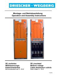
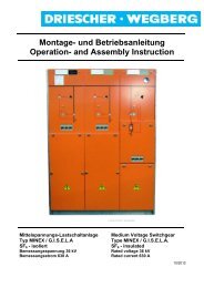
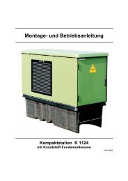
Montage- und Betriebsanleitung Operation- and Assembly Instruction
Montage- und Betriebsanleitung Operation- and Assembly Instruction
Montage- und Betriebsanleitung Operation- and Assembly Instruction

Sie wollen auch ein ePaper? Erhöhen Sie die Reichweite Ihrer Titel.
YUMPU macht aus Druck-PDFs automatisch weboptimierte ePaper, die Google liebt.
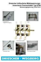
Anhang B<br />
Deaktivierung der Sicherungsauslösung<br />
Die Sicherungsauslösung der Transformatorschaltfelder<br />
ist im Auslieferungszust<strong>and</strong> der Schaltanlagen<br />
aktiviert.<br />
Zur Deaktivierung der Sicherungsfreiauslösung können<br />
folgende Einzelteile einfach entfernt werden.<br />
Im Einzelnen sind dies drei Teile:<br />
� Auslösehebel<br />
� Haltebolzen<br />
� Befestigungsclip<br />
Gehen Sie wie folgt vor:<br />
Die <strong>Montage</strong> muss bei ausgeschaltetem<br />
Lasttrennschalter durchgeführt werden, um<br />
Verletzungen <strong>und</strong> Fehlschaltungen zu vermeiden!<br />
- Schalten Sie den Lasttrennschalter aus <strong>und</strong> den<br />
Erdungsschalter ein.<br />
- Nehmen Sie die Sicherungsabdeckblende ab.<br />
- Entfernen Sie die Frontblende.<br />
- Entfernen Sie den Befestigungsclip <strong>und</strong> anschließend<br />
den Haltebolzen <strong>und</strong> den Auslösehebel.<br />
- Legen Sie die Bauteile für eine spätere Wiederaktivierung<br />
zum Anlagenzubehör.<br />
- Montieren Sie die Frontblende unter Beachtung<br />
der <strong>Montage</strong>hinweise auf dem blauen Hinweisaufkleber.<br />
- Nehmen Sie die Schaltanlage wieder in Betrieb.<br />
Aktivierung der Sicherungsauslösung<br />
Zur Aktivierung der Sicherungsauslösung bauen Sie<br />
die drei Bauteile unter Beachtung der beschriebenen<br />
Arbeitsschritte gemäß den Bildern an den Antrieb an.<br />
Appendix B<br />
DRIESCHER � WEGBERG<br />
Fuse Trip Deactivation<br />
The fuse tripping in the transformer cubicles is activated<br />
in the supply state of the switchgears.<br />
To deactivate the fuse tripping, the following parts<br />
can easily be removed.<br />
In detail, these are three components:<br />
� actuation lever<br />
� holding bolt<br />
� fixation clip<br />
Proceed as follows:<br />
The assembly has to be performed with<br />
switch-disconnector switches OFF, to avoid<br />
injuries <strong>and</strong> switching errors.<br />
- Switch OFF the switch-disconnector <strong>and</strong> switch<br />
ON the earthing switch.<br />
- Remove the fuse cover.<br />
- Remove the front cover.<br />
- Remove the fixation clip <strong>and</strong> then the holding<br />
bolt <strong>and</strong> the actuation lever.<br />
- Put the components to the switchgear accessories<br />
for a later reactivating.<br />
- Install the front cover <strong>und</strong>er consideration of the<br />
installation hints on the blue hint sticker.<br />
- Set the switchgear to work again.<br />
Activation of the fuse tripping<br />
To activate the fuse tripping install the three components<br />
to the mechanism <strong>und</strong>er consideration of the<br />
described work steps according to the pictures.<br />
MINEX / G.I.S.E.L.A 51