Montage- und Betriebsanleitung Operation and Assembly Instructions
Montage- und Betriebsanleitung Operation and Assembly Instructions
Montage- und Betriebsanleitung Operation and Assembly Instructions

Erfolgreiche ePaper selbst erstellen
Machen Sie aus Ihren PDF Publikationen ein blätterbares Flipbook mit unserer einzigartigen Google optimierten e-Paper Software.
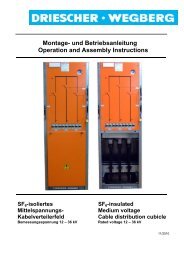
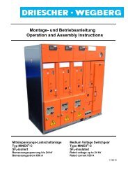
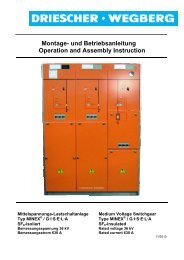
<strong>Montage</strong>- <strong>und</strong> <strong>Betriebsanleitung</strong><br />
<strong>Operation</strong> <strong>and</strong> <strong>Assembly</strong> <strong>Instructions</strong><br />
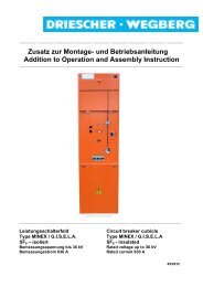
Mittelspannungs-<br />
Lastschaltanlage<br />
Typ LDTM<br />
Luftisoliert<br />
Bemessungsspannung bis 24 kV<br />
Bemessungsstrom 630 A<br />
Medium Voltage Switchgear<br />
Type LDTM<br />
Air-insulated<br />
Rated voltage up to 24 kV<br />
Rated current 630 A<br />
07/2001
DRIESCHER • WEGBERG<br />
2<br />
LDTM
Für diese Druckschrift behalten wir uns alle Rechte vor. Mißbräuchliche<br />
Verwendung, wie insbesondere Vervielfältigung<br />
<strong>und</strong> Weitergabe an Dritte, ist - auch auszugsweise - nicht gestattet.<br />
Angaben <strong>und</strong> Abbildungen unverbindlich. Änderungen<br />
vorbehalten.<br />
DRIESCHER • WEGBERG, 2001<br />
DRIESCHER • WEGBERG<br />
We reserve all rights for this publication. Misuse, especially duplication<br />
<strong>and</strong> transfer to third parties is prohibited, even in case of<br />
excepts. Text <strong>and</strong> illustrations are not binding. We reserve the<br />
right to make revisions.<br />
DRIESCHER • WEGBERG, 2001<br />
LDTM 3
DRIESCHER • WEGBERG<br />
INHALT<br />
INHALT.............................................................................4<br />
ALLGEMEINES ................................................................5<br />
BESTIMMUNGSGEMÄßE VERWENDUNG ..........................5<br />
NORMEN UND VORSCHRIFTEN ......................................5<br />
BETRIEBSBEDINGUNGEN .............................................6<br />
HAFTUNGSBESCHRÄNKUNGEN ......................................6<br />
GEWÄHRLEISTUNG.......................................................7<br />
KUNDENDIENST............................................................8<br />
SICHERHEITSVORSCHRIFTEN......................................9<br />
ALLGEMEINES ..............................................................9<br />
HANDHABUNG............................................................10<br />
ARBEITEN AN MITTELSPANNUNGS-<br />
SCHALTANLAGEN .......................................................11<br />
FÜNF SICHERHEITSREGELN ........................................12<br />
SICHERHEITSHINWEISE FÜR TRANSPORT,<br />
MONTAGE, BETRIEB UND WARTUNG ...........................13<br />
BESCHREIBUNG ...........................................................14<br />
ALLGEMEINES ............................................................14<br />
STÖRLICHTBOGENBEGRENZER....................................15<br />
ÜBERSICHT................................................................16<br />
TECHNISCHE DATEN....................................................17<br />
BEMESSUNGSGRÖßEN................................................17<br />
HH-SICHERUNGSEINSÄTZE.........................................17<br />
ABMESSUNGEN UND GEWICHTE..................................18<br />
MONTAGE......................................................................20<br />
ABLADEN UND TRANSPORTIEREN................................20<br />
AUFSTELLEN DER SCHALTANLAGE ..............................21<br />
KUPPELN DER AUSLÖSEWELLEN DES<br />
STÖRLICHTBOGENBEGRENZER BEI<br />
EINZELFELDLIEFERUNG ..............................................25<br />
ANSCHLUß.................................................................26<br />
BETRIEB ........................................................................28<br />
INBETRIEBNAHME .......................................................28<br />
SCHALTVORGÄNGE ....................................................30<br />
SCHALTEN DES LASTTRENNSCHALTERS ......................30<br />
SCHALTEN DES ERDUNGSSCHALTERS .........................32<br />
AUSTAUSCH DER HH-SICHERUNGSEINSÄTZE ..............33<br />
MAßNAHMEN NACH AUSLÖSUNGEN DURCH DEN<br />
STÖRLICHTBOGENSENSOR .........................................34<br />
ISOLIERENDE SCHUTZPLATTE (ZUBEHÖR) ...................34<br />
KAPAZITIVE SCHNITTSTELLE (OPTION) ........................35<br />
MOTORANTRIEB (OPTION) ..........................................37<br />
MAGNETAUSLÖSER (OPTION) .....................................39<br />
KURZSCHLUßANZEIGER (OPTION) ...............................39<br />
INSTANDHALTUNG.......................................................40<br />
WARTUNG .................................................................40<br />
HINWEISE AUS DER PRAXIS.........................................41<br />
PRÜFEN DER SCHALTANLAGE .....................................41<br />
FEHLERBEHEBUNG .....................................................42<br />
ANHANG A.....................................................................43<br />
LDTM-SCHALTANLAGEN OHNE<br />
STÖRLICHTBOGENBEGRENZER....................................43<br />
4<br />
LDTM<br />
CONTENS<br />
CONTENS................................................................ 3<br />
GENERAL INFORMATION...................................... 4<br />
USE AS INTENDED ...............................................4<br />
STANDARDS AND SPECIFICATIONS ........................4<br />
SERVICE CONDITIONS .......................................... 5<br />
RESTRICTIONS ON RELIABILITY.............................5<br />
WARRANTY.........................................................6<br />
CUSTOMER SERVICE............................................7<br />
SAFETY REGULATIONS ........................................ 8<br />
GENERAL INFORMATION.......................................8<br />
HANDLING...........................................................9<br />
WORKING ON MEDIUM VOLTAGE SWITCHGEAR.....10<br />
FIVE SAFETY RULES...........................................11<br />
SAFETY INSTRUCTIONS FOR TRANSPORT,<br />
ASSEMBLY OPERATION AND MAINTENANCE .......12<br />
DESCRIPTION ....................................................... 13<br />
GENERAL..........................................................13<br />
ARC LIMITING DEVICE.........................................14<br />
OVERAL VIEW....................................................15<br />
TECHNICAL DATA................................................ 16<br />
RATED VALUES..................................................16<br />
HV HRC FUSES................................................16<br />
DIMENSIONS AND WEIGHTS ................................17<br />
ASSEMBLY............................................................ 19<br />
DISCHARGE AND TRANSPORT ............................19<br />
INSTALLATION OF THE SWITCHGEAR....................20<br />
COUPLING THE TRIP SHAFT OF THE ARC LIMTING<br />
DEVICE IN CASE OF SINGLE CUBICLES...............24<br />
CONNECTION ...................................................25<br />
OPERATION .......................................................... 27<br />
SETTING TO WORK.............................................27<br />
SWITCHING OPERATIONS ...................................29<br />
SWITCHING OF THE SWITCH -DISCONNECTOR......29<br />
SWITCHING OF THE EARTHING SWITCH................31<br />
REPLACEMENT OF THE HV HRC FUSES .............32<br />
MEASURES AFTER AN ACTIVATION BY MEANS OF<br />
THE SENSOR...................................................33<br />
INSULATING BARRIER (ACCESSORY) ...................33<br />
CAPACITY INTERFACE (OPTION) .........................34<br />
MOTOR DRIVE (OPTION) ....................................36<br />
TRIP COIL (OPTION)...........................................38<br />
SHORT CIRCUIT DISPLAY (OPTION).....................38<br />
MAINTENANCE ..................................................... 39<br />
SERVICING........................................................39<br />
PRACTICAL HINTS..............................................40<br />
TESTING OF THE SWITCHGEAR ...........................40<br />
RESOLVING PROBLEMS ..................................... 41<br />
ANNEX A ............................................................... 42<br />
LDTM SWITCHGEAR WITHOUT ARC LIMTING<br />
DEVICE...........................................................42
Allgemeines<br />
Bestimmungsgemäße Verwendung<br />
Die DRIESCHER- LDTM-Schaltanlage ist eine<br />
typgeprüfte Mittelspannungs-Schaltanlage für Innenraumanwendung<br />
mit Mehrzwecklasttrennschaltern.<br />
Die Löschkammern des Schaltgerätes<br />
arbeiten als geschlossenes System nach dem<br />
Hartgas-Prinzip.<br />
Die Mittelspannungs-Schaltanlage vom Typ LDTM<br />
ist ausschließlich zum Schalten <strong>und</strong> Verteilen<br />
elektrischer Energie mit Strömen bis 630 A bei<br />
Spannungen bis 24 kV, 50/60 Hz bestimmt.<br />
Eine <strong>and</strong>ere oder darüber hinausgehende Verwendung<br />
gilt als nicht bestimmungsgemäß. Für<br />
hieraus resultierende Schäden haftet der Hersteller<br />
nicht.<br />
Das Risiko trägt allein der Betreiber/Benutzer.<br />
Normen <strong>und</strong> Vorschriften<br />
Vorschrift der Berufsgenossenschaft<br />
BGV A1 (VBG1) Allgemeine Vorschriften<br />
BGV A2 (VBG4) Elektrische Anlagen <strong>und</strong> Betriebsmittel<br />
DIN/VDE-Bestimmungen<br />
DIN VDE 0101 Errichten von Starkstromanlagen<br />
mit Nennspannungen<br />
über 1 kV.<br />
DIN VDE 0105 Betrieb von elektrischen Anlagen.<br />
VDE 0670 Teil 2 Wechselstromtrennschalter<br />
Erdungsschalter.<br />
VDE 0670 Teil 4 Hochspannungssicherungen.<br />
VDE 0670 Teil 6 Metallgekapselte Wechselstrom-Schaltanlagen<br />
für Bemessungsspannungen<br />
über<br />
1kV bis einschließlich 52 kV.<br />
VDE 0670 Teil 301 Hochspannungs-Lastschalter.<br />
VDE 0670 Teil 303 Hochspannungs-Lastschalter-<br />
Sicherungs-Kombination.<br />
VDE 0670 Gemeinsame Bestimmungen<br />
Teil 1000 für Hochspannungs-Schaltgeräte-Normen.<br />
VDE 0682 Teil 415 Spannungsprüfsysteme<br />
(Entwurf)<br />
DRIESCHER • WEGBERG<br />
General Information<br />
Use as Intended<br />
The switchgear DRIESCHER-LDTM is a tested<br />
medium voltage switchgear for indoor applications<br />
with general purpose switches. The arcing<br />
chambers of the switches are working like the<br />
principle of hard-gas in a closed system.<br />
The medium voltage switchgear of LDTM type<br />
was exclusively designed for the distribution of<br />
electric energy with currents up to 630 A <strong>and</strong><br />
voltages of up to 24 kV, 50/60 Hz.<br />
Another or an extended use is not considered as<br />
a use according to its purpose. The producer<br />
does not guarantee for damages resulting from it.<br />
The risk is exclusively in the h<strong>and</strong>s of the user.<br />
St<strong>and</strong>ards <strong>and</strong> Specifications<br />
Specifications of the German Trade Association<br />
BGV-A1 (VBG1) General specifications<br />
BGV-A2 (VBG4) Electrical systems <strong>and</strong><br />
equipment<br />
St<strong>and</strong>ards<br />
DIN VDE 0101 Power installations exceeding<br />
AC 1kV.<br />
EN 50110-1 <strong>Operation</strong> of electrical installations.<br />
IEC 60129 Alternating current disconnectors<br />
<strong>and</strong> earthing switches.<br />
IEC 60282-1 High voltage fuses.<br />
IEC 60298 A.C metal-enclosed<br />
switchgear <strong>and</strong> controlgear<br />
for rated voltages above 1kV<br />
<strong>and</strong> up to <strong>and</strong> including<br />
52kV<br />
IEC 60265-1 High-voltage switchgear<br />
IEC 60420 High-voltage alternating current<br />
switch-fuse combinations<br />
IEC 60694 Common specifications for<br />
high-voltage switchgear <strong>and</strong><br />
controlgear st<strong>and</strong>ards.<br />
IEC 61243-5 Voltage detecting systems<br />
LDTM 5
DRIESCHER • WEGBERG<br />
Betriebsbedingungen<br />
Normale Betriebsbedingungen<br />
Die Schaltanlage ist für normale Betriebsbedingungen<br />
von Innenraum-Schaltgeräten <strong>und</strong> Schaltanlagen<br />
bei folgenden Umgebungstemperaturen<br />
ausgelegt:<br />
Höchstwert +60 °C *<br />
Tiefstwert -25 °C<br />
Sonder-Betriebsbedingungen<br />
Nach VDE 0670 Teil 1000 können von den normalen<br />
Betriebsbedingungen abweichende Betriebsbedingungen<br />
zwischen Hersteller <strong>und</strong> Betreiber<br />
vereinbart werden. Zu jeder Sonder-<br />
Betriebsbedingung muß der Hersteller vorher befragt<br />
werden.<br />
Hinweis zu etwaigen klimatischen Sonder-<br />
Betriebsbedingungen:<br />
Beim Betrieb von Schaltanlagen in Gebieten mit<br />
hoher Luftfeuchte <strong>und</strong>/oder starken kurzzeitigen<br />
Temperaturschwankungen besteht die Gefahr von<br />
häufigen Tauniederschlägen. Zur Vermeidung<br />
unzulässiger Kondensationserscheinungen <strong>und</strong><br />
sich dadurch möglicherweise ergebender Korrosion<br />
sind in Absprache mit dem Hersteller Gegenmaßnahmen<br />
(z.B. elektrische Heizung) zu ergreifen.<br />
Haftungsbeschränkungen<br />
Alle in dieser <strong>Montage</strong>- <strong>und</strong> <strong>Betriebsanleitung</strong> enthaltenen<br />
technischen Informationen, Daten <strong>und</strong><br />
Hinweise für die Installation, Bedienung <strong>und</strong> Wartung<br />
der Schaltanlage entsprechen dem St<strong>and</strong> der<br />
Drucklegung <strong>und</strong> erfolgen unter Berücksichtigung<br />
unserer bisherigen Erfahrungen <strong>und</strong> Erkenntnisse<br />
nach bestem Wissen.<br />
Für etwaige Fehler oder Unterlassungen haften wir<br />
unter Ausschluß weiterer Ansprüche im Rahmen<br />
der im Hauptvertrag eingegangenen Gewährleistungsverpflichtungen.<br />
Ansprüche auf Schadensersatz,<br />
gleich aus welchem Rechtsgr<strong>und</strong> derartige<br />
Ansprüche hergeleitet werden, sind ausgeschlossen,<br />
soweit sie nicht auf Vorsatz oder grober<br />
Fahrlässigkeit beruhen.<br />
* bei Umgeungstemperaturen > 40°C Reduktionsfaktoren berücksichtigen<br />
6<br />
LDTM<br />
Service <strong>Instructions</strong><br />
St<strong>and</strong>ard service conditions<br />
The switchgear are designed for normal service<br />
conditions of indoor switchgear <strong>and</strong> switching systems<br />
at the following ambient temperatures:<br />
Maximum value + 60°C *<br />
Lowest value -25°C<br />
Special Operating Conditions<br />
In accordance with IEC 60694, the manufacturer<br />
<strong>and</strong> the owner can agree to operating conditions<br />
that deviate from the st<strong>and</strong>ard conditions. The<br />
manufacturer must be asked in advance about<br />
any special service condition.<br />
Note on eventual Climatic Special Operating<br />
conditions<br />
If switchgear are operated in areas with a high air<br />
humidity <strong>and</strong>/or strong, rapid temperature oscillations,<br />
there is the danger of frequent dew precipitations:<br />
To avoid inadmissible condensation<br />
phenomena <strong>and</strong> the resulting corrosion the relative<br />
preventive measures have to be agreed with<br />
the producer (i.e. electric heating).<br />
Restrictions on Liability<br />
All of the technical information, data <strong>and</strong> notes<br />
about the installation, operation <strong>and</strong> maintenance<br />
of the medium voltage switchgear contained<br />
in these <strong>Operation</strong> <strong>and</strong> <strong>Assembly</strong> <strong>Instructions</strong><br />
are current as of the day of printing<br />
<strong>and</strong> are stated to the best of our knowledge on<br />
the basis of our experience <strong>and</strong> know-how.<br />
We accept liability for any errors or omissions,<br />
to the exclusion of further claims, within the<br />
scope of the agreed warranty. Claims for compensation<br />
for damage are excluded, regardless<br />
of the legal basis for those claims, unless they<br />
are the result of intent or gross negligence.<br />
Translations are made to the best of knowledge.<br />
Liability of any kind shall therefore not be<br />
accepted for faults made in the translation even<br />
if the operating instructions are translated by us<br />
or by a third party. Solely the Germany textwhich<br />
can be made available on request-shall<br />
prevail.<br />
* at ambient temperatures > 40°C take care of the reduction factors
Gewährleistung<br />
Diese <strong>Montage</strong>- <strong>und</strong> <strong>Betriebsanleitung</strong> enthält alle<br />
erforderlichen Hinweise <strong>und</strong> ist vor Inbetriebnahme<br />
der Schaltanlage sorgfältig durchzulesen.<br />
Für Schäden <strong>und</strong> Betriebsstörungen, die sich aus<br />
der Nichtbeachtung der <strong>Montage</strong>- <strong>und</strong> <strong>Betriebsanleitung</strong><br />
ergeben, übernehmen wir keine Haftung.<br />
Gewährleistungsansprüche sind sofort nach der<br />
Feststellung des Mangels unter Angabe der Auftragsnummer<br />
schriftlich anzumelden.<br />
Die Gewährleistung erlischt bei:<br />
- unsachgemäßer Beh<strong>and</strong>lung,<br />
- nicht bestimmungsgemäßer Verwendung,<br />
- unzulässigen Betriebsmitteln,<br />
- fehlerhafter Aufstellung,<br />
- falschem oder nicht fachgemäßem Anschluß<br />
der Mittelspannungskabel bzw. der Hilfs-/<br />
Steuerleitungen.<br />
Driescher-HH-Sicherungen, Zubehör <strong>und</strong> Ersatzteile<br />
sind speziell konstruiert <strong>und</strong> in aufwendigen<br />
Testreihen erprobt worden.<br />
Wir weisen ausdrücklich darauf hin, daß nicht vom<br />
Hersteller gelieferte Ersatzteile sowie die vom Hersteller<br />
empfohlenen Zubehörteile auch nicht vom<br />
Hersteller freigegeben sind. Der Einbau <strong>und</strong> die<br />
Verwendung von Fremdprodukten kann unter Umständen<br />
konstruktiv vorgegebene Eigenschaften<br />
der Produkte negativ verändern <strong>und</strong> die Sicherheit<br />
für Person, Schaltanlage oder <strong>and</strong>ere Sachwerte<br />
beeinträchtigen. Vor Einbau von Fremdprodukten<br />
ist die schriftliche Genehmigung des Herstellers<br />
erforderlich.<br />
Für Schäden, die aus der ungenehmigten Verwendung<br />
von Fremdprodukten resultieren sowie sich<br />
aus eigenmächtigen Veränderungen oder Umbauten<br />
an unseren Produkten oder Zubehör ergeben,<br />
ist jede Haftung des Herstellers ausgeschlossen.<br />
Gewährleistungsdauer<br />
Die Gewährleistung dauert 12 Monate ab Auslieferung.<br />
Warranty<br />
DRIESCHER • WEGBERG<br />
These <strong>Operation</strong> <strong>and</strong> <strong>Assembly</strong> <strong>Instructions</strong><br />
contain all required notes <strong>and</strong> must be read<br />
through carefully before placing the medium voltage<br />
switchgear into service.<br />
We accept no liability for damage <strong>and</strong> operational<br />
disruptions resulting from failure to comply with<br />
the <strong>Operation</strong> <strong>and</strong> <strong>Assembly</strong> <strong>Instructions</strong>.<br />
Claims <strong>und</strong>er the warranty must be reported in<br />
writing, complete with the contract number, immediately<br />
after the defect is discovered.<br />
The warranty is render null <strong>and</strong> void in the<br />
event of:<br />
- improper h<strong>and</strong>ling<br />
- use not as intended<br />
- impermissible equipment<br />
- faulty erection<br />
- incorrect or nonprofessional connection of<br />
medium voltage cables or the auxiliary/control<br />
lines<br />
Driescher HV H.R.C. fuses, accessories <strong>and</strong> replacement<br />
parts are specially constructed <strong>and</strong> tested<br />
in time-consuming test series. We expressly<br />
point out that replacement parts not supplied by<br />
the manufacturer <strong>and</strong> the accessory parts not recommended<br />
by the manufacturer are also not<br />
approved by the manufacturer. Installing <strong>and</strong><br />
using third-party products may negatively affect<br />
structurally specified properties of products <strong>and</strong><br />
may impair the safety of persons, switchgear or<br />
other material resources. The written approval of<br />
the manufacturer is required before installing<br />
third-party products.<br />
The manufacturer assumes absolutely no liability<br />
for damage resulting from the unapproved use of<br />
third-party products or arbitrary changes or conversions<br />
of our products or accessories.<br />
Duration of Warranty<br />
The warranty is valid for 12 months starting with<br />
delivery.<br />
LDTM 7
DRIESCHER • WEGBERG<br />
K<strong>und</strong>endienst<br />
Für sämtliche technischen Auskünfte über<br />
DRIESCHER-Produkte <strong>und</strong> deren systemtechnische<br />
Anwendungen steht Ihnen unser K<strong>und</strong>endienst<br />
zur Verfügung.<br />
Treten Schwierigkeiten an unseren Produkten auf,<br />
wenden Sie sich bitte an die zuständige Vertretung<br />
oder an das Herstellerwerk.<br />
Geben Sie bitte bei Rückfragen oder Ersatzteilbestellungen<br />
folgende auf dem Typenschild angegebene<br />
Daten an:<br />
� Schaltanlagentyp<br />
� Auftragsnummer,<br />
� Fabrikationsnummer,<br />
� Baujahr,<br />
� Bemessungsspannung <strong>und</strong> Bemessungsstrom.<br />
Durch Angabe dieser Daten ist gewährleistet, daß<br />
Ihnen die richtigen Informationen oder die benötigten<br />
Ersatzteile zugehen.<br />
Fritz Driescher KG<br />
Spezialfabrik für<br />
Elektrizitätswerksbedarf GmbH & Co.<br />
Postfach 1193<br />
41837 Wegberg; Deutschl<strong>and</strong><br />
Industriestraße 2<br />
41844 Wegberg; Deutschl<strong>and</strong><br />
Telefon 02434 81-1<br />
Telefax 02434 81446<br />
www.driescher-wegberg.de<br />
e-mail:info@driescher-wegberg.de<br />
Technische Änderungen im Rahmen der Weiterentwicklung der<br />
in dieser <strong>Montage</strong>- <strong>und</strong> <strong>Betriebsanleitung</strong> beh<strong>and</strong>elten Schaltanlage<br />
behalten wir uns vor. Aus den Angaben, Abbildungen<br />
<strong>und</strong> Beschreibungen dieser <strong>Montage</strong>- <strong>und</strong> <strong>Betriebsanleitung</strong><br />
können daher keine Ansprüche hergeleitet werden.<br />
8<br />
Customer Service<br />
Our Customer Service is at your disposal for all<br />
technical information regarding DRIESCHER products<br />
<strong>and</strong> their systems engineering applications.<br />
If difficulties with our products arise, please contact<br />
the responsible representative or the manufacturing<br />
factory.<br />
If you have any questions or if you wish to order<br />
replacement parts, please specify the following<br />
data shown on the nameplate:<br />
� type of switch<br />
� job number<br />
� serial number<br />
� model year<br />
� rated voltage <strong>and</strong> rated current value<br />
Specifying these items ensures that you will receive<br />
the correct information or required replacement<br />
parts.<br />
Fritz Driescher KG<br />
Spezialfabrik für<br />
Elektrizitätswerksbedarf GmbH & Co.<br />
Postfach 1193<br />
41837 Wegberg, Germany<br />
Industriestrasse 2<br />
41844 Wegberg, Germany<br />
Tel.: +49 2434 811<br />
Fax: +49 2434 81 446<br />
www.driescher-wegberg.de<br />
e-mail:info@driescher-wegberg.de<br />
We reserve the right to make technical changes during the<br />
further development of the switchgear discussed in these <strong>Instructions</strong><br />
for <strong>Operation</strong>. Consequently, no claims can be based<br />
on the data, illustrations <strong>and</strong> descriptions in these <strong>Instructions</strong><br />
for <strong>Operation</strong>.<br />
LDTM
Sicherheitsvorschriften<br />
Allgemeines<br />
Die in der <strong>Montage</strong>- <strong>und</strong> <strong>Betriebsanleitung</strong> enthaltenen<br />
Hinweise zu<br />
- Transport<br />
- <strong>Montage</strong><br />
- Inbetriebnahme<br />
- Bedienung<br />
- Wartung<br />
der Mittelspannungs-Schaltanlage müssen unbedingt<br />
beachtet werden.<br />
Wichtige sicherheitstechnische Hinweise, sind<br />
durch folgende Symbole gekennzeichnet.<br />
Warnung vor einer Gefahrenstelle !<br />
Warnung vor elektrischer Spannung !<br />
Weist auf Richtlinien <strong>und</strong> Vorschriften hin !<br />
Diese Symbole finden Sie bei allen Hinweisen in<br />
dieser <strong>Montage</strong>- <strong>und</strong> <strong>Betriebsanleitung</strong>, bei denen<br />
Gefahr für Leib <strong>und</strong> Leben besteht.<br />
Befolgen Sie diese Hinweise, um Unfälle <strong>und</strong> Beschädigungen<br />
der Mittelspannungs-Schaltanlage<br />
zu vermeiden. Neben diesen Hinweisen sind<br />
- Sicherheitsvorschriften,<br />
- Unfallverhütungsvorschriften,<br />
- Richtlinien <strong>und</strong> anerkannte Regeln der Technik<br />
sowie sämtliche Instruktionen dieser <strong>Montage</strong>- <strong>und</strong><br />
<strong>Betriebsanleitung</strong> zu beachten !<br />
DRIESCHER • WEGBERG<br />
Safety Regulations<br />
General Information<br />
It is imperative that the notes in these Operating<br />
<strong>Instructions</strong> regarding<br />
- transport<br />
- assembly<br />
- putting into service<br />
- operation<br />
- maintenance jobs<br />
of the medium voltage switchgear be adhered to.<br />
Important instructions such as safety notes are<br />
identified by means of the following symbols.<br />
Warning of a danger area !<br />
Warning of electrical voltage !<br />
Refers to guidelines <strong>and</strong> specifications !<br />
You will find these symbols with all notes in these<br />
Operating <strong>and</strong> <strong>Assembly</strong> <strong>Instructions</strong>, which prevent<br />
damage to the switchgear or endangerment of persons.<br />
Follow these notes to avoid accidents <strong>and</strong> damage<br />
involving the medium voltage switchgear. Aside from<br />
these notes, comply with<br />
- safety specifications<br />
- accident prevention regulations<br />
- guidelines <strong>and</strong> recognized rules of technology<br />
as well as all instructions <strong>and</strong> notes in these <strong>Operation</strong><br />
<strong>and</strong> <strong>Assembly</strong> <strong>Instructions</strong>.<br />
LDTM 9
DRIESCHER • WEGBERG<br />
H<strong>and</strong>habung<br />
Diese <strong>Montage</strong>- <strong>und</strong> <strong>Betriebsanleitung</strong> soll dem<br />
Betreiber/Bediener das sichere <strong>und</strong> sachgerechte<br />
Arbeiten sowie die Wartung der Mittelspannungs-<br />
Schaltanlage erleichtern.<br />
Jede Person, die mit Transport, Installation, Inbetriebnahme,<br />
Bedienung <strong>und</strong> Wartung der Mittelspannungs-Schaltanlage<br />
beauftragt ist, muß<br />
- die <strong>Montage</strong>- <strong>und</strong> <strong>Betriebsanleitung</strong>,<br />
- die Sicherheitsvorschriften <strong>und</strong> die Sicherheitshinweise<br />
der einzelnen Kapitel <strong>und</strong> Abschnitte<br />
gelesen <strong>und</strong> verst<strong>and</strong>en haben.<br />
Um Bedienungsfehler zu vermeiden <strong>und</strong> einen<br />
störungsfreien Betrieb der Mittelspannungs-<br />
Schaltanlage zu gewährleisten, muß die <strong>Montage</strong><strong>und</strong><br />
<strong>Betriebsanleitung</strong> dem Betreiber/Bediener<br />
stets zugänglich sein.<br />
Neben dieser <strong>Montage</strong>- <strong>und</strong> <strong>Betriebsanleitung</strong>, den<br />
Sicherheitsvorschriften <strong>und</strong> den Texten, die durch<br />
Sicherheitssymbole gekennzeichnet sind, sind<br />
folgende allgemeine Vorschriften für die H<strong>and</strong>habung<br />
der Mittelspannungs-Schaltanlage bindend:<br />
- Anschlußbedingungen der örtlichen Energieversorgungsunternehmen<br />
(EVU),<br />
- Europäische Sicherheitsvorschriften (EU-<br />
Norm) „Sicherheit von Maschinen, Geräten<br />
<strong>und</strong> Anlagen“<br />
- In Ländern außerhalb der EU die entsprechenden<br />
Sicherheitsvorschriften<br />
10<br />
LDTM<br />
H<strong>and</strong>ling<br />
These <strong>Operation</strong> <strong>and</strong> <strong>Assembly</strong> <strong>Instructions</strong> should<br />
make it easier for the owner/operator to perform the<br />
work safely <strong>and</strong> properly <strong>and</strong> to carry out the maintenance<br />
on the medium voltage switchgear.<br />
Everyone assigned transport, installation, commissioning,<br />
operation <strong>and</strong> maintenance duties on the<br />
medium voltage switchgear must have read <strong>and</strong><br />
<strong>und</strong>erstood<br />
- the <strong>Operation</strong> <strong>and</strong> <strong>Assembly</strong> <strong>Instructions</strong><br />
- the safety regulations <strong>and</strong> the safety notes in<br />
the individual chapters <strong>and</strong> sections.<br />
To avoid operator errors <strong>and</strong> to ensure troublefree<br />
operation of the medium voltage switchgear, the<br />
<strong>Operation</strong> <strong>and</strong> <strong>Assembly</strong> <strong>Instructions</strong> must always<br />
be accessible to the owner/operator.<br />
Aside from these <strong>Operation</strong> <strong>and</strong> <strong>Assembly</strong> <strong>Instructions</strong>,<br />
the safety regulations <strong>and</strong> the texts identified by<br />
safety symbols, the following general specifications<br />
are binding for h<strong>and</strong>ling the medium voltage<br />
switchgear:<br />
- connection conditions of your local power supply<br />
companies<br />
- European safety regulations (EU st<strong>and</strong>ard)<br />
“Safety of Machines, Devices <strong>and</strong> Systems”<br />
- the pertinent safety regulations in countries outside<br />
of the EU.
Arbeiten an Mittelspannungs-Schaltanlagen<br />
Betrieb, Arbeiten <strong>und</strong> Bedienung an Mittelspannungs-Schaltanlagen<br />
dürfen nur Elektrofachkräfte<br />
(gemäß Definition in VDE 0105) ausführen, unter<br />
Beachtung der jeweils gültigen<br />
- VDE / IEC – Vorschriften<br />
- 5 Sicherheitsregeln nach VDE 0105<br />
- Sicherheitsvorschriften<br />
- Unfallverhütungsvorschriften<br />
Bedien- <strong>und</strong> Zubehörteile müssen jederzeit für die<br />
Elektrofachkraft vorh<strong>and</strong>en, zugänglich <strong>und</strong> in<br />
ordnungsgemäßem Zust<strong>and</strong> sein. Sie dürfen keine<br />
Beschädigungen aufweisen.<br />
Ersetzen Sie beschädigte Bedien- <strong>und</strong> Zubehörteile<br />
durch geprüfte oder zugelassene<br />
DRIESCHER- Teile.<br />
Zuständigkeiten <strong>und</strong> Bedienungsabläufe für Bedienung<br />
<strong>und</strong> Wartung müssen geregelt sein <strong>und</strong><br />
eingehalten werden.<br />
Elektrofachkraft<br />
Als Elektrofachkraft laut VDE 0105 gilt, wer auf<br />
Gr<strong>und</strong> seiner fachlichen Ausbildung, Kenntnisse<br />
<strong>und</strong> Erfahrungen sowie Kenntnisse der einschlägigen<br />
Bestimmungen die ihm übertragenen Arbeiten<br />
beurteilen <strong>und</strong> mögliche Gefahren erkennen kann.<br />
Die Elektrofachkraft muß von dem für die<br />
Sicherheit der Schaltanlage Verantwortlichen<br />
berechtigt sein, die jeweils erforderlichen<br />
Arbeiten <strong>und</strong> Tätigkeiten auszuführen.<br />
DRIESCHER • WEGBERG<br />
Work on Medium Voltage Switchgear<br />
Only qualified electrical technicians (as per definition<br />
in EN 50110-1) are permitted to put into<br />
service, work on or operate medium voltage<br />
switchgear, in each case in compliance with the<br />
pertinent valid<br />
- IEC regulations<br />
- 5 safety rules as per the EN 50110-1<br />
- safety regulations<br />
- accident prevention regulations.<br />
Operating <strong>and</strong> accessory parts must always be<br />
available for <strong>and</strong> accessible to the qualified electrical<br />
technician <strong>and</strong> must be in proper condition.<br />
They are not to exhibit any damage.<br />
Replace damaged operating <strong>and</strong> accessory parts<br />
by tested or approved DRIESCHER parts.<br />
Responsibilities <strong>and</strong> operating sequences for<br />
operation <strong>and</strong> maintenance must be regulated<br />
<strong>and</strong> must be adhered to.<br />
Qualified electrical technicians<br />
According to EN 50110-1, a qualified electrical<br />
technician is a person who can evaluate the work<br />
assigned to him (or her) <strong>and</strong> can recognize possible<br />
damages on the basis of his (or her) technical<br />
training, know-how <strong>and</strong> experience.<br />
The qualified electrical technician must be<br />
authorized by the person responsible for<br />
the safety of the switchgear to perform<br />
the work<br />
LDTM 11
DRIESCHER • WEGBERG<br />
Fünf Sicherheitsregeln<br />
1. Freischalten<br />
Kabelfelder <strong>und</strong> Sicherungsfelder der Schaltanlage<br />
an denen gearbeitet wird, mit zugehörigen<br />
Schaltern beidseitig freischalten !<br />
2. Gegen Wiedereinschalten sichern<br />
Abgrenzen des Arbeitsbereichs (z.B. durch<br />
Flaggen <strong>und</strong> Absperrseile mit Warnschildern),<br />
um Verwechslungen mit unter Spannung stehenden<br />
Schaltfeldern auszuschließen !<br />
Hinweisschilder an den freigeschalteten Feldern<br />
anbringen:<br />
- Was wurde freigeschaltet<br />
- Gr<strong>und</strong> der Freischaltung<br />
- Wer hat freigeschaltet<br />
Durch geeignete Verriegelung (z.B. Vorhängeschloß)<br />
das Wiedereinschalten verhindern !<br />
3. Spannungsfreiheit prüfen<br />
Spannungsprüfer auf einw<strong>and</strong>freie Funktion<br />
prüfen <strong>und</strong> die Spannungsfreiheit feststellen !<br />
4. Erden <strong>und</strong> Kurzschließen<br />
Mit Hilfe des Erdungsschalters bzw. mit Erdungs-<br />
<strong>und</strong> Kurzschließvorrichtung über Erdungsbolzen<br />
die jeweiligen Kabelenden erden<br />
<strong>und</strong> kurzschließen !<br />
5. Benachbarte, unter Spannung stehende<br />
Teile abschranken oder abdecken<br />
Bei Innenraum-Schaltanlagen ohne Trennwände<br />
die Arbeitsstellen von den angrenzenden<br />
Schaltfeldern durch geeignete Abgrenzungen<br />
(z.B. Trennwände) absperren !<br />
Gefahren bei Nichtbeachtung der Sicherheitshinweise<br />
Die Nichtbeachtung der Sicherheitshinweise führt<br />
zur Gefährdung von Personen <strong>und</strong> zur Beschädigung<br />
der Schaltanlage.<br />
Dies führt zum Verlust jeglicher Schadensersatzansprüche<br />
<strong>und</strong> kann folgendes nach sich ziehen:<br />
- Versagen wichtiger Funktionen der Schaltanlage,<br />
- Versagen vorgeschriebener Methoden zur<br />
Wartung <strong>und</strong> Inst<strong>and</strong>haltung,<br />
- Verletzung von Personen durch gefährliche<br />
elektrische Spannungen<br />
12<br />
LDTM<br />
Five Safety Rules<br />
1. Isolate<br />
Isolate the cable cubicles <strong>and</strong> transformer<br />
cubicles where the work is being performed<br />
with corresponding switches.<br />
2. Secure against switchgear being reclosed<br />
Separate the working range (i.e. by using<br />
flags <strong>and</strong> closing ropes with warning plates),<br />
to exclude confusions with cubicles<br />
which are still <strong>und</strong>er voltage !<br />
Set up an information sign on the disabled<br />
cubicles, indicating:<br />
- what was isolated,<br />
- reason for the isolating<br />
- name of the person who isolated<br />
Secure the switchgear in a suitable manner<br />
(e.g., padlock the drive) to prevent them<br />
from being turned back on.<br />
3. Check absence of voltage<br />
Check to make certain that the voltage tester<br />
is functioning properly <strong>and</strong> that there is<br />
no voltage present.<br />
4. Earth <strong>and</strong> short-circuit<br />
Using the earthing switch or an earthing<br />
<strong>and</strong> short-circuiting device, earth <strong>and</strong> shortcircuit<br />
the pertinent cable ends via shortcircuit<br />
bolts.<br />
5. Set up barriers aro<strong>und</strong> neighbouring<br />
parts that are live or cover them up.<br />
On indoor switchgears without division<br />
walls limit the working areas from the<br />
nearby switching cubicles by adequate divisions,<br />
i.e. separation walls!<br />
Risks if safety instructions are not complied<br />
with<br />
Failure to observe the safety notes leads to endangerment<br />
of persons <strong>and</strong> damage to the<br />
switchgear. This will culminate in the loss of any<br />
<strong>and</strong> all claims for compensation for damage<br />
<strong>and</strong> may cause the following:<br />
- injury of persons due to dangerous electrical<br />
voltage<br />
- failure of important functions of the<br />
switchgear<br />
- failure of specified methods of maintenance<br />
<strong>and</strong> service.
Sicherheitshinweise für Transport,<br />
<strong>Montage</strong>, Betrieb <strong>und</strong> Wartung<br />
Der Betreiber sorgt dafür, daß alle Transport-,<br />
<strong>Montage</strong>-, Bedienungs- <strong>und</strong> Wartungsarbeiten von<br />
Elektrofachkräften ausgeführt werden, welche die<br />
<strong>Montage</strong>- <strong>und</strong> <strong>Betriebsanleitung</strong> gelesen <strong>und</strong> verst<strong>and</strong>en<br />
haben.<br />
Beachten Sie die Sicherheitshinweise für das Heben<br />
<strong>und</strong> Transportieren der Schaltanlage!<br />
- Hebezeug, Lastaufnahmemittel <strong>und</strong> Anschlagmittel<br />
mit ausreichender Tragfähigkeit verwenden.<br />
- Anschlagmittel nur an den hierfür vorgesehenen<br />
Stellen anschlagen.<br />
- Seile, Ketten oder <strong>and</strong>ere Anschlagmittel müssen<br />
mit Sicherheitshaken ausgerüstet sein.<br />
- Keine angerissenen oder angescheuerten<br />
Seile verwenden.<br />
- Seile <strong>und</strong> Ketten nicht knoten <strong>und</strong> nicht an<br />
scharfen Kanten anlegen.<br />
- Lasten nicht über Personen hinweg heben.<br />
DRIESCHER • WEGBERG<br />
Safety instructions for transport, assembly,<br />
operation <strong>and</strong> maintenance<br />
The owner must make certain that all transport,<br />
operation <strong>and</strong> maintenance jobs are carried out<br />
by qualified electrical technicians who have read<br />
<strong>and</strong> <strong>und</strong>erstood the Operating <strong>Instructions</strong>.<br />
Respect the safety rules for the lifting <strong>and</strong> the<br />
transport of the switchgear!<br />
- Use a lifting device, transport <strong>and</strong> fixation<br />
means with a sufficient load capacity.<br />
- Fix the fixation means only on the prescribed<br />
points.<br />
- Ropes, chains or other fixation means<br />
have to be equipped with safety hooks.<br />
- Do not use damaged or worn ropes.<br />
- Do not knit together ropes <strong>and</strong> chains<br />
<strong>and</strong> do not fix them on sharp angles.<br />
- Do not lift loads over the heads of persons.<br />
LDTM 13
DRIESCHER • WEGBERG<br />
Beschreibung<br />
Allgemeines<br />
Die DRIESCHER – Schaltanlage Typ LDTM ist für<br />
eine Innenraumaufstellung vorgesehen.<br />
Die Schaltanlage ist bei Umgebungstemperaturen<br />
von –25 °C bis 60 °C * einsetzbar.<br />
Durch integrierte Störlichtbogenbegrenzer wird ein<br />
Höchstmaß an passiver <strong>und</strong> aktiver Sicherheit<br />
erreicht.<br />
Die Schaltanlage ist aus Einzel-Schaltfeldern aufgebaut.<br />
Die Schaltfelder können mit Mehrzweck-<br />
Lasttrennschaltern, kurzschlußeinschaltfesten<br />
Erdungsschaltern <strong>und</strong> HH-Sicherungen ausgerüstet<br />
werden.<br />
Aus einzelnen Feldern baukastenartig zusammengesetzt,<br />
kann die Anlage beliebig kombiniert <strong>und</strong><br />
später erweitert werden. Die LDTM – Schaltanlage<br />
ist gr<strong>und</strong>sätzlich für alle Arten von Stationsräumen<br />
geeignet, z.B. für Keller-, Garagen-, Kunststoff-,<br />
Beton-, Turm- <strong>und</strong> Stahlblechstationen.<br />
Neben Kabel- <strong>und</strong> Trafofelder sind für LDTM –<br />
Anlagen Leistungsschalter-, Meß- <strong>und</strong> Übergabefelder<br />
lieferbar.<br />
Zur Beobachtung der Schaltgeräte sind Sichtfenster<br />
vorgesehen.<br />
Die Verschließung der Frontblenden erfolgt mit<br />
Schnellverschlüssen.<br />
Der Türanschlag kann je nach Bedarf links- bzw.<br />
rechtsseitig eingerichtet <strong>und</strong> nachträglich geändert<br />
werden.<br />
* bei Umgeungstemperaturen > 40°C Reduktionsfaktoren berücksichtigen<br />
14<br />
LDTM<br />
Description<br />
General<br />
The Driescher switchgear type LDTM was designed<br />
for all types of indoor applications.<br />
The switchgear is suitable for ambient temperatures<br />
of –25°C up to +60°C *<br />
The integrated arc limiting device gives a<br />
maximum of the passive <strong>and</strong> active safety.<br />
The switchgear is a building of single cubicles.<br />
The cubicles can be equipped with general purpose<br />
switches, short-circuit-poof earthing<br />
switches <strong>and</strong> HRC-fuses.<br />
With its modular composition of single cubicles<br />
the switchgear can be constructed in any combination<br />
<strong>and</strong> subsequently extended. The<br />
LDTM switchgear is principally designed for any<br />
type of rooms in power stations, i.e. for cellar,<br />
garage, plastics, concrete, tower <strong>and</strong> steel lamination<br />
stations.<br />
In addition to the cable- <strong>and</strong> transformer cubicles,<br />
circuit breaker cubicles, measuring cubicles<br />
<strong>and</strong> transfer panels are available.<br />
For the observation of the switching appliances<br />
windows are foreseen.<br />
The locking of the front cover is performed by<br />
quick release locks.<br />
The door stroke can be on the left or on the<br />
right h<strong>and</strong> according to the needs <strong>and</strong> can be<br />
subsequently changed.<br />
* at ambient temperatures > 40°C take care of the reduction factor
Störlichtbogenbegrenzer<br />
LDTM – Schaltanlagen sind st<strong>and</strong>ardmäßig mit<br />
Störlichtbogenbegrenzer ausgerüstet.<br />
Hierzu ist ein Drucksensor im Dach von jedem<br />
Schaltfeld angeordnet, der auf eine in der Rückw<strong>and</strong><br />
angebrachten Auslösewelle wirkt.<br />
Diese Kombination ist ebenfalls in Schaltfelder ohne<br />
aktiven Erdungsschalter (z.B. Transformatorfelder<br />
usw. ) eingebaut.<br />
Die einzelnen Auslösewellen werden mitein<strong>and</strong>er<br />
verb<strong>und</strong>en <strong>und</strong> wirken auf die vorgespannten Erdungsschalterantriebe,<br />
die im Störlichtbogenfall die<br />
Erdungsschalter der Einspeisefelder zuschalten.<br />
Durch die Auslösung des Erdungsschalters wird<br />
der Störlichtbogenfehler in einen galvanischen<br />
Kurzschluß umgew<strong>and</strong>elt – der Störlichtbogen<br />
verlöscht.<br />
Die Funktion des Drucksensors ist nur<br />
dann gewährleistet, wenn der Abst<strong>and</strong><br />
zwischen dem Dach der Schaltanlage <strong>und</strong><br />
der Stationsdecke mindestens 50 mm<br />
beträgt.<br />
Die manuelle EIN- <strong>und</strong> AUS-Schaltung kann bei<br />
vorgespanntem Antrieb wie üblich vorgenommen<br />
werden. Lasttrennschalter <strong>und</strong> Erdungsschalter<br />
können gegenein<strong>and</strong>er verriegelt sein. Die Verriegelung<br />
läßt allerdings die EIN-Schaltung des Erdungsschalters<br />
zur Störlichtbogenbegrenzung<br />
unabhängig vom Schaltzust<strong>and</strong> der Gesamtanlage<br />
zu. Die zur Betätigung der in den Kabelfeldern<br />
vorgespannten Erdungsschalterantriebe benötigte<br />
Auslösewelle ist über Kupplungen aus einzelnen<br />
Wellenabschnitten aufgebaut. Dieser Modulaufbau<br />
der Schaltanlage erlaubt ohne größeren Aufw<strong>and</strong><br />
eine Erweiterung der Schaltanlage. Der Ansprechdruck<br />
des Drucksensors liegt in sicherem Abst<strong>and</strong><br />
unterhalb des Berstdrucks der äußeren Kapselung.<br />
Hinweise zu Kupplung der Auslösewellen Siehe 25<br />
DRIESCHER • WEGBERG<br />
Arc limiting devices<br />
As a st<strong>and</strong>ard the LDTM switchgears have an<br />
arc-limiting device.<br />
There are integrated pressure sensors in the roof<br />
which work on tripping shaft in the back wall of<br />
every cubicle<br />
This combination is also integrated in cubicles<br />
without an active earthing switch ( i.e. transformer<br />
cubicles etc.)<br />
The single tripping shafts are being connected<br />
<strong>and</strong> work onto the preset drives of the earthing<br />
switches. In case of an arc fault the earthing<br />
switches of the incoming cubicles are actuated.<br />
By the activation of the earthing switch the arc<br />
fault is transformed into a galvanic short circuit<br />
<strong>and</strong> the arc is extinguished.<br />
The function of the pressure sensor is<br />
only given, when the space between the<br />
roof of the switchgear <strong>and</strong> the ceiling of<br />
the room is minimum 50mm.<br />
The manual activation <strong>and</strong> disactivation of a preset<br />
drive can be performed as usual. Switchdisconnectors<br />
<strong>and</strong> earthing switches can be interlocked.<br />
The locking, however, permits the activation<br />
of the earthing switch for the arc-limiting<br />
device independently from the switching state of<br />
the whole switchgear. The tripping shaft for acting<br />
the preloaded drives of the earthing switches<br />
in the cable cubicles is made of single shaft<br />
parts, which can be coupled. This modular construction<br />
of the switchgear permits a simple extension<br />
of the switchgear. The reactive pressure<br />
of the pressure sensor is in a safe distance below<br />
the burst pressure of the enclosure.<br />
LDTM 15
DRIESCHER • WEGBERG<br />
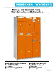
Übersicht<br />
1<br />
13<br />
10<br />
2<br />
3<br />
13<br />
8<br />
14<br />
1. Typenschild<br />
2. Sichtscheibe<br />
3. Blindschaltbild mit Schaltstellungsanzeigen.<br />
4. Schaltstellungsanzeige für Lasttrennschalter<br />
5. Antriebsbuchse für Lasttrennschalter<br />
6. Schaltstellungsanzeige für Erdungsschalter.<br />
7. Antriebsbuchse für Erdungsschalter.<br />
8. Kabelschaltfeld<br />
9. Transformatorschaltfeld<br />
10. Einschubführung für isolierende Schutzplatte<br />
11. Beschriftungsschild.<br />
12. Feldbezeichnungsnummern (ab 5 Felder)<br />
13. Kurzschlußanzeiger (Option)<br />
14. Meßbuchsen mit Schutzstöpsel für kapazitive<br />
Spannungsanzeige bzw. Phasenvergleich<br />
(Option)<br />
16<br />
LDTM<br />
Overall View<br />
1 1 2 2 3 3 4<br />
1. type label<br />
2. window<br />
3. blind diagram with switch position display<br />
4. position display of switch-disconnector<br />
5. drive socket for switch-disconnector<br />
6. position display of earthing switch<br />
7. drive socket for earthing switch<br />
8. Cable cubicle<br />
9. transformer cubicle<br />
10. Insert guide for insulating plate.<br />
11. label<br />
12. type label of cubicle (more than 5 cubicles)<br />
13. short circuit display (option)<br />
14. measuring sockets for the capacitive voltage<br />
indication <strong>and</strong> the phase comparison<br />
(Option)<br />
11<br />
12<br />
5<br />
6<br />
7<br />
9
Technische Daten<br />
Bemessungsgrößen<br />
Bemessungsspannung 12 kV 17,5 kV 24 kV<br />
Bemessungsstrom 630 A 630 A 630 A<br />
Bemessungs-Kurzzeitstrom 20 kA 20 kA 16 kA<br />
Bemessungs-Einschaltstrom 50 kA 50 kA 40 kA<br />
Bemessungs-Lastausschaltstrom 630 A 630 A 630 A<br />
Bemessungs-Ringausschaltstrom 630 A 630 A 630 A<br />
Bemessungs- Kabel- <strong>und</strong><br />
Freileitungsausschaltstrom<br />
Bemessungs – Ausschaltstrom<br />
unter Erdschlußbedingungen<br />
Bemessungs-Stehblitzstoßspannung<br />
Bemessungs – Transformatorausschaltstrom<br />
25 A 25 A 25 A<br />
300 A 300 A 300 A<br />
75/85 kV 95/110 kV 125/145 kV<br />
10 A 10 A 10 A<br />
DRIESCHER • WEGBERG<br />
Technical Data<br />
Rated values<br />
Rated voltage<br />
Rated current<br />
Rated short-time current<br />
Rated short-circuit making<br />
current<br />
Rated mainly active load<br />
breaking current<br />
Rated closed loop breaking<br />
current<br />
Rated cable <strong>and</strong> linecharging<br />
breaking current<br />
Rated breaking current<br />
<strong>und</strong>er earth leakage condition<br />
Rated lightning impulse<br />
withst<strong>and</strong> voltage<br />
Rated no-load transformer<br />
breaking current<br />
Zul. Umgebungstemperaturen - 25°C - + 60°C* Ambient temperatures<br />
* bei Umgebungstemperaturen > 40°C Reduktionsfaktoren berücksichtigen<br />
HH-Sicherungseinsätze<br />
Die Tabelle gibt Absicherungsempfehlungen für<br />
DRIESCHER HH-Sicherungseinsätze<br />
Trafo-Bemessungsleistung/<br />
Rated transformer-power<br />
[kVA]<br />
7,2 kV<br />
e=292 mm<br />
min/max.<br />
Bei Absicherung von Transformatoren mit einer Bemessungs-<br />
Leistung von >1000kVA <strong>und</strong> ≤ 2000kVA sind <strong>and</strong>ere Sicherungs-Baugrössen<br />
erforderlich. Bitte nehmen Sie Rücksprache<br />
mit der Fa. DRIESCHER.<br />
* at ambient temperatures > 40°C take care of the reduction factor<br />
HV HRC fuses<br />
The table gives safety recommendations for<br />
the DRIESCHER HV HRC fuses.<br />
Sicherungsbemessungsstrom [A]<br />
Rated current of HRC Fuses<br />
Bemessungsspannung<br />
12 kV<br />
e=292 mm<br />
min/max.<br />
17,5 kV<br />
e=442 mm<br />
min/max.<br />
24 kV<br />
e=442 mm<br />
min/max.<br />
50 10/16 6,3/10 6,3 6,3<br />
75 16/25 10/16 6,3/10 6,3<br />
100 16/25 16/25 10/16 6,3/10<br />
125 25/40 16/25 10/16 10<br />
160 25/40 16/40 16/25 10/16<br />
200 40/63 25/40 16/25 10/16<br />
250 40/63 31,5/40 25/40 16/25<br />
315 63/100 40/63 25/40 25/40<br />
400 63/100 40/63 31,5/40 25/40<br />
500 80/160 50/100 40/63 31,5/40<br />
630 100/200 63/100 40/63 31,5/63<br />
800 125/200 80 63/100 40/63<br />
1000 160/200 100 63/125 40/100<br />
e = Sicherungsstichmaß/reference measure of the HRC fuse<br />
If transformers are secured with a rated power of<br />
> 1000kVA <strong>und</strong> ≤ 2000kVA other sizes for the fuses<br />
are necessary. Please contact Messrs. Driescher.<br />
LDTM 17
DRIESCHER • WEGBERG<br />
Abmessungen <strong>und</strong> Gewichte<br />
Schaltfeld 12 kV z.B. Transformatorschaltfeld<br />
Abmessungen Kabelanschluß Gewichte<br />
X Y Z<br />
Kabelschaltfeld 1142 366 500 ca. 145 kg<br />
Trafoschaltfeld 700 366 500 ca. 149 kg<br />
Kabelschaltfeld 1142 366 750 ca. 177 kg<br />
Trafoschaltfeld 700 366 750 ca. 181 kg<br />
18<br />
1900<br />
728<br />
A<br />
248 248<br />
14x25<br />
48 400 48<br />
Z<br />
Schnitt A-A<br />
Z<br />
611 58<br />
58<br />
A<br />
LDTM<br />
Dimensions <strong>and</strong> Weights<br />
Cubicle 12kV i.e. transformer cubicle<br />
Y<br />
Measurements cable connection weights<br />
X Y Z<br />
Cable cubicle 1142 366 500 ca. 145 kg<br />
Transformer<br />
cubicle<br />
700 366 500 ca. 149 kg<br />
Cable cubicle 1142 366 750 ca. 177 kg<br />
Transformer<br />
cubicle<br />
700 366 750 ca. 181 kg<br />
X
Schaltfeld 24 kV z.B. Kabelschaltfeld<br />
1900<br />
1003<br />
A<br />
4<br />
373 373<br />
14x25<br />
48 650 48<br />
Schnitt A-A<br />
Abmessungen Kabelanschluß Gewichte<br />
X Y Z<br />
Kabelschaltfeld 1142 366 750 ca. 195 kg<br />
Trafoschaltfeld 700 366 750 ca. 216 kg<br />
Kabelschaltfeld 1142 366 900 ca. 206 kg<br />
Trafoschaltfeld 700 366 900 ca. 227 kg<br />
Z<br />
746<br />
886<br />
58<br />
58<br />
A<br />
DRIESCHER • WEGBERG<br />
Cubicle 24kV i.e. cable cubicle<br />
Y<br />
X<br />
Measurements cable connection weights<br />
X Y Z<br />
Cable cubicle 1142 366 750 ca. 195 kg<br />
Transformer<br />
cubicle<br />
700 366 750 ca. 216 kg<br />
Cable cubicle 1142 366 900 ca. 206 kg<br />
Transformer<br />
cubicle<br />
700 366 900 ca. 227 kg<br />
LDTM 19
DRIESCHER • WEGBERG<br />
<strong>Montage</strong><br />
20<br />
Erdungsschalter müssen aus Sicherheitsgründen<br />
während des Transports <strong>und</strong><br />
während der <strong>Montage</strong> in EIN - Stellung bleiben!<br />
Bringen Sie vor der Inbetriebnahme<br />
alle Erdungsschalter mit der Schaltkurbel in<br />
AUS – Stellung .<br />
Abladen <strong>und</strong> Transportieren<br />
Beachten Sie die Sicherheitshinweise <strong>und</strong> Unfallverhütungsvorschriften<br />
!<br />
Beachten Sie, daß die Schaltanlage nicht<br />
liegend auf der Rückw<strong>and</strong> transportiert<br />
werden darf !<br />
Verwenden sie zum Heben<br />
<strong>und</strong> Trans-portieren<br />
der Schaltanlage Hebezeug,Lastaufnahmemittel<br />
<strong>und</strong> Anschlagmittel<br />
mit ausreichender<br />
Kraft.<br />
Befestigen Sie Anschlagmittel<br />
nur an den<br />
vorgesehenen Kranungsvorrichtungen<br />
- Abladen <strong>und</strong> Transportieren der Schaltanlage<br />
mit Kran oder Hubstapler.<br />
- Anschlagen der Anschlagmittel mit Sicherheitshaken<br />
nur an den kopfseitig angebrachten<br />
Kranungsvorrichtungen.<br />
- Benutzen Sie Anschlagmittel mit gleicher Länge.<br />
Der Winkel darf einen Wert von 90° nicht<br />
überschreiten.<br />
- Achten Sie auf gleichmäßige Gewichtsverteilung!<br />
Nach dem Abladen<br />
- die Schaltanlage auf Beschädigungen prüfen,<br />
- das Zubehör laut Lieferschein auf Vollständigkeit<br />
kontrollieren.<br />
Dokumentieren <strong>und</strong> melden Sie Transportschäden<br />
sofort dem Spediteur <strong>und</strong> der Firma DRIESCHER.<br />
1 1 2 2 3 3<br />
LDTM<br />
<strong>Assembly</strong><br />
For safety reasons the earthing switches<br />
must be in ON-position at the time of<br />
transport <strong>and</strong> working! Setup all earthing<br />
switches in OFF-position via switch crank,<br />
when the switchgear is set into work!<br />
Discharge <strong>and</strong> Transport<br />
Respect the safety hints <strong>and</strong> the anti-accident regulations!<br />
Please observe that the switchgear cannot<br />
be transported lying on the rear wall.<br />
For the lifting <strong>and</strong> the<br />
transport of the switchgear<br />
please use a lifting<br />
device, a load absorption<br />
device <strong>and</strong> a fixing<br />
device with a sufficient<br />
force.<br />
Fix the fixation means<br />
only on the predisposed<br />
lifting devices.<br />
- Discharge <strong>and</strong> transport of the switchgear<br />
with a crane or a lifting carriage.<br />
- Fixation of the fixation means with safety<br />
hooks only on the lifting device at top of<br />
the switchgear.<br />
- Use fixing means of the same length.<br />
The angle must not exceed a value of<br />
90°.<br />
- Please provide for an equal weight balance.<br />
After discharge:<br />
- Check the switchgear for damages.<br />
- Control, if according to the delivery note<br />
the accessories are complete.<br />
Document <strong>and</strong> signal transport damages immediately<br />
to the carrier <strong>and</strong> to DRIESCHER.
Aufstellen der Schaltanlage<br />
Platzbedarf<br />
Platzbedarf der Schaltanlage entnehmen Sie dem<br />
Kapitel Abmessungen <strong>und</strong> Gewichte<br />
Maß“L“<br />
Maß„T“<br />
12kV:Anzahl Felder 500mm breit+<br />
Anzahl Felder 750mm breit+<br />
76mm<br />
24kV:Anzahl Felder 750mm breit+<br />
Anzahl Felder 900mm breit+<br />
84mm<br />
12kV: 728mm<br />
24kV: 1003mm<br />
- Achten Sie bei Innenraum-Stationen auf ausreichende<br />
Breite der Gänge <strong>und</strong> Zugangsräume,<br />
um freie Bewegung <strong>und</strong> Transport zu<br />
ermöglichen.<br />
- Mindestbreite des Bedienganges: 800 mm<br />
- Die Mindestbreite des Bedienganges darf<br />
nicht unterschritten bzw. durch in den Gang<br />
hineinragende Teile eingeengt werden.<br />
Stellen Sie die Schaltanlage so auf, daß<br />
- Ausgänge <strong>und</strong> Türen von Innenraumstationen<br />
frei zugänglich sind.<br />
- Fluchtwege innerhalb der Station nicht mehr<br />
als 20 m betragen.<br />
- Stellen Sie die Schaltanlage nicht in explosionsgefährdete<br />
oder staubexplosionsgefährdete<br />
Räume auf.<br />
L<br />
DRIESCHER • WEGBERG<br />
Positioning of the Switchgear<br />
Necessary space<br />
dreifeldige Anlage dargestellt<br />
Please check the space that is needed for the<br />
switchgear in the section on dimensions <strong>and</strong><br />
weights.<br />
measure “L”<br />
measure “T”<br />
12kV:number of cubicles 500mm<br />
width+ number of cubicles<br />
750mm width+ 76mm<br />
24kV:number of cubicles 750mm<br />
width+ number of cubicles<br />
900mm width+ 84mm<br />
12kV: 728mm<br />
24kV: 1003mm<br />
- In case of indoor stations please make sure that<br />
there is a sufficient width between the corridors<br />
<strong>and</strong> the access areas for movement <strong>and</strong> transport.<br />
- Minimum width of the user passage: 800mm<br />
- The minimum width of the user passage must<br />
be respected <strong>and</strong> shall not be narrowed by<br />
parts that extend into the passage<br />
Please position the switchgear in a way that<br />
- exits <strong>and</strong> doors of indoor stations can be easily<br />
accessed;<br />
- flight paths within the station are no more than<br />
20 m.<br />
- Please do not position the switchgear in rooms<br />
exposed to an explosion risk or to a dust explosion<br />
risk.<br />
LDTM 21<br />
T
DRIESCHER • WEGBERG<br />
Befestigung<br />
Stellen Sie die Befestigungspunkte (1) für die<br />
Schaltanlage <strong>und</strong> Bodenaussparung (2) entsprechend<br />
den Maßangaben in Bild 1 <strong>und</strong> Bild 2 her.<br />
Bild 1<br />
Bild 2<br />
Achten Sie je nach Ausführung der Schaltanlage<br />
auf den Mindestw<strong>and</strong>abst<strong>and</strong> (X) zur<br />
Rückw<strong>and</strong>:<br />
• mit Störlichtbogenbegrenzer: 0 mm<br />
• ohne Störlichtbogenbegrenzer:<br />
(siehe Anhang A)<br />
22<br />
X<br />
X<br />
1<br />
Bodenbefestigung<br />
a b c<br />
12 kV 500/750 mm 288/413 mm 611 mm<br />
24 kV 750/900 mm 417/488 mm 886 mm<br />
Stellen Sie die Schaltanlage nur auf ebenen<br />
<strong>und</strong> waagerechten Betonf<strong>und</strong>amenten oder Zwischenrahmen<br />
mit ausreichender Tragfestigkeit auf,<br />
um ein Verspannen der Schaltfelder zu vermeiden.<br />
LDTM<br />
Mounting<br />
Make the fixing points (1) for the switchgear<br />
<strong>and</strong> the floor cut-out (2) as shown in illustration<br />
1 <strong>and</strong> 2.<br />
Illustration 1<br />
14x25<br />
14x25<br />
b a a b<br />
2 500<br />
70<br />
Illustration 2<br />
Look for the model of the switchgear for<br />
the minimum clearance (X) from wall to<br />
rear panel:<br />
• with arc limiting device: 0 mm<br />
• without arc limiting device:<br />
(see attachment A)<br />
c<br />
58.5 58<br />
150+X<br />
70<br />
Base mounting<br />
a b c<br />
12 kV 500/750 mm 288/413 mm 611 mm<br />
24 kV 750/900 mm 417/488 mm 886 mm<br />
Please place the switchgear only on<br />
plain <strong>and</strong> horizontal concrete bases or intermediate<br />
frames with a sufficient carrying capacity<br />
to avoid the deformation of the cubicles.
Aufstellungsempfehlungen<br />
LDTM-Schaltanlagen sind st<strong>and</strong>ardmäßig mit einem<br />
Störlichtbogenbegrenzer ausgerüstet, der<br />
eine raumunabhängige Aufstellung ermöglicht.<br />
Haben Sie eine Schaltanlage ohne Störlichtbogenbegrenzer<br />
erworben, so beachten Sie die besonderen<br />
Hinweise zur Aufstellung in Anhang A.<br />
Berücksichtigen Sie bei der Aufstellung der Schaltanlagen,<br />
das im Falle eines inneren Störlichtbogenfehlers<br />
ein hohes Energiepotential über die<br />
Druckentlastungseinrichtungen freigeben wird, die<br />
Auswirkungen auf die Umgebung haben. Beachten<br />
Sie insbesondere die Druckbelastung des umgebenden<br />
Baukörpers, die vom Ansprechdruck der<br />
Druckentlastungseinrichtung abhängig ist.<br />
Die Druckbelastung kann zu einer Zerstörung der<br />
Gebäudewände führen. Gemauerte Wände haben<br />
nur eine geringe Druckfestigkeit.<br />
DRIESCHER • WEGBERG<br />
Positioning Recommendations<br />
As a st<strong>and</strong>ard LDTM switchgears are equipped<br />
with an arc-fault limiting device that enables a<br />
positioning in any possible space.<br />
Do you have a switchgear without the arc limiting<br />
device, observe the special hints for mounting in<br />
attachment A.<br />
Please observe the environmental effects of the<br />
switchgears that are opened in case of internal<br />
arc faults with a high energy potential via pressure<br />
release devices. Please observe above all<br />
the pressure exposure of the housed building that<br />
depends on the operative pressure of the pressure<br />
release device.<br />
High operative pressures may result in a destruction<br />
of the walls of the building. Brick walls have<br />
only a low resistance against pressure.<br />
LDTM 23
DRIESCHER • WEGBERG<br />
Aufstellen<br />
- Stellen Sie die Schaltanlage mit Kran oder<br />
Hubwagen auf den vorbereiteten Platz. Evtl.<br />
Unebenheiten ausgleichen oder unterlegen.<br />
24<br />
Beachten Sie die Sicherheitshinweise<br />
(Abladen <strong>und</strong> Transportieren)<br />
- Halten Sie die Mindestmaße ein!<br />
- Öffnen Sie die Schaltfeldtüren.<br />
- Drehen Sie die Befestigungsschrauben in die<br />
vorbereiteten Bohrungen ein <strong>und</strong> verschrauben<br />
diese h<strong>and</strong>fest.<br />
- Richten Sie die Schaltanlage horizontal <strong>und</strong><br />
vertikal aus.<br />
Bei Schaltanlagen, die als Einzelfelder<br />
geliefert werden, müssen die Einzelfelder<br />
am Aufstellungsort am vorderen <strong>und</strong><br />
hinteren Längsholm verschraubt werden<br />
(jeweils 5 Schrauben M8).<br />
- Ziehen Sie die Befestigungsschrauben fest.<br />
Bei aufgeständerten Böden mit nicht<br />
verschraubten Bodenplatten muß der<br />
Feldboden mit einer Bodenplatte<br />
verschlossen werden.<br />
- Bei Transport <strong>und</strong> Aufstellen der Anlage darauf<br />
achten, daß der im Anlagendach befindliche<br />
Sensor nicht durch äußere Einwirkungen<br />
ausgelöst wird.<br />
Die einw<strong>and</strong>freie Funktion des Drucksensors<br />
ist nur dann gewährleistet, wenn der<br />
Abst<strong>and</strong> zwischen dem Dach der Schaltanlage<br />
<strong>und</strong> der Stationsdecke mindestens<br />
50 mm beträgt.<br />
Schaltanlage erden<br />
- Verbinden Sie die Erdungsschraube (Gr<strong>und</strong>rahmen<br />
Schaltanlage) mit der Stationserde.<br />
Erdungen in Wechselstromanlagen für<br />
Bemessungspannungen über 1 kV,<br />
Mindestquerschnitte <strong>und</strong> Strombelastbarkeit<br />
von Erdungsleitungen siehe VDE<br />
0101.<br />
LDTM<br />
Installation<br />
- Install the switchgear with a crane or a lifting<br />
carriage on the predetermined site. Level<br />
eventual unevenness or bridge it.<br />
Please observe the safety hints (discharge<br />
<strong>and</strong> transport).<br />
- Please respect the minimum dimensions.<br />
- Open the doors of the cubicles.<br />
- Put the fixation screws into the prepared<br />
holes <strong>and</strong> tighten them.<br />
- Please align the switchgear in the horizontal<br />
<strong>and</strong> the vertical sense.<br />
In the case of switchgears that have to<br />
be supplied as single cubicles the single<br />
cubicles have to be screwed on the installation<br />
site on the front <strong>and</strong> on the<br />
rear longitudinal cross-beam (each time<br />
with 5 M8 screws).<br />
- Tighten the fixation screws.<br />
In the case of rough pavements with<br />
unscrewed plates on the pavement the<br />
bottom of the cubicle has to be closed<br />
with a bottom plate.<br />
- While transporting <strong>and</strong> positioning the<br />
switchgear you should make sure that the<br />
sensor mounted on the roof is not activated<br />
by external influences.<br />
The perfect function of the pressure<br />
sensor is only guaranteed, if the distance<br />
between the roof of the switchgear<br />
<strong>and</strong> the ceiling of the station is at least<br />
50 mm.<br />
Earthing of the Switchgear<br />
- Connect the earthing screw (base frame of<br />
the switchgear) with the earthing of the station.<br />
For earthings in switchgears with AC<br />
<strong>and</strong> for rated voltages higher than 1 KV,<br />
minimum see VDE 0101 regarding<br />
minimum cross sections <strong>and</strong> current capacity<br />
of earthing connections.
Kuppeln der Auslösewellen des Störlichtbogenbegrenzer<br />
bei Einzelfeldlieferung<br />
LDTM – Schaltfelder mit Störlichtbogenbegrenzer<br />
sind unterein<strong>and</strong>er mit je einer Kupplung versehen<br />
(Bild 3).<br />
Bei im Werk komplettierten Anlagen ist die<br />
Welle bereits gekuppelt.<br />
Vor Inbetriebnahme der Schaltanlage ist daher<br />
darauf zu achten, daß die Kupplung der Auslösewellen<br />
zweier benachbarter Schaltfelder funktionstüchtig<br />
ist;<br />
Achten Sie darauf, daß die Auslösewellen<br />
aller Schaltfelder vor Inbetriebnahme gekuppelt<br />
sein müssen, um die Funktion des<br />
Störlichtbogenbegrenzers zu sichern. Für<br />
Schäden <strong>und</strong> Betriebsstörungen, die sich<br />
aus dem Nichtkuppeln der Auslösewellen<br />
ergeben, übernehmen wir keine Haftung!<br />
Nach <strong>Montage</strong> der Schaltanlage Zylinderschraube<br />
des Kuppelteils lösen <strong>und</strong> Kuppelteil nach links in<br />
das benachbarte Schaltfeld schieben (Bild 1).<br />
Kuppelteil über die Auslösewelle bis vor spürbaren<br />
Anschlag schieben, auf Leichtgängigkeit achten,<br />
Zylinderschraube vor der Auslösewelle in Kuppelteil<br />
fest <strong>and</strong>rehen (Bild 2).<br />
Auslösewelle auf Leichtgängigkeit prüfen.<br />
Die Auslösemechanik des Störlichtbogenbegrenzers<br />
wurde im Werk optimal<br />
eingestellt. Nehmen Sie daher keine Veränderungen<br />
an der Aulösemechanik vor, da es<br />
ansonsten zu Fehlverhalten oder Nichtansprechen<br />
führen kann.<br />
Zylinderkopfschraube DIN 912 - M5x20<br />
Sockethead cap screw<br />
Bild 1<br />
Bild 2<br />
DRIESCHER • WEGBERG<br />
Coupling of the Drive Shafts of the Arc<br />
limiting device for Single Field Supplies<br />
LDTM cubicles with an arc limiting device are interlinked<br />
by a coupling (Figure 3).<br />
In case of switchgears that have been<br />
completed in the factory the shaft has already<br />
been coupled.<br />
Before setting to work of the switchgear you should<br />
thus make sure that the coupling of the shafts in<br />
the two nearby switching cubicles are in a perfect<br />
functional state.<br />
Please make sure that the drive shafts of<br />
all cubicles are coupled before the start of<br />
the switchgear to guarantee the operation<br />
of the arc limiting device. For damages <strong>and</strong><br />
troubles during operation that result from<br />
the lacking coupling of the drive shaft we<br />
do not assume any responsibility.<br />
After the assembly of the switchgear loosen the<br />
cylindrical screw of the coupling part <strong>and</strong> move the<br />
coupling part left h<strong>and</strong> into the nearby cubicle<br />
(Figure 1).<br />
Move the coupling part across the drive shaft up to<br />
the sensible stop, provide for an easy gliding <strong>and</strong><br />
tighten the cylindrical screw in front of the drive<br />
shaft in the coupling part (Figure 2).<br />
Check the easy gliding of the drive shaft.<br />
The triggering of the arc limiting device was<br />
adjusted optimal at the factory. Never<br />
change these settings, because mistakes or<br />
not actuating are possible.<br />
Bild 3<br />
LDTM 25
DRIESCHER • WEGBERG<br />
Anschluß<br />
Kabelanschluß<br />
Sämtliche Kabelanschlußstellen sind als Flachanschlüsse<br />
nach DIN 6206 ausgebildet <strong>und</strong> in der<br />
Anschlußzone typgeprüft.<br />
Geeignet sind luftisolierte Innenraum-<br />
Endverschlüsse der verschiedenen Fabrikate in<br />
Verbindung mit Flachkabelschuhen.<br />
Zur Erleichterung der Kabelarbeiten ist das Kabelhalteeisen<br />
verstellbar.<br />
26<br />
Beachten Sie die Sicherheitsvorschriften,<br />
VDE 0105 <strong>und</strong> BGV A2 !<br />
- Erden <strong>und</strong> schließen Sie das anzuschließende<br />
Hochspannungskabel einseitig kurz.<br />
- An der anzuschließenden Schaltanlage:<br />
• Schalten Sie den Lasttrennschalter aus<br />
• Schalten Sie den Erdungsschalter ein<br />
- Schieben Sie eine isolierende Schutzplatte in<br />
die geöffnete Stellung des Lasttrennschalters<br />
ein.<br />
- Phasenfolge:<br />
• L1 links,<br />
• L2 Mitte,<br />
• L3 rechts!<br />
- Öffnen Sie die Schaltfeldtüren. Drehen <strong>und</strong><br />
öffnen Sie dazu den Verschluß gegen den<br />
Uhrzeigersinn.<br />
- Kabelhalteeisen entsprechend des Kabelendverschlusses<br />
einstellen. Bereiten Sie das<br />
Kabelende vor.<br />
• Entsprechendes Kabelende aus dem Kabelkanal<br />
oder Kabelzwischenboden in den<br />
Kabelanschlußraum führen.<br />
• Kabelende nach <strong>Montage</strong>anweisung des<br />
Kabelgarnituren-Herstellers absetzen <strong>und</strong><br />
Kabelgarnitur montieren.<br />
- Montieren Sie die Phase L1 <strong>und</strong> verschrauben<br />
Sie das Kabelhalteeisen so, daß das Kabel<br />
senkrecht nach unten ragt. Montieren Sie dann<br />
Phase L2 <strong>und</strong> zum Schluß Phase L3.<br />
LDTM<br />
Connection<br />
Cable Connection<br />
All the cable connection points were designed as<br />
flat connections according to DIN 6206 <strong>and</strong> the<br />
type was type tested in the connection area.<br />
The most suitable ones are air-insulated indoorterminals<br />
of different trademarks in connections<br />
with flat cable sockets.<br />
To facilitate cable work the cable box carrier is<br />
adjustable.<br />
Respect the safety regulations of EN<br />
50110-1 <strong>and</strong> BGV A2 !<br />
- Gro<strong>und</strong> the high-tension cable <strong>and</strong> cause a<br />
short circuit on one end.<br />
- On the switchgear that shall be connected<br />
• switch off the switch-disconnector,<br />
• switch on the earthing switch.<br />
- Insert an insulating protective plate into the<br />
opened position of the switch-disconnector.<br />
- Sequence of Phases<br />
• L1 left h<strong>and</strong>,<br />
• L2 center,<br />
• L3 right h<strong>and</strong>!<br />
- Open the doors of the cubicles. For this purpose<br />
turn <strong>and</strong> open the locking anticlockwise.<br />
- Adjust the cable box carrier according to the<br />
cable terminals. Prepare the cable ends.<br />
• Lead the relative cable end from the cable<br />
canal or the cable mezzanine into the<br />
cable connection area.<br />
• Prepare the cable end according to the<br />
assembly instructions of the cable producer<br />
<strong>and</strong> assemble the set of cables.<br />
- Assemble phase L1 <strong>and</strong> screw the cable<br />
box carrier in a way that the cable extends<br />
vertically downwards. Assemble phase L2<br />
<strong>and</strong> finally phase L3.
- Überprüfen Sie den Zust<strong>and</strong> der Endverschlüsse,<br />
z.B. Oberflächenbeschaffenheit,<br />
ordnungsgemäße Anordnung der Kabelschuhe<br />
<strong>und</strong> Klemmverbindungen. Bei Kleinendverschlüssen<br />
müssen die Klemmschrauben der<br />
Schlauchschellen nach vorn oder hinten angeordnet<br />
sein.<br />
- Beachten Sie die Sicherheits- <strong>und</strong> <strong>Montage</strong>hinweise<br />
des Herstellers der Kabelgarnituren !<br />
- Befestigen Sie die Endverschlüsse an der<br />
mitgelieferten oder bauseitig angebrachten<br />
Kabelhalteeisen!<br />
- Beachten Sie die Phasenfolge!<br />
- Befestigen Sie die Kabel so an den Anschlußkontakten<br />
des Schaltgerätes, daß keine mechanischen<br />
Spannungen auf die Kontaktanschlußlaschen<br />
einwirken !<br />
DRIESCHER • WEGBERG<br />
- Check the state of the terminals, i.e. the state<br />
of the surfaces, the right fixation of the cable<br />
sockets <strong>and</strong> the clamps. With small terminals<br />
the binding-screws of the tube clamps have<br />
to be disposed in a front or a rear row.<br />
- Respect the safety <strong>and</strong> assembly instructions<br />
of the cable producer.<br />
- Fix the terminals on the supplied cable box<br />
carrier or at site available.<br />
- Respect the sequence of phases.<br />
- Fix the cables in a way that on the connection<br />
contacts of the switches no mechanical<br />
tensions are exercised on the contact connection<br />
flaps.<br />
LDTM 27
DRIESCHER • WEGBERG<br />
Betrieb<br />
Inbetriebnahme<br />
Sicherheitsvorschriften <strong>und</strong> Unfallverhütungsvorschriften<br />
beachten.<br />
<strong>Montage</strong>arbeiten prüfen<br />
Kontrollieren Sie, ob alle <strong>Montage</strong>arbeiten ordnungsgemäß<br />
durchgeführt wurden.<br />
Mechanische Funktionen prüfen<br />
- Schalten Sie den Lasttrennschalter <strong>und</strong> Erdungsschalter<br />
ein/aus.<br />
- Kontrollieren Sie die Schalterstellungsanzeiger<br />
<strong>und</strong> beobachten Sie die Schalterstellung durch<br />
unmittelbare Sichtkontrollle<br />
28<br />
Der Lasttrennschalter läßt sich nur bei<br />
ausgeschaltetem Erdungsschalter schalten<br />
bzw. der Erdungsschalter nur bei ausgeschaltetem<br />
Lasttrennschalter!<br />
- Kontrollieren Sie die HH-Sicherungseinsätze<br />
(siehe Kapitel „Austausch der HH–Sicherungseinsätze“).<br />
Sonstige Kontrollen<br />
- Prüfen Sie die Zusatzeinrichtungen (falls vorh<strong>and</strong>en).<br />
• Anschlußbuchsen für kapazitive Spannungsanzeigegeräte<br />
müssen während des<br />
Betriebes mit Abdeckstopfen oder Anzeigegeräten<br />
ausgerüstet sein.<br />
• Kurzschlußanzeiger zurückstellen.<br />
• Funktion des Motorantriebes bei Lasttrennschalter<br />
- Kombination mit Motorantrieb<br />
prüfen (siehe Kapitel „Option“).<br />
Erden Sie die Kabelfelder oder Sicherungsfelder,<br />
deren Kabelanschlüsse freibleiben<br />
mit zugehörigem Erdungsschalter<br />
(Schalterstellung beachten <strong>und</strong> ggf. durch<br />
Schaltsperre mit Warnschild (Option) sichern).<br />
LDTM<br />
<strong>Operation</strong><br />
Setting to Work<br />
Observe the safety regulations <strong>and</strong> the antiaccident<br />
rules.<br />
Check the assembly operations<br />
Please check, if all the assembly operations<br />
have been correctly performed.<br />
Check the mechanical functions.<br />
- Switch on/off the switch-disconnector <strong>and</strong><br />
the earthing switch.<br />
- Check the switch position display <strong>and</strong><br />
check the switch position by an immediate<br />
visual examination.<br />
The switch-disconnector can be<br />
switched only with a switched off<br />
earthing switch <strong>and</strong> the earthing switch<br />
only with a switched off switchdisconnector.<br />
- Check the HV HRC fuses (see chapter<br />
“Replacement of the HV HRC fuses”).<br />
Further Checks<br />
- Check the additional equipment (if present).<br />
• The connection sockets for capacity<br />
tension displays have to be equipped<br />
during operation with cover taps or display<br />
appliances.<br />
• Reset the short circuit display.<br />
• Check the operation of the motor drive<br />
in case of a combination of the switchdisconnector<br />
with the motor drive (see<br />
“Option” section).<br />
Gro<strong>und</strong> the cable or transformer cubicles<br />
with free cable connections with the relative<br />
earthing switch (observe the switch position<br />
<strong>and</strong> eventually secure it with a lockout device<br />
<strong>and</strong> a warning plate (option).
Bedien- <strong>und</strong> Zubehörteile<br />
- Schaltkurbel (Zubehör) für Erdungsschalter<br />
<strong>und</strong> Lasttrennschalter mit integriertem Schlüssel<br />
für Schnellverschluß<br />
- Bedienungsanleitung<br />
- Spannungsanzeigegerät (Option)<br />
- isolierende Schutzplatte (Zubehör)<br />
müssen im Schaltanlagenraum oder im Nebenraum<br />
übersichtlich <strong>und</strong> griffbereit liegen.<br />
• Hilfs- <strong>und</strong> Steuerspannung zuschalten.<br />
• Alle getroffenen Schutzmaßnahmen wie Kurzschluß-<br />
<strong>und</strong> Erdungsverbindungen so aufheben,<br />
daß keine Gefährdung für Personen <strong>und</strong><br />
Sachen auftritt.<br />
Bedienpersonal unterrichten<br />
Händigen Sie dem Bedienpersonal (Elektrofachkraft)<br />
vor Inbetriebnahme der Schaltanlage die<br />
<strong>Montage</strong>- <strong>und</strong> <strong>Betriebsanleitung</strong> aus. Das Bedienpersonal<br />
muß bei Übernahme der Schaltanlage mit<br />
allen Einzelheiten der Bedienung vertraut sein!<br />
DRIESCHER • WEGBERG<br />
Operative Parts <strong>and</strong> Accessories<br />
- manual crank (Accessories) for earthing<br />
switch <strong>and</strong> switch-disconnector with<br />
integrated key for rapid lock<br />
- manual of usage<br />
- voltage display (option)<br />
- insulating plate (Accessories)<br />
must be present in the room of the switchgear or a<br />
nearby room ready for use.<br />
• Apply the drive tension.<br />
• All the taken protective measures as short<br />
circuit <strong>and</strong> earthing connections have to be<br />
suspended in a way that there is no danger<br />
for persons or objects.<br />
Information of the Operators<br />
Before the start of the switchgear h<strong>and</strong> over the<br />
manual of usage to the operators (electric experts).<br />
At the delivery of the switchgear the operators<br />
must get familiar with all the details of operation.<br />
LDTM 29
DRIESCHER • WEGBERG<br />
Schaltvorgänge<br />
Die Betätigung erfolgt mittels eines Schaltkurbels<br />
(Zubehör) mit integriertem Schlüssel für Schnellverschluß.<br />
Schaltkurbel für Erdungsschalter <strong>und</strong> Lasttrennschalter<br />
mit integriertem Schlüssel für Schnellverschluß<br />
(1):<br />
- Einsteckseite (a) für Schnellverschluß,<br />
- Einsteckseite (b) für Erdungsschalter,<br />
- Einsteckseite (c) für Lasttrennschalter.<br />
Schalterstellungsanzeiger<br />
Die Schalterstellungsanzeiger geben in Verbindung<br />
mit dem Blindschaltbild den Schaltzust<strong>and</strong><br />
von Lasttrennschalter <strong>und</strong> Erdungsschalter an.<br />
30<br />
Vergewissern Sie sich über die tatsächliche<br />
Schalterstellung durch einen Blick<br />
durch die Sichtscheibe<br />
Schalten des Lasttrennschalters<br />
Kabelfeld Typ F<br />
Das Ein- <strong>und</strong> Ausschalten des Lasttrennschalters<br />
erfolgt über eine Schaltkurbel. Die eingebaute<br />
Federsprung – Schaltvorrichtung sorgt für sicheres<br />
Ein- <strong>und</strong> Ausschalten unabhängig von der Bedienungsgeschwindigkeit.<br />
Transformatorfeld Typ SEA<br />
Der Lasttrennschalter mit Freiauslösung Typ SEA<br />
verfügt über einen Federkraftspeicher, der mit dem<br />
Einschalten gespannt wird.<br />
Die Freiauslösung erfolgt<br />
- über HH-Sicherungen mit Schlagstift der Klasse<br />
„mittel“ entsprechend VDE 0670 Teil 4,<br />
- über Auslösemagnet.<br />
b<br />
1<br />
LDTM<br />
Switching <strong>Operation</strong>s<br />
The operations are performed with a switching<br />
crank (Accessories) <strong>and</strong> an integrated key for<br />
rapid locking.<br />
Switching lever for earthing switch <strong>and</strong> switchdisconnector<br />
with integrated key for the rapid lokking<br />
(1):<br />
c<br />
a<br />
- plug-in side (a) for rapid locking<br />
- plug-in side (b) for earthing switch<br />
- plug-in side (c) for switch-disconnector<br />
Switch position indicator<br />
The switch position indicators together with the<br />
mimic diagram show the switch condition of switchdisconnector<br />
<strong>and</strong> earthing switch.<br />
To make sure of the real switch position<br />
take a look trough the window<br />
Switching of the Switch-disconnector<br />
Cable cubicle Type F<br />
The switching on <strong>and</strong> off of the switch-disconnector<br />
is performed by means of a switching crank. The<br />
integrated spring-assisted mechanism provides for<br />
safe switching on <strong>and</strong> off – independently from the<br />
operational speed.<br />
Transformer cubicle Type SEA<br />
The switch-disconnector with free activation type<br />
SEA includes an energy storing device with resort<br />
that is <strong>und</strong>er tension during activation.<br />
The free activation is performed<br />
- by means of HV HRC fuses with striker pin of<br />
the “medium” class according to IEC 60282-1,<br />
- by means of an trip coil.
Betätigung<br />
- Stecken Sie die Schaltkhebel mit der Einsteckseite<br />
(c) in die Antriebsbuchse des Lasttrennschalters.<br />
Das Aufstecken der Schaltkurbel ist nur bei<br />
ausgeschaltetem Erdungsschalter möglich!<br />
Lasttrennschalter einschalten:<br />
Drehen Sie die Schaltkurbel im Uhrzeigersinn.<br />
Schalterstellungsanzeige senkrecht.<br />
Lasttrennschalter ausschalten:<br />
Drehen Sie die Schaltkurbel gegen den Uhrzeigersinn.<br />
Schalterstellungsanzeige waagerecht.<br />
Sichern gegen Wiedereinschalten.<br />
Bringen Sie Antriebsabdeckung (Option) an.<br />
/ON<br />
/OFF<br />
Machen Sie nach einer Freiauslösung des Transformator<br />
– Lasttrennschalters Typ SEA den<br />
Schalter wie folgt einschaltbereit :<br />
- Stecken Sie die Schaltkurbel in die Antriebsbuchse<br />
des Lasttrennschalters,<br />
- Drehen Sie die Schaltkurbel gegen den Uhrzeigersinn<br />
bis zum hörbaren Einrasten in die<br />
Endstellung.<br />
- Der Schalter ist einschaltbereit.<br />
Actuation<br />
DRIESCHER • WEGBERG<br />
- Plug in the switch crank with the plug-in side<br />
(c) into the drive bush of the switchdisconnector.<br />
The plug-in of the crank is possible only<br />
with a switched off earthing switch.<br />
Switching on the switch- disconnector<br />
Turn the switching crank clockwise.<br />
Vertical position of the switch display.<br />
Switching off the switch-disconnector<br />
Turn the switching crank anticlockwise.<br />
Horizontal position of the switch display.<br />
Safeguarding against Reclosing<br />
Cover the drive opening (optional)<br />
After a free actuation of the transformer – switchdisconnector,<br />
type SEA, prepare the switch for a<br />
new ON-operation as follows:<br />
- Plug in the crank into the drive bush of the<br />
switch-disconnector.<br />
- Turn the crank anticlockwise until it audibly<br />
clicks into its end position.<br />
- The switch is ready for operation.<br />
LDTM 31
DRIESCHER • WEGBERG<br />
Schalten des Erdungsschalters<br />
32<br />
Stellen Sie vor dem Einschalten des Erdungsschalters<br />
die Spannungsfreiheit fest.<br />
Der dreipolige Erdungsschalter ist mit einer<br />
Schnelleinschaltung ausgerüstet <strong>und</strong> damit kurzschlußeinschaltfest.<br />
Betätigung<br />
Stecken Sie die Schaltkurbel mit der Einsteckseite<br />
(b) in die Antriebsbuchse des Erdungsschalters.<br />
Das Aufstecken der Schaltkurbel ist nur bei<br />
ausgeschaltetem Lasttrennschalter möglich!<br />
- Erdungsschalter einschalten :<br />
Drehen Sie die Schaltkurbel im Uhrzeigersinn<br />
(Schalterstellungsanzeiger senkrecht).<br />
- Erdungsschalter ausschalten :<br />
Drehen Sie die Schaltkurbel gegen den Uhrzeigersinn<br />
(Schalterstellungsanzeiger waagerecht).<br />
/ON<br />
LDTM<br />
Switching of the earthing switch<br />
Before switching on the earthing switch<br />
make sure that the switchgear is not <strong>und</strong>er<br />
tension.<br />
The three-pole earthing switch is equipped with<br />
a rapid actuation <strong>and</strong><br />
for this reason it resists against short circuits.<br />
Actuation<br />
Insert the switching crank with side (b) into the<br />
drive bush of the earthing switch.<br />
The plug-in of the switching crank is possible<br />
only with a switched off switchdisconnector!<br />
- Switching on the earthing switch:<br />
Turn the crank clockwise (vertical switch<br />
position display).<br />
- Switching off the earthing switch:<br />
Turn the switching crank anticlockwise (horizontal<br />
switch position display).<br />
/ON<br />
OFF/<br />
/ON<br />
/OFF
Austausch der HH-Sicherungseinsätze<br />
Verwenden Sie nur HH-Sicherungseinsätze nach<br />
VDE 0670 Teil 4 mit einem Kappendurchmesser<br />
bis 88 mm. Der Schlagstift der Sicherung muß der<br />
Klasse “mittel” (50N, ≥20mm) nach VDE 670 Teil 4<br />
entsprechen.<br />
Tauschen Sie stets alle Sicherungseinsätze aus,<br />
auch wenn nicht alle geschaltet haben<br />
(Vorschädigungen der Schmelzleiter möglich ).<br />
Tauschen Sie HH-Sicherungseinsätze wie folgt<br />
aus:<br />
- Lasttrennschalter des Sicherungsfeldes<br />
ausschalten <strong>und</strong> gegen Wiedereinschalten<br />
sichern<br />
- Spannungsfreiheit feststellen.<br />
- Erdungsschalter einschalten.<br />
- Mit der einschenkeligen Bedienungszange (1)<br />
(Zubehör: geeignet für Sicherungseinsätze mit<br />
Kappendurchmesser von 40 bis 88 mm) setzen<br />
Sie den HH-Sicherungseinsatz ein oder<br />
nehmen den HH-Sicherungseinsatz heraus.<br />
Sicherungseinsätze können heiß sein!<br />
Beachten Sie bei Transformator-<br />
Lasttrennschalter mit Freiauslösung SEA die<br />
Lage des Schlagstiftes des HH-<br />
Sicherungseinsatzes (Pfeil zeigt nach oben)!<br />
- Verschließen Sie die Tür.<br />
- Schalten Sie den Erdungsschalter aus.<br />
- Schalten Sie den Lasttrennschalter des Sicherungsfeldes<br />
ein.<br />
DRIESCHER • WEGBERG<br />
Replacement of the HV HRC fuses<br />
Please use only HV HRC fuses according to VDE<br />
0670, Part 4, with cap diameters up to 88 mm.<br />
The striker pin of the fuse must be according to the<br />
“medium” class of VDE 0670, Part 4 (50 N, ≥ 20<br />
mm minimum stroke).<br />
Please always replace all fuses, even if not all of<br />
them have blown. (The fuse elements could<br />
probably be damaged)<br />
Replace the HV HRC fuses as follows:<br />
- Switch off the switch-disconnector of the fuse<br />
cubicle <strong>and</strong> secure it against reactivation.<br />
- Make sure that the switchgear is not <strong>und</strong>er<br />
tension.<br />
- Switch on the earthing switch.<br />
- With the single-leg operation pincers (1) (suitable<br />
for fuses with cap diameters from 40 to 88<br />
mm) insert or remove the HV HRC fuse.<br />
The fuses may be hot!<br />
With the transformer – switch-disconnector<br />
with free trip- mechanism type SEA please<br />
observe the position of the striker pin of the<br />
HV HRC fuse (arrow must point upwards).<br />
- Lock the door.<br />
- Switch off the earthing switch.<br />
- The switch-disconnector is ready for operation.<br />
LDTM 33<br />
1
DRIESCHER • WEGBERG<br />
Maßnahmen nach Auslösungen durch<br />
den Störlichtbogensensor<br />
Wird der im Anlagendach befindliche Drucksensor<br />
nach abgeschlossener <strong>Montage</strong>arbeit zur einmaligen<br />
Funktionskontrolle betätigt, so lösen die vorgespannten<br />
Kraftspeicher die Schnellerder in den<br />
Einspeisefeldern aus.<br />
Zur Wiederherstellung der Auslösebereitschaft sind<br />
in den einzelnen Kabelfeldern folgende Maßnahmen<br />
unbedingt notwendig:<br />
- Alle Lasttrennschalter ausschalten.<br />
- Die Antriebswelle aller Erdungsschalters mittels<br />
Schaltkurbel in EIN – Schaltstellung bringen.<br />
- Antriebswelle der Erdungsschalters mittels<br />
Schaltkurbel in AUS – Stellung bringen.<br />
- Die Erder sind ausgeschaltet <strong>und</strong> die<br />
Kraftspeicher vorgespannt <strong>und</strong> somit wieder<br />
auslösebereit.<br />
Hinweis:<br />
Die manuelle EIN- <strong>und</strong> AUS-Schaltung kann trotz<br />
des vorgespannten Antriebes wie üblich vorgenommen<br />
werden.<br />
Isolierende Schutzplatte (Zubehör)<br />
Zur Sicherung des Kabelanschlußraumes gegen<br />
den Sammelschienenraum läßt sich eine isolierende<br />
Schutzplatte nach VDE 0670 Teil 6 einbringen.<br />
Die isolierende Schutzplatte ist bei geöffnetem<br />
Lasttrennschalter <strong>und</strong> geschlossener Zellentür<br />
einzuschieben.<br />
Dazu die isolierende Schutzplatte von oben angewinkelt<br />
in den Schlitz zwischen Oberblende <strong>und</strong><br />
Türe einführen <strong>und</strong> ganz einschieben (Markierung<br />
beachten)<br />
34<br />
LDTM<br />
Measures after an Activation by means<br />
of the Sensor of the arc limting device<br />
If the pressure sensor positioned on the roof of the<br />
switchgear is activated once after the assembly<br />
work in occasion of a functional check, the pretensioned<br />
energy storing device activates the rapid<br />
earthing switches in the supply fields.<br />
Important: For a reset the following measures have<br />
to be taken in the single cable cubicles:<br />
- Put off all the switch-disconnectors.<br />
- Put on all the drive shaft of the earthing<br />
switches by means of the lever.<br />
- Put the drive shaft of the earthing switches into<br />
the OFF position by means of the lever.<br />
- The earthing switches are in OFF-position now<br />
<strong>and</strong> the pre-tensioned energy storing device<br />
thus ready for use.<br />
Note:<br />
The manual switching from ON to OFF can be<br />
performed as usual despite of the preset drive.<br />
Insulating barrier (Accessories)<br />
To safeguard the cable connection area against<br />
the bus bar section an insulating barrier according<br />
to IEC 60298 can be mounted.<br />
The insulating barrier has to be inserted with an<br />
open switch-disconnector <strong>and</strong> closed cubicle door.<br />
For this scope the insulating barrier is completely<br />
introduced from above in an angle into the slot<br />
between the upper blend <strong>and</strong> the door (observe<br />
the marking).
Kapazitive Schnittstelle (Option)<br />
Spannungsfreiheit feststellen über die kapazitive<br />
Schnittstelle nach VDE 0682 Teil 415<br />
Die Prüfung auf Spannungsfreiheit nach HR-<br />
System (70...90 V am Meßpunkt bei 2,5 µA) erfolgt<br />
mit kapazitiven Spannungsanzeigegeräten an den<br />
Meßbuchsen L1, L2, L3.<br />
Benutzen Sie nur Prüfgeräte nach VDE<br />
0682 Teil 415 (Entwurf) für HR-Systeme.<br />
Beachten Sie die <strong>Montage</strong>- <strong>und</strong> <strong>Betriebsanleitung</strong><br />
der Prüfgerätehersteller <strong>und</strong> VDE<br />
0682 Teil 415 (Entwurf). Prüfen Sie die<br />
Prüfgeräte vor Gebrauch auf Funktion!<br />
- Schutzstöpsel entfernen<br />
- Spannungsanzeigegerät nach <strong>Montage</strong>- <strong>und</strong><br />
<strong>Betriebsanleitung</strong> des Herstellers mit Meßbuchsen<br />
verbinden <strong>und</strong> auf Spannungsfreiheit<br />
prüfen.<br />
- Nach der Prüfung Spannungsanzeigegerät von<br />
den Meßbuchsen trennen.<br />
- Schutzstöpsel auf Meßbuchsen stecken um<br />
das Verschmutzen der Meßbuchsen zu verhindern.<br />
Keine Kurzschlußstecker verwenden ! Die<br />
Schutzfunktion der spannungsbegrenzenden<br />
Sollbruchstelle wird bei Verwendung<br />
von Kurzschlußsteckern unwirksam !<br />
Funktionsprüfung: siehe Skizze auf nachfolgender<br />
Seite. Bei bekannter Betriebsspannung U.<br />
Wiederholungsprüfung: In festen Zeitabständen<br />
durch o.g. Funktionsprüfung bei bekannter Betriebsspannung.<br />
(Letzte Wiederholungs- / Funktionsprüfung<br />
siehe Aufdruck am Koppelteil).<br />
DRIESCHER • WEGBERG<br />
Capacitive Interface (option)<br />
With the capacitive interface check, if the switchgear<br />
is not <strong>und</strong>er tension, see IEC 61243-5.<br />
The check, if the switchgear is not <strong>und</strong>er voltage<br />
(70…90 V at the measuring point with 2,5 µA) is<br />
performed with capacitive voltage display devices<br />
on the measuring bushes L1, L2, L3.<br />
Please only use test appliances corresponding<br />
to IEC 61243-5 for HR Systems.<br />
Observe the operating manual of the producer<br />
of the test appliances <strong>and</strong> IEC<br />
61243-5. Check the test appliances for<br />
proper operation before usage!<br />
- Remove the protective taps.<br />
- Connect the tension display device according<br />
to the operating manual of the producer with<br />
the measuring bushes <strong>and</strong> check, if the<br />
switchgear is not <strong>und</strong>er tension.<br />
- After the check separate the tension display<br />
device from the measuring bush.<br />
- Plug the protective taps into the measuring<br />
bushes to avoid the formation of dirt.<br />
Do not use any short circuit plugs! The<br />
protective function of the declared breaking<br />
point that limits voltage becomes invalid<br />
with the use of short circuit plugs.<br />
Functional Check: see sketch on following page.<br />
With a predetermined operating voltage U.<br />
Repeated Check: in fixed intervals with the abovementioned<br />
functional check <strong>and</strong> a predetermined<br />
operating voltage. (Last repeated/functional check<br />
see marking on the coupling part).<br />
LDTM 35
DRIESCHER • WEGBERG<br />
Meßaufbau zur Wiederholungs-/ Funktionsprüfung<br />
nach VDE 0682 Teil 415 Abschnitt 5.26.2<br />
Z = 36 MΩ<br />
IM ≥ 2,5 µA*U/√3*(0,45UN)<br />
Bei U = UN folgt IM ≥ 3,2 µA<br />
Phasengleichheit feststellen<br />
36<br />
Führen Sie die kapazitive Phasenvergleichsmessung<br />
vor dem ersten Zuschalten<br />
eines unter Spannung stehenden Kabels<br />
durch.<br />
- Entfernen Sie die Schutzstöpsel der Meßbuchsen.<br />
- Verbinden Sie nachein<strong>and</strong>er Meßbuchsen<br />
(L1-L1, L2-L2, L3-L3) der betreffenden Kabelabgänge<br />
mit dem Phasenvergleichsgerät.<br />
- Stellen Sie die Phasengleichheit fest.<br />
- Stecken Sie die Schutzstöpsel auf die Meßbuchsen.<br />
Benutzen Sie nur Prüfgeräte nach VDE<br />
0682 Teil 415 (Entwurf) für HR-Systeme.<br />
Beachten Sie die <strong>Montage</strong>- <strong>und</strong> <strong>Betriebsanleitung</strong><br />
der Prüfgerätehersteller <strong>und</strong> VDE<br />
0682 Teil 415 (Entwurf). Prüfen Sie die<br />
Prüfgeräte vor Gebrauch auf Funktion!<br />
LDTM<br />
Measuring Arrangement for the Repeated/Functional<br />
Check according to IEC<br />
61243-5, Section 5.26.2<br />
Check the Phase Parity.<br />
Perform the capacitive phase comparison<br />
measurement before the first use of<br />
a cable that is <strong>und</strong>er tension.<br />
- Remove the protective taps from the<br />
measuring bushes.<br />
- Subsequently connect measuring bushes<br />
(L-1-L1, L2-L2, L3-L3) of the relative cable<br />
ends with the phase comparison device.<br />
- Check the phase parity.<br />
- Put the protective caps onto the measuring<br />
bushes.<br />
Please only use test devices according<br />
to IEC 61243-5 for HR Systems. Please<br />
observe the instructions of the producer<br />
of the test appliances <strong>and</strong> IEC 61243-5.<br />
Check the test appliances for proper<br />
operation before usage.
Motorantrieb (Option)<br />
Der Motorantrieb übernimmt prinzipiell die Funktion<br />
der Schaltkurbel. Die gr<strong>und</strong>sätzliche mechanische<br />
Wirkungsweise des Schalterantriebes bleibt hiervon<br />
unberührt. Ebenso bestehen die Verriegelungen<br />
in prinzipiell gleicher Art.<br />
Mit Motorantrieben ausgerüstete Lasttrennschalter<br />
sind über eine entsprechende Steuerung ein - <strong>und</strong><br />
ausschaltbar.<br />
Der Motorantrieb mit Getriebe ist hinter dem rechten<br />
Seitenholm der Felder angebracht. Er treibt<br />
über einen Kettenradantrieb die Antriebswelle an<br />
<strong>und</strong> schaltet den Schalter ein bzw. aus.<br />
Der Schaltwinkel für das EIN- / AUS - Schalten des<br />
Lasttrennschalters ist werksseitig eingestellt.<br />
Der Motorantrieb ist für den Anschluß an Gleichspannung<br />
ausgelegt. Für den Betrieb mit Wechselspannung<br />
wird ein Gleichrichter eingesetzt.<br />
Technische Leistungsdaten: Die Motorspannung<br />
ist auf dem Leistungsschild der Anlage angegeben.<br />
Netzspannung [V] Max.<br />
Stromaufnahme<br />
[A]<br />
Max.<br />
Leistungsaufnahme<br />
[W]<br />
Laufzeit<br />
EIN/AUS<br />
ca. [s]<br />
230 AC 0,22 40 10/7<br />
115 AC 0,39 43 11/8<br />
220 DC 0,28 64 11/9<br />
110 DC 0,36 42 12/10<br />
60 DC 0,66 41 11/8<br />
48 DC 0,69 34 13/10<br />
24 DC 1,41 34 13/10<br />
Notentriegelung<br />
Bei einer Störung an dem Motorantrieb kann der<br />
Schalter mit der Schaltkurbel von H<strong>and</strong> betätigt<br />
werden.<br />
Dazu muß das Getriebe des Motorantriebes zuvor<br />
entriegelt werden. Sie entriegeln das Getriebe<br />
indem Sie die Entriegelungsklinke (1) herausziehen<br />
<strong>und</strong> bis zur Einrastung (um 90°) drehen.<br />
Die Entriegelungsklinke (1) befindet sich an dem<br />
rechten Seitenholm der Schaltanlage in Höhe des<br />
Motorantriebes am jeweiligen Schaltfeld.<br />
Die Schaltvorgänge erfolgen dann wie bei einem<br />
h<strong>and</strong>betätigten Schalter.<br />
DRIESCHER • WEGBERG<br />
Motor Drive (Option)<br />
Principally the motor drive functions as a switching<br />
crank. The principal mechanical function of<br />
the switch drive is not influenced by this. The<br />
locking devices principally act in the same way.<br />
Switch-disconnectors equipped with motor drives<br />
can be switched on <strong>and</strong> switched off by the relevant<br />
control device.<br />
The motor drive with a gear is installed behind<br />
the lateral traverse at right h<strong>and</strong> side of the cubicles.<br />
It actuates by means of a chain-wheel drive<br />
the drive shaft <strong>and</strong> operates the switchdisconnector<br />
ON/OFF.<br />
The switching angle for the switching on <strong>and</strong> off<br />
of the switch-disconnector is predetermined in<br />
the factory.<br />
The motor drive is designed for direct current<br />
supply. For the operation with alternate current a<br />
rectifier has to be used.<br />
Technical data: The motor voltage is indicated on<br />
the label of the switchgear.<br />
system voltage<br />
(V)<br />
max.input<br />
current<br />
(A)<br />
Max.<br />
Power<br />
input<br />
(W)<br />
cycle time<br />
ON/OFF<br />
Approx.<br />
(sec.)<br />
230 AC 0,22 40 10/7<br />
115 AC 0,39 43 11/8<br />
220 DC 0,28 64 11/9<br />
110 DC 0,36 42 12/10<br />
60 DC 0,66 41 11/8<br />
48 DC 0,69 34 13/10<br />
24 DC 1,41 34 13/10<br />
Emergency Unlocking<br />
In case of a fault on the motor drive the switch can<br />
be manually actuated with the crank.<br />
For this purpose the gear of the motor drive first<br />
has to be unlocked. You unlock the gear by extracting<br />
the unlocking bolt (1) <strong>and</strong> turning it until it<br />
clicks (by 90°).<br />
The unlocking bolt (1) is situated in the right front<br />
frame of the switchgear on the height of the motor<br />
drive.<br />
The switching processes are then performed as<br />
with a manual switch operation.<br />
LDTM 37
DRIESCHER • WEGBERG<br />
Stromlaufplan Motorantrieb Wiring diagram motor drive<br />
L1<br />
N<br />
-X3 1<br />
-X3 3<br />
-V1<br />
-X10<br />
2<br />
38<br />
3<br />
AC AC<br />
L+ L-<br />
1<br />
4<br />
rot /<br />
red<br />
-M1<br />
-X1 1<br />
-F1<br />
3A<br />
-K1<br />
6<br />
schwarz/<br />
black<br />
-X1 3<br />
-F2<br />
3A<br />
2<br />
11-K1<br />
21<br />
14<br />
6<br />
24<br />
M<br />
4<br />
-K2<br />
7<br />
13 -K2 43<br />
7<br />
14 44<br />
Gleichrichter V1 entfällt bei DC-Anwendung.<br />
Rectifier V1 not at DC-Voltage.<br />
Widerstände R1-R4 nur bei 220VDC.<br />
Resistances R1-R4 only at 220VDC.<br />
Legende/legend<br />
S0 Umschalter<br />
Fern/vor Ort<br />
Selector<br />
remote/local<br />
SA Taster AUS Momentary contact<br />
OFF<br />
SE Taster EIN Momentary contact ON<br />
S1 Endschalter AUS Position switch OFF<br />
S2 Endschalter EIN Position switch ON<br />
S8 Erderverriegelung Interlock to earthing<br />
switch<br />
-K4 11<br />
8 14<br />
-K1.1 11<br />
6 14<br />
-X1 7<br />
-S1 1<br />
2<br />
-X1 8<br />
-K2 31<br />
7<br />
32<br />
A2<br />
LDTM<br />
A2<br />
-K3 13<br />
8 14<br />
-X1 5<br />
-S2<br />
1<br />
-X3<br />
-X1 6<br />
-K1 21<br />
6<br />
22<br />
: :<br />
-R1 -R2<br />
12kOhm 18kOhm<br />
:<br />
-R3 -R4<br />
12kOhm 18kOhm<br />
-K1 A1 -K1.1 A1 -K2 A1<br />
-K2.1 A1<br />
2<br />
5<br />
A2<br />
-K2.1 11<br />
7 14<br />
A2<br />
1<br />
-S8<br />
4<br />
-X1 9<br />
-K3<br />
A1<br />
A2<br />
-X1 10<br />
-X3<br />
6<br />
-X3<br />
7<br />
-X3<br />
8<br />
-X3<br />
9<br />
FERN EIN<br />
REMOTE ON<br />
2<br />
4<br />
-SA<br />
3<br />
4<br />
FERN AUS<br />
REMOTE OFF<br />
11<br />
-K4<br />
A1<br />
A2<br />
12<br />
-S0<br />
102<br />
3 1<br />
4 2<br />
-SE<br />
extern / external<br />
L<br />
N<br />
3<br />
4
Magnetauslöser (Option)<br />
Der Magnetauslöser (Hilfsauslöser) ist nicht für<br />
100 % Einschaltdauer ausgelegt, deshalb den<br />
Stromkreis immer über den Hilfsschalter abschalten.<br />
- Bei DC 24 - 60V <strong>und</strong> bei AC 110 –230V wird 1<br />
Hilfsschalter zur Unterbrechung verwendet,<br />
der beim Ausschalten des Lasttrennschalters<br />
öffnet.<br />
- Bei DC 110 – 220 V werden zusätzlich ein<br />
Hilfsschalter <strong>und</strong> ein Entstörkondensator verwendet.<br />
SA01<br />
-X1<br />
-S01<br />
1<br />
SA01<br />
-Y1<br />
24V DC<br />
5% ED<br />
1<br />
4<br />
2<br />
3<br />
4<br />
Kurzschlußanzeiger (Option)<br />
5<br />
6<br />
Für den Einbau von Kurzschlußanzeigern sind 30<br />
mm breite Verlängerungslaschen aus Kupfer<br />
(Stichmaß 80 mm) lieferbar. Sie gestatten den<br />
Einbau von mechanischen , pneumatischen oder<br />
Flüssigkeits – Anzeigern.<br />
Anzeigegeräte mit DIN-Abmessungen 96x48 mm<br />
lassen sich oben oder unten in die jeweiligen Ausschnitte<br />
des Rahmen von vorne einstecken. Zur<br />
Gewährleistung der Störlichtbogenfestigkeit sind<br />
diese mit einem Abdeckblech gesichert.<br />
SA01<br />
SA01<br />
-X1<br />
-S01<br />
1<br />
-Y1<br />
24V DC<br />
SA01<br />
100% ED<br />
1-S02<br />
4 1<br />
2 4<br />
L+ L- L+ -C01 + - L-<br />
2<br />
4<br />
Fa. Erox Rita<br />
PME 271M, 330nF<br />
250V AC/630V DC<br />
CN01<br />
3<br />
VD01<br />
SA01<br />
DRIESCHER • WEGBERG<br />
Trip coil (option)<br />
The trip coil (auxiliary coil) is not designed for<br />
100% ON-time, so always shut OFF the circuit via<br />
the auxiliary switch.<br />
- In the case of DC 24 – 60 V <strong>and</strong> AC 110 –<br />
230V, one auxiliary switch is used for the interruption;<br />
it opens when the switch is switched<br />
OFF,<br />
- In the case of DC 110 – 220 V, a second auxiliary<br />
switch <strong>and</strong> a suppression capacitor is also<br />
employed.<br />
DC 24-60 V DC 110-220 V AC 110-230 V<br />
5<br />
6<br />
-X1<br />
-S01<br />
Short Circuit Display (option)<br />
For the installation of short circuit displays copper<br />
extension flaps with 30 mm width (overall measure<br />
80 mm) can be supplied as an option. They<br />
allow the installation of mechanical, pneumatic or<br />
liquid displays.<br />
Display with the dimensions 96x48mm according<br />
to DIN are able for mounting in the front openings<br />
up or down. They are insertable from the front of<br />
the cubicle. To garranty the arc fault strength, the<br />
circuit displays are secured with a cover.<br />
LDTM 39<br />
1<br />
-Y1<br />
24V DC<br />
100% ED<br />
1<br />
4<br />
2<br />
3<br />
L+ L-<br />
4<br />
5<br />
6
DRIESCHER • WEGBERG<br />
Inst<strong>and</strong>haltung<br />
Wartung<br />
Der Wartungsturnus für LDTM-Anlagen liegt im<br />
Ermessen des Betreibers, er ist abhängig von den<br />
unterschiedlichen Betriebsbedingungen.<br />
Wartungsanleitung<br />
40<br />
Schalten Sie die Anlage unter Beachtung<br />
der fünf Sicherheitsregeln frei.<br />
Befreien Sie alle Schaltanlagen–Isolationsbauteile<br />
gründlich von Staub <strong>und</strong> Schmutz. Verwenden Sie<br />
dazu flusenfreie Tücher.<br />
Verwenden Sie keine Reinigungsmittel wie Sprays,<br />
Pasten <strong>und</strong> sonstige Lösungsmittel; solche können<br />
die Isolieroberfläche beschädigen.<br />
Eventuell bei der Reinigung erkennbare Isolationsschäden<br />
müssen beseitigt werden. Wenden Sie<br />
sich hierzu ggf. an den K<strong>und</strong>endienst.<br />
Überprüfen Sie die Endverschlüsse.<br />
Die Gleitfähigkeit des Kontaktsystems der<br />
Lasttrennschalter <strong>und</strong> Erdungsschalter ist zu überprüfen.<br />
Die Kontaktgleitflächen sind nur mit Paraffin<br />
in fester Form zu beh<strong>and</strong>eln.<br />
Bei einer Schwergängigkeit im mechanischen Bewegungsablauf<br />
sollten die Gelenkstellen <strong>und</strong> Lager<br />
der Antriebsmechanik mit einem kriechfähigen<br />
Sprühöl beh<strong>and</strong>elt werden.<br />
Sämtliche Schrauben der elektrischen Kontaktverbindungen<br />
müssen überprüft <strong>und</strong> gegebenenfalls<br />
angezogen werden. Das maximal zulässige Anzugsdrehmoment<br />
der Befestigungsschrauben M12<br />
mit Druckscheiben beträgt 40 Nm.<br />
Unabhängig vom verwendeten Anlagentyp sollte<br />
der Betreiber darauf achten, daß die Stationsräume<br />
sauber <strong>und</strong> trocken sind.<br />
Nach der Wartung sind vor der Inbetriebnahme<br />
einige Probeschaltungen durchzuführen.<br />
LDTM<br />
Maintenance<br />
Maintenance<br />
The maintenance cycle of LDTM switchgears is<br />
determined by the user <strong>and</strong> depends on various<br />
operating conditions.<br />
Maintenance Manual<br />
Provide for a free operation of the switchgear<br />
according to the five safety rules.<br />
Please remove dust <strong>and</strong> dirt from the insulation<br />
components of the switchgear. Please use flufffree<br />
clothes.<br />
Use no detergents as sprays, pastes <strong>and</strong> other<br />
solutions. They might damage the insulating surfaces.<br />
Eventual insulation damages discovered during the<br />
cleaning procedure have to be removed. Please<br />
contact the assistance service for this.<br />
Check the terminals.<br />
The sliding capacitiy of the contact system of the<br />
switch-disconnectors <strong>and</strong> earthing switches has to<br />
be checked. The contact surfaces have to be<br />
treated only with solid paraffin.<br />
If there is a block in the mechanical movement, the<br />
joints <strong>and</strong> the supports of the drive mechanics<br />
should be treated with a creeping spray oil.<br />
All the screws of the electric contact connections<br />
have to be checked <strong>and</strong> eventually tightened. The<br />
maximum admissible tightening torque of the fixation<br />
screws M12 with pressure discs is 40 Nm.<br />
Independently from the used switchgear type the<br />
user should take care that the station rooms are<br />
clean <strong>and</strong> dry.<br />
After maintenance there have to be performed<br />
some test operations before setting the switchgear<br />
to work.
Hinweise aus der Praxis<br />
- Gegen aufsteigende Feuchtigkeit aus dem<br />
Erdreich muß der Kabelanschlußraum (bei offenem<br />
F<strong>und</strong>ament) unterhalb der Schaltanlage<br />
aufgefüllt <strong>und</strong> versiegelt werden.<br />
- Eine <strong>and</strong>ere Möglichkeit ist eine Abdeckung<br />
des Kabelanschlußraumes mit einer ca. 30<br />
mm dicken Hartschaumplatte.<br />
- Zusätzliche Maßnahmen bei erschwerten klimatischen<br />
Bedingungen (z.B. Schwitzwasserbildung):<br />
• Einbau einer hygrostatisch gesteuerten<br />
Heizung (60 Watt pro Feld) im Kabelanschlußraum.<br />
• Anpassung der Lüftungsquerschnitte an<br />
die Trafoverlustleistung. Das System<br />
sollte so bemessen sein, daß auch bei<br />
Schwachlastbetrieb eine ausreichende<br />
Klimatisierung ermöglicht wird.<br />
Prüfen der Schaltanlage<br />
Prüfen Sie die Schaltanlage auf ordnungsgemäßen<br />
Zust<strong>and</strong><br />
- vor der ersten Inbetriebnahme,<br />
- nach einer Änderung oder Inst<strong>and</strong>setzung der<br />
Schaltanlage,<br />
- mindestens alle 4 Jahre (BGV A2).<br />
Bestätigen Sie den ordnungsgemäßen Zust<strong>and</strong><br />
der Schaltanlage schriftlich in einem Prüfbuch !<br />
Bedienteile bzw. Zubehörteile, wie Schaltkurbel,<br />
Schaltsperre (Option), Spannungsanzeigegerät,<br />
isolierende Schutzplatte müssen übersichtlich <strong>und</strong><br />
griffbereit im Schaltanlagen- oder Nebenraum vorh<strong>and</strong>en<br />
sein.<br />
Beschädigte Bedienteile ggf. durch geprüfte oder<br />
zugelassene DRIESCHER Bedienteile austauschen.<br />
Prüfen Sie die Spannungsanzeigegeräte für Bemessungsspannungen<br />
über 1 kV mindestens alle<br />
6 Jahre auf Einhaltung der in den elektrotechnischen<br />
Regeln vorgegebenen Grenzwerte !<br />
Beachten Sie die Herstellerbedingungen für Spannungsanzeigegeräte!<br />
Practical Hints<br />
DRIESCHER • WEGBERG<br />
- Against humidity rising from the soil the<br />
cable connection area (with an open base)<br />
<strong>und</strong>er the switchgear has to be filled <strong>and</strong><br />
sealed.<br />
- Another possibility is a cover of the cable<br />
connection area with a 30 cm-thick plate of<br />
hard foam.<br />
- Additional measures for extreme climatic<br />
conditions (i.e. formation of condensate).<br />
• Installation of a hygrostatically driven<br />
heating (60 Watts per cubicle) in the<br />
cable connection area.<br />
• Adaptation of the ventilation cross<br />
sections to the loss capacitive of the<br />
transformer. The system should be<br />
designed in the way that also with a<br />
low load duty a sufficient conditioning<br />
is possible.<br />
Testing the Switchgear<br />
Check the proper state of the switchgear<br />
- before the first start,<br />
- after a modification or maintenance of<br />
the switchgear,<br />
- at least every 4 years (BGV A2).<br />
Confirm the perfect state of the switchgear in<br />
writing in the test report!<br />
Operating parts <strong>and</strong> accessories as levers,<br />
lockout devices (option), tension display device,<br />
insulating cover plate have to be available<br />
ready for use in the room of the switchgear or<br />
nearby.<br />
Replace damaged components eventually with<br />
tested or approved DRIESCHER Parts:<br />
Check the tension display devices for nominal<br />
voltages of over 1 kV at least every 6 years in<br />
relation to the observance of the limit values<br />
established in the electro-technical regulations.<br />
Observe the regulations of the producer for tension<br />
display devices.<br />
LDTM 41
DRIESCHER • WEGBERG<br />
Fehlerbehebung<br />
Beachten Sie bei der Fehlerbehebung alle in der<br />
<strong>Montage</strong>- <strong>und</strong> <strong>Betriebsanleitung</strong> aufgeführten Sicherheitshinweise.<br />
Die Fehlerbehebung dürfen nur Elektrofachkräfte<br />
(gemäß Definition in DIN VDE 0105) durchführen !<br />
Nr. Fehler Mögliche Ursache<br />
1 Lasttrennschalter-Schaltkurbel<br />
läßt sich nicht<br />
aufstecken<br />
2 Erdungsschalter-<br />
Schaltkurbel läßt<br />
sich nicht aufstecken<br />
3 Transformator-<br />
Lasttrennschalter<br />
läßt sich nicht<br />
einschalten.<br />
4 Keine Freiauslösung<br />
des Lasttrennschalters<br />
Typ SEA beim<br />
Ansprechen des<br />
HH- Sicherungs-<br />
42<br />
Verriegelung<br />
zwischen Lasttrennschalter<br />
<strong>und</strong><br />
Erdungsschalter.<br />
Erdungsschalter<br />
ist eingeschaltet.<br />
Verriegelung<br />
zwischen Lasttrennschalter<br />
<strong>und</strong><br />
Erdungsschalter.<br />
Lasttrennschalter<br />
ist eingeschaltet<br />
Freiauslösung<br />
des Transformator-Lasttrennschalters<br />
erfolgte<br />
durch HH- Sicherungseinsätze<br />
mit<br />
Schlagstift oder<br />
durch Magnetauslöser.<br />
HH-Sicherungseinsatz<br />
ist falsch<br />
in die Halterung<br />
eingesetzt.<br />
einsatzes.HH-Sicherungsauslösekraft entspricht nicht<br />
der Klasse „mittel“<br />
nach VDE<br />
0670 Teil 4<br />
5 Schaltfeldtür läßt<br />
sich nicht öffnen<br />
Verriegelung<br />
zwischen Erdungsschalter<br />
<strong>und</strong> Schaltfeldtür<br />
Abhilfe<br />
Erdungsschalter<br />
ausschalten,<br />
Anschließend ist<br />
der Schaltkurbel<br />
aufsteckbar.<br />
Lasttrennschalter<br />
ausschalten.<br />
Anschließend ist<br />
der Schaltkurbel<br />
aufsteckbar.<br />
Lasttrennschalter-Schaltkurbel<br />
gegen den Uhrzeigersinn<br />
in die<br />
Endstellung<br />
drehen. Anschließend<br />
ist der<br />
Transformator-<br />
Lasttrennschalter<br />
einschaltbereit.<br />
HH-Sicherungseinsätze<br />
tauschen<br />
Prüfen, ob<br />
Spannung am<br />
Magnetauslöser<br />
ansteht ggf.<br />
Ursache ermitteln.<br />
HH- Sicherungseinsatz<br />
so in die<br />
Halterung einsetzen,<br />
daß der<br />
Schlagstift nach<br />
oben zeigt.<br />
HH-Sicherungseinsätze<br />
mit<br />
mindestens 50 N<br />
Auslösekraft <strong>und</strong><br />
20 mm Mindesthub<br />
des Schlagstiftes<br />
einsetzen.<br />
Erdungsschalter<br />
einschalten.<br />
Anschließend<br />
läßt sich die<br />
Schaltfeldtür<br />
öffnen<br />
LDTM<br />
Troubleshooting<br />
For the troubleshooting please observe all the<br />
safety hints of the operating manual.<br />
The troubleshooting shall be performed only by<br />
qualified electrical staff<br />
(according to the definition in DIN VDE 0105).<br />
Nr. Trouble Possible Cause Remedy<br />
1 Switchdisconnectorlever<br />
cannot be<br />
plugged in.<br />
2 Earthing switchlever<br />
cannot be<br />
plugged in.<br />
3 Transformerswitchdisconnector<br />
cannot be<br />
switched on.<br />
4 No free actuation<br />
of the switchdisconnector,<br />
type SEA, in<br />
case one striker<br />
Locking between<br />
switchdisconnector<br />
<strong>and</strong><br />
earthing switch.<br />
Earthing switch is<br />
activated.<br />
Locking between<br />
switchdisconnector<br />
<strong>and</strong><br />
earthing switch.<br />
Switch disconnector<br />
is activated.<br />
Free actuation of<br />
the transformerswitchdisconnector<br />
performed by<br />
means of HV<br />
HRC fuses with<br />
striker pin or trip<br />
coil.<br />
HRC fuse is not<br />
correctly mounted<br />
on the holder.<br />
pin blows HRC fuse actuation<br />
force not<br />
corresponding to<br />
the “medium”<br />
class according<br />
to VDE 0670,<br />
Part 4<br />
5 Door of the<br />
cubicle cannot<br />
be opened.<br />
Locking between<br />
earthing switch<br />
<strong>and</strong> door of the<br />
cubicle<br />
Switch off the<br />
earthing switch.<br />
Then the lever can<br />
be plugged in.<br />
Switch off the<br />
switchdisconnector.<br />
Then<br />
the lever can be<br />
plugged in.<br />
Turn switchdisconnector<br />
lever<br />
anticlockwise into<br />
the final position.<br />
Then the transformer-switchdisconnector<br />
can<br />
be switched on.<br />
Replace the HV<br />
HRC fuses.<br />
Check, if tension is<br />
present on the trip<br />
coil, eventually<br />
discover the cause<br />
of trouble.<br />
Insert the HV HRC<br />
fuse into the holder<br />
so that the striker<br />
pin is directed<br />
upwards.<br />
Use HV HRC fuses<br />
with at least 50 N<br />
of actuation force<br />
<strong>and</strong> 20 mm of<br />
minimum stroke of<br />
the striker pin<br />
Switch on the<br />
earthing switch.<br />
Then the door can<br />
be opened.
Anhang A<br />
LDTM-Schaltanlagen ohne Störlichtbogenbegrenzer.<br />
Aufgr<strong>und</strong> von Störlichtbogenprüfungen nach VDE<br />
0670 Teil 6 werden zur Aufstellung in Stationsräumen<br />
nachfolgende Aufstellungsempfehlungen<br />
gegeben.<br />
- Expansionsraum > 3,5 m 3 ; als Expansionsraum<br />
wird die Summe aller Räume hinter, über<br />
<strong>und</strong> unter der Anlage betrachtet.<br />
- Bei Aufstellung direkt an der W<strong>and</strong> muß die<br />
Druckentlastung in den Kabelkanal <strong>und</strong> nach<br />
oben erfolgen !<br />
- Bei Druckentlastung über die Rückw<strong>and</strong> muß<br />
der Abst<strong>and</strong> zur W<strong>and</strong> min. 300 mm betragen.<br />
- Bei Deckenhöhen ≤ 2100 mm muß die Anlage<br />
zur Decke hin geschottet sein. Die Druckentlastung<br />
muß hierbei nach hinten <strong>und</strong> in den Kabelkanal<br />
erfolgen.<br />
Bei <strong>and</strong>eren hiervon abweichenden Aufstellungsgegebenheiten<br />
muß der Hersteller befragt werden.<br />
Attachment A<br />
DRIESCHER • WEGBERG<br />
LDTM Switchgears without an Arc limiting<br />
Device<br />
Due to interference arc checks according to VDE<br />
0670. Part 6, the following recommendations are<br />
given for the installation in station rooms.<br />
- expansion space > 3,5 m³, <strong>und</strong>er expansion<br />
space we <strong>und</strong>erst<strong>and</strong> the total of all spaces<br />
behind, over <strong>and</strong> <strong>und</strong>er the switchgear.<br />
- With an installation directly on the wall a pressure<br />
relief has to be performed in the cable<br />
canal <strong>and</strong> upwards.<br />
- With a pressure relief across the rear wall<br />
there must be respected a minimum distance<br />
of 300 mm towards the wall.<br />
- With ceiling heights ≤ 2100 mm the switchgear<br />
has to be partioned up to the ceiling. The pressure<br />
relief has to be performed backwards <strong>and</strong><br />
into the cable canal.<br />
If there are other situations of mounting ask the<br />
manufacturer.<br />
LDTM 43