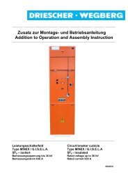
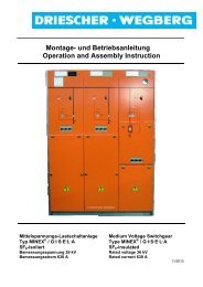
Montage- und Betriebsanleitung Operation- and Assembly Instruction
Montage- und Betriebsanleitung Operation- and Assembly Instruction
Montage- und Betriebsanleitung Operation- and Assembly Instruction

Erfolgreiche ePaper selbst erstellen
Machen Sie aus Ihren PDF Publikationen ein blätterbares Flipbook mit unserer einzigartigen Google optimierten e-Paper Software.
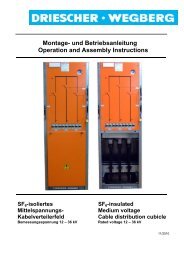
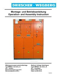
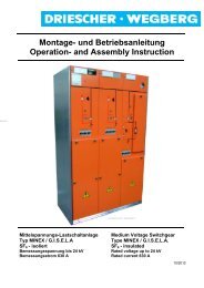
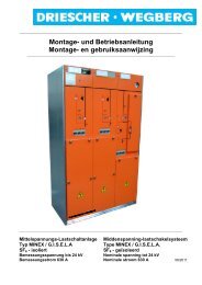
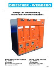
Mittelspannungs-Schaltanlage<br />
Folgende Schaltanlagen Fabrikat Driescher-<br />
Wegberg für Bemessungsspannungen 12kV/24kV<br />
sind maximal einbaubar:<br />
KSP1130:<br />
SF6–isolierte Lastschaltanlage vom Typ:<br />
MINEX-C 2/3/4 - Felder<br />
MINEX / G.I.S.E.L.A 2/3 - Felder<br />
KSP1430:<br />
SF6–isolierte Lastschaltanlage vom Typ:<br />
MINEX-C 2/3/4/5 - Felder<br />
MINEX / G.I.S.E.L.A 2/3/4 - Felder<br />
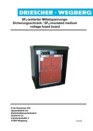
Folgende Sicherungsfelder sind in Stationen<br />
Fabrikat Driescher-Wegberg einbaubar:<br />
Luftisoliertes Sicherungsfeld:<br />
mit Sicherungen <strong>und</strong> Erdungsbrücke 12/24 kV<br />
SF6-isoliertes Laschenfeld:<br />
mit Sicherungen <strong>und</strong> Erder 12/24 kV<br />
Zur H<strong>and</strong>habung, Einsatz <strong>und</strong> Bedienung der<br />
eingebauten Anlagen <strong>und</strong> Geräte muss die produktspezifische<br />
<strong>Montage</strong>- <strong>und</strong> <strong>Betriebsanleitung</strong><br />
beachtet werden.<br />
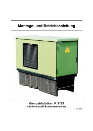
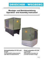
Transformatorraum<br />
Die Station kann mit folgenden Transformatoren<br />
ausgestattet werden:<br />
DIN-Transformatoren in Hermetikausführung mit<br />
Steckdurchführungen ≤ 630 kVA<br />
DIN-Transformatoren mit den maximalen Abmessungen:<br />
KSP1130: LxBxH=1600x900x2000 mm<br />
KSP1430: LxBxH=1600x1200x2000 mm<br />
werden in die F<strong>und</strong>amentwanne abgesenkt <strong>und</strong><br />
dort gegen Verschieben fixiert.<br />
Vorgefertigte <strong>und</strong> geprüfte Kabelbrücken verbinden<br />
den Transformator mit der MS-Schaltanlage.<br />
Der NS-seitige Anschluss erfolgt leistungsabhängig<br />
mit hochflexiblen, isolierten Leitungen.<br />
Erdungsanlage<br />
Die zentrale Erdungsschiene befindet sich unterhalb<br />
der NH-Sicherungslastschaltleiste im NS-<br />
Schaltraum. An ihr wird das bauseits verlegte<br />
Erdungsb<strong>and</strong> oder der Tiefenerder angeschlossen.<br />
Dadurch sind alle leitfähigen Gehäuseteile<br />
mit der Haupterde verb<strong>und</strong>en.<br />
10 KSP1130 / KSP1430<br />
DRIESCHER • WEGBERG<br />
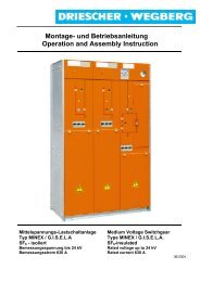
Medium Voltage Switchgear<br />
The following medium voltage switchgear<br />
make Driescher-Wegberg 12/24 kV can be<br />
installed:<br />
KSP1130:<br />
SF6-insulated switchgear of type:<br />
MINEX-C 2/3/4-cubicles<br />
MINEX / G.I.S.E.L.A 2/3-cubicles<br />
KSP1430:<br />
SF6-insulated switchgear of type:<br />
MINEX-C 2/3/4/5-cubicles<br />
MINEX / G.I.S.E.L.A 2/3/4-cubicles<br />
Following bus riser cubicles can be installed in<br />
transformer stations make Driescher:<br />
Air-insulated bus riser cubicles:<br />
with fuses 12/24 kV<br />
SF6-insulated bus riser cubicles:<br />
with fuses <strong>and</strong> earthing switch 12/24 kV<br />
For h<strong>and</strong>ling, use <strong>and</strong> operation of the installed<br />
switchgear <strong>and</strong> devices the relevant Operating<br />
<strong>and</strong> <strong>Assembly</strong> <strong>Instruction</strong> has to be observed.<br />
Transformer compartment<br />
The station can be equipped with the following<br />
transformers:<br />
DIN-transformes in hermetically sealed design<br />
with plug-in bushings ≤ 630 kVA<br />
DIN-transformers with the maximum dimensions<br />
(LxWxH=1600x900x2000 mm) are lowered into<br />
the fo<strong>und</strong>ation trough <strong>and</strong> are fixed against displacing<br />
there.<br />
Pre-assembled <strong>and</strong> tested cable joints connect<br />
the transformer with the MV-switchgear. The connection<br />
on LV side is made power-related with<br />
highly flexible insulated wires.<br />
Earthing system<br />
The central earthing rail is provided below the LV<br />
fuse rail strip in the LV switch compartment. Here<br />
the gro<strong>und</strong> strap installed on site or the gro<strong>und</strong><br />
rod is connected. Thus, all conductive housing<br />
parts are connected with the main earth.