Montage- und Betriebsanleitung Operation and Assembly Instructions
Montage- und Betriebsanleitung Operation and Assembly Instructions
Montage- und Betriebsanleitung Operation and Assembly Instructions

Sie wollen auch ein ePaper? Erhöhen Sie die Reichweite Ihrer Titel.
YUMPU macht aus Druck-PDFs automatisch weboptimierte ePaper, die Google liebt.
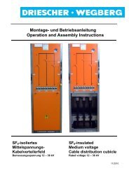
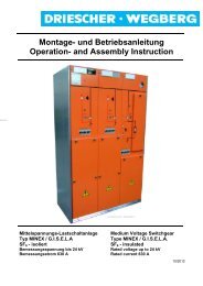
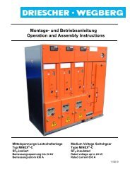
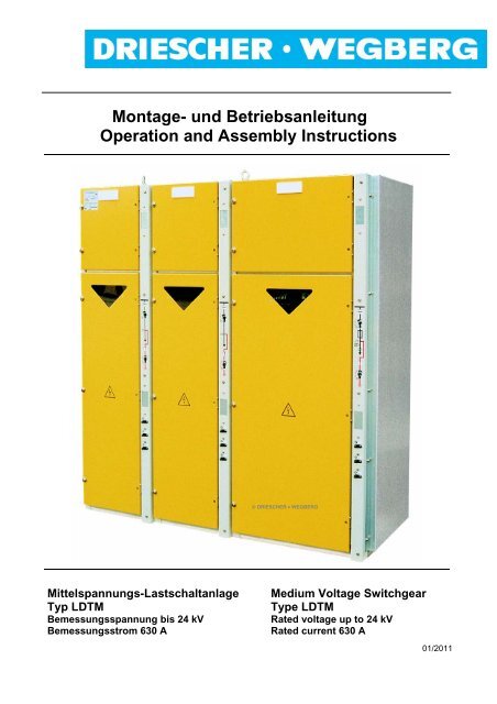
<strong>Montage</strong>- <strong>und</strong> <strong>Betriebsanleitung</strong><br />
<strong>Operation</strong> <strong>and</strong> <strong>Assembly</strong> <strong>Instructions</strong><br />
Mittelspannungs-Lastschaltanlage<br />
Typ LDTM<br />
Bemessungsspannung bis 24 kV<br />
Bemessungsstrom 630 A<br />
© DRIESCHER • WEGBERG<br />
Medium Voltage Switchgear<br />
Type LDTM<br />
Rated voltage up to 24 kV<br />
Rated current 630 A<br />
01/2011
DRIESCHER • WEGBERG<br />
Alle Rechte vorbehalten / All rights reserved<br />
© DRIESCHER • WEGBERG 2011<br />
2 LDTM
INHALT<br />
INHALT.......................................................................... 3<br />
SICHERHEITSVORSCHRIFTEN................................... 4<br />
ALLGEMEINE INFORMATION ..................................... 5<br />
BESTIMMUNGSGEMÄßE VERWENDUNG ...................... 5<br />
QUALIFIZIERTES PERSONAL...................................... 5<br />
NORMEN UND VORSCHRIFTEN .................................. 6<br />
BETRIEBSBEDINGUNGEN .......................................... 7<br />
HAFTUNGSBESCHRÄNKUNGEN .................................. 7<br />
BESCHREIBUNG .......................................................... 8<br />
ZU DIESER ANLEITUNG ............................................. 8<br />
ALLGEMEINES .......................................................... 9<br />
ANTI-BERST-SYSTEM (ABS) .................................. 10<br />
KAPAZITIVE SCHNITTSTELLE (OPTION) .................... 11<br />
ÜBERSICHT............................................................ 13<br />
TECHNISCHE DATEN ................................................ 14<br />
BEMESSUNGSGRÖßEN............................................ 14<br />
HH-SICHERUNGSEINSÄTZE..................................... 15<br />
ABMESSUNGEN UND GEWICHTE.............................. 16<br />
MONTAGE................................................................... 18<br />
SICHERHEITSHINWEISE FÜR TRANSPORT, MONTAGE,<br />
BETRIEB UND WARTUNG......................................... 18<br />
ABLADEN UND TRANSPORTIEREN............................ 18<br />
AUFSTELLEN DER SCHALTANLAGE .......................... 20<br />
SCHALTANLAGE ERDEN .......................................... 22<br />
KUPPELN DER AUSLÖSEWELLEN DES ANTI-BERST-<br />
SYSTEMS BEI EINZELFELDLIEFERUNG...................... 24<br />
ANSCHLUSS........................................................... 25<br />
BETRIEB ..................................................................... 27<br />
INBETRIEBNAHME ................................................... 27<br />
BEDIENUNG ........................................................... 28<br />
SCHALTEN DES LASTTRENNSCHALTERS .................. 28<br />
SCHALTEN DES ERDUNGSSCHALTERS ..................... 30<br />
AUSTAUSCH DER HH-SICHERUNGSEINSÄTZE .......... 31<br />
KABELPRÜFUNG..................................................... 32<br />
MAßNAHMEN NACH AUSLÖSUNG DES ANTI-BERST-<br />
SENSORS .............................................................. 33<br />
EINSCHUBPLATTE (ZUBEHÖR)................................. 33<br />
OPTIONALE AUSSTATTUNG .................................... 34<br />
MOTORANTRIEB (OPTION) ...................................... 34<br />
MAGNETAUSLÖSER (OPTION) ................................. 37<br />
KURZSCHLUSSANZEIGER / ERDSCHLUSSANZEIGER<br />
(OPTION)............................................................... 38<br />
INSTANDHALTUNG.................................................... 38<br />
WARTUNG ............................................................. 38<br />
AUSTAUSCH VON BAUTEILEN .................................. 40<br />
ENTSORGUNG........................................................ 40<br />
FEHLERBEHEBUNG .................................................. 42<br />
ANHANG A.................................................................. 43<br />
LDTM SCHALTANLAGEN OHNE ANTI-BERST-<br />
SYSTEM................................................................. 43<br />
CONTENTS<br />
DRIESCHER • WEGBERG<br />
CONTENTS...................................................................... 3<br />
SAFETY REGULATIONS................................................. 4<br />
GENERAL INFORMATION.............................................. 5<br />
INTENDED USE............................................................ 5<br />
QUALIFIED PERSONNEL ............................................... 5<br />
STANDARDS AND SPECIFICATIONS ............................... 6<br />
SERVICE CONDITIONS................................................... 7<br />
RESTRICTIONS ON LIABILITY....................................... 7<br />
DESCRIPTION ................................................................. 8<br />
ABOUT THIS MANUAL................................................... 8<br />
GENERAL ................................................................... 9<br />
ANTI-BURST-SYSTEM (ABS)..................................... 10<br />
CAPACITIVE INTERFACE (OPTION).............................. 11<br />
OVERVIEW ............................................................... 13<br />
TECHNICAL DATA ........................................................ 14<br />
RATED VALUES ......................................................... 14<br />
HV HRC FUSES ....................................................... 15<br />
DIMENSIONS AND WEIGHTS ....................................... 16<br />
ASSEMBLY.................................................................... 18<br />
SAFETY INSTRUCTIONS FOR TRANSPORT, ASSEMBLY,<br />
OPERATION AND MAINTENANCE.................................. 18<br />
DISCHARGE AND TRANSPORT..................................... 18<br />
POSITIONING THE SWITCHGEAR ................................. 20<br />
EARTHING OF THE SWITCHGEAR ................................ 22<br />
COUPLING OF TRIPPING SHAFTS OF ANTI- BURST-<br />
SYSTEM FOR SINGLE CUBICLE SUPPLIES .................... 24<br />
CONNECTION............................................................ 25<br />
OPERATION .................................................................. 27<br />
SETTING TO WORK.................................................... 27<br />
OPERATION .............................................................. 28<br />
SWITCHING THE SWITCH-DISCONNECTOR................... 28<br />
SWITCHING THE EARTHING SWITCH............................ 30<br />
REPLACEMENT OF THE HV HRC FUSES ....................... 31<br />
CABLE TESTING ........................................................ 32<br />
STEPS AFTER AN ACTIVATION OF ANTI- BURST-<br />
SENSOR....................................................................................33<br />
INSULATING PROTECTIVE PLATE (ACCESSORIES) ............33<br />
OPTIONAL EQUIPMENT............................................... 34<br />
MOTOR MECHANISM (OPTION) ................................... 34<br />
TRIP COIL (OPTION)................................................... 37<br />
SHORT CIRCUIT INDICATOR /EARTH FAULT INDICATOR<br />
(OPTION) .................................................................. 38<br />
SERVICING .................................................................... 38<br />
MAINTENANCE.......................................................... 38<br />
EXCHANGE OF COMPONENTS .................................... 40<br />
WASTE DISPOSAL ..................................................... 40<br />
TROUBLE-SHOOTING .................................................. 42<br />
APPENDIX A.................................................................. 43<br />
LDTM-SWITCHGEARS WITHOUT ANTI-BURST-<br />
SYSTEM ................................................................... 43<br />
LDTM 3
DRIESCHER • WEGBERG<br />
Sicherheitsvorschriften<br />
Die in der <strong>Montage</strong>- <strong>und</strong> <strong>Betriebsanleitung</strong> enthaltenen<br />
Hinweise zu<br />
- Transport<br />
- <strong>Montage</strong><br />
- Inbetriebnahme<br />
- Bedienung<br />
- Wartung<br />
der Mittelspannungs-Schaltanlage müssen unbedingt<br />
beachtet werden.<br />
Wichtige sicherheitstechnische Hinweise sind durch<br />
folgende Symbole gekennzeichnet. Befolgen Sie<br />
diese Hinweise, um Unfälle <strong>und</strong> Beschädigungen der<br />
Mittelspannungs-Schaltanlage zu vermeiden.<br />
Warnung vor einer Gefahrenstelle!<br />
Warnung vor elektrischer Spannung!<br />
Besondere Hinweise!<br />
Diese Symbole finden Sie bei allen Hinweisen in<br />
dieser <strong>Betriebsanleitung</strong>, bei denen Verletzungs-<br />
oder Lebensgefahr besteht.<br />
Beachten Sie diese Hinweise <strong>und</strong> geben Sie diese<br />
an <strong>and</strong>eres qualifiziertes Personal weiter. Neben<br />
diesen Hinweisen sind<br />
- Sicherheitsvorschriften,<br />
- Unfallverhütungsvorschriften,<br />
- Richtlinien <strong>und</strong> anerkannte Regeln der Technik<br />
sowie sämtliche Instruktionen dieser <strong>Montage</strong>- <strong>und</strong><br />
<strong>Betriebsanleitung</strong> zu beachten!<br />
4 LDTM<br />
Safety Regulations<br />
It is imperative that the notes in these Operating <strong>Instructions</strong><br />
regarding<br />
- transport<br />
- assembly<br />
- putting into service<br />
- operation<br />
- maintenance<br />
of the medium voltage switchgear must be adhered<br />
to.<br />
Important instructions such as safety notes are identified<br />
by means of the following symbols. Follow these<br />
notes to avoid accidents <strong>and</strong> damages involving the<br />
medium voltage switchgear.<br />
Warning of a danger area!<br />
Warning of electrical voltage!<br />
Special Hints!<br />
You will find these symbols with all hints given in this<br />
manual, where risk of injury or danger of live exists.<br />
Comply with these notes <strong>and</strong> pass them on to other<br />
qualified electrical technicians. Aside from these<br />
notes, comply with<br />
- safety specifications<br />
- accident prevention regulations<br />
- guidelines <strong>and</strong> recognized rules of technology<br />
as well as all instructions <strong>and</strong> notes in these <strong>Operation</strong><br />
<strong>and</strong> <strong>Assembly</strong> <strong>Instructions</strong>!
Allgemeine Information<br />
Bestimmungsgemäße Verwendung<br />
Die DRIESCHER-LDTM-Schaltanlage ist eine typgeprüfte<br />
Mittelspannungs-Schaltanlage für Innenraumanwendung<br />
mit Mehrzwecklasttrennschaltern.<br />
Die Löschkammern des Schaltgerätes arbeiten als<br />
geschlossenes System nach dem Hartgas-Prinzip.<br />
Die Mittelspannungs-Schaltanlage vom Typ LDTM<br />
ist ausschließlich zum Schalten <strong>und</strong> Verteilen elektrischer<br />
Energie mit Strömen bis 630 A bei Spannungen<br />
bis 24 kV, 50/60 Hz bestimmt.<br />
Der einw<strong>and</strong>freie <strong>und</strong> sichere Betrieb der Schaltanlage<br />
setzt voraus:<br />
• Sachgemäßer Transport <strong>und</strong> fachgerechte Lagerung<br />
• Fachgerechte <strong>Montage</strong> <strong>und</strong> Inbetriebnahme<br />
• Sorgfältige Bedienung <strong>und</strong> Inst<strong>and</strong>haltung durch<br />
qualifiziertes Personal<br />
• Die Beachtung dieser Anleitung<br />
• Die Einhaltung der am Aufstellungsort geltenden<br />
Aufstellungs-, Betriebs- <strong>und</strong> Sicherheitsbestimmungen<br />
Eine <strong>and</strong>ere oder darüber hinausgehende Verwendung<br />
gilt als nicht bestimmungsgemäß. Für hieraus<br />
resultierende Schäden haftet der Hersteller nicht.<br />
Das Risiko trägt allein der Betreiber/Benutzer.<br />
Qualifiziertes Personal<br />
Qualifiziertes Personal im Sinne dieser Anleitung<br />
sind Personen, die mit der Aufstellung, <strong>Montage</strong>,<br />
Inbetriebsetzung, Inst<strong>and</strong>haltung <strong>und</strong> dem Betrieb<br />
des Produktes vertraut sind <strong>und</strong> durch ihre Tätigkeit<br />
über entsprechende Qualifikationen verfügen, wie<br />
z.B.:<br />
• Ausbildung <strong>und</strong> Unterweisung bzw. Berechtigung,<br />
Stromkreise <strong>und</strong> Geräte/Systeme gemäß<br />
den St<strong>and</strong>ards der Sicherheitstechnik ein- <strong>und</strong><br />
auszuschalten, zu erden <strong>und</strong> zu kennzeichnen.<br />
• Ausbildung oder Unterweisung gemäß den<br />
St<strong>and</strong>ards der Sicherheitstechnik in Pflege <strong>und</strong><br />
Gebrauch angemessener Sicherheitsausrüstung.<br />
• Schulung <strong>und</strong> Erste Hilfe zum Verhalten bei<br />
möglichen Unfällen.<br />
DRIESCHER • WEGBERG<br />
General Information<br />
Intended use<br />
The DRIESCHER-LDTM switchgear is a typetested<br />
medium voltage switchgear for indoor applications<br />
with general purpose switches. The<br />
arcing chambers of the switch are working as a<br />
closed system according. to the hard-gasprinciple.<br />
The medium voltage switchgear type LDTM was<br />
exclusively designed for the operation <strong>and</strong> distribution<br />
of electric energy with currents up to 630 A<br />
<strong>and</strong> voltages up to 24kV, 50/60 Hz.<br />
The proper <strong>and</strong> safe operation of the switchgear<br />
requires the following pre-conditions:<br />
• Appropriate transport <strong>and</strong> correct storing<br />
• Professional assembly <strong>and</strong> setting to work<br />
• Accurate operation <strong>and</strong> maintenance through<br />
qualified personnel<br />
• The observation of this manual<br />
• The compliance with the regulations for installation,<br />
operation <strong>and</strong> safety, valid at site.<br />
Another or an extended use is not regarded as intended.<br />
The manufacturer does not guarantee for<br />
damages resulting from it.<br />
The risk is exclusively in the h<strong>and</strong>s of the operator/user.<br />
Qualified personnel<br />
Qualified personnel in accordance with this manual<br />
are professionals, being familiar with the installation,<br />
assembly, setting to work, maintenance <strong>and</strong><br />
operation of this product <strong>and</strong> have the relevant<br />
qualifications, i.e.<br />
• Education <strong>and</strong> instruction as well as authorised<br />
permission to switch ON <strong>and</strong> OFF, to<br />
earth <strong>and</strong> to mark circuits <strong>and</strong> devices/<br />
systems according to the st<strong>and</strong>ards of safety<br />
engineering.<br />
• Education or training according to the st<strong>and</strong>ards<br />
of safety engineering in care <strong>and</strong> use of<br />
adequate safety equipment.<br />
• Training <strong>and</strong> First Aid for the behaviour with<br />
possible accidents.<br />
LDTM 5
DRIESCHER • WEGBERG<br />
Normen <strong>und</strong> Vorschriften<br />
Vorschrift der Berufsgenossenschaft<br />
BGV A1 Allgemeine Vorschriften<br />
BGV A3 Elektrische Anlagen <strong>und</strong> Betriebsmittel<br />
DIN/VDE-Bestimmungen<br />
DIN VDE 0101 Errichten von Starkstromanlagen<br />
mit Nennspannungen<br />
über 1 kV.<br />
DIN VDE 0105 Betrieb von elektrischen<br />
Anlagen.<br />
VDE 0670 Teil 4 Hochspannungssicherungen.<br />
VDE 0670 Teil 301 Hochspannungs-Lastschalter.<br />
VDE 0671 Gemeinsame Bestimmungen<br />
Teil 1 für Hochspannungs-<br />
Schaltgeräte-Normen.<br />
VDE 0671 Teil 102 Wechselstromtrennschalter<br />
Erdungsschalter.<br />
VDE 0671 Teil 105 Hochspannungs-Lastschalter-<br />
Sicherungs-Kombination.<br />
VDE 0671 Teil 200 Metallgekapselte Wechselstrom-Schaltanlagen<br />
für Bemessungsspannungen<br />
über<br />
1kV bis einschließlich 52 kV.<br />
VDE 0682 Teil 415 Spannungsprüfsysteme<br />
6 LDTM<br />
St<strong>and</strong>ards <strong>and</strong> Specifications<br />
Specifications of the German Trade<br />
Association<br />
BGV-A1 General specifications<br />
BGV-A3 Electrical systems <strong>and</strong><br />
equipment<br />
St<strong>and</strong>ards<br />
DIN VDE 0101 Power installations exceeding<br />
AC 1kV.<br />
EN 50110-1 <strong>Operation</strong> of electrical<br />
installations.<br />
IEC 60282-1 High voltage fuses.<br />
IEC 60265-1 High-voltage switches<br />
IEC 62271-1 Common specifications for<br />
high-voltage switchgear <strong>and</strong><br />
controlgear st<strong>and</strong>ards.<br />
IEC 62271-102 Alternating current<br />
disconnectors <strong>and</strong> earthing<br />
switches.<br />
IEC 62271-105 High-voltage alternating current<br />
switch-fuse combinations<br />
IEC 62271-200 Alternating current metalenclosed<br />
switchgear <strong>and</strong><br />
controlgear for rated voltages<br />
above 1 kV up to <strong>and</strong> including<br />
52 kV<br />
IEC 61243-5 Voltage detecting systems
Betriebsbedingungen<br />
Normale Betriebsbedingungen<br />
Die Schaltanlage ist für normale Betriebsbedingungen<br />
von Innenraum-Schaltgeräten <strong>und</strong> –<br />
Schaltanlagen bei folgenden Umgebungstemperaturen<br />
ausgelegt:<br />
Höchstwert +60 °C*<br />
Tiefstwert -25 °C<br />
Sonder-Betriebsbedingungen<br />
Nach VDE 0671 Teil 1 können von den normalen<br />
Betriebsbedingungen abweichende Betriebsbedingungen<br />
zwischen Hersteller <strong>und</strong> Betreiber vereinbart<br />
werden. Zu jeder Sonder-Betriebsbedingung muss<br />
der Hersteller vorher befragt werden.<br />
* bei Umgebungstemperaturen > 40°C Reduktionsfaktoren<br />
berücksichtigen<br />
Haftungsbeschränkungen<br />
Alle in dieser <strong>Montage</strong>- <strong>und</strong> <strong>Betriebsanleitung</strong> enthaltenen<br />
technischen Informationen, Daten <strong>und</strong> Hinweise<br />
für die Installation, Bedienung <strong>und</strong> Wartung der<br />
Schaltanlage entsprechen dem St<strong>and</strong> der Drucklegung<br />
<strong>und</strong> erfolgen unter Berücksichtigung unserer<br />
bisherigen Erfahrungen <strong>und</strong> Erkenntnisse nach bestem<br />
Wissen.<br />
Für etwaige Fehler oder Unterlassungen haften wir<br />
unter Ausschluss weiterer Ansprüche im Rahmen<br />
der im Hauptvertrag eingegangenen Mängelhaftungsverpflichtungen.<br />
Ansprüche auf Schadensersatz,<br />
gleich aus welchem Rechtsgr<strong>und</strong> derartige<br />
Ansprüche hergeleitet werden, sind ausgeschlossen,<br />
soweit sie nicht auf Vorsatz oder grober Fahrlässigkeit<br />
beruhen.<br />
DRIESCHER • WEGBERG<br />
Operating Conditions<br />
St<strong>and</strong>ard operating conditions<br />
The switchgear is designed for normal service<br />
conditions of indoor switches <strong>and</strong> indoor switchgears<br />
at the following ambient temperatures:<br />
Maximum value + 60°C*<br />
Lowest value -25° C<br />
Special operating conditions<br />
In accordance with IEC 62271-1, the manufacturer<br />
<strong>and</strong> the user can agree to operating conditions<br />
that deviate from the st<strong>and</strong>ard conditions. The<br />
manufacturer must be asked in advance about<br />
any special service condition.<br />
* at ambient temperatures > 40°C take care of the reduction<br />
factors<br />
Restrictions on Liability<br />
All technical information, data <strong>and</strong> notes for the<br />
installation, operation <strong>and</strong> maintenance of the<br />
medium voltage switchgear contained in these<br />
<strong>Operation</strong> <strong>and</strong> <strong>Assembly</strong> <strong>Instructions</strong> are current as<br />
of the day of printing <strong>and</strong> are stated to the best of our<br />
knowledge on the basis of our experience <strong>and</strong> knowhow.<br />
We accept liability for any errors or omissions, to<br />
the exclusion of further claims, within the scope<br />
of the agreed warranty. Claims for compensation<br />
for damage are excluded, regardless of the<br />
legal basis for those claims, unless they are<br />
the result of intent or gross negligence.<br />
Translations are made to the best of knowledge.<br />
Liability of any kind shall therefore not be accepted<br />
for faults made in the translation even if the<br />
operating instructions are translated by us or by a<br />
third party. Solely the German text shall prevail.<br />
LDTM 7
DRIESCHER • WEGBERG<br />
Beschreibung<br />
Zu dieser Anleitung<br />
Diese Anleitung enthält aus Gründen der Übersichtlichkeit<br />
nicht sämtliche Detailinformationen zu allen<br />
Typen des Produktes. Sie kann auch nicht jeden<br />
denkbaren Fall der Aufstellung oder des Betriebes<br />
berücksichtigen. Einzelheiten zur technischen Auslegung,<br />
wie z.B. technische Daten, Sek<strong>und</strong>äreinrichtungen,<br />
Schaltpläne, entnehmen Sie bitte den Auftragsunterlagen.<br />
Die Schaltanlage unterliegt im Rahmen des technischen<br />
Fortschrittes einer ständigen Weiterentwicklung.<br />
Soweit auf den einzelnen Seiten dieser Anleitung<br />
nichts <strong>and</strong>eres vermerkt ist, bleiben Änderungen<br />
der angegebenen Werte <strong>und</strong> Abbildungen vorbehalten.<br />
Alle Maße sind in mm angegeben.<br />
Wenn Sie weitere Informationen wünschen oder falls<br />
Probleme auftreten, die in der Anleitung nicht ausführlich<br />
genug beh<strong>and</strong>elt werden, fordern Sie die<br />
Auskunft über unseren K<strong>und</strong>endienst oder die zuständige<br />
Vertretung an.<br />
Geben Sie bitte bei Rückfragen oder Ersatzteilbestellungen<br />
folgende auf dem Typenschild angegebene<br />
Daten an:<br />
- Stations-, Geräte-, Anlagentyp,<br />
- Fabrikationsnummer,<br />
- Baujahr.<br />
Durch Angabe dieser Daten ist gewährleistet, dass<br />
Ihnen die richtigen Informationen oder die benötigten<br />
Ersatzteile zugehen.<br />
Fritz Driescher KG<br />
Spezialfabrik für Elektrizitätswerksbedarf<br />
GmbH & Co.<br />
Postfach 1193; 41837 Wegberg<br />
Industriestraße 2; 41844 Wegberg<br />
Telefon 02434 81-1<br />
Telefax 02434 81446<br />
www.driescher-wegberg.de<br />
e-mail:info@driescher-wegberg.de<br />
Wir weisen darauf hin, dass der Inhalt dieser Anleitung<br />
nicht Teil einer früheren oder bestehenden Vereinbarung,<br />
oder Zusage eines Rechtsverhältnisses<br />
ist oder dieses ändern soll. Sämtliche Verpflichtungen<br />
der Firma DRIESCHER ergeben sich aus dem<br />
jeweiligen Kaufvertrag, der auch die vollständige <strong>und</strong><br />
allein gültige Mängelhaftungsregelung enthält. Diese<br />
vertraglichen Mängelhaftungsbestimmungen werden<br />
durch die Ausführungen dieser Anleitung weder erweitert<br />
noch beschränkt.<br />
8 LDTM<br />
Description<br />
About this manual<br />
Due to reasons of clarity this manual does not contain<br />
all detailed information about all types of this<br />
product. It also cannot consider every imaginable<br />
case of installation or operation. Details regarding the<br />
technical design, as i.e. technical data, secondary<br />
devices, diagrams please take from the order documents.<br />
The switchgear is within the scope of technical progress<br />
subject to a permanent development. As far as<br />
nothing else is noted on the single pages of this<br />
manual, the right of changes of the indicated values<br />
<strong>and</strong> drawings is reserved. All dimensions are indicated<br />
in mm.<br />
If you require more information or if problems arise,<br />
which are not enough discussed in detail, please ask<br />
our service department or the relevant representation<br />
for more information.<br />
Please indicate the following data shown on the<br />
nameplate for queries or spare parts:<br />
- station, switch or switchgear type,<br />
- serial number,<br />
- year of manufacture.<br />
Specifying these items ensures that you will receive<br />
the correct information or the required spare parts.<br />
Fritz Driescher KG<br />
Spezialfabrik für Elektrizitätswerksbedarf<br />
GmbH & Co.<br />
P.O. Box 1193, 41837 Wegberg<br />
Industriestraße 2, 41844 Wegberg<br />
Phone: 0049 2434 81-1<br />
Fax: 0049 2434 81-446<br />
www.driescher-wegberg.de<br />
e-mail:info@driescher-wegberg.de<br />
We point out that the content of this manual is not<br />
part of a previous or existing agreement, or is a<br />
promise of a legal relationship or shall change<br />
this. All obligations of DRIESCHER arise from the<br />
respective contract of sale, which includes the<br />
complete <strong>and</strong> exclusive valid warranty regulation.<br />
These contractual warranty regulations are neither<br />
extended nor limited through the remarks of this<br />
manual
Allgemeines<br />
Die DRIESCHER-luftisolierten Schaltanlagen sind<br />
gr<strong>und</strong>sätzlich für alle Arten von Innenraumaufstellungen<br />
in Stationsräumen geeignet z.B. für Keller-, Garagen-,<br />
Kunststoff-, Beton-, Turm- <strong>und</strong> Stahlblechstationen.<br />
Die in den Schaltanlagen vorh<strong>and</strong>enen Lasttrennschalter<br />
schalten Ströme bis 630A bei Spannungen<br />
bis 24kV, 50/60 Hz.<br />
Durch integrierte Anti-Berst-Systeme wird ein<br />
Höchstmaß an passiver <strong>und</strong> aktiver Sicherheit erreicht.<br />
Die Schaltanlage ist aus Einzel-Schaltfeldern aufgebaut.<br />
Die Schaltfelder können mit Mehrzweck-<br />
Lasttrennschaltern, kurzschlusseinschaltfesten Erdungsschaltern<br />
<strong>und</strong> HH-Sicherungen ausgerüstet<br />
werden.<br />
Aus einzelnen Feldern baukastenartig zusammengesetzt,<br />
kann die Anlage beliebig kombiniert <strong>und</strong><br />
später erweitert werden.<br />
Neben Kabel- <strong>und</strong> Trafofeldern sind auch Leistungsschalter-,<br />
Mess- <strong>und</strong> Übergabefelder lieferbar.<br />
Zur Beobachtung der Schaltgeräte sind Sichtfenster<br />
vorgesehen.<br />
Die Verschließung der Frontblenden erfolgt mit<br />
Schnellverschlüssen.<br />
Der Türanschlag kann je nach Bedarf links- bzw.<br />
rechtsseitig eingerichtet <strong>und</strong> nachträglich geändert<br />
werden.<br />
General<br />
DRIESCHER • WEGBERG<br />
The Driescher air-insulated switchgears are designed<br />
for all types of indoor applications in stations<br />
suitable for example in cellar-, garage-, polyester-,<br />
concrete-, tower- <strong>and</strong> sheet steel stations.<br />
The switch-disconnectors installed in the switchgear<br />
operate currents up to 630A at voltages up to<br />
24kV, 50/60 Hz.<br />
Due to the integrated Anti-Burst-System a maximum<br />
amount of passive <strong>and</strong> active safety is<br />
achieved.<br />
The switchgear is assembled from single cubicles.<br />
The cubicles can be equipped with general purpose<br />
switches, short-circuit-poof earthing switches<br />
<strong>and</strong> HV HRC-fuses.<br />
With its modular composition of single cubicles the<br />
switchgear can be arranged in any required combination<br />
<strong>and</strong> subsequently extended.<br />
In addition to cable- <strong>and</strong> transformer cubicles also<br />
circuit-breaker-, metering- <strong>and</strong> coupling cubicles<br />
can be delivered.<br />
For the observation of the switches inspection<br />
windows are provided.<br />
The locking of the front covers is performed by<br />
quick release locks.<br />
The door hinge can be on the left or on the<br />
right h<strong>and</strong> side according to the needs <strong>and</strong> can<br />
be changed later.<br />
LDTM 9
DRIESCHER • WEGBERG<br />
Anti-Berst-System (ABS)<br />
LDTM – Schaltanlagen sind st<strong>and</strong>ardmäßig mit Anti-<br />
Berst-System ausgerüstet.<br />
Hierzu ist ein Drucksensor im Dach oder in der<br />
Rückw<strong>and</strong> von jedem Schaltfeld angeordnet, der auf<br />
eine in der Rückw<strong>and</strong> angebrachten Auslösewelle<br />
wirkt.<br />
Diese Kombination ist ebenfalls in Schaltfeldern ohne<br />
aktiven Erdungsschalter (z.B. Transformatorfelder<br />
usw.) eingebaut.<br />
Die einzelnen Auslösewellen werden mitein<strong>and</strong>er<br />
verb<strong>und</strong>en <strong>und</strong> wirken auf die vorgespannten Erdungsschalterantriebe,<br />
die im Störlichtbogenfall die<br />
Erdungsschalter der Einspeisefelder zuschalten.<br />
Durch die Auslösung der Erdungsschalter wird der<br />
Störlichtbogenfehler in einen galvanischen Kurzschluss<br />
umgew<strong>and</strong>elt – der Störlichtbogen verlöscht.<br />
Die Funktion des Drucksensors ist nur dann<br />
gewährleistet, wenn der Abst<strong>and</strong> zwischen<br />
dem Dach, bzw. der Rückw<strong>and</strong> der<br />
Schaltanlage <strong>und</strong> der Stationsdecke, bzw.<br />
der W<strong>and</strong> mindestens 50 mm beträgt.<br />
Die manuelle EIN- <strong>und</strong> AUS-Schaltung kann bei<br />
vorgespanntem Antrieb wie üblich vorgenommen<br />
werden. Lasttrennschalter <strong>und</strong> Erdungsschalter sind<br />
st<strong>and</strong>ardmäßig gegenein<strong>and</strong>er verriegelt. Die Verriegelung<br />
lässt allerdings die EIN- Schaltung des<br />
Erdungsschalters zur Störlichtbogenbegrenzung<br />
unabhängig vom Schaltzust<strong>and</strong> der Gesamtanlage<br />
zu. Die zur Betätigung der in den Kabelfeldern vorgespannten<br />
Erdungsschalterantriebe benötigte Auslösewelle<br />
ist über Kupplungen aus einzelnen Wellenabschnitten<br />
aufgebaut. Dieser Modulaufbau der<br />
Schaltanlage erlaubt ohne größeren Aufw<strong>and</strong> eine<br />
Erweiterung der Schaltanlage.<br />
Hinweise zur Kupplung der Auslösewellen siehe<br />
Seite 24.<br />
10 LDTM<br />
Anti-Burst-System (ABS)<br />
As a st<strong>and</strong>ard, the LDTM switchgears are equipped<br />
with an Anti-Burst-System.<br />
For that a pressure sensor is installed in the roof or<br />
in the rear wall of each cubicle, which works onto a<br />
tripping shaft situated in the back wall.<br />
This combination is also installed in cubicles without<br />
an active earthing switch (i.e. transformer cubicles<br />
etc.).<br />
The single tripping shafts are being connected <strong>and</strong><br />
work onto the preloaded drives of the earthing<br />
switches. In case of an arc fault, the earthing switches<br />
in the incoming cubicles are actuated.<br />
By the activation of the earthing switch the arc fault<br />
is transformed into a galvanic short circuit <strong>and</strong> the<br />
arcing fault is extinguished.<br />
The function of the pressure sensor is only<br />
guaranteed, provided there is a space of<br />
minimum 50 mm between the switchgear<br />
roof respectively the rear wall <strong>and</strong> the ceiling<br />
respectively the wall of the substation.<br />
The manual ON-<strong>and</strong> OFF-operation can be performed<br />
as usual with a preloaded drive. As a st<strong>and</strong>ard,<br />
switch-disconnector <strong>and</strong> earthing switches are<br />
interlocked against each other.<br />
The locking, however, permits the activation of the<br />
earthing switch for the arc-limitation independent<br />
from the switching state of the whole switchgear. The<br />
tripping shaft for actuating the preloaded drives of the<br />
earthing switches in the cable cubicles is made of<br />
single shaft sections, which are coupled. This modular<br />
construction of the switchgear permits a simple<br />
extension of the switchgear.<br />
For hints regarding coupling of tripping shafts see<br />
page 24.
Kapazitive Schnittstelle (Option)<br />
Spannungsfreiheit feststellen über die kapazitive<br />
Schnittstelle nach VDE 0682 Teil 415<br />
Die Prüfung auf Spannungsfreiheit nach HR-System<br />
(70...90 V am Messpunkt bei 2,5 μA) erfolgt mit kapazitiven<br />
Spannungsanzeigegeräten an den Messbuchsen<br />
L1, L2, L3.<br />
Benutzen Sie nur Prüfgeräte nach VDE 0682<br />
Teil 415 für HR-Systeme. Beachten Sie die<br />
<strong>Betriebsanleitung</strong> der Prüfgerätehersteller<br />
<strong>und</strong> VDE 0682 Teil 415. Prüfen Sie die Prüfgeräte<br />
vor Gebrauch auf Funktion!<br />
- Schutzstöpsel entfernen<br />
- Spannungsanzeigegerät nach <strong>Betriebsanleitung</strong><br />
des Herstellers mit Messbuchsen verbinden <strong>und</strong><br />
auf Spannungsfreiheit prüfen.<br />
- Nach der Prüfung Spannungsanzeigegerät von<br />
den Messbuchsen trennen.<br />
- Schutzstöpsel auf Messbuchsen stecken, um<br />
das Verschmutzen der Messbuchsen zu verhindern.<br />
Keine Kurzschlussstecker verwenden! Die<br />
Schutzfunktion der spannungsbegrenzenden<br />
Sollbruchstelle wird bei Verwendung von<br />
Kurzschlusssteckern unwirksam!<br />
Funktionsprüfung: siehe Skizze auf nachfolgender<br />
Seite.<br />
Wiederholungsprüfung: In festen Zeitabständen<br />
durch o.g. Funktionsprüfung bei bekannter Betriebsspannung.<br />
(Letzte Wiederholungs- / Funktionsprüfung<br />
siehe Aufdruck am Koppelteil).<br />
Integriertes Spannungsanzeigegerät<br />
Optional sind integrierte Spannungsanzeigegeräte<br />
zur Feststellung der Spannungsfreiheit nach VDE<br />
0682 Teil 415 erhältlich.<br />
Mit integrierten Spannungsanzeigesystemen entfällt<br />
die Wiederholungsprüfung. Bitte beachten Sie hierzu<br />
die entsprechende Bedienungsanleitung.<br />
DRIESCHER • WEGBERG<br />
Capacitive Interface (Option)<br />
Verify the isolation from supply via the capacitive<br />
interface according to IEC 61243-5.<br />
The check for isolation from supply according to the<br />
HR-system (70…90 V at the measuring point with<br />
2,5 μA) is performed with capacitive voltage indicators<br />
on the measuring sockets L1, L2, L3.<br />
only use test instruments corresponding to<br />
IEC 61243-5 for HR Systems. Observe the<br />
operating manual issued by the manufacturer<br />
of the test instruments <strong>and</strong> IEC<br />
61243-5. Check the test instruments for<br />
proper operation before usage!<br />
- Remove the protective caps.<br />
- Connect the voltage indicating device with the<br />
measuring sockets according to the operating<br />
instructions of the manufacturer <strong>and</strong> check, if<br />
the switchgear is dead.<br />
- After the check, separate the voltage indicating<br />
device from the measuring sockets.<br />
- Put the protective caps onto the measuring<br />
sockets to avoid dirt deposit.<br />
Do not use any shorting plugs! The protective<br />
function of the declared breaking point<br />
that limits voltage becomes invalid with the<br />
use of shorting plugs.<br />
Functional Test: see sketch on next page.<br />
Repeat Test: In fixed intervals with the abovementioned<br />
functional test <strong>and</strong> a predetermined<br />
operating voltage. (Last repeat/functional test see<br />
marking on the coupling).<br />
Integrated voltage indication device<br />
As an option, integrated voltage indication devices<br />
are available to verify the isolation from supply<br />
according to IEC 61243-5.<br />
With integrated voltage indication systems the<br />
repeat test is omitted. Please observe the corresponding<br />
operating instructions.<br />
LDTM 11
DRIESCHER • WEGBERG<br />
Messaufbau zur Wiederholungs-/ Funktionsprüfung<br />
nach VDE 0682 Teil 415 Abschnitt 5.26.2<br />
U Messpunkt /<br />
Measuring point<br />
Koppelteil/<br />
Coupling part<br />
Phasengleichheit feststellen<br />
Führen Sie die kapazitive Phasenvergleichsmessung<br />
vor dem ersten Zuschalten<br />
eines unter Spannung stehenden Kabels<br />
durch.<br />
Für HR-Systeme gilt:<br />
- Entfernen Sie die Schutzstöpsel der Messbuchsen.<br />
- Verbinden Sie nachein<strong>and</strong>er die Messbuchsen<br />
(L1-L1, L2-L2, L3-L3) der betreffenden Kabelabgänge<br />
mit dem Phasenvergleichsgerät.<br />
- Stellen Sie die Phasengleichheit fest.<br />
- Stecken Sie die Schutzstöpsel auf die Messbuchsen.<br />
Für LR-Systeme gilt:<br />
- Beachten Sie die entsprechende Bedienungsanleitung<br />
des Phasenprüfgeräteherstellers.<br />
Benutzen Sie nur Prüfgeräte nach VDE 0682<br />
Teil 415 für HR-Systeme bzw. LR-Systeme.<br />
Beachten Sie die <strong>Betriebsanleitung</strong> der Prüfgerätehersteller<br />
<strong>und</strong> VDE 0682 Teil 415. Prüfen<br />
Sie die Prüfgeräte vor Gebrauch auf<br />
Funktion!<br />
12 LDTM<br />
C M<br />
Measuring arrangement for the Repeat / Functional<br />
Test according to IEC 61243-5, Section<br />
5.26.2<br />
Z<br />
Messstrom /<br />
measuring current I<br />
Messbeschaltung/<br />
measuring circuit<br />
Check the Phase Parity.<br />
M<br />
Z = 36 MΩ<br />
IM ≥ 2,5 μA*U/[√3*(0,45UN)]<br />
Bei U = UN folgt IM ≥ 3,2 μA<br />
at U = UN follows IM ≥ 3,2 μA<br />
R i<br />
µA<br />
Carry out the capacitive phase comparison<br />
test before the first connection of a<br />
live cable is performed.<br />
Valid for HR-systems:<br />
- Remove the protective caps from the measuring<br />
sockets.<br />
- Subsequently connect the measuring sockets<br />
(L-1-L1, L2-L2, L3-L3) of the corresponding<br />
cable ends with the phase comparison test<br />
device.<br />
- Check the phase parity.<br />
- Put the protective caps onto the measuring<br />
sockets.<br />
Valid for LR-systems:<br />
- The corresponding operating instructions issued<br />
by the manufacturer of the phase test device<br />
have to be observed.<br />
Only use test devices according to IEC<br />
61243-5 for HR Systems <strong>and</strong> LR Systems,<br />
resp. Observe the instructions issued by the<br />
manufacturer of the test equipments <strong>and</strong> IEC<br />
61243-5. Check the test instruments for proper<br />
operation before usage!
Übersicht Overview<br />
1<br />
10<br />
2<br />
3<br />
12<br />
8<br />
13<br />
1. Typenschild<br />
2. Sichtscheibe<br />
3. Blindschaltbild mit Schaltstellungsanzeigen<br />
4. Schaltstellungsanzeige für Lasttrennschalter<br />
5. Antriebsbuchse für Lasttrennschalter<br />
6. Schaltstellungsanzeige für Erdungsschalter<br />
7. Antriebsbuchse für Erdungsschalter<br />
8. Kabelschaltfeld<br />
9. Transformatorschaltfeld<br />
10. Einschubführung für Einschubplatte<br />
11. Beschriftungsschild<br />
12. Kurzschlussanzeiger (Option)<br />
13. Messbuchsen mit Schutzstöpsel für kapazitive<br />
Spannungsanzeige bzw. Phasenvergleich<br />
(Option)<br />
© DRIESCHER • WEGBERG<br />
DRIESCHER • WEGBERG<br />
1. name plate<br />
2. inspection window<br />
3. mimic diagram with switch position indication<br />
4. switch position indication for switch-<br />
disconnector<br />
5. drive socket for switch-disconnector<br />
6. switch position indication for earthing switch<br />
7. drive socket for earthing switch<br />
8. cable cubicle<br />
9. transformer cubicle<br />
10. insertion guide for insulating protective plate<br />
11. label<br />
12. short circuit indicator (option)<br />
13. measuring sockets with protective caps for<br />
capacitive voltage indication <strong>and</strong> phase comparison<br />
(option)<br />
LDTM 13<br />
11<br />
4<br />
5<br />
6<br />
7<br />
9
DRIESCHER • WEGBERG<br />
Technische Daten<br />
Bemessungsgrößen<br />
* bei Umgebungstemperaturen > 40°C Reduktionsfaktoren berücksichtigen<br />
** mit Überbrückungseinsatz. Mit HH-Sicherung ist der Bemessungsstrom<br />
abhängig vom eingesetzten Sicherungstyp<br />
14 LDTM<br />
Technical Data<br />
Rated values<br />
Bemessungsspannung 12 kV 17,5 kV 24 kV<br />
Bemessungs-StehwechselspannungBemessungs-Stehblitzstoßspannung<br />
28/32 kV 38/45 kV 50/60kV<br />
75/85 kV 95/110 kV 125/145 kV<br />
Rated voltage<br />
Rated power frequency<br />
withst<strong>and</strong> voltage<br />
Rated lightning impulse<br />
withst<strong>and</strong> voltage<br />
Bemessungsfrequenz 50/60 Hz Rated frequency<br />
Bemessungsstrom für Kabelschaltfelder<br />
Bemessungsstrom für Transformatorschaltfelder<br />
630 A<br />
400 A **<br />
Rated current for<br />
cable cubicles<br />
Rated current for transformer<br />
cubicles<br />
Bemessungs-Kurzzeitstrom 20 kA Rated short-time current<br />
Bemessungs-Stoßstrom 50 kA<br />
Bemessungs-Einschaltstrom 50 kA 50 kA 40 kA<br />
Bemessungs-Lastausschaltstrom 630 A<br />
Bemessungs-Ringausschaltstrom 630 A<br />
Bemessungs- Kabelausschaltstrom<br />
Bemessungs- Freileitungsausschaltstrom<br />
Bemessungs – Ausschaltstrom<br />
unter Erdschlussbedingungen<br />
Bemessungs – Transformatorausschaltstrom<br />
Klassifizierung des elektrischen<br />
Schaltvermögens<br />
Klassifizierung des mechanischen<br />
Schaltvermögens<br />
Bemessungs-Übergangsstrom<br />
gem. IEC 62271-105<br />
Öffnungszeit bei Schlagstiftbetätigung<br />
25 A<br />
25 A<br />
300 A<br />
10 A<br />
Klasse E3 / class E3<br />
Klasse M1 / class M1<br />
1250 A 1100 A 1000 A<br />
50 ms 70 ms 90 ms<br />
Rated short-circuit peak<br />
current<br />
Rated short-circuit making<br />
current<br />
Rated mainly active load<br />
breaking current<br />
Rated closed loop breaking<br />
current<br />
Rated cable charging<br />
breaking current<br />
Rated line charging<br />
breaking current<br />
Rated breaking current<br />
<strong>und</strong>er earth fault condition<br />
Rated no-load transformer<br />
breaking current<br />
Classification of the electrical<br />
switching capacity<br />
Classification of the mechanical<br />
switching capacity<br />
Rated transient current<br />
according to IEC 62271-105<br />
Tripping time after striker pin<br />
actuation<br />
Störlichtbogenqualifikation IAC AFL 20kA 1s Internal Arc Classification<br />
Zul. Umgebungstemperaturen - 25°C - + 60°C*<br />
Admissible ambient<br />
temperatures<br />
* at ambient temperatures > 40°C take care of the reduction<br />
factors<br />
** with solid link, in use with HRC-fuses the rated current<br />
depends on the installed fuse type
HH-Sicherungseinsätze<br />
Die Tabelle enthält Absicherungsempfehlungen für<br />
DRIESCHER HH-Sicherungseinsätze<br />
Transformator-<br />
Bemessungsleistung/<br />
Rated transformerpower<br />
[kVA]<br />
7,2 kV<br />
e=292 mm<br />
min/max.<br />
Bei Absicherung von Transformatoren mit einer Bemessungs-<br />
leistung von >1000kVA <strong>und</strong> ≤ 2000kVA sind <strong>and</strong>ere Sicherungsbaugrössen<br />
erforderlich.<br />
Bitte nehmen Sie Rücksprache mit der Fa. DRIESCHER.<br />
Aufgr<strong>und</strong> widersprüchlicher Aussagen der IEC 62271-105 <strong>und</strong><br />
IEC 60787 sind zur Absicherung von Transformatoren >630kVA<br />
keine eindeutigen Angaben nach IEC 62271-105 möglich.<br />
Bitte nehmen Sie Rücksprache mit der Fa. DRIESCHER.<br />
HV HRC fuses<br />
DRIESCHER • WEGBERG<br />
The table gives safety recommendations for the<br />
DRIESCHER HV HRC fuses<br />
Bemessungsstrom des Sicherungseinsatzes [A]<br />
Rated current of HV HRC fuses<br />
Bemessungsspannung<br />
12 kV<br />
e=292 mm<br />
min/max.<br />
17,5 kV<br />
e=442 mm<br />
min/max.<br />
24 kV<br />
e=442 mm<br />
min/max.<br />
50 10/16 6,3/10 6,3 6,3<br />
75 16/25 10/16 6,3/10 6,3<br />
100 16/25 16/25 10/16 6,3/10<br />
125 25/40 16/25 10/16 10<br />
160 25/40 16/40 16/25 10/16<br />
200 40/63 25/40 16/25 10/16<br />
250 40/63 31,5/40 25/40 16/25<br />
315 63/100 40/63 25/40 25/40<br />
400 63/100 40/63 31,5/40 25/40<br />
500 80/160 50/100 40/63 31,5/40<br />
630 100/200 63/100 40/63 31,5/63<br />
800 125/200 80 63/100 40/63<br />
1000 160/200 100 63/125 40/100<br />
e = Sicherungsstichmaß / size of the HRC fuse<br />
If transformers are secured with a rated power of ><br />
1000kVA<br />
<strong>and</strong> ≤ 2000kVA other fuse sizes are necessary. Please<br />
contact Messrs. Driescher.<br />
Due to controversial statements in IEC 62271-105 <strong>and</strong> IEC<br />
60787 no definite information according to IEC 62271-105<br />
for the protection of transformers can be given. Please<br />
contact Messrs. Driescher.<br />
LDTM 15
DRIESCHER • WEGBERG<br />
Abmessungen <strong>und</strong> Gewichte<br />
Schaltfeld 12 kV<br />
1900<br />
728<br />
A<br />
248 248<br />
14x25<br />
48 400 48<br />
Z<br />
Schnitt A-A<br />
© DRIESCHER • WEGBERG<br />
Optional sind weitere Felder unterschiedlicher Breite<br />
erhältlich. Bei Rückfragen setzen Sie sich bitte mit<br />
Firma Driescher in Verbindung.<br />
16 LDTM<br />
611 58<br />
58<br />
A<br />
Dimensions <strong>and</strong> Weights<br />
Cubicle 12 kV<br />
© DRIESCHER • WEGBERG © DRIESCHER • WEGBERG<br />
As an option, further cubicles with different widths<br />
are available. For more details please contact<br />
Messrs. Driescher.<br />
Abmessungen Kabelanschluss / Dimensions cable connection Gewichte / weights<br />
X Y Z<br />
Kabelschaltfeld / Cable cubicle 1142 366 500 ca. 145 kg<br />
Trafoschaltfeld / Transformer<br />
cubicle<br />
700 366 500 ca. 149 kg<br />
Y<br />
Abmessungen am Beispiel<br />
Transformatorfeld<br />
Dimensions based on example<br />
transformer cubicle<br />
X
Schaltfeld 24 kV<br />
1900<br />
1003<br />
A<br />
4<br />
373 373<br />
14x25<br />
48 650 48<br />
Schnitt A-A<br />
Optional sind weitere Felder unterschiedlicher Breite<br />
erhältlich. Bei Rückfragen setzen Sie sich bitte mit<br />
Firma Driescher in Verbindung.<br />
746<br />
886<br />
Cubicle 24 kV<br />
DRIESCHER • WEGBERG<br />
As an option, further cubicles with different widths<br />
are available. For more details please contact<br />
Messrs. Driescher.<br />
Abmessungen Kabelanschluss / Dimensions cable connection Gewichte / weights<br />
X Y Z<br />
Kabelschaltfeld / Cable cubicle 1142 366 500 ca. 195 kg<br />
Trafoschaltfeld / Transformer<br />
cubicle<br />
700 366 500 ca. 216 kg<br />
58<br />
58<br />
A<br />
© DRIESCHER • WEGBERG © DRIESCHER • WEGBERG<br />
© DRIESCHER • WEGBERG<br />
Y<br />
Abmessungen am Beispiel<br />
Kabelschaltfeld<br />
Dimensions based on example<br />
cable cubicle<br />
X<br />
LDTM 17
DRIESCHER • WEGBERG<br />
<strong>Montage</strong><br />
Erdungsschalter müssen aus Sicherheitsgründen<br />
während des Transports <strong>und</strong><br />
während der <strong>Montage</strong> in EIN - Stellung bleiben!<br />
Bringen Sie vor der Inbetriebnahme alle<br />
Erdungsschalter mit der Schaltkurbel in AUS –<br />
Stellung.<br />
Sicherheitshinweise für Transport, <strong>Montage</strong>,<br />
Betrieb <strong>und</strong> Wartung<br />
Beachten Sie die Sicherheitshinweise für das Heben<br />
<strong>und</strong> Transportieren der Schaltanlage!<br />
- Hebezeug, Lastaufnahmemittel <strong>und</strong> Anschlagmittel<br />
mit ausreichender Tragfähigkeit verwenden.<br />
- Anschlagmittel nur an den hierfür vorgesehenen<br />
Stellen anschlagen.<br />
- Seile, Ketten oder <strong>and</strong>ere Anschlagmittel müssen<br />
mit Sicherheitshaken ausgerüstet sein.<br />
- Keine angerissenen oder angescheuerten Seile<br />
verwenden.<br />
- Seile <strong>und</strong> Ketten nicht knoten <strong>und</strong> nicht an<br />
scharfen Kanten anlegen.<br />
- Lasten nicht über Personen hinweg heben.<br />
Abladen <strong>und</strong> Transportieren<br />
Beachten Sie die Sicherheitshinweise <strong>und</strong> Unfallverhütungsvorschriften!<br />
Verwenden Sie zum Heben <strong>und</strong> Transportieren<br />
der Schaltanlage Hebezeug, Lastaufnahmemittel<br />
<strong>und</strong> Anschlagmittel mit ausreichender<br />
Dimensionierung. Befestigen Sie<br />
Anschlagmittel nur an den vorgesehenen<br />
Kranungsvorrichtungen.<br />
- Abladen <strong>und</strong> Transportieren der Schaltanlage<br />
mit Kran oder Hubstapler.<br />
- Anschlagen der Anschlagmittel mit Sicherheitshaken<br />
nur an den seitlich angebrachten Kranungsvorrichtungen.<br />
- Benutzen Sie Anschlagmittel mit gleicher Länge.<br />
Der Winkel darf einen Wert von 90° nicht überschreiten.<br />
- Achten Sie auf gleichmäßige Gewichtsverteilung<br />
18 LDTM<br />
<strong>Assembly</strong><br />
For safety reasons the earthing switches<br />
have to remain in ON-position during transport<br />
<strong>and</strong> assembly! Before setting the<br />
switchgear to work all earthing switches<br />
have to be switched into OFF-position with<br />
the switch crank.<br />
Safety instructions for transport, assembly,<br />
operation <strong>and</strong> maintenance<br />
Respect the safety rules for the lifting <strong>and</strong> the<br />
transport of the switchgear!<br />
- Use a lifting device, transport <strong>and</strong> fixation<br />
means with a sufficient load carrying capacity.<br />
- Fix the fixation means only on the prescribed<br />
points.<br />
- Ropes, chains or other fixation means have<br />
to be equipped with safety hooks.<br />
- Do not use damaged or worn ropes.<br />
- Do not knit together ropes <strong>and</strong> chains <strong>and</strong><br />
do not fix them on sharp angles.<br />
- Do not lift loads over the heads of persons.<br />
Discharge <strong>and</strong> Transport<br />
Respect the safety hints <strong>and</strong> the anti-accident<br />
regulations!<br />
For the lifting <strong>and</strong> the transport of the<br />
switchgear use lifting devices, load carrying<br />
devices <strong>and</strong> fixing devices with sufficient<br />
force.<br />
Only fix the fixation means on the predetermined<br />
crane lifting devices.<br />
- Discharge <strong>and</strong> transport the switchgear with<br />
a crane or a lifting carriage.<br />
- Fixation of the fixation means with safety<br />
hooks only on the lifting devices arranged<br />
at both sides of the switchgear.<br />
- Use fixing means of the same length. The<br />
angle must not exceed a value of 90°.<br />
- Pay attention to an equal weight balance!
Nach dem Abladen<br />
- die Schaltanlage auf Beschädigungen prüfen,<br />
- das Zubehör laut Lieferschein auf Vollständigkeit<br />
kontrollieren.<br />
Dokumentieren <strong>und</strong> melden Sie Transportschäden<br />
sofort dem Spediteur <strong>und</strong> der Firma DRIESCHER.<br />
Anlage in der dargestellten<br />
Position transportieren.<br />
Front<br />
Beim Transport mit Gabelstapler oder<br />
Hubwagen Schwer-punkt der Anlage<br />
beachten!<br />
Die Schaltanlage ist kopflastig!<br />
© DRIESCHER • WEGBERG<br />
DRIESCHER • WEGBERG<br />
After discharge:<br />
- Check the switchgear for damages.<br />
- Control, if the accessories are complete according<br />
to the deli-very note.<br />
Document <strong>and</strong> report transport damages immediately<br />
to the carrier <strong>and</strong> to Messrs. DRIESCHER.<br />
© DRIESCHER • WEGBERG<br />
Transport switchgear in the<br />
shown position.<br />
Observe the centre of gravity of the<br />
switchgear during the transport with forklift<br />
or lift truck!<br />
The switchgear is top-heavy!<br />
LDTM 19
DRIESCHER • WEGBERG<br />
<strong>Montage</strong> der Schaltanlage<br />
Platzbedarf<br />
Den Platzbedarf der Schaltanlage entnehmen Sie<br />
dem Kapitel „Abmessungen <strong>und</strong> Gewichte“.<br />
Maß<br />
“L“<br />
Maß<br />
“T“<br />
12 kV:<br />
Anzahl Felder 500 mm breit+<br />
Anzahl Felder 750 mm breit+ 76 mm<br />
24 kV:<br />
Anzahl Felder 750 mm breit+<br />
Anzahl Felder 900 mm breit+ 84 mm<br />
12 kV: 728 mm<br />
24 kV: 1003 mm<br />
- Achten Sie bei Innenraum-Stationen auf ausreichende<br />
Breite der Gänge <strong>und</strong> Zugangsräume,<br />
um freie Bewegung <strong>und</strong> Transport zu ermöglichen.<br />
- Mindestbreite des Bedienganges: 800mm.<br />
- Die Mindestbreite des Bedienganges darf nicht<br />
unterschritten bzw. durch in den Gang hineinragende<br />
Teile eingeengt werden.<br />
Stellen Sie die Schaltanlage so auf, dass<br />
- Ausgänge <strong>und</strong> Türen von Innenraumstationen<br />
frei zugänglich sind.<br />
- Fluchtwege innerhalb der Station nicht mehr als<br />
20 m betragen.<br />
- Stellen Sie die Schaltanlage nicht in explosionsgefährdete<br />
oder staubexplosionsgefährdete<br />
Räume auf.<br />
20 LDTM<br />
L<br />
Measure<br />
”L”<br />
Switchgear Installation<br />
Necessary space<br />
The space needed for the switchgear positioning is<br />
shown in chapter “dimensions <strong>and</strong> weights”.<br />
© DRIESCHER • WEGBERG<br />
Measure<br />
“T“<br />
T<br />
12 kV:<br />
number of cubicles 500 mm width +<br />
number of cubicles 750 mm width + 76 mm<br />
24 kV:<br />
number of cubicles 750 mm width +<br />
number of cubicles 900 mm width + 84 mm<br />
12 kV: 728 mm<br />
24 kV: 1003 mm<br />
- In case of indoor stations make sure that there is<br />
sufficient width between the corridors <strong>and</strong> the<br />
access areas for movement <strong>and</strong> transport reasons.<br />
- Minimum<br />
800mm.<br />
width of the operator passage:<br />
- The minimum width of the operator passage<br />
must be respected <strong>and</strong> shall not be narrowed by<br />
parts that extend into the passage<br />
Position the switchgear in such a way that<br />
- exits <strong>and</strong> doors of indoor stations are easily<br />
accessible,<br />
- escape routes within the station do not exceed<br />
20 m,<br />
- the switchgear is not installed in rooms exposed<br />
to an explosion risk or to a dust explosion<br />
risk.
Befestigung<br />
Stellen Sie die Befestigungspunkte (1) für die<br />
Schaltanlage <strong>und</strong> Bodenaussparung (2) entsprechend<br />
den Maßangaben in Bild 1 <strong>und</strong> Bild 2 her.<br />
Achten Sie je nach Ausführung der Schaltanlage<br />
auf den Mindestabst<strong>and</strong> (X) von der<br />
W<strong>and</strong> zur Rückw<strong>and</strong>:<br />
• mit Anti-Berst-System: 0mm<br />
• ohne Anti-Berst-System: siehe Anhang A<br />
X<br />
2<br />
70<br />
© DRIESCHER • WEGBERG<br />
Mounting<br />
Bild 1 Illustration 1<br />
X<br />
1<br />
Bild 2 Illustration 2<br />
DRIESCHER • WEGBERG<br />
Arrange the fixing points (1) for the switchgear <strong>and</strong><br />
the floor cut-out (2) as shown in illustration 1 <strong>and</strong> 2.<br />
Depending on the switchgear model look for<br />
the minimum clearance (X) from wall to rear<br />
panel:<br />
• with Anti-Burst-System: 0mm<br />
• without Anti-Burst-System: see appendix A<br />
70<br />
150+X<br />
Bodenbefestigung Base mounting<br />
a b c a b c<br />
12 kV 500/750mm 288/413mm 611mm 12 kV 500/750mm 288/413mm 611mm<br />
24 kV 750/900mm 417/488mm 886mm 24 kV 750/900mm 417/488mm 886mm<br />
Stellen Sie die Schaltanlage nur auf ebenen<br />
<strong>und</strong> waagerechten Betonf<strong>und</strong>amenten oder Zwischenrahmen<br />
mit ausreichender Tragfestigkeit auf,<br />
um ein Verspannen der Schaltfelder zu vermeiden.<br />
14x25<br />
14x25<br />
b a a b<br />
© DRIESCHER • WEGBERG<br />
LDTM 21<br />
58<br />
c<br />
500<br />
58.5<br />
Only install the switchgear on plain <strong>and</strong> horizontal<br />
concrete fo<strong>und</strong>ations or onto intermediate<br />
frames with a sufficient carrying capacity to avoid<br />
the deformation of the cubicles.
DRIESCHER • WEGBERG<br />
Aufstellungsempfehlungen<br />
LDTM-Schaltanlagen sind st<strong>and</strong>ardmäßig mit einem<br />
Anti-Berst-System ausgerüstet, das eine raumunabhängige<br />
Aufstellung ermöglicht.<br />
Haben Sie eine Schaltanlage ohne Anti-Berst-<br />
System erworben, so beachten Sie die besonderen<br />
Hinweise zur Aufstellung in Anhang A.<br />
Berücksichtigen Sie bei der Aufstellung von Schaltanlagen<br />
ohne Anti-Berst-System, dass im Falle eines<br />
inneren Störlichtbogenfehlers ein hohes Energiepotential<br />
über die Druckentlastungseinrichtungen freigegeben<br />
wird, was Auswirkungen auf die Umgebung<br />
hat. Beachten Sie insbesondere die Druckbelastung<br />
des umgebenden Baukörpers, die vom Ansprechdruck<br />
der Druckentlastungseinrichtung abhängig ist.<br />
Die Druckbelastung kann zu einer Zerstörung der<br />
Gebäudewände führen. Gemauerte Wände haben<br />
nur eine geringe Druckfestigkeit.<br />
Schaltanlage erden<br />
- Verbinden Sie die Erdungsschraube (Gr<strong>und</strong>rahmen<br />
Schaltanlage) mit der Stationserde.<br />
Erdungen in Wechselstromanlagen für<br />
Bemessungspannungen über 1kV,<br />
Mindestquerschnitte <strong>und</strong> Strombelastbarkeit<br />
von Erdungsleitungen siehe VDE 0101.<br />
22 LDTM<br />
Recommendations for the positioning<br />
As a st<strong>and</strong>ard LDTM switchgears are equipped<br />
with an Anti-Burst-System that enables a positioning<br />
in every location.<br />
If you have a switchgear without Anti-Burst-<br />
System, the special hints for mounting described<br />
in Appendix A have to be observed.<br />
In that case the effects on the surro<strong>und</strong>ing must<br />
be considered based on the fact that in case of an<br />
internal fault arc a high energy potential is released<br />
via the pressure relief devices. Especially<br />
notice the compression load for the housed building<br />
that depends on the operative pressure of the<br />
pressure relief device.<br />
The compression load may result in a destruction<br />
of the walls of the building. Brick walls only have a<br />
low pressure resistance.<br />
Earthing of the switchgear<br />
- Connect the earthing screw (base frame of the<br />
switchgear) with the earthing of the station.<br />
For earthings in switchgears with AC <strong>and</strong> for<br />
rated voltages higher than 1kV, see VDE<br />
0101 regarding minimum cross sections <strong>and</strong><br />
current carrying capacity of earthing connections.
Aufstellen<br />
- Stellen Sie die Schaltanlage mit Kran oder<br />
Hubwagen auf den vorbereiteten Platz. Evtl.<br />
Unebenheiten ausgleichen oder unterlegen.<br />
Beachten Sie die Sicherheitshinweise<br />
(Abladen <strong>und</strong> Transportieren)<br />
- Halten Sie die Mindestmaße ein!<br />
- Öffnen Sie die Schaltfeldtüren.<br />
- Drehen Sie die Befestigungsschrauben in die<br />
vorbereiteten Bohrungen ein <strong>und</strong> verschrauben<br />
diese h<strong>and</strong>fest.<br />
- Richten Sie die Schaltanlage horizontal <strong>und</strong> vertikal<br />
aus.<br />
Bei Schaltanlagen, die als Einzelfelder<br />
geliefert werden, müssen die Einzelfelder am<br />
Aufstellungsort am vorderen <strong>und</strong> hinteren<br />
Längsholm verschraubt werden (jeweils 5<br />
Schrauben M 8).<br />
- Ziehen Sie die Befestigungsschrauben fest.<br />
Bei aufgeständerten Böden mit nicht<br />
verschraubten Bodenplatten muss der<br />
Feldboden mit einer Bodenplatte<br />
verschlossen werden.<br />
- Bei Transport <strong>und</strong> Aufstellen der Anlage darauf<br />
achten, dass der im Anlagendach befindliche<br />
Sensor nicht durch äußere Einwirkungen ausgelöst<br />
wird.<br />
Die einw<strong>and</strong>freie Funktion des Drucksensors<br />
ist nur dann gewährleistet, wenn der Abst<strong>and</strong><br />
zwischen dem Dach der Schaltanlage <strong>und</strong><br />
der Stationsdecke mindestens 50mm beträgt.<br />
Installation<br />
DRIESCHER • WEGBERG<br />
- Install the switchgear with a crane or a lifting<br />
carriage on the prepared place. Level possible<br />
unevenness or shim same.<br />
Observe the safety hints (discharge <strong>and</strong><br />
transport).<br />
- Respect the minimum sizes!<br />
- Open the cubicle doors.<br />
- Put the fixation screws into the prepared<br />
boreholes <strong>and</strong> tighten them h<strong>and</strong>-screwed.<br />
- Align the switchgear in horizontal <strong>and</strong> vertical<br />
direction.<br />
In case of switchgears that are supplied as<br />
single cubicles, the individual<br />
cubicles have to be screwed at site <strong>and</strong> this<br />
at the front <strong>and</strong> at the rear longitudinal<br />
cross-rail (each with 5 screws M 8).<br />
- Tighten the fixation screws.<br />
For building on stilts with<br />
unscrewed gro<strong>und</strong> plates the bottom of the<br />
cubicle has to be covered with a bottom<br />
plate.<br />
- During transport <strong>and</strong> positioning of the<br />
switchgear make sure that the sensor situated<br />
in the roof is not activated by external influences.<br />
The perfect function of the pressure sensor<br />
is only guaranteed, if the distance between<br />
the roof of the switchgear <strong>and</strong> the ceiling of<br />
the station is at least 50mm.<br />
LDTM 23
DRIESCHER • WEGBERG<br />
Kuppeln der Auslösewellen des Anti-<br />
Berst-Systems bei Einzelfeldlieferung<br />
LDTM–Schaltfelder mit Anti-Berst-System sind<br />
unterein<strong>and</strong>er mit je einer Kupplung versehen<br />
(Bild 3).<br />
Bei im Werk komplettierten Anlagen ist die<br />
Welle bereits gekuppelt.<br />
Vor Inbetriebnahme der Schaltanlage ist daher darauf<br />
zu achten, dass die Kupplung der Auslösewellen<br />
zweier benachbarter Schaltfelder funktionstüchtig ist.<br />
Achten Sie darauf, daß die Auslösewellen aller<br />
Schaltfelder vor Inbetriebnahme gekuppelt sein<br />
müssen, um die Funktion des Anti-Berst-Systems zu<br />
sichern. Für Schäden <strong>und</strong> Betriebsstörungen, die<br />
sich aus dem Nichtkuppeln der Auslösewellen<br />
ergeben, übernehmen wir keine Haftung!<br />
Nach <strong>Montage</strong> der Schaltanlage Zylinderschraube<br />
des Kuppelteils lösen <strong>und</strong> Kuppelteil nach links in<br />
das benachbarte Schaltfeld schieben (Bild 1).<br />
Kuppelteil über die Auslösewelle bis vor spürbaren<br />
Anschlag schieben, auf Leichtgängigkeit achten,<br />
Zylinderschraube vor der Auslösewelle in Kuppelteil<br />
fest <strong>and</strong>rehen (Bild 2).<br />
Auslösewelle auf Leichtgängigkeit prüfen.<br />
Die Auslösemechanik des Anti-Berst-Systems<br />
wurde im Werk optimal eingestellt. Nehmen Sie daher<br />
keine Veränderungen an der Auslösemechanik<br />
vor, da es ansonsten zu Fehlverhalten oder Nichtansprechen<br />
führen kann.<br />
24 LDTM<br />
Coupling of the tripping shafts of the<br />
ABS when supplying single cubicles.<br />
LDTM cubicles with an Anti-Burst-System are interlinked<br />
by one coupling each (Figure 3).<br />
In case of switchgear that have been completed<br />
in the factory the shaft has already<br />
been coupled.<br />
Therefore, before setting the switchgear to work<br />
make sure that the coupling of the tripping shafts in<br />
two adjacent cubicles is in a perfect functional state.<br />
Make sure that the tripping shafts of all cubicles<br />
are coupled before commissioning in order to<br />
guarantee the function of the Anti-Burst-System.<br />
For damages <strong>and</strong> troubles during operation resulting<br />
from the lack of described coupling of the tripping<br />
shafts we assume no responsibility!<br />
After switchgear assembly, loosen the cylindrical<br />
screw at the coupling part <strong>and</strong> move the coupling<br />
part to the left into the adjacent cubicle (Figure 1).<br />
Move the coupling part across the tripping shaft up<br />
to a noticeable stop, pay attention to an easy<br />
movement <strong>and</strong> tighten solidly the cylindrical screw<br />
situated in front of the tripping shaft in the coupling<br />
part (Figure 2).<br />
Check the easy movement of the tripping shaft.<br />
The triggering of the Anti-Burst-System was<br />
optimum adjusted at factory. Never change these<br />
settings, because that could cause failures or a<br />
non-operation.
Anschluss<br />
Kabelanschluss<br />
Sämtliche Kabelanschlussstellen sind als Flachanschlüsse<br />
nach DIN 46206 ausgebildet <strong>und</strong> in der<br />
Anschlusszone typgeprüft. Geeignet sind luftisolierte<br />
Innenraum-Endverschlüsse der verschiedenen Fabrikate<br />
in Verbindung mit Flachkabelschuhen.<br />
Zur Erleichterung der Kabelarbeiten ist das Kabelhalteeisen<br />
verstellbar.<br />
Beachten Sie stets die in dieser <strong>Betriebsanleitung</strong><br />
erwähnten Sicherheitshinweise<br />
<strong>und</strong> die <strong>Montage</strong>anleitungen der verwendeten<br />
Endverschlüsse!<br />
- Erden <strong>und</strong> schließen Sie das anzuschließende<br />
Hochspannungskabel einseitig kurz.<br />
Bei Arbeiten an der Schaltanlage ohne<br />
Einschubplatte, muss die Schaltanlage<br />
entsprechend den 5 Sicherheitsregeln<br />
komplett freigeschaltet werden.<br />
Bei Arbeiten mit Einschubplatte geprüft nach VDE<br />
0671 Teil 200 gilt:<br />
- Schalten Sie an der anzuschließenden Schaltanlage<br />
den Lasttrennschalter aus <strong>und</strong> den Erdungsschalter<br />
ein.<br />
- Schieben Sie die Einschubplatte in die geöffnete<br />
Stellung des Lasttrennschalters ein.<br />
Beachten Sie stets, dass die Einschubplatte<br />
keinen Schutz gegen Wiedereinschalten darstellt, vor<br />
dem Einsetzen in einem sauberen Zust<strong>and</strong> ist, nur für<br />
kurzen Zeitraum eingesetzt wird (z.B. Reparaturen,<br />
Wartungen), nur als Schutz für Arbeiten im<br />
Kabelanschlussraum verwendet werden darf <strong>und</strong> nicht<br />
als Schutz für Arbeiten im Sammelschienenbereich<br />
dienen darf (Abschaltung der gesamten Anlage<br />
erforderlich).<br />
- Öffnen Sie die Schaltfeldtüren. Drehen <strong>und</strong> öffnen<br />
Sie dazu den Verschluss gegen den Uhrzeigersinn.<br />
- Kabelhalteeisen entsprechend des Kabelendverschlusses<br />
einstellen. Bereiten Sie das Kabelende<br />
vor.<br />
• Entsprechendes Kabelende aus dem Kabelkanal<br />
oder Kabelzwischenboden in den Kabelanschlussraum<br />
führen.<br />
• Kabelende nach <strong>Montage</strong>anweisung des Kabelgarnituren-Herstellers<br />
absetzen <strong>und</strong> Kabelgarnitur<br />
montieren.<br />
Connection<br />
Cable Connection<br />
DRIESCHER • WEGBERG<br />
All cable connection points are designed as flat<br />
connections according to DIN 46206 <strong>and</strong> the type<br />
was type-tested in the connection area.<br />
Suitable are air-insulated indoor type cable terminals<br />
of different trademarks in connection with flat<br />
cable lugs. To facilitate cable works, the cable holding<br />
iron is adjustable.<br />
Always observe the safety hints described in<br />
this operating manual <strong>and</strong> the assembly instructions<br />
of the used cable terminals!<br />
- Earth the high-voltage cable <strong>and</strong> cause a short<br />
circuit on one end.<br />
For works at the switchgear without<br />
insulating protective plate a complete<br />
isolation of the switchgear is necessary<br />
according to the five safety rules.<br />
For works with insulating protective plate as per<br />
IEC 62271-200 the following steps have to be<br />
made:<br />
- At the switchgear that shall be connected<br />
switch OFF the switch-disconnector, switch<br />
ON the earthing switch.<br />
- Insert the insulating protective plate into the<br />
open position of the switch-disconnector.<br />
Always consider that the insulating protective<br />
plate does not protect against reclosing, that it has<br />
to be clean before usage, shall only be inserted<br />
<strong>and</strong> used for a short period (i.e. repairs,<br />
maintenances), may only be used as protection for<br />
works in the cable connection compartment <strong>and</strong> not<br />
for works in the busbar compartment (Here, a<br />
deactivation of the complete swichgear is<br />
necessary).<br />
- Open the cubicle doors. For this purpose turn<br />
<strong>and</strong> open the locking anticlockwise.<br />
- Adjust the cable holding iron according to the<br />
cable termination. Prepare the cable end.<br />
• Lead the relevant cable end from the cable<br />
duct or the cable mezzanine into the cable<br />
connection compartment.<br />
• Strip the cable end according to the assembly<br />
instructions of the cable producer <strong>and</strong> assemble<br />
the cable fitting.<br />
LDTM 25
DRIESCHER • WEGBERG<br />
- Phasenfolge:<br />
• L1 links,<br />
• L2 Mitte,<br />
• L3 rechts!<br />
- Montieren Sie die Phase L1 <strong>und</strong> verschrauben<br />
Sie das Kabelhalteeisen so, dass das Kabel<br />
senkrecht nach unten ragt. Montieren Sie dann<br />
Phase L2 <strong>und</strong> zum Schluss Phase L3.<br />
- Überprüfen Sie den Zust<strong>and</strong> der Endverschlüsse,<br />
z.B. Oberflächenbeschaffenheit, ordnungsgemäße<br />
Anordnung der Kabelschuhe <strong>und</strong><br />
Klemmverbindungen. Bei Kleinendverschlüssen<br />
müssen die Klemmschrauben der Schlauchschellen<br />
nach vorn oder hinten angeordnet sein.<br />
- Beachten Sie die Sicherheits- <strong>und</strong> <strong>Montage</strong>hinweise<br />
des Herstellers der Kabelgarnituren!<br />
- Befestigen Sie die Endverschlüsse an den mitgelieferten<br />
oder bauseitig angebrachten Kabelhalteeisen!<br />
- Befestigen Sie die Kabel so an den Anschlusskontakten<br />
des Schaltgerätes, dass keine mechanischen<br />
Spannungen auf die Kontaktanschlusslaschen<br />
einwirken!<br />
Hilfsstromkreise anschließen<br />
Die Klemmleiste der Hilfsstromkreise befindet sich<br />
hinter der Tür unten links.<br />
Zum Anschluss der Hilfsstromkreise beachten Sie<br />
die mitgelieferten Schaltpläne.<br />
26 LDTM<br />
- Phase sequence<br />
• L1 left h<strong>and</strong>,<br />
• L2 center,<br />
• L3 right h<strong>and</strong>!<br />
- Assemble phase L1 <strong>and</strong> screw the cable<br />
holding iron in a way that the cable extends<br />
vertically downwards. Now assemble phase<br />
L2 <strong>and</strong> finally phase L3.<br />
- Check the condition of the cable terminations,<br />
i.e. the state of the surfaces, the right fixation<br />
of the cable lugs <strong>and</strong> of the clamps. With<br />
small terminals the clamping screws of the<br />
tube clips have to be arranged in a front or a<br />
rear row.<br />
- Follow the safety <strong>and</strong> assembly instructions of<br />
the cable producer!<br />
- Fix the terminals on the supplied cable holding<br />
irons or the ones available at site!<br />
- Fix the cables to the connection contacts of<br />
the switch in such a way that no mechanical<br />
tensions are exercised on the contact connection<br />
flaps!<br />
Connection of auxiliary circuits<br />
The terminal strip of the auxiliary circuits is<br />
placed behind the door at the bottom to the<br />
left.<br />
To connect the auxiliary circuits please see the<br />
circuit diagrams included in our supply.
Betrieb<br />
Inbetriebnahme<br />
Sicherheitsvorschriften <strong>und</strong> Unfallverhütungsvorschriften<br />
beachten.<br />
<strong>Montage</strong>arbeiten prüfen<br />
Kontrollieren Sie, ob alle <strong>Montage</strong>arbeiten ordnungsgemäß<br />
durchgeführt wurden.<br />
Mechanische Funktionen prüfen<br />
- Schalten Sie den Lasttrennschalter <strong>und</strong> Erdungsschalter<br />
ein/aus.<br />
- Kontrollieren Sie die Schalterstellungsanzeige.<br />
Der Lasttrennschalter lässt sich nur bei<br />
ausgeschaltetem Erdungsschalter schalten<br />
bzw. der Erdungsschalter nur bei<br />
ausgeschaltetem Lasttrennschalter!<br />
- Kontrollieren Sie die HH-Sicherungseinsätze<br />
(siehe Kapitel „Austausch der HH–Sicherungseinsätze“).<br />
Sonstige Kontrollen<br />
- Prüfen Sie die Zusatzeinrichtungen (falls vorh<strong>and</strong>en).<br />
• Anschlussbuchsen für kapazitive Spannungsanzeigegeräte<br />
müssen während des<br />
Betriebes mit Abdeckstopfen oder Anzeigegeräten<br />
ausgerüstet sein.<br />
• Kurzschlussanzeiger zurückstellen.<br />
• Funktion des Motorantriebes bei Lasttrennschalter<br />
- Kombination mit Motorantrieb<br />
prüfen (siehe Kapitel „Option“).<br />
Bedien- <strong>und</strong> Zubehörteile<br />
- Schaltkurbel für Erdungsschalter <strong>und</strong> Lasttrennschalter<br />
- Spannungsanzeigegerät (Option)<br />
- Antriebsabdeckung mit Warnschild (Option)<br />
- <strong>Betriebsanleitung</strong><br />
- Einschubplatte (Zubehör)<br />
<strong>Operation</strong><br />
Setting to work<br />
DRIESCHER • WEGBERG<br />
Observe the safety regulations <strong>and</strong> the antiaccident<br />
rules.<br />
Check the assembly works<br />
Check, if all the assembly works were performed<br />
correctly.<br />
Check the mechanical functions.<br />
- Switch ON/OFF the switch-disconnector <strong>and</strong><br />
the earthing switch.<br />
- Check the switch position indication.<br />
The switch-disconnector can only be<br />
switched with the earthing switch in OFFposition<br />
<strong>and</strong> vice versa the earthing switch<br />
only with a switch-disconnector in OFFposition!<br />
- Check the HV HRC fuses (see chapter “Replacement<br />
of the HV HRC fuses”).<br />
Further Checks<br />
- Check the additional equipment (if available).<br />
• The connection sockets for capacitive voltage<br />
indicating devices have to be equipped<br />
with covering plugs or display instruments<br />
during operation.<br />
• Reset the short circuit display.<br />
• Check the function of the motor mechanism<br />
in case of a combination switchdisconnector<br />
<strong>and</strong> motor mechanism (see<br />
chapter “Option”).<br />
Operating Parts <strong>and</strong> Accessories<br />
- operating crank for earthing switch <strong>and</strong><br />
switch-disconnector<br />
- voltage indicating device (option)<br />
- cover for mechanism with warning plate<br />
(option)<br />
- manual<br />
- insulating protective plate (accessory)<br />
LDTM 27
DRIESCHER • WEGBERG<br />
Bedienung<br />
Die Bedienung erfolgt mittels einer Schaltkurbel.<br />
R<strong>und</strong>er Zapfen für<br />
Erdungsschalter (rot)<br />
Ro<strong>und</strong> journal for<br />
earthing switch (red)<br />
Schalterstellungsanzeiger<br />
Die Schalterstellungsanzeiger geben in Verbindung<br />
mit dem Blindschaltbild den Schaltzust<strong>and</strong> von Lasttrennschalter<br />
<strong>und</strong> Erdungsschalter an.<br />
Schalten des Lasttrennschalters<br />
Kabelfeld Typ F<br />
Das Ein- <strong>und</strong> Ausschalten des Lasttrennschalters<br />
erfolgt über eine Schaltkurbel. Die eingebaute Federsprung<br />
– Schaltvorrichtung sorgt für sicheres Ein-<br />
<strong>und</strong> Ausschalten unabhängig von der Bedienungsgeschwindigkeit.<br />
Transformatorfeld Typ SEA<br />
Der Lasttrennschalter mit Freiauslösung Typ SEA<br />
verfügt über einen Federkraftspeicher, der mit dem<br />
Einschalten gespannt wird.<br />
Die Freiauslösung erfolgt<br />
- über HH-Sicherungen mit Schlagstift der Klasse<br />
„mittel“ entsprechend VDE 0670 Teil 4,<br />
- über Auslösemagnet (Option).<br />
Transformator – Lasttrennschalter Typ SEA nach<br />
einer Freiauslösung neu aktivieren:<br />
- Stecken Sie die Schaltkurbel in die Antriebsbuchse<br />
des Lasttrennschalters.<br />
- Drehen Sie die Schaltkurbel gegen den Uhrzeigersinn<br />
bis zum hörbaren Einrasten in die Endstellung.<br />
- Der Schalter ist einschaltbereit.<br />
28 LDTM<br />
<strong>Operation</strong><br />
© DRIESCHER • WEGBERG<br />
The operation is performed with a switch crank.<br />
Switch position indicator<br />
Zapfen mit Außensechskant<br />
für Lasttrennschalter<br />
(schwarz)<br />
Journal with hexagonal recess<br />
for switch-disconnector (black)<br />
Innensechskant (SW14)<br />
für Schnellverschluss<br />
Inside hexagonal recess<br />
(SW14) for cover lock<br />
The switch position indicators demonstrate the<br />
switch condition of switch-disconnector <strong>and</strong><br />
earthing switch together with the mimic diagram.<br />
Switching the switch- disconnector<br />
Cable cubicle type F<br />
The ON- <strong>and</strong> OFF-operation of the switchdisconnector<br />
is performed by means of a switch<br />
crank. The integrated spring-assisted mechanism<br />
provides for safe ON/OFF operation, independent<br />
of the operational speed.<br />
Transformer cubicle Type SEA<br />
The switch-disconnector with free tripping device<br />
type SEA has a spring-assisted energy storing<br />
device that is tensioned during making operation.<br />
The free tripping is performed<br />
- by means of HV HRC fuses with striker pin of<br />
“medium” class according to IEC 60282-1,<br />
- by means of a trip coil (option).<br />
Re-activate the transformer switch-disconnector<br />
type SEA after a free tripping as follows:<br />
- Put the crank into the drive socket of the<br />
switch-disconnector.<br />
- Turn the crank anticlockwise to its end position<br />
until it clicks audibly.<br />
- The switch is ready again for operation
Betätigung<br />
- Stecken Sie die Schaltkurbel mit der schwarzen<br />
Seite auf die Antriebsbuchse des Lasttrennschalters.<br />
Der Lasttrennschalter lässt sich nur bei ausgeschaltetem<br />
Erdungsschalter betätigen!<br />
Lasttrennschalter einschalten<br />
Drehen Sie die Schaltkurbel zügig im Uhrzeigersinn.<br />
Schalterstellungsanzeige senkrecht.<br />
Lasttrennschalter ausschalten<br />
Drehen Sie die Schaltkurbel zügig gegen den<br />
Uhrzeigersinn. Schalterstellungsanzeige waagerecht.<br />
Die Bewegungsabläufe EIN-AUS bis zum<br />
Ende (Anschlag) ausführen. Während des Schaltvorgangs<br />
die Schaltkurbel in axialer Richtung unterstützen<br />
zur Vermeidung von Hebelkräften an der<br />
Antriebsöffnung. Schaltkurbel nie vor Ende des<br />
Schaltvorgangs loslassen (Verletzungsgefahr) oder<br />
abziehen! Bei Verwendung von zwei Schaltkurbeln<br />
darf niemals gleichzeitig eine Schaltkurbel im Antrieb<br />
stecken bleiben.<br />
Sichern gegen Wiedereinschalten<br />
Antriebsabdeckung mit Warnschild (Option) am<br />
Haltepunkt einhängen <strong>und</strong> die Antriebsöffnung abdecken.<br />
Actuation<br />
DRIESCHER • WEGBERG<br />
- Put the switch crank with the black side into the<br />
drive socket of the switch-disconnector.<br />
EIN / ON<br />
AUS / OFF<br />
The switch-disconnector can only be<br />
switched provided the earthing switch is in<br />
OFF-position!<br />
Switch ON switch- disconnector<br />
Turn the operating crank clockwise in an uninterrupted<br />
action. The switch position indicator<br />
shows a vertical position.<br />
Switch OFF switch-disconnector<br />
Turn the switch crank anticlockwise in an uninterrupted<br />
action. The switch position indicator<br />
shows a horizontal position.<br />
Execute the ON/OFF movements to the end<br />
(limit stop). During the switching process, support<br />
the switch crank in axial direction for avoiding leverages<br />
at the mechanism opening. Never let loose<br />
or draw off the switch crank before the end of the<br />
switching operation is reached (risk of injury)!<br />
With the use of two switch cranks, one shall never<br />
remain inserted in the mechanism.<br />
Safeguarding against reclosing<br />
Apply the mechanism cover with warning plate<br />
(optional) onto holding point <strong>and</strong> cover the mechanism<br />
opening.<br />
LDTM 29
DRIESCHER • WEGBERG<br />
Schalten des Erdungsschalters<br />
Stellen Sie vor dem Einschalten des Erdungsschalters<br />
die Spannungsfreiheit fest.<br />
Der dreipolige Erdungsschalter ist mit einer Schnelleinschaltung<br />
ausgerüstet <strong>und</strong> damit kurzschlusseinschaltfest.<br />
Betätigung<br />
Stecken Sie die Schaltkurbel mit der roten Seite in<br />
die Antriebsbuchse des Erdungsschalters.<br />
Der Erdungsschalter lässt sich nur bei ausgeschaltetem<br />
Lasttrennschalter schalten!<br />
Erdungsschalter einschalten:<br />
Drehen Sie die Schaltkurbel zügig im Uhrzeigersinn<br />
(Schalterstellungsanzeiger senkrecht).<br />
Erdungsschalter ausschalten:<br />
Drehen Sie die Schaltkurbel zügig gegen den<br />
Uhrzeigersinn (Schalterstellungsanzeiger waagerecht).<br />
/ON<br />
/OFF<br />
Die Bewegungsabläufe EIN-AUS bis zum<br />
Ende (Anschlag) ausführen. Während des Schaltvorgangs<br />
die Schaltkurbel in axialer Richtung unterstützen<br />
zur Vermeidung von Hebelkräften an der<br />
Antriebsöffnung. Schaltkurbel nie vor Ende des<br />
Schaltvorgangs loslassen (Verletzungsgefahr) oder<br />
abziehen! Bei Verwendung von zwei Schaltkurbeln<br />
darf niemals eine Schaltkurbel im Antrieb stecken<br />
bleiben.<br />
30 LDTM<br />
EIN / ON<br />
AUS / OFF<br />
Switching the earthing switch<br />
Before switching ON the earthing switch<br />
make sure that the switchgear is dead.<br />
The three-pole earthing switch is equipped with a<br />
quick acting device <strong>and</strong> is short-circuit proof.<br />
Activation<br />
Insert the switch crank with the red side into the<br />
drive socket of the earthing switch.<br />
The earthing switch can only be switched<br />
provided the switch-disconnector is in OFFposition.<br />
Switching on the earthing switch:<br />
Turn the switch crank clockwise in an unin-<br />
terrupted action (the indicator shows a vertical<br />
position).<br />
Switching off the earthing switch:<br />
Turn the switch crank anticlockwise in an uninterrupted<br />
action (the indicator shows a horizontal<br />
position).<br />
/OFF<br />
Execute the ON/OFF movements always to<br />
the end (limit stop). During the switching process,<br />
support the switch crank in axial direction for avoiding<br />
leverages at the mechanism opening. Never<br />
let loose or draw off the switch crank before the end<br />
of the switching operation is reached (risk of injury)!<br />
With the use of two switch cranks, one shall never<br />
remain inserted in the mechanism.
Austausch der HH-Sicherungseinsätze<br />
Verwenden Sie nur HH-Sicherungseinsätze nach<br />
VDE 0670 Teil 4 mit einem Kappendurchmesser bis<br />
88 mm.<br />
Der Schlagstift der Sicherung muss der Klasse “mittel”<br />
(50N, ≥20mm) nach VDE 670 Teil 4 entsprechen<br />
(siehe Absicherungsempfehlung Seite 14).<br />
Nach Ansprechen einer HH-Sicherung sollten stets<br />
alle Sicherungseinsätze ausgetauscht werden, auch<br />
wenn nicht alle geschaltet haben (Vorschädigungen<br />
der Schmelzleiter möglich).<br />
Tauschen Sie HH-Sicherungseinsätze wie folgt aus:<br />
- Lasttrennschalter des Sicherungsfeldes ausschalten<br />
<strong>und</strong> gegen Wiedereinschalten sichern<br />
- Spannungsfreiheit feststellen.<br />
- Erdungsschalter einschalten.<br />
- Mit der einschenkeligen Bedienungszange (1)<br />
(Zubehör: geeignet für Sicherungseinsätze mit<br />
Kappendurchmesser von 40mm bis 88mm) setzen<br />
Sie den HH-Sicherungseinsatz ein oder<br />
nehmen den HH-Sicherungseinsatz heraus.<br />
Sicherungseinsätze können<br />
heiß sein!<br />
Beachten Sie bei Transformator-Lasttrennschalter<br />
mit<br />
Freiauslösung Typ SEA die<br />
Lage des Schlagstiftes des<br />
HH-Sicherungseinsatzes<br />
(Pfeil zeigt nach oben)!<br />
- Verschließen Sie die Tür.<br />
- Schalten Sie den Erdungsschalter<br />
aus.<br />
- Schalten Sie den Lasttrennschalter<br />
des Sicherungsfeldes<br />
ein.<br />
DRIESCHER • WEGBERG<br />
Replacement of the HV HRC fuses<br />
Only use HV HRC fuses according to VDE 0670,<br />
Part 4, with diameters up to 88 mm.<br />
The striker pin of the fuse must be “medium” class<br />
(50 N, ≥ 20mm) according to VDE 0670, part 4 (see<br />
recommendations for fuse protection on page 14).<br />
We recommend to replace all fuses, even if not all<br />
of them have operated. (The fuse elements could<br />
probably be damaged).<br />
Replace the HV HRC fuses as follows:<br />
- Switch OFF the switch-disconnector in the fuse<br />
cubicle <strong>and</strong> secure it against reclosing.<br />
- Make sure that the switchgear is dead<br />
- Switch ON the earthing switch.<br />
- With the single-leg operation pincers (1) (accessory:<br />
suitable for fuses with cap diameter<br />
from 40mm to 88mm) insert or remove the<br />
HV HRC fuse.<br />
1<br />
The fuses may be hot!<br />
Observe the striker pin<br />
position of the HV HRC<br />
fuse (arrow must point<br />
upwards) at transformer<br />
switch-disconnector with<br />
free trip mechanism type<br />
SEA!<br />
- Lock the door.<br />
- Switch OFF the earthing<br />
switch.<br />
- Switch ON the switchdisconnector<br />
in the fuse<br />
cubicle.<br />
LDTM 31
DRIESCHER • WEGBERG<br />
Kabelprüfung<br />
Kabelprüfung bei angeschlossenem Kabel<br />
ist eine besondere Beanspruchung der<br />
Trennstrecke.<br />
Unzulässige Überspannungen infolge von<br />
reflektierenden Überspannungswellen vermeiden.<br />
Überspannungsableiter oder entsprechende<br />
Schutzbeschaltungen vorsehen.<br />
Gehen Sie behutsam <strong>und</strong> aufmerksam vor!<br />
Benutzen Sie nur die zum angeschlossenen<br />
Steckertyp gehörigen Kabelprüfelemente.<br />
Vorgehensweise<br />
Vorbereitende Maßnahmen<br />
⇒ Zu prüfenden Abgang gemäß dieser Anleitung<br />
freischalten, erden <strong>und</strong> kurzschließen.<br />
⇒ Sicherstellen, dass der Abgang in der Gegenstation<br />
ebenfalls freigeschaltet ist.<br />
⇒ Einschubplatte einschieben<br />
⇒ Tür öffnen<br />
⇒ Kabelprüfelemente des Endverschlussherstellers<br />
gemäß <strong>Betriebsanleitung</strong> montieren.<br />
Prüfen<br />
⇒ Erdung aufheben<br />
⇒ Prüfung durchführen. Prüfgleichspannung<br />
anlegen.<br />
⇒ Prüfgleichspannung aufheben<br />
Nach Abschluss der Prüfung<br />
⇒ Abgang erden<br />
⇒ Kabelprüfelemente demontieren.<br />
⇒ Tür schließen<br />
⇒ Einschubplatte entfernen<br />
Kabelabgang ist nun wieder für eine Inbetriebnahme<br />
vorbereitet.<br />
32 LDTM<br />
Cable testing<br />
Procedure<br />
A cable test with connected cables means<br />
special stress to the isolating distance.<br />
Avoid inadmissible overvoltages due to reflective<br />
overvoltage waves. Provide lightning<br />
arresters or corresponding suppressor circuits.<br />
Be careful <strong>and</strong> pay attention!<br />
Only use cable testing elements belonging to<br />
the connected plug type.<br />
Preparing actions<br />
⇒ Isolate, earth <strong>and</strong> short-circuit the outgoing<br />
circuit that shall be tested.<br />
⇒ Make sure that the outgoing circuit in the remote<br />
station is also isolated.<br />
⇒ Insert the insulating protective plate<br />
⇒ Open the door<br />
⇒ Install the cable testing elements from the cable<br />
terminal manufacturer according to the installation<br />
manual.<br />
Testing<br />
⇒ Clear the earthing<br />
⇒ Execute the test. Apply the D.C. test voltage.<br />
⇒ Clear the D.C. test voltage.<br />
After conclusion of the test<br />
⇒ Earth the outgoing circuit<br />
⇒ Disassemble the cable testing elements<br />
⇒ Close the door<br />
⇒ Remove the insulating protective plate<br />
Now the outgoing cable is ready again for setting to<br />
work.
Maßnahmen nach Auslösung des Anti-<br />
Berst-Sensors<br />
Wird der im Anlagendach befindliche Drucksensor<br />
versehentlich aktiviert, so lösen einige oder alle der<br />
vorgespannten Kraftspeicher die Schnellerder in den<br />
Einspeisefeldern aus. Zur Wiederherstellung der<br />
Auslösebereitschaft sind in den einzelnen Kabelfeldern<br />
folgende Maßnahmen unbedingt notwendig:<br />
Achten Sie bei Anbau von Schaltanlagen auf<br />
Leichtgängigkeit der gekuppelten Auslösewellen des<br />
Anti-Berst-Sensors.<br />
- Alle Lasttrennschalter ausschalten.<br />
- Die Antriebswelle aller Erdungsschalters mittels<br />
Schaltkurbel in EIN – Schaltstellung bringen.<br />
- Die Antriebswelle aller Erdungsschalter mittels<br />
Schaltkurbel in AUS – Stellung bringen.<br />
- Die Erder sind ausgeschaltet <strong>und</strong> die Kraftspeicher<br />
vorgespannt <strong>und</strong> somit wieder auslösebereit.<br />
Hinweis:<br />
Die manuelle EIN- <strong>und</strong> AUS-Schaltung kann trotz<br />
des vorgespannten Antriebes wie üblich vorgenommen<br />
werden.<br />
Einschubplatte (Zubehör)<br />
Zur Sicherung des Kabelanschlussraumes gegen<br />
den Sammelschienenraum lässt sich eine Einschubplatte<br />
nach VDE 0671 Teil 200 einbringen.<br />
Beachten Sie stets, dass die Einschubplatte<br />
- keinen Schutz gegen Wiedereinschalten<br />
darstellt,<br />
- vor dem Einsetzen in einem sauberen Zust<strong>and</strong><br />
ist,<br />
- nur für kurzen Zeitraum eingesetzt wird (z.B.<br />
Reparaturen, Wartungen)<br />
- nur als Schutz für Arbeiten im Kabelanschlussraum<br />
verwendet werden darf <strong>und</strong> nicht<br />
als Schutz für Arbeiten im Sammelschienenbereich<br />
dienen darf (Abschaltung der<br />
gesamten Anlage erforderlich).<br />
Die Einschubplatte ist bei geöffnetem<br />
Lasttrennschalter <strong>und</strong> geschlossener<br />
Zellentür einzuschieben.<br />
Dazu die Einschubplatte von oben<br />
angewinkelt in den Schlitz zwischen<br />
Oberblende <strong>und</strong> Türe einführen<br />
<strong>und</strong> ganz einschieben (Markierung<br />
beachten)<br />
DRIESCHER • WEGBERG<br />
Steps after tripping of the Anti-Burst-<br />
Sensor<br />
If the pressure sensor positioned in the roof of the<br />
switchgear is activated by mistake, some or all of<br />
the pre-loaded energy storing devices will release<br />
the quick acting earthing switches in the incoming<br />
cubicles. To reset the tripping disposition the following<br />
steps are absolutely necessary in each cable<br />
cubicle:<br />
During switchgear assembly make sure that<br />
the coupled tripping shafts of the Anti-Burst Sensor<br />
can easily be moved.<br />
- Switch OFF all switch-disconnectors.<br />
- Put the drive shafts of all earthing switches in<br />
ON position by means of the switch crank.<br />
- Put the drive shafts of all earthing switches in<br />
OFF position by means of switch crank.<br />
- The earthing switches are in OFF-position now;<br />
the energy storing devices are pre-loaded <strong>and</strong><br />
thus ready for tripping again.<br />
Note:<br />
The manual ON/OFF switching can be performed<br />
as usual despite from the preloaded drive.<br />
Insulating protective plate (Accessory)<br />
To safeguard the cable connection compartment<br />
against the bus bar section an insulating protective<br />
plate according to IEC 62271-200 can be inserted.<br />
Always consider that the insulating protective<br />
plate<br />
- does not offer a protection against reclosing<br />
- has to be clean<br />
- shall only be inserted for a short period (like<br />
for repairs <strong>and</strong> maintenances)<br />
- shall only be used as protection for works in<br />
the cable connection compartment <strong>and</strong> not<br />
for works in the busbar area (Here a<br />
deactivation of the complete switchgear is<br />
necessary).<br />
The insulating protective plate has to be<br />
inserted with open switch-disconnector<br />
<strong>and</strong> closed cubicle door.<br />
For this scope insert the insulating plate<br />
completely from top <strong>and</strong> angled into the<br />
slot between the upper cover <strong>and</strong> the<br />
door (observe the marking).<br />
LDTM 33
DRIESCHER • WEGBERG<br />
Optionale Ausstattung<br />
Motorantrieb (Option)<br />
Der Motorantrieb übernimmt die Funktion der Schaltkurbel.<br />
Die gr<strong>und</strong>sätzliche mechanische Wirkungsweise<br />
des Schalterantriebes bleibt hiervon unberührt.<br />
Ebenso bestehen die Verriegelungen in gleicher<br />
Art.<br />
Mit Motorantrieben ausgerüstete Lasttrennschalter<br />
sind über eine entsprechende Steuerung (Option)<br />
ein- <strong>und</strong> ausschaltbar.<br />
Der Motorantrieb mit Getriebe ist hinter dem rechten<br />
Seitenholm der Felder angebracht. Er treibt über<br />
einen Kettenradantrieb die Antriebswelle an <strong>und</strong><br />
schaltet den Schalter ein bzw. aus.<br />
Der Schaltwinkel für das EIN- / AUS - Schalten des<br />
Lasttrennschalters ist werksseitig eingestellt.<br />
Der Motorantrieb ist für den Anschluss an Gleichspannung<br />
ausgelegt. Für den Betrieb mit Wechselspannung<br />
muss ein Gleichrichter eingesetzt werden.<br />
Technische Leistungsdaten: Die Motorspannung ist<br />
auf dem Typenschild der Anlage angegeben.<br />
Netzspannung<br />
[V]<br />
Max. Stromaufnahme<br />
[A]<br />
Max. Leistungsaufnahme<br />
[W]<br />
Laufzeit<br />
EIN/AUS<br />
Ca. [s]<br />
34 LDTM<br />
Optional Equipment<br />
Motor mechanism (Option)<br />
The motor mechanism functions as a switch<br />
crank. The basic mechanical function of the switch<br />
mechanism is not influenced by this. Also the<br />
interlockings remain unchanged.<br />
Switch-disconnectors equipped with motor mechanisms<br />
can be switched ON <strong>and</strong> OFF via a<br />
corresponding control device (option).<br />
The motor mechanism with gear is installed behind<br />
the lateral rail at right h<strong>and</strong> side of the cubicles.<br />
It actuates the drive shaft by means of a<br />
chain-wheel drive the drive shaft <strong>and</strong> operates the<br />
switch-disconnector ON/OFF.<br />
The switching angle for the ON/OFF switching of<br />
the switch-disconnector is predetermined in the<br />
factory. The motor mechanism is designed for<br />
direct current supply. For the operation with alternating<br />
current a rectifier has to be used.<br />
Technical data: The motor voltage value is indicated<br />
on the switchgear nameplate.<br />
System<br />
voltage [V]<br />
max<br />
input current<br />
[A]<br />
max.<br />
power input<br />
[W]<br />
cycle time<br />
ON/OFF<br />
approx.<br />
[sec.]<br />
230 AC 0,22 40 10/7 230 AC 0,22 40 10/7<br />
115 AC 0,39 43 11/8 115 AC 0,39 43 11/8<br />
220 DC 0,28 64 11/9 220 DC 0,28 64 11/9<br />
110 DC 0,36 42 12/10 110 DC 0,36 42 12/10<br />
60 DC 0,66 41 11/8 60 DC 0,66 41 11/8<br />
48 DC 0,69 34 13/10 48 DC 0,69 34 13/10<br />
24 DC 1,41 34 13/10 24 DC 1,41 34 13/10<br />
Die elektrischen Betätigungselemente sind dem<br />
Schaltfeld zugeordnet; entweder oberhalb der<br />
Schaltanlage in einem gesonderten Relaiskasten<br />
oder in der Schaltfeldblende.<br />
Den Stromlaufplan zur Steuerung des Motorantriebes<br />
finden Sie in den der Schaltanlage beigefügten<br />
Schaltungsunterlagen.<br />
Bei Anbau <strong>und</strong> Funktionskontrolle des Motorantriebes<br />
steht die Schaltanlage in unserem Werk<br />
auf einer ebenen Fläche.<br />
Es kann vorkommen, dass je nach Bodenbeschaffenheit<br />
vor Ort, die Motorendschalter nicht<br />
mehr richtig positioniert sind.<br />
Beschädigung der Anlage möglich! Aus diesem<br />
Gr<strong>und</strong> ist es erforderlich, vor der ersten Inbetriebnahme<br />
die Positionierung der Endschalter zu<br />
überprüfen.<br />
The electrical operating elements are coordinated<br />
to the cubicle; either above the switchgear in a<br />
separate relay box or in the cubicle cover.<br />
You can find the circuit diagram for the control of<br />
the motor mechanism within the circuit documentation<br />
which is attached to the switchgear.<br />
For installation <strong>and</strong> function test of the motor<br />
mechanism in our factory the switchgear is st<strong>and</strong>ing<br />
on a flat area. Depending on the existing gro<strong>und</strong><br />
conditions at site it could be possible that the motor<br />
limit switches are no longer in the correct position.<br />
Damage of the Switchgear is possible! Therefore<br />
it is necessary to check the position of the limit<br />
switches before 1 st commissioning.
Notentriegelung<br />
Im Fall, dass der Schalter nicht mit dem Motorantrieb<br />
geschaltet werden kann, ist ein Betätigen des Schalters<br />
von H<strong>and</strong> mit Hilfe der Schaltkurbel möglich.<br />
Dazu muss das Getriebe des Motorantriebes zuvor<br />
entriegelt werden. Sie entriegeln das Getriebe, indem<br />
Sie die Entriegelungsklinke (1) herausziehen<br />
<strong>und</strong> bis zur Einrastung (um 90°) drehen.<br />
Die Entriegelungsklinke (1) befindet sich an dem<br />
rechten Seitenholm der Schaltanlage in Höhe des<br />
Motorantriebes am jeweiligen Schaltfeld.<br />
Die Schaltvorgänge erfolgen dann wie bei einem<br />
h<strong>and</strong>betätigten Schalter.<br />
Emergency Unlocking<br />
DRIESCHER • WEGBERG<br />
In case the switch cannot be motor-operated, a<br />
manual operation with the crank is possible.<br />
For this purpose the gear of the motor mechanism<br />
has to be unlocked first. You unlock the gear by<br />
extracting the unlocking bolt (1) <strong>and</strong> turning it until it<br />
snaps (by 90°).<br />
The unlocking bolt (1) is situated in the right lateral<br />
rail of the switchgear on similar level with the motor<br />
mechanism in the relevant cubicle.<br />
The switching operations are then performed like<br />
manual switch operation.<br />
LDTM 35
DRIESCHER • WEGBERG<br />
Stromlaufplan Motorantrieb Wiring diagram motor drive<br />
L1<br />
N<br />
-X3 1<br />
-X3 3<br />
-V1<br />
-X10<br />
2<br />
3<br />
AC AC<br />
L+ L-<br />
1<br />
4<br />
rot /<br />
red<br />
-M1<br />
-X1 1<br />
-F1<br />
3A<br />
-K1<br />
6<br />
schwarz/<br />
black<br />
-X1 3<br />
-F2<br />
3A<br />
2<br />
11-K1<br />
21<br />
14<br />
6<br />
24<br />
M<br />
4<br />
36 LDTM<br />
-K2<br />
7<br />
13 -K2 43<br />
7<br />
14 44<br />
Gleichrichter V1 entfällt bei DC-Anwendung.<br />
Rectifier V1 not necessary for DC-voltage use.<br />
Widerstände R1-R4 nur bei 220VDC.<br />
Resistances R1-R4 only at 220VDC.<br />
Legende/legend<br />
S0 Umschalter<br />
Fern/vor Ort<br />
-K4 11<br />
8 14<br />
-K1.1 11<br />
6 14<br />
-X1 7<br />
-S1 1<br />
2<br />
-X1 8<br />
-K2 31<br />
7<br />
32<br />
-X1 5<br />
: :<br />
-R1 -R2<br />
12kOhm 18kOhm<br />
:<br />
-R3 -R4<br />
12kOhm 18kOhm<br />
-K1 A1 -K1.1 A1 -K2 A1<br />
-K2.1 A1<br />
selector switch<br />
remote/local<br />
SA Taster AUS push button OFF<br />
SE Taster EIN push button ON<br />
S1 Endschalter AUS limit switch OFF<br />
S2 Endschalter EIN limit switch ON<br />
S8 Erderverriegelung earthing switch interlocking<br />
A2<br />
A2<br />
-K3 13<br />
8 14<br />
-S2<br />
1<br />
-X3<br />
-X1 6<br />
-K1<br />
6<br />
2<br />
5<br />
21<br />
22<br />
A2<br />
-K2.1 11<br />
7 14<br />
A2<br />
1<br />
-S8<br />
4<br />
-X1 9<br />
A2<br />
-X1 10<br />
-X3<br />
6<br />
-X3<br />
7<br />
-X3<br />
8<br />
-X3<br />
9<br />
FERN EIN<br />
REMOTE ON<br />
-K3 A1<br />
2<br />
4<br />
-SA<br />
3<br />
4<br />
11<br />
-K4 A1<br />
A2<br />
12<br />
-S0<br />
FERN AUS<br />
REMOTE OFF<br />
102<br />
3 1<br />
4 2<br />
-SE<br />
extern / external<br />
L<br />
N<br />
3<br />
4
Magnetauslöser (Option)<br />
Der Magnetauslöser (Hilfsauslöser) ist nicht<br />
für 100% Einschaltdauer ausgelegt, deshalb<br />
wird der Stromkreis immer über den Hilfsschalter<br />
abgeschaltet.<br />
- Bei AC 110V <strong>und</strong> 230V wird ein Hilfsschalter zur<br />
Unterbrechung verwendet, der beim Ausschalten<br />
des Lasttrennschalters öffnet.<br />
- Bei DC Anwendung werden zusätzlich ein Hilfsschalter<br />
<strong>und</strong> ein Entstörkondensator verwendet.<br />
Trip coil (option)<br />
DRIESCHER • WEGBERG<br />
The trip coil (auxiliary coil) is not designed for<br />
100% ON-time, so always shut OFF the circuit<br />
via the auxiliary switch.<br />
- With AC 110V <strong>and</strong> 230V, one auxiliary switch is<br />
used for the interruption; which opens if the<br />
switch is switched OFF,<br />
- With DC applications, a second auxiliary switch<br />
<strong>and</strong> a suppression capacitor are additionally<br />
used.<br />
LDTM 37
DRIESCHER • WEGBERG<br />
Kurzschlussanzeiger / Erdschlussanzeiger<br />
(Option)<br />
Optional kann die Schaltanlage mit Kurzschlussanzeigern<br />
oder Erdschlussanzeigern ausgerüstet werden.<br />
Für den Einbau von Kurzschlussanzeigern sind<br />
30mm breite Verlängerungslaschen aus Kupfer<br />
(Stichmaß 80mm) lieferbar. Sie gestatten den Einbau<br />
von mechanischen, pneumatischen oder Flüssigkeitsanzeigern.<br />
Anzeigegeräte mit DIN-Abmessungen 96 x 48mm<br />
lassen sich oben oder unten in die jeweiligen Ausschnitte<br />
des Rahmens von vorne einstecken. Zur<br />
Gewährleistung der Störlichtbogenfestigkeit sind<br />
diese mit einem Abdeckblech gesichert.<br />
Inst<strong>and</strong>haltung<br />
Wartung<br />
Die nachfolgenden Hinweise erheben keinen Anspruch<br />
auf Vollständigkeit. Eine Haftung für Wartung<br />
<strong>und</strong> Anlagenrevision trifft uns nur, soweit wir durch<br />
schriftlichen Vertrag mit Wartung, Revision oder<br />
diesbezüglicher Beratung beauftragt worden sind.<br />
Gemäß VDE V0109-1:2008-07 liegt die Verantwortung<br />
zur Durchführung von Inst<strong>and</strong>haltungs-<br />
Maßnahmen bei den Betreibern der Elektrizitätsversorgungsnetze.<br />
Die Inst<strong>and</strong>haltung <strong>und</strong> die Inst<strong>and</strong>haltungs-<br />
Unterstützung tragen wesentlich dazu bei, die Zuverlässigkeit<br />
von Betriebsmitteln <strong>und</strong> Anlagen in<br />
Elektrizitätsversorgungsnetzen (gemäß EuWG vom<br />
07.07.2008) während deren gesamten Lebenszyklen<br />
sicherzustellen.<br />
Der Umfang <strong>und</strong> die Art der Inst<strong>and</strong>haltung <strong>und</strong> der<br />
Inst<strong>and</strong>haltungs-Unterstützung richten sich nach der<br />
Art der Betriebsmittel/Anlagen, deren Beschaffenheit,<br />
der geforderten Verfügbarkeit sowie weiteren<br />
Faktoren, wie z.B. der Betriebs- <strong>und</strong> Umgebungsbedingungen<br />
<strong>und</strong> der betrieblichen Erfahrungen.<br />
Bei der Inst<strong>and</strong>haltung sind folgende Inst<strong>and</strong>haltungsarten<br />
zu unterscheiden:<br />
- vorbeugende Inst<strong>and</strong>haltung<br />
- ereignisorientierte Inst<strong>and</strong>haltung<br />
- zust<strong>and</strong>sorientierte Inst<strong>and</strong>haltung<br />
- prioritätenorientierte Inst<strong>and</strong>haltung<br />
Nach Kapitel 5, Abschnitt 5.1, o.g. Norm, ist der<br />
Netzbetreiber dafür verantwortlich, die Inst<strong>and</strong>haltung<br />
<strong>und</strong> Inst<strong>and</strong>haltungsunterstützung zu planen<br />
<strong>und</strong> zu entwickeln. Dabei werden die Gr<strong>und</strong>sätze für<br />
die Planung der Inst<strong>and</strong>haltung durch den Netzbetreiber<br />
vorgegeben.<br />
38 LDTM<br />
Short Circuit Indicator/Earth fault<br />
indicator (option)<br />
Optionally, the switchgear can be equipped<br />
with short circuit indicators or earth fault indicators.<br />
For the installation of short circuit indicators copper<br />
extension straps 30mm wide (overall size<br />
80mm) can be supplied as an option. These allow<br />
the installation of mechanical, pneumatic or liquid<br />
indicators.<br />
Indicators in the DIN-dimensions 96 x 48mm are<br />
suitable for mounting into the frame openings at top<br />
or bottom. They are insertable from the cubicle<br />
front. To guarantee the arc fault resistance, the<br />
indicators are secured with a cover.<br />
Maintenance<br />
Servicing<br />
The following hints make no claim to be complete.<br />
Liability for maintenance <strong>and</strong> switchgear inspections<br />
can only be accepted as far as we have an<br />
written order or agreement for maintenance, inspections<br />
or therefore concerning advice.<br />
According to VDE V0109-1:2008-07 the users of<br />
the power supplying systems are responsible fort<br />
he performance of maintenance actions.<br />
The maintenance <strong>and</strong> the support considerably<br />
contribute to guarantee the reliability of equipments<br />
<strong>and</strong> switchgear in power supply systems (according<br />
to EuWG dtd. 07.07.2008) <strong>and</strong> this during its entire<br />
life cycles.<br />
The maintenance scope <strong>and</strong> mode plus the support<br />
depend on the type of equipment <strong>and</strong> switchgear,<br />
its design, the requirements as well as other factors,<br />
like operational- <strong>and</strong> ambient conditions, <strong>and</strong><br />
the operational experiences.<br />
There are different kind of maintenance actions:<br />
- preventive maintenance<br />
- event-oriented maintenance<br />
- state-oriented maintenance<br />
- prioritized maintenance<br />
According to chapter 5, para 5.1 of the abovementioned<br />
st<strong>and</strong>ard, the system user is responsible<br />
to arrange <strong>and</strong> schedule the maintenance <strong>and</strong> the<br />
support. Here the basic engineering principles for<br />
the maintenance schedules are specified by the<br />
system user.
Wartungs- <strong>und</strong> Inspektionsanleitung<br />
Schalten Sie die Anlage unter Beachtung<br />
der fünf Sicherheitsregeln frei.<br />
Befreien Sie alle Schaltanlagen-Isolationsbauteile<br />
gründlich von Staub <strong>und</strong> Schmutz. Verwenden Sie<br />
hierzu fusselfreie Tücher. Bei starken <strong>und</strong> groben<br />
Verschmutzungen reinigen Sie die Isolationsbauteile<br />
unter Verwendung des antistatischen Kunststoffreinigers.<br />
Verwenden Sie außer den unten aufgeführten Reinigungsmitteln<br />
keine <strong>and</strong>eren lösungsmittelhaltigen<br />
Reinigungsmittel, diese können die Isolationsoberfläche<br />
beschädigen.<br />
Eventuell bei der Reinigung erkennbare Isolationsschäden<br />
müssen beseitigt werden. Bei verschlissenen<br />
oder beschädigten Komponenten wenden Sie<br />
sich bitte an unseren K<strong>und</strong>endienst, welcher Ihnen<br />
gerne weiterhilft. Hier erhalten Sie auch Informationen<br />
zu Original-Ersatzteilen <strong>und</strong> Austauschkomponenten.<br />
Überprüfen Sie die Endverschlüsse.<br />
An spannungsführenden Bauteilen dürfen<br />
keinesfalls herkömmliche Schmiermittel z.B.<br />
Fette, Öle, etc. verwendet werden.<br />
Die Gleitfähigkeit des Kontaktsystems der Lasttrennschalter<br />
<strong>und</strong> Erdungsschalter ist zu überprüfen. Die<br />
Kontaktgleitflächen sind nur mit Paraffin in fester<br />
Form zu beh<strong>and</strong>eln.<br />
Bei einer Schwergängigkeit im mechanischen Bewegungsablauf<br />
sollten die Gelenkstellen <strong>und</strong> Lager der<br />
Antriebsmechanik mit dem Intensiv-Reiniger RIVOL-<br />
TA MTX 60 forte gespült <strong>und</strong> gereinigt <strong>und</strong> anschließend<br />
mit einem kriechfähigen Sprühöl, Typ Molykote<br />
Omnigliss, Fa. Dow Corning beh<strong>and</strong>elt werden. Es<br />
dürfen keine <strong>and</strong>eren Sprühöle verwendet werden,<br />
da alle Anlagentypen mit diesem Sprühöl typgeprüft<br />
sind.<br />
Sämtliche Schrauben der elektrischen Kontaktverbindungen<br />
müssen überprüft <strong>und</strong> gegebenenfalls<br />
angezogen werden. Das maximal zulässige Anzugsdrehmoment<br />
der Befestigungsschrauben M12 mit<br />
Druckscheiben beträgt 40Nm.<br />
Unabhängig vom verwendeten Anlagentyp sollte der<br />
Betreiber darauf achten, dass die Stationsräume<br />
sauber <strong>und</strong> trocken sind.<br />
DRIESCHER • WEGBERG<br />
Maintenance <strong>and</strong> Inspection Manual<br />
Isolate the switchgear according to the five<br />
safety rules.<br />
Remove thoroughly dust <strong>and</strong> dirt from all switchgear<br />
insulation components. For this use fluff-free<br />
clothes. In case of strong <strong>and</strong> heavy pollution clean<br />
the insulation components with an antistatic cleaning<br />
agent for plastics.<br />
Do not use other solvent-containing detergents than<br />
the below mentioned detergents, as these might<br />
damage the insulation surfaces.<br />
Probably occurred insulation damages discovered<br />
during the cleaning procedure have to be removed.<br />
In case of wear or damaged components please<br />
contact our customer service. Here you will achieve<br />
support <strong>and</strong> information regarding original spare<br />
parts <strong>and</strong> replacement parts.<br />
Check the cable terminals.<br />
Never use conventional lubricants like grease<br />
oils, etc. at the live components.<br />
The sliding capacity of the contact system of the<br />
switch-disconnectors <strong>and</strong> earthing switches has to<br />
be checked. The contact surfaces have to be<br />
treated only with solid paraffin.<br />
In case of sluggishness within the mechanical<br />
sequence of motions, the bearing <strong>and</strong> coupling<br />
points at the mechanical operating system should<br />
be rinsed <strong>and</strong> purified with the intensive cleaner<br />
RIVOLTA MTX 60 forte <strong>and</strong> afterwards treated with<br />
a creepable spray oil, type Molykote Omnigliss,<br />
make Dow Corning. It is not allowed to use any<br />
other spray oils, as all switchgear types are typetested<br />
with this spray oil.<br />
All screws of the electric contact connections have<br />
to be checked <strong>and</strong> tightened where necessary. The<br />
maximum admissible tightening torque for fixing<br />
screws M12 with pressure discs is 40Nm.<br />
Independent from the used switchgear type the<br />
operator should take care that the station rooms are<br />
clean <strong>and</strong> dry.<br />
LDTM 39
DRIESCHER • WEGBERG<br />
Nach der Wartung sind vor der Inbetriebnahme<br />
einige Probeschaltungen durchzuführen.<br />
Reinigungsmittel:<br />
• Rivolta MTX 60 forte<br />
• Wypall Putztücher<br />
• Antistatischer Kunststoffreiniger<br />
Schmierstoffe:<br />
• Paraffin als Kontaktwachs<br />
• Molykote Omnigliss<br />
Austausch von Bauteilen<br />
Wegen der lebensdauerbezogenen Optimierung aller<br />
Teile der Schaltanlage kann eine Ersatzteilempfehlung<br />
nicht gegeben werden.<br />
Sollten dennoch Ersatzteile benötigt werden, sind<br />
folgende Angaben erforderlich:<br />
• Typ, Auftragsnummer <strong>und</strong> Fabrikationsnummer<br />
der Schaltanlage (Typenschild)<br />
• Genaue Bezeichnung des Bauteils oder Gerätes.<br />
40 LDTM<br />
After the maintenance <strong>and</strong> before start-up<br />
some test operations have to be performed.<br />
Detergents:<br />
• Rivolta MTX 60 forte<br />
• Wypall Putztücher<br />
• Antistatic plastic cleaner<br />
Lubricants:<br />
• Paraffin as contact wax<br />
• Molykote Omnigliss<br />
Exchange of components<br />
Due to the optimization for lifetime of all switchgear<br />
components, no spare part recommendation can be<br />
given.<br />
Should nevertheless spare parts be necessary, the<br />
following information is required:<br />
• type, order number <strong>and</strong> serial number of the<br />
switchgear (nameplate)<br />
• exact designation of the component or device.
Entsorgung<br />
Die Materialien der Anlagen sollten möglichst recycelt<br />
werden. Die Entsorgung der Anlagen ist auf der<br />
Gr<strong>und</strong>lage der bestehenden Rechtsvorschriften umweltschonend<br />
möglich.<br />
Die Best<strong>and</strong>teile der Schaltanlage sind als Mischschrott<br />
oder durch weitestgehende Demontage umweltgerecht<br />
verwertbar als Sortenschrott <strong>und</strong> Mischschrott-Restanteil.<br />
Eine Rückgabe der Schaltanlage an Firma Driescher<br />
ist zu den zum Zeitpunkt der Rückgabe geltenden<br />
Entsorgungskosten möglich.<br />
Die Anlagen bestehen im Wesentlichen aus folgenden<br />
Materialien:<br />
• Verzinkter Stahl (Verkleidung <strong>und</strong> Antriebe)<br />
• Kupfer (Stromschienen)<br />
• Silber (Kontakte)<br />
• Gießharz auf Epoxidharzbasis (Stützer)<br />
• Kunststoffe (Schaltkammern <strong>und</strong> Trennwände)<br />
Gefahrstoffe sind nicht vorh<strong>and</strong>en.<br />
Prüfen der Schaltanlage<br />
Prüfen Sie die Schaltanlage auf ordnungsgemäßen<br />
Zust<strong>and</strong><br />
- vor der ersten Inbetriebnahme,<br />
- nach einer Änderung oder Inst<strong>and</strong>setzung der<br />
Schaltanlage,<br />
- mindestens alle 4 Jahre [BGV A3].<br />
Bedienteile bzw. Zubehörteile, wie Schaltkurbel,<br />
Antriebsabdeckung mit Warnschild (Option), Spannungsanzeigegerät<br />
müssen übersichtlich <strong>und</strong> griffbereit<br />
im Schaltanlagen- oder Nebenraum vorh<strong>and</strong>en<br />
sein.<br />
Prüfen Sie die Spannungsanzeigegeräte für Nennspannungen<br />
über 1kV mindestens alle 6 Jahre auf<br />
Einhaltung der in den elektrotechnischen Regeln<br />
vorgegebenen Grenzwerte!<br />
Beachten Sie die Herstellerbedingungen für Spannungsanzeigegeräte!<br />
Waste disposal<br />
DRIESCHER • WEGBERG<br />
The switchgear materials should be recycled as<br />
much as possible. Based on the actual legal regulations,<br />
the switchgear disposal can be realized ecofriendly.<br />
The switchgear components can be put to mixed<br />
scrap by disassembly to the greatest possible extent<br />
or to sort scrap <strong>and</strong> mixed scrap-remaining<br />
parts in an environment-friendly <strong>and</strong> correct way.<br />
The switchgear can be returned to Messrs. Driescher<br />
<strong>and</strong> for that expenses will be charged at actual,<br />
i.e. valid for disposal at date of such a return.<br />
The switchgears mainly consist of the following<br />
materials:<br />
• galvanized steel (enclosure <strong>and</strong> mechanisms)<br />
• copper (busbars)<br />
• silver (contacts)<br />
• cast resin on epoxy resin base (insulators)<br />
• plastics (arcing chambers <strong>and</strong> partition walls)<br />
Dangerous substances do not exist.<br />
Testing the Switchgear<br />
Check the proper state of the switchgear<br />
- before the first setting to work,<br />
- after a modification or maintenance of the<br />
switchgear,<br />
- at least every 4 years [BVG A3].<br />
Operative parts <strong>and</strong> accessories like cranks, covers<br />
with warning plate (option), voltage indicators<br />
have to be clearly arranged <strong>and</strong> must be available<br />
ready for use in the switchgear region or nearby.<br />
Check the voltage indicators for rated voltages of<br />
more than 1kV at least every 6 years in relation to<br />
the observance of the limit values specified in the<br />
electro technical regulations!<br />
Observe the instructions for the voltage indicators,<br />
issued by the manufacturer!<br />
LDTM 41
DRIESCHER • WEGBERG<br />
Fehlerbehebung<br />
Beachten Sie bei der Fehlerbehebung alle in der<br />
<strong>Montage</strong>- <strong>und</strong> <strong>Betriebsanleitung</strong> aufgeführten Sicherheitshinweise.<br />
Die Fehlerbehebung darf nur durch qualifiziertes<br />
Personal (gemäß Definition in DIN VDE 0105)<br />
durchgeführt werden!<br />
Nr. Fehler<br />
1<br />
2<br />
3<br />
4<br />
5<br />
Lasttrennschalter-Schaltkurbel<br />
lässt sich nicht<br />
aufstecken.<br />
Erdungsschalter-<br />
Schaltkurbel lässt<br />
sich nicht aufstecken.<br />
Transformator-<br />
Lasttrennschalter<br />
lässt sich nicht<br />
einschalten.<br />
Keine Freiauslösung<br />
des Lasttrennschalters<br />
Typ SEA beim<br />
Ansprechen des<br />
HH-Sicherungseinsatzes.<br />
Schaltfeldtür lässt<br />
sich nicht öffnen.<br />
Mögliche<br />
Ursache<br />
Verriegelung<br />
zwischen Lasttrennschalter<br />
<strong>und</strong><br />
Erdungsschalter.<br />
Erdungsschalter<br />
ist eingeschaltet.<br />
Verriegelung<br />
zwischen Lasttrennschalter<br />
<strong>und</strong><br />
Erdungsschalter.<br />
Lasttrennschalter<br />
ist eingeschaltet.<br />
Freiauslösung<br />
des Transformator-Lasttrennschalters<br />
erfolgte<br />
durch HH-<br />
Sicherungseinsätze<br />
mit Schlagstift<br />
oder durch<br />
Magnetauslöser.<br />
HH-Sicherungseinsatz<br />
ist falsch<br />
in die Halterung<br />
eingesetzt.<br />
HH-Sicherungsauslösekraft<br />
entspricht nicht<br />
der Klasse „mittel“<br />
nach VDE<br />
0670 Teil 4<br />
Verriegelung<br />
zwischen Erdungsschalter<br />
<strong>und</strong> Schaltfeldtür.<br />
Abhilfe No. Trouble<br />
Erdungsschalter<br />
ausschalten.<br />
Anschließend ist<br />
die Schaltkurbel<br />
aufsteckbar.<br />
Lasttrennschalter<br />
ausschalten.<br />
Anschließend ist<br />
die Schaltkurbel<br />
aufsteckbar.<br />
Lasttrennschalter-<br />
Schaltkurbel<br />
gegen den Uhrzeigersinn<br />
in die<br />
Endstellung<br />
drehen. Anschließend<br />
ist der<br />
Transformator-<br />
Lasttrennschalter<br />
einschaltbereit.<br />
HH-Sicherungseinsatz<br />
so in die<br />
Halterung einsetzen,<br />
dass der<br />
Schlagstift nach<br />
oben zeigt.<br />
HH-Sicherungseinsätze<br />
mit<br />
mindestens 50N<br />
Auslösekraft <strong>und</strong><br />
20mm Mindesthub<br />
des Schlagstiftes<br />
einsetzen.<br />
Erdungsschalter<br />
einschalten.<br />
Anschließend<br />
lässt sich die<br />
Schaltfeldtür<br />
öffnen.<br />
42 LDTM<br />
Troubleshooting<br />
For troubleshooting observe all safety hints in the<br />
operating manual.<br />
The troubleshooting may only be performed by<br />
qualified electrical professionals (according to the<br />
definition in DIN VDE 0105)!<br />
1<br />
2<br />
3<br />
4<br />
5<br />
Switchdisconnector<br />
crank cannot be<br />
plugged in.<br />
Earthing switchcrank<br />
cannot be<br />
plugged in.<br />
Transformerswitchdisconnector<br />
cannot be<br />
switched ON.<br />
No trip-free<br />
mechanism of<br />
the switchdisconnector,<br />
type SEA, in<br />
case the striker<br />
pin fuse has<br />
operated.<br />
Cubicle door<br />
cannot be<br />
opened.<br />
Possible<br />
Cause<br />
Locking between<br />
switchdisconnector<br />
<strong>and</strong><br />
earthing switch.<br />
Earthing switch<br />
is in ON-position.<br />
Locking between<br />
switchdisconnector<br />
<strong>and</strong><br />
earthing switch.<br />
Switch<br />
disconnector is in<br />
ON-position.<br />
The trip-free<br />
mechanism of<br />
the transformer<br />
switchdisconnector<br />
was<br />
released by the<br />
HV HRC fuses<br />
with striker pin or<br />
by trip coil<br />
HV HRC fuse is<br />
not correctly<br />
mounted into the<br />
holder.<br />
The tripping<br />
force of the HV<br />
HRC fuses is not<br />
in accordance<br />
with IEC 60282<br />
“medium” class.<br />
Locking between<br />
earthing switch<br />
<strong>and</strong> cubicle door.<br />
Remedy<br />
Switch OFF the<br />
earthing switch.<br />
Now the switch<br />
crank can be<br />
attached.<br />
Switch OFF the<br />
switch disconnector.<br />
Now the<br />
switch crank can<br />
be attached.<br />
Turn switchdisconnector<br />
crank anti-clockwise<br />
into final<br />
position. Now the<br />
transformerswitchdisconnector<br />
is<br />
ready for<br />
operation.<br />
Insert the HV<br />
HRC fuse into<br />
the holder in<br />
such a way that<br />
the striker pin<br />
shows upwards.<br />
Use HV HRC<br />
fuses with at<br />
least 50N tripping<br />
force <strong>and</strong><br />
20mm of minimum<br />
stroke of<br />
the striker pin.<br />
Switch ON the<br />
earthing switch.<br />
Then the door<br />
can be opened.
Anhang A<br />
LDTM Schaltanlagen ohne Anti-Berst-<br />
System<br />
Aufgr<strong>und</strong> von Störlichtbogenprüfungen nach VDE<br />
0671 Teil 200 werden zur Aufstellung in Stationsräumen<br />
nachfolgende Aufstellungsempfehlungen<br />
gegeben.<br />
- Expansionsraum > 3,5m 3 ; als Expansionsraum<br />
wird die Summe aller Räume hinter, über <strong>und</strong> unter<br />
der Anlage betrachtet.<br />
- Bei Aufstellung direkt an der W<strong>and</strong> muss die<br />
Druckentlastung in den Kabelkanal <strong>und</strong> nach oben<br />
erfolgen!<br />
- Bei Druckentlastung über die Rückw<strong>and</strong> muss<br />
der Abst<strong>and</strong> zur W<strong>and</strong> mindestens 300mm betragen.<br />
- Bei Deckenhöhen ≤ 2100mm muss die Anlage<br />
zur Decke hin geschottet sein. Die Druckentlastung<br />
muss hierbei nach hinten <strong>und</strong> in den Kabelkanal<br />
erfolgen.<br />
Bei <strong>and</strong>eren hiervon abweichenden Aufstellungsgegebenheiten<br />
muss der Hersteller befragt werden.<br />
Appendix A<br />
DRIESCHER • WEGBERG<br />
LDTM Switchgears without Anti-Burst-<br />
System<br />
Due to internal arc tests according to IEC 62271-<br />
200, the following recommendations are given for<br />
the installation in station rooms.<br />
- Expansion space > 3,5m³, with expansion space<br />
we <strong>und</strong>erst<strong>and</strong> the total of all space behind,<br />
above <strong>and</strong> <strong>und</strong>er the switchgear.<br />
- With an installation directly to the wall, the pressure<br />
relief has to be performed into the cable<br />
duct <strong>and</strong> upwards!<br />
- With a pressure relief via the rear wall a minimum<br />
distance of 300mm to the wall must be respected.<br />
- With ceiling heights ≤ 2100mm the switchgear<br />
has to be partitioned up to the ceiling. The pressure<br />
relief has to be effected backwards <strong>and</strong> into<br />
the cable duct.<br />
For any other mounting position the manufacturer<br />
has to be asked.<br />
LDTM 43