Primus 2a - Saferoad RRS GmbH
Primus 2a - Saferoad RRS GmbH
Primus 2a - Saferoad RRS GmbH

Erfolgreiche ePaper selbst erstellen
Machen Sie aus Ihren PDF Publikationen ein blätterbares Flipbook mit unserer einzigartigen Google optimierten e-Paper Software.
<strong>Saferoad</strong> <strong>RRS</strong>Road Restraint Systems<strong>Primus</strong> <strong>2a</strong>N2 · W5 · APassives Rückhaltesystem aus Stahl mit normalen Aufhaltevermögen gemäß DIN EN 1317-2.Passive steel restraint system with normal containment level, tested under DIN EN 1317-2.Einbauanleitung · Installation instructionSafety Barriers Temporary Safety Barriers Terminals & Transitions Traffic Safety Special Constructions Noise Protection
InhaltTEIL 1Allgemeine Hinweise zur Montage des SystemsDatenblattAllgemeine InformationTechnische InformationenVorbereitende MaßnahmenKontrolleÜberwachungsprotokoll MontageAnbringung von Zusatzeinrichtungen am SystemReparaturen/Entsorgung/Inspektion und WartungBedarfsanforderung und Anpassung an örtliche BedingungenSonstige HinweiseTEIL 2Technische Dokumentation für den Einbau des SystemsEinbaubedingungenMontagetafel mit Stückliste3D-DarstellungTEIL 3EG-KonformitätserklärungContentPART 1General Information for installation of the systemData sheetGeneral informationTechnical informationPreparatory measuresInspectionInstallation Controll reportFitting additional safety devices to the systemRepairs/ Disposing/ Inspection and MaintenanceNecessary requirements and conforming to local conditionsOther informationPART 2Technical documentation for the installation of the systemInstallation conditionsAssembly drawing with components list3D depictionPART 3Declaration of Conformity© <strong>Saferoad</strong> <strong>RRS</strong> <strong>GmbH</strong>, Stand 2011, Rev. 1
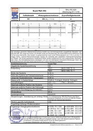
0,68 m<strong>Saferoad</strong> <strong>RRS</strong>Road Restraint Systems1,10 mPfostenabstand - variabeldistance of posts - variable0010-CPD-2009ErstprüfungInitial type test (ITT)EG-Konformitätszertifikat / HerstellerEU Certificate of Conformity / ManufacturerCharakteristisches Material des SystemsCharacteristic material of the systemBreite des Systems [m]Construction widthHöhe des Systems ab Fahrbahnoberkante [m]Construction height from roadway surface levelLänge der Systemelemente / -baugruppen [m]Length of system elementsMasse je lfd. m Systemlänge [kg/System]Weight per systemMaximale seitliche Position des Systems [m]Maximum lateral position of the systemMaximale seitliche Position des Fahrzeugs [m]Maximum lateral position of the vehicleMaximale dynamische Durchbiegung [m]Dynamic deflectionTestlänge [m]Test lengthGeprüfte Systemgründung / -aufstellungTested system foundation / installationBemerkungenRemarksErgänzende Angaben nach DIN EN 1317-2: 2011-0Additional information acc. to DIN EN 1317-2:2011-0Normalisierter Wirkungsbereich [m]Normalised working widthNormalisierte Wirkungsbereichsklasse WnClass of normalised working widthNormalisierte Fahrzeugeindringung [m]Normalised vehicle intrusionKlasse der Fahrzeugeindringung VIClass of vehicle intrusionNormalisierte dyn. Durchbiegung [m]Normalised dynamic deflectionTB11: 2002 / D 05/RK TB32: 2002 / D 06/RKsiehe gesonderte Übersichtsee separate overviewS235JR1.100.686.43307.901.67- - -0.646.43Gerammt rammed- - -- - -- - -- - -- - -Datenblatt · Data sheet<strong>Primus</strong> <strong>2a</strong>N2 · W5 · A© 2011 <strong>Saferoad</strong> <strong>RRS</strong> <strong>GmbH</strong>, Please note that forwarding this drawing without permission from <strong>Saferoad</strong> RSS <strong>GmbH</strong> is abreak of copyright. Please contact <strong>Saferoad</strong> RSS <strong>GmbH</strong> for information about corporate licences +49 30 212 491 11.Weight: 307.90 kg(Drawing no. K701020-1-1)
Allgemeine InformationenGeneral InformationsGeltende Vorschriften• RPS 2009• DIN EN 1317• Einsatzempfehlung der BASt• ZTV-SP 98• Einschlägige DIN NormenSymbolbedeutungTipp: Hinweise für Arbeitserleichterungenund effiziente Abläufe.Anforderungen an das MontagepersonalDie Montage darf nur durch geschultes und qualifiziertesFachpersonal durchgeführt werden. Montagefirmenerhalten bedarfsgerecht eine projektbegleitendetechnische Betreuung durch den Hersteller.Bestimmungsgemäßer GebrauchDas Rückhaltesystem ist zum Einbau in den Straßenverkehrsraumentsprechend den nationalen Bestimmungenvorgesehen. Es dient dem Schutz vonFahrzeuginsassen beim Abkommen eines Fahrzeugesvon der Fahrbahn, dem Schutz Dritter und dem Schutzvon Objekten und ist in Mittel- und Seitentrennstreifenbereichensowie am Fahrbahnrand einsetzbar.TransportBeim Transport ist Persönliche Schutzausrüstung (PSA– nach EG Richtlinie 89/686/EWG) entsprechend dennationalen Bestimmungen zu tragen. Transportieren Siedie Systemkomponenten mit einem LKW – gegen Verrutschender Ladung gesichert – auf die Baustelle. DiePakete können bis 2,8 t Gesamtgewicht haben und dieMaße L ≤ 4,35 m x B ≤ 1,00 m x H ≤ 1,00 m. Dementsprechendsind die Hebezeuge auszuwählen.ArbeitsschutzBeim Einbau ist Persönliche Schutzausrüstung (PSA– nach EG-Richtlinie 89/686/EWG) entsprechend dennationalen Bestimmungen zu tragen.Bei der Montage sind die entsprechend Punkt 3.3.2.angegebenen Montagetoleranzen zu beachten.Applicable Regulations• RPS 2009• DIN EN 1317• Application recommendations of BASt• ZTV-SP 98• Relevant DIN NormsSymbol DescriptionsTip: Information on facilitating work processesand efficient operations.Requirements of the Assembly PersonnelThe installation must only be undertaken by trainedand qualified personnel. Installation firms obtain aspecial technical advisor from the manufacturer tosupport the project.Usage ComplianceThe Restraint System is designed for installation onroad traffic areas according to national regulations. It isintended to protect occupants of errant vehicles on theroadway, to protect third parties and objective and canbe installed in central reserves and side lanes as well ason verges.TransportDuring transport, personal protective clothing (PPCin accordance with ER Guideline 89/686/EWG) mustbe used. When transporting the systems to the siteby truck, secure the load to prevent slippage. Thepackages can weigh up to 2.8t with dimensions ofL ≤ 4.35 m x ≤ 1.00 m x ≤ 1.00 m. Suitable liftingequipment must be used.Work ProtectionPersonal Protective Clothing (PPC in accordanceER Guideline 89/686/EWG) must be used accordingto national regulations.During installation, the assembly tolerances specified insection 3.3.2. must be adhered to.© <strong>Saferoad</strong> <strong>RRS</strong> <strong>GmbH</strong>, Stand 2011, Rev. 1
Technische InformationenTechnical InformationsSchraubverbindungenMuttern handfest anziehen und dann mit dem Drehmomentschlüsselfestziehen. Sämtliches Verschraubungsmaterialwird senkrecht zu den zu verbindenden Teilenangeordnet.Bolt ConnectionsFit nuts manually and then tighten with torque wrench.All fixtures to be fitted vertically to the connecting parts.Schraube · Bolt Mmin MmaxM 10 10 Nm 17 NmM 16 70 Nm 140 NmDauerhaftigkeitDie Mindestschichtdicke für Schrauben und Mutternbeträgt gemäß DIN EN ISO 10684 an den jeweiligenMessstellen 40 µm.DurabilityThe minimum coat thickness for screws and nutsshall be in accordance with DIN EN ISO 10684 at therespective measuring points 40 µm.Teile · ComponentsMittelwerte [µm]Average valueMindestwerte [µm]Minimum valueKonstruktionsteile · Construction Components 70 55Kleinteile (z.B. Decklaschen)Small Components (e.g. plate)55 45Erwartete DauerhaftigkeitCa. 20 Jahre, in Abhängigkeit von der atmosphärischenKorrosionsbelastung, z.B. Meeresluft,Industrieluft u.s.wExpected DurabilityApprox. 20 years, depending on atmospheric corrosione.g. maritime air, industrial air, etc.Bodenbedingungen, geeignete Gründungen · Soil coditions, suitable foundationsBodenklassennachDIN 18196Soil Class asper DIN 18196BezeichnungDescriptionEigenschaftenCharacteristicsRammenPost driving1 – 2 Oberboden, auch fließendSurface soil also fluid (Humus)Humus, Mutterboden,flüssig bis zäh flüssigtop soil, fluid to hardly fluidnicht möglich; Fundament erstellenNot possible3 – 5 Boden leicht lösbar,mittelschwer, schwerGround easily soluble heavySand- und Kiesböden mit Steinanteilbis 63 mm Korngrößemoderately heavy Sand and gravelsoil with stone content up to 63 mmgrain sizegeeignetpossible6 – 7 FelsRockFelsige Böden(und ab 63 mm Korngröße)Rocky ground(and from 63 mm grain size)nicht möglich; also bohren,einsetzen, verfüllen, verdichtenNot possible; therefore bore,fit, fill, pack© <strong>Saferoad</strong> <strong>RRS</strong> <strong>GmbH</strong>, Stand 2011, Rev. 1
Vorbereitende MaßnahmenPreparatory MeasuresSchutzausrüstung bereitstellen und anlegenStellen Sie folgende Persönliche Schutzausrüstungbereit und verwenden Sie sie bei den Einbau-Arbeiten:• Warnkleidung nach EN 471• Kopf-, Gehör-, Hand- und FußschutzWerkzeug bereitstellenDie hier genannten Werkzeuge sind erforderlich:• Pfosten-Ramm-Maschine• Handramme mit Schlauch + Bügelfür Kettenaufnahme• Pfostenzieher• Bohrmaschine bis 23 mm mit Bohrern• Wasserwaage/ Vorschlaghammer• Drehmomentschlüssel bis 140 Nm mit StecknüssenSie können sich jedoch die Arbeit durch den Einsatzvon alternativen und/oder zusätzlichen Werkzeugen,Geräten und Maschinen gegebenenfalls komfortablergestalten.Verkehr sichern, Baustelle vorbereiten/einrichtenFühren Sie die an Baustellen üblichen Verkehrssicherungs-Maßnahmennach den nationalen Bestimmungendurch. Die Baustelle muss Platz bieten für:• ausgelegte Systemkomponenten• Pfosten-Ramm-Maschine (-Gerät, z. B. Handramme)• LKWs mit Teleskop-Kran• Bewegungsfreiheit der MonteureLiefern, transportieren, auspacken, kontrollierenBringen Sie die Systemkomponenten mit dem LKW andie Einbaustrecke. Packen Sie sie aus und kontrollierenSie an Hand der Lieferscheine den Lieferumfang. BeiTransportschäden und/oder Mangel oder Fehllieferungenverständigen Sie unverzüglich den Spediteur/Lieferanten.Entsorgen Sie das Verpackungsmaterial entsprechendden örtlich geltenden Abfallentsorgungs-Bestimmungen.Laden Sie die benötigten Elemente mit demTeleskop-Kran neben der Einbaulinie ab.Allocate and wear protective clothingProvide the following personal protective clothing anduse during installation works:• reflective clothing as per EN 471• head, ear, hand and foot protectionAllocate toolsThe following tools are required:• Post rammer• manual rammer w. hose and bracket for chain fixture• Post pully• drill until 23 mm with drill bits• level / sledgehammer• torque key to 140 Nm with socketsHowever, you can facilitate the work by using alternativetools, equipment and machinery as necessary.Traffic Management, prepare site and set-upSet up the traffic management measures usuallyrequired by the national regulations. The constructionsite must have sufficient space for:• laid-out system components• post rammer (or equipment e.g. manual rammer)• truck with telescope crane• ample space for the assembly crewSupply, transport, off loading and delivery checkBring the system components by truck to the installationsection. Off-load and check that the delivery is asper the delivery docket. The carrier or supplier has tobe notified immediately if there is any transport damageor discrepancies with the delivery.Dispose of the packaging material according to theapplicable local refuse disposals regulations. Lift therequired guardrails with the telescope crane along theContainer with bolts, washers and nuts© <strong>Saferoad</strong> <strong>RRS</strong> <strong>GmbH</strong>, Stand 2011, Rev. 1
KontrolleInspection1. Überprüfen der KonstruktionNach dem Einbau des Rückhaltesystems prüfen Sieden festen Sitz aller Schraubverbindungen. Richten Siedas System ggf. nach. Überzeugen Sie sich, dass dieStrecke der Systemzeichnung entspricht.2. Einhaltung der Montagetoleranzensiehe Abbildung unten3. AbnahmeprotokollHalten Sie die Ergebnisse in dem in Anlagebeiliegenden Abnahmeprotokoll fest.4. Baustelle räumen, System freigeben• Räumen Sie alles Baumaterial und jeden Abfall weg.• Führen Sie eine Sichtkontrolle durch, ob die Einbaustreckevollkommen frei von Objekten ist.• Räumen Sie die Absperrungen ab und nach Abnahmemelden Sie dem Betreiber die Fertigstellung desSystems.1. Checking the assemblyAfter the installation of the road restrain system, checkthat all bolt fittings are tight. Align the system whereappropriate. Ensure that the section corresponds withthe system drawing.2. Maintaining the installation tolerancessee tab below3. Inspection reportMaintain the results in the Inspection Report enclosedin the attachment.4. Clear building site, approve system• Remove all building material andevery piece of refuse.• Carry out a visible inspection even if the installationroadway is perfectly free of objects.• Remove mobile safety barriers and after Inspection,report completion of the system to the Client.Einhaltung der Montagetoleranzen · Maintaining the installation tolerancesBezugsmaßReference MeasureAbstand der Pfosten in LängsrichtungPost spacing in longitudinal directionToleranz in cmTolerance in cm(+/-) 10 cmAnmerkungCommentOK PlankeTop of BeamOK KastenprofilTop of the Box ProfileSchrägstellung der AbstandhalterOblique position of the Spacer BarAbweichung Pfosten aus der FluchtPost deviation from alignmentAbweichung der Planke aus der FluchtBeam deviation from alignmentAbweichung des Kastenprofilsaus der FluchtBox Profile deviation from alignment(+/-) 10 cm Bezogen auf Geländehöheoder OK Kappe am PfostenpunktWith reference to height from road surfaceor top of curb at the post position(+/-) 10 cm Bezogen auf Geländehöheoder OK Kappe am PfostenpunktWith reference to height from road surfaceor top of curb at the post position5° in beide Richtungenin both directions3 cm auf 12 m Längeon 12 m section3 cm auf 12 m Längeon 12 m section3 cm auf 12 m Längeon 12 m section© <strong>Saferoad</strong> <strong>RRS</strong> <strong>GmbH</strong>, Stand 2011, Rev. 1
ÜberwachungsprotokollInstallation Control ReportInstalliertes Rückhaltesystem:Installed restraint system1. ausführende FirmaInstallation Company2. Lieferant des SystemsSystem Supplier3. AuftraggeberClient4. MontageortPlace of Assembling5.1. Verantwortlicher MontageleiterResponsible technical supervisorMonteureAssembly Team6. KontrollberichtInspection Report6.1. Vollständigkeit der Lieferung überprüftDelivery complete6.2. Eignung der örtlichen Bedingungen für den Einbau geprüftSuitability of local conditions for the installation checked6.3. Montageanweisung befolgtInstallation instruction followed6.4. Pfosten auf Einbautiefe gerammtRequired installation depth of the posts checked6.5. Verankerung (bei Plattenpfosten) überprüftAnchoring (for post with base plate) checked6.6. Pfostenabstände eingehaltenPost spacing observed6.7. Stöße der Holme ( Längselemente) überprüftJoints (longitudinal elements) checked6.8. Verschraubung auf Vollständigkeit kontrolliertBolt connections checked for completeness6.9. Geforderte Anzugsmomente der Schrauben angebrachtRequired torque of the bolts fitted6.10. Korrekter Einbau aller Elemente erfolgtProper installation of all elements followed6.11. Systemmaße ( Höhen, Abstand zum Fahrbahnrand etc. ) überprüftSystem dimension (height, distance to the verge etc.) checked6.12. Systemmaße ( Höhen, Abstand zum Fahrbahnrand etc. ) überprüftSystem dimension (height, distance to the verge etc.) checkedSonstige Bemerkung:Other observations7. Wetterbedingungen:Weather Conditions8. Abnahme durch Auftraggeber erfolgt ?Approval received from Client?Ort/Datum/UnterschriftPlace/Date/Signature+/-© <strong>Saferoad</strong> <strong>RRS</strong> <strong>GmbH</strong>, Stand 2011, Rev. 1
Anbringung von Zusatzeinrichtungenam SystemFitting additional safety devicesto the systemFür die Anbringung von zusätzlichen Einrichtungen derStraßenausstattung sind bereits Vorkehrungen an denElementen des Systems getroffen worden.VerkehrszeichenDie Montage von üblichen Verkehrszeichen ist auf demKastenprofile bzw. auf der verkehrsabgewandten Seitedes Kastenprofils an den Abstandhaltern oder Pfostenmöglich. Für die Befestigung sind die dafür bestimmtenVerkehrszeichenhalter zu benutzen. Dabei ist darauf zuachten, dass das so montierte Verkehrszeichen nicht inden Verkehrsraum ragt.FußgängerschutzFür das Anbringen des Fußgängergleitschutzes sindam Pfosten bereits entsprechende Befestigungspunktevorhanden. Gleiches gilt für den Zweiradfahrerschutzund das Anbringen eines Aufsatzgeländers.BlendschutzeinrichtungenDie Montage von Blendschutzeinrichtung ist auf demPfosten grundsätzlich möglich. Dort sind bereitsBohrungen für die üblichen Befestigungskonstruktionenvorhanden. Abhängig von der Art des Blendschutzeskönnen eventuell zusätzliche Bohrungen erforderlich sein.There are connection features on the system forattaching additional road safety devices.Trafic SignsThe assembly of common traffic signs is possible at therear of the guardrail beams in the box beam section i.e.on the spacer bar or posts. For attaching use the specifictraffic sign holders. If there is a danger that certaintraffic signs encroach into the traffic area, consultationwith the manufacturer regarding the positioning of thetraffic sign is required.Pedestrian ProtectionFor mounting pedestrian protection rails, correspondingmounting points are already available at the spacerbars. The same applies to motorcycle rails and thefitting of a vertical extension rail.Anti-glare systemsIt is possible to fit anti-glare systems onto the posts.Bolt holes are already located for the usual connectionfixtures. Extra bolt holes can be made depending onthe type of anti-glare systems.© <strong>Saferoad</strong> <strong>RRS</strong> <strong>GmbH</strong>, Stand 2011, Rev. 1
Reparaturen, Inspektionund WartungRepairs, Inspectionand MaintenanceReparaturenGrundsätzlich sind nur diejenigen Bauteile am Systemauszutauschen, die eine bleibende (plastische) Verformungaufweisen.Handelt es sich um nur unwesentliche, örtlich begrenzte,Verformungen an einem Bauteil, so ist einAustausch nicht unbedingt erforderlich. Sind Pfostenverbogen, so müssen diese ausgetauscht werden.Leichte Schrägstellungen der unverformten Pfostenkönnen nur dann durch Richten behoben werden, wennsich dadurch die Flucht der Längsprofile (Planke) wiederherstellen lässt.Ist ein bloßes Richten nicht möglich, und sind mehrereBauteile beschädigt, so ist im Bereich der Unfallstelledas System im modularem 4 Meter Raster komplettauszutauschen. Dabei sind alle demontierten Verbindungsmittel(Schrauben) durch neue zu ersetzen. Diehierbei entstandenen erweiterten Pfostenlöcher sind zuverfüllen und ausreichend zu verdichten.Außerdem ist darauf zu achten, dass Beschädigungenan den verzinkten Oberflächen vermieden werden.Kleine Fehlstellen an der Zinkoberfläche sind gemäßDIN 50976 nach sorgfältiger Vorbereitung durch auftrageneiner Zinkstaubbeschichtung nachzubessern.Überzähliges Material ist vollständig von der Reparaturstellezu entfernen.Reparaturarbeiten können durch jeden Fachbetriebproblemlos erledigt werden. Die einzelnen Bauteile fürReparaturarbeiten sind auf dem Markt frei erhältlich,wobei darauf zu achten ist, dass diese von einemCE-zertifizierten Hersteller stammen.Grundsätzlich sind bei der Durchführung von Reparaturarbeitendie Einbauanleitungen des Herstellers unddie Regelung der ZTV-PS98 Pkt. 2.4.2 zu beachten.Beschädigte Teile entsorgen / recyclenRecyceln Sie beschädigte Teile entsprechend den gesetzlichenund örtlichen Abfallentsorgungs-Vorschriften.Gefährliche und zu überwachende Substanzen sindnicht bekannt.Inspektion und WartungFühren Sie alle 12 Monate eine Sichtprüfung durch.Das System ist wartungsfrei.RepairsBasically, you need to replace only those componentsthat have any residual (plastic) deformation in thesystem.If these are merely minor deformations in one componentthat are local in nature, replacement is not reallynecessary. However, if posts are bent, they must bereplaced. Minor skews in the non-deformed posts canbe attended to by straightening or turning them, butonly if the alignment of the longitudinal section (plank)can be restored.If straightening or turning is not possible, and if morethan one component is damaged, the system in thedamaged section must be replaced completely usingthe modular 4 metre sections. In the process, all disassembledconnection fittings (screws) must be replacedwith new ones. The expanded holes in the posts resultingfrom this must be filled up and sealed adequately.Moreover, care must be taken to ensure that the galvanisedsurfaces do not get damaged. Minor defectivespots on the galvanised surface must be attended toby careful preparation with the application of zinc dustcoating in accordance with DIN 50976. Surplus materialmust be removed completely from the area that hasbeen repaired.Repair work can easily be undertaken by any contractor.The required components can be purchased on theopen market as long as they have the CE Mark of themanufacturer.The repair work must be undertaken according to themanufacturers installation specifications and the ZDV-PS98.2.4.2 Regulations.Dispose/recycled damaged componentsRecycle damaged parts according to legal and localwaste disposal regulations. There are no hazardousand dangerous substances.Inspection and MaintenanceRun every 12 months, a visual check.The System is maintenance free.© <strong>Saferoad</strong> <strong>RRS</strong> <strong>GmbH</strong>, Stand 2011, Rev. 1
Bedarfsanforderungen undAnpassungen an örtlicheBedingungenNecessary requirements andconforming to local conditionUmbauten des geprüften Rückhaltesystems in andererals der zuvor beschriebenen Bauweise sind ohne dieschriftliche Zustimmung des Herstellers nicht zulässig,da sonst die Zulassung nach DIN EN 1317 erlischt.PaßstückePaßstücke können auf der Arbeitsstelle angefertigtwerden. Dabei sind folgende Bedingungen während derHerstellung zu beachten:• Mindestlänge 750 mm auf der Arbeitsstelle(Profilüberlappung).• keine Überschreitung des vorgegebenen Pfostenabstandsder Schutzplankenkonstruktion beim Einbau,• fachgerechtes Trennen mit einer Trennschleifemaschineoder Säge,• fachgerechtes Bohren der Verschraubungslöcher,• fachgerechtes Nachbessern von Schnittstellen undgebohrten Verschraubungslöchern durch Auftragenvon Zinkstaubeschichtungsstoffen (DIN 50976).Der Einbau solcher Paßstücke ist auf ein Minimum zubeschränken. Nur in Ausnahmefällen (z.B. zwischen2 Brückenbauwerken) sind Paßstücke einzubauen.DilatationsstoßIm Bereich beweglicher Fahrbahnübergänge sindvorgesehene Dilatationsstöße symmetrisch einzubauen.Dabei muss beachtet werden, dass mit dem Einbauder Pfosten mit Fußplatte immer an der Bewegungsfugezu beginnen ist. Dilatationsstöße sollen stets fertigvormontiert auf der Baustelle angeliefert und mit demjeweils erforderlichen Pfostenabstand auf dem Bauwerkmontiert werden.Für die Einstellung der Dilatationsstöße ist die beimEinbau vorhandene mittlere Bauwerks-temperaturmaßgebend. Die Bewegung der Brücke infolge Temperaturänderungmuss beim Einbau der Pfosten bzw. dervorgefertigten Anker an der Dehnungsfuge berücksichtigtwerden.Für die Dilatationsstöße gelten + 10 °C als Nullstellung,bei der sich die Langlöcher gerade genau decken.Modifications to the tested restraint system are not permittedwithout the written confirmation of the manufactureras the approval to DIN EN 1317 would not be met.Cut piecesBeams can be cut to fit on site. The following conditionsmust be adhered to during production:• Minimum length 750 mm on site (beam overlap)• On installation the post spacing of the guardrailsystem must not be extended• Professional cuts using angle grinder or saw• Professional drilling for bolt holes• Professional re-work of cuts and drill holesusing zinc spray material ( DIN 50976 )• Keep the installation of cut pieces to a minimum.Only use them in exceptional circumstancessuch as between 2 bridge structures.Keep the installation of cut pieces to a minimum. Onlyuse them in exceptional circumstances such as between2 bridge structures.Heat Expansion jointIn section of movable road crossings, Heat ExpansionJoints have to be installed symmetrically. It is importantthat the installation of the base-plated posts alwaysstarts at the joint. Heat Expansion Joints should alwaysbe delivered to site fully assembled and installed on thestructure with the correct post spacing.The middle temperature of the structure at time ofinstallation is taken when setting the Heat ExpansionJoints. The bridge movement due to temperaturechanges must be taken into consideration wheninstalling the posts i.e. the pre-formed anchors at thejoint. Heat expansion Joint are always ready to preassembled,delivered and assembled on site with eachrequired post spacing on the structure.The Zero Position for overlapping the long bolt hole onHeat Expansion Joints is generally set at +10°C.© <strong>Saferoad</strong> <strong>RRS</strong> <strong>GmbH</strong>, Stand 2011, Rev. 1
Hierbei hat der Pfostenabstand genau 4000 mm(1333 - 1334 - 1333) zu betragen. Der beim Einbaumaßgebende Pfostenabstand ergibt sich somit aus derSystemlänge des Dilatationsstoßes von 4000 mm ±Längenänderung.Die Schrauben in den Dilatationsstößen dürfen nur sofest angezogen werden, dass keine Behinderung derLängsbewegung eintreten kann. Die Muttern sind fachgerechtzu kontern (Mindestanzugsmoment ca. 70 Nm).Bei Überbaulängen kleiner als 30 m kann auf Dilatationsstößeverzichtet werden. Auf langen Brücken mitgroßen Stützweiten, sollten mindestens alle 100 mDilatationsstöße zum Ausgleich der Spannungen vorgesehenwerden.Abweichender UntergrundBei der Verwendung auf nicht ebenerdigen Bankettenist die Lage der Systemlängselemente der Flucht derdurchlaufenden Schutzeinrichtung anzupassen.Abweichende EinbauhöheBei Bauwerkskappenhöhen > 7 cm erfolgt der Systemhöhenbezugzur Bauwerkskappe.Neigung des UntergrundsDas System ist auch im geneigten Bankett einsetzbar.Bei abfallendem Bankett sind ab einer Neigung von1:20 verlängerte Pfosten in Abhängigkeit der Neigungsstärkezu verwenden. Wird die zulässige Höhentoleranzdes Schutzplankenholms überschritten, müssenentsprechende Maßnahmen, wie die Verwendungeines zweiten untergehängten Schutzplankenholmeseinschließlich Abstandhalters vorgenommen werden.Grenzen vorgelagerter StufenVor- und nachlaufende Schutzeinrichtungen dürfen sichin der Aufhaltestufe maximal um eine Klasse unterscheiden.Radien, MindestradienIn Kurvenbereichen sind ab einem Radius von 30 mvorgebogene Schutzplankenholme zu verwenden. FürRadien von 50 m bis 10 m sind verkürzte Kastenprofile(z.B. 2 m) zu verwenden, die die entsprechende Radienführungzulassen. Bei Radien < 10 m sind vorgebogeneKastenprofile zu verwenden.Eingeschränkter WirkungsbereichWird der Wirkungsbereich durch bauliche Gegebenheiteneingeschränkt, ist der Regelabstand zwischenSystem und Verkehrsraum entsprechend den Empfehlungenzur RPS zu reduzieren.Post spacing must be exactly 4000 mm ( 1333 – 1334 –1333 ). The post spacing on installation is thereby givenfrom the system length of the Heat Expansion Joint of4000 mm ± longitudinal deviation.The bolts on the Heat Expansion Joint may only betightened to the extent that they do not interfere withthe longitudinal movement. The nuts must be counteredprofessionally (Minimum torque ca. 70 Nm).For installation lengths less than 30 m heat expansionjoint can be omitted. On longer bridges with large distancesbetween supports, heat expansion joint shouldmeet at least every 100 m to balance the tension.Uneven Ground ConditionsThe position of the system on uneven ground conditionsshould follow the alignment of the adjacentsystems.Uneven Installation SituationWhen building end kerbs > than 7cm, the height of thestructure has to be in reference with the building.Underground SlopeThe system can also be used on embankments. Onfalling embankments with a slope of more than 1:20,extended posts must be used in relation to the extentof the slope. If the system height is higher than thepermitted height tolerance, other measures must betaken such as fitting a 2nd guardrail beam with spacerbar underneath.Containment Level of adjacent systemsThe containment levels of adjacent safety barrier systemsmay only vary by one class.Radius, minimum radiusIn curved road sections of more than radius 30 m, prebendradius guardrails must be used. For radii between50m and 10m, shorter box beams (e.g. 2 m) must beused which meet the curvature. For radii < 10 m prebendbox beams must be used.Restricted Working WidthIt is a recommendation by in the RPS that if the workingwidth is limited due to structural obstructions, the regulatoryset-back between the safety barrier system andtraffic area should be reduced accordingly.© <strong>Saferoad</strong> <strong>RRS</strong> <strong>GmbH</strong>, Stand 2011, Rev. 1
Abweichender HöhenbezugWird das System in Plankenflucht < 10 cm zur Bauwerkskappenkantemontiert und ist die Höhendifferenzder Kappe zur FOK > 10 cm, ist der Systembezug aufdie FOK auszurichten.Anpassung des PfostenabstandesDer Pfostenabstand darf grundsätzlich nicht überschrittenwerden. Sollten die Baulichkeiten (z.B. Ablaufschächte)einen regelmäßigen Abstand nicht zulassen,darf das Pfostenraster mur verkürzt werden.Ausführung von VerschwenkungenIst auf Grund der baulichen Situation eine seitlicheVerschwenkung des Systems notwendig, sollte dieseim Verhältnis von 1:24 ausgeführt werden.Änderung von SystemteilenÄnderungen an Systemteilen sind mit dem Herstellerabzustimmen. Für geringfügige Änderungen wie Passstückeund zusätzliche Bohrungen sind die Regelungender ZTV-PS98 Punkt 2.4.2 zu beachten.Uneven Height ReferenceIf the barrier alignment of the system is installed< 10 cm from the edge of curb on the structure andthe height from finished road level to the curb is> 10 cm, then the height of the system is in respectof the finished road level.Adjustment of the post spacingIn principle, the distance between the posts are notexceeded. If the site conditions do not allow a regulardistance, the post spacing may be reduced.Installation of Flared EndsIf there are structural conditions where the terminalends must be flared back, the ratio should be 1:24.Modification of System ComponentsModifications to the system’s components must beagreed with the manufacturer. For minor modificationssuch as cut pieces and additional drill holes, the ZTV-PS98 Regulations, section 2.4.2 must be adhered to.Sonstige HinweiseOther InformationAuf Grund der abgestuften Systemhöhe ist das Systemproblemlos übersteigbar.As the system height for the guardrail beam is stepped,it can easily be mounted.© <strong>Saferoad</strong> <strong>RRS</strong> <strong>GmbH</strong>, Stand 2011, Rev. 1
EinbaubedingungenInstallation conditionsBeim Einbau des Systems sind die nachfolgenden Parameterzu prüfen und nach Möglichkeit einzuhalten. Dabeiist zunächst durch Messungen vor Ort festzustellen:A = Abstand Systemvorderkante vom Straßenrand – inder Regel A = 0,50 m. (Eventuell ist A an die Fluchtder übrigen Schutzeinrichtung anzupassen.)B = Länge des Hindernisses in (m).C = Abstand des Hindernisses (Vorderkante) vom befestigtenStraßenrand in (m).D = Abstand des Hindernisses (Hinterkante) vom befestigtenStraßenrand in (m).E = Entfernung der Böschungskante vom befestigenStraßenrand.When installing the system, the following paramatersmust be checked and the stated limit values observed, asfar as possible. In doing so, one must initially determine:A = Distance of the system’s front edge from the streetkerb – usually A = 0.50 m. ( It may be that A must beadapted to the alignment of the remaining protectiveinstallation.)B = Length of the obstacle in (m).C = Distance of the obstacle (front edge) from the fixedstreet kerb in (m).D = Distance of the obstacle (back edge) from the fixedstreet kerb in (m).E = Distance of the slope edge from the fixed streetedge.3.1. StandardausführungIn der Standardausführung hat das System eine Längevon L = 6,40 m und besteht aus zwei spiegelbildlich zueinanderangeordneten Halbelementen. Diese werden aufje zwei getrennten C - Pfosten so aufgeschraubt, dassdas System symmetrisch zum Hindernis steht.3.1. Standard versionIn the standard version, the system has a length of L =6.40 m and consists of two half-elements arranged inmirror symmetry to one another. These are both respectivelyscrewed onto two separated C-posts in such a waythat the system stands symmetrically to the obstacle.Befinden sich die Maße im Rahmen der vorgegebenenGrenzwerte, so kann das System inder Standardausführung Fig. 1 errichtet werden.Sind die Maße außerhalb der Grenzwerte somuss das System in der gestreckten AusführungFig. 2 errichtet werden.If the dimensions are within the pre-definedthreshold values, the system can be set up inthe standard version (see Fig. 1). If the dimensionsare outside the threshold values, the systemmust be set up using the stretched version (seeFig. 2).B ≤ 2.00 mC ≥ 1.00 mD ≤ 2.50 mAL = 6.40 m© <strong>Saferoad</strong> <strong>RRS</strong> <strong>GmbH</strong>, Stand 2011, Rev. 1
3.2. Gestreckte AusführungSind breitere Hindernisse vorhanden B > 2m oder stehendiese weiter vom Straßenrand entfernt D > 2,5 m, soist das System mit einer Doppelholm-Verlängerung (L V)symmetrisch zur Mittelachse zu versehen.3.2. Stretched versionIf wider obstacles are present (B > 2m) or these are locatedfurther away from the street kerb (D > 2.5 m), thesystem must be given a double-beam extension ( L v)symmetrically to the middle axis.L 3lBL 3rD≤ 5DL V3.20 m 3.20 mDie Werte der Tab. 1 können sich reduzieren, wenn derAbstand des Systems vom Straßenrand (Maß A) vergrößertwird, das System also näher an das Hindernisheranrückt.The values of Tab. 1 can reduce if the distance of thesystem from the street kerb (Measurement A) is increased,i.e. the system is moved closer to the obstacle.D [in m] 2.5 3.0 3.5 4.0 5.0L V[in m] 4.0 8.0 12.0 16.0 20.0L 3[in m] 4.0 5.6 7.6 10.0 13.01. Länge ( D ) und Breite ( B ) der Hindernisse durch Messungenbestimmen.2. Maß A mit 0,5m oder in Flucht mit anderen Schutzeinrichtungenfestlegen.3. Den Abstand des <strong>Primus</strong> vom äußeren Hindernis (MaßL 3) nach Tab. 1 bestimmen. Der Abstand L 3kann linksund rechts jeweils verschieden sein.1. Determine length (D) and width (B) of the obstacles bymeans of measurements.2. Set Measurement A at 0.5 m or in alignment with otherprotective installations.3. Determine the distance of the <strong>Primus</strong> from the externalobstacle (Measurement L 3) acc. to Tab. 1. L 3can bedifferent on the left side and on the right side respectively.Die Länge L Vist nach folgender Regel zu bestimmen:The length Lv must be determined according to the followingrule:L V= B + L 3l+ L 3r- 6.40 [in m]Die Länge L 3ist jeweils vom Maß D abhängig, kann alsoam rechten L 3rbzw. linken L 3lEnden verschieden sein.Für die Holm-Verlängerung sind ausschließlich Bauelementenach Zeichnung Z.20.13 zu verwenden.The respective length (L 3) is dependent on MeasurementD; it can thus be different at the right end L 3ror at theleft end L 3lrespectively. For the extension of the beamit is exclusively construction elements according to thedrawing Z.20.13 which must be used.© <strong>Saferoad</strong> <strong>RRS</strong> <strong>GmbH</strong>, Stand 2011, Rev. 1
<strong>Saferoad</strong> <strong>RRS</strong>Road Restraint SystemsStückliste · Components list0010-CPD-2009NameArtikel Nr.Part no.Anzahl/StückNumber/Unit<strong>Primus</strong> <strong>2a</strong> Einzelkörper · Chassis 492508/2 2Pfosten · Post C 125 1900 mm 406102/0 4<strong>Primus</strong> Bügel · Bracket 492510/0 1Decklasche · Plate 2x M16 492545/0 1HRK-Schraube · Bolt M16x27 040.00 12HRK-Schraube · Bolt M16x40 040.01 12Scheibe · Washer Ø 18 040.30 16Scheibe · Washer 40x18x4 mm 040.31 8Montagetafel · Assembly drawingMegaRail <strong>Primus</strong> <strong>2a</strong>N2 · W5 · A© 2011 <strong>Saferoad</strong> <strong>RRS</strong> <strong>GmbH</strong>, Please note that forwarding this drawing without permission from <strong>Saferoad</strong> RSS <strong>GmbH</strong> is abreak of copyright. Please contact <strong>Saferoad</strong> RSS <strong>GmbH</strong> for information about corporate licences +49 30 212 491 11.Weight: 307,90 kg(Drawing no. K701020-3-1)
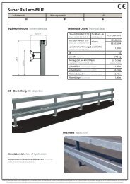
<strong>Saferoad</strong> <strong>RRS</strong>Road Restraint SystemsVorderansicht · Front viewRückansicht · Rear view0010-CPD-20093D Darstellung · 3D depictionMegaRail <strong>Primus</strong> <strong>2a</strong> bsN2 · W5 · A© 2011 <strong>Saferoad</strong> <strong>RRS</strong> <strong>GmbH</strong>, Please note that forwarding this drawing without permission from <strong>Saferoad</strong> RSS <strong>GmbH</strong> is abreak of copyright. Please contact <strong>Saferoad</strong> RSS <strong>GmbH</strong> for information about corporate licences +49 30 212 491 11.Weight: 307,90 kg(Drawing no. K701020-2-1)
EG-Konformitätserklärung · EU-Declaration of Conformitynach Bauproduktenrichtlinie 89/106/EWG für das RückhaltesystemIn accordance with building product code 89/106/EWG for restraining systems<strong>Primus</strong> <strong>2a</strong>0531Der HerstellerManufacturererklärt hiermit, dass folgendes Produkt:declares herewith that the following productOutimex AGLandshuter Straße 1,10779 Berlin/ Germany„<strong>Primus</strong> <strong>2a</strong>“Fahrzeugrückhaltesystem im StraßenverkehrsraumRoad Restraint Systemden Bestimmungen der oben gekennzeichneten Richtlinie entspricht.complies with the above named Regulations.ZertifizierungsstelleCertification BodyEU-NotifizierungsnummerEU-Notification numberBeschreibung des ProduktsProduct DescriptionVerwendungshinweisApplication NoteEG-Konformitätszertifikat-Nr.EU-Certificate of Conformity No.Folgende Europäische Normen wurden angewandtThe following European Norms applyTÜV SÜD SZA ÖsterreichTechnische Prüf-<strong>GmbH</strong>Arsenal Objekt 2071030 Vienna/ Austria0531Aufhaltestufe Containment Level N2Anprallheftigkeit Impact Severity AWirkungsbereich Working Width W5Dynamische Durchbiegung Dynamic Deflection 0,6 mDas Rückhaltesystem „<strong>Primus</strong> <strong>2a</strong>“ ist ein Anfahrschutzfür einzelne Hindernisse im Straßenraum. Als kurzeSchutzeinrichtung kommt es bevorzugt dort zumEinsatz, wo die örtlichen Verhältnisse keine durchgehendenSchutzeinrichtungen zulassenThe restraint system “<strong>Primus</strong> <strong>2a</strong>” is an impact protectionsystem for individual hazards in verges. As a shortsafety system, its is preferably used in such locationswhere it is not possible to use a continuous installation.0010 - CPD - 2009EN 1317 Teil 1,2 und 5Hilmar FörsterTechnischer VorstandTechnical Menber of the BoardHolger KlostermeierLeiter F&EHead of R&D
<strong>Saferoad</strong> <strong>RRS</strong> <strong>GmbH</strong>Sales International<strong>Saferoad</strong> <strong>RRS</strong> <strong>GmbH</strong>Sales GermanyLandshuter Straße 110779 BerlinT + 49 30 21 24 91 11F + 49 30 21 24 91 50berlin@saferoad.comBongard-und-Lind-Straße 156414 WerothT + 49 6435 90 80 0F + 49 6435 90 80 110weroth@saferoad.com© <strong>Saferoad</strong> <strong>RRS</strong> <strong>GmbH</strong>, Stand 2011, Rev. 1www.saferoad-rrs.comwww.produktmatrix.dewww.downloadhub.de