SW4000 USER MANUAL - Nilfisk PARTS - Nilfisk-Advance
SW4000 USER MANUAL - Nilfisk PARTS - Nilfisk-Advance
SW4000 USER MANUAL - Nilfisk PARTS - Nilfisk-Advance

Erfolgreiche ePaper selbst erstellen
Machen Sie aus Ihren PDF Publikationen ein blätterbares Flipbook mit unserer einzigartigen Google optimierten e-Paper Software.
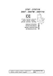
ENGLISH<strong>USER</strong> <strong>MANUAL</strong>FUSE CHECK/REPLACEMENT/RESET1. Drive the machine on a level ground and engage theparking brake.2. Turn the ignition key (61) to “0”.3. Open the engine compartment hood (18) with the handle(41) and fasten it with the support rod (53).4. Disconnect the negative connector (-) of the batteries (46).A H L K J I N M HLamellar Fuse Check/Replacement5. Remove the fuse box cover (A, Fig. 25).6. Check/replace the relevant fuse among the following (Fig.26):• (B): F1 vacuum system motor fuse (30 A).• (C): F2 filter shaker motor fuse (30 A).• (D): F3 display electronic board fuse (3 A).• (E): F4 main fuse (key circuit) (10 A).• (F): F5 dust guard system fuse (5 A) (optional).• (G): F6 hopper lifting fuse (30 A).7. Remove the screws (H, Fig. 25), then remove the cover (I)of the electrical component box (50).8. Check/replace the following fuses:• (J): FA main broom motor fuse (50 A).• (K): F0 main fuse (150 A).• (L): FC battery charge fuse (80 A).Fuse Check9. Check one of the following fuses (Fig. 25) for deactivation:• (M): FR1 right side broom motor fuse (15 A).• (N): FR2 left side broom motor fuse (15 A) (optional).Reset any deactivated fuse, when the component thatcaused deactivation has fully cooled down.Reassembly10. Connect the negative connector (-) of the batteries (46).11. Remove the support rod (53) and close the hood (18).30A5A10A3A30A30AFigure 25GFEDCP100609P-LPGSAFETY FUNCTIONSThe machine is equipped with the following safety functions.Figure 26BP100610P-LPGEMERGENCY PUSH-BUTTONIt is to the left side of the operator (77). It has to be pressed in case of emergency, to stop all the machine functions.DRIVER’S SEAT MICROSWITCHIt is located inside the driver’s seat (3) and it does not allow the machine drive system to operate if the operator is not seated on thedriver’s seat.HOPPER POSITION SENSORWhen the hopper is lifted, the sensor reduces the machine speed, turns off the vacuum fan and stops the broom rotation.HOPPER SAFETY VALVEWhen the hopper is lifted, the safety valve on the hydraulic lifting cylinder prevents the hopper to accidentally lower.34 <strong>SW4000</strong> - 1464815000