HC100ML-2 HC500ML-2 - Chamberlain
HC100ML-2 HC500ML-2 - Chamberlain
HC100ML-2 HC500ML-2 - Chamberlain

Sie wollen auch ein ePaper? Erhöhen Sie die Reichweite Ihrer Titel.
YUMPU macht aus Druck-PDFs automatisch weboptimierte ePaper, die Google liebt.
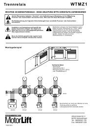
INFRARED SENSOR 9 AThe infrared sensor is a safety-enhancing facility and must be used.Its installation location depends on the design of the given slidinggate. Generally speaking, the light barrier is fitted at knee heightapprox. 35cm above ground level. Infrared sensors comprise atransmitter element and a receiver element which have to be locatedopposite one another. A screwdriver can be used to open the lightbarrier housing (plastic). The infrared sensor is fitted to the wall withsmall screws and wall plugs. Usage of a single infrared sensor is aminimum requirement; we recommend using two infrared sensors(and other safety features if necessary).Should a further infrared sensor be active for the OPEN direction oftravel, it has to be connected to contact 11 + 12 (stop). This isnecessary if the area behind the gate has to be secured. If contactstrips (accessories) are to be employed as additional safety features,they also have to be connected to the stop contact.The transmitter element needs a 2-pole cable, the receiver element a4-pole one.Cable cross-sectional area: 0.5mm 2 or more.Voltage: 12/24 volt AC/DC.Electrical connections: See control unit instructions.TECHNICAL DATAVoltage INFrequencyPowerCurrent ratedTorqueCapacitorTherminal OverloadProtectionMotor SpeedTravel SpeedDuty CycleWorking TemperaturRangeProtection ClassDegree of ProtectionWeightapprox. Gate LengthMax. Gate weight atmax. length (incl.20% reserve)HC100230Volt50Hz300W1.3A9Nm814014001230-20 O C - 55 O CIP44I95m300kgHC500230Volt50Hz360W1.5A10Nm1014014001230-20 O C - 55 O CIP44I98m500kgGB-3FLASHING LAMP 10 - 11Usage of a flashing lamp is mandatory. It serves a safety-relatedpurpose in that it warns persons in the vicinity of the gate that thegiven gate is moving.The flashing lamp is fixed in position using screws and wall plugs.The earthed cable has to be run up to connect with the lamp.Normally speaking, it is installed at the highest possible point(on a pillar).Cable cross-sectional area: 0.75mm 2 , 3-poleVoltage: 230 volt/AC.Electrical connections: See control unit instructions.KEY SWITCH (OPTIONAL)The key switch can be used to activate the drive as well as open andclose the gate. Cable cross-sectional area: 0.5mm 2 or more.Electrical connections: See control unit instructions.INSTALLATION OF AN EXTERNAL ANTENNA (OPTIONAL)An external antenna is not a mandatory requirement. A short antennais located on the control unit's radio adapter. Should the range of theremote control need to be extended, fit an external antennacompatible with 433 MHz (the ANT4X-EML model incl. 750 ohmcoaxial cable). It has to be connected up via the radio adapter on thecontrol unit (see control unit instructions). The best location for anantenna is high up and as far away from electrical equipment aspossible. The short cable antenna that is supplied as standard andpre-connected may then no longer be used.Electrical connections: See control unit instructions.INITIAL OPERATIONCheck gate functionality manually when the drive has beendisengaged. Electrical operation is only possible with the control unitthat is supplied as standard.Electrical connections: See control unit instructions.Always ensure that the mechanical and electrical safety requirementsrelevant to the given system are complied with.MAINTENANCE WORK 12The drive mechanics are maintenance-free. Check at regularintervals (monthly) that the gate hardware and the drive are all firmlyin place. Disengage the drive and check gate functionality. Only aneasy-running gate will work well with a drive. A drive is no substitutefor a poorly functioning gate.A sliding gate can also be secured by implementing on-sitemeasures (fence, wall, etc.). See fig. 12.709207B-GB - 05.2004TECHNICAL DATA - CONTROL UNITVoltage:230V~ ±10% 50HzMax. consumption:10WMax. drive supply:230V~ 50Hz 700VA maxInfrared Sensor supply:24V~ 0,5A maxWorking temperature:-25 O C – 55 O COperating modes:Automatic / Semi-automatic / Step-by-step / Dead manMax. running time:120 secPause period:8 – 200secDimensions:109x145mm (without box)ELECTRICAL INSTALLATIONThe control unit is designed to be installed in a special boxunder the hood of the sliding gate drive and, as such, can beordered as an accessory if not already available. The controlunit can also be accommodated externally (on the wall) in awatertight box (accessory).The control unit should be the last item to be connected up, i.e.mounting the drive, laying the necessary cable and fitting lightbarriers (contact strips). If installation is to be performed in apermanent location, a means of disconnecting the equipment fromthe mains supply with a contact clearance of at least 3 mm is needed(master switch). Humidity and water will destroy the control unit.Always make sure that water, humidity and condensation cannotenter the control unit. It is vitally important that all openings and cableglands are sealed so that they are watertight.INSTALLATION OF CONTROL BOXThe motor control unit is a microprocessor-controlled electronicappliance featuring state-of-the-art technology. It is equipped with allthe connecting options and functions needed to guarantee safeoperation. The control box incorporating the motor control unit shouldbe installed with the cable intakes pointing downwards. It should notbe continuously exposed to direct sunlight. The electronic equipmentenables the pull and push forces to be set with great accuracy. Ifinstalled and set correctly, the gate can be stopped manually.When in motion, the gate can be stopped at any time by operatingthe remote control, the push-button or the key-operated switch.The gate must be fitted with a robust end stop for the OPEN andCLOSED positions.Generally speaking, the following minimum cable crosssectionalareas must be adhered to:• 100-230Volt 1,5mm 2 or more• 0-24Volt 0,5mm 2 or moreTips: Bell wire is often problematic in practical use because it losestoo much voltage if long lengths of wire are used.Segregate the cables in cable trunking, i.e. motor cable and lightbarrier cable, especially in the case of key-operated switches and ONswitches (from the house wiring system) to prevent interferencewhere long lengths of cable are used.