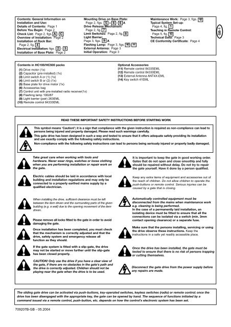
Contents: General Information onInstallation and Use:Details of Contents: Page 1Before You Begin: Page 2Check List: Page 2, figs. A - COverview of Installation: Page 2Installation of Rack Bar:Page 2, fig. 4Electrical Installation: figs. 2 - 3Installation of Base Plate: Page 2Mounting Drive on Base Plate:Page 2, figs. 5 + 6 - 6 ADrive Release Mechanism:Page 2, fig. 7Limit Switches: Page 2, fig. 8Light Barrier:Page 3, figs. 9 AFlashing Lamp: Page 3, figs. 10 - 11External Antenna: Page 3Initial Operation: Page 3Maintenance Work: Page 3, figs. 12Typical System Set-up:Page 4, fig. 1Teaching in Remote Control:Page 5, fig. 13Technical Data: Page 3CE Conformity Certificate: Page 4GB-1Contents in HC100/HC500 packs(1) Drive motor (1x)(2) Capacitor (pre-installed) (1x)(3) Limit switch A or (1) (1x)(4) Limit switch B or (2) (1x)(5) Base plate for drive motor (1x)(6) Accessories bag(7) Control unit with pre-installed radio receiver(1x)(8) Flashing lamp 100287(9) Light barrier (pair) 263EML(10) Remote control 84333EMLOptional Accessories(11) Remote control 84335EML(12) Remote control 84330EML(13) External Antenna ANT4X-EML(14) Key switch 41EMLREAD THESE IMPORTANT SAFETY INSTRUCTIONS BEFORE STARTING WORKThis symbol means 'Caution!'; it is a sign that compliance with the given instruction is required as non-compliance can lead topersons being injured and property damaged. Please read such warnings carefully.This gate drive has been designed in such a way and tested to ensure that it offers adequate safety providing its installationand use exactly comply with the following safety instructions.Non-compliance with the following safety instructions can lead to persons being seriously injured or property badly damaged.Take great care when working with tools andhardware. Never wear rings, watches or loose clothingwhen you are performing installation or repair work onthe gate.Electric cables should be laid in accordance with localbuilding and installation regulations and may only beconnected to a properly earthed mains supply by aqualified electrician.It is important to keep the gate in good working order.Gates that do not open and close smoothly and fullyshould be repaired without delay. Do not try to repairthe gate yourself. Have it done by a person qualified.Keep any extra items of equipment and accessories out ofthe reach of children. Do not allow children to operate thepush-buttons or remote control. Serious injuries can becaused by a gate that is closing.When installing the drive, sufficient clearance must be leftbetween the item driven and the surrounding parts of the givenbuilding (e.g. a wall) due to the opening movement of the itemdriven.Please remove all locks fitted to the gate in order to avoiddamaging the gate.Once installation has been completed, you must checkthat the mechanism is correctly adjusted and that thedrive, safety system and emergency release allfunction as they should.If the gate system is fitted with a slip-gate, the drivemay not be started or move further until the slip-gatehas been closed properly.CAUTION! Only use the drive if you have a clear view ofthe gate, if there are no obstacles in the gate's path andthe drive is correctly adjusted. Children should not beplaying near the gate when the drive is to be used.Automatically controlled equipment must bedisconnected from the mains when maintenance worke.g. cleaning is being performed.In the case of a permanently laid installation, anisolating device must be fitted to ensure that all theconnections can be isolated via a switch (min. 3mmcontact opening clearance) or a separate fuse.Make sure that the persons installing, servicing or usingthe drive observe these instructions. Keep theinstructions in a safe yet readily accessible place.Once the drive has been installed, the gate must betested to ensure that there is no risk of persons trappingor cutting themselves.Disconnect the gate drive from the power supply beforeany repairs are made.The sliding gate drive can be activated via push-buttons, key-operated switches, keyless switches (radio) or remote control; once thedrive has been disengaged with the appropriate key, the gate can be opened by hand. The sequence of functions initiated by acommand issued via a remote control, push-button, etc. depends on how the control's electronic system has been set.709207B-GB - 05.2004
BEFORE YOU BEGINThere are many factors that are key to the choice of the rightsliding gate drive. Assuming the gate is in good working order, themost difficult aspect is getting the gate to move. Once the gate is inmotion, force requirements are in the main significantly reduced.• Gate size: Gate size is a very important factor. A light yet longgate (long = + 5m) needs a far greater force to set it in motionthan a short, heavy gate does.WIND CAN BRAKE A GATE'S MOVEMENT OR MAKE IT HARDTO MOVE, THUS INCREASING FORCE REQUIREMENTSSIGNIFICANTLY.• Gate weight: Gate weight is only an approximate indicator theactual relevance of which can vary greatly. Example: A light gatethat slides poorly is likely to need a stronger drive than aheavy, smooth-sliding gate.• Temperature: Low outdoor temperatures make it difficult or, insome cases, impossible to get the gate moving due, for instance,to changes in the ground conditions. In such cases, a strongerdrive again might be necessary. High outdoor temperatures cancause the thermal protection mechanism to be activated sooner.• Operating frequency / Duty cycle: Sliding gate drives have amaximum duty cycle of approx. 30% (e.g. 30% per hour). CAUTION:The drives were not designed to be run for the maximum duty cycleon a regular basis (permanent operation). If the drive gets too hot, itswitches itself off until it has cooled down to activation temperature.The outdoor temperature and the gate itself are key factorsdetermining the drive's actual duty cycle• Safety: A sliding gate drive has to be fitted with a flashing lamp,contact strips and, if necessary, with additional light barriers as safetyfeatures. Please ensure that you comply with the standards andregulations relevant to your particular case.• Control unit: The control unit was developed specifically withsafety aspects in mind. It is already located under the drive hoodand wired up for right-hand installation as standard (motor to theright of the gate). See figs. 2 - 3.CHECK LIST - PRE-INSTALLATION WORK A - CPrior to actual installation, please check that you have been providedwith all the parts indicated within the scope of supply.Make sure your gate system is in good working order.The gate must run smoothly, not jerkily and not make contact withthe ground at any point. Bear in mind that the ground can be severalcentimetres higher in winter. The gate needs to be stable with as littleplay as possible to prevent any lateral movement from occurring. Theeasier the gate moves, the more sensitive the force setting needs tobe.Make a note of the materials you still need and make sure you obtainthem prior to installation - adhesive anchors (strong plugs), screws,stops, cable, distributor boxes, tools, etc.OVERVIEW OF INSTALLATIONA general overview of installation can be found on the front sheet ofthese instructions. The drive has to be installed behind the wall toensure that no part of it projects out into the gate opening. The motorhas to be mounted on the flush fitted base plate. The rack bar shownhas to be fitted to the gate with the fixing material supplied.Decide which is the best height for fixing the rack bar to the gate anduse this to determine the installation dimensions for the motor unitand base plate. Should the gate be unsuitable for fitting the rack barto it, a fixing profile (angle bracket, shaped tubing, etc.) needs to bemounted first.709207B-GB - 05.2004INSTALLATION OF DRIVE BASE PLATE 5 - 6 AThe base plate for the drive can either be concreted in or, if appropriate,welded into position. The place where the base plate is usually locatedis shown on the installation overview. The concrete plinth needs to be ofan appropriate size (approx. 50cm x 50cm x 50cm).Please note: If it is impossible to precisely determine the height ofthe plinth and the distance from the gate prior to installation, it isadvisable to mount the rack bars first and then concrete in the baseplate. Spacers are fitted to move the rack bars approx. 40mmtowards the inside.The distance from the bottom edge of the rack bar to the base plateis approx. 8 - 9cm. The base plate permits final height and depthadjustments of several centimetres to be made, but you are advisedto work as precisely as possible from the outset.MOUNTING MOTOR AND GEAR UNITThe drive should be fitted on to the threaded bolts in the base plate.The height should be set such that there is a gap of approx. 1 - 2mmbetween the cog wheel and the rack bar. The weight of the gate shouldnot be borne by the cog wheel! Position the drive via the adjustmentholes such that its location vis-à-vis the rack bar complies with theinstallation dimensions.MOUNTING RACK BAR 4The easiest way to fit the rack bar is to first place it on the motor'sdrive cog, disengage the motor and, by pushing the gate further withthe rack bar, screwing the bar bit by bit firmly in position. In this way,you ensure that the rail bar engages with the cog wheel in an optimummanner. While doing this, do not forget to mark each fixing point.DRIVE RELEASE MECHANISM (MANUAL OPERATION) 7The drive is equipped with a lockable release mechanism to enablethe gate to be operated manually in a power cut. The releasemechanism is shown in fig. 7 with the clutch disengaging the linkbetween the cog wheel and the gear.To release the drive: Position the socket spanner appropriately andturn it 180 degrees. Then turn the release lever 180 degrees too.Finished.FITTING LIMIT SWITCHES (TO GATE) 8The limit switches are assembled as shown in fig. 8.One limit switch magnet is designated A (1) and the other B (2).Fit the limit switches on to the rack bar in those places where thefinal travel positions are roughly expected to be. The magnet shouldpoint towards the motor. The switch (contact) is located in the middleof the motor. Screw the retaining clip only provisionally in place orslot it lightly on to the rack bar.Limit switch A (1) for gate closed; limit switch B (2) for gateopen.TESTING LIMIT SWITCH FUNCTIONALITY(CHAMBERLAIN-CONTROL)Disengage the gate and operate it only using your hands. Push thegate into the respective final travel positions. The control unit shouldalready have been connected up.On the control unit there are two red LEDs (LED 5 & LED 6) that goout when the magnet on the gate trips the given switch. One LED isfor limit switch OPEN (LED 5) and the other for CLOSED (LED 6).When you open the gate manually, the correct LED should go out. Ifthe wrong LED goes out, you need to swap limit switches A (1) andB (2) around. Alternatively, the limit switch cables connected to thecontrol unit (17 + 19) can be swapped around. The distance betweenthe limit switch magnet and the switch on the drive should be assmall as possible. Under no circumstances should it be more than25mm.Important: If the limit switches have been swapped around, the gatewill open and not close after the set pause when in programmeselection (automatic) mode!Caution: A sliding gate must run in a guide rail and should notbe able to leave the rail. This means end stops need to be fittedfor both directions!GB-2