Türcodegerät 421-30-10 - Ikon
Türcodegerät 421-30-10 - Ikon
Türcodegerät 421-30-10 - Ikon
- Keine Tags gefunden...

Sie wollen auch ein ePaper? Erhöhen Sie die Reichweite Ihrer Titel.
YUMPU macht aus Druck-PDFs automatisch weboptimierte ePaper, die Google liebt.
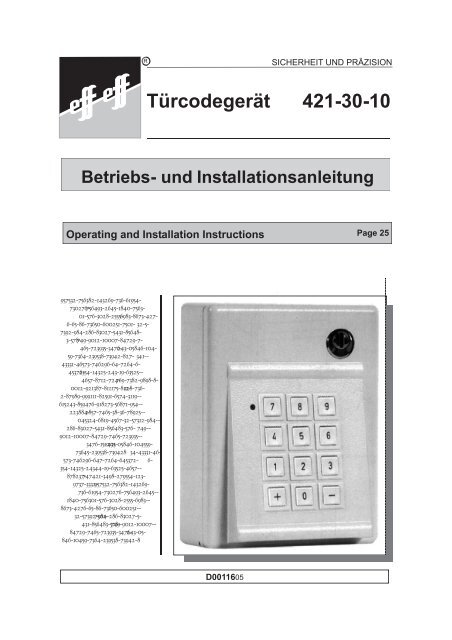
Gerätefunktion und Bedienung.Allgemeiner Funktionsablauf.Das Gerät dient dazu, die Benutzung einer Tür auf einenbestimmten Personenkreis einzuschränken. Dies wird dadurcherreicht, daß die Freigabe der Tür von einem Zahlencode abhängiggemacht wird, welcher im vorliegenden Gerät mit einer Länge vonzwei bis sechs Stellen frei programmiert werden kann. Wird dieprogrammierte Zahl an der Tastatur des Türcodegerätseingegeben, so wird für eine einstellbare Zeit der Elektrotüröffnerangesteuert, sodaß die Tür geöffnet werden kann. Spätestens nachAblauf der eingestellten Zeit wird die Ansteuerung des Türöffnerswieder abgebrochen. Die danach wieder ins Schloß fallende Tür istdann wieder gesperrt.Programmierbare Codes.Das Gerät kann maximal vier verschiedene gleichzeitig geltendeCodes verwalten. Drei dieser Codes -die "Benutzercodes" - könnenjederzeit wieder gelöscht werden, während der im folgenden"Hauptcode" genannte Code nur überschrieben werden kann. DerHauptcode unterscheidet sich von den Benutzercodes außerdemnoch darin, daß er alleine berechtigt ist, eine Dauerentriegelungeinzuleiten oder wieder aufzuheben. Jeder Code besteht aus einerbeliebigen Zahl zwischen 00 und 999999. Die Stellenzahl desCodes kann ebenfalls beliebig gewählt werden. Dies bedeutet, esgibt für jeden Code 1.111.<strong>10</strong>0 verschiedene Möglichkeiten. (Übereinige funktionsbedingte Einschränkungen finden Sie näheres imAbschnitt "Programmieranleitung".)DauerentriegelungÜber den Hauptcode kann vom Türcodegerät <strong>421</strong>-<strong>30</strong>-<strong>10</strong> auch eineDauerentriegelung ausgelöst werden. Dazu wird vor Eingabe derCodezahl die Taste + betätigt. Dies bewirkt, daß der Relaiskontaktso lange angezogen bleibt, bis der Hauptcode erneut eingegebenwir mit vorheriger Betätigung der Taste - .6
Dieser Zustand des Geräts kann äußerlich selbstverständlich nichterkannt werden und läßt sich auch nicht zurücksetzen ohne dasGerät zu öffnen.Die Anzahl der zulässigen Falscheingaben bis zur Sperrung derTastatur ist abhängig von den jeweils programmierten Codes. Siebeträgt das doppelte des längsten im Gerät aktuell programmiertenCodes plus eins. Ist also beispielsweise ein sechstelligerHauptcode programmiert, so muß bei einem Eingabeversuchspätestens mit der dreizehnten Tastenbetätigung ein gültiger Codein voller Länge eingegeben sein. Anderenfalls tritt eineTastatursperrung ein.Bedienung und Anzeigefunktion.Die Bedienung des Geräts ist bewußt einfach gehalten underfordert keine besondere Instruktion der einzelnen Benutzer. DasGerät ist im Normalzustand ständig in Bereitschaft. Der Code kanndirekt eingegeben werden. Nach Codeeingabe zieht unverzögertder Ausgangskontakt an - die Tür kann geöffnet werden. DasAnziehen des Kontaktes wird durch die grüne Leuchtdiodesignalisiert, die so lange aufleuchtet, wie der Kontakt angezogenbleibt.8
Er wird umprogrammiert, indem nach dem Einschalten desProgrammiermodus einfach die gewünschte neue Hauptcode-Ziffernfolge an der Eingabetastatur eingetippt wird.Programmierung der BenutzercodesFür spezielle Anwendungen können im Türcodegerät <strong>421</strong>-<strong>30</strong>-<strong>10</strong>drei zusätzliche Codes - die sogenannten Benutzercodes -programmiert werden. Diese Codes haben keine Berechtigung zurDauerentriegelung und können jederzeit durch eine einfacheOperation wieder gelöscht werden. Um diese Codes bei derProgrammierung oder beim Löschen einzeln ansprechen zukönnen, müssen Sie einen Index erhalten. Dieser besteht aus denZahlen "1", "2" oder "3". Bei der Programmierung muß nun lediglichder betreffende Index - eingebettet zwischen zwei Betätigungender Taste + - der neu einzugebenden Ziffernfolge vorangestelltwerden. Der Programmierablauf ist in diesem Fall also:Beispiel 2: Die Ziffernfolge 4521 soll als zweiter Benutzercode programmiertwerden.TastenbetätigungenBemerkungenGerät mit Schlüssel öffnen.Einschalten des Programmiermodusüber Taste auf der Hauptplatine.+Verzweigung zur Indexeingabe.2Index 2 für neu zu programmierendeBenutzercode.<strong>10</strong>
TastenbetätigungenBemerkungen+Verzweigung zur Codeeingabe.4 521Eingabe der Codeziffern.+Bestätigung und Ausschaltendes Programmiermodus.Löschen eines BenutzercodesEin bestehender Benutzercode wird gelöscht, indem im Programmiermodusnach der Eingabe des Indexes des betreffenden Codesdie Taste betätigt wird.-Beenden der ProgrammierungDas Beenden eines Programmiervorganges kann auf unterschiedlicheWeise erreicht werden. Unter bestimmten Bedingungenschaltet das Gerät auch automatisch aus dem Programmiermodusin den Normalbetrieb zurück.A) Wird nach Einschalten des Programmiermodus fünfzehnSekunden lang keine Taste der Eingabetastatur betätigt, so wird derProgrammiermodus abgeschaltet, der bisherige Code bleibterhalten.B) Wird im Programmiermodus nach Eingabe von mindestenszwei Ziffern vier Sekunden lang keine weitere Taste betätigt, so wirdder Programmiermodus ebenfalls abgeschaltet, der bisherige Codewird überschrieben.11
C) Nach Eingabe aller Ziffern eines zu programmierenden Codeskann die Taste + betätigt werden. Damit wird der neue Codeübernommen und der Programmiermodus abgeschaltet.D) Soll die Programmierung abgebrochen werden (beispielsweisewegen eines Eingabefehlers), so kann dies durch Betätigung derTaste - erreicht werden. Die bis dahin eingegebenen Codeziffernwerden dann nicht übernommen, der bisherige Code bleibtweiterhin gültig. Der Programmiermodus wird damit abgeschaltetund muß gegebenenfalls neu aktiviert werden.E) Ist beim Programmieren eines Codes die maximal möglicheStellenzahl (sechs Stellen) erreicht, so wird der Code übernommen,der Programmiermodus wird automatisch abgeschaltet.SonderfälleDa das Gerät die Programmierung von insgesamt vier Codesermöglicht, sind einige Sonderfälle zu beachten, die dabei auftretenkönnen.A) Eine Eingabe wird bearbeitet sobald ein gültiger Code in vollerLänge erkannt wird. Daraus ergibt sich, daß ein langer Code inder Anfangsziffernfolge nicht mit einem ebenfalls gültigen kurzenCode übereinstimmen sollte. Beispiel: Es sei ein Hauptcode123890 programmiert. Wird nun ein Benutzercode 123 programmiert,so wird bei Eingabe des Hauptcodes bereits an der drittenStelle der Benutzercode erkannt und die Tür freigegeben.B) Wird im obigen Beispiel umgekehrt der kürzere Code als --Hauptcode definiert, so führt dies dazu, daß scheinbar der Be -nutzercode die Berechtigung zur Dauerentriegelung erhält, dadas System die ersten drei Stellen des Benutzercodes als gültigenHauptcode erkennt.12
Drei ProgrammierregelnWerden beim Programmieren des Geräts die folgenden dreiRegeln eingehalten, so vermeidet man damit alle Funktionsstörungenoder Irritationen, die durch Überschneidungen oderWidersprüchlichkeiten auftreten können.I.) Notieren Sie die jeweils gültigen Codes und bewahren Siediese Notiz an einem sicheren Ort auf, damit Sie sich vor einerÄnderung der Programmierung zunächst über den aktuellenStand informieren können. 1II.) Lassen Sie keine "Codeleichen" in der Programmierungbestehen. Nicht mehr benötigte Benutzercodes sollten Siegrundsätzlich löschen.III.) Achten Sie bei der Programmierung mehrerer Codesdarauf, daß die Ziffernfolge eines kurzen Codes nicht identischist mit der Anfangsziffernfolge eines längeren Codes.1Sie können dazu den Vordruck im Anhang, Seite 23benutzen. (Eventuell beim Kopieren vergrößern!)13
SchließanlageDurch die Möglichkeit, im Türcodegerät <strong>421</strong>-<strong>30</strong>-<strong>10</strong> bis zu 4verschiedene Codes zu speichern, kann in Objekten, in denen einegrößere Anzahl dieser Geräte eingesetzt ist, ein einer Schließanlageähnliches System mit bis zu vier Hierarchiestufen aufgebautwerden.Im nachfolgenden Beispiel seien neun Türen zu verwalten, in einerOrganisationstruktur, die neben dem Geschäftsführer zweiBereichsleiter, vier Abteilungsleiter und acht Mitarbeiter umfaßt. Essoll aber kein Beteiligter gezwungen sein, sich mehr als einen Codezu merken.In der nebenstehenden Tabelle ist versucht, diese Organisationsstrukturdarzustellen. Die Differenzierungsmöglichkeiteneiner solchen Anlage sind selbstverständlich begrenzt und nurbedingt vergleichbar mit denen einer Schließanlage, wie sie mitmodernen Schließzylinderkonstruktionen aufgebaut werden kann.Eine solche Anlage hat jedoch gegenüber einer "echten"Schließanlage den Vorteil, daß zum Beispiel beim Ausscheideneines Mitarbeiters (entspricht dem Verlieren eines Schlüssels) keineZylinder ausgetauscht werden müssen. Es muß lediglich derbetreffende Code geändert werden. Von dieser Codeänderung wäreim Beispielfall auch keiner der übrigen Mitarbeiter betroffen.Im Beispiel wären also an der Tür 4 die Codes A, B, E und Kprogrammiert, an der Tür 5 nur der Code A und an der Tür 9 dieCodes A,C,G und O. Jeder Beteiligte muß sich nur einen Codemerken.14
Hauptgruppencode1B(Bereichsleiter)Gruppencode 1D(Abteilungsleiter)Gruppencode 2E(Abteilungsleiter)Einzelcode 1(Mitarbeiter 1)HEinzelcode 2(Mitarbeiter 2)IEinzelcode 3(Mitarbeiter 3)JEinzelcode 4(Mitarbeiter 4)KTür 1ABDHTür 2ABDITür 3ABEJTür 4ABEKGeneralcodeA(Geschäftsführer)Tür 5AHauptgruppencode2C(Bereichsleiter)Gruppencode 3F(Abteilungsleiter)Gruppencode 4G(Abteilungsleiter)Einzelcode 6(Mitarbeiter 6)LEinzelcode 7(Mitarbeiter 7)MEinzelcode 8(Mitarbeiter 8)NEinzelcode 9(Mitarbeiter 9)OTür 6ACFLTür 7ACFMTür 8ACGNTür 9ACGO15
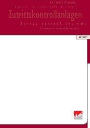
Verwendung als Teilnehmer am TS-Bus:Dieses Türcodegerät kann alternativ zum Einzelbetrieb als Teilnehmeram TS-Bus eingesetzt werden. Dazu ist neben der Funktionsumschaltungan DIP-Schalter 8 (Busbetrieb= ON) auch die Teilnehmeradresse(S1-S7) einzustellen.1 2 3 4 5 6 7 8ONOFF1 2 3 4 5 6 7 8SI 2500 mATTrafo+ -0 V DTSB12 3 4 5 6 7 8 9Busleitung "Daten"Busleitung "0 V"Die TS-Busleitung wird an den Klemmen 8 und 9 angeschlossen.Auf die richtige Polarität ist zu achten!Grundsätzlich ist die Errichter- und Bedienungsanleitung derBuszentrale zu beachten, die weitere Informationen zur Installationund Inbetriebnahme enthält.16
Montage und Installation.Achtung! Diese Hinweise zu Montage und Installationgelten nicht für Geräte mit der Typenbezeichnung<strong>421</strong>-<strong>30</strong>!17
SicherheitshinweiseDas Türcodegerät <strong>421</strong>-<strong>30</strong>-<strong>10</strong> entspricht den einschlägigeneuropäischen Normen. Bei Einhaltung der üblichen Sicherheitsregelnfür Elektrogeräte dieser Art ist ein störungsfreier unddauerhafter Betrieb gewährleistet. Einige dieser Regeln, die indiesem Zusammenhang besonders relevant sind, seien hier nocheinmal aufgeführt.Das Gerät ist vorgesehen für Aufputzmontage in Innenräumen. Esdarf nicht erhöhter Feuchtigkeit oder Nässe oder agressiverAtmosphäre ausgesetzt werden.Beim Elektroanschluß sind die einschlägigen Bestimmungen desVDE und des örtlichen EVUs zu beachten.Die Elektronik des Geräts ist gegen Störeinflüsse durchschaltungstechnische Maßnahmen und durch das Metallgehäuseweitgehend geschützt. Damit diese Maßnahmen wirksam seinkönnen sind jedoch unbedingt die "besonderen Hinweise" imAbschnitt "Elektrischer Anschluß" zu beachten.An der Elektronik des Geräts dürfen keinerlei Veränderungenvorgenommen werden.18
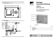
MontageZur GerätemontageDas Gerät wird üblicherweise mit vier Schrauben in der Nähe derzu sichernden Tür an der Wand befestigt. Bitte achten Sie darauf,daß keine der Schrauben Kontakt mit leitendem Material hat - etwamit der Mauerwerksbewehrung. Dies könnte unter ungünstigenUmständen zu Störeinstrahlungen führen.Abstand der Bohrungen: waagerecht:senkrecht:Schraubendurchmesser:90 mm120 mm4 mmDie Kabeleinführung kann durch jeweils drei Durchbrüche an derunteren Gehäusewand oder im Gehäuseboden erfolgen.Zur Montage des TüröffnersDer durch das Türcodegerät anzusteuernde Elektrotüröffner wirdin der üblichen Art und Weise im Schließblech und dieses imRahmen eingebaut. Die Position des Elektrotüröffners muß indiesem Fall besonders sorgfältig so auf die Schloßposition ausgerichtetwerden, daß die Schloßfalle bei geschlossener Tür mitgeringst möglichem Druck auf der Türöffnerfalle aufliegt. Da derTüröffner durch das Türcodegerät mit Gleichspannung angesteuertwird, könnte eine zu große Vorlast auf der Türöffnerfalle dieFreigabe verhindern.19
Elektrischer AnschlußBesondere HinweiseVor Entfernen der Zwischenabdeckung muß die Netzspannungabgeschaltet werden.Für alle Niederspannungsanschlüsse muß abgeschirmtesKabel verwendet werden. Die Kabelschirme sind einseitigauf die zentrale Erdanschlußklemme im Gehäuse aufzu -legen.Es dürfen nur Türöffner angeschlossen werden, die für12 Volt Gleichspannung ausgelegt sind, deren Stromaufnahmenicht über 250 mA liegt und die mit einer Freilaufdiodeausgestattet sindDer Rückmeldekontakt des Türöffners oder ein andererKontakt, der auf diesen Eingang aufgeschaltet wird, kannsowohl als Öffner als auch als Schließer aufgeschaltetwerden. Der Eingang ist flankengesteuert. Die Steuerungreagiert auf beide Schaltflanken.Bei Anschluß anderer Verbraucher als Elektrotüröffner sindgeeignete Störschutzmaßnahmen vorzusehen (zumBeispiel Freilaufdiode bei induktiven Verbrauchern).Gegebenenfalls auch die Leerlauf-Ausgangsspannungbeachten!Zur Kabeleinführung in das Gehäuse die Gummitüllen nichtentfernen, sondern kreuzförmig einschneiden und dasKabel dann stumpf hindurchschieben.20
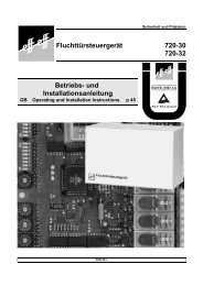
Technische DatenAnschlußspannung:Leistungsaufnahme max.:Betriebsnennspannung:max. Belastbarkeit:Leerlaufspannung:Relaiskontakt:Schaltspannung max:Schaltstrom max:2<strong>30</strong> Volt +/- <strong>10</strong>%, 50-60 Hz9,5 VA12 V - ungeregelt0,25 Aca. 22 V24 V1 ASicherungen:primär: Thermosicherung 1<strong>30</strong>°Csekundär:500 mATFreigabezeit:einstellbar 1-<strong>30</strong> sekBetriebstemperatur:0° C bis 40° CFeuchteklasse nach DIN 40040:FSchutzart nach DIN EN 60529 2000-09: IP <strong>30</strong>Gehäuse:Material:Farbton:Abmessungen (B x H x T):Alu-Druckguß pulverbeschichtetRAL 9002 grauweis120mm x 145mm x 57mmNormkonformität:Seite 22:Anschlußplan21
Drehschalter fürTürentriegelungszeit(keine Funktion beiBusbetrieb)Programmiertaste(keine Funktion beiBusbetrieb)Ausgangsspannungfür dasVerriegelungselement12 V- Türöffner-+ - Relais1GrundplatineSchaltspannungmax. 24 V DCSchaltstrommax. 1 ATöTüTSB0V DBus2 3 4 5 6 7 8 9Sicherung F2500 mATTrafo2<strong>30</strong> V ACL1 NCodierschalter:Für Standardbetrieb alleSchalter in Stellung OFF.Für den Busbetrieb Schalter8 in Stellung ON.Schalter 1-7 dient zur Einstellungder Teilnehmeradresse.Zentrale ErdanschlußklemmeimGehäuseKabelschirme und Schutzleiterauflegen !Auf richtige Polaritätachten !TüröffnertasterexternAnschlußRuhestromtüröffner12 V- Türöffner-+ - RelaisTöTü1 2 3 4 5 6 7blaurotgraublaurotgraugrüngelb- +grüngelbL1 N PEArbeitsstrom-Türöffner 1405/1405 RRAuf richtige Polaritätachten !- +Ruhestrom-Türöffner 3405/3405 RRTastaturplatineISchiebeschalter:Für die Freigabe der Funktion Dauerentriegelungdurch den Hauptcode, muß derSchalter in Stellung II stehen!II22D00116-A0000<strong>10</strong>2
Tür Nr.: BeschreibungCodeart: Hauptcode Benutzercode 1 Benutzercode 2 Benutzercode 3Code:ausgegeben an:(Name)am:(Datum)Gelöscht am:(Datum)23
effeff Fritz Fuss GmbH & CoKommanditgesellschaft auf AktienBildstockstraße 2072458 Albstadt / DeutschlandTel: (07431) 123-0Fax: (07431) 123-240/<strong>30</strong>3An Assa Abloy Group companywww.effeff.cominfo@effeff.comASSA ABLOY
RSECURITY AND PRECISIONDoor Code Unit <strong>421</strong>-<strong>30</strong>-<strong>10</strong>Operating and Installation Instructions957532-756382-143269-736-61954-7<strong>30</strong>276-756493-2645-1840-7563-01-576-<strong>30</strong>28-2555-6983-8673-427-6-65-86-73650-600251-7501- 32-5-7392-984-286-8<strong>30</strong>27-5431-85648-3-578- 749-9012-<strong>10</strong>007-84729-7-465-723935-3476- 243-05846-<strong>10</strong>4-59-7364-239538-73942-827- 341--43331-46573-746296-64-7264-6-45372- 6354-14325-243-19-63525--4657-8712-724- 769-7382-9898-8-0012-921387-811175-812- 128-736-2-87989-999111-82591-6574-3119--615243-859476-918273-56871-954--223884- 2857-7465-38-36-78925--045324-6819-4567-32-57312-984--286-8<strong>30</strong>27-5431-856483-576- 749--9012-<strong>10</strong>007-84729-7465-723935--3476-15-205 2431-05846-<strong>10</strong>4559-73645-239538-739428 34-43331-46-573-746296-647-7264-645372- 6-354-14325-24344-19-63525-4657--878237-747<strong>421</strong>-3498-279554-123-9737-3332- 957532-756382-143269-736-61954-7<strong>30</strong>276-756493-2645--1840-756<strong>30</strong>1-576-<strong>30</strong>28-2555-6983--8673-4276-65-86-73650-600251--32-57392-984-286-8<strong>30</strong>27-5-7501-431-856483-578- 749-9012-<strong>10</strong>007--84729-7465-723935-3476- 243-05-846-<strong>10</strong>459-7364-239538-73942-8D0011605
Dear Customer,The effeff door code unit <strong>421</strong>-<strong>30</strong>-<strong>10</strong> satisfies modern securityand organization requirements. It is produced by the most moderntechnical production methods of high-quality materials andcomponents. Its service life is usually much longer than theguarantee period granted by effeff provided that some fundamentalrules and regulations are observed:Do not modify the door code unit in any way!Avoid moisture penetrating the door code unit! The door codeunit must not be used for outdoor installations. It may only becleaned using a moist cloth. Do not use any solvents!Installation and connection must be carried out by a qualifiedtechnician! ( Installation of the door release by a joiner or alocksmith, electrical connection by an electrician.)Failure to observe these instructions or our general terms ofwarranty will invalidate the guarantee.Please read the following instructions on the function and handlingof the door code unit carefully. Only if you understand how itoperates and which possibilities it offers, you will be able to use it toyour satisfaction.
ContentsConcise Programming Instructions 28Operating Instructions 29Function and Operation <strong>30</strong>General Function <strong>30</strong>Programmable Codes <strong>30</strong>Permanent Unlocking <strong>30</strong>Connection to Other Elements 31Timing 31Error Code Evaluation 31Operation and Indication 32Programming 33Programming the Master Code 33Programming the User Codes 34Deleting a User Code 35Termination of Programming 35Special Cases 36Three Programming Rules 37Locking System 38Application as TS-BUS system participant 40Mounting and Installation 41Safety Specifications 42Installation 43Installation of the Door Code Unit 43Installation of the Door Release 43Electrical Connection 44Special Information 44Technical Data 45Connection Diagram 46These operating instructions are subject to the laws on the protection of copyright. Copright1996 by effeff
Concise ProgrammingInstructionsMaster Code1.Press programming button on main board2.Enter new code3.Press key+User Code1.Press programming button on main board2.Press key+3.Enter index , or1 2 34.Press key+5.Enter new code6.Press key+28
Operating InstructionsAttention! These operating instructions do not applyto door code unit <strong>421</strong>-<strong>30</strong>!The following descriptions of the funktion and the programminginstructions are only valid when the device is used in stand alonefunktion.If it is used as a participant of the TS-bus, its funktions dependon the programming of the central bus controll unit.29
Function and OperationGeneral FunctionThe door code unit is used to restrict access to specific rooms toauthorized persons. Unlocking of the door depends on a freelyprogrammable numerical code consisting of up to six digits. Whenthe programmed code number is entered via the keypad of the doorcode unit, the electric door release is unlocked for a selectableperiod and the door can be opened. After expiry of the door releasetime the door release is relocked. Subsequently the closed door islocked again.Programmable CodesThe door code unit can store up to four different codes at the sametime. Three of these codes, the ”user codes”, can be deleted at anymoment, whereas the “master code” can only be changed. Only themaster code is authorized to activate or deactivate permanentunlocking. Each code is a number between 00 and 999999 and canbe selected at will. That means that 1.111.<strong>10</strong>0 different codes arepossible. (Please observe the restrictions explained in theprogramming instructions.)Permanent UnlockingPermanent unlocking can be activated by means of the mastercode. For this purpose the key + is pressed before entering thecode. The relay contact remains activated, until the master code isentered again after pressing the key - . This function can beswitched off by moving the sliding switch at the back of the keypadboard into position I.Attention!The permanent unlocking funktion must be activated by the slidingswitch on the backside of the keypad board. The funktion is activ,when the switch is in position II.<strong>30</strong>
Connection to Other ElementsThe door code unit controls an appropriate standard electric doorrelease (12 V DC, maximum 250 mA current consumption). As theoutput contact of the door code unit is a potential-free changeovercontact, other elements can be controlled as well. However, it isessential to observe the technical data indicated in the installationinstructions (see page 41 and following).TimingThe door open time can be set at the door code unit between oneand thirty seconds, by means of the rotary switch located beside theprogramming button. The period can be set in graduations of twoseconds. In case of switch position “0" the relay reaction period isone second.To avoid tailgate problems if door releases with monitoring areused, timing is automatically canceled when the monitor contact isactivated. This means that the subsequently closed door is lockedand a person who wants to open the door immediately afterwardsmust enter the code again.Error Code EvaluationAttempts to find the correct code by trying out are ineffective. If nocorrect code has been entered after actuation of a certain number ofkeys, the keypad is locked for <strong>30</strong> seconds.This status cannot be recognized externally and cannot be resetwithout opening the door code unit.The number of incorrect entries which is allowed depends on theprogrammed codes. It is double the number of digits the longestprogrammed code comprises plus one. If for example a 6-digitmaster code is programmed, a valid code must have been enteredafter actuation of the thirteenth key at the latest. Otherwise thekeypad is locked.31
Operation and IndicationOperation of the unit is simple and does not require any special instructionof the users. The code can be entered directly. When thecode is entered, the output contact is activated and the door can beopened. This is signaled by a green LED which remains lit as longas the door release is activated.32
ProgrammingProgramming is also very simple. The unit is opened by means ofthe key and switched into the programming mode by brief operationof the programming button (on the main board on top left). Theprogramming status can be recognized by the flashing green LED atthe front.If, after having entered at least two numbers, for four seconds nofurther key is actuated, the programming mode is switched offautomatically, the new code is programmed.Programming the Master CodeExample 1: The number 659874 has to be programmed as newmaster code.Key actuationsNotesThe door code unit is opened bymeans of the key.The programming mode is switchedon by pressing theprogramming button on the mainboard.685794The new master code is enteredvia the keypad. As the maximumnumber of digits has beenentered, the code is programmedand the programming mode isswitched off automatically.The master code will cover the necessary functions in most applications.The master code, like all other codes, can comprise up tosix digits and consist of freely selectable numbers. It can bechanged by switching on the programming mode and entering thenew master code via the keypad.33
Programming the User CodesFor special applications three additional user codes can beprogrammed. These codes cannot activate permanent unlockingand can be deleted at any moment by a simple operation. Theymust be given a special index, i.e. the number “1", “2" or “3", inorder to be able to refer to each code individually whenprogramming or deleting. When programming a user code thisindex – between two actuations of the key + – must precede thenew code. Therefore programming will be effected as follows:Example 2: The number 4521 has to be programmed as seconduser code.Key actuationsNotesThe door code unit is opened bymeans of the key.The programming mode is switchedon by pressing the programmingbutton on the mainboard.+This key is pressed before determinationof the index.2The number 2 is entered asindex of the new user code.+ This key is pressed after determinationof the index.34
4 521The code is entered.+Confirmation and switching offthe programming mode.Deleting a User CodeAn existing user code is deleted by switching on the programmingmode and pressing the key - after entering the index of therespective code.Termination of ProgrammingA programming procedure can be terminated in different ways.Under certain conditions the door code unit changes automaticallyfrom the programming mode into the normal mode:A) If the programming mode is switched on and no key on thekeypad is pressed for fifteen seconds, the programming mode isswitched off automatically and the existing code remains valid.B) If, after having entered at least two numbers in the programmingmode, no other key is pressed for four seconds, the programmingmode is switched off automatically and the new code isprogrammed.C) After all numbers of a new code have been entered, the key +may be pressed. In this way the new code is programmed and theprogramming mode is switched off.35
D) Programming can be interrupted by pressing the key (forexample after an incorrect entry). The numbers which have beenentered before are not stored and the existing code remains valid.In this way the programming mode is switched off and must beactivated again, if required.E) If the maximum number of digits (six digits) of a new code hasbeen entered, the code is programmed and the programming modeis automatically switched off.-Special CasesAs up to four codes can be programmed, the following restrictionsmust be observed:A) As soon as a valid code has been entered, it is recognized by thedoor code unit. Therefore a short code should not correspond withthe beginning of a long code. Example: The master code is 123890and a user code is 123. When the master code is entered, the doorcode unit recognizes the user code after the third digit and the dooris unlocked.B) If in the above example the short code has been programmed asmaster code, this results in the fact that the user code is authorizedto activate permanent unlocking, as the system recognizes the firstthree digits of the user code as master code.36
Three Programming RulesWhen programming please observe the following three rules inorder to avoid problems or irritations, which may be caused byoverlapping or discrepancies.I.) Write down the existing codes and keep this note in a safeplace. So you can inform yourself before programming. 2II.) Delete user codes which are no longer required.III.) When programming several codes make sure that a shortcode does not correspond with the beginning of a long code.2We recommend to use the form on page 47 in the appendix(It may be enlarged when copying.)37
Locking SystemAs the door code unit <strong>421</strong>-<strong>30</strong>-<strong>10</strong> can store up to four differentcodes, a system similar to a locking system with up to four levelscan be established by using several door code units.In the following example nine doors have to be controlled in anorganization structure which comprises the general manager, twodivision managers, four department managers and eight employees.Nobody should be forced to remember more than one code.This organization structure is shown in the following table. Ofcourse the possibilities of such a system are limited and only withrestrictions comparable with the possibilities of a locking systemwhich can be established by means of modern lock cylinders.However, in comparison with a genuine locking system, this systemoffers the advantage that no cylinder has to be exchanged when astaff member leaves. Only the respective code has to be changedand no other person is concerned by this change of code.In this example the codes A, B, E and K are programmed on door4, code A is programmed on door 5 and the codes A, C, G and Oare programmed on door 9. Each person must remember only onecode.38
master codeA(general manager)divisioncode 1B(divisionmanager)divisioncode 2C(divisionmanager)departmentcode 1D(departmentmanager)departmentcode 2E(departmentmanager)departmentcode 3F(departmentmanager)departmentcode 4G(departmentmanager)code 1(employee 1)Hcode 2(employee 2)Icode 3(employee 3)Jcode 4(employee 4)Kcode 6(employee 6)Lcode 7(employee 7)Mcode 8(employee 8)Ncode 9(employee 9)Odoor 1ABDHdoor 2ABDIdoor 3ABEJdoor 4ABEKdoor 5Adoor 6ACFLdoor 7ACFMdoor 8ACGNdoor 9ACGO39
Application as TS-BUS system participant.Alternatively to an individual operation this code access systemcan be used as TS BUS system participant.Therefore the functions must be changed at DIP switch 8 (BUSoperation= ON) and the address of the participant (S1-S7) mustbe set.1 2 3 4 5 6 7 8ONOFF1 2 3 4 5 6 7 8F 2500 mATTrafo+ -0 V DTSB12 3 4 5 6 7 8 9BUS lead "Data"BUS lead "0V"The TS BUS lead has to be connected to binder 8 and 9.Please note that the correct polarity is mandatory.Kindly observe the operating instructions of the BUS control panelwhich contains further details on the installation and initiation.40
Mounting and InstallationAttention! This information on mounting and installationdoes not apply to code unit<strong>421</strong>-<strong>30</strong>!41
Safety SpecificationsThe door code unit <strong>421</strong>-<strong>30</strong>-<strong>10</strong> complies with the relevant Europeanstandards. The usual safety regulations concerning electricalappliances must be observed to assure permanent function withoutproblems. Some of these regulations which are especially importantin this connection are indicated below.The unit has been designed for surface mounting in indoorinstallations. It must not be exposed to moisture, water or aggressivesubstances.The electrical connection must comply with the rules andregulations applicable in the country of use.The electronics of the door code unit is largely protected againstnoise influences by proofing measures and by the metal housing.Please observe the “Special Information” in the paragraph“Electrical Connection”, so that these measures will be effective.Do not modify the electronics of the door code unit!42
InstallationInstallation of the Door Code UnitThe door code unit is installed near the door to be controlled bymeans of four screws. The screws must not come into contact withconductive material as this could result in noise influences.Distance of the borings: horizontal:vertical:Screw diameter:90 mm120 mm4 mmThe cable is introduced through three apertures in the base of thehousing.Installation of the Door ReleaseThe electric door release which is controlled by the door code unitis installed in the faceplate in the frame as usual. The position of thedoor release must be adjusted very carefully to the lock position, sothat the latch does not pressure on the keep. As the door release iscontrolled by the door code unit by means of direct current,unlocking could be prevented if the initial load on the keep is toohigh.43
Electrical ConnectionSpecial InformationBefore removing the intermediate cover the mains voltagemust be switched off.Only screened cable may be used for all low voltage connections.All screening has to be connected to the centralearth terminal inside the housing.Only door releases which have been designed for operationby 12 V DC may be used. They must have a current consumptionof less than 250 mA and be equipped with a sparksuppression diode.The monitor contact of the door release or another contactwhich is connected to this input may be normally closed ornormally open.If other power consumers are connected, adequate proofingmeasures must be taken ( e.g. spark suppression diode incase of inductive power consumers). Please observe theno-load output voltage!Do not remove the rubber bushing when introducing thecable into the housing, but cut it in cross-shapedly and introducethe cable bluntly.44
Technical DataConnecting voltage:Maximum power consumption:Rated operating voltage:Maximum load capacity:No-load voltage:Relay contact:Maximum switching voltage:Maximum switching current:2<strong>30</strong> V +/- <strong>10</strong> %, 50 - 60 Hz9,5 VA12 V - unregulated0,25 Aapprox. 22 V24 V1 AFuses:Primary: Thermal fuse 1<strong>30</strong>°CSecondary:Tr 5 500 mATRelease period:selectable between 1-<strong>30</strong> sec.Operating temperature:0 C to 40 CHumidity rating according to DIN 40040:FProtection rating according to DIN EN 60529 2000-09: IP <strong>30</strong>Housing:Material:Colour:Dimensions (WxHxD):Standard:aluminium die-casting,powder-coatedRAL 9002 grey white20 mm x 145 mm x 57 mmCEPage 46:Connection diagram45
main boardrotary switch fordoor release period(no funktion in combinationwith the TS-Bus )programming button(no funktion in combinationwith the TS-Bus )output voltage forlocking elementswitching voltagemax. 24V DCswitching currentmax. 1AFuse F 2500 mATtransformerCode switch:For standard use all switchesmust be in position OFF.In combination with the TS-Busswitch 8 must be in position ON.The switches 1-7 are used forsetting the participator adress .12 V-+ -door releaserelayTSB0V Dbus2<strong>30</strong> V ACL1 N12 3 4 5 6 7 8 9earth terminal in the housing -connect shield and earth leadPay attention to thecorrect polarity!blueredgrey- +12 V-+ -1 2 3 4 5 6 7blueredgreygreenyellowgreenyellowexternal door releasepush-buttonL1 N PEfail locked door release 1405/1405 RRConnection of fail-unlockeddoor releasedoor releaserelayPay attention to thecorrect polarity- +fail-unlocked door release 3405/3405 RRkeypad boardIsliding switch:For permanent unlocking by means ofmaster code the sliding switch must bein position II.II46D00116-A0000202
door no.: descriptiontype of code: master code user code 1 user code 2 user code 3code:given to:(name)on:(date)deleted on:(date)47
effeff Fritz Fuss GmbH & CoKommanditgesellschaft auf AktienBildstockstraße 2072458 Albstadt / DeutschlandTel: (07431) 123-0Fax: (07431) 123-240/<strong>30</strong>3An Assa Abloy Group companywww.effeff.cominfo@effeff.comASSA ABLOY