NEWS02-02 - SOCON Sonar Control Kavernenvermessung GmbH
NEWS02-02 - SOCON Sonar Control Kavernenvermessung GmbH
NEWS02-02 - SOCON Sonar Control Kavernenvermessung GmbH
- Keine Tags gefunden...

Erfolgreiche ePaper selbst erstellen
Machen Sie aus Ihren PDF Publikationen ein blätterbares Flipbook mit unserer einzigartigen Google optimierten e-Paper Software.
Seite 22Forschung & Entwicklung / Research & Development Page 22CavBase - Relationale Datenbanksystemefür KavernenanlagenBei den CavBase-Produkten handelt es sich um RelationaleDatenbanksysteme, die als klassische Client-Server-Anwendungen entwickelt wurden und derenBetrieb sowohl über Intra- als auch über Internet möglichist. Mit diesen Systemen können die bei Kavernenanlagentäglich anfallenden Betriebsdaten dezentralerfasst, verwaltet sowie die erforderlichen Berechnungenund Analysen durchgeführt werden. Zur Ausgabeder Daten und Berichte ist ein frei konfigurierbarerReportgenerator integriert worden.Eine hohe Leistungsfähigkeit und der betriebliche Nutzender einzelnen CavBase-Produkte wurden durchdie Kooperation mit einem in dem jeweiligen Sektorerfahrenen Unternehmen sichergestellt..CavBase - relational databasesystems for cavern fieldsCavBase products are relational database systemswhich were developed as classic client-server applicationsand which can be operated not only within anIntranet but also through the Internet. These systemscan save at decentralized locations all the daily operatingdata of cavern fields and subsequently managethese data and perform the necessary calculationsand analyses. A freely configurable report generator isintegrated for outputting the data and reports. Our cooperationwith a company experienced in each sectorguarantees high performance and the operationalbenefits of the individual CavBase products.Gemeinsam mit der Firma DEEP. Underground Engineering<strong>GmbH</strong> wurde das erste CavBase-Datenbanksystem für den Bau und Betrieb von Solegewinnungskavernenentwickelt. Es trägt die BezeichnungCavBase Production und hat bereits Einzug indie betriebliche Praxis gehalten.(siehe Bericht Seite 23)Mit dem System CavBase Gas-Storage befindet sichzur Zeit das zweite CavBase-System in Entwicklung,das speziell für den Betrieb von Gaskavernenfeldernkonzipiert wurde. Mit diesem System können insbesonderedie zur Betriebsführung erforderlichen gebirgsmechanischenund thermodynamischen Berechnungendurchgeführt werden.(siehe Bericht Seite 25)Als drittes Produkt soll mit CavBase Oil-Storage einentsprechendes Datenbanksystem für Ölspeicherkavernenerstellt werden. Dieses Datenbanksystem befindetsich derzeit noch in der Konzeptionsphase.The first CavBase database system for constructingand operating brine production caverns was jointly developedwith DEEP Underground Engineering <strong>GmbH</strong>.It is called CavBase Production and has alreadybeen used in cavern operations.(read report on page 23)Under development is the second CavBase system,CavBase Gas-Storage, which is designed speciallyfor the operation of gas cavern fields. This system isaimed particularly at carrying out the rock mechanicsand thermodynamic calculations necessary for runningthe operations.(read report on page 25)A third database system, CavBase Oil-Storage, is tobe set up similarly for oil storage caverns. This systemis currently still in the design phase.Dr. A. ReitzeDr. A. Reitze
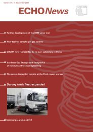
Seite 23Forschung & Entwicklung / Research & Development Page 23CavBase – ProductionEinführung bei Akzo Nobel Salz <strong>GmbH</strong>Für die Einführung von CavBase bei Akzo an ihrenStandorten Stade-Süd und Hollenbeck wurde das Projektin sechs Phasen gegliedert:• Infrastruktur der Standorte Stade–Süd und Hollenbeckermitteln.• Aktuelles Datenmanagement–System analysieren.• Aktuelles Berichts- und Informationssystem analysieren.• Definition und Festlegung der Anforderungen an dasCavBase-System.• Integration von Akzo-Daten und aller weiteren Anforderungenseitens Akzo.• Implementierung, Schulung und Datenbetrieb.CavBase – ProductionIntroduction of CavBase at Akzo Nobel Salz <strong>GmbH</strong>The project of introducing CavBase at the Akzo locationsof Stade–Süd and Hollenbeck was divided intosix phases:• Determination of cavern field structure at the locationsof Stade–Süd and Hollenbeck.• Analysis of existing data management system.• Analysis of existing reporting and information system.• Definition and fixing of the demands on theCavBase system.• Integration of Akzo data as well as all the otherAkzo requirements.• Implementation, training and using the data.Infrastruktur der Standorte Stade-Süd und Hollenbeckermitteln:Anhand von R & I – Plänen wurde die Anlagenstrukturvon Stade–Süd und Hollenbeck ermittelt. Hierbei kames insbesondere darauf an zu erkennen, in welchemtechnischen Zusammenhang die einzelnen Kavernenzueinander stehen. Unter anderem mussten folgendeFragen geklärt werden: Wo werden welche Messwerteerfasst? Geschieht dieser Vorgang automatisch oderwerden die anfallenden Daten vom Betriebspersonalper Hand erfasst? Können die einzelnen Kavernen miteinandergekoppelt werden? Nach Ermittlung dieserInformation ist man in der Lage, die Anlagenstrukturenin CavBase abzubilden.Aktuelles Datenmanagement–System analysieren:In der zweiten Phase ging es darum zu beschreiben,welche Daten z.Z. verwaltet werden, ob analoge und /oder digitale Daten existierten und in welchen Formatendiese vorliegen.Nach Abschluss dieser Analyse konnten alle z.Z. auftretendenDaten entsprechend ihrer Themen der Cav-Base Datenbank zugeordnet werden und gleichzeitigwurde eine Grundlage für eventuelle Erweiterungen desCavBase–Systems geschaffen. →Determination of cavern field structure at locationsof Stade–Süd and Hollenbeck:The cavern field structure of Stade–Süd and Hollenbeckwas determined using R & I plans. In this respectit was of primary significance to recognize the technicalrelationship that exists between the individual caverns.The following questions, amongst others, had tobe answered: where will what survey values be measured?Will this procedure be automatic or will any accrueddata have to be acquired manually by the staff?Can the individual caverns be connected with one another?After finding out this information will we be in aposition to depict the field structures in CavBase?Analysis of existing data management system:The second phase was concerned with describingwhat data were currently managed, whether analogand/or digital data exist and in what formats thesedata were available. After this analysis had been concludedall the data that were currently available couldbe thematically assigned to the CavBase databaseand at the same time a basis for the possible extensionof the CavBase system was set up. →
Seite 24Forschung & Entwicklung / Research & DevelopmentPage 24Aktuelles Berichts- und Informationssystem analysieren:Sämtliche Berichte, Protokolle etc. wurden gesichtetund nach verschiedenen Kriterien untersucht. Zumeinen ging es darum, die z.Z. gebräuchlichen Auswertungennach Messdaten und berechneten Daten zutrennen, um eine Berechnungsgrundlage für die zukünftigvon CavBase zu erstellenden Reports undGraphen zu erstellen. Außerdem dienen diese Informationendazu, die verwendeten Berechnungsroutinenggf. zu optimieren oder alternative Berechnungsmöglichkeitenvorzustellen.Definition und Festlegung der Anforderungen andas CavBase-System:In der Phase 4 wurden zwischen Akzo und DEEP. gemeinsamdie Anforderungen und das Pflichtenheft vonCavBase festgelegt. Insbesondere wurde Wert daraufgelegt, dass die bisherigen Berichte, Protokolle undReports auch im neuen System erstellt werden können.Integration von Akzo-Daten und aller weiterenAnforderungen seitens Akzo:In der Phase 5 wurden Verfahren entwickelt, um allein Frage kommenden Daten der letzen zwei Betriebsjahremöglichst automatisch in die CavBase-Datenbankzu übernehmen. Des weiteren wurden alle Reportsund Graphen erstellt und mit dem vom Kundengewünschten Layout versehen. Zusätzlich wurde eineEingabemaske entwickelt, welche in ihrem Aufbau denbisherigen Datenerfassungsformularen gleicht. DieseEingabemaske reduziert die Anlernphase des Betriebspersonalsauf ein Minimum.Implementierung, Schulung und Datenbetrieb:Die Implementierung der Software vor Ort benötigte 3Tage bei laufendem Betrieb. Parallel dazu wurde dasPersonal entsprechend geschult und eingewiesen.Danach schloss sich eine zweiwöchige Testphase an.BetriebserfahrungDas als Pilotprojekt für Akzo dienende CavBase-System in Stade wurde voll im Zeit- und Kostenrahmenund zur großen Zufriedenheit des Kunden erstellt.Das Management entschied daraufhin CavBasefür alle Solegewinnungsbetriebe einzusetzen. DasProjekt Delfzijl / Niederlande befindet sich zur Zeit inder Konzeptionsphase.Analysis of existing reporting and information system:All existing reports, listings and so on were looked atand evaluated based on various criteria. One aim wasto separate the current usual interpretations based onsurveyed data and calculated data in order to set up acalculation basis for the reports and graphs to be preparedin the future by CavBase. In addition this informationprovides a way of possibly optimizing the calculationroutines used or presenting alternative meansof calculation.Definition and fixing of the demands on theCavBase system:In phase 4 Akzo and DEEP. jointly worked out whatwas required of CavBase and the CavBase list ofspecifications. It was seen as particularly importantthat the type of reports and listings made previouslycould also be prepared in the new system.Integration of Akzo data as well as all the otherAkzo requirements:In phase 5 techniques were developed of transferringto the CavBase database, as far as possible automatically,all the pertinent data of the last two years of operation.Moreover all reports and graphs were preparedwith the layout required by the client. An inputwindow was also created that had a similar layout tothe previous data acquisition forms. Use of this windowreduced to a minimum the learning time of theoperating staff.Implementation, training and using the data:Implementation of the software on site was made duringnormal operations and took three days. At thesame time the staff were appropriately instructed andtrained. A two-week test phase was subsequently carriedout.Concluding experienceThe CavBase system in Stade, which served as a pilotproject for Akzo, was set up fully within the time andcost framework and to the complete satisfaction of theclient. Following this success, the management decidedto use CavBase for all its brine production operations.The Delfzijl / Netherlands project is presentlyin the conceptual phase.O. RecklerO. Reckler
Seite 25Forschung & Entwicklung / Research & DevelopmentPage 25Entwicklung vonCavBase Gas StorageZur Zeit arbeiten die Pipeline Engineering <strong>GmbH</strong>, Essen,(PLE) und die <strong>SOCON</strong> an der Entwicklung vonCavBase Gas Storage. Voraussichtlich im zweitenQuartal 2003 steht dann neben CavBase Productionein zweites Anwendungsmodul von CavBase zur Verfügung.CavBase Gas Storage wird dem Kavernenbetreiberim Rahmen seiner Betriebsführung die Möglichkeitgeben, sowohl gebirgsmechanische als auchthermodynamische Berechnungen durchzuführen.Development ofCavBase Gas StoragePipeline Engineering <strong>GmbH</strong>, Essen, (PLE) and SO-CON are currently developing CavBase Gas Storage.This second application module of CavBase will beavailable alongside CavBase Production provisionallyas of the second quarter 2003. CavBase Gas Storagewill provide cavern operators as part of their routineoperations with the opportunity of carrying out not onlyrock mechanics calculations but also thermodynamiccalculations.Das thermodynamische Modul beinhaltetdie folgenden Anwendungsmöglichkeiten:• Statische Druckberechnungen vom Kavernenkopfbis zum –sumpf und umgekehrt• Gasmengenberechnungen (isothermes Arbeits-, Kissen-und Gesamtgas)• Dynamische Druck- und Temperaturberechnungen(History Match) vom Kavernenkopf bis zum –sumpfund umgekehrt in Abhängigkeit der Volumenrate.Falls keine Einzelvolumenraten zur Verfügung stehen,werden die Kopfdruckdaten zu einer einfachenRatenabschätzung herangezogen. Das Programmerrechnet dann iterativ die exakte Volumenrate.• Dynamische Druck- und Temperaturberechnungenvom Kavernenkopf bis zumSumpf und umgekehrt in Abhängigkeitder vorgegebenen Volumenrate(Leistungsvorhersage).• Prognoserechnungen mit beliebigemFüllstand,• Berücksichtigung von GrenzundAbbruchkriterien,• Gasmengenberechnungen(polytropes Arbeits-, Kissen- undGesamtgas),• Hydratbildungsbedingungen(optional),• Spätester Zeitpunkt der Wiederbefüllungdes Gesamtspeichers,• Leistungsvorhersage Gesamtspeicher.5 K HB= ? A L A HO E C B H = JE H ? I = JB H = JE 2 9 DJ ? = 6 9 DJ ? = 2 3 J6 3 J2 E6 EThe thermodynamic module encompassesthe following application options:• Static pressure calculations from the cavern head tothe sump bottom of the cavern and vice versa• Gas quantity calculations (isothermal working, pillowand total gas)• Dynamic pressure and temperature calculations(history match) from the cavern head to the fluid poolat the bottom of the cavern and vice versa in relationto the volume rate. If no individual volume rates areavailable, the head pressure data are used to makea simplified estimate of the rates. The program thencalculates the exact volume rate iteratively.• Dynamic pressure and temperature calculations from2 H @ K ? JE 2 = EJ6 = EB @61 A ? JE = EJ3 @ @ 2@ 6F HA I I K HA = @JA F A H= JK HA I I A I E JD A F H @ K ? JE I JHE C6 ? = I 2 ? = I 0 A = JA N ? D = C A1 EJE= E = JE B? @ A Ithe cavern head to the sump bottomof the cavern and vice versain relation to the given volumerate (predicted performance).• Calculated predictions usingvarious gas inventories,• Consideration of boundary andstop criteria,• Gas quantity calculations(polytropic working, pillow andtotal gas),• Hydrate formation conditions(optional),• Latest time/date for refilling entirestorage cavern,• Predicted performance for overall storage cavern.In allen Programmen basieren die Berechnungen derRealgasfaktoren auf dem in der ISO 12213/2 beschriebenenVerfahren AGA8DC 92. →Calculations of the real gas factors are based in allprograms on the AGA8DC 92 technique described inISO 12213/2. →
Seite 26 Forschung & Entwicklung / Research & Development Page 26Das gebirgsmechanische Modul beinhaltetdie folgenden Anwendungsmöglichkeiten:• Berechnung der Tages- und kumulativen Konvergenzmit einem empirischen Konvergenzmodell.• Konvergenzprognose und History Match auf der Basisdes vom thermodynamischen Modul berechneten Kavernendrucks.Alle Berechnungsmodule sind in zahlreichen Feldversuchengetestet worden und lassen sich problemlos durchKalibrierung auf neue Speicherlokationen übertragen.Die neue Software wird im Erscheinungsbild und derBedienung den CavInfo-Programmen entsprechen undsich durch sehr kurze Rechenzeiten auszeichnen.Dr. M. KrieterThe rock mechanics module encompassesthe following application options:• Calculation of the daily and cumulative convergenceby means of an empirical convergence model.• Convergence prediction and history match based onthe cavern pressure calculated from the thermal dynamicmodule.All the calculation modules have been checked in numerousfield tests and can be easily applied to newstorage locations after recalibration.The appearance and use of the user interface of thenew software will be similar to those of other CavInfoprograms, and the software itself will be characterizedby very short processing times.Dr. M. Krieter(Am 22. November 20<strong>02</strong> wird CavBase Gas-Storage dasThema eines <strong>SOCON</strong>-Seminars sein.Es sind noch Plätze frei!)(CavBase Gas-Storage will be the topic of a <strong>SOCON</strong> seminarto be held on 22 November 20<strong>02</strong>.Seats are still available.)CavInfo Software Suite<strong>SOCON</strong> bietet interessierten Kunden seit einigen Jahrendas Windows-basierende Softwarepaket CavInfoan. Eine Software ist jedoch nur so gut wie ihre ständigePflege und Weiterentwicklung. In den nachfolgendenBeiträgen möchten wir Sie deshalb über den aktuellenStand sowie über verbesserte und neue Funktioneneinzelner Programme der CavInfo Software Suite informieren.Die CavInfo Software Suite beinhaltet die ProgrammeCavView, CavLog, CavMap, CavWalk und CavMovie.Systemanforderung: IBM-kompatibler PC, min. 16MBRAM, WIN95 und höher(Preise auf Anfrage)CavInfo software suiteFor several years now <strong>SOCON</strong> has been offering interestedclients the Windows-based CavInfo softwarepackage. Of course, software is only as good as itscontinuous updates and further development. Thereforein the following articles we want to inform readers of thecurrent situation as well as of improved and new functionsin the individual programs of the CavInfo SoftwareSuite, which is made up of the programs CavView,CavLog, CavMap, CavWalk and CavMovie.System requirements: IBM compatible PC, min. 16MBRAM, WIN95 or higher(prices on request)Die Softwareentwickler:The software developers:v.Links / from leftA. Stille, M. Külshammer, Dr. Z. Ma
Seite 27 Forschung & Entwicklung / Research & Development Page 27CavView - Darstellung und Analyse von<strong>Kavernenvermessung</strong>enCavView ist ein Programm, das dem Anwender ermöglicht,die von <strong>SOCON</strong> ausgelieferte Kunden-Datei einer<strong>Kavernenvermessung</strong> einzulesen und u.a. in Form vonHorizontal-/Vertikalschnitten, Volumen-, Radien- oder3D-Ansichten zu betrachten und zu analysieren.CavView - display and analysis ofcavern surveysCavView is a program that allows the user to read inthe customer file of a cavern survey supplied by<strong>SOCON</strong> and to analyze and view the data, for instanceas horizontal/vertical sections, as volume or radius displaysor as 3D views.Abbildung:von links nach rechtsHorizontalschnittdarstellungVolumendarstellungRadiendarstellungVertikalschnittdarstellungPerspektivansichtRadienabwicklungFigure:from left to rightHorizontal sectionVolume displayRadius displayVertical sectionPerspective viewUnrolled radiiAuszug der in CavView enthaltenden Funktionen:• Horizontal- und Vertikalschnitte,• Perspektivische Ansicht,• Volumendarstellung und –tabelle,• Radiendarstellung (minimaler, mittlerer, maximalerRadius und Durchmesser), Radienabwicklung sowieRadiendifferenzen,• Einblendung der größten Ausdehnungen, Schwerpunktesowie Hinter-/ Untersolungen in den Horizontalschnitten,• Darstellung des Messberichtes,• Vergleich mehrerer Messungen,• Überblick über alle Horizontal-/Vertikalschnitte inForm eines Kurzberichtes,• Messfunktionen, Grafik-Editor, Text- und Grafik-Export,• Skalierte Ausdrucke mit wählbaren Maßstäben,• Ausgabe von sämtlichen Tabellen im ASCII-Format.Some of the functions provided by CavView:• Horizontal and vertical sections,• Perspective view,• Volume display and table,• Radius display (minimum, average, maximum radiusand diameter), unrolled radii as well as radiusdifferences,• Indication of the greatest extensions, centers ofgravity as well as of hidden leached pockets in thehorizontal sections,• Display of the survey report,• Comparison of several surveys,• Overview of all horizontal/vertical sections in theform of a short report,• Measuring functions, graphics editor, text andgraphics export,• Scaled printouts at selected scale,• Output of all tables in ASCII format.M. KülshammerM. Külshammer
Seite 28 Forschung & Entwicklung / Research & Development Page 28CavLog - Darstellung und mathematischeBearbeitung von Log-DatenDas Programm CavLog ermöglicht dem Anwender von<strong>SOCON</strong> gemessene LOG-Daten auf vielfältige Art undWeise darzustellen und darüber hinaus mathematischeNeuberechnungen der Logs durchzuführen.CavLog - Display and mathematicalprocessing of log dataThe CavLog program provides the user with a tool fordisplaying in a variety of ways log data measured by<strong>SOCON</strong> and moreover allows him to mathematicallyrecalculate the logs.(Fortsetzung auf Seite 29)(continued on page 29)Auszug der in CavLog enthaltenden Funktionen:• LOGs können in beliebiger Reihenfolge zusamengestelltwerden, auch eine Zusammenstellung vonLOGs aus verschiedenen Messungen ist möglich,• Mehrere LOGs können zum besseren Vergleich übereinandergelegtwerden,• In jedes LOG kann der mittlere Kavernenradius hinterlegtwerden,• Es können die in einem Fenster dargestellten LOGskopiert werden, um nur die LOG-Kopien mathematischzu bearbeiten, und sie später den Original-LOGs zuhinterlegen.• Drag-und-Drop-Funktionen: komplette LOGs können ineine andere LOG-Spur oder ein anderes LOG-Fenstergezogen werden,• Einblendung einer Geologie-Spur,• Alle LOGs lassen sich in Farbe,Füll- und Linienstil ändern, Achsenbeschriftungensind frei wählbar,• Freie Textbeschriftung,• Manuelle und automatische Achsengitter-Skalier-möglich-keiten,Zoom-Funktion, Echtzeit-Scrollen, Vorgabe eines Tiefenbereiches,• Maßstäblicher Ausdruck,• Vielfältige Exportmöglichkeiten,über Klemmbrett, in eine ASCII-Datei oder als ASCII-Tabelle,• Schnittstelle zu CavMap zur Einblendung von LOG-Daten in Vertikalansichten bzw. von CavMap zu Cav-Log für weitere Bearbeitungen,• Schnittstelle zu anderen Programmen durch Klemmbrett-Importvon LOG-Daten, es können beispielsweiseASCII-Tabellen aus CavView über das Klemmbrett ineine LOG-Spur importiert werden,• Filterfunktionen, Gradientenberechnung, Formelparser.Some of the functions provided by CavLog:• Logs can be arranged in any order; even an arrangementof logs from different surveys is possible,• Several logs can be placed on top of one another tofacilitate comparison,• The curve of the average cavern radius can be superimposedbehind any log,• Logs displayed in a window can be copied so thatthe copies can be processed mathematically andthen later superimposed under the original logs,• Drag-and-drop functions: entire logs can bedragged into another log trace or another log window,• Insertion of a geological profile in a display,• The color, fill and linestyle of all logs can bemodified; labels of axescan be written as required,• Text labels can be writtenas required,• Manual and automaticgrid scaling options,zoom function, real-timescrolling, input of depthrange,• Printouts to scale,• Diverse export options:via clipboard, to an ASCII file or as an ASCII table,• Interface to CavMap for displaying log data in verticalsections or from CavMap to CavLog for furtherprocessing,• Interface to other programs for importing log datavia the clipboard; for example ASCII tables can beimported into a log trace from CavView via the clipboard,• Filter functions, gradient calculation, formula parser.Bild: Beispiel einer LOG-DarstellungFig: Example of a log display
Seite 29 Forschung & Entwicklung / Research & Development Page 29(Continuation of page 28)Die Dialogbox des Formel ParsersThe dialog box of formula parser(Fortsetzung von Seite 28)Mit Hilfe des eingebauten Formel-Parsers lassen sichweiterführende mathematische Berechnungen vonLOGs durchführen. Dazu müssen wie bei einem Taschenrechnerarithmetische Ausdrücke (als Textzeichenfolgen),in denen die zu verrechnenden LOGs alsArgumente (‚log1‘, ‚log2‘ usw.) enthalten sind, eingegebenwerden, z. B. 2*(log1+log2) oder pi/2+sqrt(1+(cos(pi/4))^(3/2))*log1.Das nach der Formel berechnete LOG wird dann ineiner neuen LOG-Spur dargestellt.Eine Filterung von stark verrauschten LOGs sowie eineGradientenbildung, um kleine Änderungen in denLOGs besser sichtbar zu machen, ist ebenfalls imFunktionsumfang enthalten.Bei CavLog wurde Wert auf eine möglichst schnellund einfach zu bedienbare Benutzerführung und Visualisierunggelegt, ein umständliches Zusammenstellenund Konfigurieren von LOG-Ansichten wie in einerCAD-Software ist daher nicht erforderlich.By applying the installed formula parser more advancedmathematical log calculation can be carried out. To dothis, arithmetical expressions must be entered (as a sequenceof text characters), similar to when using apocket calculator, in which the logs to be calculated areincluded as arguments (‘log1‘, ‘log2‘ etc.), for example 2*(log1+log2) or pi/2+sqrt(1+(cos(pi/4))^(3/2))*log1. Thelog calculated using the formula is then displayed in anew log trace. Also included in the range of functions is afilter for logs suffering from strong noise as well as gradientformation for highlighting small changes in the logs.In the development of CavLog emphasis was put on creatinga user interface with commands and graphic elementsthat are quick and easy to use. It is therefore notnecessary to go through a complicated process of combiningand configuring log views, as is the case for instancein CAD software.M. Külshammer... Und was sagt der Chef zum ThemaBildschirmarbeitsplatz?... and what’s the boss got to say aboutcomputer workplaces?M. Külshammer“ Der Arzt meint, ichbrauch’ ne neue Brille“”The doctor thinks Ineed new glasses”
Seite 30 Forschung & Entwicklung / Research & Development Page 30CavMap - Verwaltung undVisualisierung von KavernenfeldernCavMap ist in einer neuen Version erschienen, in derviele von den Kunden gewünschte Änderungen und Erweiterungenintegriert worden sind. Die folgende Aufstellunggibt einen kleinen Überblick über einen Teil derFunktionalitäten von CavMap :CavMap - management andvisualization of cavern fieldsA new version of CavMap is now available in whichnumerous modifications and additions requested byclients have been integrated. Below is a brief overviewof some of the functionalities of CavMap:• Verwaltung feldbezogenerund kavernenbezogenerDaten,• Maßstäbliche Darstellungen,• Filterfunktionen,• Darstellung von Hintersolungen,• Hinterlegung von verschiedenenLayern,• Horizontale Schnitte aufbeliebigen Tiefen,• Darstellung der Kavernenentwicklung,• Export als komplettes 3D-Modell nach CavWalk,• Export von Feld- und Kavernendaten nach Excel,• Management of fieldrelatedand cavernrelateddata• Scaled displays• Filter functions• Display of hiddenleachedpockets• Superpositioning onvarious layers,• Horizontal sectionsat any depths,• Display of caverndevelopment,• Export to CavWalk as complete 3D model,• Export to Excel of field and cavern data,• Sections in any direction,• Fixing of preferred directions,• Calculation any required sections from the verticalsections of the cavern survey,• Display of geology in various modes,• Display of casing levels and interfaces,• Display of LOGs,• Calculation of distances between caverns,• Display of distances in plan view and section,• Beliebige Schnittrichtungen,• Festlegen bevorzugter Richtungen,• Berechnung beliebiger Schnitte aus den Vertikalschnittender <strong>Kavernenvermessung</strong>,• Darstellung der Geologie in verschiedenen Modi,• Darstellung von Rohrständen und Spiegel,• Darstellung von Logs,• Berechnungen der kürzesten Abstände zwischen Kavernen,• Darstellung der Abstände im Grund- und Schnittriss,• Calculation and display of pillar thickness betweentwo caverns,• Calculation of pillar thickness in any direction.A. Stille• Berechnung und Darstellung der Pfeilermächtigkeitzwischen zwei Kavernen,• Berechnung der Pfeiler in beliebiger Richtung.A. Stille
Seite 31 Forschung & Entwicklung / Research & Development Page 31CavDatDasneue Programm zur Interpretation von<strong>Kavernenvermessung</strong>en unter WindowsThe new program for interpreting cavernsurveys under MS WindowsCavDat ist das auf PC-Systemen unter Windows laufendeneue Auswertungs– und Interpretationsprgrammfür <strong>Kavernenvermessung</strong>en. Es soll nach und nach dieseit 10 Jahren im Einsatz befindliche Software EchoDatersetzen.CavDat stellt dem Anwender alle schon aus EchoDatbekannten Funktionen und darüber hinaus neue underweiterte Funktionalitäten zur Verfügung, um die beieiner <strong>Kavernenvermessung</strong> anfallenden Rohdaten zuinterpretieren und so aufzubereiten, dass eine Berichterstellungund Ausgabe einer Kunden-Datei erfolgenkann.CavDat ist von <strong>SOCON</strong> ausschließlich für den internenGebrauch entwickelt worden und steht außerdem Kundenzur Verfügung, die <strong>Sonar</strong>systeme der GenerationBSF von <strong>SOCON</strong> einsetzen.Darüber hinaus hat sich <strong>SOCON</strong> das Ziel gesetzt, innerhalbder nächsten 2 Jahre alle Messwerterfassungsprogrammeder bisherigen Plattform auf die Windows-Plattformzu übertragen.M. KülshammerAbbildung:Links: Vertikalschnittinterpretation mit eingeblendeten KipprichtungenRechts: Der entsprechende HorizontalschnittFig:Left: Vertical section interpretation with tilt directions superimposedRight: The related Horizontal sectionAbbildung:Horizontalschnitt-Interpretationmit Echogramm- undHorizontalansichtansichtFig:Horizontal sectioninterpretationwith echogram andhorizontal viewCavDat is the new cavern survey interpretationprogram that runs on Windows-based PC systems.Step by step it is intended that this programreplace the EchoDat software, which has been inuse for the last ten years.CavDat provides the user not only with all thefunctions previously available in EchoDat, but alsowith new and extended functionality which enablesall the raw data acquired in a cavern survey to beinterpreted and appropriately organized so that areport can be prepared and a customer file output.30 20 10 034°32°29°26°23°20°37° 43°43°37°34°32°29°26°23°20°-30 -20 -10 0 10 20 30Abbildung:Totalreflexiondes Ultraschallsam InterfaceFig:Total reflectionof the ultrasonicsignal at theinterfaceCavDat has been developed by <strong>SOCON</strong> for internaluse, but it is also made available to those clientswho apply the <strong>SOCON</strong> sonar systems of theBSF generation. Furthermore <strong>SOCON</strong> has set itselfthe target of porting within the next two yearsall the survey acquisition programs that run underthe previously used computer platform to the Windowsplatform.M. Külshammer
Seite 32 Forschung & Entwicklung / Research & Development Page 32Probennehmersonde- neu und modular1Sampling tool- now redesigned and modularVor kurzem wurde in unserem Hause die Entwicklungsphaseeiner neuen Probennehmersonde abgeschlossen,die sich durch ihren modularen Aufbauund ihre einfache Handhabung auszeichnet.Die einzelnen Module lassen sich durch Verschraubenmiteinander mechanisch koppeln, wobeigleichzeitig die elektrischen Verbindungen unterden einzelnen Einheiten hergestellt werden.Neben dem Einsatz mit einem Trägermodul (3)kann die Sonde mit bis zu fünf Trägermodulenausgerüstet werden, die jeweils für einen Probenbehälter(6) mit 2,5 Litern Inhalt Platz bieten. DieserBehälter ist im Vergleich zur Vorgängersondedirekt zugänglich und kann leicht entnommen werden.Die Modulbauweise erlaubt bei der Konstruktionder Trägermodule die Berücksichtigung vonindividuellen Kundenwünschen. So können zumBeispiel die Trägermodule im Außendurchmesserder in den Kavernen installierten Verrohrung angepasstwerden. Des weiteren lässt sich das Probenvolumenvon derzeit 2,5 Litern ebenfalls variieren.Die Ventile (5) der Probenbehälter werden überMikrocontroller-gesteuerte Motoren (4) geöffnetbzw. geschlossen. Trotz der so genannten 1-AderBetriebsart der Sonde, bei der ein 1-adriges Bohrlochkabelverwendet wird, ist im Betrieb ein stetigerDatenaustausch auf der Stromversorgungsleitungzwischen Sonde und obertägigem Rechnergegeben. Der Datenfluss vom Rechner zur Sondeumfasst die Steuerimpulse für das Öffnen undSchließen der motorenbetätigten Ventile. In derGegenrichtung werden alle erfassbaren Nebendatenübermittelt, die auch die Motorströme einschließen,die einen Rückschluss auf die einwandfreieArbeitsweise der Motoren und damit auf denFüllvorgang der Probenbehälter zulassen.Ausgestattet ist die Sonde weiterhin mit einemCCL und einem Temperatursensor, der die Erstellungeines Temperatur-LOGs in Flüssigkeiten erlaubt,sowie einem Leitfähigkeitskontakt am Abschlussmodul(7) am unteren Ende der Sonde.Die Sonde kommt überwiegend zur Probenentnahmein Ölkavernen und Solekavernen zu Einsatz,neuerdings aber auch in Gaskavernen, beidenen Flüssigkeitsproben aus dem Sumpf entnommenwerden können. Um die Reinheit derProben zu gewährleisten, können die Probenbehälterzur gründlichen Reinigung zerlegt werden.Durch die modulare Bauweise gibt es darüber hinausVorteile beim Transport der Probennehmersonde,da ihre maximale Modul-Länge nur ca. 1,1m beträgt.H. Engelke1: Kabelkopf2: Elektronikmodul3: Trägermodul4: Elektromotor5: Ventil6: Probenbehälter7: Abschlussmodul1: Cable head2: Electronics module3: Carrier module4: Electrical motor5: Valve6: Sample receptacle7: Terminal module6233345337Recently our in-house technical team completedthe development phase of a new samplingtool, which is characterized by its modulardesign and ease of use.The individual modules of the tool are screwedtogether; which at the same time creates theelectrical connection between the modules.The tool can be fitted either with just one carriermodule (3) or with up to five carrier modules,each of which has room for one sampling receptacle(6) of 2.5 liters volume. As opposed tothe previous tool design these receptacles aredirectly accessible and can be easily removedfrom the tool.The modular design makes it possible to considerindividual customer requirements in theconstruction of the carrier module. For examplethe external diameter of this module can bemodified to suit the size of the casing installedin a cavern. Moreover, the standard samplereceptacle volume of 2.5 liters can be varied tosuit requirements.The valves (5) of the sampling receptacles areopened and closed by means of microprocessorcontrolled motors. Although the tooloperates with a single-core borehole cable,continuous data transfer is maintained duringoperation along the power supply line betweenthe tool and the surface computer. Informationsent from the computer to the tool includessuch control data as the commands for openingand closing the motor-driven valves. In the oppositedirection all the auxiliary data acquiredare transferred, which includes informationabout the motor current. From this informationit can be seen whether or not the motors areoperating properly and consequently how thefilling of the receptacles is progressing.Furthermore the tool is equipped with a CCLand a temperature sensor, which enables atemperature log to be measured in fluids, aswell as a conductivity contact in the terminalmodule (7) at the bottom of the tool.Sampling with the tool is carried out predominantlyin oil and brine caverns, but now this hasbeen extended to taking samples in gas cavernsin which liquid samples can be taken fromthe liquid pool at the bottom of the cavern. Allthe receptacles can be dismantled so they canbe thoroughly cleaned; this ensures the purityof the samples.Its modular design also makes it easy to transportthe sampling tool, because the maximummodule length is only about 1.1 meters.H. Engelke
Seite 33 Forschung & Entwicklung / Research & Development Page 33Modulare Kabelwinde<strong>SOCON</strong> hat die ersten drei Exemplare einer neuenWindengeneration, die sich durch mehrere innovativeDetaillösungen und flexible Einsatzmöglichkeitenauszeichnet, fertiggestellt.Die Winden verfügen über schnellaustauschbare Kabeltrommeln;so können unterschiedlichste Kabelarten,die auf zusätzlichenTrommeln, einschließlich derKonfektionierung mit speziellenKabelköpfen und Drehkollektoren,verfügbar gehalten werden, raschmit nur einem Trägerfahrzeugzum Einsatz gebracht werden.Die Leistung der zum Antrieb verwendetenElektromotoren mit angeflanschtem Getriebe, integrierterBremse und Zwangsbelüftung beträgt 5,5 kWbis 7,5 kW. Die Antriebsmotoren werdenvon einer aufwändigen Elektronik angesteuert, dieauch die Bremsbetätigung umfasst und so ein exakteresAnfahren von Haltepunkten ermöglicht.Neben der im Motor integrierten Bremse kommt einezweite, unabhängige Industriescheibenbremsemit sehr großem Durchmesser zum Einsatz. DieseBremse benötigt keinen Druckluftvorrat, ist alsIndustriescheibenbremsealsSicherungssystemIndustrial diskbrake assafety systemSicherheitssystem ausgelegt und wird mit einer eigenenElektronik angesteuert.Die Steuerung des Kabelführungsschlittens erfolgtdurch den sogenannten Spindelrechner mit einerelektrisch angetriebenen Gewindespindel. DieserRechner ermittelt die zur Kabelführung nötigenStellsignale aus Drehgeber- und Endschalter-Informationen und ermöglicht so, zusammen mitden Wechseltrommeln, die rasche Umrüstung derWinde auf verschiedenste Kabeldurchmesser. →Modular cable winch<strong>SOCON</strong> recently completed construction of the firstthree winches of a new winch generation, a generationcharacterized by a number of innovative detailsolutions as well as by flexible ways of operation.The winches have cable drums that can berapidly replaced. This system permitsvastly different cable types – readywound on spare drums and fittedwith any special cable heads androtary commutators – to be takenspeedily on site by just one transportvehicle.The electrical motors used in thewinches have flanged gears, integratedbrakes and forced ventilationand have a power output of between5.5kW and 7.5kW. These motors arecontrolled by intricate electronics,which also govern the braking operationsso that set depth points can be approached accurately.In addition to the brake integrated in the motorthere is an independent, large-diameter industrialdisk brake. This brake is arranged as a safety system,needs no compressed-air supply and is controlledby its own electronics.The cable guide carriage is controlled by the spindlecomputer, which has an electrically driven threadedspindle. Based on the shaft encoder and limit switchinformation this computer determines the adjustmentsignals needed for guiding the cable and soprovides the basis, in combination with the replacementdrums, for quickly converting the winch to operatewith different cable diameters.For determining the depth the winch is equippedwith a large measuring wheel with hydraulic cabletension measurement. The integrated depth calculator,which has a display, calculates calibrated valuesfrom the shaft encoder signals and tension measurements;all data are available for further processingat serial interfaces. Distance covered, speed ofthe cable and cable tension are continuously monitored,and a warning is given if any of these parametersgoes beyond the corresponding set range.Under certain conditions the winch is stopped immediately.→WechseltrommelnReplacement drums
Seite 34 Forschung & Entwicklung / Research & Development Page 34Windensystemmit GeneratorWinch Systemwith GeneratorAll components of the winch can be flexibly combinedwith one another for example to suitably adaptthem to any specific conditions of a vehicle. A completesystem including a Diesel generator can be setup with a total weight of under 2.5 tons.K. GotthardtZur Tiefenmessung verfügt die Winde über ein großesMessrad mit integrierter, hydraulischer Kabelzugmessung.Der integrierte Tiefenrechner mit Display berechnetaus den Drehgeber- und Zugmess-Signalen kalibrierteMesswerte, alle Informationen stehen zur Weiterverarbeitungan seriellen Schnittstellen zur Verfügung. Fahrstrecke,Fahrgeschwindigkeit und Kabelzug werden ständigüberwacht, beim Verlassen einstellbarer Wertebereicheerfolgen Warnhinweise, in bestimmten Fällen wird dieWinde sofort gestoppt.Alle Komponenten der Winden können in flexibler Weisekombiniert werden, um sich z. B. fahrzeugspezifischenBedingungen anzupassen. Ein vollständiges System einschließlichDiesel-Generator ist mit einem Gewicht vonunter 2,5 t aufbaubar.K. GotthardtD. LichterPersonelle VeränderungenUnser Mitarbeiter, Herr Dieter Lichter, der seit über 30 Jahrenim Bereich der Sonden-Konstruktion tätig war, ist Mittedieses Jahres in den wohlverdienten Ruhestand getreten.Das Bild rechts zeigt ihn vor seiner letzten Konstruktion,der modularen Winde.Auf diesem Wege danken wir ihm nochmals für seinen unermüdlichen,wertvollen Einsatz und wünschen ihm allesGute, Gesundheit und Wohlergehen auf seinem weiterenLebensweg.Nachfolger für Herrn Lichter ist Herr Henning Engelke, derseine Tätigkeit bei <strong>SOCON</strong> im April 20<strong>02</strong> aufgenommenhat. Herr Engelke hat an der Fachhochschule Hannoverein Ingenieurstudium in der Fachrichtung Maschinenbaumit großem Erfolg absolviert. Bei seiner ersten Konstruktionhandelt es sichum die neue Pro-bennehmer-Sonde, (siehe BerichtSeite 32).Wir wünschenHerrn Engelke gutesGelingen undfreuen uns auf dieZusammenarbeitmit ihm.Staff changesOur long-standing member of staff Dieter Lichter,who worked for over 30 years in tool design, retiredfrom the company at the middle of this year. Thepicture on the right shows him with his last designachievement, the modular winch. We want to takethis opportunity of thanking him once again for histireless and valuable commitment and wish himhealth and happiness and all the best for the futurein whatever he does.Following in the footsteps of Dieter Lichter isHenning Engelke, who started working for <strong>SOCON</strong>in April 20<strong>02</strong>. Henning studied mechanical engineeringat the Hannover Technical University andcompleted his studies with flying colors. His first designproject at <strong>SOCON</strong> was the new sampling tool(read the article on page 32). We welcome HenningEngelke in the team and wish him every success.H. Engelke