DSA N-CH Manual Vs03 - Dynacord
DSA N-CH Manual Vs03 - Dynacord
DSA N-CH Manual Vs03 - Dynacord
- Keine Tags gefunden...

Sie wollen auch ein ePaper? Erhöhen Sie die Reichweite Ihrer Titel.
YUMPU macht aus Druck-PDFs automatisch weboptimierte ePaper, die Google liebt.
<strong>DSA</strong> 8405 | 8410 | 8805<strong>DSA</strong> SERIES AmplifierOwner‘s <strong>Manual</strong> | Bedienungsanleitung
DIGITAL SYSTEM AMPLIFIERIMPORTANT SAFETY INSTRUCTIONSThe lightning flash with arrowhead symbol, within an equilateraltriangle is intended to alert the user to the presence of uninsulated”dangerous voltage” within the product’s enclosure that may be ofsufficent magnitude to constitute a risk of electric shock to persons.The exclamation point within an equilateral triangle is intended toalert the user to the presence of important operating andmaintance (servicing) instructions in the literature accompanyingthe appliance.1. Read these instructions.2. Keep these instructions.3. Heed all warnings.4. Follow all instructions.5. Do not use this apparatus near water.6. Clean only with a dry cloth.7. Do not cover any ventilation openings. Install in accordance with the manufacturer’s instructions.8. Do not install near heat sources such as radiators, heat registers, stoves, or other apparatus (including amplifiers) that produce heat.9. Do not defeat the safety purpose of the polarized or the grounding-type plug. A polarized plug has two blades with one wider than the other. A grounding typeplug has two blades and a third grounding prong. The wide blade or the third prong are provided for your safety. If the provided plug does not fit into your outlet,consult an electrician for replacement of the obsolete outlet.10. Protect the power cord from being walked on or pinched particularly at plugs, convenience receptacles, and the point where they exit from the apparatus.11. Only use attachments/accessories specified by the manufacturer.12. Use only with the cart, tripod, bracket, or table specified by the manufacturer, or sold with the apparatus. When a cart is used, use cautionwhen moving the cart/apparatus combination to avoid injury from tip-over.13. Unplug this apparatus during lightning storms or when unused for a long period of time.14. Refer all servicing to qualified service personnel. Servicing is required when the apparatus has been damaged in any way, such as powersupplycord or plug is damaged, liquid has been spilled or orbjects have fallen into the apparatus, the apparatus has been exposed to rain ormoisture, does not operate normally, or has been dropped.15. Do not expose this equipment to dripping or splashing and ensure that no objects filled with liquids, such as vases, are placed on the equipment.16. To completely disconnect this equipment from the AC Mains, disconnect the power supply cord plug from the AC receptacle.17. The mains plug of the power supply cord shall remain readily operable.18. No naked flame sources, such as lighted candles, should be placed on the apparatus.19. The product should be connected to a mains socket outlet with a protective earthing connection.IMPORTANT SERVICE INSTRUCTIONSCAUTION: These servicing instructions are for use by qualified personnel only. To reduce the risk ofelectric shock, do not perform any servicing other than that contained in the Operating Instructionsunless you are qualified to do so. Refer all servicing to qualified service personnel.1. Security regulations as stated in the EN 60065 (VDE 0860 / IEC 65) and the CSA E65 - 94 have to be obeyed when servicing the appliance.2. Use of a mains separator transformer is mandatory during maintenance while the appliance is opened, needs to be operated and is connected to the mains.3. Switch off the power before retrofitting any extensions, changing the mains voltage or the output voltage.4. The minimum distance between parts carrying mains voltage and any accessible metal piece (metal enclosure), respectively between the mains poles has tobe 3 mm and needs to be minded at all times. The minimum distance between parts carrying mains voltage and any switches or breakers that are not connectedto the mains (secondary parts) has to be 6 mm and needs to be minded at all times.5. Replacing special components that are marked in the circuit diagram using the security symbol (Note) is only permissible when using original parts.6. Altering the circuitry without prior consent or advice is not legitimate.7. Any work security regulations that are applicable at the locations where the appliance is being serviced have to be strictly obeyed. This applies also to anyregulations about the work place itself.8. All instructions concerning the handling of MOS-circuits have to be observed.NOTE:SAFETY COMPONENT (MUST BE REPLACED BY ORIGINAL PART)WEEE RECYCLING/DISPOSAL INSTRUCTIONSThe Wheelie Bin symbol found on the product or in the manual indicates that this product must not be disposed of with other waste. It is in our category themanufacturer’s responsibility to properly dispose of their waste electrical and electronic equipment (WEEE) at the end of its life. Due to the differences in each EUcountry’s management of WEEE, please contact your local distributor. We are committed to facilitate our own electronic-waste-management-system, for the freeof charge return of all EVI Audio GmbH products: Telex, DYNACORD, Electro-Voice and RTS. Arrangements are made with the dealer where you purchased theequipment from, for the returning of all unusable equipment at no cost, to the factory in Straubing, for environmental protective disposal.Due to line current harmonics, we recommend that you contact your supply authority before connection.3
DIGITAL SYSTEM AMPLIFIER1 IntroductionDYNACORD‘s new high efficiency DIGITAL SYSTEM AM-PLIFIER power amps combine uncompromising audioperformance with the highest reliabilty.1.1 Unpacking and InspectionCarefully open the packaging and take out the power amplifier.Inspect the power amp’s enclosure for damagesthat might have occured during transportation. Each amplifieris examined and tested in detail before leaving themanufacturing site to ensure that it arrives in perfect conditionat your place. Please inform the transport companyimmediately if the power amplifier shows any damage.Being the addressee, you are the only person who canclaim damages in transit. Keep the cardboard box and allpackaging materials for inspection by the transport company.Keeping the cardboard box including all packing materialsis also recommended, if the power amplifier shows noexternal damages.CAUTION:Do not ship the power amp in any otherthan its original packaging.When shipping the power amp, make sure to always useits original box and packaging materials. Packing thepower amplifier like it was packed by the manufacturerguarantees optimum protection from transport damage.1.2 Scope of Delivery and Warranty• 1 Power Amplifier• 1 Owner‘s <strong>Manual</strong> (this document)• 1 Mains Cord• 1 (<strong>DSA</strong> 8405 / 8410) or 2 (<strong>DSA</strong> 8805) Output connectors, 8 pole• 2 (<strong>DSA</strong> 8405 / 8410) or 4 (<strong>DSA</strong> 8805) Input connectors, 6 pole• 1 Power Remote connector, 2 pole• 1 Warranty CertificateKeep the original invoice that states the purchase/deliverydate together with the warranty certificate at a safeplace. The manufacturer‘s warranty covers all substantialdefects in materials and workmanship for a period of 36months from the date of purchase. Liability claims areaccepted solely, when a valid - correctly and completelyfilled out - Warranty Registration Form is presented bythe original owner of the product. The warranty does notcover damage that results from improper or inadequatetreatment or maintenance. In case of alteration or unauthorizedrepairs, the warranty is automatically terminated.1.3 Responsibility of the Userdamage or even destroy the connected speaker systems,especially, when the <strong>DSA</strong> amplifier is operated in bridgedmode. Prior to connecting any loudspeakers, make sureto check the speaker system’s specifications for continuousand peak power handling capacities. Even if amplificationhas been reduced through lowering the input levelcontrols on the amplifier’s front panel, it is still possibleto achieve full power output with a sufficiently high inputsignal.DANGER AT THE LOUDSPEAKER/POWER OUTPUTS<strong>DSA</strong> amplifiers are capable of producing dangerouslyhigh voltage output that is present at the output connectors.To protect yourself from electric shock, do nottouch any blank speaker cables during operation of thepower amp.CAUTION: The terminals marked with are hazardouslive and the external wiring connectedto these terminals requires installation byan instructed person or the use of readymadeleads of cords.HF-INTERFERENCE (FCC INFORMATION USA)1. IMPORTANT: Do not modify this unit! Changes or modificationsnot expressly approved by the manufacturercould void the user‘s authority, granted by the FCC, to operatethe equipment.2. NOTE:This equipment has been tested and found tocomply with the limits for a Class A digital device, pursuantto Part 15 of the FCC Rules. These limits are designedto provide reasonable protection agains harmful interferencein a residential installation. This equipment generates,uses and can radiate radio frequency energy and, ifnot installed and used in accordance with the instructions,may cause harmful interference to radio communications.However, there is no guarantee that interferencewill not occur in a particular installation. If this equipmentdoes cause harmful interference to radio or television reception,which can be determined by turning the equipmentoff and on, the user is encouraged to try to correctthe interference by one or more of the following measures:• Reorient or relocate the receiving antenna• Increase the separation between the equipment and receiver• Connect the equipment into an outlet on a circuit different fromthat to which the receiver is connected• Consult the dealer or an experienced radio/TV technician for helpHINT:This is a Class A product. In a domestic environmentthis product may cause radio interferencesin which case the user may be required totake adequate measures.This Class A digital apparatus complies with CanadianICES-003.Cat appareil numérique de la classe A est conforme à lanorme NMB-003 du Canada.SPEAKER SYSTEM DAMAGE<strong>DSA</strong> power amps provide extremely high power outputthat might be dangerous for human beings as well as forthe connected speaker systems. High output voltages can4
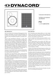
DIGITAL SYSTEM AMPLIFIER2 Installation2.1 Controls, Indicators and ConnectionsFRONT VIEWNumber Description1 Level Indicators for each channel2 Protection Indicator (PROT) for each channel3 Muting Indicator (MUTE) for each channel4 Power On/Off Indicator (POWER)5 Standby Indicator (STANDBY)6 Remote Amplifier Indicator (IRIS-Net)7 Mains SwitchREAR VIEWNumber Description1 Mains Input2 POWER REMOTE connector (POWER REMOTE)3 Power On Delay selection switch (ON DELAY)4 Power Amps Outputs (<strong>CH</strong> 1...4 / 5...8, BRIDGED)5 Power Amp Outputs Mode Switch (MODE) and Outputs Load Switch (OUTPUT)6 Input Level Control (LEVEL) for each channel7 Audio Inputs (INPUT) for each channel8 Expansion Slot (e.g. Remote Control Module RCM-810)9 Type Plate5
DIGITAL SYSTEM AMPLIFIER2.2 Operating Voltage2.4 MountingThe power amplifier receives its power supply via themains input. During installation, always separate thepower amplifier from the mains. Connect the power amplifieronly to a mains network, which corresponds to therequirements indicated on the type plate.Device Voltage Frequency Power Consumption<strong>DSA</strong> 8405 220-240 V AC / 120 50-60 Hz 490 WV AC / 100 V AC<strong>DSA</strong> 8405 220-240 V AC / 120 50-60 Hz 840 WV AC / 100 V AC<strong>DSA</strong> 8805 220-240 V AC / 120V AC / 100 V AC50-60 Hz 930 WTable 2-1: Operating Voltage<strong>DSA</strong> amplifiers have been designed for installation in aconventional 19-inch rack case. Attach the power ampwith its frontal rack mount ears using 4 screws and washersas shown in following illustration. Additionally securingthe amplifier at the rear becomes necessary, if therack case in which the power amplifier has been installedwill be transported. Failure to do so may result in damageto the power amplifier as well as to the rack case. Attachthe power amp as shown in the illustration using 4 casenuts and screws. RMK-15 brackets for securing the poweramplifier are available as accessories.Illustration 2-3: MountingMAINS OPERATION AND RESULTING TEMPERATUREThe power drawn from the mains network is convertedinto output power to feed the connected loudspeakersystems and into heat. The difference between powerconsumption and dispensed power is called power dissipation(P d ). The amount of heat resulting from power dissipationmight remain inside of a rack-shelf and needs tobe diverted using appropriate measures. The tables onpage 36 allow the determination of power supply and cablingrequirements. The tables are meant as auxiliarymeans for calculating temperatures inside of a rack-shelfsystem/cabinet and the ventilation efforts necessary.The column P d lists the leakage power in relation to differentoperational states. The column BTU/hr lists thedispensed heat amount per hour. The following factors allowdirect proportional calculation of the mains currentI mains for different mains supply voltages: 100 V = 2.3, 120V = 1.9, 220 V = 1.05, 240 V = 0.97.2.3 Mains SwitchThe Mains Switch on the front panel separates the poweramp from the mains. Turning the Mains Switch to ONstarts booting up the power amp. A soft start circuit compensatesmains inrush current peaks and thus preventsthe automatic cutout of the mains from reacting whenswitching on the power amplifier. Speaker systemswitch-on is delayed by approximately 4 seconds, effectivelysuppressing any possible power-on noise, whichotherwise might be heard through the loudspeakers.Illustration 2-2: Mains Switch2.5 VentilationAs with all <strong>Dynacord</strong> power amps with fan cooling, theairflow direction is front-to-rear, obviously because thereis more cold air outside of the rack case than inside. Thepower amplifier remains cooler and dissipating the developingwaste heat in a specific direction gets easier. Ingeneral, setting up or mounting the power amplifier hasto be done in a way that fresh air can enter unhindered atthe front and exhausted air can exit at the rear. When installingthe power amp in a case or rack system, attentionshould be paid to these details to provide sufficient ventilation.Allow for an air duct of at least 60 mm x 330 mmbetween the rear panel of the power amplifier and the innerwall of the cabinet/rack case. Make sure that the ductreaches up to the cabinet’s or the rack case’s top ventilationlouvers. Leave room of at least 100 mm above thecabinet/rack case for ventilation. Since temperatures insideof the cabinet/rack case can easily rise up to 40 °Cduring operation of the power amp, it is mandatory tobear in mind the maximum allowable ambient temperaturefor all other appliances installed in the same cabinet/rack case.6
DIGITAL SYSTEM AMPLIFIERIllustration 2-4: VentilationFor fixed amplifier installations in a device control roomthat incorporates a central air-cooling system or air conditioners,calculating the maximum heat emission may benecessary. Please also take notice of the information onpage 6.FAN COOLINGCAUTION:Blocking/closing the power amp’s ventilationlouvers is not permissible. Withoutsufficient cooling/ventilation, the poweramplifier may automatically enter protectmode. Keep ventilation louvers free fromdust to ensure unhindered airflow. Do notuse the power amplifier near heat sources,like heater blowers, stoves or any otherheat radiating devices. To ensure troublefreeoperation, make certain that the maximumallowable ambient temperature of+40°C is not exceeded.The power amplifier has two fans. The fans are temperaturecontrolled, i.e. they are not running permanently butthe running speed of the fans is controlled continuouslydepending on the ambient temperature. That in returnensures very silent running during idle state. The temperaturesof the power amp‘s channels are registered andmonitored separately.2.6 Selecting the Mode Of Operation (MODE)The MODE switch on the power amp‘s rear panel defines how the audio inputs handle the input signals. The amplifiertypes <strong>DSA</strong> 8405 and <strong>DSA</strong> 8410 allow the configuration of audio inputs <strong>CH</strong> 1/<strong>CH</strong> 2 or <strong>CH</strong> 3/<strong>CH</strong> 4, the amplifier type <strong>DSA</strong>8805 additionally allows configuration of audio <strong>CH</strong> 5/<strong>CH</strong> 6 or <strong>CH</strong> 7/<strong>CH</strong> 8.In the following description of the modes DUAL, PARALLEL or BRIDGED the generic letters A and B are used for the twoaudio inputs of a MODE switch (e.g. for switch <strong>CH</strong> 1/<strong>CH</strong> 2 input A corresponds to <strong>CH</strong> 1 and input B corresponds to <strong>CH</strong>2).DUALIn DUAL mode, the two channels of the power amplifier work independent from each other. This mode of operation isbeing used for all 2-channel applications, like stereo or Bi-Amp (active) operation. Using the input level controls on thepower amp’s rear panel allows independently adjusting the channels’ amplification.Illustration 2-5: Audio signal applied to both input connectors in DUAL modePARALLELIn PARALLEL mode, the inputs of channel A and channel B are directly electrically linked. The audio signal has to beapplied to the input connectors of channel A. Using the input level controls to independently control the amplificationof the two channels is still possible because only the channels’ inputs are linked. PARALLEL operation is the mode ofchoice, whenever the same input signal drives multiple power amp channels of a large system installation, e.g. whendriving massive bass arrays.CAUTION:In PARALLEL mode, the input signal has to be fed to input channel A only.7
DIGITAL SYSTEM AMPLIFIERIllustration 2-6: Audio signal applied to input A connector in PARALLEL modeBRIDGEDIn BRIDGED mode both amp channels work in push-pull operation to provide doubled output voltage. The audio signalhas to be applied to the input connectors of channel A, amplification is set via input level control of channel A only.BRIDGED operation is the mode of choice, whenever high power speakers are used. As the gain of the bridged amplifierchannels will be increased by 6 dB this will also result in a doubling of the output voltage. If an external limiter is beingused careful consideration should be given to its threshold setting. When using BRIDGED mode the recommendedthreshold setting of the external limiter must be reduced by 6 dB to ensure the same maximum voltage is delivered tothe speakers as when using DUAL/PARALLEL mode.Illustration 2-7: Audio signal applied to input A connector in BRIDGED modeCAUTION:In BRIDGED mode operation, it is not allowable for the load connected to fall below a value of 4 ohms.Extremely high voltages can be present at the output. The connected speaker systems must be able tohandle such voltages. Make sure to completely read and fully observe power rating specifications ofthe speaker systems to be used and to check them against the output power capacity of the poweramp.OUTPUT 2 4 70 V 100 V<strong>DSA</strong> 8405 4 8 1000 W at 140 V (20 ) 1000 W at 200 V (40 )<strong>DSA</strong> 8410 4 8 2000 W at 140 V (10 ) 2000 W at 200 V (20 )<strong>DSA</strong> 8805 4 8 1000 W at 140 V (20 ) 1000 W at 200 V (40 )Table 2-8: Minimum load in BRIDGED mode2.7 Selecting the Mode of Output (OUTPUT)Different output modes are available for the amplifier‘s output channels. Each channel can be switched to high impedancemode (HZ) for driving 70 V or 100 V loudspeakers without output transformers (Direct Drive).In DUAL or PARALLEL mode each output channel‘s OUTPUT setting can be independently set. In BRIDGED mode foreach pair of outputs only the OUTPUT setting of the channel with odd number (1, 3, 5 or 7) matters, the OUTPUT settingof the channel with even number (2, 4, 6 or 8) is ignored.Following section describes the four different OUTPUT settings of <strong>DSA</strong> amplifiers.8
DIGITAL SYSTEM AMPLIFIER2 OHM MODE / VLD MODEIn 2 Ohm mode the power amplifier reaches maximum output power having a load of 2 connected. Up to 4 cabinettshaving a nominal impedance of 8 each can be driven by each amplifier channel. This mode should be used if a highnumber of speaker with medium or low power rating should be driven in low impedance mode (LZ). The VLD mode (RemoteControl Module required) allows adjusting the output power of the amplifier channel. Please see page 10 for detailsabout VLD mode.Illustration 2-9: DUAL mode of <strong>CH</strong> 1 and <strong>CH</strong> 2 in 2 Ohm Mode4 OHM MODEIn 4 Ohm mode the power amplifier reaches maximum output power having a load of 4 connected. Up to 2 cabinettshaving a impedance of 8 each can be driven by each amplifier channel. This mode should be used if speakers withhigh power rating (e.g. Subwoofers) should be driven in low impedance mode (LZ).Illustration 2-10: DUAL mode of <strong>CH</strong> 1 and <strong>CH</strong> 2 in 4 Ohm Mode9
DIGITAL SYSTEM AMPLIFIER70 V MODEThe 70 V mode allows connection of 70 V loudspeaker lines (Direct Drive) in high impedance mode (HZ) without usingoutput transformers. In this case the maximum number of loudspeakers connected to an output channel is only limitedby the amplifier‘s output power (500 W for <strong>DSA</strong> 8405/8805 or 1000 W for <strong>DSA</strong> 8410). This mode should be used if thedistance between amplifier and speaker is larger than 50 metres (approx. 150 feet) and/or a high number of small speakerswith transformer (e.g. ceiling speakers) is used.Illustration 2-11: <strong>CH</strong> 1 in 70 V mode100 V MODEThe 100 V mode allows connection of 100 V loudspeaker lines (Direct Drive) in high impedance mode (HZ) without usingoutput transformers. In this case the maximum number of loudspeakers connected to an output channel is only limitedby the amplifier‘s output power (500 W for <strong>DSA</strong> 8405/8805 or 1000 W for <strong>DSA</strong> 8410). This mode should be used if thedistance between amplifier and speaker is larger than 50 metres (approx. 150 feet) and/or a high number of small speakerswith transformer (e.g. ceiling speakers) is used.Illustration 2-12: <strong>CH</strong> 1 in 100 V mode2.8 Variable Load Drive (VLD)Selecting an output mode, as described in the previouschapter, provides an extremely practical way of matchingamplifiers and connected loudspeaker systems. Table 2.3shows all possible combinations of output power andconnected load for power amps operated in low-impedancemode. Retrofitting an optionally available RemoteControl Module (e.g. RCM-810) allows freely programmingindividual amplifier channels via Variable Load Drive(VLD). For power amplifier models <strong>DSA</strong> 8405 and <strong>DSA</strong>8805 it is possible to freely select the output power in arange between 100 watts to 500 watts for loads rangingfrom 2 ohms to 10 ohms per channel. For the power amplifiermodel <strong>DSA</strong> 8410 it is possible to freely select theoutput power in a range between 100 watts to 1000watts for loads ranging from 2 ohms to 10 ohms per channel.Additionally, the Remote Control Module RCM-810allows switching a 50 Hz High-Pass filter on per channel.This may be advantageous when driving small or mediumsized full-range cabinets to eliminate unwanted sub-frequencycontent in the audio signal.For using VLD in a power amplifier with a Remote ControlModule installed, please proceed as follows:• Set the DIP-switch MODE (see page 7) to „2 /VLD“ for power amplifierchannels to be operated in VLD mode.• Use the DIP-switch OUTPUT (see page 8) to select DUAL or PARALLELoutput mode for power amplifier channels to be operated in VLDmode. VLD is not available in the BRIDGED output mode.• Use IRIS-Net (see page14) to configure output power, impedance andHigh-Pass filters of individual channels. Detailed information on theconfiguration, control and monitoring of amplifiers with RemoteControl Modules installed can be found in the documentation thatcomes with the IRIS-Net software application.The configuration of power amplifier channels is storednonvolatile in the Remote Control Module. Please keep inmind that the VLD configuration in IRIS-Net only affectschannels set to „2 /VLD“ mode. Operation modes 4ohms, 70 V and 100 V are not affected by VLD. Power amplifierchannels behave as described in chapter 2.7. Theuse of VLD considerably expands the adaptability of apower amplifier. Following table lists some applicationexamples of VLD.10
DIGITAL SYSTEM AMPLIFIER2 4 8 125 W 2 Mode <strong>DSA</strong> 8x05250 W 2 Mode <strong>DSA</strong> 8x05 4 Mode <strong>DSA</strong> 8x05 or 2 Mode <strong>DSA</strong> 8410500 W 2 Mode <strong>DSA</strong> 8x05 4 Mode <strong>DSA</strong> 8x05 or 2 Mode <strong>DSA</strong> 8410 4 Mode <strong>DSA</strong> 8410 or Bridge 2 <strong>DSA</strong> 8x051000 W 2 Mode <strong>DSA</strong> 8410 4 Mode <strong>DSA</strong> 8410 or Bridge 2 <strong>DSA</strong> 8x05 Bridge 4 <strong>DSA</strong> 8x05 or Bridge 2 <strong>DSA</strong> 84102000 W Bridge 2 <strong>DSA</strong> 8410 Bridge 4 <strong>DSA</strong> 8410Table 2-13: Maximum Output Power (VLD deactivated)2 4 8 125 W VLD, all types VLD, all types 2 Mode <strong>DSA</strong> 8x05 or VLD <strong>DSA</strong> 8410250 W VLD, all types 2 Mode <strong>DSA</strong> 8x05 or VLD <strong>DSA</strong> 8410 4 Mode <strong>DSA</strong> 8x05 or 2 Mode <strong>DSA</strong> 8410500 W VLD <strong>DSA</strong> 8410 or 2 Mode <strong>DSA</strong> 8x05 4 Mode <strong>DSA</strong> 8x05 or 2 Mode <strong>DSA</strong> 8410 VLD <strong>DSA</strong> 8x05 or 4 Mode <strong>DSA</strong> 8410 orBridge 2 <strong>DSA</strong> 8x051000 W 2 Mode <strong>DSA</strong> 8410 4 Mode <strong>DSA</strong> 8410 or Bridge 2 <strong>DSA</strong> 8x05 VLD <strong>DSA</strong> 8410 or Bridge 4 <strong>DSA</strong> 8x05 orBridge 2 <strong>DSA</strong> 84102000 W Bridge 2 <strong>DSA</strong> 8410 Bridge 4 <strong>DSA</strong> 8410Table 2-14: Maximum Output Power (VLD activated)2.9 Power on delayThe ON DELAY switch on the amplifier rear panel allows selection of the power on delay time. Following table showspossible switch settings and corresponding delay times in seconds.ON DELAY 0 1 2 3 4 5 6 7 8 9 A B C D E FDelay time (in s) 0 0.15 0.3 0.45 0.6 0.75 0.9 1.05 1.2 1.35 1.5 1.65 1.8 1.95 2.1 2.25CAUTION:The setting of ON DELAY is ignored if a Remote Control Module is assembled.2.10 Audio CablingINPUTInputs are electronically balanced. Whenever possible,using balanced audio signal feeds at the input of the poweramplifier is always preferred. Unbalanced connectionsshould only be used if the cables are very short and no interferingsignals are to be expected in the vicinity of thepower amplifier. In this case, bridging the screen (shielding)and the pin of the inverting input inside of the connectoris mandatory. Otherwise, a 6 dB drop in levelcould result. Please also see following illustration. Due totheir immunity against external interference sources,such as dimmers, mains connections, HF-control lines,etc., using balanced cabling and connections is alwayspreferable.Illustration 2-15: Balanced and unbalenced connection of input11
DIGITAL SYSTEM AMPLIFIEROUTPUT IN DUAL MODE OR PARALLEL MODESee illustration right for connecting speakers in DUAL orPARALLEL mode. Only connection of <strong>CH</strong> 1 and <strong>CH</strong> 2 isshown, the other channels have to be connected identically.The correct connection is also indicated at the amplifiersrear panel.Illustration 2-16: Output in DUAL mode or PARALLEL modeOUTPUT IN BRIDGED MODESee illustration right for connecting speakers in BRIDGEDmode. Only connection at <strong>CH</strong> 1/<strong>CH</strong> 2 is shown, the otherchannels have to be connected identically.The correct connection is also indicated at the amplifiersrear panel.Illustration 2-17: Output in BRIDGED modeCAUTION:In BRIDGED mode operation, it is notallowable for the load connected to fallbelow the values given in table 2.2 on page9. Extremely high voltages can be presentat the output. The connected speaker systemsmust be able to handle such voltages.Make sure to completely read and fullyobserve power rating specifications of thespeaker systems to be used and to checkthem against the output power capacity ofthe power amp.12
DIGITAL SYSTEM AMPLIFIER3 Operation3.1 Volume ControlIn DUAL and PARALLEL mode, the levelcontrols LEVEL on the power amp’srear panel are used to control the amplificationof the corresponding channel.The scale values are given in dB.Turning the control to the right increasesand turning it to the left decreases the volume. InBRIDGED mode operation, the output volume for a pair ofoutputs is only controlled by the level control of the channelwith odd number (1, 3, 5 or 7), the setting of the channelwith even number (2, 4, 6 or 8) is ignored.3.2 IndicationsPROTECTThe PROT LED lights indicating that oneof the internal protection circuitsagainst thermal overload, short-circuit, Back-EMF, HF-occurrenceat the output, etc., has been activated. In thatcase, the connected load is separated from the poweramps to prevent the connected loudspeaker systems andthe power amplifiers as well from being damaged. Whatevercaused the fault – e.g. a short-circuited speaker cable– needs to be remedied. In case of thermal overloadyou have to wait until the power amplifier automaticallyregains normal operation.MUTEThe MUTE LED lights red whenever thepower amp’s output signal is beingmuted, which happens when manually muting the outputsignal via IRIS-Net.-30DB...LIMITLevel indication is realized via verticalLED chains on the power amp’s frontpanel that individually indicate the actuallevels of each channel at -30dB, -10dB and -3dB below full modulation.The LIMIT LED lights as soon as the integrateddynamic audio limiter is activated and the poweramplifier is driven at the clipping limit or generally at itsmaximum capacity. Short-term blinking is not a problem,because the internal limiter controls input levels of up to+21 dBu down to a THD of approximately 1%. If, on theother hand, the LIMIT LED light constantly, reducing thevolume is recommended to prevent the loudspeaker systemsconnected from being damaged by probable overload.POWERThe POWER LED lights green when thepower amplifier is on. If the POWERLED does not light, despite the fact that the amplifier hasbeen switched on, this indicates that the power amp isnot connected to the mains or the primary fuse hasblown.STANDBYThe STANDBY LED lights yellow whenthe power amp is in standby mode.Standby mode reduces the amp’s power consumption toan absolute minimum. Activating the standby mode ispossible via IRISNet or the POWER REMOTE port at theamp‘s rear panel.IRIS-NETThe IRIS-Net LED lights blue if an IRIS-Net compatible remote control modulehas been installed in the power amp’s extension slot andsuccessful data communication has been established.The IRIS-Net LED blink slowly whenever the “Find” functionin IRIS-Net is being used to locate a power amplifierin the rack.3.3 Standby Mode (POWER REMOTE)POWER REMOTE providesa simple way toremotely power-on/offthe power amplifier.The POWER REMOTEfunction is only useful for appliances not employing a RemoteControl Modul. Controlling appliances with RemoteControl Module installed per REMOTE CONTROL is practicallypointless. Leaving the pins of POWER REMOTEsocket open the appliance power is switched on. Whenconnecting the pins the applicance enters standby mode.13
DIGITAL SYSTEM AMPLIFIER4 OptionsInstalling one of the optionally available extension modulesin the extension slot on the rear panel lets you expandthe power amp’s functional range. As an example,the following paragraphs describe the RCM-810 RemoteControl Module. Please read and follow the instructionsprovided in the documentation that you have received togetherwith each extension module.4.1 RCM-810SYSTEM DESCRIPTION AND FEATURESThe RCM-810 Remote Control Module is a digital controllermodule for live sound reinforcement, PA and fixed installationapplications. Installing the RCM-810 turns aconventional amp into a remote amplifier, which, at anytime, provides complete overview of the overall systemstatus and control of system parameters.RCM-810 modules allow the integration of amplifiers intoa remote control network with up to 100 devices. By usingmultiple networks within an IRIS-Net project up to250 amplifiers can be used in total. This offers the possibilityto control and monitor an entire PA system fromone or more PCs using the IRIS-Net - Intelligent Remote &Integrated Supervision - software package. All operationalstates, e.g. power-on status, temperature, activation ofprotections, load impedance, etc., are centrally registeredand displayed in IRIS-Net. This provides the possibilityto react and to selectively intervene even beforecritical operational states arise. Programming an automaticreaction, when specific thresholds are being exceededor fallen below, is also possible.Parameters, like power on/off, muting, etc. can be controlledin real-time and stored in the amplifier. In theevent of network failure or loss of power, all settings stayintact, independent of the control by the network.Furthermore, the RCM-810 provides a control port withfreely programmable control inputs and control outputs.Control inputs (GPI's) allow the connection of switches.IRIS-Net offers the possibility to program a variety of logicfunctions for the inputs. Control outputs (GPO's) allowthe connection of external components, which, for example,are used to signal specific states to peripheral equipment.For further details about configuration, control andmonitoring of amps with installed RCM-810 modules,please refer to the documentation of IRIS-Net. The latestversion of IRIS-Net is available at www.dynacord.com.14
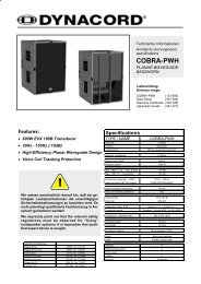
DIGITAL SYSTEM AMPLIFIERCONTROLS AND CONNECTIONSIllustration 4-1: Controls and Connections of the RCM-8101 INIT buttonThe INIT button allows resetting theRCM-810 to factory settings. Press thebutton for at least 3 seconds using e.g. asmall screwdriver. Following table lists the factory settingsof the RCM-810 module.CAUTION:All RCM-810 parameters configured viaIRIS-Net are discarded when pressing theINIT button.ParameterValueCAN-Bus data rate10 kbit/sPower-On-Delay0 msAmplifier & Channel LabelsRCM-810 Module, RCM-810 Input,RCM-810 OutputSupervisionnot configuredControl Ports and Job Numbers not configuredVLDdeactivatedTable 4-2: Factory settings of RCM-8102 CAN ADDRESS Selector SwitchThe two address selector switches arefor setting the network address of theRCM-810. CAN networks support addressesin the range of 01 to 250 (FAhex). Addressing has to be carried out inthe hexadecimal number system. The LOW selectorswitch sets the lower digit, while HIGH sets the higherdigit.CAUTION:Each address may exist only once in a system.Otherwise, network conflicts mayarise.HIGH LOW Address0 0 Stand-alone0 1...F 1...151 0...F 16...312 0...F 32...473 0...F 48...634 0...F 64...795 0...F 80...956 0...F 96...1117 0...F 112...127Table 4-3: CAN addressesAddress 0 (00 hex, delivery status) disables remote communicationbetween the RCM-810 and the bus. The moduledoes not appear in the system, even though it isphysically connected to the CAN-bus.3 STATUS LEDHIGH LOW Address8 0...F 128...1439 0...F 144...159A 0...F 160...175B 0...F 176...191C 0...F 192...207D 0...F 208...223E 0...F 224...239F 0...A 240...250F B...F reservedTable 4-3: CAN addressesThe STATUS LED is for monitoring thecommunication on the CAN bus. The LEDblinks rhythmically every 3 seconds, when the module’saddress is set to “00“, which means that it is disconnectedfrom the CAN bus and software control. The LEDblinks rhythmically in intervals of one second, when anaddress in the range of 01 to 250 has been assigned tothe module and there has not yet been any activity on theCAN bus. As soon as communication on the CAN bus isrecognized, the LED lights for at least 100 ms, when thepower amplifier sends data on the CAN bus.4 REMOTE CAN BUS ConnectionThe RCM-810 module provides two RJ-45sockets for connecting to the REMOTECAN BUS. These sockets are connectedin parallel and serve as inputs as well asfor daisy-chaining the devices on the remotenetwork. Cabling in a rack systemcan be established using commerciallyavailable RJ-45 network cables. However,CAN guidelines have to be observedfor longer cable lengths. Both ends of the CAN bus mustbe terminated using 120 terminating plugs.The CAN bus allows using different data rates, whereasthe data rate is inversely proportional to the bus length.For smaller network setups, data rates can be as high as500 kbit/s. For broader networks, reducing the data ratebecomes necessary (down to the minimum data rate of10 kbit/s).HINT: The data rate of the CAN bus is preset to 10kbit/s.The following table illustrates the relation between datarate and bus length or network size. The use of CAN repeatersis strongly recommended for busses that exceed1000 meters in length.Transfer rate (in kbit/s) Bus length (in m)500 100250 250125 500Table 4-4: Transfer rate and bus length15
DIGITAL SYSTEM AMPLIFIERTransfer rate (in kbit/s) Bus length (in m)62,5 100020 250010 5000Table 4-4: Transfer rate and bus lengthIllustration 4-5: Pin-assignment of CAN jack and CAN plug5 CONTROL PORTThe CONTROL PORT of the RCM-810provides two control inputs, two controloutputs and reference connections for+5V and ground. The control inputs areconfigurable via IRIS-Net. They can beused for example for switching betweenpower on / standby modes. The two controlcontacts IN 1 and IN 2 are internallyconnected via pull-up resistors and carry+5V (open). The control inputs can be activated using externalswitches, pushbuttons or relays to connect themto ground potential. The two control outputs OUT 1 andOUT 2 are open collector outputs, which are highly resistivein the non-active state (off). In active state (on) theoutputs are connected to ground. The control outputs areconfigurable via IRIS-Net and are used to signal internalstates. LEDs, indicators or relays can be driven directly.The +5V reference connector provides voltage supply forconnected components.CAUTION: The maximally allowable current at the +5Voutput is 200 mA.16
DIGITAL SYSTEM AMPLIFIER17
DIGITAL SYSTEM AMPLIFIERINHALTEINFÜHRUNG . . . . . . . . . . . . . . . . . . . . . . . . . . . . . . . . . . . . . . . . . . . . . . . . . . . . . . . . . . . . . . . . . . . . . . . . . . . . . . .20Auspacken und Überprüfen . . . . . . . . . . . . . . . . . . . . . . . . . . . . . . . . . . . . . . . . . . . . . . . . . . . . . . . . . . . . . .20Lieferumfang und Garantie . . . . . . . . . . . . . . . . . . . . . . . . . . . . . . . . . . . . . . . . . . . . . . . . . . . . . . . . . . . . . . .20Verantwortung des Betreibers . . . . . . . . . . . . . . . . . . . . . . . . . . . . . . . . . . . . . . . . . . . . . . . . . . . . . . . . . . . .20INSTALLATION . . . . . . . . . . . . . . . . . . . . . . . . . . . . . . . . . . . . . . . . . . . . . . . . . . . . . . . . . . . . . . . . . . . . . . . . . . . . . .21Bedienelemente, Anzeigen und Anschlüsse . . . . . . . . . . . . . . . . . . . . . . . . . . . . . . . . . . . . . . . . . . . . . . . . . .21Betriebsspannung . . . . . . . . . . . . . . . . . . . . . . . . . . . . . . . . . . . . . . . . . . . . . . . . . . . . . . . . . . . . . . . . . . . . . .22Netzschalter . . . . . . . . . . . . . . . . . . . . . . . . . . . . . . . . . . . . . . . . . . . . . . . . . . . . . . . . . . . . . . . . . . . . . . . . . .22Einbau . . . . . . . . . . . . . . . . . . . . . . . . . . . . . . . . . . . . . . . . . . . . . . . . . . . . . . . . . . . . . . . . . . . . . . . . . . . . . . .22Kühlung . . . . . . . . . . . . . . . . . . . . . . . . . . . . . . . . . . . . . . . . . . . . . . . . . . . . . . . . . . . . . . . . . . . . . . . . . . . . . .23Wahl der Betriebsart (MODE) . . . . . . . . . . . . . . . . . . . . . . . . . . . . . . . . . . . . . . . . . . . . . . . . . . . . . . . . . . . . .23Wahl des Ausgangs-Modus (OUTPUT) . . . . . . . . . . . . . . . . . . . . . . . . . . . . . . . . . . . . . . . . . . . . . . . . . . . . . .25Variable Load Drive (VLD) . . . . . . . . . . . . . . . . . . . . . . . . . . . . . . . . . . . . . . . . . . . . . . . . . . . . . . . . . . . . . . .27Einschaltverzögerung . . . . . . . . . . . . . . . . . . . . . . . . . . . . . . . . . . . . . . . . . . . . . . . . . . . . . . . . . . . . . . . . . . .27Audio Verkabelung . . . . . . . . . . . . . . . . . . . . . . . . . . . . . . . . . . . . . . . . . . . . . . . . . . . . . . . . . . . . . . . . . . . . .28BETRIEB . . . . . . . . . . . . . . . . . . . . . . . . . . . . . . . . . . . . . . . . . . . . . . . . . . . . . . . . . . . . . . . . . . . . . . . . . . . . . . . . . .29Eingangspegel-Regler . . . . . . . . . . . . . . . . . . . . . . . . . . . . . . . . . . . . . . . . . . . . . . . . . . . . . . . . . . . . . . . . . . .29Anzeigen . . . . . . . . . . . . . . . . . . . . . . . . . . . . . . . . . . . . . . . . . . . . . . . . . . . . . . . . . . . . . . . . . . . . . . . . . . . . .29Standby-Modus (POWER REMOTE) . . . . . . . . . . . . . . . . . . . . . . . . . . . . . . . . . . . . . . . . . . . . . . . . . . . . . . . .29OPTIONEN . . . . . . . . . . . . . . . . . . . . . . . . . . . . . . . . . . . . . . . . . . . . . . . . . . . . . . . . . . . . . . . . . . . . . . . . . . . . . . . . .30RCM-810 . . . . . . . . . . . . . . . . . . . . . . . . . . . . . . . . . . . . . . . . . . . . . . . . . . . . . . . . . . . . . . . . . . . . . . . . . . . . .30SPECIFICATIONS/TE<strong>CH</strong>NIS<strong>CH</strong>E DATEN . . . . . . . . . . . . . . . . . . . . . . . . . . . . . . . . . . . . . . . . . . . . . . . . . . . . . . . . . . . . .33<strong>DSA</strong> 8405 . . . . . . . . . . . . . . . . . . . . . . . . . . . . . . . . . . . . . . . . . . . . . . . . . . . . . . . . . . . . . . . . . . . . . . . . . . . .33<strong>DSA</strong> 8410 . . . . . . . . . . . . . . . . . . . . . . . . . . . . . . . . . . . . . . . . . . . . . . . . . . . . . . . . . . . . . . . . . . . . . . . . . . . .34<strong>DSA</strong> 8805 . . . . . . . . . . . . . . . . . . . . . . . . . . . . . . . . . . . . . . . . . . . . . . . . . . . . . . . . . . . . . . . . . . . . . . . . . . . .35Mains Operation & Resulting Temperature . . . . . . . . . . . . . . . . . . . . . . . . . . . . . . . . . . . . . . . . . . . . . . . . . . .36Block Diagram / Blockschaltbild . . . . . . . . . . . . . . . . . . . . . . . . . . . . . . . . . . . . . . . . . . . . . . . . . . . . . . . . . . .38Dimensions / Abmessungen . . . . . . . . . . . . . . . . . . . . . . . . . . . . . . . . . . . . . . . . . . . . . . . . . . . . . . . . . . . . . .3918
DIGITAL SYSTEM AMPLIFIERWI<strong>CH</strong>TIGE SI<strong>CH</strong>ERHEITSHINWEISEDas Blitzsymbol innerhalb eines gleichseitigenDreiecks soll den Anwender auf nicht isolierte Leitungenund Kontakte im Geräteinneren hinweisen,an denen hohe Spannungen anliegen, die im Falleiner Berührung zu lebensgefährlichen Stromschlägenführen können.Das Ausrufezeichen innerhalb eines gleichseitigenDreiecks soll den Anwender auf wichtige Bedienungs-sowie Servicehinweise in der zum Gerätgehörenden Literatur aufmerksam machen.1. Lesen Sie diese Hinweise.2. Heben Sie diese Hinweise auf.3. Beachten Sie alle Warnungen.4. Richten Sie sich nach den Anweisungen.5. Betreiben Sie das Gerät nicht in unmittelbarer Nähe von Wasser.6. Verwenden Sie zum Reinigen des Gerätes ausschließlich ein trockenes Tuch.7. Verdecken Sie keine Lüftungsschlitze. Beachten Sie bei der Installation des Gerätes stets die entsprechenden Hinweise des Herstellers.8. Vermeiden Sie die Installation des Gerätes in der Nähe von Heizkörpern, Wärmespeichern, Öfen oder anderer Wärmequellen.9. Achtung: Gerät nur an Netzsteckdose mit Schutzleiteranschluss betreiben. Setzen Sie die Funktion des Schutzleiteranschlusses desmitgelieferten Netzanschlusskabels nicht außer Kraft. Sollte der Stecker des mitgelieferten Kabels nicht in Ihre Netzsteckdose passen, setzenSie sich mit Ihrem Elektriker in Verbindung.10. Sorgen Sie dafür, dass das Netzkabel nicht betreten wird. Schützen Sie das Netzkabel vor Quetschungen insbesondere am Gerätestecker undam Netzstecker.11. Verwenden Sie mit dem Gerät ausschließlich Zubehör/Erweiterungen, die vom Hersteller hierzu vorgesehen sind.12. Verwenden Sie zusammen mit dieser Komponente nur vom Hersteller dazu vorgesehene oder andere geeignete Lastkarren,Stative, Befestigungsklammern oder Tische, die Sie zusammen mit dem Gerät erworben haben. Achten Sie beim Transport mittelsLastkarren darauf, dass das transportierte Equipment und der Karren nicht umfallen und möglicherweise Personen- und/oderSachschäden verursachen können.13. Ziehen Sie bei Blitzschlaggefahr oder bei längerem Nichtgebrauch den Netzstecker.14. Überlassen Sie sämtliche Servicearbeiten und Reparaturen einem ausgebildeten Kundendiensttechniker. Servicearbeiten sindnotwendig, sobald das Gerät auf irgendeine Weise beschädigt wurde, wie z.B. eine Beschädigung des Netzkabels oder des Netzsteckers, wenneine Flüssigkeit in das Gerät geschüttet wurde oder ein Gegenstand in das Gerät gefallen ist, wenn das Gerät Regen oder Feuchtigkeitausgesetzt wurde, oder wenn es nicht normal arbeitet oder fallengelassen wurde.15. Stellen Sie bitte sicher, dass kein Tropf- oder Spritzwasser ins Geräteinnere eindringen kann. Platzieren Sie keine mit Flüssigkeiten gefülltenObjekte, wie Vasen oder Trinkgefäße, auf dem Gerät.16. Um das Gerät komplett spannungsfrei zu schalten, muss der Netzstecker gezogen werden.17. Beim Einbau des Gerätes ist zu beachten, dass der Netzstecker leicht zugänglich bleibt.18. Stellen Sie keine offenen Brandquellen, wie z.B. brennende Kerzen auf das Gerät.19. Dieses S<strong>CH</strong>UTZKLASSE I Gerät muss an eine NETZ-Steckdose mit Schutzleiter-Anschluss angeschlossen werden.WI<strong>CH</strong>TIGE SERVICEHINWEISEA<strong>CH</strong>TUNG: Diese Servicehinweise sind ausschließlich zur Verwendung durch qualifiziertes Servicepersonal. Um die Gefahreines elektrischen Schlages zu vermeiden, führen Sie keine Wartungsarbeiten durch, die nicht in derBedienungsanleitung beschrieben sind, außer Sie sind hierfür qualifiziert. Überlassen Sie sämtlicheServicearbeiten und Reparaturen einem ausgebildeten Kundendiensttechniker.1. Bei Reparaturarbeiten im Gerät sind die Sicherheitsbestimmungen nach EN 60065 (VDE 0860) einzuhalten.2. Bei allen Arbeiten, bei denen das geöffnete Gerät mit Netzspannung verbunden ist und betrieben wird, ist ein Netz-Trenntransformator zuverwenden.3. Vor einem Umbau mit Nachrüstsätzen, Umschaltung der Netzspannung oder sonstigen Modifikationen ist das Gerät stromlos zu schalten.4. Die Mindestabstände zwischen netzspannungsführenden Teilen und berührbaren Metallteilen (Metallgehäuse) bzw. zwischen den Netzpolenbetragen 3 mm und sind unbedingt einzuhalten.5. Die Mindestabstände zwischen netzspannungsführenden Teilen und Schaltungsteilen, die nicht mit dem Netz verbunden sind (sekundär),betragen 6 mm und sind unbedingt einzuhalten.6. Spezielle Bauteile, die im Stromlaufplan mit dem Sicherheitssymbol gekennzeichnet sind, (Note) dürfen nur durch Originalteile ersetzt werden.7. Eigenmächtige Schaltungsänderungen dürfen nicht vorgenommen werden.8. Die am Reparaturort gültigen Schutzbestimmungen der Berufsgenossenschaften sind einzuhalten. Hierzu gehört auch die Beschaffenheit desArbeitsplatzes.9. Die Vorschriften im Umgang mit MOS-Bauteilen sind zu beachten.NOTE:SAFETY COMPONENT (MUST BE REPLACED BY ORIGINAL PART)Hinweise zur Entsorgung/Wiederverwendung gemäß WEEEDas auf unserem Produkt und im Handbuch abgedruckte Mülltonnensymbol weist daraufhin, dass dieses Produkt nicht gemeinsam mit dem Haushaltsmüll entsorgt werden darf. Fürdie korrekte Entsorgung der Elektro- und Elektronik-Altgeräte (WEEE) am Ende ihrer Nutzungsdauer ist in unserer Kategorie der Hersteller verantwortlich. Aufgrundunterschiedlicher Regelungen zur WEEE-Umsetzung in den einzelnen EU-Staaten bitten wir Sie, sich an Ihren örtlichen Händler zu wenden. Wir haben ein eigenes System zurVerarbeitung elektronischer Abfälle und gewährleisten die kostenfreie Entgegennahme aller Produkte der EVI Audio GmbH: Telex, DYNACORD, Electro-Voice und RTS. Wir haben mitdem Händler, bei dem Sie Ihr Produkt gekauft haben, eine Vereinbarung getroffen, dass alle nicht mehr verwenbaren Geräte zur umweltgerechten Entsorgung kostenfrei an das Werkin Straubing zurückgeschickt werden.Bitte kontaktieren Sie vor dem Anschluss an die Spannungsversorgung Ihr Energieversorgungsunternehmen bezüglich Oberwellen.19
DIGITAL SYSTEM AMPLIFIER1 EinführungMit den Endstufen der <strong>DSA</strong>-Serie von <strong>Dynacord</strong> beginntein neues Zeitalter in der Endstufen-Technologie. Die hocheffizienteTechnik der <strong>DSA</strong>-Endstufe liefert kompromissloseAudioperformance bei geringem Gewichtund höchster Zuverlässigkeit.1.1 Auspacken und ÜberprüfenÖffnen Sie die Verpackung und entnehmen Sie die Endstufe.Überprüfen Sie die Endstufe auf äußere Beschädigungen,die während des Transports zu Ihnenaufgetreten sein könnten. Jede Endstufe wird vor Verlassendes Werks eingehend untersucht und getestet undsollte in einwandfreiem Zustand bei Ihnen ankommen.Falls die Endstufe Beschädigungen aufweist, benachrichtigenSie bitte unverzüglich das Transportunternehmen.Ein Transportschaden kann nur von Ihnen, demEmpfänger, reklamiert werden. Bewahren Sie den Kartonund das Verpackungsmaterial zwecks Besichtigung durchdas Transportunternehmen auf. Die Aufbewahrung desKartons samt Verpackungsmaterial wird auch dannangeraten, wenn die Endstufe keine Beschädigungaufweist.A<strong>CH</strong>TUNG: Versenden Sie die Endstufe nie ohne dasoriginal Verpackungsmaterial.Wenn Sie die Endstufe versenden, verwenden Sie stetsden Originalkarton und das original Verpackungsmaterial.Für bestmöglichen Schutz vor Transportschäden verpakkenSie die Endstufe wie sie ursprünglich im Werk verpacktwurde.1.3 Verantwortung des BetreibersBES<strong>CH</strong>ÄDIGUNG VON LAUTSPRE<strong>CH</strong>ERNDie <strong>DSA</strong>-Endstufe verfügt über eine hohe Ausgangsleistungund kann sowohl für Menschen als auch für angeschlosseneLautsprecher eine Gefahr darstellen.Lautsprecher können durch zu hohe Leistung beschädigtoder zerstört werden, vor allem durch die hohe Leistungder <strong>DSA</strong>-Endstufe im Brückenbetrieb. Informieren Siesich immer über die Dauer- und Spitzenbelastbarkeit deranzuschließenden Lautsprecher. Selbst wenn mittels derEingangspegel-Regler an der Rückseite der Endstufe dieVerstärkung reduziert wird, ist es bei ausreichend hohemEingangssignal noch immer möglich, die volle Ausgangsleistungzu erreichen.GEFAHREN AM LAUTSPRE<strong>CH</strong>ERAUSGANGDie <strong>DSA</strong>-Endstufe ist in der Lage, gefährlich hohe Spannungenam Ausgang zu produzieren. Zur Vermeidungeines Stromschlags berühren Sie keinesfalls blanke Lautsprecherleitungenwährend des Betriebs der Endstufe.1.2 Lieferumfang und Garantie• 1 Endstufe• 1 Handbuch (dieses Dokument)• 1 Netzkabel• 1 (<strong>DSA</strong> 8405 / 8410) bzw. 2 (<strong>DSA</strong> 8805) Schraub-Steckverbinder8-polig für Endstufenausgang• 2 (<strong>DSA</strong> 8405 / 8410) bzw. 4 (<strong>DSA</strong> 8805) Schraub-Steckverbinder6-polig für Endstufeneingang• 1 Power Remote Stecker, 2-polig• 1 GarantiekarteBewahren Sie neben der Garantiekarte auch denKaufbeleg, der den Termin der Übergabe festlegt, auf.Das Werk leistet Garantie für alle nachweisbaren Material-und Fertigungsfehler für die Dauer von 36 Monatenab Verkauf. Garantieleistungen werden nur dannanerkannt, wenn gültige, d.h. vollständig ausgefüllte Garantieunterlagenvorliegen. Von der Garantie ausgenommensind alle Schäden, die durch falsche oderunsachgemäße Bedienung verursacht werden. BeiFremdeingriffen oder eigenmächtigen Änderungen erlischtjeder Garantieanspruch.20
DIGITAL SYSTEM AMPLIFIER2 Installation2.1 Bedienelemente, Anzeigen und AnschlüsseFRONTSEITENummer Beschreibung1 Pegelanzeige für Kanäle 1 bis 4 (<strong>DSA</strong> 8405/8410) bzw. 8 (<strong>DSA</strong> 8805)2 Anzeige Schutzschaltung (PROT)3 Anzeige Stummschaltung (MUTE)4 Anzeige Betrieb (POWER)5 Anzeige Standby (STANDBY)6 Anzeige Remote Amplifier (IRIS-Net)7 NetzschalterRÜCKSEITENummer Beschreibung1 Netzeingang2 POWER REMOTE-Buchse (POWER REMOTE)3 Einschaltverzögerungs-Wahlschalter (ON DELAY)4 Endstufenausgangsklemmen (<strong>CH</strong> 1...4 / 5...8, BRIDGED)5 Schalter Endstufen-Betriebsart (MODE) und Ausgangs-Modus (OUTPUT)6 Eingangspegel-Regler je Kanal (LEVEL)7 Audioeingang (INPUT) je Kanal8 Erweiterungssteckplatz (z. B. Remote Control Module RCM-810)9 Typenschild21
DIGITAL SYSTEM AMPLIFIER2.2 Betriebsspannung2.4 EinbauDie Spannungsversorgung der Endstufe erfolgt über dieNetzeingangsbuchse. Trennen Sie die Endstufe währendder Installation immer von der Netzversorgung. SchließenSie die Endstufe nur an eine geeignete Netzversorgungan, die den auf dem Typenschild angegebenen Anforderungenentspricht.Die <strong>DSA</strong>-Endstufe wurde für den Einbau in ein konventionelles19-Zoll Rack entwickelt. Befestigen Sie die Endstufean der Vorderseite mit 4 Schrauben undUnterlegscheiben wie in folgender Abbildung dargestellt.Abbildung 2-3: Befestigung der Endstufe bei RackeinbauGerät Spannung Netzfrequenz<strong>DSA</strong> 8405 220-240 V AC / 120 V AC /100 V AC<strong>DSA</strong> 8405 220-240 V AC / 120 V AC /100 V AC<strong>DSA</strong> 8805 220-240 V AC / 120 V AC /100 V ACTabelle 2-1: Operating VoltageLeistungsaufnahme50-60 Hz 490 W50-60 Hz 840 W50-60 Hz 930 WNETZBETRIEB UND WÄRMEENTWICKLUNG IN DER ENDSTUFEMit Hilfe der Tabellen ab Seite 36 können dieAnforderungen an Stromversorgung und Zuleitungen bestimmtwerden. Die vom Stromnetz aufgenommene Leistungwird in Ausgangsleistung für die Lautsprecher und inWärme umgewandelt. Die Differenz aus aufgenommenerLeistung und abgegebener Leistung nennt man Verlustleistung(Pd). Die durch Verluste entstehende Wärme verbleibtu. U. im Rack und muss durch geeigneteMaßnahmen abgeleitet werden. Zur Berechnung der Wärmeverhältnisseim Rack/Schrank bzw. zur Dimensionierungeventuell benötigter Abluftmaßnahmen könnenebenfalls die Tabellen ab Seite 36 benutzt werden. DieSpalte P d zeigt die Verlustleistung bei verschiedenen Betriebszuständen.Die Spalte BTU/hr zeigt die abgegebeneWärmemenge je Stunde. Die Stromaufnahmen für andereNetze können mit folgenden Faktoren direkt proportionalumgerechnet werden: 100 V = 2.3, 120 V = 1.9, 220 V =1.05, 240 V = 0.97.Wird das Rack, in dem die Endstufe eingebaut ist, transportiert,muss die Rückseite der Endstufe im Rack befestigtwerden. Bei fehlender Befestigung kann sowohl dieEndstufe als auch das Rack beschädigt werden. BefestigenSie die Endstufe wie in folgender Abbildung gezeigtmit Hilfe von Käfigmuttern und Befestigungsschrauben.Geeignete Rackwinkel RMK-15 sind als Zubehör erhältlich.2.5 Kühlung2.3 NetzschalterDer Netzschalter POWER an der Frontseite trennt inSchalterstellung OFF die Endstufe von der Netzversorgung.In Schalterstellung ON wird das Hochfahren derEndstufe gestartet. Eine Softstart-Schaltung vermeidetdabei Einschaltstromspitzen auf der Netzleitung.Dadurch wird verhindert, dass der Leitungsschutz-schalterdes Stromnetzes beim Einschalten der Endstufe anspricht.Die Lautsprecher werden um ca. 4 Sekundenverzögert zugeschaltet. Hierdurch werden etwaige Einschaltgeräuscheeffektiv unterdrückt, die ansonsten inden Lautsprechern hörbar wären.Bei allen lüftergekühlen Endstufen von DYNACORDströmt die Luft von der Frontseite zur Rückseite, da kühleFrischluft eher außerhalb des Racks zur Verfügung stehtals innerhalb. Die Endstufe bleibt kühler und die entstehendeAbwärme kann gezielter abgeführt werden.Abbildung 2-4: KühlungAbbildung 2-2: Netzschalter22
DIGITAL SYSTEM AMPLIFIERGenerell ist die Endstufe so aufzustellen oder zu montieren,dass die Luftzufuhr an der Frontseite und die Entlüftungan der Geräterückseite nicht behindert wird. Fürden Einbau in Gehäuse und Racks ist zu beachten, dasseine ausreichende Belüftung der Endstufe möglich ist.Zwischen der Endstufen-Rückseite und der Schrank/Rack-Innenseite ist ein freier Luftkanal von mindestens60 mm x 330 mm bis zur oberen Rack- oder Schrankentlüftungvorzusehen. Oberhalb des Schrankes soll einfreier Raum von mindestens 100 mm für die Entlüftungvorgesehen werden. Da während des Betriebs der Endstufedie Temperatur im Gehäuse- oder Schrank auf biszu 40 °C ansteigen kann, muss die maximal zulässigeUmgebungstemperatur der übrigen im Gestellschrankbefindlichen Geräte beachtet werden.Endstufen der <strong>DSA</strong> Serie können in Racks ohne Abstanddirekt übereinander montiert werden. Da sich die Gehäuseder <strong>DSA</strong> Verstärker im Betrieb erwärmen, kann esjedoch sinnvoll sein zu anderen Geräten ohne Zwangskühlung(Controller, System Manager etc.) 1 Höheneinheit(1 HE) Abstand zu halten.A<strong>CH</strong>TUNG: Die Lüftungsöffnungen der Endstufe dürfennicht blockiert/verschlossen werden.Bei fehlender Kühlung kann sich die Endstufeautomatisch abschalten. Halten Siealle Lüftungsöffnungen frei vonStaubablagerungen, die den Luftstrombehindern würden. Betreiben Sie die Endstufenicht in der Nähe von Wärmequellenwie Heizlüftern, Öfen oder anderen Geräten,die Hitze abstrahlen. Die maximaleUmgebungstemperatur von +40°C soll fürstörungsfreien Betrieb nicht über-schrittenwerden.Für Installationen mit einem zentralen Kühlluftsystemoder Klimageräten, wie es häufig bei Festinstallationen inspeziellen Geräteräumen verwendet wird, kann es nötigsein die maximale Wärme-Emission zu berechnen.Beachten Sie hierzu die Hinweise auf Seite 22.LÜFTERDie Endstufen der <strong>DSA</strong>-Serie besitzen zwei Lüfter. Es erfolgtkeine Dauerlüftung der Endstufe sondern eine temperaturabhängige,stufenlose Geschwindigkeitsregelungder einzelnen Lüfter. Hierdurch wird eine sehr geringeGeräuschentwicklung im Ruhebetrieb erreicht. Die Temperaturender Endstufe werden kanalweise getrennt erfasstund überwacht.2.6 Wahl der Betriebsart (MODE)Die Stellung des MODE Schalters an der Rückseite der Endstufe bestimmt die Schaltung der Audioeingänge. Bei denEndstufen-Typen <strong>DSA</strong> 8405 und <strong>DSA</strong> 8410 kann die Schaltung der Audioeingänge <strong>CH</strong> 1/<strong>CH</strong> 2 bzw. <strong>CH</strong> 3/<strong>CH</strong> 4 konfiguriertwerden, beim Endstufen-Typ <strong>DSA</strong> 8805 sind zusätzlich die Audioeingänge <strong>CH</strong> 5/<strong>CH</strong> 6 bzw. <strong>CH</strong> 7/<strong>CH</strong> 8 konfigurierbar.In den folgenden Beschreibungen der Schalterstellungen DUAL, PARALLEL bzw. BRIDGED sind die beidenAudioeingänge der MODE Schalter jeweils mit Kanal A bzw. B bezeichnet (Beispiel: Für Schalter <strong>CH</strong> 1/<strong>CH</strong> 2 entsprichtA dem <strong>CH</strong> 1 und B dem <strong>CH</strong> 2).DUALIn der Betriebsart DUAL arbeiten die Kanalpaare unabhängig voneinander. Diese Betriebsart wird bei allen 2-kanaligenAnwendungen wie Stereobetrieb oder der Beschallung von getrennten Zonen verwendet. Über die Eingangspegel-Regleran der Rückseite der Endstufe lässt sich die Verstärkung der Kanäle getrennt justieren.Abbildung 2-5: Einspeisung an beiden Eingängen bei Betriebsart DUAL23
DIGITAL SYSTEM AMPLIFIERPARALLELIn der Betriebsart PARALLEL sind die Eingänge der Kanäle A und B direkt elektrisch verbunden (gelinkt). Das Eingangssignalist über den Eingang des Kanals A zuzuführen. Da nur die Eingänge der beiden Kanäle miteinander verbunden sind,lässt sich weiterhin über die Eingangspegel-Regler die Verstärkung der beiden Endstufenkanäle getrennt einstellen. DieBetriebsart PARALLEL empfiehlt sich dann, wenn in größeren Anlagen mehrere Endstufenkanäle mit dem gleichen Signalangesteuert werden sollen, z. B. beim Antrieb von größeren Bassarrays.Abbildung 2-6: Einspeisung an Eingang A bei Betriebsart PARALLELA<strong>CH</strong>TUNG: In der Betriebsart PARALLEL kann nur am Eingangskanal A ein Signal eingespeist werden.BRIDGEDIn der Betriebsart BRIDGED arbeiten die gebrückten Kanäle als einkanaliger Mono-Block. Das Eingangssignal ist überden Eingang des Kanals A zuzuführen, die Eingänge des Kanals B sind inaktiv. Bei dieser Betriebsart wird die Endstufeim Kanal A ganz normal angesteuert. Zusätzlich wird das Signal intern invertiert und auf die Endstufe im Kanal B gelegt.Die Endstufen A und B arbeiten dann im Gegentakt mit verdoppelter Ausgangsspannung. Diese Verdoppelung der Ausgangsspannungist bei der Verwendung von externen Limitern zu berücksichtigen, da im Brückenbetrieb das jeweiligeKanalpaar 6 dB mehr Verstärkung als eine Einzelkanal hat. Der Threshold eines externen Limiters muss demnach um6 dB niedriger eingestellt werden, um am Lautsprecher wieder auf die gleiche maximale Spannung zu begrenzen.Abbildung 2-7: Betriebsart BRIDGEDA<strong>CH</strong>TUNG: In der Betriebsart BRIDGED darf die angegebene minimale Last nicht unterschritten werden. Die infolgender Tabelle angegebenen Werte müssen beachtet werden. Es können sehr hohe Spannungen amAusgang produziert werden. Die angeschlossenen Lautsprecher müssen für derart hohe Spannungenausgelegt sein. Beachten Sie unbedingt die Leistungsangaben im Datenblatt des jeweiligen Lautsprechersund vergleichen Sie diese mit der entsprechenden Ausgangsleistung der Endstufe.Ausgangs-Modus 2 4 70 V 100 V<strong>DSA</strong> 8405 4 8 1000 W an 140 V (20 ) 1000 W an 200 V (40 )<strong>DSA</strong> 8410 4 8 2000 W an 140 V (10 ) 2000 W an 200 V (20 )<strong>DSA</strong> 8805 4 8 1000 W an 140 V (20 ) 1000 W an 200 V (40 )Tabelle 2-8: Minimal zulässige Last im Brückenbetrieb24
DIGITAL SYSTEM AMPLIFIER2.7 Wahl des Ausgangs-Modus (OUTPUT)Die Endstufenkanäle der Endstufen <strong>DSA</strong> 8405/8410/8805 können auf verschiedene Ausgangsmodi umgeschaltet werden.Bei Bedarf kann jeder Kanal einzeln auf Hochimpedanzbetrieb (HZ) umgeschaltet werden, um 70 V und 100 V Lautsprecherliniendirekt ohne Ausgangsübertrager (Direct Drive) anzutreiben. In den Betriebsarten DUAL und PARALLELeines Ausgangskanal-Paares können die Ausgangs-Modi der Ausgangskanäle unabhängig voneinander eingestellt werden.In der Betriebsart BRIDGED eines Ausgangskanal-Paares ist nur die OUTPUT-Einstellung des Kanals mit ungeraderNummer (also 1, 3, 5 bzw. 7) relevant, die OUTPUT-Einstellung des Kanals mit gerader Nummer (also 2, 4, 6 bzw. 8) wirdignoriert.Im Folgenden werden die vier verschiedenen Ausgangsmodi beschrieben und mit Abbildungen verdeutlicht.2 OHM /VLD-MODUSIm 2 Ohm-Modus erreicht die Endstufe die maximale Ausgangsleistung bei einer Last von 2 . Es können zum Beispielbis zu 4 Kabinette mit einer Nominalimpedanz von 8 pro Kanal betrieben werden. Dieser Modus ist vorteilhaft, wennviele Lautsprecher mittlerer und kleiner Leistung im Niederimpedanzbetrieb (LZ) angetrieben werden sollen. Beieingebautem Remote Control Modul ist in diesem Modus eine individuelle Anpassung der Ausgangsleistung (VLD) möglich.Informationen zur Betriebsart Variable Load Drive (VLD) finden Sie auf Seite 26.Abbildung 2-9: DUAL-Schaltung von <strong>CH</strong> 1 und <strong>CH</strong> 2 im 2 Ohm-Modus4 OHM-MODUSDer 4 Ohm-Modus ist der Auslieferzustand. In diesem Modus erreicht die Endstufe die maximale Ausgangsleistung beieiner Last von 4 , d.h. pro Kanal können zwei Kabinette mit einer Nominalimpedanz von 8 pro Kanal betrieben werden.Der 4 Ohm-Modus ist zum Beispiel für den Antrieb von größeren Kabinetten und zum Antrieb von Basslautsprechern(Subwoofer) im Niederimpedanzbetrieb (LZ) vorteilhaft.Abbildung 2-10: DUAL-Schaltung von <strong>CH</strong> 1 und <strong>CH</strong> 2 im 4 Ohm-Modus25
DIGITAL SYSTEM AMPLIFIER70 V-MODUSDer 70 V Modus erlaubt den direkten Antrieb (Direct Drive) von 70 V Lautsprecherlinien im Hochimpedanzbetrieb (HZ)ohne Ausgangsübertrager. Pro Kanal können dann maximal so viele Lautsprecher angeschlossen werden, bis die Gesamtleistungsaufnahmeder Lautsprecherlinie dem Leistungswert des Verstärkers (500 W bei <strong>DSA</strong> 8405/8805 bzw.1000 W bei <strong>DSA</strong> 8410) entspricht.Der 70 V-Modus ist vorteilhaft wenn die Entfernung zwischen Verstärker und Lautsprecher mehr als 50 Meter beträgtund/oder eine Vielzahl von Kleinlautsprechern mit Übertrager (z.B. Deckenlautsprecher) angetrieben werden sollen.Abbildung 2-11: <strong>CH</strong> 1 im 70 V-Modus100 V-MODUSDer 100 V-Modus erlaubt den direkten Antrieb (Direct Drive) von 100 V Lautsprecherlinien im Hochimpedanzbetrieb(HZ) ohne Ausgangsübertrager. Pro Kanal können dann maximal so viele Lautsprecher angeschlossen werden, bis dieGesamtleistungsaufnahme der Lautsprecherlinie dem Leistungswert des Verstärkers (500 W bei <strong>DSA</strong> 8405/8805 bzw.1000 W bei <strong>DSA</strong> 8410) entspricht.Der 100 V-Modus ist vorteilhaft wenn die Entfernung zwischen Verstärker und Lautsprecher mehr als 50 Meter beträgtund/oder eine Vielzahl von Kleinlautsprechern mit Übertrager (z.B. Deckenlautsprecher) angetrieben werden sollen.Abbildung 2-12: <strong>CH</strong> 1 im 100 V-Modus2.8 Variable Load Drive (VLD)Die im vorhergehenden Kapitel beschriebene Wahl desAusgangsmodus erlaubt eine äußerst praktische Anpassungdes Verstärkers an die angeschlossenen Lautsprecher.Tabelle 2.3 zeigt alle möglichen Kombinationenvon Ausgangsleistung und angeschlossener Last der Endstufenim Niederimpedanzbetrieb. Durch Einbau einesoptionalen Remote Control Moduls (z.B. RCM-810) kannmittels Variable Load Drive (VLD) die Ausgangsleistungder einzelnen Verstärkerkanäle frei programmiert werden.Bei den Endstufen-Typen <strong>DSA</strong> 8405 und <strong>DSA</strong> 8805kann pro Kanal die Ausgangsleistung im Bereich von100 W bis 500 W für eine Last von 2 bis 10 freigewählt werden. Beim Endstufen-Typ <strong>DSA</strong> 8410 kann proKanal die Ausgangsleistung im Bereich von 100 W bis1000 W für eine Last von 2 bis 10 frei gewählt werden.Zusätzlich ermöglicht das RCM-810 die Zuschaltungeines 50 Hz Hochpass-Filters je Kanal. Dies kann beim Antriebvon kleineren und mittleren Fullrangekabinettenvorteilhaft sein, um unerwünschte tieffrequente Signalanteileauszufiltern.Zur Verwendung von VLD in einer Endstufe mit eingebautemRemote Control Modul gehen Sie bitte folgendermaßenvor:• Schalten Sie die Endstufenkanäle, die im VLD-Modus betriebenwerden sollen, über den DIP-Schalter MODE (siehe Seite 25) indie Betriebsart „2 /VLD“• Schalten Sie die Endstufenkanäle, die im VLD-Modus betriebenwerden sollen, über den DIP-Schalter OUTPUT in den Ausgangs-Modus DUAL oder PARALLEL (Seite 28). Im Ausgangs-ModusBRIDGED steht VLD nicht zur Verfügung.• Verwenden Sie IRIS-Net (siehe Seite 30) zur Konfiguration vonAusgangsleistung, Impedanz und Hochpass der einzelnen Kanäle.Sämtliche Details zur Konfiguration, Steuerung und Überwachungvon Verstärkern mit eingebauten Remote Control Modulen sind inder Dokumentation der Software IRIS-Net enthalten.Die Konfiguration der Endstufenkanäle wird nichtflüchtigim Remote Control Module gespeichert. Bitte beachtenSie, dass sich die VLD-Konfiguration in IRIS-Net nur in derBetriebsart „2 /VLD“ eines Kanals auswirkt. Die Be-26
DIGITAL SYSTEM AMPLIFIERtriebsarten 4 , 70 V und 100 V verhalten sich unverändertwie in Kapitel 2.7 beschrieben. Durch dieVerwendung von VLD erweitern sich die Anpassungsmöglichkeitender Endstufe beträchtlich. Einige Anwendungsfällevon VLD finden sich in folgender Tabelle.2 4 8 125 W 2 Mode <strong>DSA</strong> 8x05250 W 2 Mode <strong>DSA</strong> 8x05 4 Mode <strong>DSA</strong> 8x05 oder 2 Mode <strong>DSA</strong> 8410500 W 2 Mode <strong>DSA</strong> 8x05 4 Mode <strong>DSA</strong> 8x05 oder 2 Mode <strong>DSA</strong> 8410 4 Mode <strong>DSA</strong> 8410 oder Bridge 2 <strong>DSA</strong> 8x051000 W 2 Mode <strong>DSA</strong> 8410 4 Mode <strong>DSA</strong> 8410 oder Bridge 2 <strong>DSA</strong> 8x05 Bridge 4 <strong>DSA</strong> 8x05 oder Bridge 2 <strong>DSA</strong> 84102000 W Bridge 2 <strong>DSA</strong> 8410 Bridge 4 <strong>DSA</strong> 8410Tabelle 2-13: Maximale Ausgangsleistung je Kanal (VLD deaktiviert)2 4 8 125 W VLD, alle Typen VLD, alle Typen 2 Mode <strong>DSA</strong> 8x05 oder VLD <strong>DSA</strong> 8410250 W VLD, alle Typen 2 Mode <strong>DSA</strong> 8x05 oder VLD <strong>DSA</strong> 8410 4 Mode <strong>DSA</strong> 8x05 oder 2 Mode <strong>DSA</strong> 8410500 W VLD <strong>DSA</strong> 8410 oder 2 Mode <strong>DSA</strong> 8x05 4 Mode <strong>DSA</strong> 8x05 oder 2 Mode <strong>DSA</strong> 8410 VLD <strong>DSA</strong> 8x05 oder 4 Mode <strong>DSA</strong> 8410 oderBridge 2 <strong>DSA</strong> 8x051000 W 2 Mode <strong>DSA</strong> 8410 4 Mode <strong>DSA</strong> 8410 oder Bridge 2 <strong>DSA</strong> 8x05 VLD <strong>DSA</strong> 8410 oder Bridge 4 <strong>DSA</strong> 8x05 oderBridge 2 <strong>DSA</strong> 84102000 W Bridge 2 <strong>DSA</strong> 8410 Bridge 4 <strong>DSA</strong> 8410Tabelle 2-14: Maximum Output Power (VLD activated)2.9 EinschaltverzögerungÜber den Einschaltverzögerungs-Wahlschalter (ON DELAY) auf der Rückseite der Endstufe kann die Zeitspanne eingestelltwerden, um die der Einschaltvorgang verzögert werden soll. Folgende Tabelle zeigt die möglichen Schalterstellungenund zugehörigen Verzögerungszeiten in Sekunden.ON DELAY 0 1 2 3 4 5 6 7 8 9 A B C D E FEinschaltverzögerung (in s)0 0.15 0.3 0.45 0.6 0.75 0.9 1.05 1.2 1.35 1.5 1.65 1.8 1.95 2.1 2.25A<strong>CH</strong>TUNG: Die ON DELAY Einstellung wird ignoriert, wenn ein Remote Control Module eingebaut ist.2.10 Audio VerkabelungEINGANGDie Phoenix-Eingänge INPUT sind elektronisch symmetrischausgelegt. Wenn möglich, sollte stets ein symmetrischesAudiosignal am Eingang der Endstufe verwendetwerden. Falls das/die Anschlusskabel sehr kurz sind undkeine Störsignale in der Umgebung der Endstufe zu erwartensind, kann auch ein unsymmetrisches Signal angeschlossenwerden. In diesem Fall ist es zwingenderforderlich eine Brücke im Eingangsstecker zwischenSchirm und dem invertierenden Eingang zu schalten, daansonsten ein Pegelverlust von 6 dB auftreten kann. VergleichenSie dazu bitte folgende Abbildung. Aus Gründender Störfestigkeit gegenüber externen Störquellen wie z.B. Dimmer, Netzzuführungen, HF-Steuerleitungen usw.ist jedoch eine symmetrische Verkabelung immer zu bevorzugen.Abbildung 2-15: Symmetrische Beschaltung des Eingangs27
DIGITAL SYSTEM AMPLIFIERAbbildung 2-16: Unsymmetrische Beschaltung des EingangsAUSGANG IN BETRIEBSART DUAL BZW. PARALLELIn der Betriebsart DUAL bzw. PARALLEL werden die Lautsprecherentsprechend nebenstehender Abbildung angeschlossen.Es ist nur der Anschluss an den Ausgängen <strong>CH</strong>1 und <strong>CH</strong> 2 dargestellt, für weitere vorhandene Ausgängeerfolgt der Anschluss in gleicher Weise. Die korrekte Anschlussweisefür diese Betriebsart ist zusätzlich auf derEndstufe selbst abgebildet.Abbildung 2-17: Betriebsart DUAL bzw. PARALLELAUSGANG IN BETRIEBSART BRÜCKENBETRIEB (BRIDGED)In der Betriebsart BRIDGED werden Lautsprecher entsprechendnebenstehender Abbildung angeschlossen. Esist nur der Anschluss an den Ausgängen <strong>CH</strong> 1 und <strong>CH</strong> 2dargestellt, für weitere vorhandene Ausgänge erfolgt derAnschluss in gleicher Weise. Die korrekte Anschlussweisefür diese Betriebsart ist zusätzlich auf der Endstufe selbstabgebildet.Abbildung 2-18: BrückenbetriebA<strong>CH</strong>TUNG: Im Brückenbetrieb darf die angegebeneminimal Last nicht unterschritten werden(siehe Tabelle 2.2 auf Seite 24). Es könnensehr hohe Spannungen am Ausgang produziertwerden. Die angeschlossenen Lautsprechermüssen für derart hoheSpannungen ausgelegt sein. Beachten Sieunbedingt die Leistungsangaben imDatenblatt des jeweiligen Lautsprechersund vergleichen Sie diese mit der entsprechendenAusgangsleistung der Endstufe.28
DIGITAL SYSTEM AMPLIFIER3 Betrieb3.1 Eingangspegel-ReglerIn den Betriebsarten DUAL undPARALLEL regeln die Eingangspegel-Regler LEVEL an der Rückseite der Endstufedie Verstärkung des jeweiligenKanals. Die Skala ist in dB angegeben.Drehung nach rechts erhöht die Lautstärke,Drehung nach links verringertdie Lautstärke. In der Betriebsart BRIDGED eines Ausgangskanal-Paaresregelt nur der Drehknopf des Kanalsmit ungerader Nummer (also 1, 3, 5 bzw. 7) die Lautstärke,die Drehknopf-Einstellung des Kanals mit geraderNummer (also 2, 4, 6 bzw. 8) wird ignoriert.3.2 AnzeigenPROTECTWenn die PROT-LED eines Kanals gelbaufleuchtet, hat eine der internenSchutzschaltungen der Endstufe angesprochen. Die Endstufenwerden in diesem Fall von der Last getrennt unddie Signalzufuhr unterbrochen, um etwaige Schäden anden Lautsprechern oder der Endstufe zu verhindern. DieFehlerursache, beispielsweise eine kurzgeschlosseneLautsprecherleitung muss beseitigt werden. Bei Überhitzungschaltet sich die Endstufe nach einiger Zeit selbständigwieder in den normalen Betriebszustand.MUTEDie MUTE-LED eines Kanals leuchtet rotauf, wenn die Endstufe über IRIS-Netstumm geschaltet ist.-30DB...LIMITDie Pegelanzeige an der Frontseite derEndstufe erfolgt getrennt für die beidenKanäle mit den jeweiligen LEDs -30dB, -10dB und -3dB unter Vollaussteuerung.Die LIMIT-LED leuchtet auf, sobaldeiner der eingebauten dynamischen Audio-Limiteranspricht und die Endstufeüber der Aussteuerungsgrenze oder generell im Grenzbereichbetrieben wird. Kurzzeitiges Aufleuchten ist dabeiunproblematisch, da der interne Limiter Eingangspegelbis zu +21 dBu auf einen akustisch unkritischen Klirrfaktorvon ca. 1 % ausregeln kann. Leuchtet die LIMIT-LEDjedoch dauerhaft, sollte die Lautstärke reduziert werden,um etwaige Überlastungsschäden der angeschlossenenLautsprecherboxen zu vermeiden.POWERDie POWER-LED leuchtet grün auf,wenn die Endstufe eingeschaltet ist.Falls die POWER-LED trotz eingeschaltetem Gerät nichtleuchtet, ist das Gerät entweder nicht mit dem Stromnetzverbunden oder die Primärsicherung ist defekt.STANDBYDie STANDBY-LED leuchtet gelb, wennsich die Endstufe im Standby-Modusbefindet. Im Standby-Modus ist die Leistungsaufnahmedes Gerätes auf ein Minimum reduziert. Die Aktivierungdes Standby-Modus ist über IRIS-Net oder über die POW-ER REMOTE Buchse möglich.IRIS-NETFalls ein IRIS-Net-kompatibles RemoteControl Modul in den Erweiterungssteckplatzder Endstufe eingebaut ist, wird die erfolgreicheDatenkommunikation durch blauesAufleuchten der IRIS-Net-LED angezeigt. Wird in IRIS-Netdie Suchfunktion „Find” zum Auffinden einer Endstufe ineinem Rack aktiviert, blinkt die IRIS-Net-LED dergewählten Endstufe.3.3 Standby-Modus (POWERREMOTE)Über den AnschlussPOWER REMOTE kanndie Endstufe aufeinfache Weise ferngesteuertein- und ausgeschaltetwerden. DiePOWER REMOTE Funktion kommt nur bei Geräten ohneRemote Control Modul zum Tragen. Eine Steuerung vonGeräten mit Remote Control Modul per POWER REMOTEist nicht sinnvoll. Werden die Pins der POWER REMOTEBuchse offen gelassen so schaltet das Gerät ein. Bei einerVerbindung der Pins schaltet das Gerät in den Standby-Modus.29
DIGITAL SYSTEM AMPLIFIER4 OptionenDurch den Einbau eines optionalen Zusatzmoduls in denErweiterungssteckplatz an der Rückseite kann der Funktionsumfangder Endstufe erhöht werden. Als Beispielwird im folgenden das RCM-810 Remote Control Modulaufgeführt. Bitte beachten Sie bei allen Zusatzmodulendie jeweils mitgelieferte Bedienungsanleitung4.1 RCM-810SYSTEMBES<strong>CH</strong>REIBUNGDas RCM-810 Remote Control Modul ist ein Digital-ControllerModul für Live Sound, PA und Festinstallation.Durch den Einbau des RCM-810 wird aus einem konventionellenVerstärker ein Remote Amplifier, und man hat zujedem Zeitpunkt einen vollständigen Überblick über dengesamten Systemzustand und die Kontrolle überSystemparameter.RCM-810 Module erlauben die Integration der Verstärkerin ein Remote-Control Netzwerk mit bis zu 100 Geräten.IRIS-Net kann mehrere Remote-Control-Netzwerke mitbis zu 250 Geräten verwalten. Damit kann ein komplettesPA-System von einem oder mehreren PCs mit Hilfe derSoftware IRIS-Net - Intelligent Remote & Integrated Supervision- gesteuert und überwacht werden. SämtlicheBetriebszustände, z. B. Einschalt-status, Temperatur, Ansprechenvon Schutzschaltungen, Lastimpedanz usw.,werden in IRIS-Net zentral erfasst und dargestellt.Dadurch kann schon vor dem Auftreten von kritischen Betriebzuständenreagiert und gezielt eingegriffen werden.Eine automatische Reaktion bei Über- oder Unterschreitungbestimmter Grenzwerte ist ebenfalls programmierbar.Parameter der Endstufe, z. B. Power On/Off, Mute usw.sind in Echtzeit steuerbar und können im Verstärkerabgespeichert werden. Unabhängig von der Kontrolledurch das Netzwerk bleiben in einem Havariefall alle Einstellungenerhalten.Weiterhin findet sich am RCM-810 ein Control Port mitfrei programmierbaren Steuereingängen und Steuerausgängen.An die Steuereingänge (GPI's) können Schalterangeschlossen werden. In IRIS-Net lassen sich beliebigeLogikfunktionen für die Eingänge programmieren. An denSteuerausgängen (GPO's) können externe Elementeangeschlossen werden, die etwa zur Signalisierung bestimmterZustände verwendet werden.Sämtliche Details zur Konfiguration, Steuerung und Überwachungvon Verstärkern mit eingebauten RCM-810 Modulensind in der Dokumentation der Software IRIS-Netenthalten. Die aktuellste Version von IRIS-Net erhaltenSie stets auf www.dynacord.de.30
DIGITAL SYSTEM AMPLIFIERBEDIENELEMENTE UND ANS<strong>CH</strong>LÜSSEAbbildung 4-1: Bedienelemente und Anschlüsse des RCM-8101 INIT-TasteDie INIT-Taste erlaubt das Rücksetzendes RCM-810 auf die Werkseinstellungen.Betätigen Sie hierzu die Tastez. B. mit einem kleinen Schraubenzieher für mindestens 3Sekunden. Tabelle 4.1 zeigt die zurückgesetzten Parameter.A<strong>CH</strong>TUNG: Alle Einstellungen des RCM-810, die Sie inIRIS-Net vorgenommen haben, werden beiBetätigung der INIT-Taste gelöscht.ParameterWertCAN-Bus Datenrate10 kbit/sPower-On-Delay0 msAmplifier & Channel LabelsRCM-810 Module, RCM-810 Input,RCM-810 OutputSupervisionnicht konfiguriertControl Ports und Job Numbers nicht konfiguriertVLDdeaktiviertTabelle 4-2: Werkseinstellungen des RCM-8102 CAN ADDRESS-WahlschalterMit den beiden Adress-Wahlschalternwird die Netzwerk-Adresse des RCM-810eingestellt. In einem CAN-Netzwerkkönnen die Adressen 01 bis 250 (FA hex)verwendet werden. Die Adresseinstellungerfolgt im hexadezimalen Zahlensystem. DerWahlschalter LOW ist für das niederwertige Digit, derSchalter HIGH für das höherwertige Digit.A<strong>CH</strong>TUNG: Jede Adresse darf im System nur einmalvorkommen, da es sonst zu Netzwerk-Konflikten kommt.HIGH LOW Adresse0 0 Stand-alone0 1...F 1...151 0...F 16...312 0...F 32...473 0...F 48...634 0...F 64...795 0...F 80...956 0...F 96...111Tabelle 4-3: CAN-AdressenDie Adresse 0 (00 hex, Auslieferungszustand) sorgt dafür,dass das RCM-810 von der Remote-Kommunikationgetrennt ist. Das Modul erscheint somit nicht im System,auch wenn es am CAN-Bus angesteckt ist.3 STATUS LEDDie STATUS-LED dient zur Kontrolle derKommunikation am CAN-Bus. Die LEDblinkt regelmäßig alle 3 Sekunden kurzauf, wenn das Modul mit 00 adressiert und damit softwaremäßigvom CAN-Bus abgekoppelt ist. Wenn eine Adressezwischen 01 und 250 eingestellt ist, aber noch keineCAN-Bus Aktivität stattgefunden hat, blinkt die LEDregelmäßig jede Sekunde kurz auf. Sobald eine Kommunikationam CAN-Bus erkannt wurde, wird die LED immerdann für mindestens 100 ms aktiviert, wenn die Endstufeselbst Daten auf den CAN-Bus sendet.4 REMOTE CAN BUS-AnschlüsseDas RCM-810-Modul besitzt zwei RJ-45-Buchsen für den REMOTE CAN BUS. DieBuchsen sind parallel geschaltet unddienen als Eingang und zum Weiterschleifendes Remote-Netzwerkes. ZurVerkabelung innerhalb des Racks könnenhandelsübliche RJ-45-Netzwerkkabelverwendet werden. Bei größeren Leitungslängensind die CAN-Richtlinien zubeachten. Der CAN-Bus benötigt an beiden Enden einen120 Abschluss-Stecker.Der CAN-Bus erlaubt die Verwendung unterschiedlicherDatenraten, wobei die Datenrate indirekt proportionalzur Buslänge ist. Wenn das Netzwerk nur eine geringeAusdehnung hat, sind Datenraten bis zu 500 kbit/s möglich.Bei größeren Ausdehnungen muss die Datenrate herabgesetztwerden (bis zur minimalen Datenrate von 10kbit/s).HINWEIS:HIGH LOW Adresse7 0...F 112...1278 0...F 128...1439 0...F 144...159A 0...F 160...175B 0...F 176...191C 0...F 192...207D 0...F 208...223E 0...F 224...239F 0...A 240...250F B...F reserviertTabelle 4-3: CAN-AdressenDie Datenrate ist auf 10 kbit/s voreingestellt.Die folgende Tabelle erläutert den Zusammenhang zwischenDatenrate und Buslänge bzw. Netzwerkausdehnung.Buslängen über 1000 Meter sollten grundsätzlichnur mit CAN-Repeatern realisiert werden.31
DIGITAL SYSTEM AMPLIFIERDatenrate (in kbit/s) Buslänge (in m)500 100250 250125 50062,5 100020 250010 5000Tabelle 4-4: Datenrate und Buslänge in CAN-NetzwerkenAbbildung 4-5: Belegung der CAN-Buchse und des CAN-Steckers5 CONTROL PORTDer CONTROL PORT des RCM-810 enthältzwei Steuereingänge, zwei Steuerausgängeund Referenzanschlüsse für+5V und Masse. Die Steuereingänge sindmit Hilfe von IRIS-Net konfigurierbar undkönnen z. B. zur Power On / Standby Umschaltungverwendet werden. Die beidenSteuerkontakte IN 1 und IN 2 liegen internüber Pull-Up Widerstände auf +5V(offen). Zum Aktivieren können die Steuereingänge überexterne Schalter, Taster oder Relais gegen Masse geschlossenwerden. Die beiden Steuerausgänge OUT 1und OUT 2 sind Open Collector Outputs, die im nichtaktivenZustand (Off) hochohmig sind. Im aktiven Zustand(On) sind die Ausgänge gegen Masse geschlossen. DieSteuerausgänge werden über IRIS-Net konfiguriert unddienen zur Signalisierung interner Zustände. LEDs, Kontrollleuchtenoder Relais können direkt angesteuert werden.Der +5V Referenzanschluss dient zur Versorgung derextern angeschlossenen Elemente.A<strong>CH</strong>TUNG: Der maximale Gesamtstrom am Ausgang+5V beträgt 200 mA.32
DIGITAL SYSTEM AMPLIFIER5 Specifications/Technische Daten5.1 <strong>DSA</strong> 8405Amplifier at rated conditions, all channels driven, rated loads, unless otherwise specified.Load Impedance Low Impedance Mode High Impedance ModeMaximum Midband Output PowerTHD = 1%, 1 kHz, 4 channels drivenRated Output PowerTHD < 0.3%, 20 Hz 6 ...20 kHz, 4 ch. drivenMaximum Bridged Output PowerTHD= 1%, 1 kHzMaximum RMS Voltage SwingTHD = 1%, 1 kHz2 1 4 2 8 2 70 V / 10 3 100 V / 20 4500 W5 500 W 250 W500 W 500 WVLD: 500 W 11450 W 450 W 225 WVLD: 450 W 11 450 W 450 W- 1000 W 1 1000 W 1000 W 7 1000 W 832 V 45 V 45 VVLD: 63 V 11 70 V 100 VPower Bandwidth10 Hz...25 kHz 50 Hz...25 kHzTHD = 1%, ref. 1 kHz, half power @ rated loadVoltage Gain, ref. 1 kHz 32dB 32dB 32dB 33dB 36dBInput Sensitivity, rated power, 1 kHz0.775 V(+0.0 dBu)1.1 V(+3.0 dBu)THD at rated output power, MBW = 80 kHz, 1 kHz < 0.05%IMD-SMPTE, 60 Hz, 7 kHz < 0.05%DIM30, 3.15 kHz, 15 kHz < 0.02%Maximum Input Level +22 dBu (9.76 V rms )Crosstalk, ref. 1 kHz, at rated output power< -80 dBFrequency Response, ref. 1 kHz, 8 load15 Hz 6 ...30kHz(±1dB)Input Impedance, active balanced20 kDamping Factor, 1 kHz, 8 > 240Slew Rate28 V/s1.1 V(+3.0 dBu)1.55 V(+6.0 dBu)1.55 V(+6.0 dBu)Signal to Noise Ratio Amplifier, A-weighted 98 dB 100 dB 100 dB 104 dB 106 dBOutput Noise, A-weighted < -66 dBu < -65 dBu < -65 dBu < -65 dBu < -64 dBuOutput Stage TopologyClass DPower Requirements (factory configured)220-240 V, 50-60 Hz or 120 V, 50-60 Hz or 100 V 9 , 50-60 HzPower Consumption, 1/8 maximum output power 490 WProtectionAudio Limiters, High Temperature, DC, HF, Short Circuit, Peak Current Limiters, Inrush Current Limiters,Turn-on Delay, Mains Circuit Breaker Protection, Mains Over/Undervoltage ProtectionCoolingFront-to-Rear, temperature controlled fansAmbient Temperatur Limits+5 °C...+40 °C (40 °F...105 °F)Safety ClassIDimensions (W x H x D), mm 481 x 88.0 x 421 10WeightOptional:Rear-rackmount11.1 kg (24.3 lbs)D113223 (RMK-15)1 Output Mode 2 (500 W at 2 , 250 W at 4 , 125 W at 8 )2 Output Mode 4 (500 W at 4 , 250 W at 8 )3 Output Mode 70 V4 Output Mode 100 V5 Depending on the ambient temperature, the unit might reduce the output power at 2 load6 50 Hz High Pass is automatically activated in 70 V / 100 V output mode7 140 V at 20 8 200 V at 40 9 Due to the mains voltage situation in Japan the values for the maximum output power can be decreased by 15%10 Depth of the unit without rack ears (detachable): 380 mm11 For VLD (Variable Load Drive) the optional remote control module RCM-810 is needed33
DIGITAL SYSTEM AMPLIFIER5.2 <strong>DSA</strong> 8410Amplifier at rated conditions, all channels driven, rated loads, unless otherwise specified.Load Impedance Low Impedance Mode High Impedance ModeMaximum Midband Output PowerTHD = 1%, 1 kHz, 4 channels drivenRated Output PowerTHD < 0.3%, 20 Hz 6 ...20 kHz, 4 ch. drivenMaximum Bridged Output PowerTHD= 1%, 1 kHzMaximum RMS Voltage SwingTHD = 1%, 1 kHz2 1 4 2 8 2 70 V / 10 3 100 V / 20 41000 W5 1000 W 500 W1000 W 1000 WVLD: 1000 W 11900 W 900 W 450 WVLD: 900 W 11 900 W 900 W- 2000 W 1 2000 W 2000 W 7 2000 W 845 V 63 V 63 VVLD: 89 V 11 70 V 100 VPower Bandwidth10 Hz...25 kHz 50 Hz...25 kHzTHD = 1%, ref. 1 kHz, half power @ rated loadVoltage Gain, ref. 1 kHz 32 dB 32 dB 32 dB 33 dB 36 dBInput Sensitivity, rated power, 1 kHz1.1 V(+3.0 dBu)1.55 V(+6.0 dBu)THD at rated output power, MBW = 80 kHz, 1 kHz < 0.05%IMD-SMPTE, 60 Hz, 7 kHz < 0.05%DIM30, 3.15 kHz, 15 kHz < 0.02%Maximum Input Level +22 dBu (9.76 V rms )Crosstalk, ref. 1 kHz, at rated output power< -80 dBFrequency Response, ref. 1 kHz, 8 load15 Hz 6 ...30kHz(±1dB)Input Impedance, active balanced20 kDamping Factor, 1 kHz, 8 > 240Slew Rate28 V/s1.55 V(+6.0 dBu)1.55 V(+6.0 dBu)1.55 V(+6.0 dBu)Signal to Noise Ratio Amplifier, A-weighted 101 dB 103 dB 103 dB 104 dB 106 dBOutput Noise, A-weighted < -66 dBu < -65 dBu < -65 dBu < -65 dBu < -64 dBuOutput Stage TopologyClass DPower Requirements (factory configured)220-240 V, 50-60 Hz or 120 V, 50-60 Hz or 100 V 9 , 50-60 HzPower Consumption, 1/8 maximum output power 840 WProtectionAudio Limiters, High Temperature, DC, HF, Short Circuit, Peak Current Limiters, Inrush Current Limiters,Turn-on Delay, Mains Circuit Breaker Protection, Mains Over/Undervoltage ProtectionCoolingFront-to-Rear, temperature controlled fansAmbient Temperatur Limits+5 °C...+40 °C (40 °F...105 °F)Safety ClassIDimensions (W x H x D), mm 481 x 88.0 x 421 10WeightOptional:Rear-rackmount11.1 kg (24.3 lbs)D113223 (RMK-15)1) Output Mode 2 (1000 W at 2 , 500 W at 4 , 250 W at 8 )2) Output Mode 4 (1000 W at 4 , 500 W at 8 )3) Output Mode 70 V4) Output Mode 100 V5) Depending on the ambient temperature, the unit might reduce the output power at 2 load6) 50 Hz High Pass is automatically activated in 70 V / 100 V output mode7) 140 V at 10 8) 200 V at 20 9) Due to the mains voltage situation in Japan the values for the maximum output power can be decreased by 15%10) Depth of the unit without rack ears (detachable): 380 mm11 For VLD (Variable Load Drive) the optional remote control module RCM-810 is needed34
DIGITAL SYSTEM AMPLIFIER5.3 <strong>DSA</strong> 8805Amplifier at rated conditions, all channels driven, rated loads, unless otherwise specified.Load Impedance Low Impedance Mode High Impedance ModeMaximum Midband Output PowerTHD = 1%, 1 kHz, 4 channels drivenRated Output PowerTHD < 0.3%, 20 Hz 6 ...20 kHz, 8 ch. drivenMaximum Bridged Output PowerTHD= 1%, 1 kHzMaximum RMS Voltage SwingTHD = 1%, 1 kHz2 1 4 2 8 2 70 V / 10 3 100 V / 20 4500 W5 500 W 250 W500 W 500 WVLD: 500 W 11450 W 450 W 225 WVLD: 450 W 11 450 W 450 W- 1000 W 1 1000 W 1000 W 7 1000 W 832 V 45 V 45 VVLD: 63 V 11 70 V 100 VPower Bandwidth10 Hz...25 kHz 50 Hz...25 kHzTHD = 1%, ref. 1 kHz, half power @ rated loadVoltage Gain, ref. 1 kHz 32dB 32dB 32dB 33dB 36dBInput Sensitivity, rated power, 1 kHz0.775 V(+0.0 dBu)1.1 V(+3.0 dBu)THD at rated output power, MBW = 80 kHz, 1 kHz < 0.05%IMD-SMPTE, 60 Hz, 7 kHz < 0.05%DIM30, 3.15 kHz, 15 kHz < 0.02%Maximum Input Level +22 dBu (9.76 V rms )Crosstalk, ref. 1 kHz, at rated output power< -80 dBFrequency Response, ref. 1 kHz, 8 load15 Hz 6 ...30kHz(±1dB)Input Impedance, active balanced20 kDamping Factor, 1 kHz, 8 > 240Slew Rate28 V/s1.1 V(+3.0 dBu)1.55 V(+6.0 dBu)1.55 V(+6.0 dBu)Signal to Noise Ratio Amplifier, A-weighted 98 dB 100 dB 100 dB 104 dB 106 dBOutput Noise, A-weighted < -66 dBu < -65 dBu < -65 dBu < -65 dBu < -64 dBuOutput Stage TopologyClass DPower Requirements (factory configured)220-240 V, 50-60 Hz or 120 V, 50-60 Hz or 100 V 9 , 50-60 HzPower Consumption, 1/8 maximum output power 930 WProtectionAudio Limiters, High Temperature, DC, HF, Short Circuit, Peak Current Limiters, Inrush Current Limiters,Turn-on Delay, Mains Circuit Breaker Protection, Mains Over/Undervoltage ProtectionCoolingFront-to-Rear, temperature controlled fansAmbient Temperatur Limits+5 °C...+40 °C (40 °F...105 °F)Safety ClassIDimensions (W x H x D), mm 481 x 88.0 x 421 10WeightOptional:Rear-rackmount13.9 kg (28.7 lbs)D113223 (RMK-15)1) Output Mode 2 (500 W at 2 , 250 W at 4 , 125 W at 8 )2) Output Mode 4 (500 W at 4 , 250 W at 8 )3) Output Mode 70 V4) Output Mode 100 V5) Depending on the ambient temperature, the unit might reduce the output power at 2 load6) 50 Hz High Pass is automatically activated in 70 V / 100 V output mode7) 140 V at 20 8) 200 V at 40 9) Due to the mains voltage situation in Japan the values for the maximum output power can be decreased by 15%10) Depth of the unit without rack ears (detachable): 380 mm11 For VLD (Variable Load Drive) the optional remote control module RCM-810 is needed35
DIGITAL SYSTEM AMPLIFIER5.4 Mains Operation & Resulting Temperature<strong>DSA</strong> 8405<strong>DSA</strong> 8405 Output mode U mains in V I mains in A P mains in W P out in W P d in W 4 BTU/hr 3Standby Mode all 230 0.2 6 0 6 20Idle Mode (all Channels muted) all 230 0.5 50 0 50 171Idle Mode (all Channels unmuted) all 230 1.1 120 0 120 4091/8 Max. Output Power @ 2 2 2 230 3.7 490 4x63 238 8121/8 Max. Output Power @ 4 2 4 230 3.4 465 4x63 213 7271/8 Max. Output Power @ 70 V / 100 V 2 70 V / 100 V 230 3.3 430 4x63 178 6071/3 Max. Output Power @ 2 2 2 230 6.4 955 4x167 327 11161/3 Max. Output Power @ 4 2 4 230 6.3 925 4x167 257 8771/3 Max. Output Power @ 70 V / 100 V 2 70 V / 100 V 230 6.1 870 4x167 202 689Normal Mode (-10dB) @ 2 1 2 230 3.0 395 4x45 215 734Normal Mode (-10dB) @ 4 1 4 230 2.7 350 4x45 170 580Normal Mode (-10dB) @ 70 V / 100 V 1 70 V / 100 V 230 2.4 300 4x45 120 409Alert (Alarm) Mode (-3dB) @ 2 1 2 230 9.0 1370 4x225 470 1604Alert (Alarm) Mode (-3dB) @ 4 1 4 230 8.4 1280 4x225 380 1297Alert (Alarm) Mode (-3dB) @ 70 V / 100 V 1 70 V / 100 V 230 7.6 1140 4x225 240 819<strong>DSA</strong> 8410<strong>DSA</strong> 8410 Output mode U mains in V I mains in A P mains in W P out in W P d in W 4 BTU/hr 3Standby Mode all 230 0.2 6 0 6 20Idle Mode (all Channels muted) all 230 0.5 50 0 50 171Idle Mode (all Channels unmuted) all 230 1.1 120 0 120 4091/8 Max. Output Power @ 2 2 2 230 5.9 840 4x125 340 11601/8 Max. Output Power @ 4 2 4 230 5.5 765 4x125 265 9041/8 Max. Output Power @ 70 V / 100 V 2 70 V / 100 V 230 5.3 740 4x125 240 8191/3 Max. Output Power @ 2 2 2 230 12.0 1850 4x333 518 17671/3 Max. Output Power @ 4 2 4 230 11.4 1760 4x333 428 14601/3 Max. Output Power @ 70 V / 100 V 2 70 V / 100 V 230 11.1 1690 4x333 358 1222Normal Mode (-10dB) @ 2 1 2 230 4.5 620 4x90 260 887Normal Mode (-10dB) @ 4 1 4 230 4.2 570 4x90 210 717Normal Mode (-10dB) @ 70 V / 100 V 1 70 V / 100 V 230 4.1 560 4x90 200 682Alert (Alarm) Mode (-3dB) @ 2 1 2 230 16.4 2730 4x450 930 3173Alert (Alarm) Mode (-3dB) @ 4 1 4 230 14.8 2390 4x450 590 2013Alert (Alarm) Mode (-3dB) @ 70 V / 100 V 1 70 V / 100 V 230 14.4 2320 4x450 520 1774<strong>DSA</strong> 8805<strong>DSA</strong> 8805 Output mode U mains in V I mains in A P mains in W P out in W P d in W 4 BTU/hr 3Standby Mode all 230 0.2 6 0 6 20Idle Mode (all Channels muted) all 230 0.7 75 0 75 256Idle Mode (all Channels unmuted) all 230 1.9 230 0 230 78521/8 Max. Output Power @ 2 2 230 6.5 930 8x63 426 14541/8 Max. Output Power @ 4 2 4 230 6.0 860 8x63 356 12151/8 Max. Output Power @ 70 V / 100 V2 70 V / 100 V 230 5.6 800 8x63 296 10101/3 Max. Output Power @ 2 2 2 230 12.8 2045 8x167 709 24191/3 Max. Output Power @ 4 2 4 230 12.2 1920 8x167 584 19931/3 Max. Output Power @ 70 V / 100 V2 70 V / 100 V 230 11.5 1730 8x167 394 1344Normal Mode (-10dB) @ 2 1 2 230 5.3 750 8x45 390 133136
DIGITAL SYSTEM AMPLIFIER<strong>DSA</strong> 8805 Output mode U mains in V I mains in A P mains in W P out in W P d in W 4 BTU/hr 3Normal Mode (-10dB) @ 4 1 4 230 5.0 700 8x45 340 1160Normal Mode (-10dB) @ 70 V / 100 V 1 70 V / 100 V 230 4.5 615 8x45 255 870Alert (Alarm) Mode (-3dB) @ 2 1 2 230 17.0 2800 8x225 760 2593Alert (Alarm) Mode (-3dB) @ 4 1 4 230 16.0 2600 8x225 560 1911Alert (Alarm) Mode (-3dB) @ 70 V / 100 V 1 70 V / 100 V 230 14.3 2300 8x225 260 8871) Sine Modulation (1 kHz)2) Pink Noise EN60065 / 7. Edition3) 1 BTU = 1055.06 J = 1055.06 Ws4) P d = Power Dissipation37
DIGITAL SYSTEM AMPLIFIER5.5 Block Diagram / Blockschaltbild38
DIGITAL SYSTEM AMPLIFIER5.6 Dimensions / Abmessungen39
DYNACORD12000 Portland Avenue South, Burnsville, MN 55337, USA Europe, Africa, and Middle East only. For customer orders, contact Customer Service at:Phone: +1 952/844-4051, Fax: +1 952/884-0043 +49 9421-706 0 Fax: +49 9421-706 265Asia & Pacific only. For customer orders, contact Customer Service at:www.dynacord.com +65 6571 2534 Fax: +65 6571 2699For technical assistance, contact Technical Support at: +49 9421-706 0© Bosch Communications Systems 11/2010Part Number F01U108334 Vs 03Specifications subject to change without notice.