CENTAX - CENTA Power Transmission - Sweden
CENTAX - CENTA Power Transmission - Sweden
CENTAX - CENTA Power Transmission - Sweden

Erfolgreiche ePaper selbst erstellen
Machen Sie aus Ihren PDF Publikationen ein blätterbares Flipbook mit unserer einzigartigen Google optimierten e-Paper Software.
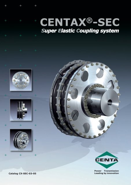
<strong><strong>CENTA</strong>X</strong> ® -SECSuper Elastic Coupling systemCatalog CX-SEC-03-05<strong>Power</strong> <strong>Transmission</strong>Leading by innovation
Company Profile<strong>CENTA</strong> was established in 1970 and since thenhas proved to be the most innovative designer offlexible couplings and shafts for difficult torsionalvibration applications covering industrial and marinedrives worldwide.Today the international <strong>CENTA</strong> group of 10 companiesis one of the worlds leading manufacturersfor advanced power transmission products.Broad Know HowMore than 10 million <strong>CENTA</strong> couplings are installedworldwide thus providing an extraordinarilywide range of application knowledge ranging fromsimple drives to complex multi mass applicationsinvolving complicated torsional vibration calculations.Worldwide ServiceSubsidiary companies in 10 countries, licenseesin 2 and 30 national distributors provide engineeringsupport with local stocks of products andspares close to our customers worldwide.QualityOur QA-system was originally certified to ISO9001 in 1990 by several international inspectionand classification societies. About 65 type approvalshave been granted to <strong>CENTA</strong> products.Headquarters in GermanyTorsional vibration calculation and FEAEngineering with 20 off 3D-CAD work stationsAll new designs are rigorously tested and theirtechnical performance figures precisely measuredin our own development department on a varietyof dynamic test rigs that can induce torques of upto 750 kNm.The complete range of products<strong>CENTA</strong> has 20 different types of flexible coupling,shafts and related products with numerousvariations providing ideal solutions for almostevery application, without the need to compromisesolutions due to product limitations. Theseflexible couplings and shafts cover a broadtorque range, from 10 Nm up to 600.000 Nm andthey are successfully applied in all kind of industries,ship propulsions and auxiliary drives.The next page shows examples of typical applicationsof our main areas of activities: Constructionequipment, agricultural machines, power generation,compressors, train drives, boat and shippropulsion and general machinery.Testbench for 750 kNmFinite Element AnalysisComputer controlled stock for 3700 palletsCX-SEC-4Catalog CX-SEC-01-04
Typical applications of<strong>CENTA</strong> productsTypische Anwendungen von<strong>CENTA</strong> ProdukteCX-SEC-5Catalog CX-SEC-01-04
Successfull <strong><strong>CENTA</strong>X</strong> applicationsErfolgreiche <strong><strong>CENTA</strong>X</strong> EinsatzfälleCX-SEC-6Catalog CX-SEC-01-04
<strong><strong>CENTA</strong>X</strong>-SEC Super Elastic Coupling SystemThis coupling range has been introduced onto themarket in 1988 and has well proved since then inmore than 50000 applications with operating timesup to 80000 hours.Diese Baureihe wurde im Jahr 1988 im Markt eingeführtund sie hat sich seitdem in mehr als 50.000Einsatzfällen mit Einsatzzeiten bis zu 80.000 Stundenhervorragend bewährt.It has been improved continuously and now comprisesthe torque range from 1 up to 440 kNm. Itcan thus be applied for all 4-stroke Diesel enginesin the world market.Sie wurde ständig ausgebaut und umfasst inzwischenden Drehmomentbereich von 1 bis 440 kNm.Damit können praktisch alle 4-Takt Dieselmotorendes Weltmarktes bestückt werden.Important areas of applicationShip´s main and auxiliary drives, Generator sets,Locomotives, Construction machineryWesentliche EinsatzgebieteSchiffs/-haupt und Nebenantriebe, Stromerzeuger,Eisenbahn, Baumaschinen.The componentsThe high elastic <strong><strong>CENTA</strong>X</strong>-coupling range is designedin modular form and is very flexible in itsstructure. It includes the following essential components,which have been developed especially forthis design:-The <strong><strong>CENTA</strong>X</strong>-rubber element, high torsionallyelastic, radially elastic, available in different rubbergrades.-The <strong>CENTA</strong> link coupling or the <strong>CENTA</strong> membranecoupling which are axially and angularly aligning.-A variety of flanges and hubs for standardizeddesigns and for many other interesting specialdesigns.These well-engineered components help to designnumerous coupling designs having the followingpositive characteristics:-High elasticity in all directions: torsional, radial,axial and angular.-High flexibility and ability to adapt in constructionalrespect.-The torsional stiffness can be tuned by differingshore hardness, and/or by arranging the elements-High allowable energy loss because of intensiveventilation of the rubber elements.By clever combination of these components and byadequate arrangement of the <strong><strong>CENTA</strong>X</strong>-elementscoupling designs are created, which show differentfeatures and match the respective applications toan optimum.All designs are also available with fail safe devices.Die KomponentenDas superelastische <strong><strong>CENTA</strong>X</strong>-Kupplungssystem istmodular aufgebaut und konstruktiv äußerst flexibel.Es enthält u.a. folgende wesentliche Bausteine,die speziell für dieses System entwickelt wurden:-Das <strong><strong>CENTA</strong>X</strong>-Gummi-Element, hochdrehelastisch,radial elastisch, in verschiedenen Gummiqualitäten-Die <strong>CENTA</strong>-Lenkerkupplung oder die <strong>CENTA</strong>-Membrankupplung welche in hohem Maße axialund winkelbeweglich sind.-Eine Vielfalt von Flanschen und Naben für Standardbauformenund für viele weitere interessanteSonderbauformen.Mit diesen ausgereiften Bausteinen wird eine Vielzahlvon Kupplungsbauarten konstruiert, die folgendepositive Eigenschaften aufweist:-Hohe Elastizität in allen Richtungen: torsional,radial, axial, winkelig.-Hohe Flexibilität und Anpassungsfähigkeit inkonstruktiver Hinsicht.-Die Drehsteifigkeit kann in weiten Grenzen abgestimmtwerden, durch verschiedene Drehsteifigkeitenund Anordnung der Elemente.-Hohe zulässige Verlustleistung durch intensiveBelüftung der Gummielemente.Somit entstehen durch die geschickte Kombinationdieser Bausteine und durch entsprechende Anordnungder <strong><strong>CENTA</strong>X</strong>-Elemente Kupplungsbaureihenmit verschiedenen, auf die jeweiligen Einsatzfälleoptimal abgestimmten Eigenschaften.Alle Bauformen sind auch mit Durchdrehsicherungverfügbar.CX-SEC-7Catalog CX-SEC-01-04
<strong><strong>CENTA</strong>X</strong> Series N and Gwith membranesizes 35-394torque range 1-440 kNmmit MembraneGrößen 35-394Drehmomentbereich 1-440 kNmRing Elements / Ring ElementeCX-00-NFS CX-00-GSS1 CX-00-GFS2 CX-00-GSS2CX-100-GFS1 CX-100-GSS1 CX-100-GFS2 CX-100-GSS2Segmented Elements / segmentierte ElementeCX-200-GFS1 HUB 200 CX-200-GSS1 HUB 200 CX-200-GFS2 HUB 200 CX-200-GSS2 HUB 200CX-200-GFS1 HUB 260 CX-200-GSS1 HUB 260 CX-200-GFS2 HUB 250 CX-200-GSS2 HUB 250CX-300-GFS1 HUB 200 CX-300-GFF1 CX-300-GFS2 HUB 200 CX-300-GFS2 HUB 250 CX-300-GFF2CX-SEC-10Catalog CX-SEC-01-04
<strong><strong>CENTA</strong>X</strong>with link couplingsizes 52-284torque range 2-110 kNmSeries LRing Elements / Ring Elementemit LenkerkupplungGrößen 52-284Drehmomentbereich 2-110 kNmCX-00-LFS1 CX-00-LSS1 CX-00-LFS2 CX-00-LSS2CX-100-LFS1 CX-100-LSS1 CX-100-LFS2 CX-100-LSS2Segmented Elements / segmentierte ElementeCX-200-LFS1 HUB 200 CX-200-LSS1 HUB 200 CX-200-LFS2 HUB 200 CX-200-LSS2 HUB 200CX-200-LFS1 HUB 250 CX-200-LSS1 HUB 250 CX-200-LFS2 HUB 250 CX-200-LSS2 HUB 250CX-SEC-11Catalog CX-SEC-01-04
The <strong><strong>CENTA</strong>X</strong>flexible elementsConnecting dimensionsDie elastischen<strong><strong>CENTA</strong>X</strong> ElementeAnschlussmasseTraditional sizes with2 digits (Series 00)up to size 75The connecting dimensionshave been kept according thethe SAE-standard J620 withinthe power range up to 25 kNm.For coupling sizes with TkN >25 kNm a new generation ofcoupling elements has been developedwith metric connectingdimensions which diverge fromthe previous dimensions. At thesame time these new couplingdesigns have been developedwith one-piece ring elements(design 100) as well as withsegmented elements (design200 and 300).The bolt pattern on the outsideof the metal flanges of series100, 200, 300 is equal for bothsides. The large bolts providesufficient clamping force for thetransmission of the torque byfriction only. Therefore no fittedbolts are necessary and the assemblyis very easy.As a matter of principle, closedring-elements of design 100should be used wherever it ispossible. The segmented design200 should be applied, ifthere is too little space for theassembly or if a short constructionwith an inner hub is necessary.However, due to reasons of production,because of the weightand the easier assembly it is inevitableto segment the elementsfor the large couplings ofseries 300.The designs of the new flexible<strong><strong>CENTA</strong>X</strong>-elements are presentedon the following pages.Ring elements as hithertowith connecting dimensionsaccording SAE J620traditional sizes with two digitssizes 35 - 75torque range up to 25 kNmRingelemente wie bisher, mitAnschlussmaßen nach SAE J620Baugrößenbezeichnungunverändert mit 2 ZiffernBaugrößen von 35 - 75Drehmomentbereich bis 25 kNmBisherige BaugrößenGrössenbezeichnung mitzwei Ziffern (Serie 00)bis zur Größe 75Im Leistungsbereich bis 25kNm wurden die Anschlussmasseentsprechend der SAE NormJ620 beibehalten. Für die Kupplungsgrößenmit TkN>25 kNmwurde eine neue Generationvon Kupplungselementen entwickelt,welche metrische Anschlussmaßeaufweist, die vonden bisherigen Maßen abweicht.Gleichzeitig wurdendiese neuen Baugrößen sowohlmit ungeteilten Ringelementen(Baureihe 100), als auch mitsegmentierten Elementen(Baureihen 200 und 300) entwickelt.Die äußere Verschraubung derMetallflansche ist bei den Baureihen100, 200, 300 auf beidenSeiten gleich. Diese großenSchrauben erzeugen ausreichendeKlemmkraft für die reibschlüssigeÜbertragung desDrehmoments. Daher sind keinePaßschrauben notwendigund die Montage ist sehr bequem.Grundsätzlich sollten, wo immeres möglich ist, geschlosseneRingelemente der Baureihe100 eingesetzt werden. Diesegmentierte Baureihe 200sollte dann eingesetzt werden,wenn beengte Platzverhältnissebei der Montage vorliegen oderdie Kurzbauform mit einer innenliegenden Nabe notwendigwird.Bei den großen Kupplungen derBaureihe 300 ist es aber ausFertigungsgründen, wegen desGewichts und der besserenMontage, unumgänglich dieElemente zu segmentieren.Folgende Seiten zeigen dieneuen Bauformen der elastischen<strong><strong>CENTA</strong>X</strong>-Elemente.CX-SEC-12Catalog CX-SEC-01-04
<strong><strong>CENTA</strong>X</strong> elementsNew generationsize declaration with three digitsSeries / Baureihe 100<strong><strong>CENTA</strong>X</strong> ElementeNeue GenerationBaugrößenbezeichnungmit drei Ziffernring elements, non segmented,with common metric connecting dimensions.Sizes 176 upto 187.Torque range 25 - 240 kNmRingelemente, nicht segmentiert,mit metrischen marktgängigen AnschlussmaßenBaugrößen von 176 bis 187.Drehmomentbereich:25-240 kNmSeries / Baureihe 200Segmented elements with two segmentsand metric common connectingdimensions.Sizes 276 up to 287.Torque range at the moment :20-200 kNmSegmentierte Elemente mit 2 Segmentenund mit metrischen marktgängigenAnschlußmaßenBaugrößen 276 bis 287.Drehmomentbereich zur Zeit von20 - 200 kNmSeries / Baureihe 300Segmented elements with 3 or 4segments. Common connecting dimensionswith 4 segments.Sizes 391 - 394.Torque range: 160 - 440 kNm.Segmentierte Elemente mit 3 oder4 Segmenten, Anschlussmaßemarktgängig mit 4 Segmenten.Baugrößen von 391 - 394.Drehmomentbereich:160-440 kNmThe new series 100, 200 and 300 have already got type approval from leading socities.CX-SEC-13Catalog CX-SEC-01-04
Description of the ComponentsThe metal parts of the <strong><strong>CENTA</strong>X</strong>-elementsDesign 00, 100 and 200From the beginning, the essential design characteristicsof the <strong><strong>CENTA</strong>X</strong>-elements have been the relativelythin, non-cutting shaped flanges - plain ordished shaped - made of high grade steel.This design of "intelligent lightweight construction"has been realised by <strong>CENTA</strong> for such large couplingsfor the first time in 1988.The equal distribution of stresses and loads withinclosed, one-piece flanges allows for the usage ofrelatively thin sheet metal.These components have been very well proven andthey are characterised by a simple, cheap production,high accuracy and balancing quality, lowweight and low mass moment of inertia.The technology of thin sheet metal has been adaptedand further developed for the new generationof the segmented design 200. Due to being segmented,the flanges are strained and additionallydeformed.The sheet metal parts of the adjacent segments -especially the dished-shaped cranked ones - showthe tendency to move axially in opposition to eachother at the exposed free ends of the cut edge duringthe moment of torsion.Therefore the dished flanges of the <strong><strong>CENTA</strong>X</strong>-segmentsare provided with bars at the inner, non-restraineddiameter, which support the segmentsaxially against each other and thus compensate forbending forces and totally avoid dangerous, unwanteddeformation.Beschreibung der KomponentenDie Metallteile der <strong><strong>CENTA</strong>X</strong>-ElementeBaureihen 00, 100 und 200Das wesentliche konstruktive Kennzeichen der<strong><strong>CENTA</strong>X</strong>-Elemente war von Anfang an die relativdünnen, spanlos geformten Flansche - plan odertellerförmig - aus hochwertigem Stahl.Diese Form des "intelligenten Leichtbaus" wurdevon <strong>CENTA</strong> erstmalig im Jahre 1988 bei derartigengroßen Kupplungen verwirklicht.Die gleichmäßige Spannungsverteilung und Beanspruchungin geschlossenen, nicht segmentiertenFlanschen ermöglicht die Verwendung relativ dünnerBleche.Diese Bauteile haben sich hervorragend bewährtund sie zeichnen sich aus durch einfache, preiswerteHerstellung, hohe Präzision und Wuchtgüte,geringes Gewicht und Massenträgheitsmoment.Bei der neuen Generation der segmentierten Baureihe200 wurde die Technologie der dünnen Blecheübernommen und weiter entwickelt. Durch dasSegmentieren der Flansche, werden diese stärkerbeansprucht und zusätzlich verformt.Die Blechteile von benachbarten Segmenten - insbesonderedie tellerförmig gekröpften - haben unterDrehmoment die Tendenz sich an den freien Endender Schnittflächen axial entgegengesetzt voneinanderzu bewegen.An dieser Stelle werden daher bei den tellerförmigenBlechen der <strong><strong>CENTA</strong>X</strong> Segmente an dem inneren,nicht eingespannten Durchmesser Riegel vorgesehen,die die Segmente axial gegeneinanderabstützen und somit die Biegekräfte kompensierenund die gefährliche und unerwünschte Verformungvöllig verhindern.Distortion of the elements without restraints(exaggerated)Verformung der Segmente ohne Riegel(überhöht)CX-SEC-14Catalog CX-SEC-01-04
Another positive spin-off of this locking and axialstabilization is that the segments are not affectedby any moment of tilt, which would additionallystress the outer bolting (e.g. at the flywheel) as itis most usual for all segmented couplings.This innovative, reasonable locking allows to designreliable segmented couplings with thin metalparts without using additional expensive stabilizingrings for the first time. This idea has been patentedand extensive test series and fatigue tests haveproven their reliability.Ein weiterer positiver Nebeneffekt besteht darin,dass durch diese Verriegelung und axiale Stabilisierungkein Kippmoment auf die Segmente einwirkt,welches die äußere Verschraubung (z.B. zumSchwungrad) zusätzlich beanspruchen würde, wiees bei allen segmentierten Kupplungen ansonstenmeistens der Fall ist.Durch diese innovative, kostengünstige Verriegelungist es erstmalig möglich, segmentierte Kupplungenmit dünnen Metallteilen ohne zusätzlicheteure Stützringe betriebssicher zu gestalten. DieseIdee wurde zum Patent angemeldet, und ausgedehnteVersuchsreihen und Dauertests haben ihreZuverlässigkeit bewiesen.The metal parts of the <strong><strong>CENTA</strong>X</strong> elementsseries 300For the large couplings of the segmented design300, each 2 rubber cross sections have been arrangedin one segment, similar to a two row design.3 or 4 segments each constitute a couplingelement. The middle cast metal part is made of aluminiumwith integral inner cooling air ducts andcooling ribs. Because of this advantageous designand the excellent thermal conductivity of the aluminiumthis middle part operates as a heatexchanger, thus the coupling achieves an extremelyhigh energy loss.Meanwhile, this design has also proved very well inmany applications.Die Metallteile der <strong><strong>CENTA</strong>X</strong>-ElementeBaureihe 300Bei den großen Kupplungen der segmentiertenBaureihe 300 werden je 2 Gummiquerschnitte ineinem Segment angeordnet, ähnlich einer zweireihigenBauform. Je 3 oder 4 Segmente bilden einKupplungselement. Das mittlere Metallteil bestehtaus Aluminium mit eingegossenen inneren Kühlluftkanälenund Kühlrippen. Aufgrund dieser vorteilhaftenGestaltung und der ausgezeichnetenWärmeleitfähigkeit des Aluminiums wirkt diesesMittelteil wie ein Wärmetauscher, daher erzielt dieseKupplung eine außerordentlich hohe Verlustleistung.Auch diese Bauform hat sich inzwischen in der Praxisin vielen Einsatzfällen hervorragend bewährt.The elastomeres of the <strong><strong>CENTA</strong>X</strong>-elementThe flexible element is usually made of high gradenatural rubber; for special applications with hightemperatures it is also available in Silicone.The geometry of the flanges guarantees an equalshear stress through the total cross sectional areawithin the elastomer. Furthermore the peripheralzones are additionally released by generous radiiand rubber outlets.The proportion of the rubber cross section hasbeen optimized regarding high torsional elasticityand high radial elasticity. We have intentionally abstainedfrom openings within the rubber cross section,because this would lead to a weakening of therubber, increased edge stresses would arise and alarger rubber surface would be exposed to aging.An intensive inner and outer ventilation of the couplingnevertheless ensures a high allowable energyloss all the same.Die Elastomere der <strong><strong>CENTA</strong>X</strong>-ElementeDas elastische Element besteht normalerweise aushochwertigem Naturkautschuk oder in Sonderfällenfür hohe Temperaturen aus Silikon.Durch die Geometrie der Flansche ergibt sich imElastomer eine gleiche Schubspannung über dengesamten Querschnitt. Die Randzonen sind zudemdurch großzügige Radien und Gummiausläufe zusätzlichentlastet.Die Proportionen des Gummiquerschnittes wurdenoptimiert in Richtung hohe Drehelastizität undhohe radiale Elastizität. Dabei wurde bewußt aufDurchbrüche und Öffnungen im Gummiquerschnittverzichtet, weil dieser dadurch geschwächt wird,erhöhte Randspannungen entstehen und einegrößere Gummioberfläche der Alterung ausgesetztwird. Durch intensive innere und äußere Ventilationder Kupplungen wird trotzdem eine hohe zulässigeVerlustleistung erzielt.CX-SEC-15Catalog CX-SEC-01-04
The components for axial andradial misalignmentsAs already mentioned, all <strong><strong>CENTA</strong>X</strong>-rubber elementsare torsionally and radially flexible to agreat extent. However, they are relatively stiff inaxial and angular direction. Therefore they arecombined with additional components, which offerthe necessary elasticity in axial and angular direction.<strong>CENTA</strong> has developed 2 different components forthis requirement: membranes and links, whichwill be described in detail as follows.The membranesof the <strong><strong>CENTA</strong>X</strong> series N and GThese membranes are precisely manufacturedfrom high-grade, heat treated spring steel. Large,circular openings reduce their axial and angularstiffness substantially, almost by 50 %.FEM-calculations, extensive test bench runningand proving in practise have shown their reliability.Their spring characteristic in axial direction isalmost linear within the usual range showingslight progression at stronger deformation.These membranes offer a reasonable solution,which allows sufficient misalignment capacity, aswell for engines which are rigidly or elasticallyplaced.With the same membranes flexible shafts havebeen developed and successfully applied underthe name <strong>CENTA</strong>DISC (please see separate catalog).The tube of the middle section can be madefrom steel or preferably from Carbon fibre (CFRP)tube (please also refer to page 18).Die Bausteine für axiale undradiale VerlagerungenWie bereits erwähnt, sind die <strong><strong>CENTA</strong>X</strong>-Gummielementein hohem Maße torsionselastisch und radialelastisch. Sie sind jedoch relativ steif in axialerund angularer Richtung. Daher werden sie mit zusätzlichenBausteinen kombiniert, welche diebenötigte Elastizität in axialer und angularer Richtungbieten.<strong>CENTA</strong> hat für diese Aufgabe 2 verschiedene Bausteineentwickelt: Membranen und Lenkerkupplungen,die nachfolgend detailliert beschriebenwerden.Die Membranender <strong><strong>CENTA</strong>X</strong> Serien N und GDiese Membranen werden präzise aus hochwertigem,wärmebehandelten Federstahl hergestellt.Durch große, kreisrunde Durchbrüche wird ihreaxiale und winkelige Steifigkeit erheblich, fast umdie Hälfte reduziert.Durch FEM Berechnungen, ausgedehnte Prüfstandversucheund Bewährung in der Praxis wurdeihre Betriebssicherheit nachgewiesen. Ihre Federkennliniein axialer Richtung ist im üblicherweisebenutzten Bereich annähernd linear, mitleichter Progression bei stärkerer Verformung.Diese Membranen bieten eine ökonomische Lösung,die für alle gängigen Einsatzfälle ausreichendeVerlagerungsfähigkeit bietet, sowohl fürstarr als auch für elastisch aufgestellte Motore.Mit den gleichen Membranen wurden flexible Gelenkwellenentwickelt und unter dem Namen<strong>CENTA</strong>DISC erfolgreich eingesetzt (siehe separatenKatalog). Die Rohre der Mittelteile werden ausStahl oder vorzugsweise Carbonfaser-Rohren hergestellt(siehe auch Seite 18).CX-SEC-16Catalog CX-SEC-01-04
The link couplingsof the <strong><strong>CENTA</strong>X</strong> series LThe <strong>CENTA</strong> link couplings have already been developedin the year 1992 and since then havebeen proven in thousands of applications. Thisunique, patented design offers higher axial andangular misalignment capacity than any othercomparable system. Their spring stiffness is verylow and shows a linear characteristic.The combination of the torsional and radial flexibilityof the <strong><strong>CENTA</strong>X</strong> element with the axial andangular flexibility of the <strong>CENTA</strong> link coupling offersa coupling system with outstanding advantages.Torsional vibrations, peak loads and considerablemisalignments are compensated for, withoutany wear and with very low reaction forces.These couplings of the <strong><strong>CENTA</strong>X</strong> series L are usedin such cases, when extreme high demands aremade on the misalignment capacity of the couplings,e.g. extremely soft mounted engines in luxuryyachts, catamarans and passenger ships, forshock stress at marine applications for acousticdecoupling between gear and propeller shaft.The <strong><strong>CENTA</strong>X</strong> series L coupling therefore representsthe ultimate idea of the <strong><strong>CENTA</strong>X</strong> Super ElasticCoupling system - SEC.The <strong>CENTA</strong> link coupling is an ingenious combinationof links for push and pull with rubber elasticbushes. Each link has a cylindrical rubber bush,which is bolted radially to the hub and a cardanicrubber joint, which is bolted axially to a flange,both ends using strong bolts. This innovative designoffers a simple, cost efficient and easy way toassemble a link coupling. Depending on couplingsize, 4 to 8 links are used.Die Lenkerkupplungender <strong><strong>CENTA</strong>X</strong> Serie LDie <strong>CENTA</strong> Lenkerkupplungen wurden bereits imJahr 1992 entwickelt und haben sich seitdem inTausenden von Einsatzfällen hervorraged bewährt.Diese einzigartige, patentierte Konstruktionbietet höhere axiale und angulare Verlagerungsfähigkeitals jedes andere vergleichbare System.Ihre Federsteifigkeit ist sehr niedrig undweist eine lineare Kennlinie auf.Die Kombination des dreh- und radialelastischen<strong><strong>CENTA</strong>X</strong>-Elementes mit der axial und angular beweglichen<strong>CENTA</strong>-Lenkerkupplung ergibt Kupplungenmit ganz herausragenden Eigen-schaften.Drehschwingungen, Stöße und insbesondere erheblicheVerlagerungen jeder Art werden ohneVerschleiß, und mit geringen Rückstellkräftenausgeglichen.Diese <strong><strong>CENTA</strong>X</strong> Serie L Kupplungen werden danneingesetzt, wenn außergewöhnlich hohe Anforderungenan die Verlagerungsfähigkeit der Kupplungengestellt werden, z.B. extrem weich gelagerteMotore in Luxusyachten, Katamaranen und Passagierschiffen,für Schockbelastungen bei Marineanwendungenund zur akustischen Entkoppelungzwischen Getriebe und Propellerwelle.Die <strong><strong>CENTA</strong>X</strong>-Baureihe L verkörpert daher in ganzbesonderem Maße die Idee des <strong><strong>CENTA</strong>X</strong>-SuperelastischenKupplungssystems-SEC.Die <strong>CENTA</strong>-Lenkerkupplung besteht aus sinnvollangeordneten, für Zug und Druck ausgelegtenLenkern aus hochfestem, geschmiedeten Aluminiumoder Stahl, mit gummielastischen Buchsen. Injedem Lenker befinden sich eine zylindrischeBuchse, die radial mit der Nabe verschraubt istund eine Kugelbuchse, die axial mit einemFlansch verschraubt ist. Beide Buchsen werdenmit reichlich dimensionierten Schrauben befestigt.Diese neuartige Konstruktion ergibt einesehr einfache, preiswerte gut montierbare Lenkerkupplung.Je nach Kupplungsgröße sind 4 - 8Lenker angeordnet.CX-SEC-17Catalog CX-SEC-01-04
The design of the links for the <strong><strong>CENTA</strong>X</strong>-L-couplingis based on well proven and conservatively selectedrubber bushes where the rubber is vulcanisedto the outer and inner metal part and stands underhigh precompression.This results in link couplings with following advantages:* High axial and angular misalignment capabilitybut torsionally and radially stiff; more than anyother system* Low reaction forces in axial and angular directionswhere reaction forces are proportional tomisalignment* Maintenance-free, no wear* Protected by international patents* Type approved by the leading classification societies* Performing reliably in thousands of applicationssince 1992 in all kinds of ships and in industrialapplications.A double cardanic system results by the arrangementof 2 linksets on an intermediate tube - namelya universal joint shaft - which compensatesfor extreme misalignments. Such <strong>CENTA</strong>LINKu/joints are in successful service in shipbuildingand industrial applications.Please see separate catalog.Die Gummigelenke der <strong><strong>CENTA</strong>X</strong>-L-Kupplung basierenauf bewährten, reichlich dimensioniertenGummibuchsen bzw. Kugelgelenken, wobei dasGummi am inneren und äußeren Metall anvulkanisiertist und unter hoher Druckvorspannung steht.Die <strong>CENTA</strong>-Lenkerkupplungen bieten folgende Eigenschaften:* Hohe axiale und winkelige Verlagerungsfähigkeit,jedoch drehsteif und radial steif; mehrals jedes andere System* Geringe axiale und winkelige Rückstellkräfte,Rückstellkräfte proportional zur Auslenkung* Wartungs- und verschleißfrei* Geschützt durch internationale Patente* Typengenehmigt von den führenden Klassifikationsgesellschaften* Tausende von Kupplungen bewähren sich seit1992 im harten Einsatz in jeder Art von Schiffenund in der Industrie.Durch die Anordnung von 2 Lenkereinheiten aneinem Zwischenrohr entsteht ein doppelkardanischesSystem - eine sogenannte Gelenkwelle - dieextreme Verlagerungen aufnehmen kann. SolcheGelenkwellen werden unter dem Namen<strong>CENTA</strong>LINK erfolgreich im Schiffbau und in der Industrieeingesetzt.Siehe separaten Katalog.<strong>CENTA</strong>DISC with carbon fibre shaft in Jumbocat<strong>CENTA</strong>DISC mit Carbonfaser-Rohr in Jumbocat<strong>CENTA</strong>LINK with carbon fibre shaft in Pacific Titan<strong>CENTA</strong>LINK mit Carbonfaser-Rohr in Pacific Titan<strong>CENTA</strong>DISC in ship propulsion<strong>CENTA</strong>DISC in Schiffsantrieb<strong>CENTA</strong>LINK in JetlinerCX-SEC-18Catalog CX-SEC-01-04
Further <strong><strong>CENTA</strong>X</strong> series<strong><strong>CENTA</strong>X</strong>Series / Baureihe V<strong><strong>CENTA</strong>X</strong> Series V is a torsionally soft intermediatecoupling for universal jointshafts which has proved well over theyears in thousands of applications. Resonancespeeds are shifted below theworking speed range and torsional vibrationswhile going through resonanceare effectively dampened to allowablevalues.Weitere <strong><strong>CENTA</strong>X</strong> BauformenDie <strong><strong>CENTA</strong>X</strong>-Baureihe V hat sich seitmehreren Jahren tausendfach bewährtals drehelastische dämpfende Vorschaltkupplungfür Kardanwellen.Durch die Drehelastizität werden diekritischen Resonanzen auf niedrigeDrehzahlen unterhalb des Betriebsdrehzahlbereichesverlagert undgleichzeitig werden die Drehschwingungen,insbesondere bei der Resonanzdurchfahrt,wirkungsvoll auf zulässigeWerte gedämpft.Nominal torque range:0.2 - 50 kNm.Detailed description and technicaldata are shown in a seperatecatalog CX-V.Nenndrehmomentbereich:0,2 - 50 kNm.Ausführliche Beschreibung undtechnische Daten finden Sie imseparaten Katalog CX-V.<strong><strong>CENTA</strong>X</strong>Series / Baureihe DP<strong><strong>CENTA</strong>X</strong>-series DP uses the high torsionaland radial flexibility of the <strong><strong>CENTA</strong>X</strong>elementfor damping torsional vibrationsand radial misalignments. Due tothe axial stiffness of the element thecoupling is perfectly suitable forsmooth transmission of torque andpropeller thrust.This coupling series dampens torsionalvibrations, compensates the radial misalignmentand noise - noise and vibrationare reduced substantially.An ideal and well proven coupling forcomfortable drives in passenger boatsand fast patrol crafts, specially for flexiblemounted gear or engine/gearunits.Nominal torque range:20 - 480 kNm.Detailed description in seperatecatalog.Die <strong><strong>CENTA</strong>X</strong>-Baureihe DP nutzt diehohe Drehelastizität und die radialeNachgiebigkeit des <strong><strong>CENTA</strong>X</strong>-Elementeszur Drehschwingungsdämpfung undzum Ausgleich von radialen Verlagerungen.Gleichzeitig ist die Kupplungaxial steif und daher bestens geeignetzur elastischen Übertragung des Propellerschubesauf das Getriebe.Die Kupplung dämpft dabei Schwingungen,gleicht Versatz aus und dämpftGeräusche - der Körperschall wird wesentlichreduziert.Eine ideale und bewährte Kupplung fürkomfortable Antriebe von Passagierschiffenund Marineeinheiten, besondersbei elastisch gelagertem Getriebebzw. Motor / Getriebeeinheiten.Nenndrehmomentbereich:20 - 480 kNm.Ausführliche Beschreibung inseparatem Katalog.<strong><strong>CENTA</strong>X</strong>Series / Baureihe TTThe <strong><strong>CENTA</strong>X</strong>-TT series is based on aunique design principle:2 rubber sections, arranged concentrically,acting in parallel and radially precompressed,jointly transmit the torque.This series features high reliability,linear stiffness characteristic on amedium stiffness level and very intensiveinner and outer ventilation.Areas of application: One or two rowseries for gensets or ship propulsion onrigid or stiff mounts. The version with aspacer or shaft and 2 sets of elements,one on each end, provides high flexibilityfor engines on flexible mounts.Nominal torque range:16 - 500 KNmDetailed description in seperateCX-TT catalog.Die Baureihe <strong><strong>CENTA</strong>X</strong>-TT basiert auf einembesonderen Konstruktionsprinzip:2 konzentrisch angeordnete und parallelgeschaltete und radial vorgespanntesegmentierte Gummiquerschnitteübertragen gemeinsam das Drehmoment.Diese Baureihe zeichnet sich durchäußerste Robustheit, lineare Kennliniemit mittlerem Drehsteifigkeitsniveauund intensivierter innerer und äußererVentilation aus.Einsatzgebiete: Stromerzeuger mitstarr oder steif ausgestellten Motorenoder als Schiffshauptantrieb mit elastischerWelle, wobei je ein Satz <strong><strong>CENTA</strong>X</strong>-TT-Elemente an jedem Ende der Welleangeordnet ist für elastisch aufgestellteMotore.Nenndrehmomentbereich:16 - 500 KNmAusführliche Beschreibung in separatemCX-TT Katalog.CX-SEC-19Catalog CX-SEC-01-04
Special TypesSonderbauformen<strong><strong>CENTA</strong>X</strong> coupling with 3, 4 ormore elements - arranged in series- are available in order toincrease the torsional flexibility.<strong><strong>CENTA</strong>X</strong>-Kupplungen mit 3, 4 odermehr Elementen, in Reihe angeordnet,um die Drehelastizität zuerhöhen sind verfügbar.<strong><strong>CENTA</strong>X</strong> Series 200for Tunnel GearThis coupling transmits torquefrom the propeller shaft via atunnelgear to a generator inplants with 2-stroke engines.Sizes: 276 - 287Torque: 20 - 200 kNm<strong><strong>CENTA</strong>X</strong> Serie 200für TunnelgetriebeDiese Kupplung überträgt dasDrehmoment von der Propellerwelleauf ein Tunnelgetriebeund von dort auf einen Generator.Das Tunnelgetriebe istum die Propellerwelle angeordnet.Dieses Prinzip wird bei2-Takt-Motoren vorgesehen.Größen: 276 - 287Drehmoment: 20 - 200 kNm<strong>CENTA</strong> Carbon fibre shaft, combined with flexible <strong><strong>CENTA</strong>X</strong> couplings<strong>CENTA</strong> Karbonfaser Rohr, kombiniert mit elastischen <strong><strong>CENTA</strong>X</strong> Kupplungen<strong><strong>CENTA</strong>X</strong>-coupling, combined with an Airflex clutch.<strong><strong>CENTA</strong>X</strong>-Kupplung, kombiniert mit einer Airflex-Schaltkupplung.<strong><strong>CENTA</strong>X</strong>-coupling, combined with a Wichita clutch.<strong><strong>CENTA</strong>X</strong>-Kupplung, kombiniert mit einer Wichita-Schaltkupplung.CX-SEC-20Catalog CX-SEC-01-04
Examples for series withfail safe deviceBeispiele für Bauformenmit DurchdrehsicherungCX-00-NFSCX-00-GFS2CX-00-LFS1CX-00-LFS2CX-100-GFS1 CX-100-GFS2 CX-100-LFS1 CX-100-LFS2CX-200-GFS1 CX-200-GFS2 CX-200-LFS1 CX-200-LFS2In general all <strong><strong>CENTA</strong>X</strong>-SEC series are available withfail safe device.Grundsätzlich können alle <strong><strong>CENTA</strong>X</strong>-SEC Bauformenmit Durchdrehsicherung geliefert werden.CX-300-GFS1CX-300-GFS2CX-SEC-21Catalog CX-SEC-01-04
VentilationOne of the aims when designing the <strong><strong>CENTA</strong>X</strong> rangewas to ensure that the element was surroundedby as much air flow as possible to dissipatethe heat, generated by the energy loss, and reducethe temperature at the centre of the element.The larger <strong><strong>CENTA</strong>X</strong>-sizes have additional radial airducts inside the rubber for intensive internal ventilation.The following drawings explain the air circulationfor various <strong><strong>CENTA</strong>X</strong>-types:CX-LFS2 Series 00KühlungBei allen Baureihen und Bauformen des <strong><strong>CENTA</strong>X</strong>Programmes wurde darauf geachtet, daß das<strong><strong>CENTA</strong>X</strong>-Element möglichst allseitig von Luft umströmtwird, damit die Verlustleistung gut abgeführtwird, und die Temperatur des Elementesmöglichst niedrig bleibt.Ab der <strong><strong>CENTA</strong>X</strong>-Größe GSF2-391 ist das im Elementeinvulkanisierte Metallteil mit zahlreichenradialen Kanälen versehen, zur intensiven innerenWärmeabfuhr durch Ventilation.Folgende Zeichnungen zeigen beispielhaft denLuftstrom in diversen <strong><strong>CENTA</strong>X</strong>-Bauformen:CX-GFS2 Series 300<strong>CENTA</strong>BUSH with carbon fibre shaft<strong>CENTA</strong>BUSH mit Carbonfaser-Rohr<strong><strong>CENTA</strong>X</strong>-LFS2CX-SEC-22Catalog CX-SEC-01-04
Quality AssuranceClassificationThe comprehensive quality assurance system of<strong>CENTA</strong> Antriebe in accordance with DIN/EN/ISO9001 has been certified by several classificationsocieties.We can supply <strong>CENTA</strong> couplings with survey toEN 10204 and with certificates of classification societies.For the certification by a classification society werequire the following data:- Name of the classification society- Ship owner- Shipyard- Yard number- Main or auxiliary drive- Type of drive- Engine manufacturer and type- <strong>Power</strong>- Speed<strong>CENTA</strong> holds about 65 type approvals from all leadingclassification societies for all important couplingseries including the new series 100, 200 and300.QualitätssicherungKlassifikationDas umfassende Qualitätssicherungsprogrammder Firma <strong>CENTA</strong> Antriebe nach DIN/EN/ISO 9001wurde von mehreren Klassifikationsgesellschaftengeprüft und anerkannt.Wir können <strong>CENTA</strong>-Kupplungen mit Zeugnissennach EN 10204 und mit Abnahme von Klassifikationsgesellschaftenliefern.Für die Abnahme von Schiffskupplungen durcheine Gesellschaft benötigen wir folgende Angaben:- Name der Abnahmegesellschaft- Schiffseigner- Einbauwerft- Bau-Nr. der Werft- Haupt- oder Nebenantrieb- Antriebsart- Motorhersteller und -typ- Leistung- Drehzahl<strong>CENTA</strong> besitzt ca. 65 Typengenehmigungen vonallen führenden Klassifikationsgesellschaften füralle wichtigen Kupplungsbaureihen.Every <strong><strong>CENTA</strong>X</strong> element is indivually inspected and tested100% Inspektion und Prüfung jedes <strong><strong>CENTA</strong>X</strong>-Elementes.Quality control of <strong>CENTA</strong> hubs.Maßprüfung von <strong>CENTA</strong> Naben.CX-SEC-23Catalog CX-SEC-01-04
<strong><strong>CENTA</strong>X</strong> ®Technical DataSeries 00 and 1001 Ring Element, non SegmentedTechnische DatenSerie 00 und 1001 Ring-Element, nicht segmentiertNr.*1 2 3 4 5 6 7 8 9 10 11 12 13 14 15Continu- Dyn. Specific Allowable Relative Allowable Axial Allowable Radial Allowable Max.ous torsional torsional energy damping axial stiffness radial stiffness angular speed<strong><strong>CENTA</strong>X</strong> Shore Nominal Max. vibratory stiffness stiffness loss shaft shaft displace-Size hardness torque torque torque displace- displace- mentat 10 Hz ment mentZul. Dyn. Spezi- Zul. Relative Zul. Axiale Zul. Radiale Zul. Max.Wechsel- Dreh- fische Verlust- Dämp- axialer Feder- radialer Feder- winkelige Drehzahl<strong><strong>CENTA</strong>X</strong> Gummi- Nenn- Max. dreh- steifig- Dreh- leistung fung Wellen- steife Wellen- steife Aus-Größe qualität dreh- Dreh- moment keit steifig- versatz versatz lenkungmoment moment bei 10 Hz keitShore T KNT KmaxT KWC TdynC /T Tdyn KNP KVy K aC KaK rC rdynK wn max)A [kNm] [kNm] [kNm] [kNm/rad] [kW] [mm] [kN/mm] [mm] [kN/mm] [< °] [min -1 ]G L G L G L45 2,25 6,75 0,56 10,20 4,53 0,27 1,00 3,00 0,37 0,5 15250 2,80 8,40 0,70 12,00 4,29 0,28 1,05 ± 5 ± 10 0,22 0,29 3,00 0,4460 3,00 9,00 0,75 15,00 5,00 0,29 1,10 3,00 0,53360070 3,50 10,50 0,88 29,00 8,29 0,30 1,15 1,00 0,9145 2,90 8,70 0,73 13,00 4,48 0,30 1,00 3,00 0,42 0,5 15650 3,50 10,50 0,88 15,40 4,40 0,31 1,05± 5 ± 10 0,28 0,293,00 0,49360060 4,00 12,00 1,00 19,30 4,83 0,33 1,10 3,00 0,5970 4,40 13,20 1,10 36,50 8,30 0,35 1,15 1,00 1,0350 5,50 16,50 1,38 21,20 3,85 0,36 1,05 3,00 1,0064 60 6,00 18,00 1,50 26,30 4,38 0,38 1,10 ± 5 ± 10 0,47 0,36 3,00 1,30 0,5 1 290070 6,50 19,50 1,63 56,00 8,62 0,40 1,15 1,00 2,1050 7,50 22,50 1,88 47,00 6,27 0,46 1,05 4,00 1,366 60 8,25 24,75 2,06 59,00 7,15 0,48 1,10 ± 5 ± 10 0,69 0,43 4,00 1,6 0,5 1 290070 9,00 27,00 2,25 105,00 11,67 0,50 1,15 1,20 2,850 11,00 33,00 2,75 68,00 6,18 0,54 1,05 4,00 1,4069 60 12,00 36,00 3,00 85,00 7,10 0,57 1,10 ± 13 0,53 0,52 4,00 1,80 1 290070 13,00 39,00 3,25 155,00 11,92 0,60 1,15 1,20 3,0050 11,50 34,50 2,88 68,00 5,91 0,54 1,05 4,00 1,5070/71 60 12,50 37,50 3,13 85,00 6,08 0,57 1,10 ± 5 ± 13 0,84 0,52 4,00 1,80 0,5 1 290070 13,00 39,00 3,25 155,00 11,92 0,60 1,15 1,20 3,0050 15,00 45,00 3,75 94,50 6,30 0,61 1,05 5,00 1,8072 60 16,50 49,50 4,13 118,00 6,42 0,64 1,10 ± 6 ± 13 1,00 0,62 5,00 2,20 0,5 1 275070 18,00 54,00 4,50 212,00 11,78 0,67 1,15 1,50 3,8050 20,00 60,00 5,00 135,00 6,75 0,68 1,05 5,50 2,1075 60 22,00 66,00 5,50 169,00 7,15 0,71 1,10 ± 6 ± 13 1,12 0,75 5,50 2,50 0,5 1 230070 25,00 75,00 6,25 305,00 12,20 0,75 1,15 1,70 4,3050 25,00 75,00 6,25 165,00 6,60 0,89 1,05 5,50 3,50176 60 30,00 90,00 7,50 200,00 6,70 0,93 1,10 ± 6 ± 13 1,12 0,75 5,50 4,30 0,5 1 220070 33,00 99,00 8,25 365,00 11,00 0,98 1,15 1,70 7,3050 31,50 94,50 7,90 210,00 6,60 0,97 1,05 6,00 3,90177 60 37,50 112,50 9,40 250,00 6,70 1,01 1,10 ± 6 ± 18 1,20 1,10 6,00 4,70 0,5 1 200070 44,00 132,00 11,00 485,00 11,00 1,06 1,15 2,00 8,0050 40,00 120,00 10,00 264,00 6,60 1,07 1,05 7,00 4,20179 60 48,00 144,00 12,00 320,00 6,70 1,12 1,10 ± 6 ± 18 1,15 1,10 7,00 5,20 0,5 1 187070 55,00 165,00 13,75 605,00 11,00 1,18 1,15 2,50 8,8050 50,00 150,00 12,50 320,00 6,40 1,17 1,05 7,00 4,20181 60 60,00 180,00 15,00 390,00 6,50 1,23 1,10 ± 7 ± 18 1,15 1,10 7,00 5,10 0,5 1 172570 70,00 210,00 17,50 730,00 10,40 1,29 1,15 2,50 8,7050 63,00 189,00 15,75 415,00 6,60 1,28 1,05 7,50 4,80183 60 75,00 225,00 18,75 500,00 6,70 1,34 1,10 ± 7 ± 18 1,18 1,10 7,50 5,80 0,5 1 160070 85,00 255,00 21,25 935,00 11,00 1,41 1,15 2,50 9,9050 80,00 240,00 20,00 522,00 6,53 1,41 1,05 8,00 5,00184 60 95,00 285,00 23,75 627,00 6,55 1,48 1,10 ± 7 ± 18 1,18 1,10 8,00 6,20 0,5 1 150070 110,00 330,00 27,50 1210,00 11,00 1,55 1,15 2,50 10,4050 125,00 375,00 31,25 790,00 6,32 1,69 1,05 8,00 5,70186 60 150,00 450,00 37,50 948,00 6,32 1,77 1,10 ± 9 - 1,20 - 8,00 7,00 0,5 - 110070 180,00 540,00 45,00 1800,00 10,00 1,86 1,15 2,50 11,9050 175,00 525,00 43,75 1155,00 6,60 1,93 1,05 8,00 7,30187 60 210,00 630,00 52,50 1390,00 6,60 2,02 1,10 ± 9 - 1,20 - 8,00 8,90 0,5 - 100070 240,00 720,00 60,00 2640,00 11,00 2,12 1,15 2,50 15,10CX-SEC-24Catalog CX-SEC-01-04
<strong><strong>CENTA</strong>X</strong> ®Technical DataSeries 00 and 1002 Ring Elements, Non Segmentedarranged in seriesTechnische DatenSerie 00 und 1002 Ring-Elemente, nicht segmentiertin Reihe angeordnetNr.*1 2 3 4 5 6 7 8 9 10 11 12 13 14 15Continu- Dyn. Specific Allowable Relative Allowable Axial Allowable Radial Allowable Max.ous torsional torsional energy damping axial stiffness radial stiffness angular speed<strong><strong>CENTA</strong>X</strong> Shore Nominal Max. vibratory stiffness stiffness loss shaft shaft displace-Size hardness torque torque torque displace- displace- mentat 10 Hz ment mentZul. Dyn. Spezi- Zul. Relative Zul. Axiale Zul. Radiale Zul. Max.Wechsel- Dreh- fische Verlust- Dämp- axialer Feder- radialer Feder- winkelige Drehzahl<strong><strong>CENTA</strong>X</strong> Gummi- Nenn- Max. dreh- steifig- Dreh- leistung fung Wellen- steife Wellen- steife Aus-Größe qualität dreh- Dreh- moment keit steifig- versatz versatz lenkungmoment moment bei 10 Hz keitShore T KNT KmaxT KWC TdynC /T Tdyn KNP KVy K aC KaK rC rdynK wn max)A [kNm] [kNm] [kNm] [kNm/rad] [kW] [mm] [kN/mm] [mm] [kN/mm] [< °] [min -1 ]G L G L G L52 45 2,25 6,75 0,56 5,10 2,27 0,54 1,00 6,00 0,19 0,5 150 2,80 8,40 0,70 6,00 2,14 0,56 1,05± 5 ± 10 0,22 0,296,00 0,22275060 3,00 9,00 0,75 7,50 2,50 0,58 1,1 6,00 0,2770 3,50 10,50 0,88 14,50 4,14 0,60 1,15 2,00 0,4556 45 2,90 8,70 0,73 6,50 2,24 0,60 1,00 6,00 0,20 0,5 150 3,50 10,50 0,88 7,70 2,20 0,62 1,05 6,00 0,24± 5 ± 10 0,28 0,2960 4,00 12,00 1,00 9,65 2,41 0,66 1,1 6,00 0,30290070 4,40 13,20 1,10 18,25 4,15 0,70 1,15 2,00 0,5150 5,50 16,50 1,38 10,60 1,93 0,72 1,05 6,00 0,5064 60 6,00 18,00 1,50 13,15 2,09 0,76 1,1 ± 5 ± 10 0,47 0,36 6,00 0,60 0,5 1 290070 6,50 19,50 1,63 28,00 4,08 0,80 1,15 2,00 1,1050 7,50 22,50 1,88 23,50 3,13 0,92 1,05 8,00 0,6066 60 8,25 24,75 2,06 29,50 3,57 0,96 1,1 ± 5 ± 10 0,69 0,43 8,00 0,70 0,5 1 290070 9,00 27,00 2,25 52,50 5,83 1,00 1,15 2,40 1,3050 11,00 33,00 2,75 34,00 3,09 1,08 1,05 8,00 0,7069 60 12,00 36,00 3,00 42,50 3,54 1,14 1,1 ± 5 ± 13 0,84 0,52 8,00 0,90 0,5 1 290070 13,00 39,00 3,25 77,50 5,96 1,20 1,15 2,40 1,5050 11,50 34,50 2,88 34,00 2,96 1,08 1,05 8,00 0,7070/71 60 12,50 37,50 3,13 42,50 3,40 1,14 1,1 ± 5 ± 13 0,84 0,52 8,00 0,90 0,5 1 290070 13,00 39,00 3,25 77,50 5,96 1,20 1,15 2,40 1,5050 15,00 45,00 3,75 47,25 3,15 1,22 1,05 10,00 0,9072 60 16,50 49,50 4,13 59,00 3,58 1,28 1,1 ±6 ± 13 1,00 0,62 10,00 1,10 0,5 1 250070 18,00 54,00 4,50 106,00 5,89 1,34 1,15 3,00 1,9050 20,00 60,00 5,00 67,50 3,38 1,36 1,05 11,00 1,0075 60 22,00 66,00 5,50 84,50 3,84 1,42 1,1 ± 6 ± 13 1,12 0,75 11,00 1,30 0,5 1 220070 25,00 75,00 6,25 152,50 6,10 1,50 1,15 3,40 2,2050 25,00 75,00 6,25 82,50 3,30 1,78 1,05 11,00 1,80176 60 30,00 90,00 7,50 100,00 3,35 1,86 1,1 ± 6 ± 13 1,12 0,75 11,00 2,20 0,5 1 220070 33,00 99,00 8,25 182,50 5,50 1,96 1,15 3,40 3,6050 31,50 94,50 7,90 105,00 3,30 1,94 1,05 12,00 1,90177 60 37,50 112,50 9,40 125,00 3,35 2,02 1,1 ± 6 ± 18 1,20 1,10 12,00 2,40 0,5 1 200070 44,00 132,00 11,00 242,50 5,50 2,12 1,15 4,00 4,0050 40,00 120,00 10,00 132,00 3,30 2,14 1,05 14,00 2,10179 60 48,00 144,00 12,00 160,00 3,35 2,24 1,1 ± 7 ± 18 1,15 1,10 14,00 2,60 0,5 1 187070 55,00 165,00 13,75 302,50 5,50 2,36 1,15 5,00 4,4050 50,00 150,00 12,50 160,00 3,20 2,34 1,05 14,00 2,10181 60 60,00 180,00 15,00 195,00 3,25 2,46 1,1 ± 7 ± 18 1,15 1,10 14,00 2,60 0,5 1 172570 70,00 210,00 17,50 365,00 5,20 2,58 1,15 5,00 4,3050 63,00 189,00 15,75 207,50 3,30 2,56 1,05 15,00 2,40183 60 75,00 225,00 18,75 250,00 3,35 2,68 1,1 ± 7 ± 18 1,18 1,10 15,00 2,90 0,5 1 160070 85,00 255,00 21,25 467,50 5,50 2,82 1,15 5,00 4,9050 80,00 240,00 20,00 261,00 3,27 2,82 1,05 16,00 2,50184 60 95,00 285,00 23,75 313,50 3,28 2,96 1,1 ± 7 ± 18 1,18 1,10 16,00 3,10 0,5 1 150070 110,00 330,00 27,50 605,00 5,50 3,10 1,15 5,00 5,2050 125,00 375,00 31,25 395,00 3,16 3,38 1,05 16,00 2,90186 60 150,00 450,00 37,50 474,00 3,16 3,54 1,1 ± 9 - 1,20 - 16,00 3,50 0,5 - 110070 180,00 540,00 45,00 900,00 5,00 3,72 1,15 5,00 5,9050 175,00 525,00 43,75 577,50 3,30 3,86 1,05 16,00 3,60187 60 210,00 630,00 52,50 695,00 3,30 4,04 1,1 ± 9 - 1,20 - 16,00 4,40 0,5 - 100070 240,00 720,00 60,00 1320,00 5,50 4,24 1,15 5,00 7,50CX-SEC-25Catalog CX-SEC-01-04
<strong><strong>CENTA</strong>X</strong>-NFor the lower torque range from1.1 up to 25 kNm <strong>CENTA</strong> offersthe <strong><strong>CENTA</strong>X</strong> Series N. This couplingis purposely designed forthe connection of high speed Dieselengines on soft mounts withfree standing marine gears.The couplings suit flywheels withSAE dimensions, the output hubsare tailored for the different gearinput shafts. It compensates substantialmisalignment of all kinds.The secondary inertia of the couplingshifts the resonances to lowspeeds.A commercially and technicallyadvantageous design which hasproven successful in hundreds ofapplications.See separate CX-N-catalog.Für den niedrigen Drehmomentbereichvon 1,1 bis 25 kNm bietet<strong>CENTA</strong> die <strong><strong>CENTA</strong>X</strong>-Serie N an.Diese Kupplung ist speziell konstruiertfür die Verbindung vonelastisch gelagerten schnell laufendenDieselmotoren mit freiaufgestellten Marine Getrieben.Die Kupplungen passen an SAE-Schwungräder, die Abtriebsnabensind für die verschiedenen Getriebe-Eingangswellenmaßgeschneidert.Sie kompensieren beträchtlichenVersatz. Das sekundäreTrägheitsmoment verschiebtdie Resonanzen in niedrige Drehzahlbereiche.Eine kommerziell und technischvorteilhafte Konstruktion, die sichin hunderten von Einsätzen bewährthat.Siehe separaten CX-N-Katalog.CX-GFS1-100Series 100Flywheel-Shaft1 Ring Element and MembraneSerie 100Schwungrad-Welle1 Ring-Element und MembranSize Dimensions Moments of inertia, masses and distance centre of gravityGrösse Abmessungen Massenträgheiten, Massen und SchwerpunktabständeT KND Ad[kNm] [js7] D TS-bolt d 6N min-max A B C L S 1S 2J 1J 2m 1m 2m total176 25-33 730 700 16 M14 730 260 90-185 138,5 10 342,0 225 22,5 184,0 2,5 4,4 34,5 104,0 138,5177 31,5-44 790 755 18 M16 790 280 100-200 157,5 10 359,0 235 26,0 199,5 3,5 6,3 41,1 123,7 164,8179 40-55 860 820 20 M18 860 310 110-220 170,5 10 382,0 250 26,0 198,0 5,0 9,4 48,9 161,9 210,8181 50-70 920 880 20 M18 920 330 115-235 187,0 10 433,0 285 30,0 225,0 6,9 13,7 58,0 205,0 263,0183 63-85 995 950 22 M20 995 360 125-255 200,0 10 458,5 300 33,5 237,0 9,5 19,8 68,8 260,0 328,8184 80-110 1070 1025 24 M22 1070 385 135-275 213,0 10 476,5 310 36,5 246,5 13,0 28,2 79,8 313,6 393,4186 125-180 1240 1190 26 M24 1240 448 160-320 238,5 12 579,0 385 43,0 297,5 28,2 54,9 129,7 469,1 598,8187 175-240 1355 1295 30 M27 1355 485 160-345 253,0 12 603,5 400 48,0 310,5 43,2 81,2 166,5 576,2 742,7Also available with fail safe design / Auch mit Durchdrehsicherung lieferbarCX-SEC-26Catalog CX-SEC-02-04
CX-GSS1shaft-shaft1 Ring Element and MembraneWelle-Welle1 Ring-Element und Membranseries / Serie 00sizes/Grössen 50-75series / serie 100sizes/Grössen 176-187Size Dimensions Moments of inertia, masses and distance centre of gravityGrösse Abmessungen Massenträgheiten, Massen und SchwerpunktabständeT KND Ad 1- d 2[kNm] [js7] d 6N 1-N 2min-max A B C F G L 1-L 2S 1S 2J 1J 2m 1m 2m total52 2,25-3 466,7 380 160 45-115 106,5 112 333 97 124 125 99,4 100,9 0,22 0,38 20,2 23,3 43,556 2,9-4 466,7 380 160 45-115 106,5 112 333 97 124 125 100,1 101,6 0,23 0,40 20,5 23,6 44,164 5,5-6,5 466,7 418 165 50-118 116 128 370 105,5 136,5 140 113,0 114,0 0,44 0,69 28,2 28,6 56,866 7,5-9 571,5 477 185 70-130 107 117 388 120,5 150,5 155 120,9 126,0 0,58 1,12 34,8 41,3 76,170 11,5-13 584 540 210 70-150 113,5 134,5 409 117 157,5 160 130,0 128,0 1,10 1,36 49,8 50,2 100,072 15-18 673,1 598 235 85-165 126,5 148,5 457,5 133 176 180 142,5 144,0 1,80 2,61 67,9 73,7 141,675 20-25 733,4 650 235 95-170 141 164 511 148 199 200 170,0 167,5 2,83 4,17 86,7 92,8 179,5176 25-33 730 730 260 90-185 178,5 224,5 577,0 157,5 195 225 199,0 184,0 7,6 4,4 147,6 104,0 251,6177 31,5-44 790 790 280 100-200 202,5 236,5 604,0 167,5 200 235 213,0 199,5 10,9 6,3 175,7 123,7 299,4179 40-55 860 860 310 110-220 220,5 249,5 644,0 182,5 212 250 217,0 198,0 17,1 9,4 236,5 161,9 398,4181 50-70 920 920 330 115-235 237,0 275,0 730,0 208 247 285 244,0 225,0 22,8 13,7 283,9 205,1 489,0183 63-85 995 995 360 125-255 241,0 296,0 773,5 217,5 260 300 258,0 237,0 34,2 19,8 364,0 260,0 624,0184 80-110 1070 1070 385 135-275 268,0 304,0 801,5 227,5 270 310 267,0 246,5 46,8 28,2 429,1 313,6 742,7186 125-180 1240 1240 448 160-320 296,5 334,5 979,0 302,5 342 385 314,5 297,5 90,0 54,2 634,2 469,1 1103,3187 175-240 1355 1355 485 160-345 316,0 364,0 1018,5 302,5 352 400 338,0 310,5 131,5 81,2 772,3 576,2 1348,5CX-SEC-27Catalog CX-SEC-02-04
CX-GFS2Flywheel - Shaft2 Ring Elements and MembraneSchwungrad - Welle2 Ring-Elemente und Membranseries / Serie 00sizes/Grössen 50-75series / Serie 100sizes/Grössen 176-187Size Dimensions Moments of inertia, masses and distance centre of gravityGrösse Abmessungen Massenträgheiten, Massen und SchwerpunktabständeT KN SAE D A dJ[kNm] 620 [js7] D T Z S-bolt d 6 N min-max A B C L S 1 S 2 S 3 J 1 J 2 J 3 m 1 m 2 m 3 m total52 2,25-3 14 466,7 438,2 16x22,5° 13 M12 466,7 160 45-115 188,5 5 291 125 7,4 79,7 110,0 0,16 0,23 0,41 4,9 9,9 25,9 40,756 2,9-4 14 466,7 438,2 16x22,5° 13 M12 466,7 160 45-115 188,5 5 291 125 8,4 79,7 110,4 0,17 0,25 0,43 5,2 10,5 26,2 41,964 5,5-6,5 14 466,7 438,2 16x22,5° 13 M12 466,7 165 50-118 205 6 323,5 140 9,9 87,0 126,0 0,24 0,43 0,56 7,2 20,0 33,9 61,166 7,5-9 18 571,5 542,9 12x30° 17 M16 571,5 185 55-130 186 6 316,5 155 7,8 80,3 139,0 0,47 0,71 1,25 8,4 19,1 48,6 76,169 11-12,5 18 571,5 542,9 6x60° 17 M16 584,0 210 70-150 202 7 340 160 11,1 83,0 141,0 0,57 1,34 1,54 9,1 28,9 59,1 97,171 11,5-13 21 673,1 641,4 24x15° 17 M16 584,0 210 70-150 202 7 339 160 7,6 83,0 141,0 0,97 1,34 1,54 13,7 28,9 59,1 101,772 15-18 21 673,1 641,4 24x15° 17 M16 673,1 235 85-165 223 7 378 180 10,9 96,0 157,0 1,14 2,06 2,88 15,2 35,0 83,6 133,875 20-25 24 733,4 692,2 24x15° 19 M18 733,4 235 95-170 250 10 421 200 13,0 106,5 213,0 2,21 3,56 4,52 25,5 50,8 105,0 181,3176 25-33 - 730 700 32x11,25° 16 M14 730 260 90-185 237,5 10 441,0 225 33,0 103,5 190,0 2,9 4,9 4,5 48,3 60,3 107,6 216,2177 31,5-44 - 790 755 32x11,25° 18 M16 790 280 100-200 263,0 10 464,5 235 40,0 110,5 206,0 4,0 7,0 6,5 58,7 73,5 128,4 260,6179 40-55 - 860 820 32x11,25° 20 M18 860 310 110-220 284,0 10 495,5 250 37,0 117,5 203,5 5,6 10,2 9,7 66,3 91,9 166,1 324,3181 50-70 - 920 880 32x11,25° 19 M18 920 330 115-235 316,0 10 560,0 285 45,5 129,5 228,5 8,2 15,5 13,2 87,5 117,8 203,8 409,1183 63-85 - 995 950 32x11,25° 22 M20 995 360 125-255 337,0 10 593,5 300 49,0 138,5 240,5 10,9 21,7 19,1 97,5 145,0 258,0 500,5184 80-110 - 1070 1025 32x11,25° 24 M22 1070 385 135-275 358,0 10 619,5 310 55,0 145,0 251,0 15,4 29,9 27,3 120,9 168,4 311,4 600,7186 125-180 - 1240 1190 32x11,25° 26 M24 1240 448 160-320 411,0 12 749,5 385 63,0 172,5 303,0 33,0 63,3 52,9 189,8 269,7 467,3 926,8187 175-240 - 1355 1295 32x11,25° 30 M27 1355 485 160-345 436,0 12 784,5 400 65,5 187,5 316,0 47,9 98,3 78,9 223,7 359,7 568,8 1152,2CX-SEC-28Catalog CX-SEC-02-04
CX-GSS2Shaft - Shaft2 Ring Elements and MembraneWelle - Welle2 Ring-Elemente und Membranseries / Serie 00sizes/Grössen 50-75series / Serie 100sizes/Grössen 176-187Size Dimensions Moments of inertia, masses and distance centre of gravityGrösse Abmessungen Massenträgheiten, Massen und SchwerpunktabständeT KND Ad 1- d 2[kNm] [js7] d 6N 1-N 2min-max A B C F G L 1-L 2S 1S 2S 3J 1J 2J 3m 1m 2m 3m total52 2,25-3 466,7 466,7 160 45-115 216 221,5 421 97 102,5 125 103,1 212,0 109,9 0,50 0,23 0,41 24,9 9,9 25,9 60,756 2,9-4 466,7 466,7 160 45-115 216 221,5 421 97 102,5 125 103,8 211,8 110,4 0,51 0,25 0,43 25,2 10,5 26,2 61,964 5,5-6,5 466,7 466,7 165 50-118 225 242 470 105 123 140 119,0 234,0 126,0 0,65 0,43 0,56 32,9 17,4 33,4 83,766 7,5-9 571,5 571,5 185 70-130 213 225 478 120 132 155 131,0 240,1 139,0 1,58 0,71 1,25 48,2 19,1 48,6 115,970 11,5-13 584 584 210 70-150 225 248 508 117 143 160 134,0 257,0 140,0 1,92 1,48 1,48 58,4 32,6 56,6 147,672 15-18 673,1 673,1 235 85-165 256 278 566 133 155 180 149,0 282,0 152,0 3,50 2,46 2,78 83,0 43,0 80,0 206,075 20-25 733,4 733,4 235 95-170 283 308 627 148 171 200 173,0 315,0 181,0 5,52 3,55 4,52 105,3 50,8 104,9 261,0176 25-33 730 730 260 90-185 277,5 323,5 676,0 157,5 195 225 207,0 338,5 190,0 7,9 4,9 4,5 161,5 60,3 107,6 329,4177 31,5-44 790 790 280 100-200 308,0 342,0 309,5 167,5 200 235 222,5 355,5 206,0 11,4 7,0 6,5 193,3 73,5 128,4 395,2179 40-55 860 860 310 110-220 334,0 363,0 757,5 182,5 212 250 225,0 379,5 203,5 17,7 10,2 9,7 254,0 91,9 166,1 512,0181 50-70 920 920 330 115-235 366,0 400,0 857,0 208 247 285 256,0 426,5 228,5 24,2 15,5 13,2 313,5 117,8 203,8 635,1183 63-85 995 995 360 125-255 392,0 431,0 907,5 217,5 260 300 268,0 453,5 240,5 35,6 21,7 19,1 393,0 145,0 258,0 796,0184 80-110 1070 1070 385 135-275 413,0 447,0 944,5 227,5 270 310 280,0 469,0 251,0 49,3 29,9 27,3 470,3 168,4 311,4 950,1186 125-180 1240 1240 448 160-320 469,0 505,0 1149,5 302,5 342 385 340,0 572,5 303,0 94,8 63,3 53,1 694,4 269,7 467,3 1431,4187 175-240 1355 1355 485 160-345 499,0 545,0 1199,5 302,5 352 400 351,0 602,5 316,0 136,2 98,2 78,8 829,2 359,7 568,8 1757,7CX-SEC-29Catalog CX-SEC-02-04
CX-LFS1Flywheel - Shaft1 Ring Element and Link couplingSchwungrad - Welle1 Ring-Element und Lenkerkupplungseries / Serie 00sizes/Grössen 50-75series / Serie 100sizes/Grössen 176-184Size Dimensions Moments of inertia, masses and distance centre of gravityGrösse Abmessungen Massenträgheiten, Massen und SchwerpunktabständeT KNSAE D Ad[kNm] J620 [js7] D TZ S-bolt d 5d 6N min-max A B C E L S 1S 2J 1J 2m 1m 2m total52 2,25-3,5 14 466,7 438,2 16x22,5° 13 M12 383 445 140 45-100 79,0 5 246,0 180 125 7,4 127,0 0,16 1,03 4,9 52,6 57,556 2,9-4,4 14 466,7 438,2 16x22,5° 13 M12 383 445 140 45-100 79,0 5 246,0 180 125 8,4 127,0 0,17 1,03 5,2 52,6 57,864 5,5-6,5 14 466,7 438,2 16x22,5° 13 M12 404 470 154 50-100 87,0 6 270,0 189 140 9,9 136,4 0,24 1,46 7,2 71,6 78,867 6,0-7,2 18 571,5 542,9 12x30° 17 M16 404 470 154 50-100 86,0 5 269,0 188 140 7,3 129,3 0,46 1,48 10,3 71,6 81,966 7,5-9 18 571,5 542,9 12x30° 17 M16 441 575 200 65-135 76,0 6 273,0 177 155 7,8 139,1 0,47 2,93 8,4 102,3 110,769 11,0-13 18 571,5 542,9 6x60° 17 M16 542 545 210 65-150 85,5 7 299,0 220 160 11,1 145,5 0,57 3,76 9,7 123,2 132,971 11,5-13 21 673,1 641,4 24x15° 17 M16 542 545 210 65-150 84,5 6 298,0 219 160 8,6 145,5 0,97 3,77 13,6 123,3 136,972 15,0-18 21 673,1 641,4 24x15° 17 M16 600 604 240 65-160 93,5 7 327,0 228 180 10,9 157,5 1,14 6,29 15,2 175,8 191,075 20,0-25 24 733,4 692,2 24x15° 19 M18 610 675 270 65-180 105,0 10 360,0 241 200 13,0 176,0 2,22 9,62 25,5 228,9 254,4176 25-33 - 730 700 32x11,25° 16 M14 607 730 260 90-185 141,0 10 324,0 227,0 225 12,5 175,0 2,4 9,9 30,9 185,2 216,1177 31,5-44 - 790 755 32x11,25° 18 M16 740 790 280 100-200 155,5 10 353,0 284,0 235 13,5 183,5 3,3 17,8 36,4 264,9 301,3179 40-55 - 860 820 32x11,25° 20 M18 785 860 310 110-220 165,5 10 375,0 292,0 250 14,5 195,5 4,7 27,8 44,7 360,0 404,7181 50-70 - 920 880 32x11,25° 20 M18 785 920 330 115-235 189,0 12 423,5 305,5 285 15,5 227,5 7,4 34,9 59,4 395,8 455,2183 63-85 - 995 950 32x11,25° 22 M20 898 995 360 125-255 192,0 12 445,0 313,5 300 16,5 230,0 10,2 51,2 70,8 505,2 576,0184 80-110 - 1070 1025 32x11,25° 24 M22 933 1070 385 135-275 205,0 12 463,0 321,5 310 17,5 241,0 13,9 63,3 81,7 545,5 627,2CX-SEC-30Catalog CX-SEC-01-04
CX-LSS1Shaft - Shaft1 Ring Element and Link couplingWelle - Welle1 Ring-Element und Lenkerkupplungseries / Serie 00sizes/Grössen 50-75series / Serie 100sizes/Grössen 176-184Size Dimensions Moments of inertia, masses and distance centre of gravityGrösse Abmessungen Massenträgheiten, Massen und SchwerpunktabständeT KND Ad 1- d 2[kNm] [js7] d 5d 6N 1N 2min-max A B C F G L 1-L 2S 1S 2J 1J 2m 1m 2m total52 2,25-3,5 466,7 383 380 160 147 45-105 86 165,5 355 107 123 125 100,1 112,8 0,50 0,45 25,9 28,9 54,856 2,9-4 466,7 383 380 160 147 45-105 86 165,5 355 107 123 125 100,6 113,6 0,51 0,46 26,2 29,2 55,464 5,5-6,5 466,7 404 418 165 176 50-115 96 174,0 393 120,5 137,5 140 98,0 118,0 0,56 0,84 31,8 44,7 76,566 7,5-9 571,5 441 477 185 200 55-130 85 163,5 412,5 135,5 152,5 155 89,1 126,9 1,56 1,20 47,2 57,2 104,470 11,5-13 584 542 540 210 230 70-150 96,5 205,0 441 137 157 160 109,0 136,0 1,68 2,93 59,1 90,9 150,072 15-18 673,1 598 598 235 240 85-165 104,5 214,5 490,5 157 177 180 121,0 154,0 3,01 4,67 86,5 119,0 205,575 20-25 733,4 611 650 235 270 95-170 118 225,5 540,5 172 196 200 143 171 5,15 6,96 107 158 265176 25-33 730 607 730 260 - 90-185 181,0 267,0 561,0 157,5 197 225 195,5 175,0 7,5 9,9 144,4 185,2 329,6177 31,5-44 790 740 790 280 - 100-200 197,5 329,0 600,0 167,5 202 235 183,5 209,0 10,8 17,8 171,5 264,9 436,4179 40-55 860 785 860 310 - 110-220 215,5 342,0 639,0 182,5 214 250 214,0 195,5 16,9 27,8 233,0 360,0 593,0181 50-70 920 785 920 330 - 115-235 242,0 358,5 722,5 208 246 285 242,0 227,5 23,5 34,9 285,7 395,8 681,5183 63-85 995 898 995 360 - 125-255 250,0 371,5 762,0 217,5 259 300 255,5 230,0 35,2 51,2 367,8 505,2 873,0184 80-110 1070 933 1070 385 - 135-275 263,0 379,5 790,0 227,5 269 310 263,0 241,0 45,7 63,3 423,4 545,5 968,9CX-SEC-31Catalog CX-SEC-01-04
CX-LFS2Flywheel - Shaft2 Ring Elements and Link couplingSchwungrad - Welle2 Ring-Elemente und Lenkerkupplungseries / Serie 00sizes/Grössen 50-75series / Serie 100sizes/Grössen 176-184Size Dimensions Moments of inertia, masses and distance centre of gravityGr. Abmessungen Massenträgheiten, Massen und SchwerpunktabständeT KNSAE D Ad[kNm] J620 [js7] D T Z S-bolt d 5 d 6 N min-max A B C E L S 1 S 2 S 3 J 1 J 2 J 3 m 1 m 2 m 3 m total52 2,25-3,5 14 466,7 438,2 16x22,5° 13 M12 383 466,7 147 45-105 168,5 6 282,5 248 125 31,6 90,1 86,7 0,42 0,37 0,45 16,9 10,2 29,8 56,956 3,5-4 14 466,7 438,2 16x22,5° 13 M12 383 466,7 147 45-105 168,5 6 282,5 248 125 31,7 90,1 87,8 0,43 0,39 0,46 17,9 10,5 30,2 58,664 5,5-6,5 14 466,7 438,2 16x22,5° 13 M12 404 466,7 176 50-115 182 6 306 260 140 39,0 107,0 90,5 0,53 0,50 0,61 19,0 13,6 44,7 77,366 7,5-9 18 571,5 542,9 12x30° 17 M16 441 571,5 200 55-130 172 18 314 250,5 155 29,3 95,0 101,0 1,69 1,21 1,23 38,7 21,1 71,0 130,870 11,5-13 21 673,1 641,4 24x15° 17 M16 542 584 230 70-150 192 18 337,5 300,5 160 32,6 107,0 111,0 3,44 1,35 2,93 60,1 21,3 90,9 172,372 15-18 21 673,1 641,4 24x15° 17 M16 598 673,1 240 85-165 210 20 372 320 180 37,6 117,0 121,0 4,23 2,42 4,67 69,4 30,1 119,0 218,575 20-25 24 733,4 692,2 24x15° 19 M18 611 733,4 270 95-170 236 25 417,5 343,5 200 41,6 133,0 145,0 6,68 4,58 6,96 90,4 49,4 158,0 297,8176 25-33 - 730 700 - 16 M14 607 730 260 90-185 240,0 10 326,0 423,0 225 33,0 103,5 175,0 2,9 4,9 9,9 48,3 60,3 185,2 293,8177 31,5-44 - 790 755 - 18 M16 740 790 280 100-200 258,0 10 389,5 458,5 235 40,0 110,5 183,5 4,1 7,0 17,8 58,7 73,5 264,9 397,1179 40-55 - 860 820 - 20 M18 785 860 310 110-220 279,0 10 405,5 488,5 250 37,0 117,5 195,5 5,6 10,2 27,8 66,3 91,9 360,0 518,2181 50-70 - 920 880 - 20 M18 785 920 330 115-235 316,0 10 432,5 550,5 285 45,5 129,5 227,5 8,2 15,5 34,9 87,5 117,8 395,8 601,1183 63-85 - 995 950 - 22 M20 898 995 360 125-255 327,0 10 448,5 580,0 300 49,0 138,5 230,0 10,9 21,7 51,2 97,5 145,0 505,2 747,7184 80-110 - 1070 1025 - 24 M22 933 1070 385 135-275 348,0 10 464,5 606,0 310 55,0 145,0 241,0 15,4 29,9 63,3 120,9 168,4 545,5 834,8CX-SEC-32Catalog CX-SEC-01-04
CX-LSS2Shaft - Shaft2 Ring Elements and Link couplingWelle-Welle2 Ring-Elemente und Lenkerkupplungseries / Serie 00sizes/Grössen 50-75series / Serie 100sizes/Grössen 176-184Size Dimensions Moments of inertia, masses and distance centre of gravityGrösse Abmessungen Massenträgheiten, Massen und SchwerpunktabständeT KND Ad 1- d 2[kNm] [js7] d 5d 6N 1N 2min-max A B C F G L 1-L 2S 1S 2S 3J 1J 2J 3m 1m 2m 3m total52 2,25-3,5 466,7 383 380 160 147 45-105 158 237,5 390 107,0 119,0 125 108,9 197,6 87,2 0,32 0,37 0,45 26,9 10,0 29,8 66,756 2,9-4,4 466,7 383 380 160 147 45-105 158 237,5 390 107,0 119,0 125 109,3 197,6 87,8 0,33 0,39 0,46 27,2 10,5 30,2 67,964 5,5-6,5 466,7 404 418 165 176 50-115 174 252,0 428,5 121,5 130,5 140 106,0 187,0 90,5 0,52 0,50 0,84 37,7 12,1 44,7 94,566 7,5-9 571,5 441 477 185 200 55-130 152 230,5 440,5 134,5 146,5 155 129,7 221,6 106,6 0,72 1,21 1,20 40,4 21,1 57,2 118,770 11,5-13 584 542 540 210 230 70-150 171 279,5 467,5 136,0 151,0 160 118,0 202,0 111,0 1,57 1,35 2,93 69,5 21,3 90,9 181,772 15-18 673,1 598 598 235 240 85-165 187 297,0 517,5 157,0 168,5 180 128,0 227,0 121,0 2,62 2,42 4,67 99,0 30,1 119,0 248,175 20-25 733,4 611 650 235 270 95-170 210 317,5 575,5 172,0 186,0 200 145,0 251,0 139,0 3,52 4,58 6,96 111,0 49,4 158,0 318,4176 25-33 730 607 730 260 260 90-185 280,0 366,0 658,0 157,5 195 225 207,0 338,5 175,0 7,9 4,9 9,9 161,5 60,3 185,2 407,0177 31,5-44 790 740 790 280 280 100-200 303,0 434,5 703,5 167,5 200 235 222,5 355,5 183,5 11,4 7,0 17,8 193,3 73,5 264,9 531,7179 40-55 860 785 860 310 310 110-220 329,0 455,5 750,5 182,5 212 250 225,0 379,5 195,5 17,7 10,2 27,8 254,0 91,9 360,0 705,9181 50-70 920 785 920 330 330 115-235 366,0 482,5 847,5 208 247 285 256,0 426,5 227,5 24,2 15,5 34,9 313,5 117,8 395,8 827,1183 63-85 995 898 995 360 360 125-255 382,0 503,5 895,0 217,5 260 300 268,0 453,5 230,0 35,6 21,7 51,2 393,0 145,0 505,2 1043,2184 80-110 1070 933 1070 385 385 135-275 403,0 519,5 931,0 227,5 270 310 280,0 469,0 241,0 49,3 29,9 63,3 470,3 168,4 545,5 1184,2CX-SEC-33Catalog CX-SEC-01-04
<strong><strong>CENTA</strong>X</strong> ®Technical DataSeries 2001 segmented elementTechnische DatenSerie 2001 segmentiertes ElementNr.*1 2 3 4 5 6 7 8 9 10 11 12 13 14 15Continu- Dyn. Specific Allowable Relative Allowable Axial Allowable Radial Allowable Max.ous torsional torsional energy damping axial stiffness radial stiffness angular speed<strong><strong>CENTA</strong>X</strong> Shore Nominal Max. vibratory stiffness stiffness loss shaft shaft displace-Size hardness torque torque torque displace- displace- mentat 10 Hz ment mentZul. Dyn. Spezi- Zul. Relative Zul. Axiale Zul. Radiale Zul. Max.Wechsel- Dreh- fische Verlust- Dämp- axialer Feder- radialer Feder- winkelige Drehzahl<strong><strong>CENTA</strong>X</strong> Gummi- Nenn- Max. dreh- steifig- Dreh- leistung fung Wellen- steife Wellen- steife Aus-Größe qualität dreh- Dreh- moment keit steifig- versatz versatz lenkungmoment moment bei 10 Hz keitShore T KNT KmaxT KWC TdynC /T Tdyn KNP KVy K aC KaK rC rdynK wn max)A [kNm] [kNm] [kNm] [kNm/rad] [kW] [mm] [kN/mm] [mm] [kN/mm] [< °] [min -1 ]G L G L G L50 20,00 60,00 5,00 148,00 7,40 0,76 1,05 5,50 3,20276 60 24,00 72,00 6,00 182,00 7,58 0,80 1,10 ± 6 ± 13 1,12 0,75 5,50 4,00 0,5 1 180070 28,00 84,00 7,00 325,00 11,60 0,84 1,15 1,70 6,7050 25,00 75,00 6,25 190,00 7,60 0,83 1,05 6,00 3,60277 60 30,00 90,00 7,50 228,00 7,60 0,87 1,10 ± 6 ± 18 1,20 1,10 6,00 4,30 0,5 1 170070 35,00 105,00 8,75 430,00 12,20 0,91 1,15 2,00 7,3050 31,50 94,50 7,90 238,00 7,55 0,91 1,05 7,00 3,90279 60 37,50 112,50 9,40 290,00 7,70 0,95 1,10 ± 6 ± 18 1,15 1,10 7,00 4,80 0,5 1 160070 44,00 132,00 11,00 540,00 12,30 1,00 1,15 2,50 8,1050 40,00 120,00 10,00 290,00 7,25 1,00 1,05 7,00 3,90281 60 48,00 144,00 12,00 355,00 7,36 1,05 1,10 ± 7 ± 18 1,15 1,10 7,00 4,70 0,5 1 145070 55,00 165,00 13,75 648,00 11,90 1,10 1,15 2,50 8,0050 50,00 150,00 12,50 374,00 7,48 1,09 1,05 7,50 4,40283 60 60,00 180,00 15,00 455,00 7,58 1,14 1,10 ± 7 ± 18 1,18 1,10 7,50 5,40 0,5 1 125070 70,00 210,00 17,50 832,00 11,90 1,20 1,15 2,50 9,1050 63,00 189,00 15,80 475,00 7,54 1,20 1,05 8,00 4,60284 60 75,00 225,00 18,80 570,00 7,60 1,26 1,10 ± 7 ± 18 1,18 1,1 8,00 5,70 0,5 1 125070 85,00 255,00 21,30 1078,00 12,70 1,32 1,15 2,50 9,6050 100,00 300,00 25,00 710,00 7,10 1,44 1,05 8,00 5,30286 60 125,00 375,00 31,30 862,00 6,90 1,51 1,10 ± 9 - 1,20 - 8,00 6,50 0,5 - 110070 140,00 420,00 35,00 1600,00 11,40 1,58 1,15 2,50 10,9050 150,00 450,00 37,50 1040,00 6,90 1,70 1,05 8,00 6,70287 60 180,00 540,00 45,00 1265,00 7,00 1,79 1,10 ± 9 - 1,20 - 8,00 8,10 0,5 - 100070 200,00 600,00 50,00 2350,00 11,75 1,87 1,15 2,50 13,90CX-SEC-34Catalog CX-SEC-01-04
<strong><strong>CENTA</strong>X</strong> ®Technical DataSeries 2002 segmented elementsarranged in seriesTechnische DatenSerie 2002 segmentierte Elementein Reihe angeordnetNr.*1 2 3 4 5 6 7 8 9 10 11 12 13 14 15Continu- Dyn. Specific Allowable Relative Allowable Axial Allowable Radial Allowable Max.ous torsional torsional energy damping axial stiffness radial stiffness angular speed<strong><strong>CENTA</strong>X</strong> Shore Nominal Max. vibratory stiffness stiffness loss shaft shaft displace-Size hardness torque torque torque displace- displace- mentat 10 Hz ment mentZul. Dyn. Spezi- Zul. Relative Zul. Axiale Zul. Radiale Zul. Max.Wechsel- Dreh- fische Verlust- Dämp- axialer Feder- radialer Feder- winkelige Drehzahl<strong><strong>CENTA</strong>X</strong> Gummi- Nenn- Max. dreh- steifig- Dreh- leistung fung Wellen- steife Wellen- steife Aus-Größe qualität dreh- Dreh- moment keit steifig- versatz versatz lenkungmoment moment bei 10 Hz keitShore T KNT KmaxT KWC TdynC /T Tdyn KNP KVy K aC KaK rC rdynK wn max)A [kNm] [kNm] [kNm] [kNm/rad] [kW] [mm] [kN/mm] [mm] [kN/mm] [< °] [min -1 ]G L G L G L50 20,00 60,00 5,00 74,00 3,70 1,52 1,05 11,00 1,60276 60 24,00 72,00 6,00 91,00 3,79 1,60 1,10 ± 6 ± 13 1,12 0,75 11,00 2,00 0,5 1 180070 28,00 84,00 7,00 162,50 5,80 1,68 1,15 3,40 3,3050 25,00 75,00 6,25 95,00 3,80 1,66 1,05 12,00 1,80277 60 30,00 90,00 7,50 114,00 3,80 1,74 1,1 ± 6 ± 18 1,20 1,10 12,00 2,20 0,5 1 170070 35,00 105,00 8,75 215,00 6,10 1,82 1,15 4,00 3,7050 31,50 94,50 7,90 119,00 3,78 1,82 1,05 14,00 2,00279 60 37,50 112,50 9,40 145,00 3,85 1,90 1,10 ± 6 ± 18 1,15 1,10 14,00 2,40 0,5 1 160070 44,00 132,00 11,00 270,00 6,15 2,00 1,15 5,00 4,0050 40,00 120,00 10,00 145,00 3,63 2,00 1,05 14,00 1,90281 60 48,00 144,00 12,00 177,50 3,68 2,10 1,10 ± 7 ± 18 1,15 1,10 14,00 2,40 0,5 1 145070 55,00 165,00 13,75 324,00 5,95 2,20 1,15 5,00 4,0050 50,00 150,00 12,50 187,00 3,74 2,18 1,05 15,00 2,20283 60 60,00 180,00 15,00 227,50 3,79 2,28 1,10 ± 7 ± 18 1,18 1,10 15,00 2,70 0,5 1 125070 70,00 210,00 17,50 416,00 5,95 2,40 1,15 5,00 4,5050 63,00 189,00 15,80 237,50 3,77 2,40 1,05 16,00 2,30284 60 75,00 225,00 18,80 285,00 3,80 2,52 1,10 ± 7 ± 18 1,18 1,10 16,00 2,80 0,5 1 125070 85,00 255,00 21,30 539,00 6,35 2,64 1,15 5,00 4,8050 100,00 300,00 25,00 355,00 3,55 2,88 1,05 16,00 2,60286 60 125,00 375,00 31,30 431,00 3,45 3,02 1,10 ± 9 - 1,20 - 16,00 3,20 0,5 - 110070 140,00 420,00 35,00 800,00 5,70 3,16 1,15 5,00 5,5050 150,00 450,00 37,50 520,00 3,45 3,40 1,05 16,00 3,40287 60 180,00 540,00 45,00 632,50 3,50 3,58 1,10 ± 9 - 1,20 - 16,00 4,10 0,5 - 100070 200,00 600,00 50,00 1175,00 5,88 3,74 1,15 5,00 6,90CX-SEC-35Catalog CX-SEC-01-04
CX-GFS1Series 200Flywheel - Shaft1 Segmented Elementand Membraneinner hub 250Serie 200Schwungrad - Welle1 segmentiertes Elementund MembranInnennabe 250Size Dimensions Moments of inertia, masses and distance centre of gravityGrösse Abmessungen Massenträgheiten, Massen und SchwerpunktabständeT KND Ad[kNm] [js7] D TS-bolt d 6N min-max A B C L S 1S 2J 1J 2m 1m 2m total276 20-28 730 700 16 M14 740 260 90-185 143,5 10 223,5 225 11,0 118,5 2,3 6,6 33,1 140,1 173,2277 25-35 790 755 18 M16 800 280 100-200 157,5 10 240,5 235 12,0 121,5 3,2 9,2 39,2 150,1 189,3279 31,5-44 860 820 20 M18 870 310 110-220 170,5 10 256,5 250 12,5 132,5 4,5 13,2 44,6 187,2 231,8281 40-55 920 880 19 M18 930 330 115-235 189,0 12 295,0 285 15,0 154,5 7,5 18,7 65,2 233,8 299,0283 50-70 995 950 22 M20 1005 360 125-255 202,0 12 310,0 300 14,5 159,0 9,8 26,8 73,5 292,0 365,5284 63-85 1070 1025 24 M22 1085 385 135-275 215,0 12 319,0 310 16,0 163,0 14,1 37,7 90,2 352,2 442,4286 100-140 1240 1190 26 M24 1255 448 160-320 240,5 14 393,5 385 19,0 210,0 30,2 71,5 145,5 522,0 667,5287 150-200 1355 1295 30 M27 1370 485 160-345 255,0 14 407,0 400 20,0 216,5 43,3 100,8 175,0 620,3 795,3Also available with fail safe design / Auch mit Durchdrehsicherung lieferbarCX-SEC-36Catalog CX-SEC-02-04
CX-GFS1Series 200Flywheel - Shaft1 Segmented Elementand Membraneouter hub 200Serie 200Schwungrad - Welle1 segmentiertes Elementund MembranAußennabe 200Size Dimensions Moments of inertia, masses and distance centre of gravityGrösse Abmessungen Massenträgheiten, Massen und SchwerpunktabständeT KND Ad[kNm] [js7] D TS-bolt d 6N min-max A B C L S 1S 2J 1J 2m 1m 2m total276 20-28 730 700 16 M14 735 260 90-185 143,5 10 335,0 225 11,0 185,5 2,3 6,5 33,1 139,1 172,2277 25-35 790 755 18 M16 795 280 100-200 157,5 10 359,0 235 12,0 210,0 3,2 9,1 39,2 89,2 128,4279 31,5-44 860 820 20 M18 870 310 110-220 170,5 10 382,0 250 12,5 209,0 4,5 13,2 44,6 187,2 231,8281 40-55 920 880 19 M18 930 330 115-235 189,0 12 433,0 285 15,0 237,0 7,5 18,7 65,2 233,8 299,0283 50-70 995 950 22 M20 1005 360 125-255 202,0 12 458,5 300 14,5 248,0 9,8 26,8 73,5 292,0 365,5284 63-85 1070 1025 24 M22 1080 385 135-275 215,0 12 476,5 310 16,0 259,0 14,1 37,7 90,2 352,2 442,4286 100-140 1240 1190 26 M24 1250 448 160-320 240,5 14 579,0 385 19,0 313,0 30,2 71,5 145,5 522,0 667,5287 150-200 1355 1295 30 M27 1370 485 160-345 255,0 14 603,5 400 20,0 322,0 43,3 100,7 175,0 618,8 793,8Also available with fail safe design / Auch mit Durchdrehsicherung lieferbarCX-SEC-37Catalog CX-SEC-02-04
CX-GFS2Series 200Flywheel - Shaft2 Segmented Elementsand Membraneinner hub 250Serie 200Schwungrad - Welle2 segmentierte Elementeund MembranInnennabe 250Size Dimensions Moments of inertia, masses and distance centre of gravityGrösse Abmessungen Massenträgheiten, Massen und SchwerpunktabständeT KND Ad[kNm] [js7] D TS-bolt d 6N min-max A B C L S 1S 2S 3J 1J 2J 3m 1m 2m 3m total276 20-28 730 700 16 M14 740 260 90-185 242,5 10 260,0 225 22,5 103,5 79,5 2,4 4,7 6,4 33,3 62,9 121,2 217,4277 25-35 790 755 18 M16 800 280 100-200 263,0 10 280,5 235 25,5 110,5 77,5 3,3 6,8 9,1 39,3 77,3 145,3 261,9279 31,5-44 860 820 20 M18 870 310 110-220 284,0 10 296,5 250 25,5 117,5 89,5 4,7 9,8 13,2 46,8 91,6 187,9 326,3281 40-55 920 880 19 M18 930 330 115-235 316,0 10 332,5 285 30,0 129,5 103,0 6,7 15,8 18,7 58,0 129,7 234,7 422,4283 50-70 995 950 22 M20 1005 360 125-255 337,0 10 353,5 300 32,5 138,5 108,0 8,8 20,9 26,8 64,5 147,7 293,0 505,2284 63-85 1070 1025 24 M22 1085 385 135-275 358,0 10 369,5 310 36,2 144,5 109,5 12,7 30,3 37,7 79,1 182,4 353,5 615,0286 100-140 1240 1190 26 M24 1255 448 160-320 411,0 12 424,5 385 43,5 172,5 134,5 27,7 64,0 71,6 129,9 291,4 523,3 944,6287 150-200 1355 1295 30 M27 1370 485 160-345 436,0 12 459,5 400 46,5 187,5 148,0 39,7 93,2 100,8 155,9 355,4 619,7 1131,0CX-SEC-38Catalog CX-SEC-02-04
CX-GFS2Series 200Flywheel - Shaft2 Segmented Elementsand Membraneouter hub 200Serie 200Schwungrad - Welle2 segmentierte Elementeund MembranAußennabe 200Size Dimensions Moments of inertia, masses and distance centre of gravityGrösse Abmessungen Massenträgheiten, Massen und SchwerpunktabständeT KND Ad[kNm] [js7] D TS-bolt d 6N min-max A B C L S 1S 2S 3J 1J 2J 3m 1m 2m 3m total276 20-28 730 700 16 M14 740 260 90-185 242,5 10 434,0 225 22,5 103,5 201,0 2,4 4,7 5,8 33,3 62,9 132,0 228,2277 25-35 790 755 18 M16 800 280 100-200 263,0 10 464,5 235 25,5 110,5 217,0 3,3 6,8 9,3 39,3 77,2 158,8 275,3279 31,5-44 860 820 20 M18 870 310 110-220 284,0 10 495,5 250 25,5 117,5 215,5 4,7 9,8 13,5 46,8 91,6 198,6 337,0281 40-55 920 880 19 M18 930 330 115-235 316,0 10 560,0 285 30,0 129,5 246,0 6,7 15,8 19,1 58,0 129,7 250,2 437,9283 50-70 995 950 22 M20 1005 360 125-255 337,0 10 593,5 300 32,5 138,5 256,5 8,8 20,9 27,4 64,5 147,7 311,0 523,2284 63-85 1070 1025 24 M22 1085 385 135-275 358,0 10 619,5 310 36,5 144,5 267,5 12,7 30,3 38,5 79,1 182,4 374,8 636,3286 100-140 1240 1190 26 M24 1255 448 160-320 411,0 12 749,5 385 43,5 172,5 324,5 27,7 64,0 73,1 129,9 291,4 557,0 978,3287 150-200 1355 1295 30 M27 1370 485 160-345 436,0 12 784,5 400 47,0 187,5 334,5 39,7 93,2 103,0 155,9 355,4 659,7 1171,0CX-SEC-39Catalog CX-SEC-02-04
CX-LFS1Series 200Flywheel - Shaft1 Segmented Elementand Link couplinginner hub 250Schwungrad - Welle1 segmentiertes Elementund LenkerkupplungInnennabe 250Size Dimensions Moments of inertia, masses and distance centre of gravityGr. Abmessungen Massenträgheiten, Massen und SchwerpunktabständeT KND Ad[kNm] [js7] D TS-bolt d 5d 6N min-max A B C E L S 1S 2J 1J 2m 1m 2m total276 20-28 730 700 16 M14 607 730 270 90-185 141,0 10 265,0 227,0 225 11,0 128,5 2,3 9,7 33,1 184,0 217,1277 25-35 790 755 18 M16 740 790 280 100-200 155,5 10 327,0 284,0 235 12,0 162,0 3,2 17,6 39,2 262,5 301,7279 31,5-44 860 820 20 M18 785 860 310 110-220 165,5 10 336,0 292,0 250 12,5 164,0 4,5 27,5 44,6 357,8 402,4281 40-55 920 880 19 M18 785 920 330 115-235 189,0 12 349,5 305,5 285 15,0 171,5 7,5 34,8 65,2 395,8 461,0283 50-70 995 950 22 M20 898 995 360 125-255 192,0 12 359,0 313,5 300 14,5 163,5 9,8 50,5 73,5 501,2 574,7284 63-85 1070 1025 24 M22 933 1070 385 135-275 205,0 12 367,0 321,5 310 16,0 169,0 14,1 63,0 90,2 544,8 635,0CX-LFS1Series 200Flywheel - Shaft1 Segmented Elementand Link couplingouter hub 200Schwungrad - Welle1 segmentiertes Elementund LenkerkupplungAußennabe 250Size Dimensions Moments of inertia, masses and distance centre of gravityGr. Abmessungen Massenträgheiten, Massen und SchwerpunktabständeT KND Ad[kNm] [js7] D TS-bolt d 5d 6N min-max A B C E L S 1S 2J 1J 2m 1m 2m total276 20-28 730 700 16 M14 607 730 260 90-185 141,0 10 324,0 227,0 225 11,0 145,0 2,3 9,7 33,1 184,0 217,1277 25-35 790 755 18 M16 740 790 280 100-200 155,5 10 353,0 284,0 235 12,0 183,0 3,2 17,6 39,2 263,1 302,3279 31,5-44 860 820 20 M18 785 860 310 110-220 165,5 10 375,0 292,0 250 12,5 195,0 4,5 27,5 44,6 357,8 402,4281 40-55 920 880 19 M18 785 920 330 115-235 189,0 10 423,5 305,5 285 15,0 227,5 7,5 34,8 65,2 395,8 461,0283 50-70 995 950 22 M20 898 995 360 125-255 192,0 10 445,0 313,5 300 14,5 229,0 9,8 50,5 73,5 501,2 574,7284 63-85 1070 1025 24 M22 933 1070 385 135-275 205,0 10 463,0 321,5 310 16,0 241,0 14,1 63,0 90,2 544,8 635,0CX-SEC-40Catalog CX-SEC-01-04
CX-LFS2Series 200Flywheel - Shaft2 Segmented Elementsand Link couplinginner hub 250Schwungrad - Welle2 segmentierte Elementeund LenkerkupplungInnennabe 250Size Dimensions Moments of inertia, masses and distance centre of gravityGrösse Abmessungen Massenträgheiten, Massen und SchwerpunktabständeT KN D A d[kNm] [js7] D T S-bolt d 5 d 6 N min-max A B C E L S 1 S 2 S 3 J 1 J 2 J 3 m 1 m 2 m 3 m total276 20-28 730 700 16 M14 607 730 260 90-185 240,0 10 364,0 326,0 225 22,5 103,5 134,0 2,4 4,7 9,8 33,3 62,9 191,2 287,4277 25-35 790 755 18 M16 740 790 280 100-200 258,0 10 432,5 389,5 235 25,5 110,5 167,5 3,3 6,8 17,7 39,3 77,2 272,0 388,5279 31,5-44 860 820 20 M18 785 860 310 110-220 279,0 10 449,5 405,5 250 25,5 117,5 170,5 4,7 9,8 27,8 46,8 91,6 373,2 511,6281 40-55 920 880 19 M18 785 920 330 115-235 316,0 10 476,5 432,5 285 30,0 129,5 179,0 6,7 15,8 35,2 58,0 129,7 413,3 601,0283 50-70 995 950 22 M20 898 995 360 125-255 327,0 10 494,0 448,5 300 32,5 138,5 171,5 8,8 20,9 51,1 64,5 147,7 520,9 733,1284 63-85 1070 1025 24 M22 933 1070 385 135-275 348,0 10 510,0 464,5 310 36,5 144,5 179,0 12,7 30,3 63,9 79,1 182,4 571,0 832,5CX-LFS2Series 200Flywheel - Shaft2 Segmented Elementsand Link couplingouter hub 200Schwungrad - Welle2 segmentierte Elementeund LenkerkupplungAußennabe 200Size Dimensions Moments of inertia, masses and distance centre of gravityGrösse Abmessungen Massenträgheiten, Massen und SchwerpunktabständeT KND Ad[kNm] [js7] D TS-bolt d 5d 6N min-max A B C E L S 1S 2S 3J 1J 2J 3m 1m 2m 3m total276 20-28 730 700 16 M14 607 730 260 90-185 240,0 10 423,0 326,0 225 22,5 103,5 176,0 2,4 4,7 9,9 33,3 62,9 194,0 290,2277 25-35 790 755 18 M16 740 790 280 100-200 258,0 10 458,5 389,5 235 25,5 110,5 187,5 3,3 6,8 17,7 39,3 77,2 272,0 388,5279 31,5-44 860 820 20 M18 785 860 310 110-220 279,0 10 488,5 405,5 250 25,5 117,5 200,0 4,7 9,8 27,8 46,8 91,2 373,2 511,2281 40-55 920 880 19 M18 785 920 330 115-235 316,0 10 550,5 432,5 285 30,0 129,5 233,0 6,7 15,8 35,2 58,0 129,7 413,3 601,0283 50-70 995 950 22 M20 898 995 360 125-255 327,0 10 580,0 448,5 300 32,5 138,5 234,5 8,8 20,9 51,1 64,5 147,7 520,9 733,1284 63-85 1070 1025 24 M22 933 1070 385 135-275 348,0 10 606,0 464,5 310 36,5 144,5 246,5 12,7 30,3 63,9 79,1 182,4 571,0 832,5CX-SEC-41Catalog CX-SEC-01-04
<strong>CENTA</strong> couplings and shafts forall kinds of ships<strong>CENTA</strong> Kupplungen und Wellenfür jede Art von SchiffsantriebCX-SEC-42Catalog CX-SEC-01-04
<strong><strong>CENTA</strong>X</strong> ®Technical DataSeries 300<strong><strong>CENTA</strong>X</strong>-GFS11<strong><strong>CENTA</strong>X</strong>size2 3 4 5 6 7 8 9 10 11 12 13 14 15 16ShorehardnessNominaltorqueMax.torqueContinuousvibratorytorqueat 10 HzDyn.torsionalstiffnessSpecifictorsionalstiffnessAllowableenergylossTechnische DatenSerie 300RelativedampingAllowableaxialshaftdisplacementAxialstiffnessAllowableradialshaftdisplacementRadialstiffnessAllowableangulardisplacementFlangesizeMax.speed<strong><strong>CENTA</strong>X</strong>GrößeGummiqualitätNenndrehmomentMax.DrehmomentZul.Wechseldrehmomentbei 10 HzDyn.DrehsteifigkeitSpezifischeDrehsteifigkeitZulässigeVerlustleistungRelativeDämpfungZul.axialerWellenversatzAxialeFedersteifeZul.radialerWellenversatzRadialeFedersteifeZul.winkeligeAuslenkungFlanschgrößeMax.DrehzahlShore ATKN[kNm]TKmax[kNm]TKW[kNm]CTdyn[kNm/rad]CTdyn/TKNPKV[kW]YKa[mm]CKa[kN/mm]Kr[mm]Crdyn[kN/mm]391 50 160 440 40,0 1200 7,50 1,39 1,05 9,0 5,060 180 495 45,0 1500 8,33 1,45 1,10 12,00 1,20 8,0 6,2 0,25 1460 70070 200 550 50,0 2600 13,00 1,53 1,15 7,0 10,4392 50 200 550 50,0 1600 8,00 1,85 1,05 9,0 6,660 240 660 60,0 2000 8,33 1,95 1,10 12,00 1,20 8,0 8,4 0,25 1460 70070 260 715 65,0 3500 13,46 2,05 1,15 7,0 14,0393 50 260 715 65,0 1950 7,50 1,69 1,05 11,0 7,260 300 825 75,0 2400 8,00 1,78 1,10 14,00 1,30 10,0 8,6 0,25 1685 60070 330 908 82,5 4200 12,73 1,86 1,15 9,0 15,0394 50 350 963 87,5 2600 7,43 2,25 1,05 11,0 9,660 400 1100 100,0 3200 8,00 2,37 1,10 14,00 1,30 10,0 11,8 0,25 1685 60070 440 1210 110,0 5600 12,73 2,48 1,15 9,0 19,2Kw[ °] )>nmax[min -1 ]<strong><strong>CENTA</strong>X</strong>-GFS21 2 3 4 5 6 7 8 9 10 11 12 13 14 15 16<strong><strong>CENTA</strong>X</strong>sizeShorehardnessNominaltorqueMax.torqueContinuousvibratorytorqueat 10 HzDyn.torsionalstiffnessSpecifictorsionalstiffnessAllowableenergylossRelativedampingAllowableaxialshaftdisplacementAxialstiffnessAllowableradialshaftdisplacementRadialstiffnessAllowableangulardisplacementFlangesizeMax.speed<strong><strong>CENTA</strong>X</strong>GrößeGummiqualitätNenndrehmomentMax.DrehmomentZul.Wechseldrehmomentbei 10 HzDyn.DrehsteifigkeitSpezifischeDrehsteifigkeitZulässigeVerlustleistungRelativeDämpfungUZul.axialerWellenversatzAxialeFedersteifeZul.radialerWellenversatzRadialeFedersteifeZul.winkeligeAuslenkungFlanschgrößeMax.DrehzahlShore ATKN[kNm]TKmax[kNm]TKW[kNm]CTdyn[kNm/rad]CTdyn/TKNPKV[kW]YKa[mm]CKa[kN/mm]Kr[mm]Crdyn[kN/mm]50 160 440 40,0 600 3,75 2,77 1,05 18,0 2,5391 60 180 495 45,0 750 4,17 2,90 1,10 12,00 1,20 16,0 3,1 0,25 1460 70070 200 550 50,0 1300 6,50 3,05 1,15 14,0 5,250 200 550 50,0 800 4,00 3,70 1,05 18,0 3,3392 60 240 660 60,0 1000 4,17 3,90 1,10 12,00 1,20 16,0 4,2 0,25 1460 70070 260 715 65,0 1750 6,73 4,10 1,15 14,0 7,050 260 715 65,0 975 3,75 3,38 1,05 22,0 3,6393 60 300 825 75,0 1200 4,00 3,55 1,10 14,00 1,30 20,0 4,3 0,25 1685 60070 330 908 82,5 2100 6,36 3,72 1,15 18,0 7,550 350 963 87,5 1300 3,71 4,50 1,05 22,0 4,8394 60 400 1100 100,0 1600 4,00 4,73 1,10 14,00 1,30 20,0 5,9 0,25 1685 60070 440 1210 110,0 2800 6,36 4,95 1,15 18,0 9,6Kw[ ) °]>nmax[min -1 ]CX-SEC-43Catalog CX-SEC-01-04
CX-GFS2-250Series / Serie 300Size Dimensions Moments of inertia, MassesGröße Abmessungen Massenträgheiten, MassenT KN D A d[kNm] C 1 B d 6 A [js7] D T Z S N L min-max J 1 J 2 J 3 m 1 m 2 m 3 m total s 1 s 2 s 3391 160-200 55,0 63,5 177,2 180,6 261,1 861,9 1303,6 17,0 162,5 229,5565 28,5 1472 398,7 1460 1395 32x11,25° 33 520 480 185-370392 200-260 73,3 83,9 198,0 240,9 338,8 923,0 1502,7 17,0 162,5 232,0393 260-330 103,4 150,2 401,5 255,0 458,0 1396,0 2109,0 16,5 187,0 232,0623 30 1700 472,5 1685 1615 32x11,25° 36 600 520 215-430394 350-440 137,9 198,4 439,9 339,5 593,5 1487,0 2420,0 16,5 187,0 234,0395 400-500 auf Anfrage / on request650 44 1946 506,5 1940 1870 32x11,25° 36 660 545 235-470396 520-650CX-GFS2-251Series / Serie 300with failsafemit DurchdrehsicherungSize Dimensions Moments of inertia, MassesGröße Abmessungen Massenträgheiten, MassenT KN D A d[kNm] C 2 B d 6 A [js7] D T Z S N L min-max J 1 J 2 J 3 m 1 m 2 m 3 m total391 160-200392 200-260393 260-330394 350-440395 400-500396 520-650580 43,5 1472 413,7 1460 1395 32x11,25° 33 520 480 185-370 auf Anfrage / on request638 45 1700 487,5 1685 1615 32x11,25° 36 600 520 215-430 auf Anfrage / on request675 69 1946 531,5 1940 1870 32x11,25° 36 660 545 235-470 auf Anfrage / on requestCX-SEC-44Catalog CX-SEC-01-04
CX-GFS2-200Series / Serie 300Size Dimensions Moments of inertia, MassesGröße Abmessungen Massenträgheiten, MassenT KN D A d[kNm] C B d 6 A [js7] DT Z S N L min-max J 1 J 2 J 3 m 1 m 2 m 3 m total s 1 s 2 s 3391 160-200 55,0 63,5 182,2 180,6 261,1 936,0 1377,7 17,0 162,5 380,0814 28,5 1472 398,7 1460 1395 32x11,25° 32 520 480 185-370392 200-260 73,3 83,9 203,5 240,9 338,8 1002,2 1581,9 17,0 162,5 388,0393 260-330 103,4 150,2 409,1 255,0 458,0 1473,0 2186,0 16,5 187,0 424,3929 30 1700 472,5 1685 1615 32x11,25° 36 600 520 215-430394 350-440 137,9 198,4 447,3 339,5 593,5 1563,0 2496,0 16,5 187,0 432,7395 400-500934 44 1946 506,5 1940 1870 32x11,25° 36 660 545 235-470auf Anfrage / on request396 520-650 auf Anfrage / on requestCX-GFS2-201Series / Serie 300with failsafemit DurchdrehsicherungSize Dimensions Moments of inertia, MassesGröße Abmessungen Massenträgheiten, MassenT KNd[kNm] C 1 B d 6 A D A D T Z S N L min-max J 1 J 2 J 3 m 1 m 2 m 3 m total391 160-200392 200-260393 260-330394 350-440395 400-500396 520-650[js7]829 43,5 1472 413,7 1460 1395 32x11,25° 33 520 480 185-370 auf Anfrage / on request944 45 1700 487,5 1685 1615 32x11,25° 36 600 520 215-430 auf Anfrage / on request959 69 1946 531,5 1940 1870 32x11,25° 36 660 545 235-470 auf Anfrage / on requestCX-SEC-45Catalog CX-SEC-01-04
CX-GFS1-200Series / Serie 300Size Dimensions Moments of inertia, MassesGröße Abmessungen Massenträgheiten, MassenT KN D A d[kNm] C B d 6 A [js7] D T Z S N L min-max J 1 J 2 m 1 m 2 m total S 1 S 2391 160-200392 200-260393 260-330394 350-440395 400-500396 520-650655,70 24,00 1472 242,70 1460 1395 32x11,25° 33 520 480 185-370708,00 26,00 1700 281,50 1685 1615 32x11,25° 36 600 520 215-430717,00 26,00 1946 289,50 1940 1870 32x11,25° 36 660 545 235-47052,3 167,7 171 900 1071 42 36069,7 179,9 227 948 1175 42 35398,4 396,6 241 1417 1658 50 402131,2 425,6 321 1494 1815 50 410Auf Anfrage / on requestCX-GFS1-201Series / Serie 300with failsafemit DurchdrehsicherungSize Dimensions Moments of inertia, MassesGröße Abmessungen Massenträgheiten, MassenT KN D A d[kNm] C B d 6 A [js7] D T Z S N L min-max J 1 J 2 m 1 m 2 m total391 160-200392 200-260393 260-330394 350-440395 400-500396 520-650670,7 39,3 1472 257,4 1460 1395 32x11,25° 33 520 480 185-370 Auf Anfrage / on request723,0 41 1700 292 1685 1615 32x11,25° 36 600 520 215-430 Auf Anfrage / on request742,0 51 1946 339,5 1940 1870 32x11,25° 36 660 545 235-470 Auf Anfrage / on requestCX-SEC-46Catalog CX-SEC-02-04
Bolt PatternsBohrbilder3 segmentssizes 391, 393, 3953 SegmenteGrößen 391, 393, 3954 segmentssizes 392, 394, 3964 SegmenteGrößen 392, 394, 396Size T KNnumber of segments BoltGröße [kNm] Anzahl der Segmente D TS Schraube391 160-200 3392 200-260 4393 260-330 3394 350-440 4395 400-500 3396 530-650 41395 33 M301615 36 M331870 36 M33Containership with CX-393Containerschiff mit CX-393CX-394-D double elementacting in parallel withdouble torqueCX-394-D parallelgeschaltet für doppeltesDrehmomentCX-SEC-47Catalog CX-SEC-01-04
Explanation of the technical data1. Size designationThe size is a spontaneously selected number, whichdesignates the nominal size of the rubber element.Erläuterung der technischen Daten1. BaugrößeDie Größe ist eine freigewählte Ziffer, welche dieNenngröße des Gummielementes bezeichnet.2. Rubber qualityThis figure approximately states the nominal shorehardness of the rubber element in Shore A. The nominalvalue and the effective value may deviatefrom this.3. Nominal torqueThe nominal torque of the coupling is the torquewhich can be transmitted continuously over the entirespeed range, unless other operating conditions(e.g. high temperature or certain tough applications)demand a reduction.The working torque T Lwhich is to be transmittedcontinuously or over a prolonged period, musttherefore be smaller or not more than equal to thenominal torque.PT L= ˘P = power to be transmitted in kW9550 n = number of revolutions per minutenT L= torque to be transmittedT L£ T T KNKN= nominal torque of the coupling. .2. GummiqualitätDiese Ziffer gibt in etwa die nominelle Shorehärtedes Gummielementes in Shore A an. Der Sollwertund der effektive Wert können davon abweichen.3. NenndrehmomentDas Nenndrehmoment der Kupplung ist das Drehmoment,das im gesamten Drehzahlbereich dauerndübertragen werden kann, wenn nicht andere Betriebsbedingungen,(z.B. hohe Umgebungstemperaturoder sonstige harte Bedingungen) eine Reduzierungerfordern.Das von der Kupplung ständig oder über einen längerenZeitraum zu übertragende LastdrehmomentT Lmuß also kleiner oder höchstens gleich demNenndrehmoment sein.PT L= ˘P = zu übertragende Leistung in kW9550 n = Drehzahl pro MinutenT L= zu übertragendes LastdrehmomentT L£ T T KNKN= Nenndrehmoment der Kupplung4. Maximum torqueThis maximum torque T Kmaxof the coupling may occuroccasionally, totally up to 1000 times.For more frequent peaks (e.g. engaging of clutches)T Kmax1is relevant, which may occur up to 50000 times.T Kmax1= 0.5 x T KmaxFor very rare, extraordinary conditions, (e.g. shortcircuit, wrong synchronisation) T Kmax2is allowable.T Kmax2= 1.5 x T KmaxThe maximum range for torsional vibrations frompeak to peak is D T max(e.g. passing through resonances,stop manoevres).D T max= 0.6 x T maxRemark:It is anticipated, that those temporary peak torquesdo not create a substantial temperature rise in theflexible rubber element.Governor hunting is not considered as an acceptableworking condition and it should be avoided.4. MaximaldrehmomentDieses Maximaldrehmoment T Kmaxdarf gelegentlichbei transienten Vorgängen insgesamt bis zu 1.000mal auftreten.Für häufige Momentspitzen (z.B. Schaltvorgänge),die bis zu 50.000 mal auftreten dürfen, gilt T Kmax1T Kmax1= 0.5 x T KmaxFür ganz seltene, abnormale Betriebszustände (z.B.Kurzschluss, Fehlsynchronisation), gilt T Kmax2T Kmax2= 1.5 x T KmaxMaximaler Drehmomentbereich (Amplitude zwischenmaximalem und minimalem Drehmoment;z.B. Resonanzdurchfahrten, Bremsmanöver, etc.),gilt D T maxD T max= 0.6 x T maxAnmerkung:Bei den beschriebenen instationären Vorgängenwird davon ausgegangen, dass keine wesentlichenTemperaturerhöhungen in den elastischen Elementenentstehen.Reglerinstabilitäten gehören nicht zu den zulässigeninstationären Betriebszuständen und sollten vermiedenwerden.CX-SEC-48Catalog CX-SEC-01-04
5. Allowable continuous vibratory torque (acvt)The allowable continuous vibratory torque is theamplitude of the continuously allowable periodic torquefluctuation with a basic load up to the value T KNup to a frequency of 10 Hz, and a maximum ambienttemperature of 30°C.The value for the allowable continuous vibratory torqueis a value for the mechanical strength of therubber element. This value is of course limited and,where relevant, reduced by the ambient temperatureand the effective frequency of the vibratory torque.These influences are nowadays taken into considerationin the calculation of the allowable power loss(section 8) and do not have to be taken into accountin this case.6. Dynamic torsional stiffnessThe dynamic torsional stiffness is the relationship ofthe torque to the torsional angle under dynamicloads.The torsional stiffness is constant in <strong><strong>CENTA</strong>X</strong> couplings,i.e. the characteristics is straight or linear, itdoes not change with the torque.Due to the physical properties of the material rubber,the dynamic torsional stiffness of a coupling iswidely depending on the following influences:a) TemperatureHigher temperature reduces the dynamic torsionalstiffnessb) Frequency of vibrationHigher frequencies increase the dynamic torsionalstiffness. That means, that the dynamic torsionalstiffness is higher than the static stiffness.Typically: C Tdynª 1,3 C stat.c) Amplitude of vibratory torqueHigher amplitudes reduce the dynamic torsionalstiffness, therefore small amplitudes result in higherdynamic stiffness.For <strong><strong>CENTA</strong>X</strong> couplings, the torsional stiffness ismeasured on our own test rigs and specified withthe following marginal conditions:preload:0,5 · T KNvibratory torque: ± 0,25 · T KNfrequency:10 Hzambient temperature: t u= 20°CTolerances in the rubber quality can mean that thedynamic torsional stiffness will deviate by ± 15%from the catalog value.In an ambient temperature of more than 30°C, thetorsional stiffness will decrease.5. Zulässiges DauerwechseldrehmomentDas zulässige Dauerwechseldrehmoment ist die Amplitudeder dauernd zulässigen, periodischen Drehmomentschwankungenbei einer Grundlast bis zumWert T KN, bis zu einer Frequenz von 10 Hz, und biszu einer Umgebungstemperatur von 30°C.Der Wert für das zulässige Dauerwechseldrehmomentist ein Wert für die mechanische Belastbarkeitdes Gummielementes. Dieser Wert wird natürlichdurch die Umgebungstemperatur und die effektiveFrequenz des Wechseldrehmomentes begrenzt undgegebenenfalls reduziert.Diese Einflüsse werden heutzutage bei der Berechnungder zulässigen Verlustleistung (Abschnitt 8)berücksichtigt.6. Dynamische DrehsteifigkeitDie dynamische Drehsteifigkeit ist das Verhältnisvon Drehmoment zu Drehwinkel bei dynamischerBelastung.Bei den <strong><strong>CENTA</strong>X</strong>-Kupplungen ist die Drehsteifigkeitkonstant, d.h. die Kennlinie ist gerade bzw. linear,sie verändert sich nicht mit dem Drehmoment.Durch die physikalischen Eigenschaften des WerkstoffesGummi, ist die dynamische Drehsteifigkeiteiner Kupplung u.a. von folgenden Einflüssen abhängig:a) TemperaturHöhere Temperatur reduziert die Drehsteifigkeitb) Frequenz der SchwingungenHöhere Frequenz steigert die Drehsteifigkeit. Dasbedeutet, daß die dynamische Drehsteifigkeithöher ist als die statische Drehsteifigkeit. Erfahrungswert:C Tdynª 1,3 C stat.c) Amplitude des WechselmomentesHöhere Amplituden reduzieren die Drehsteifigkeit,geringe Amplituten ergeben daher einehöhere Drehsteifigkeit.Für die <strong><strong>CENTA</strong>X</strong>-Kupplungen wird die Drehsteifigkeitauf unseren eigenen Prüfständen gemessen und mitfolgenden Randbedingungen festgelegt:Vorlast:0,5 · T KNWechseldrehmoment: ± 0,25 · T KNFrequenz:10 HzUmgebungstemperatur: t u= 20°CDurch Toleranzen in der Gummiqualität kann die dynamischeDrehsteifigkeit ± 15% von dem Katalogwertabweichen.Bei Umgebungstemperaturen über 30°C nimmt dieDrehsteifigkeit ab.The following then applies:C Tdyn red= C Tdyn · S t3Es gilt:C Tdyn red= C Tdyn · S t3CX-SEC-49Catalog CX-SEC-01-04
In addition to the usual TVA using the nominal valuesfor dynamic torsional stiffness, the selection ofthe coupling should be checked for safety reasonswith the following criteria, due to the above mentionedinfluences.An additional TVA with higher dynamic torsionalstiffness of C Tdyn a= 1,4 x C Tdynshould be made forworking conditions with small vibratory amplitudes.Under working conditions with high power loss, thetemperature in the rubber of the coupling will riseand thereby the dynamic torsional stiffness will bereduced. For this case we recommend a TVA to berun with reduced dynamic torsional stiffnessC Tdyn red= 0,75 xC TdynAt the same time the higher temperature will reducethe relative damping Y (please also refer to item9). Therefore we recommend to also run the TVAwith a reduced dampingY red= 0,7 x YWith these limits for C Tdyn a, C Tdyn redand Y redarealistic check of the coupling selection will be achieved,which will usually result in a coupling with highreliability. The same criteria should be applied whencritically checking the behaviour of the engine governor.1,0Zusätzlich zur üblichen Drehschwingungsberechnungmit den nominellen Werten für die dynamischeDrehsteifigkeit sollte die Auslegung der Kupplungwegen der oben erwähnten Einflüsse zur Sicherheitnoch nach folgenden Kriterien überprüft werden:Bei Betriebszuständen mit geringen Amplituden sollteeine Berechnung mit einer höheren dynamischenDrehsteifigkeit von C Tdyn a= 1,4 x C Tdyndurchgeführtwerden.Bei Betriebszuständen mit hoher Verlustleistungsteigt die Temperatur im Inneren des Gummis anund die dynamische Drehsteifigkeit wird reduziert.In diesem Falle empfehlen wir eine Drehschwingungsberechnungmit einer reduzierten DrehsteifigkeitC Tdyn red= 0,75 xC Tdyndurchzuführen.Gleichzeitig wird bei höheren Temperaturen auch dierelative Dämpfung Y reduziert (siehe auch Punkt 9).Daher empfehlen wir in dieser Berechnung mitC Tdyn redauch eine Y red= 0,7 x Y zu berücksichtigen.Mit diesen Grenzwertbetrachtungen mit C Tdyn a,C Tdyn redand Y redwird eine realistische Überprüfungder Kupplungsauslegung erzielt, die in der Praxis inden meisten Fällen zu hoher Betriebssicherheitführt. Die gleichen Grenzwerte sollten auch bei einerkritischen Berechnung des Reglerverhaltens zugrundegelegtwerden.0,90,80,7S t350° Sh60° Sh70° Sh0,60,530 40 50 60 70 80 90 °C86 104 122 140 158 176 184 °F7. Specific torsional stiffnessC Tdyn/ T KNThis quotient states the relative or specific torsionalstiffness, namely the relationship of the dynamictorsional stiffness to the nominal torque. The smallerthis value, the more torsionally soft, relativelyspeaking, is the coupling. Couplings with valuesfrom 10-30 are described as “torsionally flexible”.Couplings with values smaller than 10 are describedas “torsionally highly flexible”.Using this value, the torsional stiffness of differentcouplings can be compared and the level of torsionalstiffnesses assessed.7. Spezifische DrehsteifigkeitC Tdyn/ T KNDieser Quotient gibt die relative oder spezifischeDrehsteifigkeit, nämlich das Verhältnis von dynamischerDrehsteifigkeit zum Nenndrehmoment, an. Jekleiner dieser Wert ist, um so relativ drehweicher istdie Kupplung. Kupplungen mit Werten von 10-30werden als “drehelastisch”, Kupplungen mit Wertenunter 10 werden als “hochdrehelastisch” bezeichnet.Mit Hilfe dieses Wertes kann man die Drehsteifigkeitverschiedener Kupplungen vergleichen und dasDrehsteifigkeitsniveau beurteilen.CX-SEC-50Catalog CX-SEC-01-04
8. Allowable energy lossDue to torsional vibrations and misalignments,energy is converted into heat by damping in the<strong><strong>CENTA</strong>X</strong> coupling, thus increasing the internal temperatureof the coupling. The allowable power loss isthe amount of damping work which is continuouslyconverted into heat which the coupling can dissipateto the environment without the maximum allowabletemperature of the coupling being exceeded(thermal balance).The allowable power loss depends, among other factors,on the design of the coupling (i.e. rubber volume,surface area, internal ventilation) and in particular,on the temperature gradient in relation to theambient temperature t u.The sum total of power losses from the various dynamicmisalignments (radial and angular) and theperiodic torsional vibrations must be smaller thanthe allowable total power loss PKV of the coupling.8. Zulassige VerlustleistungBei Drehschwingungen und Verlagerungen wirddurch Dämpfung in der <strong><strong>CENTA</strong>X</strong>-Kupplung Energie inWärme umgesetzt. Dadurch erhöht sich die innereTemperatur der Kupplung. Die zulässige Verlustleistungist der Betrag an dauernd in Wärme umgewandelterDämpfungsarbeit, den die Kupplung anihre Umgebung abgeben kann, ohne daß dabei diemaximal zulässige Temperatur der Kupplung überschrittenwird (thermisches Gleichgewicht).Die zulässige Verlustleistung hängt ab u.a. von derKonstruktion der Kupplung (z.B. Gummivolumen,Oberfläche, innere Ventilation) und insbesonderevon dem Temperaturgefälle zur Umgebungstemperaturt u.Die Summe der Verlustleistungen aus den verschiedenendynamischen Verlagerungen (radial und winkelig)und den periodischen Drehschwingungen mußkleiner sein als die zulässige gesamte VerlustleistungP KVder Kupplung.Since significant misalignment should not be anticipatedwith flange mounted units, the power lossthen results only from the various orders of torsionalvibrations. It is calculated by the following formula:10,90,80,70,60,50,4S t40,30,20,1030 40 50 60 70 80 90 °C86 104 122 140 158 176 184 °FDa bei geflanschten Anlagen nicht mit nennenswertemVersatz zu rechnen ist, resultiert die Verlustleistungdann nur aus verschiedenen Ordnungen derDrehschwingungen. Sie wird nach folgender Formelberechnet:P VTWT wiC Tdynyin= power loss due to vibrations= altering torque of the order i (kNm)= dynamic torsional stiffness of thecoupling (kNm/rad)= relative damping= ordinal number= number of revolutions (rpm)P VTW= Verlustleistung aus DrehschwingungenT wi= Wechseldrehmoment der Ordnung i (kNm)C Tdyn = dynamische Drehfedersteifigkeit derKupplung (kNm/rad)Y = verhältnismäßige Dämpfungi = Ordnungszahln = Drehzahl (min -1 )For independently mounted units, it is possible thatfurther power losses occur due to misalignment.P VDKr= power loss due to radial misalignment.This power loss is approximately proportional to theradial misalignment DK r, the speed (rpm) and thedamping Y. Further information on this power loss isavailable on request.P VDW= power loss due to angular misalignment.Bei frei aufgestellten Anlagen können außerdemVerlustleistungen durch Versatz auftreten.P VDKr= Verlustleistung aus radialem Versatz.Diese Verlustleistung ist in etwa proportional demradialen Versatz DK r, der Drehzahl (n) und derDämpfung Y. Angaben über diese Verlustleistunggeben wir auf Anfrage.P VDW= Verlustleistung aus winkeligem Versatz. DieseVerlustleistung ist in etwa proportional dem winkeligenVersatz K rund der Drehzahl. Wenn solcherVersatz durch elastische Verformung im Gummielementaufgenommen wird, muß die entsprechendeVerlustleistung berücksichtigt werden.CX-SEC-51Catalog CX-SEC-01-04
This power loss is approximately proportional to theangular misalignment DK rand the speed (rpm). Ifsuch misalignment is absorbed in the rubber, due toelastic deformation, then the corresponding powerloss must be taken into account.In the couplings described here, the angular misalignmentis mainly absorbed by the Link or Membranecoupling, and the resulting power loss is dissipatedthrough the surface of these parts, thus it doesnot have to be taken into account in the energy balancefor the rubber element.A significant dynamic load due to axial misalignment(axial vibrations) should only occur very rarely, thusit is not considered in this case.However, it would easily be absorbed by the linkcoupling or the membrane.9. Relative DampingThe relative damping is the relationship of the dampingwork to the elastic deformation during a periodof vibration.Bei den hier beschriebenen Kupplungen wird winkeligerVersatz hauptsächlich durch die Membranenund die Lenkerkupplung aufgenommen und die darausresultierende Verlustleistung wird von derenOberfläche abgeleitet, sie muß daher in der Energiebilanzfür das Gummielement nicht berücksichtigtwerden.Eine nennenswerte dynamische Belastung durchaxialen Versatz (axiale Schwingungen) durfte sehrselten auftreten und wird hier nicht berücksichtigt,wurde jedoch von den Membranen/Lenkerkupplungenabsorbiert.9. Relative DämpfungDie relative Dämpfung ist das Verhaltnis der Dämpfungsarbeitzur elastischen Formänderungsarbeitwährend einer Schwingungsperiode.Je größer der Wert Y ist, desto geringer ist die Erhöhungdes Wechseldrehmomentes in oder nahe derResonanz. Für den Resonanzfaktor V R(Vergrösserungsfaktor)gilt die vereinfachte Formel:Durch höhere Temperaturen wird die relative Dämpfungreduziert, entsprechend nebenstehendem Diagramm.Y red= Y . S t5Durch Toleranzen in der Gummiqualität kann die relativeDämpfung ±20% von dem Katalogwert abweichen.The larger this value Y is, the smaller is the increaseof the continuous vibratory torque in or near theresonance. For the resonance factor V R(magnificationfactor), the simplified formula will apply:MisalignmentWellenversatzThe relative damping factor is decreased by highertemperature in accordance with the following diagram.Y red= Y . S t5Tolerances in the rubber quality can mean that therelative damping will deviate by ±20% from the catalogvalue.10,90,80,70,6S t550° Sh60° Sh70° Sh0,530 40 50 60 70 80 90 C°86 104 122 140 158 176 194 F°If there is a combinationof the different kinds ofmisalignment, then themax. allowable value forthe individual misalignmenthas to be reduced.Please consult us.Wenn eine Kombinationder verschiedenen Wellenversatzartenvorliegt,dann muß der max. zul.Wert der einzelnen Versatzartenreduziert werden.Lassen Sie sich indiesem Falle bitte von unsberaten.CX-SEC-52Catalog CX-SEC-01-04
10. Axial shaft misalignmentThe coupling is allowed to deviate from this middleposition by the specified amount in both directions.Such axial misalignment can result fromheat expansion, installation faults, foundationchanges and shaft displacement. Furthermore theaxial length of the rubber element changes itselfslightly: it is shortened by the centrifugal forceand it is elongated by the torque. If the sum totalof the axial misalignment and the internal changeof length to be anticipated in any direction, isgreater than the permissible value and the axialmisalignment in the opposite direction is correspondinglysmaller, then this situation can becompensated for, at the time of installation by recalculatingthe initial installation position.11. Axial reaction forces11.1 Type CX-G with membraneWhen the coupling is installed in the middle position,the membrane system is free of axial reactionforces.Due to the almost linear characteristics of themembrane, the calculated reaction force is proportionalto the axial misalignment. The data forthe reaction force are shown in the relevant technicaltable.11.2 Type CX-L with link couplingWhen the coupling is installed in the middle position,the link system is free of axial reaction forces.Due to the linear characteristic of the link coupling,the calculated reaction force is proportionalto the axial misalignment. The data for the reactionforce are shown in the relevant technical tables.F AX= DW A. cK aThis calculated reaction force is only applicableimmediately after installation. Rubber tends tohave a permanent set, so after 3 days the force isdecreased by about 20%.The axial reaction force will furthermore be reducedby about 10% due to temperature increase.Important: It must be checked, whether the bearingsof the shafts are able to bear the axial reactingforces.10. Axialer WellenversatzBei der axialen Baulänge der Kupplungen laut Katalogmaßergibt sich für die Lenkerkupplung bzw.Membranen in axialer Richtung eine mittlere Position.Von dieser Mittellage darf sie um den angegebenenBetrag in beiden axialen Richtungen abweichen.Solche axialen Verlagerungen ergebensich z.B. aus Wärmedehnungen, Einbaufehlern,Fundamentveränderungen und Wellenverschiebungen.Weiterhin ändert sich die axiale Längedes Gummielementes geringfügig in sich selbst:durch Zentrifugalkraft wird es verkürzt und durchDrehmoment verlängert. Wenn die Summe der zuerwartenden axialen Verlagerungen und der internenLängenänderung in einer Richtung größer istals der zulässige Wert, und die axialen Verlagerungenin der entgegengesetzten Richtung dementsprechendgeringer, kann diesem Zustanddurch eine aus der Mittellage entsprechend versetzteaxiale Einbaulage Rechnung getragen werden.11. Axiale Reaktionskräfte11.1 Baureihe CX-G mit MembraneIn der mittleren Position ist das Membran-Systemfrei von axialen Reaktionskräften.Da die Membranen eine annähernd lineare axialeKennlinie aufweisen, ergibt sich bei Axialversatzeine proportionale axiale Reaktionskraft. Angabenhierzu finden Sie in den technischen Daten.11.2 Bauform CX-L mit LenkerkupplungIn der mittleren Position ist das Lenker-Systemfrei von axialen Reaktionskräften.Da die Gummilager der Lenker eine lineare Verdrehkennliniehaben, ergibt sich bei Axialversatzeine proportionale axiale Reaktionskraft. Angabenhierzu finden Sie in den technischen Daten.F AX= DW A. cK aDie danach berechnete axiale Reaktionskraft ergibtsich unmittelbar nach der Verlagerung. DaGummi sich jedoch unter Belastung immer setzt,verringert sich diese ursprüngliche axiale Kraft.So reduziert sich nach einer axialen Verlagerungz.B. innerhalb von 3 Tagen die axiale Reaktionskraftum 20%.Außerdem wird die axiale Reaktionskraft durchTemperaturerhöhung nochmals um ca. 10% reduziert.Wichtig: Es muß geprüft werden, ob die Lagerder verbundenen Wellen die axialen Reaktionskräfteertragen können.CX-SEC-53Catalog CX-SEC-01-04
12. Allowable radial shaft misalignmentThis value specifies the maximum radial misalignmentthat is permissible on a continuous basis.However, such a misalignment produces a powerloss in the coupling (see point 8) and reaction forces(see point 13), which have an effect on the adjacentbearings.For these reasons, the actual radial misalignmentshould be kept as low as possible.The specified value for the permissible radial shaftmisalignment relates to a speed of 600 rpm. Forother speeds, the speed (rpm) factor should beused in accordance with the following diagram.DW r£ DK r◊ S nThe actual shaft misalignment may occasionallyand briefly rise to double the value of the continuouslypermissible shaft misalignment, e.g. duringstarting or shut down of flexibly mounted engines,or in heavy seas, etc.12. Zulässiger radialer WellenversatzDieser Wert gibt den Versatz an, der dauerndhöchstens zulässig ist. Solcher Versatz erzeugt jedochin der Kupplung Verlustleistung (siehe Punkt8) und Reaktionskräfte (siehe Punkt 13), die aufdie benachbarten Lagerstellen einwirken.Aus diesen Gründen sollte der tatsächliche radialeVersatz so gering wie möglich gehalten werden.Der angegebene Wert für den zulässigen radialenWellenversatz bezieht sich auf die Drehzahl von600 min -1 .Für andere Drehzahlen ist der Drehzahlfaktor nachnebenstehendem Diagramm einzusetzen.DW r£ DK r◊ S nDer tatsächliche Wellenversatz darf gelegentlichund kurzzeitig auf den doppelten Wert des dauerndzulässigen Wellenversatzes ansteigen, z.B.beim An- oder Abstellen von elastisch gelagertenMaschinen, starkem Seegang usw.S n1,00,90,80,70,60,50,40 500 1000 1500 2000 2500 3000min -1Here the speed factor does not have to be takeninto account.DW r max= 2 ◊ DK rHowever for the 2 element series with failsafe device:DW r max= 1 ◊ DK r13. Radial reaction forceWhen radial misalignment of the coupling occurs,a radial reaction force F rresults.Dabei muß der Drehzahlfaktor nicht berucksichtigtwerden.DW r max= 2 ◊ DK rBei Baureihen mit 2 Elementen und Durchdrehsicherunggilt jedoch: DW r max= 1 ◊ DK r13. Radiale ReaktionskraftBei radialer Verlagerung der Wellen ergibt sich ausder Kupplung eine radiale Reaktionskraft F r.F r= C r dyn◊ DW rThe value C r dynapplies to rotating shafts and for acoupling temperature of 50° C.At higher temperatures the radial stiffness is alsoreduced according to the temperature factor S t3,as shown in the diagram on page 50.F r red= C r dyn◊ DW r◊ S t3Important:If there is significant radial misalignment, a checkshould be made to ensure that the bearings of thecoupled shafts can withstand the radial reactionforces of the couplings.F r= C r dyn◊ DW rDer Wert C r dyngilt für rotierende Wellen und für eineKupplungstemperatur von 50° C.Bei höheren Temperaturen reduziert sich die radialeSteifigkeit entsprechend dem Temperaturfaktor S t3gemäß Diagramm auf Seite 50.F r red= C r dyn◊ DW r◊ S t3Falls beträchtlicher radialer Versatz vorliegt, ist zuprüfen, ob die Lagerungen der gekuppelten Wellendie radiale Reaktionskraft der Kupplung ertragenkönnen.Wichtig: Es muß geprüft werden, ob die Lagerungder angeschlossenen Bauteile fur die auftretendenaxialen und radialen Reaktionskräfte ausreichend dimensioniertsind.CX-SEC-54Catalog CX-SEC-01-04
14. Angular misalignment14.1 Type CX-G with membraneThe max. allowable angular misalignmentDW W= 0.5 degrees which equals 0.0087 radian or8.8 mm/m.However, in order to achieve a long lifetime, werecommend to keep this value lower, as low aspossible.14.2 Type CX-L with Link couplingFor all sizes the maximum allowable angular misalignmentDW wis 1.0 degrees which equals0.0176 radian or 17.6 mm/m.The continuous allowable value is 0.5 degreeswhich is 50%, but in order to achieve a long lifetimefor the rubber bearings the angular misalignmentshould be kept to the minimum that is reasonable.15. Maximum Speed n max(rpm)This maximum speed n maxis the absolutely highestallowable speed for short time, e.g. duringoverspeed of the motor. The continuously allowablespeed is n cont£ 0,85 ◊ n max14. Winkeliger Versatz14.1 Bauform CX-G mit MembraneDer maximal zulässige winkelige Versatz DW Wbeträgt0,5 Grad, entsprechend 0,0087 rad bzw. 8,8mm/m.Im Interesse einer langen Lebensdauer ist jedochein niedrigerer Wert, so niedrig wie möglich, anzustreben.14.2 Bauform CX-L mit Lenker-KupplungDer maximal zulässige winkelige Versatz DW wbeträgtfür alle Größen 1,0 Grad, entsprechend0,0176 rad bzw. 17,6 mm/m.Der dauernd zulässige Wert beträgt 50% davon,d.h. 0,5 Grad, jedoch ist im Interesse einer langenLebensdauer der Gummilager ein möglichst geringerwinkeliger Versatz anzustreben.15. Maximale Drehzahl n max(min -1 )Diese Drehzahl n maxist die kurzzeitig zulässigehöchste Drehzahl, z.B. bei Überdrehzahl des Motors.Die dauernd zulässige Drehzahl istn cont£ 0,85 ◊ n max16. Storage of <strong><strong>CENTA</strong>X</strong> elementsShould rubber elements be stored during the constructiontime, or as spare parts over a longer period,the following has to be considered:* storage in dry, dark rooms with as little thermalfluctuation as possibleThe following has to be avoided:* direct influence of sun and artificial light sourceswith UV share* storage near to Ozone producing electrical orother equipment* sprinkling with oils, fat, greases, fuels, anaerobicadhesives and chemicals16. Lagerung von <strong><strong>CENTA</strong>X</strong> GummielementenWenn Gummielemente während der Bauphaseoder als Ersatzteil über längere Zeit gelagert werden,dann sind folgende Bedingungen zu beachten:*Lagerung in trockenen, möglichst dunklen Räumenmit möglichst geringen Temperaturschwankungen.Unbedingt vermieden werden muß:***Direkte Sonneneinstrahlung oder künstlicheLichtquellen mit UV-AnteilLagerung in der Nähe von Ozon erzeugendenelektrischen oder sonstigen GerätenBenetzung mit Ölen, Fetten, Schmierstoffen,Brennstoffen, anaeroben Klebstoffen und ChemikalienCX-SEC-55Catalog CX-SEC-01-04
The elements have to be stored in horizontal position,never standing upright. The elements maybe stocked.Die Elemente müssen immer liegend gelagert werden,niemals stehend. Es dürfen mehrere Elementeliegend aufeinander gestapelt werden.17. Protection of the rubber surface againstharmful environmental influencesShould the elements be subject to harmful environmentalinfluences (i.e. intensive supply of ozoniferousair, sprinkling with fuels etc.) they can becoated by a flexible polymer film on the surface.This coating is applied by a paint-brush and canbe touched up or renewed when necessary.This surface protection is also recommended forspare elements, which have to be stored for a longerperiod of time.17. Schutz der Gummioberfläche gegen schädlicheUmwelteinflüsseWenn die Gummielemente durch schädliche Umwelteinflüssegefährdet sind (z.B. intensive Zufuhrvon ozonhaltiger Frischluft, Spritzer von Brennstoffetc.) dann können sie mit einem elastischenSchutzfilm aus synthetischem Gummi an denOberflächen geschützt werden. Diese Schutzfilmwird wie Farbe mit einem Pinsel aufgetragen. DerSchutzanstrich kann nötigenfalls von Zeit zu Zeitausgebessert bzw. erneuert werden.Dieser Oberflächenschutz ist auch ratsam für Ersatzelemente,die über einen längeren Zeitraumgelagert werden.CX-SEC-56Catalog CX-SEC-01-04
NotesNotizenCX-SEC-57Catalog CX-SEC-01-04
<strong>CENTA</strong> Australia<strong>CENTA</strong> Netherland<strong>CENTA</strong> Denmark<strong>CENTA</strong> Headquarters Germany<strong>CENTA</strong> Norway<strong>CENTA</strong> Italy <strong>CENTA</strong> Great Britain <strong>CENTA</strong> Singapore<strong>CENTA</strong>SubsidiariesAustralia<strong>CENTA</strong> <strong>Transmission</strong>s Pty. Ltd.P.O. Box 6245South Windsor, NSW 2756AustriaHainzl Industriesysteme GmbHIndustriezeile 56A-4040 LinzBelgiumCaldic Techniek Belgium N.V.Tollaan 73B-1932 Sint-Stevens-WoluweBrazil<strong>CENTA</strong> Transmissoes Ltda.Rua Josè AméricoCançado Bahia 199Cidade Industrial32.210-130 Contagem MGCanada<strong>CENTA</strong> CORP.815 Blackhawk DriveWestmont, IL 60559, USAChileComercial TGC Ltda.Calle Dr. M. Barros Borgoño 255-263Casilla 16.800 (P.O. Box)Santiago-ProvidenciaChina<strong>CENTA</strong> Representative OfficeRoom.11C, Cross Region PlazaNo. 899 LingLing RoadShanghai, PC200030Denmark<strong>CENTA</strong> <strong>Transmission</strong>er A/SA.C. Illums Vej 5DK-8600 SilkeborgEgyptHydraulic MisrP.O. Box 418Tenth of Ramadan CityFinlandMovetec OyHannuksentie 1FIN-02270 EPOOFrancePrud’Homme<strong>Transmission</strong>s66 Rue des St. DenisB.P. 73F-93302 Aubervilliers CedexGermany<strong>CENTA</strong> AntriebeKirschey GmbHBergische Str. 7D-42781 HaanGreat Britain<strong>CENTA</strong> <strong>Transmission</strong>s Ltd.Thackley Court,Thackley Old Road,Shipley, Bradford,West Yorkshire, BD18 1BWGreeceIndustry: Marine:Kitko S.A. Technava S.A.1, Rodon St. 6,Loudovikou Sq.17121 N.Smymi 18531 PiraeusAthensHong Kong/ChinaFoilborn Enterprise Ltd.Unit A8-9, 13/FVeristrong Industrial Centre34-36 Au Pui Wan StreetFotan, ShatinN.T. Hong KongIndiaNENCONational Engineering CompanyJ-225, M.I.D.C., Bhosari,Pune - 411 026IsraelRedco Equipment & Industry3, Rival StreetTel Aviv 67778IL - Tel AvivItaly<strong>CENTA</strong> <strong>Transmission</strong>i SrlViale A. De Gasperi, 17/19I-20020 Lainate (Mi)JapanMiki Pulley Co.Ltd.1-39-7, KomatsubaraZama-City, KanagawaJAPAN 228-857KoreaMarine Equipment Korea Co. Ltd.#823, Ocean Tower760-3 Woo 1 DongHaeundae-Gu, BusanMexico<strong>CENTA</strong> CORP.815 Blackhawk DriveWestmont, IL 60559, USANetherlands<strong>CENTA</strong> Nederland b.V.Nijverheidsweg 4NL-3251 LP StellendamNew ZealandBrevini Ltd.9 Bishop Croke PlaceEast TamakiPO Box 58-418 - GreenmountNZ-AucklandNorway<strong>CENTA</strong> transmisjoner A.S.P.O.B. 1551N-3206 SandefjordPolandIndustry:Marine:IOW Trade FBSMSp.z.o.o.Engineering & Co.ul. Zwolenska 17 UL.Podmokla 304-761 Warszawa 71-776 SzczecinPortugalPINHOL Import Dep.Avenida 24 de Julho, 174P - LISBOA 1350<strong>CENTA</strong> USAthe international serviceSingapore<strong>CENTA</strong> TRANSMISSIONSFAR EAST PTE LTD51 Bukit Batok Crescent#05-24 Unity CentreSingapore 658077South AfricaEntramarc (PTY) Ltd.P.O. Box 691892021 BryanstonZA - TransvaalSpainHerrekor S.A.Zamoka LantegialdeaOialume Bidea 25, Barrio ErgobiaES-20116 Astigarraga-Gipuzkoa<strong>Sweden</strong><strong>CENTA</strong> <strong>Transmission</strong> <strong>Sweden</strong> ABMetalgatan 21AS-26272 ÄngelholmSwitzerlandHydratec, Hydraulic+Antriebs-Technik AGChamerstrasse 172CH-6300 ZugTaiwanACE Pillar Trading Co., Ltd.No. 2 Lane 61, Sec. 1.Kuanfu Road, San-Chung City, R.O.C.TaipeiTurkeyIndustry:Erler Makina ve Gida Sanayi Ltd.Sti.IvedikOrganize SanayiHas Emek Sitesi 676. Sokak No. 3Ostim/AnkaraUSA<strong>CENTA</strong> CORP.815 Blackhawk DriveWestmont, IL 60559<strong>CENTA</strong> Antriebe is alsorepresented in:Bulgaria, CSFR, Hungaria, Jugoslavia,Romania and further countries.D-42755 Haan P.O.B 11 25tel.: ++49-2129-912-0e-mail: centa@centa.deBergische Strasse 7Fax: ++49-2129-2790http://www.centa.de