MONTAGEANWEISUNG
MONTAGEANWEISUNG
MONTAGEANWEISUNG

Erfolgreiche ePaper selbst erstellen
Machen Sie aus Ihren PDF Publikationen ein blätterbares Flipbook mit unserer einzigartigen Google optimierten e-Paper Software.
erreicht, um Deponien und die Umwelt zu<br />
entlasten. Damit leisten wir gemeinsam einen<br />
wichtigen Beitrag zum Umweltschutz.<br />
RECYCLING VON ALTGERÄTEN<br />
Geräte mit diesem Aufkleber dürfen<br />
nicht mit dem normalen Hausmüll<br />
entsorgt werden. Sie müssen<br />
getrennt gesammelt und gemäß den<br />
lokalen Vorschriften entsorgt werden.<br />
TECHNISCHE DATEN<br />
Spannung .................... 230 V AC ± 10%, 50 Hz<br />
Max. Vorsicherung ....................................... 16 A<br />
Eingebauter Schalter ..................... 2-polig, 16 A<br />
Ausgangsrelais ...... Schließkontakt - SPST - NO<br />
Ausgang ............................. Max. 16 A / 3600 W<br />
Regelprinzip ........................................... PBM/PI<br />
Bereitschaftsbetrieb ................................. 0,6 W<br />
Batterie-Backup ..................................... 5 Jahre<br />
Temperaturbereich ............................. +5/+40 °C<br />
Begrenzungsfühler (OCD4) ................. +5/+40 °C<br />
Umgebungsbetriebstemperatur ......... +0/+25 °C<br />
Energie auslesung, genauigkeit ................... 2%<br />
Verschmutzungsgradkontrolle .......................... 2<br />
Nennimpulsspannung ................................. 4 kV<br />
Schutzgrad .................................................. IP21<br />
Abmessungen .................. H/84, B/84, T/40 mm<br />
Einbautiefe ............................................... 20 mm<br />
Display ................................... 100x64 Pixel STN<br />
- Hintergrundbeleuchtung<br />
EU Gebrauchsmuster ........... 001101349-0001/2<br />
Der Thermostat ist wartungsfrei.<br />
2<br />
English<br />
The thermostat is an electronic on/off thermostat<br />
for temperature control by means of an<br />
NTC sensor located either externally or internally<br />
within the thermostat.<br />
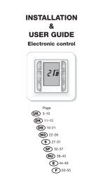
The thermostat is for flush mounting in a wall<br />
socket. A baseplate for external wall mounting<br />
is available.<br />
PRODUCT PROGRAMME<br />
FRTD 903<br />
(MCD4-1999) Clock-thermostat with 2 sensors.<br />
Floor sensor and built-in room<br />
sensor.<br />
WARNING – Important Safety Instructions.<br />
Disconnect the power supply before carrying<br />
out any installation or maintenance work on this<br />
control unit and associated components. This<br />
control unit and associated components should<br />
only be installed by a competent person (i.e. a<br />
qualified electrician). Electrical installation must<br />
be in accordance with appropriate statutory<br />
regulations.<br />
MOUNTING OF SENSOR<br />
The floor sensor contains a safety extra-low<br />
voltage (SELV) circuit, allowing it to be placed<br />
as close to the floor surface as necessary without<br />
having to take account of the risk of shock<br />
should the sensor cable become damaged. The<br />
two wires from the sensor to the mounting box,<br />
must be additionally insulated, e.g. shrink flex.<br />
To prevent loose cables from the fixed installation<br />
from coming into contact with the<br />
terminal block for the floor sensor, they must be<br />
restrained using cable ties.<br />
It is recommended that the cable and sensor be<br />
placed in a non-conductive installation pipe embedded<br />
in the floor (fig. 3). The end of the pipe<br />
must be sealed and the pipe placed as high as<br />
possible in the concrete layer. Alternatively, the<br />
sensor can be embedded directly in the floor.<br />
The sensor cable must be led through a separate<br />
pipe or segregated from power cables.<br />
The floor sensor must be centred between the<br />
heating cable.<br />
The sensor cable may be extended up to 7 m<br />
by means of a separate two-core cable. Two<br />
vacant wires in a multi-core cable used, for<br />
example, to supply current to the floor heating<br />
cable must not be used. The switching peaks<br />
of such current supply lines may create interference<br />
signals that prevent optimum controller<br />
function. If a shielded cable is used, the shield<br />
must not be connected to earth (PE). The twocore<br />
cable must be placed in a separate pipe or<br />
segregated from power cables.<br />
MOUNTING OF THERMOSTAT<br />
WITH BUILT-IN SENSOR<br />
The room sensor is used for comfort temperature<br />
regulation in rooms. The thermostat should<br />
be mounted on the wall approx. 1.6 m above<br />
the floor in such a way as to allow free air circulation<br />
around it. Draughts and direct sunlight or<br />
other heat sources must be avoided (fig. 4). No<br />
external sensor is connected.<br />
Mounting of thermostat<br />
1. Slide the power button down to Off “0”.<br />
2. Release the front cover ONLY by inserting a<br />
small screwdriver into the hole on either side<br />
of the thermostat.<br />
3. Connect the wires in accordance with the<br />
diagram (fig. 2).<br />
4. Mount the thermostat in the wall socket.<br />
5. Fit the frame and carefully press the cover<br />
onto the thermostat. Ensure that both the<br />
power slide button on the cover and the<br />
power switch pin are down.<br />
DO NOT open the thermostat by releasing the<br />
four fixing clips on the back.<br />
First time settings:<br />
The first time the thermostat is connected,<br />
push the power slide button to On “I”. Language,<br />
time and date must be set using the<br />
buttons:<br />
1. Set language<br />
2. Set time<br />
3. Set date<br />
PROGRAMMING<br />
See user manual.<br />
FAULT LOCATION<br />
If the sensor is disconnected or short-circuited,<br />
the heating system is switched off. The sensor<br />
can be checked against the resistance table<br />
(fig. 5).<br />
ERROR CODES<br />
E0: Internal error. The thermostat must be<br />
replaced.<br />
E1: Built-in sensor short-circuited or<br />
disconnected.<br />
E2: External sensor short-circuited or<br />
disconnected.<br />
E5: Internal overheating. Inspect the installation.<br />
CE MARKING<br />
According to the following standard:<br />
LVD/EMC: EN 60730-2-9<br />
CLASSIFICATION<br />
The product is a Class II device (enhanced<br />
insulation) and must be connected to in the<br />
following way:<br />
Term. 1: Neutral (N<br />
Term. 2: Phase (L) 230 V ±10%, 50/60 Hz<br />
Term. 3–4: Load, max. 16 A / 3600 W<br />
Term. X: Do not connect<br />
Term. 5-6: External floor sensor<br />
ENVIRONMENT AND RECYCLING<br />
Please help us to protect the environment by<br />
disposing of the packaging in accordance with<br />
national regulations for waste processing.<br />
© 2010 OJ Electronics A/S - EHT Haustechnik GMBH<br />
RECYCLING OF OBSOLETE APPLIANCES<br />
Appliances with this label must not<br />
be disposed of with general<br />
household waste. They must be<br />
collected separately and disposed<br />
of in compliance with local<br />
regulations.<br />
TECHNICAL DATA<br />
Voltage ............................ 230 VAC ±10% 50 Hz<br />
Max. pre-fuse .............................................. 16 A<br />
Built-in circuit breaker .................... 2-pole, 16 A<br />
Output relay ............. Make contact - SPST - NO<br />
Output ................................ Max. 16 A / 3600 W<br />
Control principle .................................... PWM/PI<br />
Stand-by power ........................................ 0.6 W<br />
Battery backup ....................................... 5 years<br />
Temperature range .............................. +5/+40°C<br />
Limit sensor (OCD4) ............................ +5/+40°C<br />
Ambient operating temperature .......... +0/+25°C<br />
Control pollution degree ................................... 2<br />
Rated impulse voltage ................................. 4 kV<br />
Enclosure rating .......................................... IP 21<br />
Dimensions ...................... H/84, W/84, D/40 mm<br />
Build-in depth .......................................... 20 mm<br />
Display ........ 100x64 pixel STN - white backlight<br />
EU Registered Design ........ 001101349-0001/2<br />
The thermostat is maintenance free.<br />
Español<br />
El termostato de encendido y apagado es<br />
electrónico y controla la temperatura por medio<br />
de un sensor NTC ubicado en el exterior o en el<br />
interior del termostato.<br />
El termostato es para montaje a ras en un<br />
receptáculo de pared. Se dispone de una placa<br />
de base para el montaje mural externo.<br />
PROGRAMA DE PRODUCTOS<br />
FRTD 903<br />
(MCD4-1999) Termostato horario y dos sensores.<br />
Sensor de piso y sensor<br />
incorporado de temperatura<br />
ambiente.<br />
ADVERTENCIA – Instrucciones de seguridad<br />
importantes. Desconecte la fuente de alimentación<br />
eléctrica antes de realizar cualquier<br />
instalación o trabajo de mantenimiento en esta<br />
unidad de control y componentes relacionados.<br />
Solamente una persona competente (por<br />
ejemplo, un electricista cualificado) deberá<br />
instalar esta unidad de control y componentes<br />
relacionados. La instalación eléctrica debe realizarse<br />
de acuerdo con las directivas estatutarias<br />
apropiadas.<br />
MONTAJE DEL SENSOR<br />
El sensor de piso contiene un circuito de seguridad<br />
de voltaje extra bajo (SELV, por su sigla en<br />
inglés), que le permite ser colocado tan cerca<br />
de la superficie del piso como sea necesario<br />
sin tener que tomar en cuenta riesgo alguno de<br />
electrocución si el cable del sensor se dañase.<br />
Además, es preciso aislar con material termoencogible<br />
(p.ej. Shrink Flex) los dos alambres<br />
que van del sensor a la caja de montaje.<br />
Para impedir que los cables sueltos de la<br />
instalación fija entren en contacto con el bloque<br />
de terminales para el sensor de piso, será necesario<br />
sujetar dichos cables con amarras.<br />
Se recomienda colocar el cable y el sensor en<br />
un tubo de instalación no conductivo incrustado<br />
en el piso (fig. 3). Es preciso sellar el extremo<br />
del tubo y colocarlo en la posición más alta<br />
posible en la capa de hormigón. De manera<br />
alternativa, el sensor se puede incrustar directamente<br />
en el piso. Es preciso que el cable del<br />
sensor se pase a través de un tubo separado