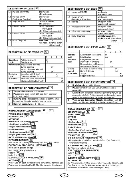
DESCRIPTION OF LEDS: 16 BESCHREIBUNG DER LEDS: 16L1 Impulse on M1+M2 on: impulseoff: no impulseL1 Impuls an M1+M2 an: Impulsaus: kein ImpulsL2 Impulse on M1 on: impulseL2 Impuls an M1 an: Impuls(Pedestrian Function) off: no impulse(Fußgänger-Funktion) aus: kein ImpulsL3 Stop function on: not activatedoff: activatedL3 Notstop an: sperrt nichtaus: Antrieb gesperrtL4 Infrared barrier on: IR barrier notinterruptedoff: IR barrier interruptedL4L5Infrarot-LichtschrankeInfrarot-Lichtschrankean: sperrt nichtaus: Antrieb sperrtan: sperrt nichtL5 Infrared barrier on: IR barrier notinterruptedoff: IR barrier interruptedL6 Motor Diagnoseaus: Antrieb sperrtblinkt langsam: O.K.blinkt schnell: AnschlüsseL6 Motor Diagnostic slow flash: O.K.fast flash: motor or motorprüfenwiring defectBESCHREIBUNG DER DIPSCHALTER 17DESCRIPTION OF DIP SWITCHES1 2 3 4Operation Automatic closing onLogic Step by step offParkfunction Impulses are detectedduring openingonNo impulses are tetectedduring openingoffElectrical Operation with E-Lock onLock Operation without E-Lock offIR barrier Stops and starts after release onStops and restarts directlyoffDESCRIPTION OF POTENTIOMETERSABCDTorque adjustment of both motorsPause:waits open form 8-200 sec. (only operationlogic: “automatic”)Running time : it is recommendable to set this timelonger then the gate needs to open or closeDelay of second wing: 0 - 25 sec.INSTALLATION OF ACCESSORIES 19 - 31POWER CONNECTION 19WARNING LIGHT 20ACTUATORMotor drive unit wiring diagram♦ Left hand installation 21♦ Right hand installation 22Dual installation♦ Left gate opens first♦ Right gate opens first2324GATE STATUS INDICATOR 25INFRARED BARRIER 26♦ IR barrier for opening and closing - (If using 1 IR barrier)EMERGENCY STOP SWITCH (OPTIONAL) 27If not used, please bridgeWALLCONTROL (OPTIONAL)Motor 1 28Motor 1 + 2 29ELECTRICAL LOCK (OPTIONAL) 30ANTENNA 31Please use an 22cm insulated cable as Antenna. (terminal 26)Please use a coaxial cable (75 Ohm) to transport the signals.17181 2 3 4Betriebs- Automatisch schließend anlogik Schrittweise ausBetriebs- Reagiert auf Impulselogik während des Öffnens anReagiert nicht auf Impulsewährend des ÖffnensausElektro- E-Schloß in Verwendung anschloß Ohne E-Schloß ausPhotozelle Stoppt anStoppt und öffnetausBESCHREIBUNG DER POTENTIOMETER 18A Krafteinstellung beider MotorenB Pause: wartet offen 8-200 Sek. (nur Betriebslogik:AutomatikC Laufzeit: Um korrekte Funktion zu gewährleisten, ist esnotwendig, daß der Antrieb noch einige Sekunden nachAnkunft am Endanschlag mit Strom versorgt wird.D Verzögerung des zweiten Flügels: Einstellbar von 0-25Sekunden. Notwendig bei sich überlappenden Toren.EINBAU VON ZUBEHÖR 19 - 31STROMANSCHLUß 19WARNLAMPE 20ANTRIEBDiagramm♦ Linkseinbau 21♦ Rechtseinbau 22Dualer Einbau♦ Linkes Tor öffnet zuerst♦ Rechtes Tor öffnet zuerst2324TORANZEIGE 25SICHERHEITSLICHTSCHRANKE 26♦ Lichtschranke zum Öffnen und Schließen - (bei Benutzungeiner Lichtschranke)NOTSTOPSCHALTER (OPTION) 27Bei Nichtverwendung brückenSCHLÜSSELSCHALTER (OPTION)Motor 1 28Motor 1 + 2 29ELEKTRO-SCHLOß (OPTION) 30ANTENNE 31Als Antenne wird ein 22cm langes Kabel verwendet (Klemme 26)Zum Transport des Funksignals wegen evt. Abschirmungen,verwenden Sie bitte ein Koaxialkabel (75 Ohm).GB6D
INITIAL SETTING OF MOTOR CONTROL SYSTEM(1) Connect the installation in accordance with wiring diagramsupplied.(2) Place both gates in half-open position and block the motors.(3) Adjust the motor controls to the following basic settings:A - Adjust torque to approx. 25 % (to be increased later)B - Switch off automatic closing (dip switch 2 OFF)C - Travel time approx. 50%.D - Switch off gate delay time (left end positon)(4) Switch on power supply.(5) Start the motor control by brigding terminal 20 and 21;both gates should then move in the "OPEN" direction.Should one or the other gate move in the "CLOSED"direction, then the connection wires to the correspondingmotor must be inverted (black, brown).Ensure the main power supply is off before invertingwires!(6) Repeat steps 5 and 6 until the required function isobtained.(7) In the case of overlapping gates, use potentiometer D toset the optimum gate delay time. For gates which do notoverlap or for operation with a single gate, thisadjustment is not necessary.(8) The travel time is adjusted with potentiometer C. It isrecommendable to set this time 2 or 3 seconds longerthan the gate actually needs to open or close.(9) Adjust the motor torque in sucha way that it is sufficientto stop the door by hand. Protection against damagesis only possible through installation of an IR barrier.When automatic closing is required, set Dip switch 1 to ONand use Potentiometer D to contol the waiting time.INITIAL SETTING OF REMOTE CONTROL 32The PTT-approved, charge-free radio remote control unitfunctions with a computer pre-programmed privatesecurity code (approximately 3.5 billion codepossibilities). In this way, your swing gate control unit canonly be activated by handset with the correct code. Theoperating range depends on local conditions.The receiver module of the motor control unit has a built-inself-learn function. It can be set in accordance with the preprogrammedcode of the handset by pressing the learnbutton (Illustration 32).The control unit comprises 2 learn channels. In this way, thehandset may be used to open or close one gate only or bothgates simultaneously. When, for example, channel 1 (2.1)receives the remote control code of the first control button ofthe handset, then only one gate is opened. When the secondchannel (2.2) is set in accordance with the remote control codeof the second control button, then both gates are operatedwhen this button is pressed.In order to configure the control PCB pre-programmed code inaccordance with the handset, the learn and transmit buttonsfor the required channel must be pressed and held until theassociated LED lights up briefly. When a multi-control handsetis used, this procedure must be repeated for each controlbutton and associated learn channel.Repeat this procedure for every transmitter.GRUNDEINSTELLUNG(1) Anlage gemäß Anleitung anschließen.(2) Beide Torflügel in halboffene Position bringen undverriegeln.(3) Motorsteuerung in folgende Grundeinstellung bringen:A - Krafteinstellung auf ca. 25% (evtl. später erhöhen)B - Dippschalter 2 Richtung OFFC - Laufzeit ca. 50%D - Potentiometer D auf Linksanschlag(4) Stromversorgung anschließen.(5) Betätigen Sie den an 20 und 21 angeschlossenenSchalter oder brücken Sie kurz die Kontakte. Sollte eineroder beide Motorflügel sich nicht in Richtung AUFbewegen, tauschen Sie die Steuerkabel des jeweiligenMotors (schwarz, braun).Achtung: Zuerst immer die Netzspannung abschalten.(6) Wiederholen Sie Schritte 5 und 6 bis sich die korrekteFunktion einstellt.(7) Sollten Sie überlappende Tore haben, stellen Sie mitPotentiometer D die Verzögerung ein.(8) Die Laufzeit einige Sekunden länger einstellen als dietatsächlich benötigte Zeit.(9) Stellen Sie die Kraftstärke so ein, daß Sie das Tor mitder Hand stoppen können. Sicherheit gegen Schädenerlangen Sie nur durch den Einsatz einerLichtschranke.Sollten Sie die Funktion “Automatisch schließen” wünschen,stellen Sie Dippschalter 1 auf ON und regulieren Sie mitPotentiometer D die Wartezeit.EINLERNEN DER FERNBEDIENUNG 32Die postzugelassene, gebührenfreie Funkfernsteuerungarbeitet mit einem per Computer vorprogrammiertenprivaten Sicherheitscode (ca. 3,5 MilliardenCodiermöglichkeiten). Damit kann Ihr <strong>Drehtorantrieb</strong> nurmit einem entsprechend eingelernten Handsender betriebenwerden.(max. 4 mit 3,5 Mrd. Codierung). Die Reichweite istvon örtlichen Begebenheiten abhängig.Das Empfängerteil der Motorsteuerung hat eine integrierteSelbstlernfunktion. Sie kann auf den vorprogrammiertenCode des Handsenders durch Drücken der Lerntasteeingestellt werden (Abb. 32).Die Steuerung besitzt zwei Lernkanäle. Sie kann damit durchentsprechendes Betätigen des Handsenders ein Tor oderbeide Tore gleichzeitig öffnen oder schließen. Erhältbeispielsweise Kanal 1 (2.1) den Fernbedienungscode desHandsenders, wird nur ein Flügel geöffnet. Lernen Sie denKanal 2 (2.2) der Fernbedienung an, können Sie mit dieserTaste beide Flügel betätigen.Um den Code einzuspeichern, drücken Sie die von Ihnengewählte Taste des Handsenders und halten diese fest.Drücken Sie mit der anderen Hand kurz die Lerntaste derElektronik.Wiederholen Sie den Vorgang für alle Handsender.LÖSCHEN PROGRAMMIERTERFERNBEDIENUNGSCODE:Drücken Sie die jeweilige Lerntaste (2.1 oder 2.2 - ca. 10Sekunden) auf der Empfängerplatine bis die Lern-LEDerlischt. Die zu dieser Lerntaste gehörenden “erlernten”Codierungen sind dann gelöscht.GB7D