Anleitungen Drehtorantrieb HC300/HC400 ... - Chamberlain
Anleitungen Drehtorantrieb HC300/HC400 ... - Chamberlain
Anleitungen Drehtorantrieb HC300/HC400 ... - Chamberlain

Erfolgreiche ePaper selbst erstellen
Machen Sie aus Ihren PDF Publikationen ein blätterbares Flipbook mit unserer einzigartigen Google optimierten e-Paper Software.
DFGBNL<strong>Anleitungen</strong>InstructionsInstructionsInstrukties<strong>Drehtorantrieb</strong> <strong>HC300</strong>/<strong>HC400</strong>Drehtoröffner SteuerelektronikAutomatisme portail à battants <strong>HC300</strong>/<strong>HC400</strong>Automatisme portail à battants Commande électroniqueSwing Gate Opener <strong>HC300</strong>/<strong>HC400</strong>Swing Gate Opener Logic Control BoxVleugelpoortaandrijving <strong>HC300</strong>/<strong>HC400</strong>Vleugelpoortaandrijving BesturingselektronicaDGBFür Service: (49) 6838/907-200 F Pour Service: 03-87-95-39-27For Service: 0800-31-78-47 NL Voor Service: 020-684-7978
START BY READING THESE IMPORTANT SAFETYRULESThese safety alert symbols mean Caution – apersonal safety or property damage instruction.Read these instructions carefully.This gate opener is designed and tested to offerreasonable safe service provided it is installedand operated in strict accordance with thefollowing safety rules.Failure to comply with the following instructions mayresult in serious personal injury or property damage.Keep gate balanced. Sticking or binding gates mustbe repaired. Do not attempt to repair the gatesyourself. Call for service.Handle tools and hardware carefully and do notwear rings, watches or loose clothing whileinstalling or servicing a gate opener.Installation and wiring must be in compliance withyour local building and electrical codes. Connect thepower cord only to properly earthed mains.Ensure that persons who install, maintain oroperate the gate opener follow these instructions.Keep this manual where it can be readily referencedduring maintenance.Disengage all existing gate locks to avoid damageto gate opener.CAUTION: Activate opener only when the gate isin full view, free of obstructions and opener isproperly adjusted. Do not allow children to playnear the gate.Disconnect electric power to the gate openerbefore making repairs.Keep additional accessories out of the reach ofchildren. Do not allow children to operate pushbutton(s) or remote control(s). Serious personalinjury from a closing gate may result from misuse ofthe opener.BEGINNEN SIE MIT LESEN DIESER WICHTIGENSICHERHEITSREGELNSolche Warnzeichen bedeuten “Vorsicht!”, eineAufforderung zur Beachtung, da ihre MißachtungPersonen- bzw. Sachschäden verursachen kann.Bitte lesen Sie diese Warnungen sorgfältig.Dieser Toröffner ist so konstruiert und geprüft,daß er bei Installation und Benutzung untergenauer Befolgung der anschließendenSicherheitsregeln angemessene Sicherheit bietet.Die Nichtbeachtung der folgenden Sicherheitsregeln kannernsthafte Personen- oder Sachschäden verursachen.Es ist wichtig, das Tor immer gut gangbar zuhalten. Tore die steckenbleiben oder verklemmen,sind unverzüglich zu reparieren.Versuchen Sienicht das Tor selbst zu reparieren. Bestellen Siedafür einen Fachmann.Beim Umgang mit Werkzeugen und KleinteilenVorsicht walten lassen und weder Ringe, Uhrennoch lose Kleidungsstücke tragen, wenn SieInstallations- oder Reparaturarbeiten an einem Torvornehmen.Elektrische Leitungen sind entsprechend den lokalenBau- und Elektroinstallationsvorschriften zu verlegen. Daselektrische Kabel darf nur an ein ordnungsgemäßgeerdetes Netz angeschlossen werden.Stellen Sie sicher, daß Personen, die den Antriebmontieren, warten oder bedienen diesen<strong>Anleitungen</strong> folgen.Bewahren Sie die Anleitung an einem Ort auf, andem schnell auf sie zurückgegriffen werden kann.Enffernen Sie bitte alle am Tor angebrachtenSchlösser um Schaden am Tor zu vermeiden.VORSICHT! Betätigen Sie den Öffner nur, wenn Siedas Tor voll im Blickfeld haben, sich dort keinebehindernden Gegenstände befinden und derÖffner richtig eingestellt ist. Kinder sollten nicht inTornähe bei Betätigung des Öffners spielen.Unterbrechen Sie den Storm zum Torantrieb bevorSie Reparaturen machen.Entfernen Sie zusätzliches Zubehör aus der Nähevon Kindern. Erlauben Sie Kindern nichtDrucktaster und Fernbedienungen zu bedienen.Schwere Verletzungen können durch ein sichschließendes Tor verursacht werden.Contents:Safety Rules: Page 1Contents of the carton: Page 2, Illustration 1Product description: Page 2 Illustrations 2 - 3Technical data: Page 2Installation: Pages 2-3, Illustrations 4 - 6Intallation of Wing Gate Actuator Unit:Page 3, Illustrations 7 - 12Instruction Manual Logic Control Box: Page 4Technical Features: Page 4Electrical Installation: Page 4, Illustration 13Summary of Motor Control Connections:Pages 5-6, Illustrations 14 - 18Installation of Accessories: Page6- Illustrations 19 - 31Initial Setting of Motor Control System: Page 7Initial Setting of Remote Control: Page 7, Illustration 32Warranty: Page 8Accessories: Page 12, Illustration 33Inhalt:Sicherheitsregeln: Seite 1Inhalt des Kartons: Seite 2, Abbildung 1Produktbeschreibung: Seite 2, Abbildungen 2 - 3Technische Daten: Seite 2Montage: Seite 2-3, Abbildungen 4 - 6Einbau des <strong>Drehtorantrieb</strong>es: Seite 3,Abbildungen 7 - 12Montageanleitung Elektronik: Seite 4Technische Eigenschaften: Seite 4Elektrische Installation: Seite 4, Abbildung 13Anschlußübersicht: Seite 5-6, Abbildungen 14 - 18Installation von Zubehör: Seite 6, Abbildungen 19 - 31Grundeinstellung: Seite 7Einstellung der Fernbedienung: Seite7, Abbildung 32Garantie: Seite 8Zubehör: Seite 12, Abbildung 33GB1D
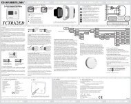
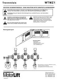
CONTENTS OF THE CARTON1 INHALT DES KARTONS1(1) Wing gate actuator unit for left-hand installation and/or(2) Wing gate actuator unit for right-hand installation(3) Mounting brackets(4) Installation accessories packHinge pins with circlips (2)Emergency opening handle (1)Capacitor (1)(5) Instruction manual(6) Warning light kit(7) IR Sensors(8) Transmitter(9) Control box(1) <strong>Drehtorantrieb</strong> für Linkseinbau und/oder(2) <strong>Drehtorantrieb</strong> für Rechtseinbau(3) Scharnierteile zur Befestigung(4) MontagezubehörbeutelBefestigungsbolzen mit Sicherheitsringen (2)Notentriegelung (1)Kondensator (1)(5) Montageanleitung(6) Warnlampe(7) Sicherheitslichtschranke(8) Handsender(9) SteuerungPRODUCT DESCRIPTION 2 - 3 PRODUKTBESCHREIBUNG 2 - 3<strong>HC300</strong>R, <strong>HC300</strong>L, <strong>HC400</strong>R+LScope of application: Motorized opening and closing ofgates.Illustration 3 shows a dimensional outline of the actuator arms.The actuator units are suitable for use with single and doublegates. For <strong>HC300</strong>, the maximum gate width may not exceed2.5 m and for <strong>HC400</strong> it may not exceed 3.0 m. Maximumweight 300 kg per gate.For design reasons, all wing gate actuator units, operatingwith linear movement, must follow the given installationdimensions. Some gate or post types may require recessingof the post or use of the longer stroke actuator, in order toachieve the installation dimensions.Technical data<strong>HC300</strong>R, <strong>HC300</strong>L, <strong>HC400</strong>R+LBestimmungsgemäßer Gebrauch: Motorisiertes Öffnen undSchließen von Toren.Abbildung 3 zeigt die Abmessungen der Antriebe.Die Antriebe sind für ein -und zweiflügelige Tore geeignet DieBreite eines Torflügels darf beim <strong>HC300</strong> nicht über 2,5 m,beim <strong>HC400</strong> nicht über 3,0 m betragen. Maximales Gewicht300kg pro Flügel.Bauartbedingt müssen bei allen <strong>Drehtorantrieb</strong>en, die mitlinearer Bewegung arbeiten, bestimmte Einbaumaßeeingeghalten werden. Je nach Beschaffenheit des Pfeilersoder Torflügels können diese Maße nur durch Ausparungenam Pfeiler oder durch Verwendung von Antrieben mitgrößerem Hub erreicht werden.<strong>HC300</strong> <strong>HC400</strong>Power supply 230V - 50Hz 230V - 50HzCapacitor 10 µF 10 µFCurrent drawn 1.5 A 1.5 APower 350W 350WOpening angle 110° max 110° maxMax. cycles/hours 20 20Force 200kg 200kgMax. actuator unit length 97cm 112cmMotor thermal overload switch 140 °C 140 °CRated weight of motor 6.5kg 7kgDimensions see fig.3 see fig.3Speed 1.5cm/s 1.5cm/sIP Rating (motor) IP54 IP54INSTALLATION 4 - 6PreparationsBefore installation, please check contents of packaging.Please refer to Illustration 1.Ensure your gate equipment functions correctly.Please keep in mind, that you will need parts not included inthe packaging (tubes, cable, screws, rawlplug and so on)Installation preparationAs an example, Illustration 4 illustrates installation with astone or steel post construction. The installation dimensionsfor the gate actuator unit are dependant on the fasteningpoints of gate to post.llustration 5 shows the meaning of installation dimensions Aand B. The measurements chosen also determine the openingand closing times and the maximum opening angle of the gate.Sample for A=14cm and B=14cm (approx. 90 0 )Technische Daten<strong>HC300</strong> <strong>HC400</strong>Netzanschluß 230V - 50Hz 230V - 50HzKondensator 10 µF 10 µFStromaufnahme 1.5 A 1.5 ALeistungsaufnahme 350W 350WÖffnungswinkel 110° max 110° maxMax. Zyklen/Std. 20 20Zugkraft 200kg 200kgMax. Antriebslänge 97cm 112cmMotorthermoschutz 140 °C 140 °CNettogewicht Motor 6.5kg 7kgAbmessungen siehe Abb..3 siehe Abb..3Geschwindigkeit 1.5cm/s 1.5cm/sIP Werte (Motor) IP54 IP54MONTAGE 4 - 6VorbereitungenÜberprüfen Sie bitte vor der Montage den Inhalt derVerpackung auf Vollständigkeit. Siehe Abbildung 1.Stellen Sie die einwandfreie Arbeitsweise Ihrer Torvorrichtungsicher. Bedenken Sie, daß Sie noch Material benötigen, daßsich verständlicherweise nicht in unserem Lieferumfangbefinden kann (Leerrohr, Kabel, Schrauben, Dübel etc.)MontagevorbereitungenBeispiele für eine Montage an Mauerwerk oder Stahlpfeilernsind in Abb. 4 dargestellt. Die Montagemaße eines Torantriebessind von der Befestigung des Torflügels am Pfeiler abhängig.Abb. 5 zeigt die Bedeutung der Einbaumaße A und B. Diegewählten Maße bestimmen gleichzeitig die Öffnungs- undSchließzeit und den maximalen Öffungswinkel eines Torflügels.Beispiel für A=14cm und B=14cm (für ca. 90 0 )GB2D
As a rule:B greater than AA greater than Bslower, smoother closing, gateopens faster.greater opening angle, however, whenclosing, the gate makes a harder andfaster contact with the post stop.For an opening angle of 90°, addition of the dimensions Aand B always gives the total actuator stroke. When a gateopening angle greater than 90° is required, dimension B willneed to be reduced accordingly.In order to obtain the optimum dimensions, it may benecessary to shorten or lengthen the hinge plates supplied.In the case of a new gate, dimensions A and B may bechanged when the gate angle brackets are fastened to thepost accordingly. Before the installation dimensions arefinalised, ensure that the gate actuator unit does not touchthe post when moving.Please refer to Illustration 6 - Table. (If only one value isstated: value for <strong>HC300</strong>/<strong>HC400</strong> identical.)To avoid undesirable jerking movement, the gate should bestable and the angle brackets should have as little play aspossible. The easier the gate movement, the finer the torqueadjustment. Fragile wooden gates should be reinforced witha metal frame.Grundsätzlich gilt:B größer als A langsameres, sanftes Schließen, Flügelwird beim Öffnen schnellerA größer als B großer Öffnungswinkel, Flügel fährt aberbeim Schließen schnell und hart an denPfeileranschlag anFür einen Öffnungswinkel von 90° ergibt die Addition derMaße A und B immer den gesamten Kolbenhub. Soll derTorflügel weiter als 90° aufgehen, muß das Maß Bentsprechend verkleinert werden.Um optimale Maße zu erreichen, kann es nötig sein, diemitgelieferte Scharnierplatte zu kürzen oder zu verlängern.Bei neu anzufertigenden Toren kann, wenn die Torangeln anden Pfeilern entsprechend montiert werden, Einfluß auf dieMaße A und B genommen werden. Bevor die Anbaumaßeendgültig festgelegt werden, sollte immer geprüft werden, obder Antrieb beim Schwenken nicht am Pfeiler anecken könnte.Siehe Abb. 6 - Beispeiltabelle. (Bei Angabe nur einesMeßwertes: Meßwert für <strong>HC300</strong>/<strong>HC400</strong> identisch.)Um störende Pendelbewegungen zu vermeiden sollte derFlügel stabil und die Torangeln möglichst spielfrei sein. Jeleichtgängiger der Flügel, desto feinfühliger ist die Krafteinzustellen. Labile Holztore sollten mit einem Metallrahmenverstärkt werden.INSTALLATION OF WING GATEACTUATOR UNIT 7 - 12(1) Fasten the hinge elements to the gate and post inaccordance with the installation dimensions calculatedbeforehand. The smaller element is to be fitted to the gateand the larger fitted to the post (Illustration 7).NOTE: The hinge elements must be vertically aligned toone anotherThe force which the actuator unit applies against the post isconsiderable. A steel post is the most suitable from thestability point of view. Quite acceptable installationdimensions are usually obtained when the hinge platessupplied are welded directly onto the post.In the case of thick stone or concrete posts, the hingeelement must be welded onto a support plate and thenfastened in such a way that the dowels cannot become looseduring operation. For this purpose, glued shear connectors, inwhich a threaded rod is inserted into the wall without pressure,are more suitable than steel or plastic expansion dowels.In the case of brick walls, a large steel plate, coveringseveral bricks, should be screwed onto the wall and the hingeplate welded onto this base plate. An angle iron over thecorner of a post is also a suitable fastening support.(2) Place a water-tight junction box next to the hinge plate onthe post. The Wing gate motor supply cable is led into thisbox from below (Illustration 8).(3) Using the hexagonal handle supplied, release the actuatorunit by loosening the emergency release screw a half-turn in theclockwise direction. Then extend the actuator to its maximumlength. Re-tighten the actuator unit by turning the screw a halfturnin the anticlockwise direction (Illustrations 9 and 10).With the gate closed, slide the fully extended actuator ontothe hinge element and fasten it using the hinge pins suppliedin the accessories pack. The hinge pins are blocked usingthe circlips which are inserted into the bottom groove of thehinge pins (Illustrations 11 and 12).MONTAGE DES DREHTORANTRIEBES 7 - 12(1) Bringen Sie gemäß den zuvor ermittelten Einbaumaßendie Scharnierteile an Torflügel und Pfeiler an. Das kleinereTeil ist für den Torflügel vorgesehen, das größere für denPfeiler (Abb. 7).ANNMERKUNG: Die Scharnierteile müssen zueinanderwaagerecht ausgerichtet sein.Die Kräfte, mit denen sich der Antrieb gegen den Pfeilerabstützt, sind sehr groß. Ein Stahlpfeiler bereitet von derStabilität her die wenigsten Probleme. Meistens ergeben sichschon akzeptable Einbaumaße, wenn die mitgelieferteScharnierplatte direkt an den Pfeiler geschweißt wird.Bei dicken Stein- oder Betonpfosten muß das Scharnierteilauf eine Trägerplatte geschweißt und so befestigt werden,daß sich die Dübel im Betrieb nicht lockern können. Besserals Stahl- oder Kunststoff-Spreizdübel eignen sich hierzuKlebe-Verbundanker, bei denen ein Gewindestift Spannungsfreiim Mauerwerk eingeklebt wird.Bei gemauerten Pfeilern sollte eine größere Stahlplatte,mehrere Steine überdeckend, angeschraubt werden, auf diedann die Scharnierplatte aufgeschweißt werden kann. Gutzur Befestigung eignet sich auch eine um die Pfeilerkantebefestigte Winkelplatte.(2) Setzen Sie neben die Scharnierplatte am Pfeiler einewasserdichte Verteilerdose. Hier wird das Anschlußkabel des<strong>Drehtorantrieb</strong>es von unten eingeführt (Abb. 8).(3) Entriegeln Sie den Antrieb, indem Sie dieNotentriegelungsschraube mit dem mitgeliefertenSechskantschlüssel um eine halbe Drehung im Uhrzeigersinndrehen. Ziehen Sie dann den Kolben auf fast maximale Längeheraus. Verriegeln Sie anschließend den Antrieb wieder durcheine halbe Drehung im Gegenuhrzeigersinn (Abb. 9 und 10).Schieben Sie anschließend bei geschlossenem Torflügel den aufmaximal zulässige Länge ausgezogenen Antrieb auf dieScharnierteile auf und befestigen Sie ihn mit Hilfe der imZubehörbeutel enthaltenen Bolzen. Die Bolzen werden durchdie auf die untere Bolzennut aufzuschiebenden Sicherheitsringegesichert (Abb. 11 und 12).GB3D
2.5m Swing Gate Opener - <strong>HC300</strong>3.0m Swing Gate Opener - Hc400<strong>Chamberlain</strong>Alfred-Nobel-Str. 4D-66793 Saarwelligen(49) 6838/907-2001123245 CHAMBERLAININSTRUCTION MANUAL6 789345<strong>HC300</strong>: 92 cm / <strong>HC400</strong>: 110 cm<strong>HC300</strong>: 62 cm<strong>HC400</strong>: 72 cm6A8 10 12 14 16 18 20 22 248 100 0 110 0 120 0 125 0 110 0 /131 0 100 0 /115 0 93 0 /120 0 88 0 /109 0 84 0 /102 010 99 0 108 0 115 0 121 0 101 0 /125 0 93 0 /128 0 89 0 /113 0 83 0 /104 0B 12 95 0 105 0 110 0 105 0 /118 0 93 0 /122 0 86 0 /118 0 82 0 /105 014 95 0 100 0 108 0 95 0 /115 0 87 0 /118 016 94 0 100 0 106 0 93 0 /110 018 97 0 97 020 91 09
JP17 891011121314-+1 2 3 4 5 6 7 8 9 10 1112 13 14 15 16 17 18 19 20 21 22 23 24 25 26 27151617L6L5 L4 L3 L2 L1JP2181920• • •L1 PE N230V 230VEarth/Erdung/21222 6 7 8Capacitor/Kondensator/CondensateurCapacitor/Kondensator/Condensateur2 6 7 8schwarz, noirblau, bleubraun, marrongelb/grün, jaune/vertblack1blue23 brownyellow/green4blackbluebrownyellow/greenschwarz, noir12 blau, bleu3 braun, marrongelb/grün, jaune/vert410
23 242 Capacitor/Kondensator/Condensateur6 7 8 9 10 11Capacitor/Kondensator/Condensateur2 Capacitor/Kondensator/Condensateur6 7 8 9 10 11Capacitor/Kondensator/Condensateur1 2 3 4 1 2 3 41 2 3 4 1 2 3 4brown/braun/marronblue/blau/bleublack/schwarz/noiryellow/green,gelb/grün,jaune/vertblack/schwarz/noirblue/blau/bleubrown/braun/marronyellow/green,gelb/grün,jaune/vertbrown/braun/marronblue/blau/bleublack/schwarz/noiryellow/green,gelb/grün,jaune/vertblack/schwarz/noirblue/blau/bleubrown/braun/marronyellow/green,gelb/grün,jaune/vertLeftRightLeftRight2526-+12 1314 15 16 17 18 19 20 21 22 23 24 25 26 2714 15 16 17 18 1920 21 22 2327282930-+12 1314 15 16 17 18 19 20 21 22 23 24 25 26 2717 18 19 20 21 22 2317 18 19 20 21 22 2322 23 24 25 26 27➔SWITCH➔SWITCH➔SWITCH31 32222 23 24 25 26 27175 Ω10-15m11
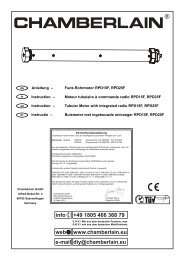
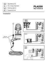
TECHNICAL FEATURESPower supply230V-50HzAbsorbed power10WMax. motor load700WMax. load on accessories 0.9AAuxilliary output24V ACProtection fuses 4Operating logicStep by step/AutomaticHousing Dimensions 90x195x250mmHousing drgree ofProtection IP54TECHNISCHE EIGENSCHAFTENNetzanschluß230V-50HzHzStromverbrauch10WMax.Motorbelastung 700WMax. Belastung Zubehör 0.9AMax. Belastung E-Schloß 24V ACSicherungen 4BetriebslogikSchritt für Schritt/AutomatikAbmessungen90x195x250mmSchutzIP54ELECTRICAL INSTALLATIONThe electronic control unit supplied is required for operationof the wing gate actuator. This control unit comprises anelectronic microprocessor-control system employing the latesttechnology. It may be used for the connection of 1 or 2motors and offers all connection possibilities and functionsnecessary for safe and reliable operation.The electrical connections for single- or double gates aregiven in Illustration 13.The control box containing the motor control module is to befitted with cable entry at bottom. It should not be continuouslyexposed to direct sunlight. For weather protection, werecommend the fitting of a small protection roof.Thanks to the electronic control unit, fine adjustment of thepush-pull torque is possible. When correctly adjusted, gatemovement can be easily blocked by hand.For the OPEN and CLOSED positions, the gate requires astable end stop as the swing gate actuator unit is notfitted with limit switches and the electronic controls areswitched off by time.13ELEKTRISCHE INSTALLATIONZum Betrieb des <strong>Drehtorantrieb</strong>s ist die mitgelieferteelektronische Steuerung erforderlich. Bei dieser Motorsteuerunghandelt es sich um eine mikroprozessorgesteuerte Elektronikmit modernster Technik. Sie ist für den Anschluß von bis zu 2Motoren geeignet und hat alle für den sicheren Betriebnotwendigen Anschlußmöglichkeiten und Funktionen.Der elektrische Anschluß ist für Einflügel- und Zweiflügel-Tore ineiner Übersicht in Abb. 13 dargestellt.Die Steuerbox mit der Motorsteuerung ist mit denKabeldurchführungen nach unten zu montieren. Sie darfdirekter Sonneneinstrahlung nicht dauernd ausgesetzt sein. Esempfiehlt sich, als Schutz vor Regen ein kleines Schutzdach zumontieren.Das Tor läßt sich bei richtiger Einstellung von Handfesthalten.Während des Laufes kann das Tor jederzeit über Funk, Tasteroder Schlüsselschalter gestoppt werden.Der Torflügel benötigt für "AUF-" und "ZU"-Stellungeinen stabilen Anschlag, da die <strong>Drehtorantrieb</strong>e keineEndschalter besitzen und die Abschaltung der Elektroniküber die Zeit erfolgt.13GB4D
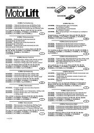
SUMMARY OFMOTOR CONTROL CONNECTIONS 14 - 18Description of connectionsMain supply connections:Terminal 1 L1 - 230 V (black)Terminal 2 PE (green/yellow)Terminal 3 N (blue)Warning light connections:Terminal 4 NTerminal 5 L1 (230V)Motor connections:First Motor (M1):Terminal 6 M1 actuator unit direction OPEN(+ capacitor)Terminal 7 N BlueTerminal 8 M1 actuator unit direction CLOSE(+ capacitor)Second Motor (M2):Terminal 9 M2 actuator unit direction OPEN(+ capacitor)Terminal 10 N BlueTerminal 11 M2 actuator unit direction CLOSE(+ capacitor)Gate status LEDTerminal 12 LED (2 Volt)Terminal 13 LED (2 Volt)Off - gate openingOn - gate closingSlow flashing - gate openingFast flashing - gate closingInfrared light detectorTerminal 14 Photocell (NC)Terminal 15 COMTerminal 16 Photocell (NC)(If the IR barrier is not used, bridge terminals14,15 and 16 must be bridged!)Description of connectionsEmergency-Stop-functionTerminal 17 COMTerminal 18 Stop (NC) or bridge between 17 and 18Control circuit connections:Terminal 19 Outside button (NO) Motor 1 (Pedestrian function)Terminal 20 COMTerminal 21 Outside button (NO) Motor 1 + 2Auxiliary equipment connections:Terminal 22 Supply voltage 24 V AC (500 mA max.)Terminal 23 Supply voltage 24 V ACElectric lock connections:Terminal 24 Supply voltage 12 V ACTerminal 25 Supply voltage 12 V ACAntenna connections:Terminal 26 Antenna (wire)Terminal 27 ShieldDESCRIPTION OF JUMPERS 15JP1: MOTOR SELECTION JUMPEROPEN: (No Jumper): Use only for single wing gates(Motor 1 operation only).CLOSED: (With Jumper): Use for double wing gates(Motor 1 and 2 operation).JP2: TWO CHANNEL RECEIVER JUMPER SELECTIONOPEN: (No Jumper): Receiver channel 2 is activated.CLOSED: (With Jumper): Receiver channel 2 is not activated.ANSCHLUßÜBERSICHT 14 - 18Beschreibung der KlemmenbelegungAnschluß der Zuleitung:Klemme 1 L1 - 230 V (schwarz)Klemme 2 PE (grün/gelb)Klemme 3 N (blau)Anschluß der Warnlampe:Klemme 4 NKlemme 5 L1 (230V)Anschlüsse der Motoren:Erster Motor (M1):Klemme 6 M1 Fahrtrichtung AUF(+ Kondensator)Klemme 7 N BlauKlemme 8 M1 Fahrtrichtung ZU(+ Kondensator)Zweiter Motor (M2):Klemme 9 M2 Fahrtrichtung AUF(+ Kondensator)Klemme 10 N BlauKlemme 11 M2 Fahrtrichtung ZU(+ Kondensator)Anzeige LEDKlemme 12 LED (2 Volt)Klemme 13 LED (2 Volt)AUS - Tor geschlossenAN - Tor offenBlinkt langsam - Tor öffnetBlinkt schnell - Tor schließtInfrarot-LichtschrankeKlemme 14 Photozelle (NC)Klemme 15 COMKlemme 16 Photozelle (NC)(Ohne Lichtschranke - Brücke zwischen 14, 15und16!)Beschreibung der KlemmenbelegungNOTSTOP-FUNCTIONKlemme 17 COMKlemme 18 Stop (NC) ohne Notstopschalter Brückezwischen 17 und 18Anschluß der Steuerleitungen:Klemme 19 Taster extern (NO) Motor 1 (Fußgänger-Funktion)Klemme 20 COMKlemme 21 Taster extern (NO) Motor 1 + 2Anschluß für Zusatzgeräte & Lichtschranke:Klemme 22 Versorgungsspannung 24 V AC (500 mA max.)Klemme 23 Versorgungsspannung 24 V ACAnschluß für Elektroschloß:Klemme 24 Versorgungsspannung 12 V ACKlemme 25 Versorgungsspannung 12 V ACAnschluß für Antenne:Klemme 26 Antenne (Leiter)Klemme 27 AbschirmungBESCHREIBUNG DER JUMPER 15JP1: MOTOROPEN: (ohne Jumper): Nur für einflügelige Tore(nur Motor 1 Bedienung).CLOSED: (mit Jumper): Nur für zweiflügelige Tore(Motor 1 und 2 Bedienung).JP2: FUNK (ERMÖGLICHT ÖFFNEN EINES FLÜGELS)OPEN: (ohne Jumper): Empfänger Kanal 2 wird aktiviert.CLOSED: (mit Jumper): Empfänger Kanal 2 wird nicht aktiviert.GB5D
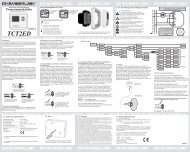
DESCRIPTION OF LEDS: 16 BESCHREIBUNG DER LEDS: 16L1 Impulse on M1+M2 on: impulseoff: no impulseL1 Impuls an M1+M2 an: Impulsaus: kein ImpulsL2 Impulse on M1 on: impulseL2 Impuls an M1 an: Impuls(Pedestrian Function) off: no impulse(Fußgänger-Funktion) aus: kein ImpulsL3 Stop function on: not activatedoff: activatedL3 Notstop an: sperrt nichtaus: Antrieb gesperrtL4 Infrared barrier on: IR barrier notinterruptedoff: IR barrier interruptedL4L5Infrarot-LichtschrankeInfrarot-Lichtschrankean: sperrt nichtaus: Antrieb sperrtan: sperrt nichtL5 Infrared barrier on: IR barrier notinterruptedoff: IR barrier interruptedL6 Motor Diagnoseaus: Antrieb sperrtblinkt langsam: O.K.blinkt schnell: AnschlüsseL6 Motor Diagnostic slow flash: O.K.fast flash: motor or motorprüfenwiring defectBESCHREIBUNG DER DIPSCHALTER 17DESCRIPTION OF DIP SWITCHES1 2 3 4Operation Automatic closing onLogic Step by step offParkfunction Impulses are detectedduring openingonNo impulses are tetectedduring openingoffElectrical Operation with E-Lock onLock Operation without E-Lock offIR barrier Stops and starts after release onStops and restarts directlyoffDESCRIPTION OF POTENTIOMETERSABCDTorque adjustment of both motorsPause:waits open form 8-200 sec. (only operationlogic: “automatic”)Running time : it is recommendable to set this timelonger then the gate needs to open or closeDelay of second wing: 0 - 25 sec.INSTALLATION OF ACCESSORIES 19 - 31POWER CONNECTION 19WARNING LIGHT 20ACTUATORMotor drive unit wiring diagram♦ Left hand installation 21♦ Right hand installation 22Dual installation♦ Left gate opens first♦ Right gate opens first2324GATE STATUS INDICATOR 25INFRARED BARRIER 26♦ IR barrier for opening and closing - (If using 1 IR barrier)EMERGENCY STOP SWITCH (OPTIONAL) 27If not used, please bridgeWALLCONTROL (OPTIONAL)Motor 1 28Motor 1 + 2 29ELECTRICAL LOCK (OPTIONAL) 30ANTENNA 31Please use an 22cm insulated cable as Antenna. (terminal 26)Please use a coaxial cable (75 Ohm) to transport the signals.17181 2 3 4Betriebs- Automatisch schließend anlogik Schrittweise ausBetriebs- Reagiert auf Impulselogik während des Öffnens anReagiert nicht auf Impulsewährend des ÖffnensausElektro- E-Schloß in Verwendung anschloß Ohne E-Schloß ausPhotozelle Stoppt anStoppt und öffnetausBESCHREIBUNG DER POTENTIOMETER 18A Krafteinstellung beider MotorenB Pause: wartet offen 8-200 Sek. (nur Betriebslogik:AutomatikC Laufzeit: Um korrekte Funktion zu gewährleisten, ist esnotwendig, daß der Antrieb noch einige Sekunden nachAnkunft am Endanschlag mit Strom versorgt wird.D Verzögerung des zweiten Flügels: Einstellbar von 0-25Sekunden. Notwendig bei sich überlappenden Toren.EINBAU VON ZUBEHÖR 19 - 31STROMANSCHLUß 19WARNLAMPE 20ANTRIEBDiagramm♦ Linkseinbau 21♦ Rechtseinbau 22Dualer Einbau♦ Linkes Tor öffnet zuerst♦ Rechtes Tor öffnet zuerst2324TORANZEIGE 25SICHERHEITSLICHTSCHRANKE 26♦ Lichtschranke zum Öffnen und Schließen - (bei Benutzungeiner Lichtschranke)NOTSTOPSCHALTER (OPTION) 27Bei Nichtverwendung brückenSCHLÜSSELSCHALTER (OPTION)Motor 1 28Motor 1 + 2 29ELEKTRO-SCHLOß (OPTION) 30ANTENNE 31Als Antenne wird ein 22cm langes Kabel verwendet (Klemme 26)Zum Transport des Funksignals wegen evt. Abschirmungen,verwenden Sie bitte ein Koaxialkabel (75 Ohm).GB6D
INITIAL SETTING OF MOTOR CONTROL SYSTEM(1) Connect the installation in accordance with wiring diagramsupplied.(2) Place both gates in half-open position and block the motors.(3) Adjust the motor controls to the following basic settings:A - Adjust torque to approx. 25 % (to be increased later)B - Switch off automatic closing (dip switch 2 OFF)C - Travel time approx. 50%.D - Switch off gate delay time (left end positon)(4) Switch on power supply.(5) Start the motor control by brigding terminal 20 and 21;both gates should then move in the "OPEN" direction.Should one or the other gate move in the "CLOSED"direction, then the connection wires to the correspondingmotor must be inverted (black, brown).Ensure the main power supply is off before invertingwires!(6) Repeat steps 5 and 6 until the required function isobtained.(7) In the case of overlapping gates, use potentiometer D toset the optimum gate delay time. For gates which do notoverlap or for operation with a single gate, thisadjustment is not necessary.(8) The travel time is adjusted with potentiometer C. It isrecommendable to set this time 2 or 3 seconds longerthan the gate actually needs to open or close.(9) Adjust the motor torque in sucha way that it is sufficientto stop the door by hand. Protection against damagesis only possible through installation of an IR barrier.When automatic closing is required, set Dip switch 1 to ONand use Potentiometer D to contol the waiting time.INITIAL SETTING OF REMOTE CONTROL 32The PTT-approved, charge-free radio remote control unitfunctions with a computer pre-programmed privatesecurity code (approximately 3.5 billion codepossibilities). In this way, your swing gate control unit canonly be activated by handset with the correct code. Theoperating range depends on local conditions.The receiver module of the motor control unit has a built-inself-learn function. It can be set in accordance with the preprogrammedcode of the handset by pressing the learnbutton (Illustration 32).The control unit comprises 2 learn channels. In this way, thehandset may be used to open or close one gate only or bothgates simultaneously. When, for example, channel 1 (2.1)receives the remote control code of the first control button ofthe handset, then only one gate is opened. When the secondchannel (2.2) is set in accordance with the remote control codeof the second control button, then both gates are operatedwhen this button is pressed.In order to configure the control PCB pre-programmed code inaccordance with the handset, the learn and transmit buttonsfor the required channel must be pressed and held until theassociated LED lights up briefly. When a multi-control handsetis used, this procedure must be repeated for each controlbutton and associated learn channel.Repeat this procedure for every transmitter.GRUNDEINSTELLUNG(1) Anlage gemäß Anleitung anschließen.(2) Beide Torflügel in halboffene Position bringen undverriegeln.(3) Motorsteuerung in folgende Grundeinstellung bringen:A - Krafteinstellung auf ca. 25% (evtl. später erhöhen)B - Dippschalter 2 Richtung OFFC - Laufzeit ca. 50%D - Potentiometer D auf Linksanschlag(4) Stromversorgung anschließen.(5) Betätigen Sie den an 20 und 21 angeschlossenenSchalter oder brücken Sie kurz die Kontakte. Sollte eineroder beide Motorflügel sich nicht in Richtung AUFbewegen, tauschen Sie die Steuerkabel des jeweiligenMotors (schwarz, braun).Achtung: Zuerst immer die Netzspannung abschalten.(6) Wiederholen Sie Schritte 5 und 6 bis sich die korrekteFunktion einstellt.(7) Sollten Sie überlappende Tore haben, stellen Sie mitPotentiometer D die Verzögerung ein.(8) Die Laufzeit einige Sekunden länger einstellen als dietatsächlich benötigte Zeit.(9) Stellen Sie die Kraftstärke so ein, daß Sie das Tor mitder Hand stoppen können. Sicherheit gegen Schädenerlangen Sie nur durch den Einsatz einerLichtschranke.Sollten Sie die Funktion “Automatisch schließen” wünschen,stellen Sie Dippschalter 1 auf ON und regulieren Sie mitPotentiometer D die Wartezeit.EINLERNEN DER FERNBEDIENUNG 32Die postzugelassene, gebührenfreie Funkfernsteuerungarbeitet mit einem per Computer vorprogrammiertenprivaten Sicherheitscode (ca. 3,5 MilliardenCodiermöglichkeiten). Damit kann Ihr <strong>Drehtorantrieb</strong> nurmit einem entsprechend eingelernten Handsender betriebenwerden.(max. 4 mit 3,5 Mrd. Codierung). Die Reichweite istvon örtlichen Begebenheiten abhängig.Das Empfängerteil der Motorsteuerung hat eine integrierteSelbstlernfunktion. Sie kann auf den vorprogrammiertenCode des Handsenders durch Drücken der Lerntasteeingestellt werden (Abb. 32).Die Steuerung besitzt zwei Lernkanäle. Sie kann damit durchentsprechendes Betätigen des Handsenders ein Tor oderbeide Tore gleichzeitig öffnen oder schließen. Erhältbeispielsweise Kanal 1 (2.1) den Fernbedienungscode desHandsenders, wird nur ein Flügel geöffnet. Lernen Sie denKanal 2 (2.2) der Fernbedienung an, können Sie mit dieserTaste beide Flügel betätigen.Um den Code einzuspeichern, drücken Sie die von Ihnengewählte Taste des Handsenders und halten diese fest.Drücken Sie mit der anderen Hand kurz die Lerntaste derElektronik.Wiederholen Sie den Vorgang für alle Handsender.LÖSCHEN PROGRAMMIERTERFERNBEDIENUNGSCODE:Drücken Sie die jeweilige Lerntaste (2.1 oder 2.2 - ca. 10Sekunden) auf der Empfängerplatine bis die Lern-LEDerlischt. Die zu dieser Lerntaste gehörenden “erlernten”Codierungen sind dann gelöscht.GB7D
DELETION OF PROGRAMMED REMOTE-CONTROLCODES:Press the corresponding learn button (2.1 or 2.2 - approx.10 seconds) on the receiver PCB until the learn LED goesoff. The code memorised with this learn button has now beendeleted.REPROGRAMMING:When reprogramming, the above-mentioned coding steps mustbe repeated for all remote-control handsets in operation andtheir control buttons.The operating range of the remote-control unit depends on localconditions. Press and hold the button on the handset (approx. 2seconds) until the gate begins to move.In the PTT-approved frequency range for the radio control ofgates, there are also medical, industrial, scientific, military andhousehold radio systems in operation, some of which have avery high transmission range. The close proximity of such aradio installation could lead to a reduction in operating range ortemporary interference in your radio remote-control system.NEUPROGRAMMIEREN:Zum Neuprogrammieren sind die genannten Schritte für dieCodierung für alle in Betrieb befindlichen Fernbedienungenbzw. ihrer Bedienungstasten zu wiederholen.Die Reichweite der Funkfernsteuerung ist von den örtlichenGegebenheiten abhängig. Halten Sie die Taste amHandsender solange gedrückt (ca. 2 Sekunden), bis eineBewegung des Tores erkennbar ist.In den von der Deutschen Bundespost genehmigtenFrequenzbereichen für Torantriebe gibt es auch Funkanlagenfür medizinische, industrielle, wissenschaftliche, militärischeund häusliche Zwecke mit zum Teil sehr hohenSendeleistungen. Befinden Sie sich in der Nähe solcherFunkanlagen, kann das zu einer geringeren Reichweite oderzu vorübergehenden Störungen Ihrer Funkfernsteuerungführen.Ihre Funkfernsteuerung ist digitalcodiert, d.h. eineunbeabsichtigte Betätigung des Torantriebes kann nahezuausgeschlossen werden.WARRANTYCHAMBERLAIN warrants to the first retail purchaser of thisproduct that the product shall be free from any defect inmaterials and/or workmanship for a period of 24 full months(2 years) from the date of purchase for Model <strong>HC300</strong>/400and the Electronic Control Upon receipt of the product, thefirst retail purchaser is under obligation to check the productfor any visible defects.Conditions: The warranty is strictly limited to the reparationor replacement of the parts of this product which are found tobe defective and does not cover the costs or risks oftransportation of the defective parts or product.This warranty does not cover non-defect damage caused byunreasonable use (including use not in complete accordancewith CHAMBERLAIN's instructions for installation, operationand care; failure to provide necessary maintenance andadjustment, or any adaptations of or alterations to theproducts), labor charges for dismantling or reinstalling of arepaired or replaced unit or replacement batteries.A product under warranty which is determined to be defectivein materials and/or workmanship will be repaired or replaced(at CHAMBERLAIN's option) at no cost to the owner for therepair and/or replacement parts and/or product. Defectiveparts will be repaired or replaced with new or factory rebuiltparts at CHAMBERLAIN's option.This warranty does not affect the purchaser's statutory rightsunder applicable national legislation in force nor thepurchaser's rights against the retailer arising from theirsales/purchase contract. In the absence of applicablenational or EC legislation, this warranty will be thepurchaser's sole and exclusive remedy and neitherCHAMBERLAIN nor its affiliates or distributors shall be liablefor any incidental or consequential damages for any expressor implied warranty relating to this product.No representative or person is authorized to assume forCHAMBERLAIN any other liability in connection with the saleof this product.GARANTIECHAMBERLAIN garantiert dem ersten Käufer, der das Produktim Einzelhandel erwirbt (erster "Einzelhandelskäufer") daß es,ab dem Datum des Erwerbs volle 24 Monate (2 Jahre) langvon jeglichen Materialschäden bzw. Herstellungsfehlern frei ist.Diese Garantie gilt für die Modelle <strong>HC300</strong>/<strong>HC400</strong> und dieElektronische Steuerung. Bei Empfang des Produkts obliegtes dem ersten Einzelhandelskäufer, dieses auf sichtbareSchäden zu prüfen.Bedingungen: Die vorliegende Garantie ist das einzigeRechtsmittel, das dem Käufer gesetzmäßig wegen Schädenzusteht, die mit einem defekten Teil bzw. Produkt inVerbindung stehen bzw. sich aus einem solchen ergeben. Dievorliegende Garantie beschränkt sich ausschließlich aufReparatur bzw. Ersatz der Teile dieses Produkts, die alsschadhaft befunden werden.Die vorliegende Garantie gilt nicht für Schäden, die nicht aufDefekte sondern auf den unrichtigen Gebrauch zurückzuführensind (d. h. einschließlich jedweder Benutzung, die nicht genauden <strong>Anleitungen</strong> bzw. Anweisungen der Firma CHAMBERLAINhinsichtlich Installation, Betrieb und Pflege entspricht, sowie desVersäumnisses, erforderliche Instandhaltungs- undJustierungsarbeiten rechtzeitig durchzuführen, bzw. derDurchführung von Adaptierungen oder Veränderungen an diesemProdukt). Sie deckt auch nicht die Arbeitskosten für den Ausbaubzw. den Wiedereinbau eines reparierten oder ersetzten Gerätsoder dessen Ersatzbatterien. Ein Produkt im Rahmen derGarantie, hinsichtlich dessen entschieden wird, daß esMaterialschäden bzw. Herstellungsfehler aufweist, wird demEigentümer ohne Kosten für Reparatur bzw. Ersatzteile nachGutdünken der Firma CHAMBERLAIN repariert oder ersetzt.Sollte das Produkt während der Garantiezeit defekt erscheinen,so wenden Sie sich bitte an die Firma, von der Sie esursprünglich gekauft haben.Die Garantie beeinträchtigt nicht die dem Käufer im Rahmengültiger zutreffender nationaler Gesetze oder Statutenzustehenden Rechte oder Rechte gegenüber dem Einzelhändler,die sich für den Käufer aus dem Verkauf/Kaufvertrag ergeben. BeiNichtbestehen von zutreffenden nationalen bzw. EG-Gesetzen istdiese Garantie das einzige und exklusive Rechtsmittel, das demKäufer zur Verfügung steht, und weder CHAMBERLAIN noch dieFilialen oder Händler der Firma sind für irgendwelche NebenoderFolgeschäden durch jedwede ausdrückliche oderstillschweigende Garantie bezüglich dieses Produkts haftbar.Weder Vertreter noch sonstige Personen sind berechtigt, imNamen von CHAMBERLAIN irgendeine sonstige Verantwortungin Verbindung mit dem Verkauf dieses Produktes zu übernehmen.GB8D
331 2 345 6 78 910 11 121314(1) Model 704620/704621 Left-hand motor <strong>HC300</strong>/400, IP54(2) Model 704621/704623 Right-hand motor <strong>HC300</strong>/400, IP54(3) Model 704086 Post hinge elements (small, large)(4) Model 704090 Accessory package incl. Capacitor(5) Model Motor control box, IP54(6) Model 100263 Infrared barrier, IP45(7) Model 100027 1-Function Key Switch (UP - 100010)Model 100041 2-Function Key Switch (UP - 100034)(8) Model G4330EML 1-Function Remote Control (433MHz)(9) Model G4333EML 3-Function Remote Control (433MHz)(10) Model G4335EML 3-Function Mini Remote Control (433MHz)(11) Model G747EML Wireless Keyless Entry Keypad (433MHz)(12) Model RXCA-433 Receiver (433MHz)(13) Model G760EML Outside Keylock(14) Model 100287 Flashing Light KitGB(1) Modell 704620/704621 Motor links <strong>HC300</strong>/400, IP54(2) Modell 704621/704623 Motor rechts <strong>HC300</strong>/400, IP54(3) Modell 704086 Scharnierteile zur Befestigung (klein, groß)(4) Modell 704090 Zubehörbeutel inkl. Kondensator(5) Modell Steuerung, IP54(6) Modell 100263 Sicherheitslichtschranke, IP45(7) Modell 100027 1-B Schlüsselschalter (UP - 100010)Modell 100041 2-B Schlüsselschalter (UP - 100034)(8) Modell G4330EML 1-Befehl Fernbedienung (433MHz)(9) Modell G4333EML 3-Befehl Fernbedienung (433MHz)(10) Modell G4335EML 3-Befehl Fernbedienung Mini (433MHz)(11) Modell G747EML Drahtloser Digitaltaster (433MHz)(12) Modell RXCA-433 Empfänger (433MHz)(13) Modell G760EML Schlüsselschalter außen(14) Modell 100287 BlinkleuchteD(1) Model 704620/704621 Moteur à gauche <strong>HC300</strong>/400, IP54(2) Model 704621/704623 Moteur à droite <strong>HC300</strong>/400, IP54(3) Model 704086 Charnières de fixation(4) Model 704090 Sachet d’accessoires incl. Condensateur(5) Model Commande électronique, IP54(6) Model 100263 Jeu de cellules, IP45(7) Model 100027 Contacteur à clé 1 ordre (à encastrer - 100010)Model 100041 Contacteur à clé 2 ordres (à encastrer - 100034)(8) Model G4330EML Télécommande 1-fonction (433MHz)(9) Model G4333EML Télécommande 3-fonctions (433MHz)(10) Model G4335EML Télécommande 3-fonctions mini (433MHz)(11) Model G747EML Clavier numérique d’entréesans clé sans fil (433MHz)(12) Model RXCA-433 Télécommande radio (433MHz)(13) Model G760EML Contacteur à clé(14) Model 100287 Feu orange clignotanttF(1) Model 704620/704621 Motorunit links <strong>HC300</strong>/400, IP54(2) Model 704621/704623 Motorunit rechts <strong>HC300</strong>/400, IP54(3) Model 704086 Scharnieronderdelen voor bevestiging(4) Model 704090 Zakje met toebehoren incl. Condensator(5) Model Besturingselektronica, IP54(6) Model 100263 Beveiligingssysteem, IP45(7) Model 100027 1-F Sleutelschakelaar buiten (UP - 100010)Model 100041 2-F Sleutelschakelaar buiten (UP - 100034)(8) Model G4330EML 1-kanaal afstandsbediening (433MHz)(9) Model G4333EML 3-kanaals afstandsbediening (433MHz)(10) Model G4335EML Mini-afstandsbedieningmet 3 functies (433MHz)(11) Model G747EML Draadloos pincodeslotzonder sleutel (433MHz)(12) Model RXCA-433 Radiografische afstandsbediening (433MHz)(13) Model G760EML Sleutelschakelaar buiten(14) Model 100287 Knipperlicht - setNL© 1998709093B All rights reserved Printed in the EU