Technical information and operating instruction ... - STG-Beikirch
Technical information and operating instruction ... - STG-Beikirch
Technical information and operating instruction ... - STG-Beikirch

Sie wollen auch ein ePaper? Erhöhen Sie die Reichweite Ihrer Titel.
YUMPU macht aus Druck-PDFs automatisch weboptimierte ePaper, die Google liebt.
Technische Information<br />
und Bedienungsanleitung<br />
Ausgabe: 1 Gültig ab: 17.11.2008<br />
<strong>Technical</strong> <strong>information</strong><br />
<strong>and</strong> <strong>operating</strong> <strong>instruction</strong><br />
Version: 1 valid from: 17.11.2008<br />
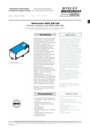
LON Interface MZ2 LON IF<br />
LON interface MZ2 LON IF<br />
Zur Einbindung der Modulzentrale MZ2 in das RWA-LON-BUS System<br />
On incorporating the MZ2 module centre in the SHE-LON-BUS system<br />
Funktion<br />
Über das LON Interface können innerhalb<br />
des MZ2-Systems 7 virtuelle RWA- und<br />
Lüftungsgruppen generiert und über<br />
das LON-Bus System gesteuert werden.<br />
Besonderheiten<br />
• Betriebs- und Störungsanzeige<br />
• 7 RWA- und Lüftungsgruppen<br />
• Integrierte LON Service-Pin Taste<br />
• Schnapp-Montage auf 35 mm<br />
Montageschiene<br />
Function<br />
7 virtual SHE <strong>and</strong> ventilation groups can<br />
be generated via the LON interface within<br />
the MZ2 system <strong>and</strong> controlled by the<br />
LON-bus system.<br />
Special features<br />
• operation display <strong>and</strong> trouble indication<br />
• 7 SHE <strong>and</strong> ventilation groups<br />
• integrated LON Service Pin Switch<br />
• snap-on fitting onto 35 mm mounting rail<br />
Diese Bedienungsanleitung für späteren Gebrauch bzw. Wartung aufbewahren. Please keep these <strong>operating</strong> <strong>instruction</strong> for future reference <strong>and</strong> maintance.<br />
Datei:<br />
Änderungen dienen dem technischen Fortschritt und bleiben vorbehalten. Abbildungen unverbindlich. Subject to technical modifications. Diagram is not binding.<br />
Ti_LON_Interface_dt_engl.indd<br />
Art.Nr. 24999574
2<br />
Anschluss<br />
Hinweis: Für die Grundausstattung wird neben dem<br />
LON Interface Modul eine Master-Control-Unit MZ2 MCU (ab<br />
Version V02.01.00) und das Motormodul MZ2 MM2x8A benötigt.<br />
Die Kommunikation zum LON Netz erfolgt über die virtuellen<br />
Gruppenmodule. Virtuelle Gruppenmodule sind die Gruppenmodule<br />
mit den Adressen 9 bis 15 in der MZ2 PC Software.<br />
Zusätzlich werden 7 virtuelle Motormodule angezeigt (Motormodul<br />
Adresse 9 bis 15 in der MZ2 PC Software). Diese können nicht<br />
angesteuert werden. Im Gegensatz zu den Gruppenmodulen<br />
Typ MZ2 GM können für die virtuellen Gruppenmodule die<br />
Einstellungen für die Sensortypen im PC Programm nicht genutzt<br />
werden. Fehler aus dem MZ2 System werden für verknüpfte RWAund<br />
Meldergruppen an das LON Netzwerk weitergeleitet.<br />
Lüftungs-, Wind/Regen- und Temperatur-Verknüpfungen senden<br />
keine Fehler an das LON Netz. Das Interface Modul kann nicht über<br />
Drehkodierschalter eingestellt werden. Es hat immer die feste<br />
Adresse 66, über die die virtuellen Gruppenmodule angesteuert<br />
werden. Im LON Interface sind 7 virtuelle Gruppenmodule<br />
enthalten. Zur Signalisierung von Fehlern und Betriebszuständen<br />
dienen drei LED’s.<br />
Klemmbelegung<br />
Achtung: Das Interface Modul darf niemals bei<br />
eingeschalteter Versorgung auf die Hutschiene montiert werden,<br />
dies kann zur Zerstörung des Moduls führen.<br />
Klemme A Klemme B<br />
Klemme 1: LON-A1 Klemme 5: LON-B1<br />
Klemme 2: LON-A2 Klemme 6: LON-B2<br />
Klemme 3: 24 V DC Klemme 7: 24 V DC<br />
Klemme 4: GND Klemme 8: GND<br />
�������� ���� ���<br />
�������� ���� ������<br />
�������� ���� ������<br />
�� � � �� � � �� � � �<br />
���� ��<br />
��<br />
�� � � �� � � �� � � �<br />
�� � �� � �� � �<br />
� �� � �� � �� � �<br />
������� �<br />
��������� �<br />
�� � � �<br />
���<br />
��� �� ��<br />
������<br />
������<br />
Connecting<br />
Note: A MZ2 MCU master control unit (from Version<br />
V02.01.00) <strong>and</strong> the MZ2 MM2x8A motor module are required for<br />
the basic equipment, in addition to the LON interface module.<br />
Communications to the LON network are made via the virtual group<br />
modules. Virtual group modules are the group modules with the<br />
addresses 9 to 15 in the MZ2 PC software. In addition, 7 virtual<br />
motor modules are displayed (motor module address 9 to 15 in the<br />
MZ2 PC software). This cannot be activated. Unlike the type MZ2<br />
GM group modules the settings for the sensor types in the PC pro-<br />
gram cannot be used for the virtual group modules. Errors from the<br />
MZ2 system are transmitted to the LON network for linked SHE <strong>and</strong><br />
alarm groups. Ventilation, wind/rain <strong>and</strong> temperature links do not<br />
send errors to the LON network. The interface module cannot be<br />
set by rotary coding switches <strong>and</strong> it always has the fixed address<br />
66 via which the virtual group modules are actuated. The LON inter-<br />
face contains 7 virtual group modules. Three LEDs serve to signal<br />
errors <strong>and</strong> <strong>operating</strong> statuses.<br />
Terminal assignment<br />
Caution: The interface module must never be fitted on<br />
the top hat rail when the supply is switched on, this will lead to<br />
damage to the module.<br />
Terminal A Terminal B<br />
Klemme 1: LON-A1 Klemme 5: LON-B1<br />
Klemme 2: LON-A2 Klemme 6: LON-B2<br />
Klemme 3: 24 V DC Klemme 7: 24 V DC<br />
Klemme 4: GND Klemme 8: GND<br />
������� �<br />
��������� �<br />
�� � �� �<br />
���<br />
��� �� ��<br />
������<br />
������
Bedien- und Anzeigeelemente<br />
Adresswahlschalter<br />
Der Adresswahlschalter wird nicht genutzt. Die Adresse ist auf<br />
einen festen Wert von 66 eingestellt.<br />
LED “OK“ OK<br />
Farbe: Grün, Funktion: Betriebsanzeige.<br />
Led leuchtet, wenn das LON Interface Modul im System<br />
eingebunden ist und über eine gültige Initialisierung verfügt.<br />
Das Modul schaltet die grüne LED erst dann ab, wenn es gültige<br />
Initialisierungsdaten von der MCU erhalten hat. Dies kann bis zu<br />
2 Sek. dauern. Wird das LON Interface nicht regelmäßig von der<br />
MCU angesprochen, erlischt die grüne LED.<br />
LED “Störung“<br />
Farbe: Gelb, Funktion: Störung<br />
Led blinkt, wenn eine Störung vorliegt. Aus dem Blinkrhythmus<br />
kann der bestehende Fehler ermittelt werden. (Siehe hierzu auch:<br />
Tabelle Blinkcode auf Seite 8).<br />
Service PIN Taster<br />
Durch drücken der Service Pin Taste wird vom LON Chip eine<br />
Service PIN Nachricht dieses Knotens in das LON-Netz<br />
gesendet. Diese Nachricht kann genutzt werden um das LON<br />
Interface mit einem Management Tool, wie z. B. ALTO, in ein LON<br />
System einzubinden.<br />
Funktionsbeschreibung<br />
Das LON Interface Modul stellt folgende Funktionen bereit, welche<br />
im Einzelnen durch die PC Software konfiguriert und durch die<br />
Master-Control-Unit MZ2 MCU gesteuert werden. Die bei Selbsttest<br />
und Betrieb erkannten Fehler werden über die LED “Störung“<br />
signalisiert und an das MCU Modul übertragen. Über den Service<br />
Pin kann das LON Interface mit Hilfe eines Management Tools, wie<br />
z. B. ALTO, in ein LON Netz eingebunden werden.<br />
Zur Sicherstellung einer fehlerfreien Kommunikation sind<br />
Verzögerungszeiten zwischen zwei anein<strong>and</strong>erfolgenden<br />
Lüftungsbefehlen vorgesehen. Für RWA-Befehle besteht diese<br />
Notwendigkeit nicht.<br />
Operating elements <strong>and</strong> indicator<br />
Address selector switch<br />
The address selector switch is not used. The address is set to a<br />
fixed value of 66.<br />
LED “OK“ OK<br />
Colour: green, Function: <strong>operating</strong> indicator.<br />
LED alight when the LON Interface module is integradet in the<br />
system <strong>and</strong> has a valid initialisation.<br />
The module does switch off the green LED until it has received va-<br />
lid initialisation data from the MCU. This can take up to 2 seconds.<br />
If the LON interface is not regularly addressed by MCU the green<br />
LED goes out.<br />
LED “Malfunction“<br />
Colour: yellow, Function: malfunction.<br />
The LED flashes if there is a fault. The error that exists can be<br />
determined by the flashing rhythm. (For this see also: Flashing<br />
code table on Page 8).<br />
Service PIN Switch<br />
By pressing the service pin button a service PIN message from this<br />
node is sent by the LON chip to the LON network. This message<br />
can be used to incorporate the LON interface, with a management<br />
tool, e.g. ALTO, into a LON system.<br />
Function description<br />
The LON Interface module provides the following functions that are<br />
individually configured using the PC Software <strong>and</strong> controlled by the<br />
Master-Control-Unit MZ2 MCU. The errors detected in self-test <strong>and</strong><br />
operation are signalled by the “Fault” LED <strong>and</strong> transferred to<br />
the MCU module. The LON interface can be incorporated by the<br />
service pin into a LON network by means of a management tool,<br />
e.g. ALTO.<br />
To ensure error-free communication delay times between two<br />
consecutive ventilation comm<strong>and</strong>s are provided. This requirement<br />
does not exist for SHE comm<strong>and</strong>s.<br />
3
4<br />
Funktionsbeschreibung<br />
Einstellung der Linie und Lüftungsgruppe<br />
In der LON CPU stehen zwei NV (Netzwerk Variable) Arrays für die<br />
Linien- und Lüftungsgruppenzuordnungen zur Verfügung.<br />
In NV Array Gruppen werden die Lüftungsgruppen eingestellt.<br />
7 Elemente stehen für das virtuelle Gruppenmodul zu Verfügung.<br />
Die gleiche Zuordnung wie für die Array Gruppen besteht für die<br />
Array Linien. Dabei ist jeweils das erste Element einer Gruppe<br />
dem ersten virtuellen Gruppenmodul (VGM) zugeordnet. Im MZ2<br />
PC Programm beginnen die virtuellen Module mit der Adresse 9<br />
und enden mit der Adresse 15. Die folgende Tabelle zeigt diesen<br />
Zusammenhang.<br />
Gruppen [i] Linien [i]<br />
VGM1 0 0<br />
VGM2 1 1<br />
VGM3 2 2<br />
VGM4 3 3<br />
VGM5 4 4<br />
VGM6 5 5<br />
VGM7 6 6<br />
In der NV Betriebsart werden verschiedene Betriebsarten der LON<br />
Software eingestellt. Mit den NV’s Line, nviWatchDog und nvo-<br />
WatchDog wird ein virtueller Ring aufgebaut. Jeder Knoten in<br />
diesem Ring sendet zu seinem Nachfolger eine Nachricht und<br />
wartet eine vorgegebene Zeit, ob diese Nachricht wieder bei ihm<br />
ankommt. Wenn nicht wird Fehler 6 angezeigt (siehe Blinkcode<br />
Tabelle, Seite 8). Die Variable nviWatchDog und nvoWatchDog<br />
müssen dazu mit einem Binding verbunden werden. In Linie wird<br />
die Zugehörigkeit für dieses Binding der Knoten eingestellt. Die<br />
folgende Abbildung zeigt diesen Zusammenhang.<br />
������� �� �<br />
����� �� �<br />
������ �� �<br />
����� �� �<br />
Mit der NV RetryToAtmega wird in einem Ringspeicher<br />
eingespeichert wie oft die empfangende Nachricht redundant<br />
gespeichert wird. Dies dient zur Vorbeugung eventuellen Daten-<br />
verlusten bei der Kommunikation zwischen Atmega MCU und<br />
MCU. In der NV Version (St<strong>and</strong>ard Einstellung: 0 x 4900) wird der<br />
Hardware und Software St<strong>and</strong> angegeben.<br />
Das virtuelle Gruppenmodul kann Lüftungs- und RWA-Befehle<br />
empfangen. Die folgende Abbildung zeigt diesen Zusammenhang.<br />
���� ������<br />
���<br />
������������ � � � � � � � � � � � � � � � � � � � � � � � � � �����������<br />
������� �� �<br />
����� �� �<br />
������ �� �<br />
����� �� �<br />
������������ � � � � � � � � � � � � � � � � � � � � � � � � �����������<br />
�������� �� �����������<br />
� ���� �� ����<br />
� ��� �� ������<br />
� ������ �� ����<br />
� ���� ���������� �� ���� ����������<br />
� ������ �� �����<br />
� ������� ��<br />
�����������<br />
Function description<br />
Setting of the line <strong>and</strong> ventilation group<br />
Two NV (network variable) arrays are available in the LON CPU for<br />
the line <strong>and</strong> ventilation group allocations. The ventilation groups<br />
are set in NV array groups. 7 elements are available for the virtual<br />
group module. The same allocation as for the array groups exists<br />
for the array lines. The first element of a group is always assigned<br />
to the first virtual group module (VGM). In the MZ2 PC program the<br />
virtual modules start with address 9 <strong>and</strong> end with address 15. The<br />
following table shows this connection.<br />
group [i] lines [i]<br />
VGM1 0 0<br />
VGM2 1 1<br />
VGM3 2 2<br />
VGM4 3 3<br />
VGM5 4 4<br />
VGM6 5 5<br />
VGM7 6 6<br />
Different modes of the LON software are set in the NV mode. A<br />
virtual ring is built with the NV’s Line, nviWatchDog <strong>and</strong> nvoWatch-<br />
Dog. Each node in this ring sends a message to its successor <strong>and</strong><br />
waits a predetermined time to see whether this message arrives at<br />
the node. If not, error 6 is displayed (see flash code table, Page 8).<br />
The nviWatchDog <strong>and</strong> nvoWatchDog variables must be connected<br />
to a binding for this purpose. The authorisation for this binding of<br />
the nodes is set on line. The following figure shows this connection.<br />
������� �� �<br />
����� �� �<br />
������ �� �<br />
����� �� �<br />
With NV RetryToAtmega it is stored in a ring memory how often the<br />
message received message is redundantly stored. This serves to<br />
prevent any data losses during communication between Atmega<br />
MCU <strong>and</strong> MCU. The hardware <strong>and</strong> software status is displayed<br />
in the NV version (st<strong>and</strong>ard setting: 0 x 4900). The virtual group<br />
module can receive ventilation <strong>and</strong> SHE comm<strong>and</strong>s. The following<br />
figure shows this connection.<br />
������������ � � � � � � � � � � � � � � � � � � � � � � � � �����������<br />
���� ��������<br />
���� �������
Selbsttestfunktionen<br />
Funktionsbeschreibung<br />
Das Modul verfügt über folgende Selbsttestfunktionen:<br />
- Überwachung der eigenen Versorgungsspannung.<br />
- Gültigkeit der Initialisierungsdaten (wird regelmäßig von der<br />
MCU kontrolliert).<br />
- Statuskontrolle (der Status wird regelmäßig vom MCU<br />
Modul kontrolliert).<br />
- RAM-Test bei Start.<br />
- Fehlerfreiheit des Betriebsprogramms über CRC16<br />
Checksummenbildung bei Start und mitlaufend.<br />
- Über Checksumme abgesicherte Kommunikation mit weiteren<br />
Modulen.<br />
Funktionen für das virtuelle Gruppenmodul<br />
Über das virtuelle Gruppenmodul können die folgenden<br />
Funktionen gesteuert werden: Lüftung, RWA und Störung.<br />
Die Überwachung der Sensoren und Bedienstellen werden von<br />
den Knoten im LON Netzt übernommen. Siehe hier zu die<br />
Beschreibung des RWA-LON-BUS Systems.<br />
Es ist zu beachten, dass das LON Netz, im Gegensatz zum MZ2<br />
System, nicht die strickte Trennung zwischen Aktor- und Sensor-<br />
modul vornimmt. Im LON sind die meisten Knoten sowohl Aktor<br />
als auch Sensor. Vom virtuellen Gruppenmodul können die<br />
Funktionen RWA und Lüftung nicht ins LON Netz<br />
gesendet werden. Die Funktionen RWA, Lüftung und Störung<br />
werden vom LON Netz an das virtuelle Gruppenmodul gesendet.<br />
Dieses leitet die Funktionen weiter an die MCU LON. Fehler<br />
werden über die virtuellen Gruppenmodul in das LON Netz<br />
gesendet und vom LON Netz an das LON Interface weitergeben.<br />
Die Fehler werden von der MCU regelmäßig abgefragt.<br />
1. Funktion Lüftung<br />
Funktionen „Lüftung AUF“<br />
Vom LON Netz wird Lüftung “AUF“ an das virtuelle Gruppenmodul<br />
gesendet und diese sendet den Befehl weiter an die MCU. Welche<br />
Aktorausgänge in welcher Art geschaltet werden, hängt von der<br />
Zuordnungstabelle und der Konfiguration der MCU ab.<br />
(Siehe hierzu auch: Beschreibung MCU Modul, PC-Konfigurations-<br />
software). Die St<strong>and</strong>ardfunktion ist: Der zugeordnete Motorkreis<br />
wird in Fahrtrichtung “AUF“ geschaltet. Hierbei werden die<br />
Funktionen: “Umschaltverzögerung“, “Ausgang Freischalten“,<br />
“Ausgangsverzögerung“ und “Lüftungsschrittautomatik vom<br />
Motormodul berücksichtigt (siehe hierzu auch: Beschreibung<br />
Motormodul MZ2 MM2x8A).<br />
Funktionen „Lüftung ZU“<br />
Vom LON Netz wird Lüftung “ZU“ an das virtuelle Gruppenmodul<br />
gesendet und diese sendet den Befehl weiter an die MCU. Welche<br />
Aktorausgänge in welcher Art geschaltet werden, hängt von der<br />
Zuordnungstabelle und der Konfiguration der MCU ab. (Siehe<br />
hierzu auch: Beschreibung Master-Control-Unit MZ2 MCU,<br />
PC-Konfigurationssoftware). Die St<strong>and</strong>ardfunktion ist: Der<br />
zugeordnete Motorkreis wird in Fahrtrichtung “ZU“, geschaltet.<br />
Hierbei werden die Funktionen: “Umschaltverzögerung“, “Ausgang<br />
Freischalten“, “Ausgangsverzögerung“ und “Lüftungsschritt-<br />
automatik“ vom Motormodul berücksichtigt (siehe hierzu auch:<br />
Beschreibung Motormodul MZ2 MM2x8A).<br />
Self test functions<br />
Function description<br />
The module has self-test functions:<br />
- Monitoring of the own supply voltage.<br />
- Validity of initialisation data (is regularly checked by the MCU).<br />
- Status check (the status is checked regularly by the MCU<br />
module.<br />
- RAM test at start.<br />
- Freedom of error of the <strong>operating</strong> program by CRC16 checksum<br />
formation at start <strong>and</strong> when running.<br />
- Communication with further modules assured by checksum.<br />
Functions for the virtual group module<br />
The following functions are controlled by the virtual group module:<br />
ventilation, SHE <strong>and</strong> fault. The sensors <strong>and</strong> control sections are<br />
monitored by the nodes in the LON network. For this see the<br />
description of the SHE-LON-BUS system. It must be borne in mind<br />
that the LON network, unlike the MZ2 system, does not execute<br />
the strict separation between the actuator <strong>and</strong> sensor module. In<br />
the LON most nodes are both actuator <strong>and</strong> sensor. The SHE <strong>and</strong><br />
ventilation functions cannot be sent by the virtual group module<br />
into the LON network. The SHE, ventilation <strong>and</strong> fault functions<br />
are sent by the LON network to the virtual group module. This<br />
transmits the functions to the MCU LON. Errors are sent to the<br />
LON network via the virtual group module <strong>and</strong> are then transmitted<br />
by the LON network to the LON interface. The errors are regularly<br />
requested by the MCU.<br />
1. Function ventilation<br />
Functions „Ventilation OPEN“<br />
Ventilation “OPEN” is sent by the LON network to the virtual group<br />
module, <strong>and</strong> the module transmits the comm<strong>and</strong> to the MCU.<br />
The actuator outputs <strong>and</strong> the types of outputs that are switched<br />
depend on the allocation table <strong>and</strong> the configuration of the MCU.<br />
(For this see also: description of the MZ2 MCU master control unit,<br />
PC configuration software). The st<strong>and</strong>ard function is: The motor<br />
circuit allocated is switched to “OPEN”. In this case the functions:<br />
“Switchover delay”, “Enable output”, “Output delay” <strong>and</strong><br />
“Ventilation step automatic equipment taken into consideration<br />
by motor module” (for this see also: description of MZ2 MM2x8A<br />
motor module).<br />
Functions „Ventilation CLOSED“<br />
Ventilation “CLOSED” is sent by the LON network to the<br />
virtual group module <strong>and</strong> the module transmits the comm<strong>and</strong> to<br />
the MCU. The actuator outputs, <strong>and</strong> which types are switched,<br />
depend on the allocation table <strong>and</strong> the configuration of the MCU.<br />
(For this see also: Description of MZ2 MCU master control unit,<br />
PC configuration software). Te st<strong>and</strong>ard function is: The allocated<br />
motor circuit is switched to “CLOSED”. In this case the functions:<br />
“switchover delay”, “Enable output”, “Output delay” <strong>and</strong><br />
“Ventilation step automatic equipment” are taken into<br />
consideration by the motor module (for this see also: Description<br />
of the MZ2 MM2x8A motor module).<br />
5
6<br />
Funktionsbeschreibung<br />
Funktionen „Lüftung Stopp“<br />
Vom LON Netz wird Lüftung Stop an die virtuelle Gruppenmodule<br />
gesendet und diese senden den Befehl weiter an die MCU. Welche<br />
Aktorausgänge in welcher Art geschaltet werden, hängt von der Zu-<br />
ordnungstabelle und der Konfiguration der MCU ab. (Siehe hierzu<br />
auch: Beschreibung Master-Control-Unit MZ2 MCU, PC-<br />
Konfigurationssoftware).<br />
Funktionen „Lüftung Wind/Regen“<br />
Vom LON Netz wird Lüftung Wind/Regen an die virtuelle Gruppen-<br />
module gesendet und diese senden den Befehl weiter an die MCU.<br />
Die St<strong>and</strong>ardfunktion ist: Wird der Befehl „Rind / Regen“<br />
erkannt, so werden die zugeordneten Klappen / Fenster zu-<br />
gefahren. Es kann für einen zugeordneten Motorkreis eine<br />
Ausgangsverzögerung und eine Umschaltverzögerung aktiviert<br />
sein (siehe hierzu: Beschreibung Motormodul MZ2 MM2x8A). Die<br />
RWA Auslösung hat in jedem Fall Vorrang.<br />
2. Funktionen für automatische Melder<br />
Ergibt sich im LON Netz eine Melderauslösung wird über das LON<br />
Netz RWA Auslösung gesendet und von den virtuellen Gruppen-<br />
modulen an die MCU weitergereicht. Bei einem Melder-Reset wird<br />
RWA-Reset gesendet und von den virtuellen Gruppenmodulen an<br />
die MCU weitergereicht.<br />
3. Funktionen RWA<br />
Funktionen „RWA Auslösung“<br />
Vom LON Netz wird RWA Auslösung an die virtuellen Gruppen-<br />
module gesendet und diese senden den Befehl weiter an die MCU.<br />
Die Funktion des Tasters hängt von der Konfiguration der Anlage<br />
ab (siehe hierzu auch: Beschreibung Master-Control-Unit MZ2<br />
MCU, PC-Konfigurationssoftware). Die St<strong>and</strong>ardfunktion ist: Wird<br />
RWA Auslösung empfangen, so werden die gesteuerten Klappen<br />
aufgefahren. Es kann für einen gesteuerten Motorkreis eine<br />
Ausgangsverzögerung, eine Umschaltverzögerung, ein Nach-<br />
triggern eingestellt sein (siehe hierzu: Beschreibung Motormodul<br />
MZ2 MM2x8A). Des Weiteren kann für einen gesteuerten Motor-<br />
kreis die Funktion „RWA ZU bei Auslösung“ aktiviert sein, dies gilt<br />
sowohl für Motormodule als auch für virtuelle Motormodule. Hiermit<br />
lassen sich Funktionen wie: “Im ausgelösten Br<strong>and</strong>abschnitt<br />
Lüftung auf, alle <strong>and</strong>eren Lüftungen zu“; oder “erst Raffschaltung<br />
der Beschattung starten, dann Fenster/Klappen verzögert öffnen“,<br />
realisieren.<br />
Funktionen „RWA Auf“ bzw. „RWA Reset“<br />
Vom LON Netz wird RWA Reset an die virtuelle Gruppenmodule<br />
gesendet und diese senden den Befehl weiter an die MCU. Die<br />
Funktionen der virtuellen Gruppenmodule hängen von den<br />
Einstellungen in der PC Konfigurationssoftware ab.<br />
Die St<strong>and</strong>ardfunktion ist: Wird RWA Reset empfangen, so werden<br />
die gesteuerten Klappen zugefahren. Dies geschieht nicht, wenn<br />
die Funktion “RWA ZU = nur Auslösung zurücksetzen“ aktiviert ist.<br />
4. Funktionen für Temperatursensor<br />
Diese Funktionalität wird nicht unterstützt.<br />
Functions „Ventilation Stopp“<br />
Function description<br />
Stop ventilation is sent by the LON network to the virtual group<br />
modules <strong>and</strong> these transmit the comm<strong>and</strong> to the MCU. The<br />
actuator outputs <strong>and</strong> the type that are switched depend on the<br />
allocation table <strong>and</strong> configuration of the MCU. (For this see also:<br />
Description of M72 MCU master control unit, PC configuration<br />
software).<br />
Functions „Ventilation Wind/Rain“<br />
Wind/Rain ventilation is sent by the LON network to the virtual<br />
group modules, which transmit the comm<strong>and</strong> to the MCU. The<br />
st<strong>and</strong>ard function is: If the “Wind/Rain” comm<strong>and</strong> is detected, the<br />
allocated flaps / windows are closed. An output delay <strong>and</strong> a<br />
switchover delay can be activated for an allocated motor circuit<br />
(for this see: Description of MZ2 MM2x8A motor module).<br />
The SHE trigger takes priority in each case.<br />
2. Functions for automatic detectors<br />
If an alarm is triggered in the LON network, SHE trigger is sent by<br />
the LON network <strong>and</strong> transmitted by the virtual group modules<br />
to the MCU. In the case of an alarm reset, SHE reset is sent <strong>and</strong><br />
transmitted by the virtual group modules to the MCU.<br />
3. Functions SHE<br />
Functions „SHE Activation“<br />
SHE trigger is sent by LON network to the virtual group modules,<br />
which transmit the comm<strong>and</strong> to the MCU. The function of the key<br />
depends on the configuration of the system (for this see also:<br />
Description of MZ2 MCU master control unit, PC configuration<br />
software). The st<strong>and</strong>ard function is: If SHE trigger is received, the<br />
controlled flaps are opened. An output delay, a switchover delay<br />
<strong>and</strong> retriggering can be set for a controlled motor circuit (for this<br />
see: Description of MZ2 MM2x8A motor module). Furthermore, the<br />
function “RAW OPEN at trigger” can be activated for a controlled<br />
motor circuit; this applies both to motor modules <strong>and</strong> virtual motor<br />
modules. This enables functions such as: “ventilation on in the<br />
triggered fire section, all other ventilation systems closed”; or “first<br />
start shading on circuit, then delayed opening of flaps/windows”, to<br />
be performed.<br />
Functions „SHE OPEN“ alternatively „SHE Reset“<br />
SHE reset is sent by the LON network to the virtual group modules,<br />
which transmit the comm<strong>and</strong> to the MCU. The functions of the<br />
virtual group modules depend on the settings in the PC<br />
configuration software. The st<strong>and</strong>ard function is: If SHE reset is<br />
received, the controlled flaps are closed. This does not happen if<br />
the function “SHE CLOSED = only reset trigger” is activated.<br />
4. Functions for temperature sensor<br />
This functionality is not supported.
Funktionsbeschreibung<br />
5. Funktion „Endmodul am Melder“<br />
Diese Funktionalität wird nicht unterstützt.<br />
6. Funktion für Lüftungsautomatik<br />
Diese Funktionalität wird nicht unterstützt.<br />
7. Funktion „RWA ZU = Reset“<br />
Diese Funktionalität wird nicht unterstützt.<br />
8. RWA ZU: Nur Auslösung zurücksetzen<br />
Diese Funktionalität wird nicht unterstützt.<br />
9. Gruppensteuerung: RWA AUF bei Auslösung<br />
Wird ein Befehl RWA-Taster vom LON Netz an das virtuelle<br />
Gruppenmodul gesendet, so wird der Befehl an die gewählten<br />
Gruppenmodule weitergeleitet. Diese verhalten sich so, als hätten<br />
sie die Auslösung von einem angeschlossenen Taster oder<br />
automatischen Melder erkannt (siehe hierzu auch: Beschreibung<br />
Master-Control-Unit MZ2 MCU, PC Konfigurationssoftware) bzw.<br />
einen entsprechenden Befehl aus dem LON Netz bekommen.<br />
Ein Fehler wird ebenfalls an die gewählten Gruppenmodule<br />
weitergeleitet. Bei virtuellen Gruppenmodulen gilt dies für<br />
verknüpfte RWA- und Meldergruppen. Lüftungs-, Wind/Regen-<br />
und Temperatur-Verknüpfungen senden keine Fehler an das LON<br />
Netz.<br />
10. Gruppensteuerung: RWA ZU für ausgewählte Gruppen<br />
Ist diese Funktion gewählt, so werden alle über die Gruppen-<br />
steuerung (“RWA AUF bei Auslösung“) gesteuerten Klappen /<br />
Fenster beim Tastendruck RWA ZU in Position “ZU“ gefahren.<br />
Hinweis: Falls diese Funktion nicht aktiviert ist, und es wird ein<br />
Tastendruck RWA-ZU erkannt, so werden nur die direkt<br />
gesteuerten Klappen zugefahren, falls nicht die Funktion “RWA ZU<br />
= Nur Auslösung zurücksetzen“ aktiviert ist. Als Folge werden die<br />
durch das Gruppenmodul direkt gesteuerten Klappen / Fenster in<br />
Position “ZU“ gefahren, nicht jedoch die Klappen / Fenster, die<br />
über die Gruppensteuerung mit geöffnet wurden. Diese sind dann<br />
nur von RWA-Bedienstellen des Gruppenmoduls zu schließen,<br />
denen sie direkt zugeordnet sind. In der Regel sollten das die<br />
Taster sein, die sich räumlich im gleichen Br<strong>and</strong>abschnitt<br />
befinden. Ein Fehler wird ebenfalls an die gewählten Gruppen-<br />
module weitergeleitet.<br />
11. Gruppensteuerung: RWA ZU bei Auslösung<br />
Wird ein Befehl RWA-Taster vom LON Netz an das virtuelle<br />
Gruppenmodul gesendet, so wird der Befehl als RWA-ZU an die<br />
gewählten Gruppenmodule weitergeleitet. Diese verhalten sich so,<br />
als hätten sie den Tastendruck RWA-ZU von einem<br />
angeschlossenen Taster erkannt (siehe hierzu auch: Beschreibung<br />
Master-Control-Unit MZ2 MCU, PC Konfigurationssoftware und<br />
Funktionen für RWA Taster: RWA ZU). Ein Fehler wird ebenfalls an<br />
die gewählten Gruppenmodule weitergeleitet.<br />
Function description<br />
5. Function „end module Endmodul at detector“<br />
This functionality is not supported.<br />
6. Operation of the automatic ventilation system<br />
This functionality is not supported.<br />
7. Function „SHE CLOSED = Reset“<br />
This functionality is not supported.<br />
8. SHE CLOSED: Set only activation on reset<br />
This functionality is not supported.<br />
9. Group control: SHE activation when triggering<br />
If an SHE key comm<strong>and</strong> is sent by the LON network to the virtual<br />
group module, the comm<strong>and</strong> is transmitted to the selected group<br />
modules. These behave as if they had detected the trigger from a<br />
connected key or automatic alarm (for this see also: description<br />
of MZ2 MCU master control unit, PC configuration software) or re-<br />
ceived a corresponding comm<strong>and</strong> from the LON network. An error<br />
is also transmitted to the selected group modules. In the case of<br />
virtual group modules this applies to linked SHE <strong>and</strong> alarm groups.<br />
Ventilation, wind/rain <strong>and</strong> temperature links do not send errors to<br />
the LON network.<br />
10. Group control: SHE CLOSED for selected groups<br />
If this function is selected, all flaps / windows controlled by the<br />
group control (“SHE OPEN when triggering“) are moved to the<br />
“CLOSED” position the SHE CLOSED key is pressed. Note: If this<br />
function is not activated, <strong>and</strong> if the pressing of the SHE-CLOSED<br />
key is detected, only the directly controlled flaps are closed if the<br />
function “SHE CLOSED = Only reset trigger” is not activated.<br />
Consequently the flaps / windows controlled directly by the group<br />
module are moved to the “CLOSED” position, but not the flaps /<br />
windows which have also been opened by the group control. The-<br />
se must then only be closed by SHE control sections of the group<br />
module to which they are directly assigned. These should<br />
generally be the keys which are located spatially in the same<br />
fire section. An error is also transmitted to the selected group<br />
modules.<br />
11. Group control: SHE CLOSED on triggering<br />
If an SHE key comm<strong>and</strong> is sent by the LON network to the virtual<br />
group module, the comm<strong>and</strong> is transmitted as SHE CLOSED to<br />
the selected group modules. These behave as if they had detected<br />
the press of an SHE CLOSED from a connected key (for this see<br />
also: Description of MZ2 MCU master control unit, PC<br />
configuration software <strong>and</strong> functions for SHE key: SHE CLOSED).<br />
An error is also transmitted to the selected group modules.<br />
7
8<br />
Funktionsstörung<br />
Fehlerbeh<strong>and</strong>lung und Weiterleitung<br />
Fehler, die im MZ2 System erscheinen werden an das LON Netz<br />
weitergeleitet, wenn RWA- oder Meldergruppen verknüpft sind.<br />
Lüftungs-, Wind/Regen- und Temperatur-Verknüpfungen senden<br />
keine Fehler an das LON Netz. Akku und 230 V Netz Fehler werden<br />
an alle Linen im LON Netz gesendet.<br />
Blinkcode Tabelle<br />
Erkannte Fehler werden als Blinkfolge über die gelben Störungs-<br />
LED‘s ausgegeben. L = Wird der Blinkcode durch ein langes Blink-<br />
signal eingeleitet, so stammt der Fehler von einem <strong>and</strong>eren Modul.<br />
Die Blinkfolgen haben folgende Bedeutung:<br />
Blinkfolge<br />
Flash Code<br />
DAUER<br />
DURATION<br />
1<br />
6<br />
8<br />
10<br />
11<br />
12<br />
L+2<br />
L+6<br />
AUS<br />
OFF<br />
Fehler<br />
Error<br />
Initdaten<br />
Initdata<br />
Netzfehler<br />
Mains failureInitdata<br />
Busfehler<br />
Bus error<br />
Selbsttest<br />
Self test<br />
Versorgung +5 V<br />
Supply +5 V<br />
Versorgung +24 V<br />
Supply +24 V<br />
Melder Kurzschluss<br />
Short-circuit of detector<br />
Netzmodulfehler (NM)<br />
Error of the power pack (NM)<br />
LON Fehler<br />
Error of LON<br />
kein Fehler<br />
no error<br />
Auslöser<br />
Cause of Error<br />
Failure malfunction<br />
Error h<strong>and</strong>ling <strong>and</strong> transmission<br />
Errors which occur in the MZ2 system are transmitted to the LON<br />
network if SHE or alarm groups are linked. Ventilation, wind/rain<br />
<strong>and</strong> temperature links send no errors to the LON network. Battery<br />
<strong>and</strong> 230 V mains errors are sent to all lines in the LON network.<br />
Flashing code chart<br />
Errors recognised are emitted as a flashing sequence via the yellow<br />
LEDs fault. L = If the flashing codes is introduced by a long<br />
flashing signal, then the fault originates from another module.<br />
The flashing codes have the following meanings:<br />
Initialisierungsdaten fehlen oder Prozessor läuft nicht<br />
Initialisation data missimg or processor not running<br />
Netzspannung fehlt (Notbetrieb)<br />
Mains voltage missing (emergency operation)<br />
Kommunikation mit der CPU gestört<br />
Communication with the CPU disrupted<br />
Programmüberwachung<br />
Program monitoring<br />
int. Versorgungsspannung +5 V fehlerhaft<br />
int. supply voltage +5 V faulty<br />
int. Versorgungsspannung +24 V fehlerhaft<br />
int. supply voltage +24 V faulty<br />
Kurzschluss im Melderkreis<br />
Short-circuit of detector circuit<br />
Fehler im Netzmodul<br />
Error of the power pack<br />
Ein Knoten aus dem LON Netz hat einen Fehler übermittelt<br />
Ein Knoten aus dem LON Netz hat einen Fehler übermittelt<br />
---
Fehler<br />
Funktionsstörung<br />
Diese Liste beinhaltet einige typische Fehler und beschreibt das<br />
geeignete Vorgehen für ihre Behebung. Nicht alle mögliche<br />
Fehler können automatisch erfasst werden, daher ist eine<br />
regelmäßige Prüfung und Wartung der Anlage unumgänglich.<br />
Netzfehler<br />
Dieser Fehler wird signalisiert, wenn an einem Netzteilmodul keine<br />
230 V Netzspannung anliegt. Abhilfe:<br />
- Siehe Fehler im Netzteilmodul.<br />
Busfehler<br />
Die Kommunikation mit dem MCU Modul ist gestört. Abhilfe:<br />
- Prüfen, ob der Adresswahlschalter auf der richtigen Adresse<br />
steht.<br />
- Prüfen, ob das Modul richtig auf der Schiene und auf den Bus-<br />
steckern eingeschnappt ist.<br />
- Prüfen, ob die Busverbinder auf der Hutschiene in Ordnung sind.<br />
- Ca. 5 Minuten abwarten, ob die MCU die Kommunikation neu<br />
initialisiert.<br />
- Falls der Fehler länger als 5 Minuten anhält, auf dem MCU-<br />
Modul einen Anlagenreset auslösen.<br />
- Falls nichts hilft, Modul austauschen.<br />
Selbsttest<br />
Der Mitlaufende Selbsttest hat einen Fehler im Programm<br />
festgestellt. Abhilfe:<br />
- Das Modul zum Service einschicken.<br />
gewährleistet.<br />
Achtung: Ein sicherer Weiterbetrieb ist nicht<br />
Versorgung +5 V<br />
Der mitlaufende Selbsttest hat einen internen Fehler festgestellt.<br />
Abhilfe:<br />
- Das Modul zum Service einschicken.<br />
gewährleistet.<br />
Achtung: Ein sicherer Weiterbetrieb ist nicht<br />
Versorgung +24 V<br />
Der mitlaufende Selbsttest hat eine fehlerhafte Versorgungs-<br />
spannung festgestellt. Abhilfe:<br />
- Sicherungen am Netzteilmodul überprüfen.<br />
- Prüfen, ob das Modul richtig auf der Schiene eingeschnappt ist.<br />
- Prüfen, ob die Busverbinder auf der Hutschiene in Ordnung sind.<br />
- Prüfen, ob die Verdrahtung Hutschiene zu Netzmodul in Ordnung<br />
ist.<br />
- Falls nichts hilft, Modul austauschen.<br />
Fehler im Netzteilmodul<br />
Dieser Fehler zeigt an, dass auf einem Netzteilmodul ein Fehler<br />
auftritt. Die Fehlerursache wird auf dem Netzteilmodul selber<br />
signalisiert. Abhilfe:<br />
- Nachsehen welcher Blinkcode auf dem Netzteil signalisiert wird,<br />
den Fehler dort beheben.<br />
LON Fehler<br />
Im LON Netz den Fehler lokalisieren und beheben.<br />
Error<br />
Failure malfunction<br />
This list contains some typical errors <strong>and</strong> describes a suitable<br />
procedure for rectification. Not all possible faults can be collated<br />
automatically, regular inspection <strong>and</strong> maintenance of the system<br />
is therefore necessary.<br />
Network errors<br />
This error is signalled if no 230 V mains voltage is applied to a<br />
power pack module. Remedy:<br />
- See errors in the power pack module.<br />
Bus error<br />
Communication with the MCU module is disrupted.<br />
Remedial measures:<br />
- Check if the address selector switches are on the correct<br />
address.<br />
- Check that the module are snapped onto the rail correctly.<br />
- Check that the bus connector on the top hat rail is ok.<br />
- Wait for approx. 5 minutes, in case the MCU module initialises<br />
the communication again.<br />
- If the error lasts for longer than 5 minutes, trigger a system reset<br />
on the MCU module.<br />
- If nothing helps replace the module.<br />
Self test<br />
The continuous self test has discovered an error in the program.<br />
Remedial measures:<br />
- Send the module into the service department.<br />
guaranteed!<br />
Supply +5 V<br />
Warning: Further safe operation can no longer be<br />
The continuous self test has discovered an internal error.<br />
Remedial measures:<br />
- Send the module into the service department.<br />
guaranteed!<br />
Warning: Further safe operation can no longer be<br />
Supply +24 V<br />
The continuous self test has discovered an internal error.<br />
Remedial measures:<br />
- Check fuses on the power supply unit.<br />
- Ckeck that the module is snapped onto the rail correctly.<br />
- Check that the bus connector on the top hat rail is ok.<br />
- Check if the wiring top hat rail to power supply unit is ok.<br />
- If nothing helps replace the module.<br />
Errors in the power pack module<br />
This error indicates that an error has occurred in a power pack<br />
module. The cause of the error is signalled on the power pack<br />
module itself. Remedy:<br />
- Check the flash code that is signalled on the power pack <strong>and</strong><br />
remove the error there.<br />
LON errors<br />
Locate the fault in the LON network <strong>and</strong> remove it.<br />
9
10<br />
Technische Daten<br />
Betriebsspannung des Moduls: 15 - 32 V DC<br />
Stromaufnahme des Moduls: 13 mA (bei 27,5 V<br />
Betriebsspannung, ohne<br />
Sensorversorgung)<br />
Leistungsaufnahme: 0,36 VA (bei 27,5 V<br />
Betriebsspannung, ohne<br />
Sensorversorgung)<br />
Stromaufnahme im<br />
Notbetrieb: 13,0 mA (bei 27,5 V<br />
Betriebsspannung, ohne<br />
Sensorversorgung)<br />
Leistungsaufnahme im<br />
Notbetrieb: 0,36 VA (bei 27,5 V<br />
Betriebsspannung, ohne<br />
Sensorversorgung)<br />
Temperaturbereich: 0 - 50 °C<br />
Feuchtigkeitsbereich: 10 – 75 % rel. Feuchte<br />
Betauung nicht zulässig<br />
Schutzklasse: (Bestimmt durch<br />
MZ2 Aufbau)<br />
Abmessungen (ohne Klemmen): 100 x 22 x 113 mm<br />
(H x B x T)<br />
Montageart: Schnapp-Montage auf<br />
35 mm Miontageschiene<br />
mit Busklemmen<br />
<strong>Technical</strong> data<br />
Module <strong>operating</strong> voltage: 15 - 32 V DC<br />
Module power consumption: 13 mA (at 27.5 V<br />
<strong>operating</strong> voltage,<br />
without sensor supply)<br />
Power consumption: 0.36 VA (at 27.5 V<br />
<strong>operating</strong> voltage,<br />
without sensor supply)<br />
Current consumption emergency<br />
operation: 13,0 mA (at 27.5 V<br />
<strong>operating</strong> voltage,<br />
without sensor supply)<br />
Power consumption emergency<br />
operation 0,36 VA (at 27.5 V<br />
<strong>operating</strong> voltage,<br />
without sensor supply)<br />
Temperature range: 0 - 50 °C<br />
Humidity Range: 10 - 75 % rel. humidity,<br />
moisture not permitted<br />
Protection degree: (detemined by MZ2<br />
set up)<br />
Dimensions (without clamps): 100 x 22 x 113 mm<br />
(h x w x d)<br />
Mounting: snap-on fitting onto 35<br />
mm mounting rail with<br />
bus terminals