Brushless DC-Motors Bürstenlose ... - Dunkermotoren
Brushless DC-Motors Bürstenlose ... - Dunkermotoren
Brushless DC-Motors Bürstenlose ... - Dunkermotoren
- Keine Tags gefunden...

Sie wollen auch ein ePaper? Erhöhen Sie die Reichweite Ihrer Titel.
YUMPU macht aus Druck-PDFs automatisch weboptimierte ePaper, die Google liebt.
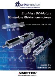
<strong>Brushless</strong> <strong>DC</strong>-<strong>Motors</strong>Bürstenlose GleichstrommotorenDIN EN ISO 9001:2008DIN EN ISO 14001:2004Series BGBaureihe BG
Foreword / VorwortTo Our Valued Customers,<strong>Dunkermotoren</strong> is a world class leader in high qualitymotion control solutions to meet the ever increasingdemands for cost effective and reliable drive solutions.Our comprehensive product range offers the flexibilityto provide customized solutions as well as standardizedcomponents.The catalog represents <strong>Dunkermotoren</strong>´s years ofengineering excellence.The <strong>Dunkermotoren</strong> Team will continue to utilize ouroutstanding engineering and industrial capabilities to meetthe requirements helping you to succeed.Wishing you great success in your business.Nikolaus GräfGeneral ManagerLiebe Kunden,als führender Hersteller der Antriebstechnik bieten wirIhnen wirtschaftliche, effiziente und qualitativ hochwertigeKomplettlösungen.Unser umfassendes Produkt- und Leistungsspektrumermöglicht Ihnen ein hohes Maß an Flexibilität: Obstandardisierte Komponenten oder kundenspezifischeAnforderungen – bei uns finden Sie garantiert diepassende Lösung.Mit diesem Katalog können Sie sich einen Überblicküber unsere innovativen und richtungsweisenden Produkteverschaffen.Das <strong>Dunkermotoren</strong>-Team berät Sie gerne engagiert undkompetent. Denn: Ihr Erfolg ist unser Ziel.In diesem Sinne freuen wir uns auf Sie und wünschenIhnen alles Gute.Ihr Nikolaus GräfGeneral Manager2
Content / Inhalt2 Foreword / Vorwort3 Content / Inhalt4 Why <strong>Dunkermotoren</strong>? / Gute Gründe6 Our Product Range / Unser modulares Lieferprogramm7 Applications / Anwendungen8 <strong>Brushless</strong> <strong>DC</strong> <strong>Motors</strong> BG / Bürstenlose Gleichstrommotoren BG9 BG Selection Guide / BG-Auswahlübersicht10 Technical Information / Technische Informationen11 Engineering Reference / Auslegung des Antriebs12 Motor BG 32 / BG 32 KI 10 - 20 W14 Motor BG 42 / BG 42 KI 40 - 65 W16 Controller / Regelelektronik BGE 42 / BGE 3004A18 Motor BG 44 SI 20 - 40 W21 Overview BG 45 / Übersicht BG 4522 Motor BG 45 SI 40 - 75 W24 Motor BG 45 PI 40 - 75 W26 Motor BG 45 CI/PB/EC 40 - 75 W30 Motor BG 45 MI 40 - 75 W33 Overview BG 65 / Übersicht BG 6534 Motor BG 65 50 - 150 W36 Motor BG 65 KI 50 - 220 W38 Motor BG 65 SI 50 - 150 W40 Motor BG 65 PI 50 - 150 W42 Motor BG 65 CI/PB/EC 50 - 150 W46 Motor BG 65 MI 50 - 150 W49 Overview BG 75 / Übersicht BG 7550 Motor BG 75 220 - 530W52 Motor BG 75 SI 220 - 450W54 Motor BG 75 PI 220 - 450W56 Motor BG 75 CI/PB/EC 220 - 450W60 Motor BG 75 MI 220 - 450W62 Controller / Regelelektronik BGE 3508 / 600564 Controller / Regelelektronik BGE 3515 / 601066 Controller / Regelelektronik BGE 605068 Controller / Regelelektronik BGE 3010071 Gateway CANopen Profibus73 Gears / Getriebe74 Planetary gearboxes / Planetengetriebe92 Worm gearboxes / Schneckengetriebe100 Brakes for BL<strong>DC</strong> <strong>Motors</strong> / Bremsen für BG-Motoren102 Incremental Encoders for BL<strong>DC</strong> <strong>Motors</strong> / Inkrementalgeber für BG-Motoren104 Absolute encoder for BL<strong>DC</strong> motors / Absolutwertgeber für BG-Motoren105 Accessories / Zubehör114 Representatives and Distributors / Vertretungen© 11/2011<strong>Dunkermotoren</strong> GmbHPrinted in Germany3
Why <strong>Dunkermotoren</strong>? / Gute GründeTechnology & Customer FocusAt <strong>Dunkermotoren</strong>, research and developmentis a way of life. The company is activelycommitted to develop key technologies andproducts that are crucial for its growth. Nextgenerationtechnology is in the R&D pipelinetoday.Product development is focused on innovationsto help our customers create value anddifferentiate themselves from competitors.Innovation und Kundenorientierung<strong>Dunkermotoren</strong> ist stolz darauf, vielfach neueIndustrie-Standards in der Antriebsbranchegeschaffen zu haben. Es ist der Ansprucheines Technologieführers, der Konkurrenzimmer einen entscheidenden Schritt vorauszu sein.Unsere innovativen marktorientiertenAntriebslösungen machen unsere Kundennoch erfolgreicher und helfen ihnen, sichmit ihren Produkten positiv von denen derMitbewerber abzusetzen.Quality Assurance & ReliabilityOne of <strong>Dunkermotoren</strong>´s primary objectivesis to offer outstanding quality.In 1991 <strong>Dunkermotoren</strong> became the world´sfirst manufacturers of small motors to becertified to ISO 9001. In the meantime,<strong>Dunkermotoren</strong> has won numerous qualityawards.<strong>Dunkermotoren</strong> regards quality as a comprehensiveprocess involving all activities in thefactory. Our products are manufactured inGermany and China on highly automatedproduction lines. Failure mode and effectsanalysis during design and development,and fully automated testing integrated in theproduction line ensure a uniformly high levelof quality.Qualität & ZuverlässigkeitAntriebslösungen höchster Qualität sind bei<strong>Dunkermotoren</strong> eine Selbstverständlichkeit,fest verankert in Unternehmensgrundsätzenund Philosophie. Bereits 1991 wurde <strong>Dunkermotoren</strong>als weltweit erster Hersteller vonKleinmotoren nach ISO 9001 zertifiziert. Inder Zwischenzeit folgten zahlreiche weitereAuszeichnungen und Zertifizierungen vonKunden und Vereinigungen.<strong>Dunkermotoren</strong> versteht Qualität als einenganzheitlichen Prozess, der sämtliche betrieblicheTätigkeiten umfasst.<strong>Dunkermotoren</strong> produziert in Deutschland undChina; hochautomatisierte Fertigungsstreckenund vollautomatische Qualitätskontrollen inden Fertigungslinien gewährleisten einkonstant hohes Qualitätsniveau.Flexibility, Delivery Performance &Complete Motion SolutionsStandardized motors, gears and modularaccessories are available with a higher degreeof flexibility to address specific requirementsin complete motion solutions. For thecustomer, this means better control of quality,reduced inventory and reduced productiontime. If any detail does not entirely meet yourrequirements, our R&D department will makemodifications at short notice.<strong>Dunkermotoren</strong>’s Modular System anoptimized logistics, enables prompt deliveryfor both stock and customized products.Delivery time for stock items is 2-5 days andfor customized solutions is 3-7 weeks.Flexibilität, Lieferperformance undumfassende AntriebslösungenDie Produktpalette von <strong>Dunkermotoren</strong> istso aufgebaut, dass sich mit standardisiertenMotoren und einem modular aufgebautenZubehör eine hohe Flexibilität für umfassendeAntriebslösungen ergibt. Und sollten Sieeinmal ein Produkt benötigen, das es nochnicht gibt, dann entwickelt unsereKonstruktionsabteilung kundenspezifischeSonderlösungen in kürzester Zeit.Aufgrund der konsequenten Verwirklichungdes Baukastensystems und einer ausgeklügeltenProduktionslogistik bietet <strong>Dunkermotoren</strong>eine bessere Lieferperformance alsdie meisten Mitbewerber, bei Lagerprodukten(Ø 2-5 Tage) wie auch bei kundenspezifischenLösungen (Ø 3-7 Wochen).4
Service & ProximityWhether home or abroad, <strong>Dunkermotoren</strong>´smulti-lingual customer service advisers arealways on hand. By worldwide local presenceof <strong>Dunkermotoren</strong> individual responsibility isgiven to the interests of the trading partners- the best drive solution and the most economicalapplication.Today and in the future, <strong>Dunkermotoren</strong> willprovide a total service to the customers -wherever they are.Service & KundennäheOb im In- oder Ausland, die Kundenberatervon <strong>Dunkermotoren</strong> sind immer vor Ortpräsent und sprechen die Sprache desKunden.Zur bestmöglichen Berücksichtigung derInteressen des Kunden werden individuelleSchulungen, Betreuung und Beratung durchunsere hochkompetenten Account Managergewährleistet.In der Technik wie auch im Vertrieb - dieMitarbeiter von <strong>Dunkermotoren</strong> scheuenkeine Herausforderung, Ihre Anforderungenund Wünsche sind Maßstab für Denken undHandeln.Sustainable Development<strong>Dunkermotoren</strong> is fully aware of its role topromote sustainable development. Thereforeit commits itself to pay particular attention tothe environment conservation while selectingand using efficiently raw materials and energynecessary for production, supply and use ofthe product.In 2002 <strong>Dunkermotoren</strong> has introduced theenvironmental management systemconforming to the standard ISO 14001.Umweltschutz und nachhaltigeEntwicklung<strong>Dunkermotoren</strong> ist sich seiner Rolle,nachhaltige Entwicklung zu fördern,bewusst. Deshalb hat sich die Firma demUmweltschutz verpflichtet. Ressourcenwerden sparsam und effizient eingesetzt.Als erster Hersteller von Elektrokleinmotorenerhielt <strong>Dunkermotoren</strong> im Jahre 2002 dieUmweltmanagementauszeichnung nachDIN EN ISO 14001.Therefore / Darum5
Our Product Range / Unser modulares Lieferprogramm<strong>DC</strong>-<strong>Motors</strong>Gleichstrommotoren<strong>Brushless</strong> <strong>DC</strong> <strong>Motors</strong>, Series BGBürstenlose Gleichstrommotoren, Baureihe BGRated voltage 12-360 V<strong>DC</strong> Nennspannung 12-360 V<strong>DC</strong>Rated speed 2300-4050 rpm Nenndrehzahl 2300-4050 min -1Torque 2.6-150 Ncm Drehmoment 2,6-150 NcmPower rating 10-530 W Abgabeleistung 10-530 W<strong>DC</strong> <strong>Motors</strong>, Series GR/GGleichstrommotoren, Baureihe GR/GRated voltage 3-220 V<strong>DC</strong> Nennspannung 3-220 V<strong>DC</strong>Rated speed 1500-10000 rpm Nenndrehzahl 1500-10000 min -1Torque 0.47-65 Ncm Drehmoment 0,47-65 NcmPower rating 3-240 W Abgabeleistung 3-240 WAC-<strong>Motors</strong>WechselstrommotorenAC <strong>Motors</strong>, Series KD/DRDreh- u. Wechselstrommotoren, Baureihe KD/DRRated voltage 230-400 VAC, 50Hz Nennspannung 230-400 VAC, 50HzPower rating 5-86 W Abgabeleistung 5-86 WTorque 3.6-31.5 Ncm Drehmoment 3,6-31,5 NcmVariants 2/4 pole Varianten 2/4 poligVenetian Blind- and Positioning Drives, Series D Jalousie- und Stellantriebe, Baureihe DRated voltage 230 VAC, 50 Hz Nennspannung 230 VAC, 50 HzRated speed 11-52 rpm Nenndrehzahl 11-52 min -1Torque 3-20 Nm Drehmoment 3-20 NmPower rating 50-220 W Abgabeleistung 50-220 WAccessoriesAnbautenPlanetary Gearboxes, Series PLGPlanetengetriebe, Baureihe PLGContinuous torque 0.3-160 Nm Dauerdrehmoment 0,3-160 NmRatio 4:1-710:1 Untersetzungsverhältnis 4:1-710:1Worm Gearboxes, Series SGSchneckengetriebe, Baureihe SGContinuous torque 1-30 Nm Dauerdrehmoment 1-30 NmRatio 5:1-80:1 Untersetzungsverhältnis 5:1-80:1Brakes, Series EEncoders, Series RE/TG/MEElectronic Control Systems, Series BGE/RSBremsen, Baureihe EInkrementalgeber, Baureihe RE/TG/MERegelelektroniken, Baureihe BGE/RS6
Applications / AnwendungenSome ApplicationsIndustrial Automationwood machineryprinting industrypaper industrytextile industryfood & beverage machinerypackaging machinerysemiconductor industryplastics industrymaterial handlingmechanical handlingMedical devices & laboratory equipmentDoor automationSun protectionMotiveBeispiele für AnwendungenIndustrielle AutomatisierungHolzbearbeitungDruckindustriePapierindustrieTextilmaschinenLebensmittelmaschinenVerpackungsmaschinenHalbleiterindustrieKunststoffherstellungMaterialhandlingLager und FördertechnikMedizin- und LabortechnikTürautomationSonnenschutzMotiveCustomized SolutionsThe impossible takes a little longer - customer specificsolutions from <strong>Dunkermotoren</strong>!Take advantage of the full range of knowledge and experienceof our drive specialists.We will develop the best possible drive unit solution for you- innovative, objective and application-oriented.Kundenspezifische LösungenGeht nicht gibt´s nicht - Kundenspezifische Lösungenvon <strong>Dunkermotoren</strong>!Profitieren Sie vom Know-how des Antriebsspezialisten.Wir realisieren zielgerichtet, innovativ und anwendungsorientiertdie bestmögliche Antriebseinheit für Sie.7
<strong>Brushless</strong> <strong>DC</strong> <strong>Motors</strong> BGBürstenlose Gleichstrommotoren BGThe <strong>Dunkermotoren</strong> BG range of brushless, direct currentmotors (EC motors) are notable for:• Very long life• High efficiency• Highly dynamic acceleration• Good regulation characteristics• Wide speed range• High power density• Maintenance-free• Robust design• Integral Hall sensors for rotor position• Low moment of inertia• High degree of protection (up to IP65)• Motor insulation - Class E• Neodymium magnetsDie bürstenlosen Gleichstrommotoren von <strong>Dunkermotoren</strong>(EC-Motoren) der Baureihe BG zeichnen sich aus durch:• Sehr hohe Lebensdauer• Hoher Wirkungsgrad• Hochdynamische Beschleunigung• Gute Regelbarkeit• Großer Drehzahlbereich• Hohe Leistungsdichte• Wartungsfreiheit• Robusten Aufbau• Integrierten Hallsensoren zur Erfassung der Rotorlage• Geringes Trägheitsmoment• Hohe Schutzart (bis IP65 möglich)• Motor nach Isolierstoffklasse E• NeodymmagneteThese electronically-commutated <strong>DC</strong> motors can becombined with control electronics, gearboxes, andencoders in a modular system to provide a flexible,adaptable, market-oriented solution.You will find further technical information,layout data, and information on the selection of motorsand gearboxes on page 10, and on the Internet atDie elektronisch kommutierten Gleichstrommotorenergeben im Baukastensystem zusammen mit Regelelektroniken,Getrieben, Bremsen und Istwertgebern einflexibles, anpassungsfähiges und marktorientiertesSortiment.Weitere technische Informationen, Auslegungen undInformationen zur richtigen Auswahl von Motoren undGetrieben erhalten sie auf S. 10 und im Internet beiwww.dunkermotoren.comwww.dunkermotoren.de8
BG Selection GuideBG-Auswahlmöglichkeiten32x1032x2042x1542x3044x2544x5045x1545x3065x2565x5065x7575x2575x5075x75<strong>Motors</strong> without controllerMotoren ohne ElektronikKISIPICIPBECCommutation ControlSpeed ControlPositioning ControlInterfaceInterfaceInterfaceMI Master integratedController attachedRegelelektronik angebautBGE 42/3004A 16BGE 3508 / 6005* 62BGE 3515 / 6010* 64BGE 6050* 66BGE 30100 68W 10 20 40 65 20 40 40 75 60 100 140 250 400 530Ncm 3 5 11 18 6 11 13 22 20 30 40 66 110 150Page/Seite 12 12 14 14 18 18 21 21 33 33 33 49 49 4970RE 20 102RE 30 102RE 56 102ME integrated 102AE65 Absolut Encoder 104PLG 32 (0.40 - 4 Nm) 74PLG 32 H (0.40 - 4 Nm) 76PLG 42 K (0.70 - 3 Nm) 78PLG 42 S (3.5 - 14 Nm) 80PLG 52 (1.2 - 24 Nm) 82PLG 52 H (1.2 - 24 Nm) 84PLG 60 (5 - 25 Nm) 86PLG 63 (5 - 100 Nm) 88PLG 75 (25 - 160 Nm) 90SG 45 (0.25 - 0.75 Nm) 92SG 62 (1 - 1.5 Nm) 94SG 80 (2 - 8 Nm) 96SG 120 (8 - 30 Nm) 98E 38 R 100E 46 A 100E 90 R 100E 100 R/A 100E 300 R/A 100Miscellaneous / Verschiedenes 105ELECTRONIC CONTROL SYSTEMS / REGELELEKTRONIKENEXTERNAL CONTROLLER / EXTERNE REGELELEKTRONIKENGateway CANopen Profibus / Gateway CANopen ProfibusINCREMENTAL ENCODERS / INKREMENTALGEBERGEARBOXES / GETRIEBEBRAKES / BREMSENACCESSORIES / ZUBEHÖR* For motors with Hall sensors and incremental encoder RE 30 attached / * Für Motoren mit Hallsensoren und angebauten Inkrementalgeber RE 30n Standard / Standard n On request / auf Anfrage9
Technical Information / Technische InformationPERFORMANCE DATAPerformance figures given in the tables are measured in accordancewith EN60034. These figures are based on the assumption that themotor is freestanding and that certain other theoretical conditions arefulfilled. In a real application, the rated torque of a motor will often beconsiderably higher. For this reason, the data tables quote the ratedtorque measured according to N (lower value) and also the torque withthe motor mounted on a thermally conducting steel plate with thedimensions 105 x 105 x 10 mm (value in brackets).LEISTUNGSDATENIn den Datentabellen sind die Werte gemessen nach EN60034angegeben. Diese Werte basieren auf der Annahme eines freistehenden<strong>Motors</strong> und auf weiteren theoretischen Gegebenheiten. Im reellenEinsatzfall liegt das Nenndrehmoment des <strong>Motors</strong> oftmals wesentlichhöher. Deshalb sind in den Datentabellen die Nenndrehmomentegemessen nach EN (niedrigere Angabe) sowie gemessen beiAnbringung einer thermisch leitenden Stahlplatte der Größe105 x 105 x 10 mm (Angabe in Klammern) aufgeführt.For many applications, it issufficiently accurate to takethe most important datafrom the motor characteristicdiagrams and data tables.Although tolerances andtemperature influences arenot taken into account, thedata is accurate enough forapproximate calculations.The degree of protectionquoted relates only to thehousing – adequate sealingof the shaft is theresponsibility of thecustomer.current/Strom I (A)2.82.421.61.20.80.40efficiency/Wirkungsgrad η (%)706050403020100rated speed/Drehzahl n (rpm)700060005000 N = f (M)400030002000ηContinuous operationDauerbetriebCyclic operationZyklischer BetriebDestroying operationZerstörende BetriebszuständeJ = f (M)10000-0.8 0 0.8 1.6M2.4 N 3.2 4 4.8 5.6 6.4 7.2 8 NcmDen Motordiagrammen und Datentabellenkönnen die für vieleAnwendungen wichtigsten Datenentnommen werden. ObwohlToleranzen und Temperatureinflüssenicht berücksichtigt sind, reichendie Werte für überschlagsmässigeBetrachtungen aus. Die angegebenenSchutzarten beziehen sich nur auf dieGehäuse. Die Abdichtung der Welle istvom Kunden vorzunehmen.- Nominal voltage U N(V<strong>DC</strong>)The <strong>DC</strong> voltage that is applied to the commutation electronics as asystem supply voltage. All rated data in our catalogs are withreference to this voltage. Motor applications are, however, notrestricted to this voltage.- Rated torque M N(Ncm)The torque that can be produced by the motor, operating continuously,in an ambient temperature of 20°C.- Rated speed n N(min -1 )The speed of the motor when it is operating at rated torque (6).- Rated current I N(A)The current drawn from a <strong>DC</strong> source when the motor is operating atrated torque (7).- Starting current I A(A)The current required to produce the starting torque. For motors withelectronics, the starting current may be higher than the permissiblepeak current (4).- Starting torque M A(Ncm)The maximum torque the motor can produce (2).- Rated power P N(W)The output power which the motor can produce continuously; it iscalculated from rated speed and rated torque.- Moment of inertia of rotor J R(gcm 2 )The moment of inertia of the rotor is the factor that determines thedynamic properties of a motor.- Peak current I max(A)The maximum current for electronics or motors with integralelectronics (5).- Max. permissible voltage range U max(V<strong>DC</strong>)The minimum and maximum permissible input voltage for electronicsor motors with integral electronics.- Recommended speed control range n max(min -1 )The regulated speed range within which rotor position sensing by Hallsensors ensures a smooth torque curve. As a rule, this range can beextended by installing a rotary encoder.The data in this catalog contain product specifications, but are not aguarantee of particular properties. The stated values are subject totolerances. Any supplementary information and safety instructions givenin the operating manual must be observed with no exceptions. Wereserve the right to make technical changes and to restrict availability.- Nennspannung U N(V<strong>DC</strong>)Die Gleichspannung, die als Systemversorgungsspannung an dieKommutierungselektronik angelegt wird. Auf diese Spannung beziehensich alle Nenndaten in den Katalogen. Die Motoranwendung ist jedochnicht auf diese Spannung beschränkt.- Nenndrehmoment M N(Ncm)Das Moment, das der Motor bei einer Umgebungstemperatur von20°C im Dauerbetrieb abgeben kann.- Nenndrehzahl n N(min -1 )Die Drehzahl, die sich bei Abgabe des Nenndrehmoments einstellt (6).- Nennstrom I N(A)Der Strom, der der Gleichspannungsquelle entnommen wird, wennder Motor bei Nenndrehmoment betrieben wird (7).- Anlaufstrom I A(A)Der Strom, der fließt, um das Anlaufmoment zu erzeugen. BeiMotoren mit Elektronik kann der Anlaufstrom höher sein als derzulässige Spitzenstrom (4).- Anlaufmoment M A(Ncm)Das Moment, welches der Motor maximal erzeugen kann (2).- Nennleistung P N(W)Die Abgabeleistung des <strong>Motors</strong>, welche er dauerhaft erzeugen kann;berechnet aus Nenndrehzahl und Nenndrehmoment.- Läufermassenträgheitsmoment J R(gcm 2 )Massenträgheitsmoment des Rotors und bestimmende Größe für diedynamischen Eigenschaften des <strong>Motors</strong>.- Spitzenstrom I max(A)Der maximal zulässige Strom bei Elektroniken oder Motoren mitintegrierter Elektronik (5).- Max. zulässiger Spannungsbereich U max(V<strong>DC</strong>)Die minimal und maximal zulässige Eingangsspannung beiElektroniken oder Motoren mit integrierter Elektronik.- Empfohlener Drehzahlregelbereich n max(min -1 )Der Drehzahlregelbereich in dem bei Rotorlageerkennung durch Hallsensorenein glatter Drehmomentverlauf steuerbar ist. Durch Anbringung einesInkrementalencoders kann dieser Bereich in der Regel erweitert werden.Die Angaben in diesem Katalog enthalten Spezifikationen der Produkte,nicht aber die Zusicherung von Eigenschaften. Die genannten Werteunterliegen Toleranzen. Die im Betriebshandbuch angegebenenErgänzungen und Sicherheitshinweise sind unbedingt zu beachten.Liefermöglichkeiten und technische Änderungen vorbehalten.10
BG 32 / BG 32 KI, 10 - 20 WDimensions in mm / Maßzeichnung in mmdeep/deep/LMotor LBG 20x10 48±0.6BG 20x20 58±0.6Pin assignment / Pinbelegung5-Pin Hall-Connector 3-Pin Winding-Connector1 U+ 1 C2 H1 2 B3 H2 3 A4 H35 GN<strong>DC</strong>haracteristic diagram / BelastungskennlinienIn accordance with EN 60034Belastungskennlinien gezeichnet nach EN 60034765706050700060005000ηJ = f (M)ϑ R = 20°C∆ϑ W = 100K141210706050700060005000ηJ = f (M)ϑ R = 20°C∆ϑ W = 100K44040008404000current/Strom I (A)current/Strom I (A)32103.53.02.52.01.51.00.50efficiency/Wirkungsgrad η (%)efficiency/Wirkungsgrad η (%)3020100706050403020100rated speed/Drehzahl n (rpm)rated speed/Drehzahl n (rpm)300020001000070006000500040003000200010000M NN = f (M)1.2 2.4 3.6 4.8 6 7.2 8.4 9.6 10.8 12 13.2NcmBG 32x10, 12Vηpreliminarily / vorläufigM NN = f (M)1.2 2.4 3.6 4.8 6 7.2 8.4 9.6 10.8 12 13.2NcmBG 32x10, 24VJ = f (M)ϑ R = 20°C∆ϑ W = 100Kcurrent/Strom I (A)current/Strom I (A)64205.64.84.03.22.41.60.80efficiency/Wirkungsgrad η (%)efficiency/Wirkungsgrad η (%)3020100706050403020100rated speed/Drehzahl n (rpm)rated speed/Drehzahl n (rpm)300020001000070006000500040003000200010000M NN = f (M)2.5 5 7.5 10 12.5 15 17.5 20 22.5 25 27.5NcmBG 32x20, 12VηJ = f (M)ϑ R = 20°C∆ϑ W = 100KM NN = f (M)2.5 5 7.5 10 12.5 15 17.5 20 22.5 25 27.5NcmBG 32x20, 24V13
BG 42 / BG 42 KI, 40 - 65 WVersions of BG 42 / Ausführungen BG 42Page / SeiteControllers / Regelelektroniken- motor without controller / Motor ohne Elektronik 14- with controller attached / mit angebauter Steuerungselektronik (BGE 42) 16- with external controller / mit externer Steuerungselektronik (BGE 3004A/3515/6010) 16/64With incremental encoder / Mit Inkrementalgeber 102With gearbox / Als Getriebemotor 73With brake / Als Bremsmotor 100n Standard / Standard• Highly dynamic 3-phase EC motor with 8-pole neodymium magnet• Version with Hall sensors for rotor position detection• Additional power electronics are needed to run this motor• Version KI with integral commutation electronic available• Available in 2 motor length• Cost optimized motor design• The high power density and compact design make this motorsuitable for numerous application areas• Good price / performance ratio• Standard with lead version• On request, this motor can be manufactured with differentwindings (voltage versions)• Hochdynamischer 3-strängiger EC-Motor mit 8-poligemNeodymmagnet• Ausführung mit Hallsensoren zur Rotorlageerfassung• Für den Betrieb dieser Motoren ist eine zusätzliche Leistungselektroniknotwendig• Ausführung KI mit integrierter Kommutierungselektronik verfügbar• Verfügbar in 2 Baulängen• Kostenoptimiertes Motordesign• Die hohe Leistungsdichte und kompakte Bauform gestatten denEinsatz in zahlreichen Anwendungsgebieten• Gutes Preis / Leistungsverhältnis• Standardmäßig mit Litzenausführung• Diese Motoren werden auf Anfrage noch mit anderenWicklungen (Spannungsvarianten) hergestellt14Data / Technische Daten BG 42x15 BG 42x30Rated voltage/Nennspannung V<strong>DC</strong> 12 24 12 24Continuous rated speed/Nenndrehzahl rpm*) 3410 3630 3330 3580Continuous rated torque/Nenndrehmoment Ncm*) 10.6 10.8 17.3 17.2Continuous current/Nennstrom A*) 4.4 2.24 6.8 3.3Starting torque/Anlaufmoment Ncm**) 60.2 74.6 102 152Rotor inertia/Trägheitsmoment gcm 2 24 24 44 44Weight of motor/Motorgewicht kg 0.36 0.36 0.47 0.47*) w= 100 K; **) R= 20°C
BG 42 / BG 42 KI, 40 - 65 WDimensions in mm / Maßzeichnung in mm+1.1Ø 42 -0.2M36 +1 tiefØ 32±0.10.1 ANSB2-0.3L2-0.3A0.06 C0.03AS0.1Ø 32±0.1BM36 +1 tief**Ø 22 -0.0445°90°Ø 380.1**Ø 22 -0.0420±145°90°300 ±30ab FlanschØ 6 g5CCF axial= max. 90NF radial= max. 130N Motor LBG 42x15 65±0.6BG 42x30 80±0.6Pin assignment / PinbelegungColour / Farbe Signalblue A (motor) red + (hall)white B (motor) black - (hall)greyC (motor)yellowHS1greenHS2brownHS3Characteristic diagram / BelastungskennlinienIn accordance with EN 60034Belastungskennlinien gezeichnet nach EN 60034current/Strom I (A)56484032241680efficiency/Wirkungsgrad η (%)100806040200rated speed/Drehzahl n (rpm)70006000500040003000200010000N = f (M)M N0 10 20 30 40 50 60 70 80 90 100NcmBG 42x15, 12 VηJ = f (M)ϑ R = 20°CΔϑ W = 100Kcurrent/Strom I (A)706050403020100efficiency/Wirkungsgrad η (%)100806040200rated speed/Drehzahl n (rpm)70006000N = f (M)500040003000200010000ηM N0 15 30 45 60 75 90 105 120 135 150NcmBG 42x30, 12 VJ = f (M)ϑ R = 20°CΔϑ W = 100K282420100700060005000N = f (M)J = f (M)ϑ R = 20°CΔϑ W = 100K353025100700060005000N = f (M)J = f (M)ϑ R = 20°CΔϑ W = 100K16804000η20804000ηcurrent/Strom I (A)12840efficiency/Wirkungsgrad η (%)6040200rated speed/Drehzahl n (rpm)3000200010000M N0 10 20 30 40 50 60 70 80 90 100NcmBG 42x15, 24 Vcurrent/Strom I (A)151050efficiency/Wirkungsgrad η (%)6040200rated speed/Drehzahl n (rpm)3000200010000M N0 15 30 45 60 75 90 105 120 135 150NcmBG 42x30, 24 V15
BGE 42/3004A Controller / RegelelektronikenData / Technische Daten BGE 42 BGE 3004ADesign/Bauart attached / angebaut external / externOperating voltage/Betriebsspannung V<strong>DC</strong> 12 ... 40 12 ... 40Voltage range/Max. zulässiger Spannungsbereich V<strong>DC</strong> 11.2 ... 44 11.2 ... 44Continuous current/Max. zulässiger Dauerstrom A 4 4Peak current/Max. zulässiger Spitzenstrom A 34 34Ambient temperature/Umgebungstemperatur °C -10 ... +40 -10 ... +40Weight/Gewicht kg 0.04 0.085• There is an integral potentiometer for setting the speed• Two connection leads can be used to provide both a start/stop anda clockwise/counter-clockwise function• As an option, the BGE 42 can be supplied with a fifth connectionlead; this is used to provide an external target voltage for settingthe speed• By supplying an analog target voltage in the range 0...+10 V, thespeed of rotation can be set in a range from 500 rpm to 5000 rpm• Lower speeds, down to ca. 200 rpm, are possible where lesssmooth rotation can be tolerated• Various protection functions, such as low-voltage cut-off,reverse-polarity protection, over-temperature cut-off, and stallprotection, guarantee high operational reliability• A signal with 4 pulses (2x 2 pulses) per revolution generatedfrom the integrated Hall sensors will be providedThe Electronic Controller BGE 42/3004A is unsuitable for theBG42 x 30 (12V) motor, as this motor requires a continuous currentof 6.8A, however, the controller only delivers 4A.Please note: The connection between motor and electronics mustbe as short as possible. The maximum length of the connectioncable should be not longer than 2m. For avoiding of any failures itis recommended to use a separated cable routing for phase andsensor.Please note that, for the BGE 3004A, the matching motor connectormust also be ordered.For further technical data and information on terminal assignment,please go to www.dunkermotoren.com (downloads).• Die Drehzahl kann über ein integriertes Potentiometer festvorgegeben werden• Über zwei Anschlusslitzen kann sowohl eine Start/Stopp- als aucheine Rechts/Links-Umschaltung erfolgen• Optional kann die BGE 42 auch mit einer fünften Anschlusslitzezur Drehzahlvorgabe mit einer externen Sollwertspannunggeliefert werden• Durch Vorgabe einer analogen Sollwertspannung von 0...+10 Vkann die Drehzahl im Bereich von 500 rpm bis 5000 rpmeingestellt werden• Kleinere Drehzahlen bis ca. 200 rpm sind mit eingeschränkterRundlaufgenauigkeit möglich• Verschiedene Schutzeinrichtungen wie Unterspannungsabschaltung,Verpolschutz, Übertemperaturabschaltung undBlockierschutz garantieren eine hohe Betriebssicherheit• Ein Signal mit 4 Pulsen (2x 2 Pulse) pro Umdrehung, generiertvon den integrierten Hall Sensoren, wird ausgegebenDie Elektronik BGE 42/3004A ist für den Motor BG 42 x 30 (12V)nicht geeignet, da dieser Motorn einen Nennstrom von 6,8Abenötigt und die Elektronik nur 4A liefert.Hinweis: Die Verbindung ist zwischen Motor und Elektronik möglichstkurz zu halten. Die maximale Länge der Motoranschlussleitungsollte 2m nicht überschreiten. Zur Vermeidung von Störungenempfiehlt sich eine getrennte Kabelführung von Phasenleitungenund Sensorleitungen.Bitte beachten Sie, dass bei der BGE 3004A der Gegenstecker zumMotor mitbestellt werden muss.Weitere technische Daten sowie Informationen zur Anschlussbelegungfinden Sie bei www.dunkermotoren.de (downloads).16
BG 44 SI, 20 - 40 WSPEED CONTROLLERINTEGRATEDVersions of BG 44 SI / Ausführungen BG 44 SIPage / SeiteControllers / Regelelektroniken- integral 4Q controller / mit integrierter 4Q-Steuerungselektronik (BG44SI) 18With gearbox / Als Getriebemotor 73With brake / Als Bremsmotor 100n Standard / Standard• Highly dynamic 3-phase EC motor with 4-pole neodymium magnet• With integral speed controller for 4-quadrant drive• As standard, the target speed can be set using a 0...+10 V analogvoltage input• There are two further digital inputs for selecting the four operatingconditions: rotation clockwise/ counter-clockwise, controller block,and stop with holding torque• In addition, there are digital outputs, which provide a pulsedoutput with 6 pulses (2x 3 pulses) per revolution and a directionof rotation signal (e.g. for monitoring position and speed), and anerror signal• Two fixed speeds, and acceleration and de-acceleration ramps canbe stored in memory• The motor is supplied as standard with a 12-pin connector (IP65)For further technical data and information on terminal assignment,please see the operating manual atwww.dunkermotoren.com (downloads).NOTE: The mating connector with cable is not in scope of supply(see accessories page 105).• Hochdynamische 3-strängige EC-Motoren mit 4-poligemNeodymmagnet• Mit integriertem Speedcontroller für 4-Quadrantenbetrieb• Die Drehzahlsollwertvorgabe erfolgt standardmäßig über einenAnalogspannungseingang 0...+10 V• Über zwei weitere digitale Eingänge lassen sich die vierBetriebszustände Drehrichtung rechts, Drehrichtung links,Reglersperre und Stopp mit Haltemoment anwählen• Weitere Digitale Ausgänge werden herausgeführt, womit einAusgang mit 6 Pulsen (2x 3 Pulse) pro Umdrehung sowie einDrehrichtungssignal (z. B. für Positions- und Geschwindigkeitsüberwachung)und ein Störungssignal zur Verfügung stehen• Das Abspeichern von 2 festen Geschwindigkeiten undBeschleunigungs- und Bremsrampe ist möglich• Der Motor ist standardmäßig mit einem 12-poligenAnschlussstecker (IP65) versehenWeitere technische Daten sowie Informationen zur Anschlussbelegungfinden Sie in der Betriebsanleitung beiwww.dunkermotoren.de (downloads).HINWEIS: Gegenstecker mit Anschlussleitung nicht im Lieferumfangenthalten. (siehe Zubehör auf Seite 105)18Data / Technische Daten BG 44x25 SI BG 44x50 SIRated voltage/Nennspannung V<strong>DC</strong> 24 24Continuous rated speed/Nenndrehzahl rpm*) 2860 3440Continuous rated torque/Nenndrehmoment Ncm*) 5.7 (7.2 ***) 10.2 (13 ***)Continuous current/Nennstrom A*) 1.47 2.52Starting torque/Anlaufmoment Ncm**) 19.6 48.4 ****)Peak current/Zulässiger Spitzenstrom (10 sec.) A**) 9 9Rotor inertia/Trägheitsmoment gcm 2 34 64Weight of motor/Motorgewicht kg 0.53 0.74Voltage range/Max. zulässiger Spannungsbereich V<strong>DC</strong> 19 ... 35 19 ... 35Recommended speed control range/Empfohlener Drehzahlregelbereich rpm 150 ... Rated speed / Nenndrehzahl*) DJ w= 100 K; **) J R= 20°C ***) Depends on heat dissipation from the motor (see p. 10) / Abhängig von der Wärmeabführung des <strong>Motors</strong> (siehe S. 10)****) Will be restricted by peak current / Wird durch den Spitzenstrom der Elektronik eingegrenzt
BG 44 SI, 20 - 40 WDimensions in mm / Maßzeichnung in mm45°90°, 4xNS34.5 ±1Plug, 12-pin/Stecker, 12 polig,Fa. Binder, Serie 423AS0.060.03A45°90°, 4xBAØ 6 g5R3.553 ±0.544 ±0.520 ±0.5M 3, 4x6 +1 Depth/TiefeØ 32 ±0.1** Ø 22 -0. 040.1 A2 -0.3L2 -0.3** Ø 22 -0. 0420 ±1M 3, 4x6 +1 Depth/TiefeØ 32 ±0.10.1 BF axial= max. 150NF radial= max. 150NMotor LBG 44x25 SI 90±1BG 44x50 SI 115±1Pin assignment / Pinbelegung12-Pin SignalA OUT 1 G 0 VB IN 1 H N -C IN 2 J N +D IN 4 K OUT 3E + 24 V L IN 3F + 24 V M 0 VCharacteristic diagram / BelastungskennlinienIn accordance with EN 60034Belastungskennlinien gezeichnet nach EN 60034current/Strom I (A)4.2 56003.632.41.81.20.60rated speed/Drehzahl n (rpm)ϑ R = 20°C∆ϑ4800W = 100KJ = f (M)4000320024001600N = f (M)8000M-2 0 2 4 6 N8 10 12 14 16 18 20 NcmBG 44x25 SI, 24 Vcurrent/Strom I (A)8.47.264.83.62.41.20rated speed/Drehzahl n (rpm)12000960080006400480032001600N = f (M)J = f (M)ϑ R = 20°C∆ϑ W = 100K0M-4 0 4 8 N 12 16 20 24 28 32 36 40 NcmBG 44x50 SI, 24 V19
Notes / Notizen20
BG 45 SI, 40 - 75 WSPEED CONTROLLERINTEGRATEDVersions of BG 45 SI / Ausführungen BG 45 SIPage / SeiteControllers / Regelelektroniken- integral 4Q controller / mit integrierter 4Q-Steuerungselektronik (BG45SI) 22With gearbox / Als Getriebemotor 73Optional with integrated brake / Optional mit integrierter Bremse 100n Standard / Standard n On request / auf Anfrage• BG 45 Motor with integrated speed controller for 4Q operation• The target speed can be set using a 0…+10 V analog voltage input• There are two further digital inputs for selecting the four operatingconditions: rotation clockwise/ counter-clockwise, controller block,and stop with holding torque• In addition, there are digital outputs, which provide a pulsed outputwith 12 pulses per revolution an error signal• Two fixed speeds and acceleration and de-acceleration ramps canbe stored• The motor is supplied as a standard with one connection plug(power stage and logic)For further technical data and information on terminal assignment,please see the operating manual atwww.dunkermotoren.com (downloads)NOTE: The mating connector with cable is not in scope of supply(see accessories page 105).• Motor BG 45 mit integriertem Speedcontroller für4-Quadrantenbetrieb• Die Drehzahlsollwertvorgabe erfolgt standardmäßig über eineanaloge Sollwertvorgabe 0...+10 V• Über zwei digitale Eingänge lassen sich die vier BetriebszuständeDrehrichtung rechts, Drehrichtung links, Reglersperre und Stoppmit Haltemoment auswählen• Zusätzlich sind digitale Ausgänge herausgeführt, womit einPulsausgang mit 12 Impulsen pro Umdrehung und einStörungssignal zur Verfügung stehen• Das Abspeichern von 2 festen Geschwindigkeiten, HochlaufundBremsrampe ist möglich• Der Motor ist standardmäßig mit einem Anschlusssteckerversehen (Leistung, Logik)Weitere technische Daten sowie Informationen zur Anschlussbelegungfinden Sie in der Betriebsanleitung beiwww.dunkermotoren.de (downloads)HINWEIS: Gegenstecker mit Anschlussleitung nicht imLieferumfang enthalten. (siehe Zubehör auf Seite 105)22Data / Technische Daten BG 45x15 SI BG 45x30 SIRated voltage/Nennspannung V<strong>DC</strong> 12 24 12 24Continuous rated speed/Nenndrehzahl rpm*) 3090 3200 3090 3200Continuous rated torque/Nenndrehmoment Ncm*) 13.7 14.8 21 22Continuous current/Nennstrom A*) 4.9 2.5 7.4 3.9Starting torque/Anlaufmoment Ncm**) 49.7 62.2 55.2 94.2Peak current/Zulässiger Spitzenstrom (2 sec.) A**) 20 15 20 15Rotor inertia/Trägheitsmoment gcm 2 24 24 44 44Weight of motor/Motorgewicht kg 0.5 0.5 0.62 0.62Voltage range/Max. zulässiger Spannungsbereich V<strong>DC</strong> 9 ... 30 10 ... 50 9 ... 30 10 ... 50Recommended speed control range/Empfohlener Drehzahlregelbereich rpm 100 ... Rated speed / Nenndrehzahl*) DJ w= 100 K; **) J R= 20°C
BG 45 SI, 40 - 75 WDimensions in mm / Maßzeichnung in mmF axial= max. 90NF radial= max. 130NMotor LBG 45x15 SI 88±0.6BG 45x30 SI 103±0.6Pin assignment / Pinbelegung15-Pin Signal 15-Pin Signal 15-Pin SignalA +UE 3 IN 2 8 AI-B n.c. 4 IN 3 9 UCC PGND 5 CAN-H 10 OUT 11 IN 0 6 CAN-L 11 OUT 22 IN 1 7 AI+ 12 OUT 3Characteristic diagram / BelastungskennlinienIn accordance with EN 60034Belastungskennlinien gezeichnet nach EN 600342118151210080604200360030002400ηJ = f (M)ϑ R = 20°C∆ϑ W = 100K2118151210080604200360030002400N = f (M)ηϑ R = 20°C∆ϑ W = 100Kcurrent/Strom I (A)96301412108efficiency/Wirkungsgrad η (%)402001008060rated speed/Drehzahl n (rpm)1800120060004200360030002400M N5 10 15 20 25 30 35 40 45 50 55NcmBG 45x15 SI, 12 VηJ = f (M)N = f (M)ϑ R = 20°C∆ϑ W = 100Kcurrent/Strom I (A)9630efficiency/Wirkungsgrad η (%)40200rated speed/Drehzahl n (rpm)1800120060004200360030002400J = f (M)M N6 12 18 24 30 36 42 48 54 60 66NcmBG 45x30 SI, 12 Vpreliminarily / vorläufig17.51512.5101008060N = f (M)ηϑ R = 20°C∆ϑ W = 100Kcurrent/Strom I (A)6420efficiency/Wirkungsgrad η (%)40200rated speed/Drehzahl n (rpm)180012006000N = f (M)M N10 20 30 40 50 60 70 80 90 100 110NcmBG 45x15 SI, 24 Vcurrent/Strom I (A)7.552.50efficiency/Wirkungsgrad η (%)40200rated speed/Drehzahl n (rpm)180012006000J = f (M)M N10 20 30 40 50 60 70 80 90 100 110NcmBG 45x30 SI, 24 V23
BG 45 PI, 40 - 75 Wparametrizationsoftware inclusiveVersions of BG 45 PI / Ausführungen BG 45 PIPage / SeiteControllers / Regelelektroniken- integral 4Q motion controller with parametrization software inclusive /24mit integrierter 4Q-Steuerungselektronik und Parametriersoftware inklusive (BG45PI)With gearbox / Als Getriebemotor 73Optional with integrated brake / Optional mit integrierter Bremse 100n Standard / Standard n On request / auf Anfrage• BG 45 Motor with integrated 4Q servo controller• With PC software for parametrization (Drive Assistant). Basicmodes such as speed, torque and position are easy to parametrize• Motor with parametrization interface (5-pin connector). One furtherplug is for power stage as well as analog and digital I/Os• High positioning accuracy and excellent control characteristics dueto an integral magnetic incremental encoder with a resolution of4x256 pulses per revolution• Please note that the parametrization interface and theDrive Assistant Software are provided separatelyFor further technical data and information on terminal assignment,please see the operating manual atwww.dunkermotoren.com (downloads)NOTE: The mating connector with cable is not in scope of supply(see accessories page 105).• Motor BG 45 mit integriertem 4Q-Servocontroller• Mit komfortabler PC-Bedienoberfläche (Drive Assistant) zurParametrierung. Als Grundmodi sind Geschwindigkeits-,Positions- und Momentenmodus leicht parametrierbar• Antrieb mit Parametrierschnittstelle (5-poliger Stecker). Einweiterer Stecker dient zum Anschluss der Leistungsversorgungund analoger und digitaler Ein-/Ausgänge• Durch den integrierten magnetischen Inkrementalgeber mit einerAuflösung von 4x256 Impulsen pro Umdrehung werden eingroßer Drehzahlbereich und eine hohe Positioniergenauigkeiterreicht• Bitte beachten Sie, dass die Parametrierschnittstelle zum PC unddie Drive Assistant Software separat angeboten werdenWeitere technische Daten sowie Informationen zur Anschlussbelegungfinden Sie in der Betriebsanleitung beiwww.dunkermotoren.de (downloads)HINWEIS: Gegenstecker mit Anschlussleitung nicht im Lieferumfangenthalten. (siehe Zubehör auf Seite 105)Drive Assistant (GUI)24Data / Technische Daten BG 45x15 PI BG 45x30 PIRated voltage/Nennspannung V<strong>DC</strong> 12 24 12 24Continuous rated speed/Nenndrehzahl rpm*) 3110 3280 3190 3360Continuous rated torque/Nenndrehmoment Ncm*) 16.1 16.8 24.6 25Continuous current/Nennstrom A*) 5.8 3.13 8.5 4.87Starting torque/Anlaufmoment Ncm**) 49.7 62.2 55.2 94.2Peak current/Zulässiger Spitzenstrom (2 sec.) A**) 20 15 20 15Rotor inertia/Trägheitsmoment gcm 2 24 24 44 44Weight of motor/Motorgewicht kg 0.5 0.5 0.62 0.62Voltage range/Max. zulässiger Spannungsbereich V<strong>DC</strong> 9 ... 30 10 ... 50 9 ... 30 10 ... 50Recommended speed control range/Empfohlener Drehzahlregelbereich rpm 50 ... Rated speed / Nenndrehzahl*) DJ w= 100 K; **) J R= 20°C
BG 45 PI, 40 - 75 WDimensions in mm / Maßzeichnung in mm13.7±0.617.5±0.5Rundstecker M16, 12-poligM12 Flanschstecker, 5-poligKodierungMotor BG 45x15 / BG 45x300.0319.2±0.8**Ø 22 -0.04-0.004Ø 6 g5 ( -0.009 )R3.553±0.590°A0.1 AM36 +1 tiefØ 32±145°61±0.5L2-0.320±120±0.544±0.5F axial= max. 90NF radial= max. 130NMotor LBG 45x15 120 ±1BG 45x30 135 ±1Pin assignment / Pinbelegung12-Pin Logikversorgung+E/A 5-Pin ServiceA OUT1 G PGND (0V) 1 n.c.B IN0 M 2 n.c.C IN1 H IN4 / AI- 3 n.c.D U C(24V) J IN3 / AI+ 4 PCE +U E(24V) K OUT2 5 PCF L IN2Characteristic diagram / BelastungskennlinienIn accordance with EN 60034Belastungskennlinien gezeichnet nach EN 600342118151210080604200360030002400ηJ = f (M)ϑ R = 20°C∆ϑ W = 100K2118151210080604200360030002400N = f (M)ηϑ R = 20°C∆ϑ W = 100Kcurrent/Strom I (A)9630efficiency/Wirkungsgrad η (%)40200rated speed/Drehzahl n (rpm)180012006000M N5 10 15 20 25 30 35 40 45 50 55NcmBG 45x15 PI, 12 VN = f (M)current/Strom I (A)9630efficiency/Wirkungsgrad η (%)40200rated speed/Drehzahl n (rpm)180012006000J = f (M)M N6 12 18 24 30 36 42 48 54 60 66NcmBG 45x30 PI, 12 V141210810080604200360030002400ηJ = f (M)ϑ R = 20°C∆ϑ W = 100K17.51512.51010080604200360030002400N = f (M)ηϑ R = 20°C∆ϑ W = 100Kcurrent/Strom I (A)6420efficiency/Wirkungsgrad η (%)40200rated speed/Drehzahl n (rpm)180012006000N = f (M)M N10 20 30 40 50 60 70 80 90 100 110NcmBG 45x15 PI, 24 Vcurrent/Strom I (A)7.552.50efficiency/Wirkungsgrad η (%)40200rated speed/Drehzahl n (rpm)180012006000J = f (M)M N10 20 30 40 50 60 70 80 90 100 110NcmBG 45x30 PI, 24 V25
BG 45 CI/PB/EC, 40 - 75 WVersions of BG 45 CI/PB/EC / Ausführungen BG 45 CI/PB/ECPage / SeiteControllers / Regelelektroniken- integral 4Q motion controller and CAN interface / mit integrierter 4Q-Steuerungselektronik und CAN-Schnittstelle (BG45CI) 26With gearbox / Als Getriebemotor 73Optional with integrated brake / Optional mit integrierter Bremse 100n Standard / Standard n On request / auf Anfrage• Motor BG 45 with integrated Motion Controller for 4-quadrantdrive with dynamic positioning• By using the integrated motion controller and an integratedrotor-position encoder, even very complex motion profiles canbe performed• The integrated magnetic incremntal encoder permits speedcontrol down to 50 rpm• To simplify programming, the starter kit with PC interfaceand a commissioning software CD is available• Motor BG 45 mit integriertem Motioncontroller für4-Quadrantenbetrieb mit dynamischer Positionierung• Mit Hilfe des integrierten Motioncontrollers und einesintegrierten Rotorlagegebers können auch sehr komplexeFahrprofile abgearbeitet werden• Mit integriertem magnetischen Inkrementalgeber könnenDrehzahlen ab 50 min -1 geregelt werden• Zur einfachen Inbetriebnahme steht für jede BUS-Schnittstelleein Starter Kit zur VerfügungFor further technical data and information on terminal assignment,please see the operating manual atwww.dunkermotoren.com (downloads)NOTE: The mating connector with cable is not in scope of supply(see accessories page 105).Weitere technische Daten sowie Informationen zurAnschlussbelegung finden Sie in der Betriebsanleitung beiwww.dunkermotoren.de (downloads)HINWEIS: Gegenstecker mit Anschlussleitung nicht imLieferumfang enthalten. (siehe Zubehör auf Seite 105).Slave in BUS-NetzwerkenSlaves26Data / Technische Daten BG 45x15 CI/PB/EC BG 45x30 CI/PB/ECRated voltage/Nennspannung V<strong>DC</strong> 12 24 12 24Continuous rated speed/Nenndrehzahl rpm*) 3110 3280 3190 3360Continuous rated torque/Nenndrehmoment Ncm*) 16.1 16.8 24.6 25Continuous current/Nennstrom A*) 5.8 3.13 8.5 4.87Starting torque/Anlaufmoment Ncm**) 49.7 62.2 55.2 94.2Peak current/Zulässiger Spitzenstrom (2 sec.) A**) 20 15 20 15Rotor inertia/Trägheitsmoment gcm 2 24 24 44 44Weight of motor/Motorgewicht kg 0.5 0.5 0.62 0.62Voltage range/Max. zulässiger Spannungsbereich V<strong>DC</strong> 9 ... 30 10 ... 50 9 ... 30 10 ... 50Recommended speed control range/Empfohlener Drehzahlregelbereich rpm 50 ... Rated speed / Nenndrehzahl*) DJ w= 100 K; **) J R= 20°C
BG 45 CI/PB/EC, 40 - 75 WPin assignment BG 45 CI / Pinbelegung BG 45 CI12-Pin Signal+E/A 5-Pin CANA OUT1 G PGND (0V) 1 n.c.B IN0 M 2 n.c.C IN1 H IN4 / AI- 3 n.c.D U C(24V) J IN3 / AI+ 4 CAN-HE +U E(24V) K OUT2 5 CAN-LF L IN2Pin assignment BG 45 PB / Pinbelegung BG 45 PB12-Pin Signal+E/A 5-Pin Profibus 5-Pin ServiceA OUT1 G PGND (0V) 1 VP 1 n.c.B IN0 M 2 RxD/TxD-N 2 n.c.C IN1 H IN4 / AI- 3 DGND 3 n.c.D U C(24V) J IN3 / AI+ 4 RxD/TxD-P 4 PCE +U E(24V) K OUT2 5 n.c. 5 PCF L IN2Pin assignment BG 45 EC / Pinbelegung BG 45 EC12-Pin Signal+E/A 5-Pin Ethercat/ Port A 5-Pin Ethercat/ Port BA OUT1 G PGND (0V) 1 TxD+ 1 TxD+B IN0 M 2 RxD+ 2 RxD+C IN1 H IN4 / AI- 3 TxD- 3 TxD-D U C(24V) J IN3 / AI+ 4 RxD- 4 RxD-E +U E(24V) K OUT2 5 n.c. 5 n.c.F L IN2Characteristic diagram / BelastungskennlinienIn accordance with EN 60034Belastungskennlinien gezeichnet nach EN 600342118151210080604200360030002400ηJ = f (M)ϑ R = 20°C∆ϑ W = 100K2118151210080604200360030002400N = f (M)ηϑ R = 20°C∆ϑ W = 100Kcurrent/Strom I (A)9630efficiency/Wirkungsgrad η (%)40200rated speed/Drehzahl n (rpm)180012006000N = f (M)M N5 10 15 20 25 30 35 40 45 50 55NcmBG 45x15 CI/PB/EC, 12 Vcurrent/Strom I (A)9630efficiency/Wirkungsgrad η (%)40200rated speed/Drehzahl n (rpm)180012006000J = f (M)M N6 12 18 24 30 36 42 48 54 60 66NcmBG 45x30 CI/PB/EC, 12 V141210810080604200360030002400ηJ = f (M)ϑ R = 20°C∆ϑ W = 100K17.51512.51010080604200360030002400N = f (M)ηϑ R = 20°C∆ϑ W = 100Kcurrent/Strom I (A)6420efficiency/Wirkungsgrad η (%)40200rated speed/Drehzahl n (rpm)180012006000N = f (M)M N10 20 30 40 50 60 70 80 90 100 110NcmBG 45x15 CI/PB/EC, 24 Vcurrent/Strom I (A)7.552.50efficiency/Wirkungsgrad η (%)40200rated speed/Drehzahl n (rpm)180012006000J = f (M)M N10 20 30 40 50 60 70 80 90 100 110NcmBG 45x30 CI/PB/EC, 24 V27
BG 45 CI/PB/EC, 40 - 75 W• With CANopen interface (DSP 402)• The most important parameters of a trajectory, such asposition, speed and acceleration values can be changed real-timethrough the CAN interface• For the CAN interface, a standardized 5-pin connector is used.One further plug is for power stage as well as analog anddigital I/Os• To simplify programming, the motion starter kit with PC interfaceand a commissioning software CD is availableFor further technical data and information on terminal assignment,please see the operating manual atwww.dunkermotoren.com (downloads)NOTE: The mating connector with cable is not in scope of supply(see accessories page 105).• Mit CANopen-Schnittstelle (DSP 402)• Die wesentlichen Parameter einer Bahnkurve wie Positions-,Geschwindigkeits- und Beschleunigungswerte können über dieCAN-Schnittstelle auch “in fly” verändert werden• Für die CANopen-Schnittstelle wird ein CIA-empfohlener 5-poligerStecker verwendet. Ein weiterer Stecker dient zum Anschluss derLeistungsversorgung und analoger und digitaler Ein-/Ausgänge• Zur einfachen Inbetriebnahme steht der Motion Starter Kit mitSchnittstelle für den PC und Inbetriebnahmesoftware-CD zurVerfügungWeitere technische Daten sowie Informationen zurAnschlussbelegung finden Sie in der Betriebsanleitung beiwww.dunkermotoren.de (downloads)HINWEIS: Gegenstecker mit Anschlussleitung nicht imLieferumfang enthalten (siehe Zubehör auf Seite 105).• drives can be linked to profibus-networks• drives operate as a slave in the network• supports Profibus DP-V1 (acyclic data transfer)• supports configuration via SIMATIC-manager• ready-to-use demo modules for data transfer availableFor further technical data and information on terminal assignment,please see the operating manual atwww.dunkermotoren.com (downloads)NOTE: The mating connector with cable is not in scope of supply(see accessories page 105).• Antriebe zur Integration in Profibus-Netzwerke• Antriebe werden als Slave im Netzwerk betrieben• Unterstützt Profibus DP-V1 (azyklischer Datentransfer)• Konfiguration über SIMATIC-Manager möglich• Vorgefertigte Demobausteine für Datenverkehr sind verfügbarWeitere technische Daten sowie Informationen zurAnschlussbelegung finden Sie in der Betriebsanleitung beiwww.dunkermotoren.de (downloads)HINWEIS: Gegenstecker mit Anschlussleitung nicht imLieferumfang enthalten (siehe Zubehör auf Seite 105).• Drives for operation in EtherCAT networks• CANopen over EtherCAT (CoE) is supported• Drive operates as a slave in the network• Comprehensive object dictionary with allfunctions necessary to operate servo drives• Status indication for communication throughlight conductors in the motor housingFor further technical data and information on terminal assignment,please see the operating manual atwww.dunkermotoren.com (downloads)NOTE: The mating connector with cable is not in scope of supply(see accessories page 105).• Antriebe zum Betrieb in EtherCAT-Netzwerken• CANopen over EtherCAT (CoE) wird unterstützt• Antrieb wird als Slave im Netzwerk betrieben• Umfangreiches Objektverzeichnis mit allenFunktionen zum Betrieb von Servoantrieben• Statusanzeige für Kommunikation über Lichtleiterim MotorgehäuseWeitere technische Daten sowie Informationen zurAnschlussbelegung finden Sie in der Betriebsanleitung beiwww.dunkermotoren.de (downloads)HINWEIS: Gegenstecker mit Anschlussleitung nicht imLieferumfang enthalten (siehe Zubehör auf Seite 105).28
BG 45 CI/PB/EC, 40 - 75 WDimensions BG 45 CI in mm / Maßzeichnung BG 45 CI in mm13.7±0.617.5±0.5Rundstecker M16, 12-poligM12 Flanschstecker, 5-poligKodierungMotor BG 45x15 / BG 45x300.0319.2±0.8**Ø 22 -0.04-0.004Ø 6 g5 ( -0.009 )R3.553±0.590°A0.1 AM36 +1 tiefØ 32±145°61±0.5L2-0.320±120±0.544±0.5F axial= max. 90NF radial= max. 130NMotor LBG 45x15 CI 120 ±1BG 45x30 CI 135 ±1Dimensions BG 45 PB in mm / Maßzeichnung BG 45 PB in mmLMotor LBG 45x15 PB 163 ±1.1BG 45x30 PB 178 ±1.1Dimensions BG 45 EC in mm / Maßzeichnung BG 45 EC in mmpreliminarily / vorläufigLFinal Design differs from drawing / Endgültiges Design weicht von Darstellung abMotor LBG 45x15 EC 163 ±1.1BG 45x30 EC 178 ±1.129
BG 45 MI, 40 - 75 WMASTER FUNCTIONALITYINTEGRATEDVersions of BG 45 MI / Ausführungen BG 45 MIPage / SeiteControllers / Regelelektroniken- freely programmable integral 4Q motion controller / frei programmierbare 4Q-Steuerungelektronik integriert (BG45MI) 30With gearbox / Als Getriebemotor 73Optional with integrated brake / Optional mit integrierter Bremse 100n Standard / Standard n On request / auf Anfrage• BG 45 Motor with integrated master functionality• Freely programmable integrated motion controller for customizedapplications• Enables stand-alone networks without superior PLC• The programming is offered as a service from <strong>Dunkermotoren</strong>• With 2 plugs for bus interface, power stage and logic includinguser-defined digital I/Os• Communication between several drives is possible via I/Osor CANopen interface• encoder with 4x256 pulses per revolution integratedFor further technical data and information on terminal assignment,please see the operating manual atwww.dunkermotoren.com (downloads)Please note that this motor is only available for projects in orderquantities greater than 100 pieces.NOTE: The mating connector with cable is not in scope of supply(see accessories page 105).• Motor BG 45 mit integrierter Masterfunktionalität• Mit dem frei programmierbaren integrierten Motioncontrollerlassen sich kundenspezifische Anwendungen applizieren• Ermöglicht Stand-alone Netzwerke ohne übergeordnete SPS• Die Programmierung wird als Dienstleistung aus dem Hause<strong>Dunkermotoren</strong> angeboten• Mit 2 Steckern für Busschnittstelle, Leistungsversorgung undLogik sowie frei programmierbare digitale Ein- und Ausgänge• Die Kommunikation zwischen mehreren Antrieben kann überdigitale I/Os oder CANopen-Schnittstelle erfolgen• Standardmäßig fest integrierter Drehgeber mit 4x256 Pulsenpro UmdrehungWeitere technische Daten sowie Informationen zur Anschlussbelegungfinden Sie in der Betriebsanleitung beiwww.dunkermotoren.de (downloads)Bitte beachten Sie, dass dieser Motor nur für Projekte bei Bedarfsfällengrößer 100 Stück lieferbar ist.HINWEIS: Gegenstecker mit Anschlussleitung nicht im Lieferumfangenthalten (siehe Zubehör auf Seite 105).Stand-alone NetzwerkMasterSlaves30Data / Technische Daten BG 45x15 MI BG 45x30 MIRated voltage/Nennspannung V<strong>DC</strong> 12 24 12 24Continuous rated speed/Nenndrehzahl rpm*) 3110 3280 3190 3360Continuous rated torque/Nenndrehmoment Ncm*) 16.1 16.8 24.6 25Continuous current/Nennstrom A*) 5.8 3.13 8.5 4.87Starting torque/Anlaufmoment Ncm**) 49.7 62.2 55.2 94.2Peak current/Zulässiger Spitzenstrom (2 sec.) A**) 20 15 20 15Rotor inertia/Trägheitsmoment gcm 2 24 24 44 44Weight of motor/Motorgewicht kg 0.5 0.5 0.62 0.62Voltage range/Max. zulässiger Spannungsbereich V<strong>DC</strong> 9 ... 30 10 ... 50 9 ... 30 10 ... 50Recommended speed control range/Empfohlener Drehzahlregelbereich rpm 50 ... Rated speed / Nenndrehzahl*) DJ w= 100 K; **) J R= 20°C
BG 45 MI, 40 - 75 WDimensions in mm / Maßzeichnung in mm13.7±0.617.5±0.5Rundstecker M16, 12-poligM12 Flanschstecker, 5-poligKodierungMotor BG 45x15 / BG 45x300.0319.2±0.8**Ø 22 -0.04-0.004Ø 6 g5 ( -0.009 )R3.553±0.590°A0.1 AM36 +1 tiefØ 32±145°61±0.5L2-0.320±120±0.544±0.5F axial= max. 90NF radial= max. 130NMotor LBG 45x15 120 ±1BG 45x30 135 ±1Pin assignment / Pinbelegung12-Pin Signal+E/A 5-Pin CANA OUT1 G PGND (0V) 1 n.c.B IN0 M 2 n.c.C IN1 H IN4 / AI- 3 n.c.D U C(24V) J IN3 / AI+ 4 CAN-HE +U E(24V) K OUT2 5 CAN-LF L IN2Characteristic diagram / BelastungskennlinienIn accordance with EN 60034Belastungskennlinien gezeichnet nach EN 600342118151210080604200360030002400ηJ = f (M)ϑ R = 20°C∆ϑ W = 100K2118151210080604200360030002400N = f (M)ηϑ R = 20°C∆ϑ W = 100Kcurrent/Strom I (A)9630efficiency/Wirkungsgrad η (%)40200rated speed/Drehzahl n (rpm)180012006000M N5 10 15 20 25 30 35 40 45 50 55NcmBG 45x15 MI, 12 VN = f (M)current/Strom I (A)9630efficiency/Wirkungsgrad η (%)40200rated speed/Drehzahl n (rpm)180012006000J = f (M)M N6 12 18 24 30 36 42 48 54 60 66NcmBG 45x30 mI, 12 V141210810080604200360030002400ηJ = f (M)ϑ R = 20°C∆ϑ W = 100K17.51512.51010080604200360030002400N = f (M)ηϑ R = 20°C∆ϑ W = 100Kcurrent/Strom I (A)6420efficiency/Wirkungsgrad η (%)40200rated speed/Drehzahl n (rpm)180012006000N = f (M)M N10 20 30 40 50 60 70 80 90 100 110NcmBG 45x15 MI, 24 Vcurrent/Strom I (A)7.552.50efficiency/Wirkungsgrad η (%)40200rated speed/Drehzahl n (rpm)180012006000J = f (M)M N10 20 30 40 50 60 70 80 90 100 110NcmBG 45x30 MI, 24 V31
Notes / Notizen32
More than just products BG 65Alles aus einer Hand BG 65Within <strong>Dunkermotoren</strong>’s modular system, the new motor seriesBG 65 delivers application-oriented solutions for customers’requirements.The BG 65 is available with numerous integratedelectronic functionalities. These range from a simple commutationelectronic (KI) to a freely-programmable servo-controller withCANopen BUS interface (MI). Alternatively, external controllersare available. With a wide range of planetary and worm gears,these motors can be perfectly adapted to the torque and speedrequirements of a particular application. A range of brakes andabsolute encoders rounds off the modular system.Optional the motor is available with quasi-absolute encoderfunction.Die neue Motorbaugröße BG 65 bietet im modularen Systemzusammen mit zahlreichen Komponenten optimale Systemlösungenfür den Kunden. Der BG 65 wird konsequent mitintegrierten Elektronikfunktionalitäten angeboten. Diese reichenvon der einfachen Kommutierungselektronik (KI) bis hin zum freiprogrammierbaren Servocontroller mit Busschnittstelle (MI).Alternativ sind leistungsfähige externe Positioniersteuerungenerhältlich. Eine optimale Anpassung an die Drehmoment- undDrehzahlanforderungen wird durch ein breites Spektrum anPlaneten- und Schneckengetrieben ermöglicht. Abgerundet wird dasmodulare System durch weitere Komponenten wie Bremsen undAbsolutwertgeber.Der Motor ist optional mit Quasi-Absolutwertgeberfunktionerhältlich.Overview of integrated electronic functionalities / Übersicht integrierte ElektronikfunktionalitätenBG 65 KI BG 65 SI BG 65 PI BG 65 CI BG 65 PB BG 65 EC BG 65 MIHardware/HardwareKommutierungselektronikdig. 8-Bit µC dig. 16-Bit µC dig. 16-Bit µC dig. 16-Bit µC dig. 16-Bit µC dig. 16-Bit µCOperation modes/BetriebsmodiCommutation/KommutierungSpeed / DrehzahlSpeed / DrehzahlPosition / PositionTorque / DrehmomentSpeed / DrehzahlPosition / PositionTorque / DrehmomentSpeed / DrehzahlPosition / PositionTorque / DrehmomenSpeed / DrehzahlPosition / PositionTorque / Drehmomenfreely selectable/frei wählbarCommutation/Kommutierungblock block block block block block blockSpeed range/Drehzahlbereich (rpm)-70... Rated speed/Nenndrehzahl1... Rated speed/Nenndrehzahl70... Rated speed / NenndrehzahlPositioning accuracy/Positioniergenauigkeit- - ± 0.4° ± 0.4° ± 0.4° ± 0.4° ± 0.3°Pulses per rev./Pulse pro Umdrehung15 15 15selectable / wählbar(1024/x)selectable / wählbar(1024/x)selectable / wählbar(1024/x)selectable / wählbar(1024/x)Control/Bedienungno controllerintegrated / keinRegler integriertI/OsI/OsCANopen, I/Os,State MachineI/Os/I/Os-4 dig. Inputs,2 dig. Outputs,1 anal. Input5 dig. Inputs,2 dig. Outputs,1 anal. Input3 dig. Inputs,2 dig. Outputs,CAN3 dig. Inputs,2 dig. Outputs,CAN3 dig. Inputs,2 dig. Outputs,CAN5 dig. Inputs,2 dig. Outputs,CANParametrization/programming/Parametrierung/Programmierung-Firmware/TeachingParametrizationSoftwareCANopen interface Profibus interface Ethercat interfaceApplicationServices Dep.at Dunker33
BG 65, 50 - 150 WVersions of BG 65 / Ausführungen BG 65Page / SeiteControllers / Regelelektroniken- motor without controller / Motor ohne Elektronik (BG65) 34- integral electronic commutator / mit integrierter Kommutierungelektronik (BG65KI) 36- integral 4Q speed controller / mit integrierter 4Q-Steuerungselektronik (BG65SI) 38- with parametrization software inclusive / mit Parametriersoftware inklusive (BG65PI) 40- with external 4Q servo controller / mit externem 4Q-Servoregler (BGE 3515/6010) 64With incremental encoder / Mit Inkrementalgeber 102With absolut encoder / Mit Absolutwertgeber 104With gearbox / Als Getriebemotor 73With brake / Als Bremsmotor 100n Standard / Standard n On request / auf Anfrage• Highly dynamic 3-phase EC motor with 10-pole neodymiummagnet• Available with internal and external controllers(see following pages)• Absolut encoder on request• With its completely closed housing made of black anodizedaluminum, the motor can be supplied, on request, with degree ofprotection IP 65• The high power density and compact design coupled with a veryfavourable price/performance ratio make this motor suitable fornumerous applications• Custom versions are available with windings for higher voltages• The BG 65 must be connected to external power electronics using3 leads for controlling the motor and a further 5 leads for signalingthe rotor position• Hochdynamischer 3-strängiger EC-Motor mit 10-poligemNeodymmagnet• Mit integrierter oder externer Steuerungselektronik erhältlich(siehe Folgeseiten)• Absolutwertgeber auf Anfrage• Durch sein komplett geschlossenes Gehäuse aus schwarzeloxiertem Aluminium kann der Motor mit hoher Schutzart, aufWunsch bis IP 65, geliefert werden• Die hohe Leistungsdichte und kompakte Bauform gestattet beieinem guten Preis/Leistungsverhältnis den Einsatz in zahlreichenAnwendungen• In Sonderausführung sind Wicklungen für höhere Spannungenmöglich• Beim BG 65 erfolgt der Anschluss zu einer extern angeordnetenLeistungselektronik über 3 Anschlusslitzen zur Motoransteuerungund über 5 Anschlusslitzen zur Erfassung der Rotorlage34Data / Technische Daten BG 65x25 BG 65x50 BG 65x75Rated voltage/Nennspannung V<strong>DC</strong> 24 24 42Continuous rated speed/Nenndrehzahl rpm*) 3100 3100 2860Continuous rated torque/Nenndrehmoment Ncm*) 17 (21***) 26 (31***) 40 (47***)Continuous current/Nennstrom A*) 4 5.6 4.5Starting torque/Anlaufmoment Ncm**) 97 163 330Peak current/Zulässiger Spitzenstrom A**) 83.3 130 136Rotor inertia/Trägheitsmoment gcm 2 72 128 172Weight of motor/Motorgewicht kg 0.87 1.3 1.8*) DJ w= 100 K; **) J R= 20°C; *** ) Depends on heat dissipation from the motor (see p. 10) / Abhängig von der Wärmeabführung des <strong>Motors</strong> (siehe S. 10)
BG 65, 50 - 150 WDimensions in mm / Maßzeichnung in mm2 -0.3L2 -0.30.06 A0.0345°65 ±0.5-0.005Ø 8 -0.011AØ 25 -0.04Ø 36 ±0.1Ø 40 ±0.1Ø 48 ±0.14x M4 7 -1 mm4x M5 7 -1 mm4x M5 7 -1 mm25 ±1Anschlusslitzen/Connection LeadsL = 300 ±30BØ 25 -0.04Ø 36 ±0.1Ø 40 ±0.1Ø 48 ±0.14x Ø 3. 7 -0.114x Ø 4.66 -0.114x Ø 4.66 -0.11F axial= max. 150NF radial= max. 150NMotor LBG 65x25 75±0.8BG 65x50 100±0.8BG 65x75 125±0.8Pin assignment / PinbelegungColour / Farbe Signal Colour / Farbe SignalAWG 18 AWG 26blue A yellow HS1white B green HS2grey C brown HS3red+ 24/42 Vblack- GN<strong>DC</strong>haracteristic diagram / BelastungskennlinienIn accordance with EN 60034Belastungskennlinien gezeichnet nach EN 60034353070607000N = f (M)6000ϑ R = 20°CΔϑ W = 100K35307060N = f (M)70006000J = f (M)ϑ R = 20°CΔϑ W = 100K25505000ηJ = f (M)25505000η2040400020404000current/Strom I (A)15105070605040efficiency/Wirkungsgrad η (%)302010070605040rated speed/Drehzahl n (rpm)3000200010000N = f (M)7000600050004000M0 10 N20 30 40 50 60 70 80 90 100 NcmBG 65x25, 24VηJ = f (M)ϑ R = 20°CΔϑ W = 100Kcurrent/Strom I (A)151050efficiency/Wirkungsgrad η (%)3020100rated speed/Drehzahl n (rpm)3000200010000M N0 20 40 60 80 100 120 140 160 180 200 NcmBG 65x50, 24Vcurrent/Strom I (A)3020100efficiency/Wirkungsgrad η (%)3020100rated speed/Drehzahl n (rpm)3000200010000M N0 30 60 90 120 150 180 210 240 270 300 NcmBG 65x75, 42V35
BG 65 KI, 50 - 150 WVersions of BG 65 KI / Ausführungen BG 65 KIPage / SeiteControllers / Regelelektroniken- integral electronic commutator / mit integrierter Kommutierungselektronik (BG665KI) 36With gearbox / Als Getriebemotor 73With brake / Als Bremsmotor 100n Standard / Standard n On request / auf Anfrage• Motor BG 65 with integral commutation electronics• In this version, the motor is intended for rotation in one directiononly• There are two connection leads for the <strong>DC</strong> power supply• The speed of rotation of the motor is unregulated, as withconventional <strong>DC</strong> motor; it depends solely on the supply voltageand the load• Motor BG 65 mit integrierter Kommutierungselektronik• In dieser Ausführung ist der Motor für den Betrieb in eineDrehrichtung bestimmt• Der Anschluss erfolgt nur über zwei Anschlusslitzen für dieGleichspannungsversorgung• Die Drehzahl des <strong>Motors</strong> ist wie bei einem <strong>DC</strong>-Motor ungeregeltund ist abhängig von der angelegten Spannung und Belastung36Data / Technische Daten BG 65x25 KI BG 65x50 KI BG 65x75 KIRated voltage/Nennspannung V<strong>DC</strong> 24 24 42Continuous rated speed/Nenndrehzahl rpm*) 3100 3100 2860Continuous rated torque/Nenndrehmoment Ncm*) 17 (21***) 26 (31***) 40 (47***)Continuous current/Nennstrom A*) 4 5.6 4.5Starting torque/Anlaufmoment Ncm**) 97 ****) 163 ****) 330 ****)Peak current/Zulässiger Spitzenstrom A**) 20 20 20Rotor inertia/Trägheitsmoment gcm 2 72 128 172Weight of motor/Motorgewicht kg 0.95 1.3 1.8Voltage range/Max. zulässiger Spannungsbereich V<strong>DC</strong> 12 ... 44 12 ... 44 12 ... 44*) DJ w= 100 K; **) J R= 20°C; *** ) Depends on heat dissipation from the motor (see p. 10) / Abhängig von der Wärmeabführung des <strong>Motors</strong> (siehe S. 10)**** ) Will be restricted by peak current / Wird durch den Spitzenstrom der Elektronik eingegrenzt
BG 65 KI, 50 - 150 WDimensions in mm / Maßzeichnung in mm2 -0.3L2 -0.30.060.03A45°65 ±0.5-0.005Ø 8 -0.011AØ 25 -0.04Ø 36 ±0.1Ø 40 ±0.1Ø 48 ±0.14x M4 7-1mm4x M5 7-1mm4x M5 7-1mm25 ±1Anschlusslitzen/Connection LeadsL = 300 ±30BØ 25 -0.04Ø 36 ±0.1Ø 40 ±0.1Ø 48 ±0.14x Ø 3.7 -0.114x Ø 4.66 -0.114x Ø 4.66 -0.11F axial= max. 150NF radial= max. 150NMotor LBG 65x25 KI 90±0.8BG 65x50 KI 115±0.8BG 65x75 KI 140±0.8Pin assignment / PinbelegungColour / Farbe Signalred+ 24/42 Vblack- GN<strong>DC</strong>haracteristic diagram / BelastungskennlinienIn accordance with EN 60034Belastungskennlinien gezeichnet nach EN 60034353070607000N = f (M)6000ϑ R = 20°CΔϑ W = 100K35307060N = f (M)70006000J = f (M)ϑ R = 20°CΔϑ W = 100K25505000ηJ = f (M)25505000η2040400020404000current/Strom I (A)151050efficiency/Wirkungsgrad η (%)3020100rated speed/Drehzahl n (rpm)3000200010000M0 10 N20 30 40 50 60 70 80 90 100 NcmBG 65x25 KI, 24Vcurrent/Strom I (A)151050efficiency/Wirkungsgrad η (%)3020100rated speed/Drehzahl n (rpm)300020001000M0N0 20 40 60 80 100 120 140 160 180 200 NcmBG 65x50 KI, 24V706050706050N = f (M)700060005000ηJ = f (M)ϑ R = 20°CΔϑ W = 100K40404000current/Strom I (A)3020100efficiency/Wirkungsgrad η (%)3020100rated speed/Drehzahl n (rpm)3000200010000M N0 30 60 90 120 150 180 210 240 270 300 NcmBG 65x75 KI, 42V37
BG 65 SI, 50 - 150 WSPEED CONTROLLERINTEGRATEDVersions of BG 65 SI / Ausführungen BG 65 SIPage / SeiteControllers / Regelelektroniken- integral 4Q speed controller / mit integrierter 4Q-Steuerungselektronik (BG65SI) 38With incremental encoder / Mit Inkrementalgeber 102With gearbox / Als Getriebemotor 73With brake / Als Bremsmotor 100n Standard / Standard n On request / auf Anfrage• Motor BG 65 with integral speed controller for 4-quadrant drive• As standard, the target speed can be set using a 0 ... +10 V analogvoltage input• There are two further digital inputs for selecting the four operatingconditions: rotation clockwise/ counter-clockwise, controller block,and stop with holding torque• In addition, there are digital outputs, which provide a pulsed outputwith 15 impulses per revolution and a direction of rotation signal(e.g. for monitoring position and speed), and an error signal• Two fixed speeds, and acceleration and de-acceleration ramps canbe stored in memory• The motor is supplied as standard with a 12-pin connector (IP65).Where larger quantities are involved, we can supply a version withconnection leads, which is 17 mm shorter (IP50). There is noconnector on the side of the motorFor further technical data and information on terminal assignment,please see the operating manual atwww.dunkermotoren.com (downloads).NOTE: The mating connector with cable is not in scope of supply(see accessories page 105).• Motor BG 65 mit integriertem Speedcontroller für4-Quadrantenbetrieb• Die Drehzahlsollwertvorgabe erfolgt standardmäßig über einenAnalogspannungseingang 0 ... +10 V• Über zwei weitere digitale Eingänge lassen sich die vierBetriebszustände Drehrichtung rechts, Drehrichtung links,Reglersperre und Stopp mit Haltemoment anwählen• Weitere Digitalausgänge werden herausgeführt, womit einPulsausgang mit 15 Impulsen pro Umdrehung sowie einDrehrichtungssignal (z.B. für Positions- und Geschwindigkeitsüberwachung)und ein Störungssignal zur Verfügung stehen• Das Abspeichern von 2 festen Geschwindigkeiten undHochlauf- und Bremsrampe ist möglich• Der Motor ist standardmäßig mit einem 12-poligen Anschlussstecker(IP65) versehen. Bei größeren Bedarfsfällen kann aucheine um 17 mm kürzere Litzenversion des <strong>Motors</strong> geliefertwerden (IP50). Der seitliche Stecker entfällt dannWeitere technische Daten sowie Informationen zur Anschlussbelegungfinden Sie in der Betriebsanleitung beiwww.dunkermotoren.de (downloads).HINWEIS: Gegenstecker mit Anschlussleitung nicht im Lieferumfangenthalten (siehe Zubehör auf Seite 105).38Data / Technische Daten BG 65x25 SI BG 65x50 SI BG 65x75 SIRated voltage/Nennspannung V<strong>DC</strong> 24 24 42Continuous rated speed/Nenndrehzahl rpm*) 3100 3100 2860Continuous rated torque/Nenndrehmoment Ncm*) 17 (21***) 26 (31***) 40 (47***)Continuous current/Nennstrom A*) 4 5.6 4.5Starting torque/Anlaufmoment Ncm**) 97 ****) 163 ****) 330 ****)Peak current/Zulässiger Spitzenstrom A**) 27 27 27Rotor inertia/Trägheitsmoment gcm 2 72 128 172Weight of motor/Motorgewicht kg 0.95 1.3 1.8Voltage range/Max. zulässiger Spannungsbereich V<strong>DC</strong> 20 ... 30 20 ... 30 20 ... 50Recommended speed control range/Empfohlener Drehzahlregelbereich rpm 70 ... Rated speed / Nenndrehzahl*) DJ w= 100 K; **) J R= 20°C; *** ) Depends on heat dissipation from the motor (see p. 10) / Abhängig von der Wärmeabführung des <strong>Motors</strong> (siehe S. 10)**** ) Will be restricted by peak current / Wird durch den Spitzenstrom der Elektronik eingegrenzt
BG 65 SI, 50 - 150 WDimensions in mm / Maßzeichnung in mm2 -0.320XConnector/Stecker12-pin2 -0.30.06 A0.0345°65 ±0.5-0.005Ø 8 -0.011AØ 25 -0.04Ø 36 ±0.1Ø 40 ±0.1Ø 48 ±0.14x M4 (7-1 Depth/tief)4x M5 (7-1 Depth/tief)4x M5 (7-1 Depth/tief)Plug codding/Steckercodierung25 ±0.5BØ 25 -0.04Ø 36 ±0.1Ø 40 ±0.1Ø 48 ±0.14x Ø 3.7 -0.114x Ø 4.66 -0.114x Ø 4.66 -0.11Top view/Ansicht XF axial= max. 150NF radial= max. 150NMotor LBG 65x25 SI 107±0.8BG 65x50 SI 132±0.8BG 65x75 SI 157±0.8Pin assignment / Pinbelegung12-Pin SignalA OUT 1 G 0 VB IN 1 H N -C IN 2 J N +D IN 4 K OUT 3E + 24/42 V L IN 3F + 24/42 V M 0 VCharacteristic diagram / BelastungskennlinienIn accordance with EN 60034Belastungskennlinien gezeichnet nach EN 60034current/Strom current/Strom I (A) I (A)current/Strom current/Strom I (A) I (A)35 7035 7030 6030 6025 5025 5020 4020 4015 3015 3010 2010 205 105 100 00 0efficiency/Wirkungsgrad η (%) η (%)70 7070 7060 6060 6050 5050 5040 4040 4030 3030 3020 2020 2010 1010 100 00 0efficiency/Wirkungsgrad η (%) η (%)rated rated speed/Drehzahl speed/Drehzahl n (rpm) n (rpm)rated rated speed/Drehzahl speed/Drehzahl n (rpm) n (rpm)7000N = f (M)ϑ R = 20°C7000N = f (M)∆ϑ ϑ6000R = W 20°C = 100K∆ϑ6000W = 100KJ = f (M)5000ηJ = f (M)5000η400040003000300020002000100010000M-10 0 10 N20 30 40 50 60 70 80 90 100 Ncm0M-10 0 10 N20 30 40 50 60 70 80 90 100 NcmBG 65x25 SI, 24VN = f (M)7000ϑ R = 20°CN = f (M)7000∆ϑ ϑ6000R = W 20°C = 100K∆ϑ6000ηW = 100K5000ηJ = f (M)50004000J = f (M)40003000300020002000100010000M N-30 0 30 60 90 120 150 180 210 240 270 300 Ncm0M N-30 0 30 60 90 120 150 180 210 240 270 300 NcmBG 65x75 SI, 42Vcurrent/Strom current/Strom I (A) I (A)35 7035 7030 6030 6025 5025 5020 4020 4015 3015 3010 2010 205 105 100 00 0efficiency/Wirkungsgrad η (%) η (%)rated rated speed/Drehzahl speed/Drehzahl n (rpm) n (rpm)N = f (M)7000J = f (M) ϑ R = 20°CN = f (M)70006000J = f (M) ∆ϑ ϑ R = W 20°C = 100K∆ϑ6000W = 100K5000η5000η40004000300030002000200010001000M0N-20 0 20 M 40 60 80 100 120 140 160 180 200 Ncm0N-20 0 20 40 60 80 100 120 140 160 180 200 NcmBG 65x50 SI, 24V39
BG 65 PI, 50 - 150 WPARAMETRIZATIONSOFTWARE INCLUSIVEVersions of BG 65 PI / Ausführungen BG 65 PIPage / SeiteControllers / Regelelektroniken- integral 4Q motion controller with parametrization software inclusive/40mit integrierter 4Q-Steuerungselektronik und Parametriersoftware inklusive (BG65PI)With absolut encoder / Mit Absolutwertgeber 104With gearbox / Als Getriebemotor 73With brake / Als Bremsmotor 100n Standard / Standard n On request / auf Anfrage• Motor BG 65 with integrated servo controller for 4-quadrant drive• PC- software easy to use for parameterization. Basic modes suchas speed, position and torque are easy to parameterize• Drive with parameterization interface (5-pole connector).Additional 12-pole round connector to connect power supply aswell as analogue and digital inputs• High positioning accuracy and excellent control characteristics byintegral incremental encoder with a resolution of 4x500 pulses perrevolution• Please note that the parametrization interface and the DriveAssistant Software are provided separatelyFor further technical data and information on terminal assignment,please see the operating manual atwww.dunkermotoren.com (downloads).NOTE: The mating connector with cable is not in scope of supply(see accessories page 105).• Motor BG 65 mit integriertem 4Q-Servocontroller• Mit komfortabler PC-Bedienoberfläche zur Parametrierung. AlsGrundmodi sind Geschwindigkeits-, Positions- undMomentenmodus leicht parametrierbar• Antrieb mit Parametrierschnittstelle (5-poliger Stecker). Einweiterer 12-poliger Rundstecker dient zum Anschluss derSpannungsversorgung und für analoge und digitale Eingänge• Durch den integrierten Inkrementalgeber mit einer Auflösungvon 4x500 Pulsen pro Umdrehung werden eine hohePositioniergenauigkeit und sehr gute Regeleigenschaften erreicht• Bitte beachten Sie, dass das Parametrierinterface und die DriveAssistant Software separat angeboten werdenWeitere technische Daten sowie Informationen zur Anschlussbelegungfinden Sie in der Betriebsanleitung beiwww.dunkermotoren.de (downloads).HINWEIS: Gegenstecker mit Anschlussleitung nicht im Lieferumfangenthalten (siehe Zubehör auf Seite 105).40Data / Technische Daten BG 65x25 PI BG 65x50 PI BG 65x75 PIRated voltage/Nennspannung V<strong>DC</strong> 24 24 42Continuous rated speed/Nenndrehzahl rpm*) 3100 3100 2860Continuous rated torque/Nenndrehmoment Ncm*) 17 (21***) 26 (31***) 40 (47***)Continuous current/Nennstrom A*) 4 5.6 4.5Starting torque/Anlaufmoment Ncm**) 97 ****) 163 ****) 330 ****)Peak current/Zulässiger Spitzenstrom A**) 27 27 27Rotor inertia/Trägheitsmoment gcm 2 72 128 172Weight of motor/Motorgewicht kg 0.95 1.3 1.8Voltage range/Max. zulässiger Spannungsbereich V<strong>DC</strong> 20 ... 30 20 ... 30 20 ... 50Recommended speed control range/Empfohlener Drehzahlregelbereich rpm 1 ... Rated speed / Nenndrehzahl*) DJ w= 100 K; **) J R= 20°C; *** ) Depends on heat dissipation from the motor (see p. 10) / Abhängig von der Wärmeabführung des <strong>Motors</strong> (siehe S. 10)**** ) Will be restricted by peak current / Wird durch den Spitzenstrom der Elektronik eingegrenzt
BG 65 PI, 50 - 150 WDimensions in mm / Maßzeichnung in mm2 -0.345L2 -0.30.06A0.03 45°Connector/Stecker5-pin65 ±0.5-0.005Ø 8 -0.011AØ 25 -0.04Ø 36 ±0.1Ø 40 ±0.1Ø 48 ±0.14x M4 7-1mm4x M5 7-1mm4x M5 7-1mm20Connector/Stecker12-pin25 ±1BØ 25 -0.04Ø 36 ±0.1Ø 40 ±0.1Ø 48 ±0.14x Ø 3.7 -0.114x Ø 4.66 -0.114x Ø 4.66 -0.11F axial= max. 150NF radial= max. 150NMotor LBG 65x25 PI 160±0.3BG 65x50 PI 185±0.3BG 65x75 PI 210±0.3Pin assignment / Pinbelegung12-Pin Signal 5-Pin SignalA OUT 1 G PGND 1 n.c.B IN 0 H IN 4 (AI-) 2 n.c.C IN 1 J IN 3 (AI+) 3 n.c.D U CLogic Supply K OUT 2 4 PCE U FMotor Power L IN 2 5 PCF U FMotor Power M PGN<strong>DC</strong>haracteristic diagram / BelastungskennlinienIn accordance with EN 60034Belastungskennlinien gezeichnet nach EN 60034current/Strom current/Strom I (A) I (A)current/Strom current/Strom I (A) I (A)35 7035 7030 6030 6025 5025 5020 4020 4015 3015 3010 2010 205 105 100 00 0efficiency/Wirkungsgrad η (%) η (%)70 7070 7060 6060 6050 5050 5040 4040 4030 3030 3020 2020 2010 1010 100 00 0efficiency/Wirkungsgrad η (%) η (%)rated rated speed/Drehzahl speed/Drehzahl n (rpm) n (rpm)rated rated speed/Drehzahl speed/Drehzahl n (rpm) n (rpm)7000N = f (M)ϑ R = 20°C7000N = f (M)∆ϑ ϑ6000R = W 20°C = 100K∆ϑ6000W = 100KJ = f (M)5000ηJ = f (M)5000η400040003000300020002000100010000M-10 0 10 N20 30 40 50 60 70 80 90 100 Ncm0M-10 0 10 N20 30 40 50 60 70 80 90 100 NcmBG 65x25 PI, 24VN = f (M)7000ϑ R = 20°CN = f (M)7000∆ϑ ϑ6000R = W 20°C = 100K∆ϑ6000ηW = 100K5000ηJ = f (M)50004000J = f (M)40003000300020002000100010000M N-30 0 30 60 90 120 150 180 210 240 270 300 Ncm0M N-30 0 30 60 90 120 150 180 210 240 270 300 NcmBG 65x75 PI, 42Vcurrent/Strom current/Strom I (A) I (A)35 7035 7030 6030 6025 5025 5020 4020 4015 3015 3010 2010 205 105 100 00 0efficiency/Wirkungsgrad η (%) η (%)rated rated speed/Drehzahl speed/Drehzahl n (rpm) n (rpm)N = f (M)7000J = f (M) ϑ R = 20°CN = f (M)70006000J = f (M) ∆ϑ ϑ R = W 20°C = 100K∆ϑ6000W = 100K5000η5000η40004000300030002000200010001000M0N-20 0 20 M 40 60 80 100 120 140 160 180 200 Ncm0N-20 0 20 40 60 80 100 120 140 160 180 200 NcmBG 65x50 PI, 24V41
BG 65 CI/PB/EC, 40 - 75 WVersions of BG 65 CI/PB/EC / Ausführungen BG 65 CI/PB/ECPage / SeiteControllers / Regelelektroniken- integrated 4Q motion controller and bus interface / mit integrierter 4Q-Steuerungselektronik und Bus-Schnittstelle 42With incremental encoder / Mit Inkrementalgeber 102With absolut encoder / Mit Absolutwertgeber 104With gearbox / Als Getriebemotor 73With brake / Als Bremsmotor 100n Standard / Standard n On request / auf Anfrage• Motor BG 65 with integrated Motion Controller for 4-quadrantdrive with dynamic positioning• By using the integral Motion Controller and an integralrotorposition encoder, even very complex motion profiles canbe performed• The optional incremental encoder, RE 30-3--500, permits speedcontrol down to 1 rpm• To simplify programming, the starter kit with PC interfaceand a commissioning software CD is available• Motor BG 65 mit integriertem Motioncontroller für4-Quadrantenbetrieb mit dynamischer Positionierung• Mit Hilfe des integrierten Motioncontrollers und einesintegrierten Rotorlagegebers können auch sehr komplexeFahrprofile abgearbeitet werden• Mit dem optional angebauten Inkrementalencoder RE 30-3-500können Drehzahlen ab 1 rpm geregelt werden• Zur einfachen Inbetriebnahme steht für jede BUS-Schnittstelleein Starter Kit zur VerfügungFor further technical data and information on terminalassignment, please see the operating manual atwww.dunkermotoren.com (downloads).Weitere technische Daten sowie Informationen zurAnschlussbelegung finden Sie in der Betriebsanleitung beiwww.dunkermotoren.de (downloads).Please note that this motor is only available in order quantitiesgreater than 100 pieces.NOTE: The mating connector with cable is not in scope of supply(see accessories page 105).Bitte beachten Sie, dass dieser Motor nur bei Bedarfsfällen größer100 Stück lieferbar ist.HINWEIS: Gegenstecker mit Anschlussleitung nicht imLieferumfang enthalten (siehe Zubehör auf Seite 105).Slave in BUS-NetzwerkenSlaves42Data / Technische Daten BG 65x25 CI/PB/EC BG 65x50 CI/PB/EC BG 65x75 CI/PB/ECRated voltage/Nennspannung V<strong>DC</strong> 24 24 42Continuous rated speed/Nenndrehzahl rpm*) 3100 3100 2860Continuous rated torque/Nenndrehmoment Ncm*) 17 (21***) 26 (31***) 40 (47***)Continuous current/Nennstrom A*) 4 5.6 4.5Starting torque/Anlaufmoment Ncm**) 97 ****) 163 ****) 330 ****)Peak current/Zulässiger Spitzenstrom A**) 27 27 27Rotor inertia/Trägheitsmoment gcm 2 72 128 172Weight of motor/Motorgewicht kg 0.95 1.3 1.8Voltage range/Max. zulässiger Spannungsbereich V<strong>DC</strong> 20 ... 30 20 ... 30 20 ... 50Recommended speed control range/Empfohlener Drehzahlregelbereich rpm 70 ... Rated speed / Nenndrehzahl*)DJ w= 100 K; **) J R= 20°C; *** ) Depends on heat dissipation from the motor (see p. 10) / Abhängig von der Wärmeabführung des <strong>Motors</strong> (siehe S. 10)**** ) Will be restricted by peak current / Wird durch den Spitzenstrom der Elektronik eingegrenzt
BG 65 CI/PB/EC, 40 - 75 WPin assignment BG 65 CI / Pinbelegung BG 65 CI12-Pin Signal+E/A 5-Pin CANA OUT1 G PGND (0V) 1 n.c.B IN0 M 2 n.c.C IN1 H IN4 / AI- 3 n.c.D U C(24V) J IN3 / AI+ 4 CAN-HE +U E(24V) K OUT2 5 CAN-LF L IN2Pin assignment BG 65 PB / Pinbelegung BG 65 PB12-Pin Signal+E/A 5-Pin Profibus 5-Pin ServiceA OUT1 G PGND (0V) 1 VP 1 n.c.B IN0 M 2 RxD/TxD-N 2 n.c.C IN1 H IN4 / AI- 3 DGND 3 n.c.D U C(24V) J IN3 / AI+ 4 RxD/TxD-P 4 PCE +U E(24V) K OUT2 5 n.c. 5 PCF L IN2Pin assignment BG 65 EC / Pinbelegung BG 65 EC12-Pin Signal+E/A 5-Pin Ethercat/ Port AA OUT1 G PGND (0V) 1 TxD+B IN0 M 2 RxD+C IN1 H IN4 / AI- 3 TxD-D U C(24V) J IN3 / AI+ 4 RxD-E +U E(24V) K OUT2 5 n.c.F L IN25-Pin Ethercat/ Port B1 TxD+2 RxD+3 TxD-4 RxD-5 n.c.Characteristic diagram / BelastungskennlinienIn accordance with EN 60034Belastungskennlinien gezeichnet nach EN 6003435353030252520current/Strom current/Strom I (A) I (A)current/Strom current/Strom I (A) I (A)20151510105500707060605050404030302020101000efficiency/Wirkungsgrad η (%) η (%)70706060505040403030202010100070706060505040efficiency/Wirkungsgrad η (%) η (%)40303020201010007000N = f (M)7000N = f (M)600060005000η5000η4000rated rated speed/Drehzahl speed/Drehzahl n (rpm) n (rpm)rated rated speed/Drehzahl speed/Drehzahl n (rpm) n (rpm)400030003000200020001000100000ϑ 35R = 20°C∆ϑ ϑ 35R = W 20°C = 100K30∆ϑ W = 100KJ = f (M)3025J = f (M)2520M0 10 N20 30 40 50 60 70 80 90 100 NcmM0 10 N20 30 40 50 60 70 80 90 100 NcmBG 65x25 CI/PB/EC, 24VN = f (M)7000ϑN = f (M)R = 20°C7000∆ϑ ϑ R = 20°C6000W = 100K∆ϑ6000W = 100Kη5000ηJ = f (M)50004000J = f (M)40003000300020002000100010000M N0 30 60 90 120 150 180 210 240 270 300 Ncm0M N0 30 60 90 120 150 180 210 240 270 300 NcmBG 65x75 CI/PB/EC, 42Vcurrent/Strom current/Strom I (A) I (A)20151510105500efficiency/Wirkungsgrad η (%) η (%)707060605050404030302020101000N = f (M)7000N = f (M)7000600060005000η50004000ηrated rated speed/Drehzahl speed/Drehzahl n (rpm) n (rpm)400030003000200020001000100000J = f (M) ϑ R = 20°CJ = f (M) ∆ϑ ϑ R = W 20°C = 100K∆ϑ W = 100KM N0 20M40 N60 80 100 120 140 160 180 200 Ncm0 20 40 60 80 100 120 140 160 180 200 NcmBG 65x50 CI/PB/EC, 24V43
BG 65 CI/PB/EC, 40 - 75 W• With CANopen interface (DSP 402)• The most important parameters of a trajectory, such asposition, speed and acceleration values can be changed real-timethrough the CAN interface• For the CAN interface, a standardized 5-pin connector is used. Onefurther plug is for power stage as well as analog and digital I/Os• To simplify programming, the motion starter kit with PC interfaceand a commissioning software CD is availableFor further technical data and information on terminal assignment,please see the operating manual atwww.dunkermotoren.com (downloads)• Mit CANopen-Schnittstelle (DSP 402)• Die wesentlichen Parameter einer Bahnkurve wie Positions-,Geschwindigkeits- und Beschleunigungswerte können über dieCAN-Schnittstelle auch “in fly” verändert werden• Für die CANopen-Schnittstelle wird ein CIA-empfohlener 5-poligerStecker verwendet. Ein weiterer Stecker dient zum Anschluss derLeistungsversorgung und analoger und digitaler Ein-/Ausgänge• Zur einfachen Inbetriebnahme steht der Motion Starter Kit mitSchnittstelle für den PC und Inbetriebnahmesoftware-CD zurVerfügungWeitere technische Daten sowie Informationen zur Anschlussbelegungfinden Sie in der Betriebsanleitung beiwww.dunkermotoren.de (downloads)NOTE: The mating connector with cable is not in scope of supply(see accessories page 105).HINWEIS: Gegenstecker mit Anschlussleitung nicht imLieferumfang enthalten (siehe Zubehör auf Seite 105).• drives can be linked to profibus-networks• drives operate as a slave in the network• supports Profibus DP-V1 (acyclic data transfer)• supports configuration via SIMATIC-manager• ready-to-use demo modules for data transfer availableFor further technical data and information on terminal assignment,please see the operating manual atwww.dunkermotoren.com (downloads)NOTE: The mating connector with cable is not in scope of supply(see accessories page 105).• Antriebe zur Integration in Profibus-Netzwerke• Antriebe werden als Slave im Netzwerk betrieben• Unterstützt Profibus DP-V1 (azyklischer Datentransfer)• Konfiguration über SIMATIC-Manager möglich• Vorgefertigte Demobausteine für Datenverkehr sind verfügbarWeitere technische Daten sowie Informationen zurAnschlussbelegung finden Sie in der Betriebsanleitung beiwww.dunkermotoren.de (downloads)HINWEIS: Gegenstecker mit Anschlussleitung nicht imLieferumfang enthalten (siehe Zubehör auf Seite 105).• Drives for operation in EtherCAT networks• CANopen over EtherCAT (CoE) is supported• Drive operates as a slave in the network• Comprehensive object dictionary with allfunctions necessary to operate servo drives• Status indication for communication throughlight conductors in the motor housingFor further technical data and information on terminal assignment,please see the operating manual atwww.dunkermotoren.com (downloads)• Antriebe zum Betrieb in EtherCAT-Netzwerken• CANopen over EtherCAT (CoE) wird unterstützt• Antrieb wird als Slave im Netzwerk betrieben• Umfangreiches Objektverzeichnis mit allenFunktionen zum Betrieb von Servoantrieben• Statusanzeige für Kommunikation über Lichtleiterim MotorgehäuseWeitere technische Daten sowie Informationen zur Anschlussbelegungfinden Sie in der Betriebsanleitung beiwww.dunkermotoren.de (downloads)NOTE: The mating connector with cable is not in scope of supply(see accessories page 105).HINWEIS: Gegenstecker mit Anschlussleitung nicht imLieferumfang enthalten (siehe Zubehör auf Seite 105).44
BG 65 CI/PB/EC, 40 - 75 WDimensions BG 65 CI in mm / Maßzeichnung BG 65 CI in mm2 -0.3L2 -0.30.06A0.03 45°Connector/Stecker5-pin65 ±0.5-0.005Ø 8 -0.011AØ 25 -0.04Ø 36 ±0.1Ø 40 ±0.1Ø 48 ±0.14x M4 7-1mm4x M5 7-1mm4x M5 7-1mm20Connector/Stecker12-pin25 ±1BØ 25 -0.04Ø 36 ±0.1Ø 40 ±0.1Ø 48 ±0.1F axial = 150 N.F radial = 150 N.4x Ø 3.7 -0.114x Ø 4.66 -0.114x Ø 4.66 -0.11F axial= max. 150NF radial= max. 150NMotorLBG 65x25 CI 115±0.8BG 65x50 CI 140±0.8BG 65x75 CI 165±0.8Dimensions BG 65 PB in mm / Maßzeichnung BG 65 PB in mmLF axial= max. 150NF radial= max. 150NMotor LBG 65x25 PB 160±0.5BG 65x50 PB 185±0.5BG 65x75 PB 210±0.5Dimensions BG 65 EC in mm / Maßzeichnung BG 65 EC in mmLpreliminarily / vorläufigF axial= max. 150NF radial= max. 150NFinal Design differs from drawing / Endgültiges Design weicht von Darstellung abMotor LBG 65x25 EC 160±0.8BG 65x50 EC 185±0.8BG 65x75 EC 210±0.845
BG 65 MI, 50 - 150 WMASTER FUNCTIONALITYINTEGRATEDVersions of BG 65 MI / Ausführungen BG 65 MIPage / SeiteControllers / Regelelektroniken- freely programmable integral 4Q motion controller / frei programmierbare 4Q-Steuerungelektronik integriert 46With incremental encoder / Mit Inkrementalgeber 102With absolut encoder / Mit Absolutwertgeber 104With gearbox / Als Getriebemotor 73With brake / Als Bremsmotor 100n Standard / Standard n On request / auf Anfrage• Motor BG 64 with integrated master functionality for standalone applications without superior PLC• Freely programmable integrated motion controller for customizedapplications• The parameterisation is offered as a service from <strong>Dunkermotoren</strong>• With 12-pin round connector for power and logic supply as well asfreely programmable digital inputs and outputs• Communication between several drives is possible via I/Os orCANopen interface (5-pole round connector)• The optionally mounted speed encoder allows up to2000 pulses per revolutionFor further technical data and information on terminalassignment, please see the operating manual atwww.dunkermotoren.com (downloads).Please note that this motor is only available in order quantitiesgreater than 100 pieces.NOTE: The mating connector with cable is not in scope of supply(see accessories page 105).• Motor BG 65 mit integrierter Masterfunktionalität für Stand-aloneAnwendungen ohne übergeordnete SPS• Mit dem frei programmierbaren integrierten Motioncontrollerlassen sich kundenspezifische Anwendungen applizieren• Die Programmierung wird als Dienstleistung aus dem Hause<strong>Dunkermotoren</strong> angeboten• Mit 12-poligem Rundstecker für Spannungs- und Logikversorgungsowie frei programmierbare digitale Ein- und Ausgänge• Die Kommunikation zwischen mehreren Antrieben erfolgt überI/Os oder CANopen-Schnittstelle (5-poliger Rundstecker)• Mit dem optional angebauten Drehgeber sind bis zu2000 Pulsen pro Umdrehung möglichWeitere technische Daten sowie Informationen zur Anschlussbelegungfinden Sie in der Betriebsanleitung beiwww.dunkermotoren.de (downloads).Bitte beachten Sie, dass dieser Motor nur bei Bedarfsfällen größer100 Stück lieferbar ist.HINWEIS: Gegenstecker mit Anschlussleitung nicht im Lieferumfangenthalten (siehe Zubehör auf Seite 105).Stand-alone NetzwerkMasterSlaves46Data / Technische Daten BG 65x25 MI BG 65x50 MI BG 65x75 MIRated voltage/Nennspannung V<strong>DC</strong> 24 24 42Continuous rated speed/Nenndrehzahl rpm*) 3100 3100 2860Continuous rated torque/Nenndrehmoment Ncm*) 17 (21***) 26 (31***) 40 (47***)Continuous current/Nennstrom A*) 4 5.6 4.5Starting torque/Anlaufmoment Ncm**) 97 ****) 163 ****) 330 ****)Peak current/Zulässiger Spitzenstrom A**) 27 27 27Rotor inertia/Trägheitsmoment gcm 2 72 128 172Weight of motor/Motorgewicht kg 0.95 1.3 1.8Voltage range/Max. zulässiger Spannungsbereich V<strong>DC</strong> 20 ... 30 20 ... 30 20 ... 50Recommended speed control range/Empfohlener Drehzahlregelbereich rpm 70 ... Rated speed / Nenndrehzahl*) DJ w= 100 K; **) J R= 20°C; *** ) Depends on heat dissipation from the motor (see p. 10) / Abhängig von der Wärmeabführung des <strong>Motors</strong> (siehe S. 10)**** ) Will be restricted by peak current / Wird durch den Spitzenstrom der Elektronik eingegrenzt
BG 65 MI, 50 - 150 WDimensions in mm / Maßzeichnung in mm2 -0.3L2 -0.30.06A0.03 45°Connector/Stecker5-pin-0.005Ø 8 -0.01165 ±0.5AØ 25 -0.04Ø 36 ±0.1Ø 40 ±0.1Ø 48 ±0.14x M4 7-1mm4x M5 7-1mm4x M5 7-1mm20Connector/Stecker12-pin25 ±1BØ 25 -0.04Ø 36 ±0.1Ø 40 ±0.1Ø 48 ±0.14x Ø 3.7 -0.114x Ø 4.66 -0.114x Ø 4.66 -0.11F axial= max. 150NF radial= max. 150NMotor LBG 65x25 MI 115±0.3BG 65x50 MI 140±0.3BG 65x75 MI 165±0.3Pin assignment / Pinbelegung12-Pin Leistungs- und Logikversorgung 5-Pin CANA OUT 1 H IN 4 1 CAN SHLDB IN 0 J IN 2 2 n.c.C IN 1 K OUT 2 3 n.c.D U CLogic Supply L IN 3 4 CAN-HE+F U EMotor Power 5 CAN-LG+M PGN<strong>DC</strong>haracteristic diagram / BelastungskennlinienIn accordance with EN 60034Belastungskennlinien gezeichnet nach EN 60034current/Strom current/Strom I (A) I (A)current/Strom current/Strom I (A) I (A)3535303025252020151510105500707060605050404030302020101000efficiency/Wirkungsgrad η (%) η (%)efficiency/Wirkungsgrad η (%) η (%)707060605050404030302020101000707060605050404030302020101000rated speed/Drehzahl rated n (rpm) n (rpm)rated speed/Drehzahl rated n (rpm) n (rpm)7000N = f (M)ϑ R = 20°C7000N = f (M)∆ϑ6000ϑ R = W 20°C = 100K∆ϑ6000J = f (M) W = 100K5000ηJ = f (M)5000η400040003000300020002000100010000M0 10 N20 30 40 50 60 70 80 90 100 Ncm0M0 10 N20 30 40 50 60 70 80 90 100 NcmBG 65x25 CI, 24VN = f (M)7000ϑ R = 20°CN = f (M)7000∆ϑ ϑ6000R = W 20°C = 100K∆ϑ6000ηW = 100K5000ηJ = f (M)50004000J = f (M)40003000300020002000100010000M N0 30 60 90 120 150 180 210 240 270 300 Ncm0M N0 30 60 90 120 150 180 210 240 270 300 NcmBG 65x75 CI, 42Vcurrent/Strom current/Strom I (A) I (A)3535303025252020151510105500efficiency/Wirkungsgrad η (%) η (%)707060605050404030302020101000rated speed/Drehzahl rated n (rpm) n (rpm)N = f (M)7000J = f (M) ϑ R = 20°CN = f (M)70006000J = f (M) ∆ϑ ϑ R = W 20°C = 100K∆ϑ6000W = 100K5000η50004000η4000300030002000200010001000M0N0 20 40 60 80 100 120 140 160 180 200 NcmM0N0 20 40 60 80 100 120 140 160 180 200 NcmBG 65x50 CI, 24V47
Notes / Notizen48
More than just products BG 75Alles aus einer Hand BG 75Within <strong>Dunkermotoren</strong>’s modular system, the new motor seriesBG 75 delivers application-oriented solutions for customers’requirements.The BG 75 is available with numerous integratedelectronic functionalities. These range from a simple speedcontroller (SI) to a freely-programmable servo-controller withCANopen BUS interface (MI). Alternatively, external controllersare available. With a wide range of planetary and worm gears,these motors can be perfectly adapted to the torque and speedrequirements of a particular application. A range of brakes andabsolute encoders rounds off the modular system.Optional the motor is available with quasi-absolute encoderfunction and step and direction interface.Die neue Motorbaugröße BG 75 bietet im modularen Systemzusammen mit zahlreichen Komponenten optimale Systemlösungenfür den Kunden. Der BG 75 wird konsequent mitintegrierten Elektronikfunktionalitäten angeboten. Diese reichenvon der einfachen Drehzahlelektronik (SI) bis hin zum freiprogrammierbaren Servocontroller mit Busschnittstelle (MI).Alternativ sind leistungsfähige externe Positioniersteuerungenerhältlich. Eine optimale Anpassung an die Drehmoment- undDrehzahlanforderungen wird durch ein breites Spektrum anPlaneten- und Schneckengetrieben ermöglicht. Abgerundet wird dasmodulare System durch weitere Komponenten wie Bremsen undAbsolutwertgeber.Der Motor ist optional mit Quasi-Absolutwertgeberfunktion undPuls-Richtungsschnittstelle erhältlich.Overview of integrated electronic functionalities / Übersicht integrierte ElektronikfunktionalitätenBG 75 SI BG 75 PI BG 75 CI BG 75 PB BG 75 EC BG 75 MIHardware/Hardwaredig. 16-Bit µC dig. 16-Bit µC dig. 16-Bit µC dig. 16-Bit µC dig. 16-Bit µC dig. 16-Bit µCOperation modes/BetriebsmodiSpeed / DrehzahlSpeed / DrehzahlPosition / PositionTorque / DrehmomentSpeed / DrehzahlPosition / PositionTorque / DrehmomentSpeed / DrehzahlPosition / PositionTorque / DrehmomenSpeed / DrehzahlPosition / PositionTorque / Drehmomenfreely selectable/frei wählbarCommutation/KommutierungSpeed range/Drehzahlbereich(rpm)Positioning accuracy/Positioniergenauigkeitsinus sinus sinus sinus sinus sinus1... Rated speed/ Nenndrehzahl- ± 1° ± 1° ± 1° ± 1° ± 1°Pulses per rev./Pulse pro Umdrehung12 12selectable / wählbar(4096/x)selectable / wählbar(4096/x)selectable / wählbar(4096/x)selectable / wählbar(4096/x)Control/BedienungI/OsI/OsCANopen, I/Os,State MachineI/Os/I/Os4 dig. Inputs,2 dig. Outputs,1 anal. Input5 dig. Inputs,2 dig. Outputs,1 anal. Input5 dig. Inputs,2 dig. Outputs,1 anal. Input5 dig. Inputs,2 dig. Outputs,1 anal. Input5 dig. Inputs,2 dig. Outputs,1 anal. Input5 dig. Inputs,2 dig. Outputs,1 anal. InputParametrization/programming/Parametrierung/ProgrammierungFirmware/TeachingParametrizationSoftwareCANopen interface Profibus interface Ethercat interfaceApplicationServices Dep.at Dunker49
BG 75, 220 - 530 WVersions of BG 75 / Ausführungen BG 75Page / SeiteControllers / Regelelektroniken- motor without controller / Motor ohne Elektronik (BG75) 50- integral 4Q speed controller / mit integrierter 4Q-Steuerungselektronik (BG75SI) 52- with parametrization software inclusive / mit Parametriersoftware inklusive (BG75PI) 54- with master functionality / mit Masterfunktionalität (BG75MI) 60- with external 4Q servo controller / mit externem 4Q-Servoregler (BGE 3515/6010/6050) 64With absolut encoder / Mit Absolutwertgeber 104With gearbox / Als Getriebemotor 73With brake / Als Bremsmotor 100n Standard / Standard n On request / auf Anfrage• Highly dynamic 3-phase EC motor with 8-pole neodymium magnet• Available with internal and external controllers (see followingpages)• Connection via 2 plugs (commutation and power stage)• Direct mains connection on request• With its completely closed housing made of anodized aluminiumthe motor can be supplied with a high protection class up to IP 65• Square flange on output shaft side of the motor. Octagonal motorflange for combinations with gearboxes• The compact design coupled with a favourable price-performanceratio make this motor suitable for numerous applicationsNOTE: The mating connector with cable is not in scope of supply(see accessories page 105).• Hochdynamischer 3-strängiger EC-Motor mit 8-poligemNeodymmagnet• Mit integrierter oder externer Steuerungselektronik erhältlich(siehe Folgeseiten)• Der Anschluss erfolgt über 2 Stecker (Kommutierung, Leistung)• Direkter Netzanschluss auf Anfrage• Durch sein komplett geschlossenes Gehäuse aus eloxiertemAluminium kann der Motor mit hoher Schutzart bis IP 65 geliefertwerden• Motor wellenseitig mit quadratischen Flansch. Bei Motor-Getriebe-Kombinationen wird der Motor mit achteckigem Flansch geliefert• Die hohe Leistungsdichte und die außergewöhnlicheWirtschaftlichkeit des Antriebs gestatten den Einsatz inzahlreichen AnwendungenHINWEIS: Gegenstecker mit Anschlussleitung nicht im Lieferumfangenthalten (siehe Zubehör auf Seite 105).50Data / Technische Daten BG 75x25 BG 75x50 BG 75x75Rated voltage/Nennspannung V<strong>DC</strong> 24 40 24 40 40Continuous rated speed/Nenndrehzahl rpm*) 3620 3500 3700 3500 3370Continuous rated torque/Nenndrehmoment Ncm*) 66 64 110 110 150Continuous current/Nennstrom A*) 13.1 7.4 21.2 12 15.6Starting torque/Anlaufmoment Ncm**) 250 250 500 500 630Peak current/Zulässiger Spitzenstrom A**) 65 37 98 55 63Rotor inertia/Trägheitsmoment gcm 2 240 240 440 440 650Weight of motor/Motorgewicht kg 1.6 1.6 2.2 2.2 2.8*) DJ w= 100 K; **) J R= 20°C
BG 75, 220 - 530 WDimensions in mm / Maßzeichnung in mmrotatable/drehbarWoodruff key/PassfederA 5x5x22Connector/SteckerM17, 4-pin (Power)Connector/SteckerM16, 8-pin45°4x Ø 5.265 ±0.2-0.009Ø 14 -0.001AØ 32 -0.053L330 ±1Centring/ZentrierungDM4 DIN332B45 Ø (M5, 9+2tief)Ø 32 -0.05current/Strom I (A)current/Strom I (A)current/Strom I (A)I (A)current/Strom I (A)I (A)efficiency/Wirkungsgrad η (%)efficiency/Wirkungsgrad η (%)efficiency/Wirkungsgrad η (%)η (%)rated speed/Drehzahl n (rpm)rated rated speed/Drehzahl n (rpm)n (rpm)efficiency/Wirkungsgrad η (%)η (%)rated speed/Drehzahl n (rpm)rated rated speed/Drehzahl n (rpm)n (rpm)56 Ø (M6, 9+2tief)60 Ø (M6, 9+2tief)75 ±0.5BG 75x75, 40 VPermissible shaft-load/Zulässige WellenbelastungRadial-/ axialloads on the end of the shaftF A=Fr/3 for L h10= 20.000 hcurrent/Strom I (A)current/Strom I (A)I (A)efficiency/Wirkungsgrad η (%)F R [N]600500400300200100efficiency/Wirkungsgrad η (%)η (%)rated speed/Drehzahl n (rpm)rated rated speed/Drehzahl n (rpm)n (rpm)Ø 45 (Ø 4.66, 13 tief)Ø 56 (Ø 5.61, 13 tief)Ø 60 (Ø 5.61, 13 tief)Motor LRadial-/ Axialkräfte am WellenendeBG 75x25 115±0.5F A=Fr/3 für L h10= 20.000 hBG 75x50 140±0.500 1000 2000 3000 4000 5000 6000[rpm]707000707000BG 75x75 165±0.5J = f (M)ϑ R = 20°Cϑ R = 20°C10 20 1000M 10 20 1000M NM 0 0 0NM maxM NM max0 0 0M max NM 0000 40 80 120 160 200 240 max280 320 360 4000 100M N200 300 400 500 M max600 700 800 900 10000 0 0 0 120 240 360 480 600 720 840 960 1080 12000 0 00 40 80 120 160 200 240 280 320 360 400Ncm0 100 200 300 400 500 600 700 800 900 1000NcmNcmBG 75x25, 24 VNcmNcmBG 75x50, 40 V606000Pin assignment / Pinbelegung∆ϑ W = 100K 606000J = f (M)∆ϑ W = 100K8-Pin 50 100 Signal 50004-Pin SignalN = f (M)N = f (M)50 100 50001 n.c. 5ηHS1 1 A (motor)η2 40 80 n.c. 4000 6 HS2 2 B (motor) 40 80 40003 n.c. 7 HS3 3 C (motor)30 60 30004 - (hall) 8 + (hall) 4 Earth30 60 300020 40 200020 40 200010 20 100010 20 1000M In accordance with EN 60034Characteristic 0diagram NM/ BelastungskennlinienmaxM NM max0 00 0 00 40 80 120 160 200 240 280 320 360 4000 Belastungskennlinien 100 200 300 400 500 gezeichnet 600 700 800 nach 900 EN 1000 60034NcmNcm707070007000707000J = f f (M)707000ϑ ϑ 707000J = f (M)R = R 20°C= 20°Cϑ R = 20°Cϑ R = 20°Cϑ R = 20°C606060006000∆ϑ ∆ϑ f W W = 100K= 100K 606000J = f (M)∆ϑ W = 100K606000∆ϑ W = 100K 606000f J = f (M)∆ϑ W = 100K501005000J = f (M)N = f (M)50 100 5000f N = f (M)50 100 5000N = f (M)N = f (M)50 100 5000ηN = f (M)50 100 5000ηηη4040808040004000η4080400010 20 1000M 0 0 0NM max 0 120 M0 0 0N240 360 480 600 M max 720 840 960 1080 12000 120 240 360 480 600 720 840 960 1080 1200Ncm4030308060604000300030004030806040003000302020604040300020002000302060403000200020 40 200020 40 2000101020201000100010201000707000707000ϑ R = 20°C606000ϑ ∆ϑ R = 20°CW = 100K606000J = f f (M)∆ϑ W = 100K501005000N = f f (M)J = f (M)50 100 5000N = f (M)η40804000η40 80 40003060300030 60 30002040200020 40 200010201000Ncm51
BG 75 SI, 220 - 450 WSPEED CONTROLLERINTEGRATEDVersions of BG 75 SI / Ausführungen BG 75 SIPage / SeiteControllers / Regelelektroniken- integral 4Q speed controller / mit integrierter 4Q-Steuerungselektronik (BG75SI) 52Integral encoder / Integrierter Geber 102With absolut encoder / Mit Absolutwertgeber 104With gearbox / Als Getriebemotor 73With brake / Als Bremsmotor 100n Standard / Standard n On request / auf Anfrage• BG 75 Motor with integrated speed controller for 4Q operation• The target speed can be set using a 0…+10 V analog voltage input• There are two further digital inputs for selecting the fouroperating conditions: rotation clockwise/ counter-clockwise,contoller block, and stop with holding torque• In addition, there are digital outputs, which provide a pulsedoutput with 12 impulses per revolution and a direction of rotationsignal (e.g. for monitoring position and speed) and an error signal• Two fixed speeds and acceleration and de-acceleration ramps canbe stored• High positions accuracy and excellent control characteristics dueto an integral magnetic encoder with a resolution of 4x1024 pulsesper round• The motor operates with sinus commutation• The motor is supplied as a standard with two connection plugs(power stage and logik)For further technical data and information on terminalassignment, please see the operating manual atwww.dunkermotoren.com (downloads).NOTE: The mating connector with cable is not in scope of supply(see accessories page 105).• Motor BG 75 mit integriertem Speedcontroller für4-Quadrantenbetrieb• Die Drehzahlsollwertvorgabe erfolgt standardmäßig übereinen Analogspannungseingang 0...+10 V• Über zwei digitale Eingänge lassen sich die vierBetriebszustände Drehrichtung rechts, Drehrichtung links,Reglersperre und Stopp mit Haltemoment auswählen• Weitere digitale Ausgänge sind herausgeführt, womit einPulsausgang mit 12 Impulsen pro Umdrehung, einDrehrichtungssignal (z.B. für Positions- und Geschwindigkeitsüberwachung)und ein Störungssignal zur Verfügung stehen• Das Abspeichern von 2 festen Geschwindigkeiten und HochlaufundBremsrampe ist möglich• Durch den integrierten magnetischen Geber mit einer Auflösungvon 4x1024 Pulsen pro Umdrehung werden ein großerDrehzahlbereich und eine hohe Positioniergenauigkeit erreicht• Der Motor wird mit Sinuskommutierung betrieben• Der Motor ist standardmäßig mit 2 Anschlusssteckern versehen(Leistung, Logik)Weitere technische Daten sowie Informationen zur Anschlussbelegungfinden Sie in der Betriebsanleitung beiwww.dunkermotoren.de (downloads).HINWEIS: Gegenstecker mit Anschlussleitung nicht im Lieferumfangenthalten (siehe Zubehör auf Seite 105).52Data / Technische Daten BG 75x25 SI BG 75x50 SI BG 75x75 SIRated voltage/Nennspannung V<strong>DC</strong> 24 40 24 40 40Continuous rated speed/Nenndrehzahl rpm*) 3900 3820 4050 3900 3700Continuous rated torque/Nenndrehmoment Ncm*) 61 71 76 98 116Continuous current/Nennstrom A*) 12.2 8.3 16.0 11.2 12.7Starting torque/Anlaufmoment Ncm**) 195 250 220 365 410Peak current/Zulässiger Spitzenstrom A**) 50*** ) 50*** ) 50*** ) 50*** ) 50*** )Rotor inertia/Trägheitsmoment gcm 2 240 240 440 440 620Weight of motor/Motorgewicht kg 1.6 1.6 2.2 2.2 2.8Recommended speed control range/Empfohlener Drehzahlregelbereich rpm 1 ... Rated speed / Nenndrehzahl*) w= 100 K; **) R= 20°C; *** ) limited by software / durch Software begrenzt
BG 75 SI, 220 - 450 WDimensions in mm / Maßzeichnung in mmrotatable/drehbarWoodruff key/PassfederA 5x5x22Connector/SteckerM17, 4-pin (Power)Connector/SteckerM16, 12-pin45°4x Ø 5.265 ±0.2-0.009Ø 14 -0.001AØ 32 -0.053L330 ±1Centring/ZentrierungDM4 DIN332B45 Ø (M5, 9+2tief)Ø 32 -0.0556 Ø (M6, 9+2tief)Ø 45 (Ø 4.66, 13 tief)60 Ø (M6, 9+2tief)75 ±0.5Permissible shaft-load/Zulässige WellenbelastungF R [N]600500Ø 56 (Ø 5.61, 13 tief)Ø 60 (Ø 5.61, 13 tief)Radial-/ axialloads on the end of the shaftF A=Fr/3 for L h10= 20.000 h300Motor L200357000Radial-/ Axialkräfte am Wellenende100BG 75x25 115±0.5357000F 0A=Fr/3 für L h10= 20.000 hBG 75x50 140±0.50 1000 2000 3000 4000 5000 6000ϑ R = 20°C[rpm]BG 75x75 ϑ R = 165±0.5 20°C306000∆ϑ El = 80K306000∆ϑ El = 80KN = f (M)Pin 25 100 assignment 5000 / Pinbelegungη25 100 5000J = f (M)N = f (M)η J = f (M)12-Pin Signal 4-Pin SignalA2080 IN04000G AI+ 1 + (power) 20 80 4000B IN1 H AI- 2 Ballast15 60 300015 60 3000C IN2 J U C(24V) P 3 P GND (0V)D IN3 K GND (0V) 4 Earth10 40 200010 40 2000E OUT1 L PC+F 5 20 OUT2 1000M PC-I5 20 1000Limit =30A I Limit =50A I Limit =35A I Limit =50AM0N M maxM0 00 0NM max00 20 40 60 80 100 120 140 160 180 2000 In 40 accordance 80 120 with 160 EN 200 60034 240 280 320 360 400Characteristic diagram / Belastungskennlinien NcmBelastungskennlinien gezeichnet nach EN 60034 Ncm35 35 7000 700035707000700035ϑ R ϑ= R20°C= 20°CR = 20°Cϑ 30 30 6000 6000∆ϑ ∆ϑ El = El80K606000∆ϑ R = 20°C= 80K 306000W = 100K∆ϑ El 30N = f (M)J = f (M)El = 80K25 25 100 100 5000 5000 N = f (M)η η501005000N = f N (M)J = f (M)25 100 5000 = f (M)N = f (M)J = f (M)η η J = f (M)25 100J = f (M)20 20 80 80 4000 4000204080804000400020 8015 15 60 60 3000 3000153060603000300015 6010 10 40 40 2000 2000102040402000200010 405 5 20 20 1000 1000I I Limit =35A Limit =30A I Limit =50A10I Limit =50A 52020 10001000I Limit =35A I Limit =50A5 20Limit =30A I Limit =50AM M0N M maxM0 0NM0 0 0N M maxM M maxmax0 0 5020 10040 15060 20080 250100 300120 350140 400160 450180 5002000N M max0 025 40 50 80 75 120 100 160 125 200 150 240 175 280 200 320 225 360 250 400 0 00 20 40 60 80 100 120 140 160 180 200Ncm NcmNcm5202010001000I Limit =35A I Limit =50A10 20 1000mit =50A M Limit =35A I Limit =50A5 20 1000I Limit =35A I Limit =50A10 20M M maxM0 0 0NM maxmax0NM maxM0 0180 2000 50 40 100 80 150 120 200 160 250 200 300 240 350 280 400 320 450 360 5000 0 0N M max4000 0 5025 10050 15075 200100 250125 300150 350175 400200 450 225 500 2500 0NcmNcmNcm NcmBG 75x25 SI, 24 VBG 75x50 SI, 24 V35357000700035707000 70007020°Cϑ R = 20°Cϑ R = 20°Cϑ30306000R = 20°Cϑ R = 20°C6000∆ϑ El 80K 30606000 6000∆ϑ W = 100K∆ϑ El = 80K∆ϑJ = f (M)El = 80K∆ϑ El = 80K60252510010050005000 N = f (M)2550100 100 5000 5000f (M)J = f (M)J = f (M)N = f (M)η J = f (M)N = f (M) η η50 1002020808040004000204080 80 4000 400040 801515606030003000153060 60 3000 300030 601010404020002000102040 40 2000 200020 40BG 75x50 SI, 40 VBG 75x75 SI, 40 Vcurrent/Strom I (A)current/Strom I (A)current/Strom I (A)efficiency/Wirkungsgrad η (%)efficiency/Wirkungsgrad η (%)rated speed/Drehzahl n (rpm)rated speed/Drehzahl n (rpm)current/Strom I (A) I (A)efficiency/Wirkungsgrad η (%)efficiency/Wirkungsgrad η (%)rated speed/Drehzahl n (rpm)rated speed/Drehzahl n n (rpm)current/Strom I (A)current/Strom I (A) I (A)efficiency/Wirkungsgrad η (%)400efficiency/Wirkungsgrad η (%)(%)rated speed/Drehzahl n (rpm)rated speed/Drehzahl n n (rpm)current/Strom I (A)current/Strom I (A)efficiency/Wirkungsgrad η (%)efficiency/Wirkungsgrad η (%)rated speed/Drehzahl n (rpm)rated speed/Drehzahl n (rpm)current/Strom I (A)current/Strom I (A)efficiency/Wirkungsgrad η (%)efficiency/Wirkungsgrad η (%)ϑ R = 20°C∆ϑ El = 80K706070006000ϑ R = 20°C∆ϑ W = 100K5350 100 5000 N = f (M) J = f (M)
BG 75 PI, 220 - 450 WPARAMETRIZATIONSOFTWARE INCLUSIVEVersions of BG 75 PI / Ausführungen BG 75 PIPage / SeiteControllers / Regelelektroniken- integral 4Q motion controller with parametrization software inclusive/54mit integrierter 4Q-Steuerungselektronik und Parametriersoftware inklusive (BG75PI)With absolut encoder / Mit Absolutwertgeber 104With gearbox / Als Getriebemotor 73With brake / Als Bremsmotor 100n Standard / Standard n On request / auf Anfrage• BG 75 Motor with integrated 4Q servo controller• With PC software for parametrization (Drive Assistant).Basic modes such as speed, torque and position are easy toparameterize• Motor with parametrization interface (5-pin connector). Two furtherplugs are for power stage as well as analog and digital I/Os• High positions accuracy and excellent control characteristics dueto an integral magnetic encoder with a resolution of 4x1024 pulsesper round• The motor operates with sinus commutation• Please note that the parametrization interface and the DriveAssistant Software are provided separatelyFor further technical data and information on terminal assignment,please see the operating manual atwww.dunkermotoren.com (downloads).NOTE: The mating connector with cable is not in scope of supply(see accessories page 105).• Motor BG 75 mit integriertem 4Q-Servocontroller• Mit komfortabler PC-Bedienoberfläche (Drive Assistant) zurParametrierung. Als Grundmodi sind Geschwindigkeits-,Positions- und Momentenmodus leicht parametrierbar• Antrieb mit Parametrierschnittstelle (5-poliger Stecker). Zweiweitere Stecker dienen zum Anschluss der Leistungsversorgungund analoger und digitaler Ein-/Ausgänge• Durch den integrierten magnetischen Geber mit einer Auflösungvon 4x1024 Pulsen pro Umdrehung werden ein großerDrehzahlbereich und eine hohe Positioniergenauigkeit erreicht• Der Motor wird mit Sinuskommutierung betrieben• Bitte beachten Sie, dass das Parametrierinterface und die DriveAssistant Software separat angeboten wirdWeitere technische Daten sowie Informationen zur Anschlussbelegungfinden Sie in der Betriebsanleitung beiwww.dunkermotoren.de (downloads).HINWEIS: Gegenstecker mit Anschlussleitung nicht im Lieferumfangenthalten (siehe Zubehör auf Seite 105).54Data / Technische Daten BG 75x25 PI BG 75x50 PI BG 75x75 PIRated voltage/Nennspannung V<strong>DC</strong> 24 40 24 40 40Continuous rated speed/Nenndrehzahl rpm*) 3900 3820 4050 3900 3700Continuous rated torque/Nenndrehmoment Ncm*) 61 71 76 98 116Continuous current/Nennstrom A*) 12.2 8.3 16.0 11.2 12.7Starting torque/Anlaufmoment Ncm**) 195 250 220 365 410Peak current/Zulässiger Spitzenstrom A**) 50*** ) 50*** ) 50*** ) 50*** ) 50*** )Rotor inertia/Trägheitsmoment gcm 2 240 240 440 440 620Weight of motor/Motorgewicht kg 1.6 1.6 2.2 2.2 2.8Recommended speed control range/Empfohlener Drehzahlregelbereich rpm 1 ... Rated speed / Nenndrehzahl*) DJ w= 100 K; **) J R= 20°C; *** ) limited by software / durch Software begrenzt
BG 75 PI, 220 - 450 WDimensions in mm / Maßzeichnung in mmrotatable/drehbarConnector/SteckerM17, 4-pin (Power)1(+)0,06 A 20,033(-)Connector/SteckerM16, 12-pinConnector/SteckerM12, 5-pin65 ±0.2-0.012Ø 14 -0.001A* Ø 32 -0.0545 Ø (M5, 9+2tief)4x Ø 5.23LØ 1531Woodruff key/PassfederA 5x5x222630 ±1Centring/ZentrierungDM4 DIN332BØ 32 -0.0556 Ø (M6, 9+2tief)Ø 45 (Ø 4.66, 13 tief)60 Ø (M6, 9+2tief)75 ±0.5Permissible shaft-load/Zulässige WellenbelastungF R [N]600500Ø 56 (Ø 5.61, 13 tief)Ø 60 (Ø 5.61, 13 tief)current/Strom I (A)3530N = f (M)Pin assignment / PinbelegungRadial-/ axialloads on the end of the shaftF A=Fr/3 for L h10= 20.000 hRadial-/ Axialkräfte am WellenendeF A=Fr/3 für L h10= 20.000 hϑ R = 20°C∆ϑ El = 80K40030020010000 1000 2000 3000 4000 5000 6000[rpm]Motor LBG 75x25 115±0.5BG 75x50 140±0.5BG 75x75 ϑ R = 165±0.5 20°C∆ϑ El = 80K25 100 5000η25 100 5000J = f (M)N = f (M)η J = f (M)12-Pin Signal 4-Pin Signal 5-Pin SignalA2080 IN04000G AI+ 1 + (power) 20 80 40001 n.c.B IN1 H AI- 2 Ballast 2 n.c.15 60 300015 60 3000C IN2 J U C(24V) P 3 P GND (0V) 3 n.c.D IN3 K GND (0V) 4 Earth 4 PC10 40 200010 40 2000E OUT1 L IN4 5 PCF 5 20 OUT2 1000M OUT3I5 20 1000Limit =30A I Limit =50A I Limit =35A I Limit =50AM0N M maxM0 00 0NM max00 20 40 60 80 100 120 140 160 180 200In accordance with EN 60034Characteristic diagram / Belastungskennlinien NcmBelastungskennlinien gezeichnet nach EN 60034 Ncm35 35 7000 700035707000700035ϑ R ϑ= R20°C= 20°CR = 20°Cϑ 30 30 6000 6000∆ϑ ∆ϑ El = El80K606000∆ϑ R = 20°C= 80K 306000W = 100K∆ϑ El 30N = f (M)J = f (M)El = 80K25 25 100 100 5000 5000 N = f (M)η η501005000N = f N (M)J = f (M)25 100 5000 = f (M)J = f (M)N = f (M) η η J = f (M)25 100J = f (M)20 20 80 80 4000 4000204080804000400020 8015 15 60 60 3000 3000153060603000300015 6010 10 40 40 2000 2000102040402000200010 405 5 20 20 1000 1000I I Limit =35A Limit =30A I Limit =50A10I Limit =50A 52020 10001000I Limit =35A I Limit =50A5 20Limit =30A I Limit =50AM0N M M maxM0 0NM0 0 0maxM M maxmax0 0 5020 10040 15060 20080 250100 300120 350140 400160 450180 5002000N M max0 025 40 50 80 75 120 100 160 125 200 150 240 175 280 200 320 225 360 250 400 0 00 20 40 60 80 100 120 140 160 180 200Ncm NcmNcm5202010001000I Limit =35A I Limit =50A10 20 1000mit =50A I Limit =35A I Limit =50A5 20 1000I Limit =35A I Limit =50A10 20M M maxM0 0 0NM maxM max0NM maxM0 0180 2000 50 40 100 80 150 120 200 160 250 200 300 240 350 280 400 320 450 360 5000 0 0N M max4000 25 50 75 100 125 150 175 200 225 2500 00 50 100 150 200 250 300 350 400 450 500NcmNcmNcm NcmBG 75x25 PI, 24 VBG 75x50 PI, 24 V35357000700035707000 70007020°Cϑ R = 20°Cϑ R = 20°Cϑ30306000R = 20°Cϑ R = 20°C6000∆ϑ El 80K 30606000 6000∆ϑ W = 100K∆ϑ El = 80K∆ϑJ = f (M)El = 80K∆ϑ El = 80K60252510010050005000 N = f (M)2550100 100 5000 5000f (M)J = f (M)J = f (M)N = f (M)η J = f (M)N = f (M) η η50 1002020808040004000204080 80 4000 400040 801515606030003000153060 60 3000 300030 601010404020002000102040 40 2000 200020 40current/Strom I (A)current/Strom I (A)efficiency/Wirkungsgrad η (%)efficiency/Wirkungsgrad η (%)rated speed/Drehzahl n (rpm)rated speed/Drehzahl n (rpm)current/Strom I (A) I (A)efficiency/Wirkungsgrad η (%)efficiency/Wirkungsgrad η (%)rated speed/Drehzahl n (rpm)70006000rated speed/Drehzahl n n (rpm)BG 75x50 PI, 40 Vcurrent/Strom I (A)3530current/Strom I (A) I (A)efficiency/Wirkungsgrad η (%)efficiency/Wirkungsgrad η (%)(%)rated speed/Drehzahl n (rpm)70006000rated speed/Drehzahl n n (rpm)M N0 40 80 120 160 200 240 280 320 360 400current/Strom I (A)current/Strom I (A)efficiency/Wirkungsgrad η (%)efficiency/Wirkungsgrad η (%)rated speed/Drehzahl n (rpm)rated speed/Drehzahl n (rpm)BG 75x75 PI, 40 Vcurrent/Strom I (A)current/Strom I (A)efficiency/Wirkungsgrad η (%)efficiency/Wirkungsgrad η (%)ϑ R = 20°C∆ϑ El = 80K706070006000ϑ R = 20°C∆ϑ W = 100K5550 100 5000 N = f (M) J = f (M)
BG 75 CI/PB/EC, 220 - 450 WVersions of BG 75 CI/PB/EC / Ausführungen BG 75 CI/PB/ECPage / SeiteControllers / Regelelektroniken- integral 4Q motion controller and CAN interface / mit integrierter 4Q-Steuerungselektronik und CAN-Schnittstelle (BG75CI) 56Integral encoder / Integrierter Geber 102With absolut encoder / Mit Absolutwertgeber 104With gearbox / Als Getriebemotor 73With brake / Als Bremsmotor 100n Standard / Standard n On request / auf Anfrage• Motor BG 75 with integrated Motion Controller for 4-quadrantdrive with dynamic positioning• By using the integrated motion controller and an integrated rotorpositionencoder, even complex motion profiles can be performed• High positions accuracy and excellent control characteristics due toan integral magnetic incremental encoder with a resolution of4x1024 pulses per round• The motor operates with sinus commutation• To simplify programming, the starter kit with PC interfaceand a commissioning software CD is availableFor further technical data and information on terminalassignment, please see the operating manual atwww.dunkermotoren.com (downloads).Please note that this motor is only available in order quantitiesgreater than 100 pieces.NOTE: The mating connector with cable is not in scope of supply(see accessories page 105).• Motor BG 75 mit integriertem Motioncontroller für4-Quadrantenbetrieb mit dynamischer Positionierung• Mit Hilfe des integrierten Motioncontrollers und einesintegrierten Rotorlagegebers können auch komplexe Fahrprofileabgearbeitet werden• Durch den integrierten magnetischen Inkrementaleber mit einerAuflösung von 4x1024 Impulsen pro Umdrehung werden eingroßer Drehzahlbereich und eine hohe Positioniergenauigkeiterreicht• Der Motor wird mit Sinuskommutierung betrieben• Zur einfachen Inbetriebnahme steht für jede BUS-Schnittstelleein Starter Kit zur VerfügungWeitere technische Daten sowie Informationen zur Anschlussbelegungfinden Sie in der Betriebsanleitung beiwww.dunkermotoren.de (downloads).Bitte beachten Sie, dass dieser Motor nur bei Bedarfsfällen größer100 Stück lieferbar ist.HINWEIS: Gegenstecker mit Anschlussleitung nicht im Lieferumfangenthalten (siehe Zubehör auf Seite 105).Slave in BUS-NetzwerkenSlaves56Data / Technische Daten BG 75x25 CI/PB/EC BG 75x50 CI/PB/EC BG 75x75 CI/PB/ECRated voltage/Nennspannung V<strong>DC</strong> 24 40 24 40 40Continuous rated speed/Nenndrehzahl rpm*) 3900 3820 4050 3900 3700Continuous rated torque/Nenndrehmoment Ncm*) 61 71 76 98 116Continuous current/Nennstrom A*) 12.2 8.3 16.0 11.2 12.7Starting torque/Anlaufmoment Ncm**) 195 250 220 365 410Peak current/Zulässiger Spitzenstrom A**) 50*** ) 50*** ) 50*** ) 50*** ) 50*** )Rotor inertia/Trägheitsmoment gcm 2 240 240 440 440 620Weight of motor/Motorgewicht kg 1.6 1.6 2.2 2.2 2.8Recommended speed control range/Empfohlener Drehzahlregelbereich rpm 1 ... Rated speed / Nenndrehzahl*) DJ w= 100 K; **) J R= 20°C; *** ) limited by software / durch Software begrenzt
BG 75 CI/PB/EC, 220 - 450 Wcurrent/Strom I (A)Pin assignment BG 75 CI / Pinbelegung BG 75 CI12-Pin Signal+E/A 5-Pin CANA OUT1 G PGND (0V) 1 n.c.B IN0 M 2 n.c.C IN1 H IN4 / AI- 3 n.c.D U C(24V) J IN3 / AI+ 4 CAN-HE +U E(24V) K OUT2 5 CAN-LF L IN2Pin assignment BG 75 PB / Pinbelegung BG 75 PB12-Pin Signal+E/A 5-Pin Profibus 5-Pin ServiceA OUT1 G PGND (0V) 1 VP 1 n.c.B IN0 M 2 RxD/TxD-N 2 n.c.C IN1 H IN4 / AI- 3 DGND 3 n.c.D U C(24V) J IN3 / AI+ 4 RxD/TxD-P 4 PCE +U E(24V) K OUT2 5 n.c. 5 PCF L IN2Pin assignment BG 75 EC / Pinbelegung BG 75 EC12-Pin Signal+E/A 5-Pin Ethercat/ Port A 5-Pin Ethercat/ Port BA OUT1 G PGND (0V) 1 TxD+ 1 TxD+B IN0 M 2 RxD+ 2 RxD+C IN1 H IN4 / AI- 3 TxD- 3 TxD-D U C(24V) J IN3 / AI+ 4 RxD- 4 RxD-E +U E(24V) K OUT2 5 n.c. 5 n.c.F L IN2357000ϑ R = 20°Cϑ R = 20°C306000∆ϑ El = 80K306000∆ϑ El = 80KN = f (M)25 100 5000η25 100 5000J = f (M)N = f (M)η J = f (M)20 80 400020 80 400015 60 300015 60 300010 40 200010 40 20005 20 1000I5 20 1000Limit =30A I Limit =50A I Limit =35A I Limit =50AM0N M maxM0 00 0NM max00 20 40 60 80 100 120 140 160 180 2000 In 40 accordance 80 120 with 160 EN 200 60034 240 280 320 360 400Characteristic diagram / Belastungskennlinien NcmBelastungskennlinien gezeichnet nach EN 60034 Ncm35 35 7000 700035707000700035ϑ R ϑ= R20°C= 20°CR = 20°Cϑ 30 30 6000 6000∆ϑ ∆ϑ El = El80K606000∆ϑ R = 20°C= 80K 306000W = 100K∆ϑ El 30N = f (M)J = f (M)El = 80K25 25 100 100 5000 5000 N = f (M)η η501005000N = f N (M)J = f (M)25 100 5000 = f (M)N = f (M)J = f (M)η η J = f (M)25 100J = f (M)20 20 80 80 4000 4000204080804000400020 8015 15 60 60 3000 3000153060603000300015 6010 10 40 40 2000 2000102040402000200010 405 5 20 20 1000 1000I I Limit =35A Limit =30A I Limit =50A10I Limit =50A 52020 10001000I Limit =35A I Limit =50A5 20Limit =30A I Limit =50AM M0N M maxM0 0NM0 0 0N M maxM M maxmax0 0 5020 10040 15060 20080 250100 300120 350140 400160 450180 5002000N M max0 025 40 50 80 75 120 100 160 125 200 150 240 175 280 200 320 225 360 250 400 0 00 20 40 60 80 100 120 140 160 180 200Ncm NcmNcm5202010001000I Limit =35A I Limit =50A10 20 1000mit =50A I Limit =35A I Limit =50A5 20 1000I Limit =35A I Limit =50A10 20M M maxM0 0 0NM maxM max0NM maxM0 0180 2000 50 40 100 80 150 120 200 160 250 200 300 240 350 280 400 320 450 360 5000 0 0N M max4000 25 50 75 100 125 150 175 200 225 2500 00 50 100 150 200 250 300 350 400 450 500NcmNcmNcm NcmBG 75x25 CI/PB/EC, 24VBG 75x50 CI/PB/EC, 24 V35357000700035707000 70007020°Cϑ R = 20°Cϑ R = 20°Cϑ30306000R = 20°Cϑ R = 20°C6000∆ϑ El 80K 30606000 6000∆ϑ W = 100K∆ϑ El = 80K∆ϑJ = f (M)El = 80K∆ϑ El = 80K60252510010050005000 N = f (M)2550100 100 5000 5000f (M)J = f (M)J = f (M)N = f (M)η J = f (M)N = f (M) η η50 1002020808040004000204080 80 4000 400040 801515606030003000153060 60 3000 300030 601010404020002000102040 40 2000 200020 40BG 75x50 CI/PB/EC, 40 VBG 75x75 CI/PB/EC, 40 Vcurrent/Strom I (A)current/Strom I (A)efficiency/Wirkungsgrad η (%)efficiency/Wirkungsgrad η (%)rated speed/Drehzahl n (rpm)rated speed/Drehzahl n (rpm)current/Strom I (A) I (A)efficiency/Wirkungsgrad η (%)efficiency/Wirkungsgrad η (%)rated speed/Drehzahl n (rpm)rated speed/Drehzahl n n (rpm)current/Strom I (A)35current/Strom I (A) I (A)efficiency/Wirkungsgrad η (%)efficiency/Wirkungsgrad η (%)(%)rated speed/Drehzahl n (rpm)7000rated speed/Drehzahl n n (rpm)current/Strom I (A)current/Strom I (A)efficiency/Wirkungsgrad η (%)efficiency/Wirkungsgrad η (%)rated speed/Drehzahl n (rpm)rated speed/Drehzahl n (rpm)current/Strom I (A)current/Strom I (A)efficiency/Wirkungsgrad η (%)efficiency/Wirkungsgrad η (%)ϑ R = 20°C∆ϑ El = 80K706070006000ϑ R = 20°C∆ϑ W = 100K5750 100 5000 N = f (M) J = f (M)
BG 75 CI/PB/EC, 220 - 450 W• With CANopen interface (DSP 402)• The most important parameters of a trajectory, such asposition, speed and acceleration values can be changed real-timethrough the CAN interface• For the CAN interface, a standardized 5-pin connector is used. Onefurther plug is for power stage as well as analog and digital I/Os• To simplify programming, the motion starter kit with PC interfaceand a commissioning software CD is availableFor further technical data and information on terminal assignment,please see the operating manual atwww.dunkermotoren.com (downloads)• Mit CANopen-Schnittstelle (DSP 402)• Die wesentlichen Parameter einer Bahnkurve wie Positions-,Geschwindigkeits- und Beschleunigungswerte können über dieCAN-Schnittstelle auch “in fly” verändert werden• Für die CANopen-Schnittstelle wird ein CIA-empfohlener 5-poligerStecker verwendet. Ein weiterer Stecker dient zum Anschluss derLeistungsversorgung und analoger und digitaler Ein-/Ausgänge• Zur einfachen Inbetriebnahme steht der Motion Starter Kit mitSchnittstelle für den PC und Inbetriebnahmesoftware-CD zurVerfügungWeitere technische Daten sowie Informationen zur Anschlussbelegungfinden Sie in der Betriebsanleitung beiwww.dunkermotoren.de (downloads)NOTE: The mating connector with cable is not in scope of supply(see accessories page 105).HINWEIS: Gegenstecker mit Anschlussleitung nicht imLieferumfang enthalten (siehe Zubehör auf Seite 105).• drives can be linked to profibus-networks• drives operate as a slave in the network• supports Profibus DP-V1 (acyclic data transfer)• supports configuration via SIMATIC-manager• ready-to-use demo modules for data transfer availableFor further technical data and information on terminal assignment,please see the operating manual atwww.dunkermotoren.com (downloads)NOTE: The mating connector with cable is not in scope of supply(see accessories page 105).• Antriebe zur Integration in Profibus-Netzwerke• Antriebe werden als Slave im Netzwerk betrieben• Unterstützt Profibus DP-V1 (azyklischer Datentransfer)• Konfiguration über SIMATIC-Manager möglich• Vorgefertigte Demobausteine für Datenverkehr sind verfügbarWeitere technische Daten sowie Informationen zurAnschlussbelegung finden Sie in der Betriebsanleitung beiwww.dunkermotoren.de (downloads)HINWEIS: Gegenstecker mit Anschlussleitung nicht imLieferumfang enthalten (siehe Zubehör auf Seite 105).• Drives for operation in EtherCAT networks• CANopen over EtherCAT (CoE) is supported• Drive operates as a slave in the network• Comprehensive object dictionary with allfunctions necessary to operate servo drives• Status indication for communication throughlight conductors in the motor housingFor further technical data and information on terminal assignment,please see the operating manual atwww.dunkermotoren.com (downloads)• Antriebe zum Betrieb in EtherCAT-Netzwerken• CANopen over EtherCAT (CoE) wird unterstützt• Antrieb wird als Slave im Netzwerk betrieben• Umfangreiches Objektverzeichnis mit allenFunktionen zum Betrieb von Servoantrieben• Statusanzeige für Kommunikation über Lichtleiterim MotorgehäuseWeitere technische Daten sowie Informationen zur Anschlussbelegungfinden Sie in der Betriebsanleitung beiwww.dunkermotoren.de (downloads)NOTE: The mating connector with cable is not in scope of supply(see accessories page 105).HINWEIS: Gegenstecker mit Anschlussleitung nicht imLieferumfang enthalten (siehe Zubehör auf Seite 105).58
BG 75 CI/PB/EC, 220 - 450 WDimensions BG 75 CI in mm / Maßzeichnung BG 75 CI in mmrotatable/drehbarConnector/SteckerM17, 4-pin (Power)1(+)0,06 A 20,033(-)-0.012Ø 14 -0.001Connector/SteckerM16, 12-pinConnector/SteckerM12, 5-pinPermissible shaft-load/Zulässige WellenbelastungRadial-/ axialloads on the end of the shaftF A=Fr/3 for L h10= 20.000 hRadial-/ Axialkräfte am WellenendeF A=Fr/3 für L h10= 20.000 h65 ±0.2F R [N]600500A* Ø 32 -0.0545 Ø (M5, 9+2tief)4x Ø 5.23LØ 1531Woodruff key/PassfederA 5x5x222630 ±1Centring/ZentrierungDM4 DIN332BØ 32 -0.0540030020010000 1000 2000 3000 4000 5000 6000[rpm]56 Ø (M6, 9+2tief)Ø 45 (Ø 4.66, 13 tief)60 Ø (M6, 9+2tief)75 ±0.5Ø 56 (Ø 5.61, 13 tief)Ø 60 (Ø 5.61, 13 tief)Motor LBG 75x25 115±0.5BG 75x50 140±0.5BG 75x75 165±0.5Dimensions BG 75 PB in mm / Maßzeichnung BG 75 PB in mmPermissible shaft-load/Zulässige WellenbelastungRadial-/ axialloads on the end of the shaftF A=Fr/3 for L h10= 20.000 hRadial-/ Axialkräfte am WellenendeF A=Fr/3 für L h10= 20.000 hF R [N]60050040030020010000 1000 2000 3000 4000 5000 6000[rpm]LMotor LBG 75x25 160±0.5BG 75x50 185±0.5BG 75x75 210±0.5Dimensions BG 75 EC in mm / Maßzeichnung BG 75 EC in mmPermissible shaft-load/Zulässige WellenbelastungRadial-/ axialloads on the end of the shaftF A=Fr/3 for L h10= 20.000 hpreliminarily / vorläufigRadial-/ Axialkräfte am WellenendeF A=Fr/3 für L h10= 20.000 hF R [N]60050040030020010000 1000 2000 3000 4000 5000 6000[rpm]LFinal Design differs from drawing / Endgültiges Design weicht von Darstellung abMotor LBG 75x25 160±0.5BG 75x50 185±0.5BG 75x75 210±0.559
BG 75 MI, 220 - 450 WMASTER FUNCTIONALITYINTEGRATEDVersions of BG 75 MI / Ausführungen BG 75 MIPage / SeiteControllers / Regelelektroniken- freely programmable integral 4Q motion controller / frei programmierbare 4Q-Steuerungelektronik integriert 60Integral encoder / Integrierter Geber 102With absolut encoder / Mit Absolutwertgeber 104With gearbox / Als Getriebemotor 73With brake / Als Bremsmotor 100n Standard / Standard n On request / auf Anfrage• BG 75 Motor with integrated master functionality• Freely programmable integrated motion controller for customizedapplications• Enables stand-alone networks without superior PLC• The programming is offered as a service from <strong>Dunkermotoren</strong>• With 3 plugs for bus interface, power stage and logik includinguser-defined digital I/Os• Communication between several drives is possible via I/Os orCANopen interface• High positions accuracy and excellent control characteristics due toan integral magnetic incremental encoder with a resolution of4x1024 pulses per round• The motor operates with sinus commutationFor further technical data and information on terminal assignment,please see the operating manual atwww.dunkermotoren.com (downloads).Please note that this motor is only available in order quantitiesgreater than 100 pieces.NOTE: The mating connector with cable is not in scope of supply(see accessories page 105).• Motor BG 75 mit integrierter Masterfunktionalität• Mit dem frei programmierbaren integrierten Motioncontrollerlassen sich kundenspezifische Anwendungen applizieren• Ermöglicht Stand-alone Netzwerke ohne übergeordnete SPS• Die Programmierung wird als Dienstleistung angeboten• Mit 3 Steckern für Busschnittstelle, Leistungsversorgung undLogik sowie frei programmierbare digitale Ein- und Ausgänge• Die Kommunikation zwischen mehreren Antrieben kann überdigitale I/Os oder CANopen-Schnittstelle erfolgen• Durch den integrierten magnetischen Inkrementalgeber mit einerAuflösung von 4x1024 Pulsen pro Umdrehung werden ein großerDrehzahlbereich und eine hohe Positioniergenauigkeit erreicht• Der Motor wird mit Sinuskommutierung betriebenWeitere technische Daten sowie Informationen zur Anschlussbelegungfinden Sie in der Betriebsanleitung beiwww.dunkermotoren.de (downloads).Bitte beachten Sie, dass dieser Motor nur bei Bedarfsfällen größer100 Stück lieferbar ist.HINWEIS: Gegenstecker mit Anschlussleitung nicht im Lieferumfangenthalten (siehe Zubehör auf Seite 105).Stand-alone NetzwerkMasterSlaves60Data / Technische Daten BG 75x25 MI BG 75x50 MI BG 75x75 MIRated voltage/Nennspannung V<strong>DC</strong> 24 40 24 40 40Continuous rated speed/Nenndrehzahl rpm*) 3900 3820 4050 3900 3700Continuous rated torque/Nenndrehmoment Ncm*) 61 71 76 98 116Continuous current/Nennstrom A*) 12.2 8.3 16.0 11.2 12.7Starting torque/Anlaufmoment Ncm**) 195 250 220 365 410Peak current/Zulässiger Spitzenstrom A**) 50*** ) 50*** ) 50*** ) 50*** ) 50*** )Rotor inertia/Trägheitsmoment gcm 2 240 240 440 440 620Weight of motor/Motorgewicht kg 1.6 1.6 2.2 2.2 2.8Recommended speed control range/Empfohlener Drehzahlregelbereich rpm 1 ... Rated speed / Nenndrehzahl*) DJ w= 100 K; **) J R= 20°C; *** ) limited by software / durch Software begrenzt
BG 75 MI, 220 - 450 WDimensions in mm / Maßzeichnung in mmrotatable/drehbarConnector/SteckerM17, 4-pin (Power)1(+)0,06 A 20,033(-)Connector/SteckerM16, 12-pinConnector/SteckerM12, 5-pin65 ±0.2-0.012Ø 14 -0.001AØ 32 -0.0545 Ø (M5, 9+2tief)4x Ø 5.23LØ 1531Woodruff key/PassfederA 5x5x222630 ±1Centring/ZentrierungDM4 DIN332BØ 32 -0.0556 Ø (M6, 9+2tief)Ø 45 (Ø 4.66, 13 tief)60 Ø (M6, 9+2tief)75 ±0.5Permissible shaft-load/Zulässige WellenbelastungF R [N]600500Ø 56 (Ø 5.61, 13 tief)Ø 60 (Ø 5.61, 13 tief)current/Strom I (A)3530N = f (M)Pin assignment / PinbelegungRadial-/ axialloads on the end of the shaftF A=Fr/3 for L h10= 20.000 hRadial-/ Axialkräfte am WellenendeF A=Fr/3 für L h10= 20.000 hϑ R = 20°C∆ϑ El = 80K40030020010000 1000 2000 3000 4000 5000 6000[rpm]Motor LBG 75x25 115±0.5BG 75x50 140±0.5BG 75x75 ϑ R = 165±0.5 20°C∆ϑ El = 80K25 100 5000η25 100 5000J = f (M)N = f (M)η J = f (M)12-Pin Signal 4-Pin Signal 5-Pin CANA2080 IN04000G AI+ 1 + (power) 20 80 14000n.c.B IN1 H AI- 2 Ballast 2 n.c.15 60 300015 60 3000C IN2 J U C(24V) P 3 P GND (0V) 3 n.c.D IN3 K GND (0V) 4 Earth 4 CAN-H10 40 200010 40 2000E OUT1 L IN4 5 CAN-LF 5 20 OUT2 1000M OUT3I5 20 1000Limit =30A I Limit =50A I Limit =35A I Limit =50AM0N M maxM0 00 0NM max00 20 40 60 80 100 120 140 160 180 200In accordance with EN 60034Characteristic diagram / Belastungskennlinien NcmBelastungskennlinien gezeichnet nach EN 60034 Ncm35 35 7000 700035707000700035ϑ R ϑ= R20°C= 20°CR = 20°Cϑ 30 30 6000 6000∆ϑ ∆ϑ El = El80K606000∆ϑ R = 20°C= 80K 306000W = 100K∆ϑ El 30N = f (M)J = f (M)El = 80K25 25 100 100 5000 5000 N = f (M)η η501005000N = f N (M)J = f (M)25 100 5000 = f (M)J = f (M)N = f (M) η η J = f (M)25 100J = f (M)20 20 80 80 4000 4000204080804000400020 8015 15 60 60 3000 3000153060603000300015 6010 10 40 40 2000 2000102040402000200010 405 5 20 20 1000 1000I I Limit =35A Limit =30A I Limit =50A10I Limit =50A 52020 10001000I Limit =35A I Limit =50A5 20Limit =30A I Limit =50AM0N M M maxM0 0NM0 0 0maxM M maxmax0 0 5020 10040 15060 20080 250100 300120 350140 400160 450180 5002000N M max0 025 40 50 80 75 120 100 160 125 200 150 240 175 280 200 320 225 360 250 400 0 00 20 40 60 80 100 120 140 160 180 200Ncm NcmNcm5202010001000I Limit =35A I Limit =50A10 20 1000mit =50A I Limit =35A I Limit =50A5 20 1000I Limit =35A I Limit =50A10 20M M maxM0 0 0NM maxM max0NM maxM0 0180 2000 50 40 100 80 150 120 200 160 250 200 300 240 350 280 400 320 450 360 5000 0 0N M max4000 25 50 75 100 125 150 175 200 225 2500 00 50 100 150 200 250 300 350 400 450 500NcmNcmNcm NcmBG 75x25 MI, 24VBG 75x50 MI, 24 V35357000700035707000 70007020°Cϑ R = 20°Cϑ R = 20°Cϑ30306000R = 20°Cϑ R = 20°C6000∆ϑ El 80K 30606000 6000∆ϑ W = 100K∆ϑ El = 80K∆ϑJ = f (M)El = 80K∆ϑ El = 80K60252510010050005000 N = f (M)2550100 100 5000 5000f (M)J = f (M)J = f (M)N = f (M)η J = f (M)N = f (M) η η50 1002020808040004000204080 80 4000 400040 801515606030003000153060 60 3000 300030 601010404020002000102040 40 2000 200020 40current/Strom I (A)current/Strom I (A)efficiency/Wirkungsgrad η (%)efficiency/Wirkungsgrad η (%)rated speed/Drehzahl n (rpm)rated speed/Drehzahl n (rpm)current/Strom I (A) I (A)efficiency/Wirkungsgrad η (%)efficiency/Wirkungsgrad η (%)rated speed/Drehzahl n (rpm)70006000rated speed/Drehzahl n n (rpm)BG 75x50 MI, 40 Vcurrent/Strom I (A)3530current/Strom I (A) I (A)efficiency/Wirkungsgrad η (%)efficiency/Wirkungsgrad η (%)(%)rated speed/Drehzahl n (rpm)70006000rated speed/Drehzahl n n (rpm)M N0 40 80 120 160 200 240 280 320 360 400current/Strom I (A)current/Strom I (A)efficiency/Wirkungsgrad η (%)efficiency/Wirkungsgrad η (%)rated speed/Drehzahl n (rpm)rated speed/Drehzahl n (rpm)BG 75x75 MI, 40 Vcurrent/Strom I (A)current/Strom I (A)efficiency/Wirkungsgrad η (%)efficiency/Wirkungsgrad η (%)ϑ R = 20°C∆ϑ El = 80K706070006000ϑ R = 20°C∆ϑ W = 100K6150 100 5000 N = f (M) J = f (M)
BGE 3508/6005• External controller for BG motors from <strong>Dunkermotoren</strong>• Extremely compact 4-quadrant controller to controlbrush-type and brushless <strong>DC</strong>-motors• Optionally as freely programmable version with integralMotion Process Unit. Allows stand-alone-operation orrepresentation of stand-alone-networks• CANopen interface (DSP402)• The controller is protected against over-voltage, low-voltageand over-temperature cut-off• The controller can be fixed by boreholes on the side• Three connection plugs are included in delivery• Externe Regler für BG-Motoren von <strong>Dunkermotoren</strong>• Extrem kompakter 4-Quandranten-Regler zur Ansteuerungvon bürstenlosen oder bürstenbehafteten <strong>DC</strong>-Motoren• Optional als frei programmierbare Variante mit integrierterMotion Process Unit. Diese Ausführung ermöglicht auchStand-alone-Betrieb oder die Darstellung von Stand-aloneNetzwerken• Mit CANopen-Schnittstelle (Geräteprofil DSP402, Protokoll DS301)• Die Elektronik verfügt über Überspannungs-, UnterspannungsundÜbertemperaturabschaltung• Die Befestigung der Elektronik kann über seitlicheAussparungen oder Bohrlöcher erfolgen• Die 3 Anschlussstecker sind im Lieferumfang enthaltenFor further technical data and informationon terminal assignment, please see the operating manual atwww.dunkermotoren.com (downloads).Please note that this controller is available only for projects in largerquantities.Weitere technische Daten sowie Informationen zur Anschlussbelegungfinden Sie in der Betriebsanleitung beiwww.dunkermotoren.de (downloads).Bitte beachten Sie, dass dieser Regler nur für Projekte in größerenStückzahlen lieferbar ist.62Data / Technische Daten BGE 3508 BGE 6005external / externexternal / externMaster functionality (MPU integrated)/Masterfunktionalität (MPU integriert)yes / jayes / jaNominal voltage electronic supply/Versorgungsspannung Elektronik V<strong>DC</strong> 10 ... 30 10 ... 30Nominal voltage power supply/Versorgungsspannung Leistung V<strong>DC</strong> 10 ... 30 10 ... 60Current consumption/Stromaufnahme mA typ. 40 @ 24V typ. 40 @ 24VPeak output current/Maximaler Ausgangsstrom A 7.5 5Continuous output current/Zulässiger Dauerausgangsstrom A 2.5 2.0Digital input/Digitale Eingänge 3 3Digital output/Digitale Ausgänge 1 1Analog input/Analoge Eingänge 1 (0 ... +10V) 1 (0 ... +10V)Protection class/Schutzart IP 20 20Ambient temperature/Umgebungstemperatur °C 0 ... +70 0 ... +70Rel. humidity/Umgebungsfeuchtigkeit % 20 ... 80 20 ... 80Weight/Gewicht kg 0.05 0.05n Standard / Standard n On request / auf Anfrage
BGE 3508/6005Dimensions in mm / Maßzeichnung in mmPin assignment / PinbelegungX1.1 +U Esupply voltage electronic/Spannungsversorgung ElektronikX1.2 GNDX1.3 AIN0X1.4 DIN0X1.5 DIN1X1.6 DIN2/DOUT0X1.7 CAN_HIX1.8 CAN_LOX1.9 /H1X1.10 /H2X1.11 /H3/InxX1.12 /AX1.13 /NBearth for electronic/Masse Elektronikanalog input 0/analoger Eingang 0digital input 0/digitaler Eingang 0digital input 1/digitaler Eingang 1digital input 2/ Digital output 0/digitaler Eingang 2/ Digitaler Ausgang 0CAN high/CAN highCAN low/CAN lownegated Hallsensor signal 1/negiertes Hallsensorsignal 1negated Hallsensor signal 2/negiertes Hallsensorsignal 2negated Hallsensor signal 3/ Inc. Encoder Index/negiertes Hallsensorsignal 3/ Inc. Encoder IndexInc. encodernegated track A/Inc. Encodernegierte Spur AInc. encodernegated track B/Inc. Encodernegierte Spur BX1.14 +U Hpower supply Hall/ Enc+5V/Spannungsversorgung für Hall/ Enc +5VX1.15 GNDearth für Hall/ Encoder/Masse für Hall/ EncoderPin assignment / PinbelegungX2.1 +U Psupply voltage power/Spannungsversorgung LeistungX2.2 GNDX2.3 MaX2.4 MbX2.5 Mcearth for power supply/Masse Leistungmotor connection A/Motoranschluss Amotor connection B/Motoranschluss Bmotor connection C/Motoranschluss C63
BGE 3515/6010• External controller for BG motors from <strong>Dunkermotoren</strong>• Very compact 4-quadrant controller to controlbrush-type and brushless <strong>DC</strong>-motors• Optionally as freely programmable version with integralMotion Process Unit. Allows stand-alone-operation orrepresentation of stand-alone-networks• CANopen interface (DSP402)• With comfortable PC-software (Drive Assistant).Only possible with BG motors in Hall sensors versions.An attached or integrated incremental encoder RE 30-3-500 atthe motor is necessary (see page 102).• The controller is protected against over-voltage,low-voltage and over-temperature cut-off• With display “ready”, “status” and “error”• The controller can be fixed by a hut-rail (35 mm) orfixing clips• Three connection plugs are included in delivery• Externe Regler für BG-Motoren von <strong>Dunkermotoren</strong>• Sehr kompakter 4-Quandranten-Regler zur Ansteuerung vonbürstenlosen oder bürstenbehafteten <strong>DC</strong>-Motoren• Optional als frei programmierbare Variante mit integrierterMotion Process Unit. Diese Ausführung ermöglicht auchStand-alone-Betrieb oder die Darstellung von Stand-aloneNetzwerken• Mit CANopen-Schnittstelle (Geräteprofil DSP402, Protokoll DS301)• Mit komfortabler Bediensoftware (Drive Assistant).Voraussetzung ist die Verwendung eines BG-<strong>Motors</strong> in Hall-Variante mit angebautem oder integriertem InkrementalgeberRE 30-3-500 (s. S. 102).• Die Elektronik verfügt über Überspannungs-, UnterspannungsundÜbertemperaturabschaltung• Mit Anzeige “Ready”, “Status” and “Error”• Die Befestigung der Elektronik kann über eineHuttrageschiene (35 mm) oder Befestigungsklipps erfolgen• Die 3 Anschlussstecker sind im Lieferumfang enthaltenFor further technical data and informationon terminal assignment, please see the operating manual atwww.dunkermotoren.com (downloads).Weitere technische Daten sowie Informationenzur Anschlussbelegung finden Sie in der Betriebsanleitung beiwww.dunkermotoren.de (downloads).64Data / Technische Daten BGE 3515 BGE 6010external / externexternal / externMaster functionality (MPU integrated)/Masterfunktionalität (MPU integriert)yes / jayes / jaNominal voltage electronic supply/Versorgungsspannung Elektronik V<strong>DC</strong> 10 ... 30 10 ... 30Nominal voltage power supply/Versorgungsspannung Leistung V<strong>DC</strong> 10 ... 30 10 ... 60Current consumption/Stromaufnahme mA typ. 40 @ 24V typ. 40 @ 24VPeak output current/Maximaler Ausgangsstrom A 15 15Continuous output current/Zulässiger Dauerausgangsstrom A 14 9Digital input/Digitale Eingänge 5 5Digital output/Digitale Ausgänge 1 1Analog input/Analoge Eingänge 1 (0 ... +10V) 1 (0 ... +10V)Protection class/Schutzart IP 20 20Ambient temperature/Umgebungstemperatur °C 0 ... +70 0 ... +70Rel. humidity/Umgebungsfeuchtigkeit % 20 ... 80 20 ... 80Weight/Gewicht kg 0.11 0.11n Standard / Standard n On request / auf Anfrage
BGE 3515/6010Dimensions in mm / Maßzeichnung in mmPin assignment / PinbelegungX1.1 PE earth / SchutzerdeX1.2 +U Ppower supply/Spannungsversorgung LeistungX1.3 GND ground 0V for power supply / Masse LeistungX1.4 Ma motor phase A / Motoranschluss AX1.5 Mb motor phase B / Motoranschluss BX1.6 Mc motor phase C / Motoranschluss CPin assignment / Pinbelegungpower supply electronic/X3.1 +U E Spannungsversorgung ElektronikX3.2 +AIN 0/DIN4+ analog input/ digital input 4/+ analoger Eingang/ digitaler Eingang 4X3.3 DIN 0 digital input 0 / digitaler Eingang 0X3.4 DIN 1 digital input 1 / digitaler Eingang 1X3.5 DIN 2 digital input 2 / digitaler Eingang 2X3.6 DIN 3 digital input 3 / digitaler Eingang 3X2.1 H1 hall sensor 1 / Hallsensorsignal 1X3.7 GNDground 0V for power supply electronic/Masse ElektronikX2.2 H2 hall sensor 2 / Hallsensorsignal 2X2.3 H3 hall sensor 3 / Hallsensorsignal 3X2.4 A inc. encoder channel A / Inc. Encoder-Spur AX2.5 B inc. encoder channel B / Inc. Encoder-Spur BX2.6 INX inc. encoder index channel / Inc. Encoder-IndexX3.8 -AIN 0 - analog input / - analoger EingangX3.9 DOUT 0 digital output 0 / digitaler Ausgang 0X3.10 CAN_HI CAN high / CAN HighX3.11 CAN_LO CAN low / CAN LowX3.12 CAN_GND CAN ground / CAN Massepower supply hall/encoder +5V/X2.7 +U H Spannungsversorgung für Hall/Enc +5Vhall sensor 1 inverted/X2.8 /H1 Negiertes Hallsensorsignal 1hall sensor 2 inverted/X2.9 /H2 Negiertes Hallsensorsignal 2hall sensor 3 inverted/X2.10 /H3 Negiertes Hallsensorsignal 3Iinc. encoder channel A inverted/X2.11 /A Inc- Encoder - Negierte Spur AIinc. encoder channel B inverted/X2.12 /B Inc- Encoder - Negierte Spur Binc. encoder index channel inverted/X2.13 /INX Inc- Encoder - Negierter Indexground 0V for power supply hall/encoder/X2.14 GND Masse für Hall/Enc65
BGE 6050• External controller for BG motors from <strong>Dunkermotoren</strong>• Compact 4-quadrant controller to control brush-type andbrushless <strong>DC</strong>-motors• Optionally as freely programmable version with integralMotion Process Unit. Allows stand-alone-operation orrepresentation of stand-alone-networks• With CANopen-interface (Device profile DSP402, Protocol DS301)• With comfortable PC software (Drive Assistant)• The controller is protected against over-voltage, low-voltageand over-temperature cut off• With display “ready”, “status” and “error”• Three connection plugs are included in deliveryPlease note, the connection lead must be crimped at any separatecontact of the connector X1.For further technical data and information on terminal assignment,please see the operating manual atwww.dunkermotoren.com (downloads).• Externe Regler für BG-Motoren von <strong>Dunkermotoren</strong>• Kompakter 4-Quadranten Regler zur Ansteuerung vonbürstenlosen oder bürstenbehafteten <strong>DC</strong>-Motoren• Optional als frei programmierbare Variante mit integrierter MotionProcess Unit. Diese Ausführung ermöglicht auch Stand-alone-Betrieb oder die Darstellung von Stand-alone-Netzwerken• Mit CANopen-Schnittstelle (Geräteprofil DSP402, Protokoll DS301)• Mit komfortabler PC-Bedienoberfläche (Drive Assistant)• Die Elektronik verfügt über Überspannungs-, UnterspannungsundÜbertemperaturschaltung• Mit Anzeige „Ready“, „Status“ und „Error“• Die 3 Anschlussstecker sind im Lieferumfang enthaltenBitte beachten Sie, die Anschlusslitze ist am Einzelkontakt desSteckers X1 anzucrimpen.Weitere technische Daten sowie Informationenzur Anschlussbelegung finden Sie in der Betriebsanleitung beiwww.dunkermotoren.de (downloads).66Data / Technische Daten BGE 6050external / externMaster functionality (MPU integrated)/Masterfunktionalität (MPU integriert)yes / jaNominal voltage electronic supply/Versorgungsspannung Elektronik V<strong>DC</strong> 10 ... 30Nominal voltage power supply/Versorgungsspannung Leistung V<strong>DC</strong> 10 ... 60Current consumption/Stromaufnahme mA 65 mA @ 24VPeak output current/Maximaler Ausgangsstrom A 50Continuous output current/Zulässiger Dauerausgangsstrom A 20Digital input/Digitale Eingänge 5Digital output/Digitale Ausgänge 1Analog input/Analoge Eingänge 1Protection class/Schutzart IP 20Ambient temperature/Umgebungstemperatur °C 0-50Rel. humidity/Umgebungsfeuchtigkeit % 20 ... 80Dimension/Abmessungen mm 112 x 100 x 30Weight/Gewicht kg 0.32n Standard / Standard n On request / auf Anfrage
BGE 6050Dimensions in mm / Maßzeichnung in mmPin assignment / PinbelegungX1.1 PE earth / SchutzerdeX1.2 +U Ppower supply/Spannungsversorgung LeistungX1.3 GND ground 0V for power supply / Masse LeistungX1.4 Ma motor phase A / Motoranschluss AX1.5 Mb motor phase B / Motoranschluss BX1.6 Mc motor phase C / Motoranschluss CX2.1 H1 hall sensor 1 / Hallsensorsignal 1X2.2 H2 hall sensor 2 / Hallsensorsignal 2X2.3 H3 hall sensor 3 / Hallsensorsignal 3X2.4 A inc. encoder channel A / Inc. Encoder-Spur AX2.5 B inc. encoder channel B / Inc. Encoder-Spur BX2.6 INX inc. encoder index channel / Inc. Encoder-IndexPin assignment / Pinbelegungpower supply electronic/X3.1 +U E Spannungsversorgung ElektronikX3.2 +AIN 0/DIN4+ analog input/ digital input 4/+ analoger Eingang/ digitaler Eingang 4X3.3 DIN 0 digital input 0 / digitaler Eingang 0X3.4 DIN 1 digital input 1 / digitaler Eingang 1X3.5 DIN 2 digital input 2 / digitaler Eingang 2X3.6 DIN 3 digital input 3 / digitaler Eingang 3X3.7 res. reserve / ReserveX3.8 -AIN 0 - analog input / - analoger EingangX3.9 DOUT 0 digital output 0 / digitaler Ausgang 0X3.10 CAN_HI CAN high / CAN HighX3.11 CAN_LO CAN low / CAN LowX3.12 CAN_GND CAN ground / CAN Massepower supply hall/encoder +5V/X2.7 +U H Spannungsversorgung für Hall/Enc +5Vhall sensor 1 inverted/X2.8 /H1 Negiertes Hallsensorsignal 1hall sensor 2 inverted/X2.9 /H2 Negiertes Hallsensorsignal 2hall sensor 3 inverted/X2.10 /H3 Negiertes Hallsensorsignal 3Iinc. encoder channel A inverted/X2.11 /A Inc- Encoder - Negierte Spur AIinc. encoder channel B inverted/X2.12 /B Inc- Encoder - Negierte Spur Binc. encoder index channel inverted/X2.13 /INX Inc- Encoder - Negierter Indexground 0V for power supply hall/encoder/X2.14 GND Masse für Hall/Enc67
BGE 30100• 1-quadrant contoller for BG motors withan output power up to 500 watt• Target speed can be set using an analogvoltage input 0...+10 V• Operation in battery-powered BL<strong>DC</strong> motorswith high performance• Parametrizable via integrated USB-interface• Suitable for the use in rough environmentalconditions• Specially designed BG motors rated for up to 60 Acontinuous current neccessary (on request)• 1-Quadranten-Regler für BG Motoren miteiner Abgabeleistung bis 500 Watt• Drehzahlsollwertvorgabe erfolgt überAnalogspannungseingang 0...+10 V• Regler ist für den batterieversorgten Betriebvon BL<strong>DC</strong> Motoren größerer Leistung geeignet• Parametrierbar über integrierte USB-Schnittstelle• Für die Verwendung in rauenUmgebungsbedingungen geeignet• Spezielle BG Motoren für hohe Ströme bis 60 A Dauerstromnotwendig (auf Anfrage)68Data / Technische Daten BGE 30100V<strong>DC</strong> 8 ... 30Nominal voltage electronic supply/Versorgungsspannung ElektronikNominal voltage power supply/Versorgungsspannung LeistungV<strong>DC</strong> 0 ... 30Current consumption/StromaufnahmemA < 100Peak output current/Maximaler Ausgangsstrom (2 sec.)A 100Continuous output current/Zulässiger DauerausgangsstromA 60Digital input/Digitale Eingänge5Digital output/Digitale Ausgänge3Analog input/Analoge Eingänge1Protection class/SchutzartIP IP 40 (optional IP 65)Ambient temperature/Umgebungstemperatur°C 0-60Dimension (LxWxH)/Abmessung (LxBxH)mm147x107x76Weight/Gewichtkg ~ 1.3n Standard / Standard n On request / auf Anfrage
BGE 30100Dimensions in mm / Maßzeichnung in mmFeedback motorRückmeldung MotorPower supply motorLeistungsversorgung MotorPower supply electronicLeistungsversorgung ElektronikPin assignment / PinbelegungFeedback motorRückmeldung MotorPinSignalPin assignment / Pinbelegungpower supply electronicLeistungsversorgung ElektronikPinSignalPin assignment / Pinbelegungpower supply motorLeistungsversorgung MotorPinSignal1 NTC2 NTC1 +Up2 GND1Mamotor phase A / Motoranschluss A3 n.c.4 GND2Mbmotor phase B / Motoranschluss B5 H16 H23Mcmotor phase C / Motoranschluss C7 H38 Vcc69
Gateway CANopen-Profibus• Compact CANopen – profibus gateway• CANopen components can be linked/attached to profibus networks (siemens S7-300 / S7-400)• The gateway operates a as slave in a profibus network• Supports Profibus DP-VO (cyclic data transfer) and Profibus DP-V1(acyclic data transfer)• Profibus interface up to 12 Mbit/s; electrically insulated• Supports configuration via SIMATIC-manager• Direct mapping of PLC-process datas to CANopen PDOs.(no PLC program modules necessary)• Parameterization of CANopen slaves viaDP-V0 channel (cyclic) or DP-V1 channel (acyclic)• Kompaktes CANopen – PROFIBUS DP Gateway• Zur Integration/ Anbindung von CANopen-Komponenten in PROFIBUS-Netzwerke(Siemens S7-300 / S7-400)• Gateway wird als Slave im PROFIBUS-Netzwerkbetrieben• Unterstützt Profibus DP-V0 (zyklischer Datentransfer)und DP-V1 (azyklischer Datentransfer)• Schnittstelle Profibus bis 12 Mbit/s; optoentkoppelt• Konfiguration über SIMATIC-Manager wirdunterstützt• Direktes Mapping von SPS-Prozessdaten (PEW, PAW) aufCANopen PDOs (Keine SPS-Bausteine notwendig)• Parametrierung der CANopen Slaves über DP-V0 Kanal(zyklisch) oder über DP-V1 Kanal (azyklisch)GatewaySlaves• Separate CAN networks with 1 Mbit/s feasible,electrically insulated• CANopen master-functionality (guarding, sync, heartbeat) feasible• Freely programmable (high level language)• Supports PDO and SDO data transfer• Gateway can take over the function of the network controllerwithin the CAN network. Allows to build up stand-alone networks• With display “ready”, “status” and “error”• Zwei getrennte CAN Netzwerke optoentkoppeltbis jeweils 1 Mbit/s realisierbar• CANopen Master Funktionalität (Guarding, Sync, Heartbeat)realisierbar• Frei programmierbar (Hochsprache)• PDO und SDO Datentransfer wird unterstützt• Im CAN Netzwerk kann das Gateway die Funktion des NetzwerkControllers übernehmen, der Aufbau eines autonomen CANNetzwerk ist möglich• Mit Anzeige “Ready“, “Status“ und “Error“70
Gateway CANopen-ProfibusDimensions in mm / Maßzeichnung in mmPin assignment / PinbelegungConnector 1Pin assignment / PinbelegungConnector 2PinSignalPinSignal1 n.c.2 n.c.3 B-Signal4 RTS5 GND6 +5V7 n.c.8 A-Signal9 n.c.1 24V2 CAN_HI3 CAN_LO4 CAN_GND5-7 n.c.8 GND9 CAN_HI10 CAN_LO11 CAN_GND12-14 n.c.71
Notes / Notizen72
PLG/SG Gears for <strong>DC</strong> <strong>Motors</strong> /PLG/SG Getriebe für <strong>DC</strong>-MotorenWorm gearboxes (SG) are noted for their very quietrunning. The worm-gear shaft has bearings on both sides.The gear components, made of bronze or steel, and thelubrication ensure a long service life at the rated torque. Inmany applications, the location of the output shaft at 90° tothe motor shaft provides an optimum design solution. Onrequest, worm-gearboxes can be supplied with a hollowoutput shaft.Planetary gearboxes (PLG) have the highest continuoustorque capacity of all types of gearbox; at the same timethey have a very compact design, low weight and excellentefficiency.In our planetary gearboxes is a variety of different materialsdepending on customer requirements combinedthey are available with the torque range up to 160 Nm,and many ratios from 4:1 to 710.5:1.The ring gear is both plastic or metal available and forms thehousing of the gearbox.The planet gears are made of plastic, steel, or steelsintered, they are straight or helical geared available, theself-centering planet gears ensure a symmetrical powerdistribution.The output shaft is made of steel and supported by duplexbearing so it withstands high axial and radial loads.Ball bearings are used.For extreme loads special versions with welded shaft arealso available.Our H (hybrid) planetary gearboxes are for especially quietrunning, the planet gear of the first reduction are plastic andhelical geared.At the PLG 60 are the planet gears of the 2nd stage alsoplastic and helical geared.The gearboxes are customized, e.g. for use in especiallylow ambient temperatures, or as high-power gearboxes withreinforced output shafts, or with special lubricants for verylong service life.For information on the selection of suitable motors andgearboxes, please see pages 10-11 in this catalog. Pleaseconsider that an angular offset of up to ±7° is possible whenthe motor connector is placed towards the mounting holesof the gear box. This will enable you to make an initialselection on the basis of speed and load ranges. Onrequest, we will adapt a drive precisely to your operatingconditions.Schneckengetriebe (SG) zeichnen sich durch hoheLaufruhe aus. Die Schneckenradwelle ist beidseitig gelagert.Die Verzahnungsteile aus Bronze bzw. Stahl sowie eineFettschmierung gewährleisten eine hohe Lebensdauer beiden angegebenen Nenndrehmomenten. Bei vielen Anwendungenist die um 90° gegenüber der Motorwelle versetzteGetriebewelle von baulichen Gegebenheiten her optimal.Auf Anfrage sind Schneckengetriebe auch mit Hohlwellelieferbar.Planetengetriebe (PLG) haben die höchsten zulässigenDauerdrehmomente aller Getriebe bei gleichzeitig sehrkompakter Bauform, geringem Gewicht und ausgezeichnetemWirkungsgrad.Bei unseren Planetengetrieben ist eine Vielzahl von verschiedenstenMaterialien je nach Kundenanforderungenkombinierbar, wobei der Drehmomentbereich bis zu 160 Nmbeträgt, und Untersetzungen von 4:1 bis 710,5:1 erhältlichsind.Das Hohlrad ist sowohl in Kunststoff als auch in Metallverfügbar und dient gleichzeitig als Getriebegehäuse.Die Planetenräder sind aus Kunststoff, Stahl oder Stahlgesintert, gerad- oder schrägverzahnt erhältlich, undgarantieren durch Selbstzentrierung eine symmetrischeKraftverteilung.Die Getriebeabtriebswelle ist aus Stahl und mittels Kugellagerzweifach gelagert um hohe axiale und radiale Kräfteaufzunehmen. Sonderausführungen mit geschweißter Wellefür extreme Belastungen sind ebenfalls erhältlich.Für besondere Laufruhe sind bei unseren H (Hybrid)Planetengetrieben die Planetenräder der 1. Stufe ausKunststoff und schrägverzahnt. Beim PLG 60 sind diePlanetenräder der 2. Stufe ebenfalls aus Kunststoff undschrägverzahnt.Die Getriebe sind in zahlreichen Sonderausführungenlieferbar, z. B. für den Einsatz bei besonders niedrigenUmgebungstemperaturen oder als Hochleistungsgetriebemit verstärkter Ausgangswelle und spezieller Schmierungfür höchste Lebensdauer. Informationen zur Auswahl despassenden <strong>Motors</strong> und Getriebes finden Sie auf den Seiten10-11 in diesem Katalog. Bitte beachten Sie, dass bei derStellung des <strong>Motors</strong>teckers zum Bohrbild des Getriebes einWinkelversatz von bis zu ± 7° möglich ist. Der Kataloggestattet eine Vorauswahl in Drehzahl und Lastbereichen.Eine exakte Anpassung des Antriebs an Ihre Betriebsbedingungenerfolgt auf Anfrage.73
PLG 32• Compact, industry compatible planetary gearbox• High efficiency• Ring gear, planetary carriers and sun wheels madeof steel• Output shaft with dual ball bearings• All stages have straight toothing• Kompaktes, industrietaugliches Planetengetriebe• Hoher Wirkungsgrad• Hohlrad, Planetenträger und Sonnenritzel aus Stahl• Ausgangswelle doppelt kugelgelagert• Alle Getriebestufen geradverzahnt ausgeführtData / Technische DatenPLG 32 - Ring gear steel / Hohlrad StahlReduction ratio/UntersetzungsverhältnisEfficiency/WirkungsgradNumber of stages/StufenzahlContinuous torque/DauerdrehmomentWeight of gearbox/GetriebegewichtAxial load/radial load/Axiallast/Radiallast4.5 6.25 20.25 36 50 91.12 162 288 4000.9 0.81 0.731 2 3Ncm 40 150 400kg 0.14 0.18 0.23N 30/100 30/100 30/10074n Standard / Standard n On request / auf Anfrage
PLG 32Lengths L motor gearbox combination / Länge L Antrieb (mm ± 2)PLG 32Stages / Stufenzahl 1 2 3BG 32x10 78 88 98BG 32x20 88 98 108Gearbox without motor/Getriebe ohne Motor30 40 50PLG 3245°0.050.03A+14 -0.5M 3AØ 6 +0.008Depth/TiefeMotorØ 320.7 +0.320 -0.033326 ±0.10.2 AL20 ±0.675
PLG 32 H• Compact, industry compatible planetary gearbox• Quiet operation due to helical gears in 1st stage, 2ndand 3rd stage have straight toothing• High efficiency• Ring gear, planetary carriers and sun wheels made ofsteel, ring gear of first stage is made of zinc diecast• Output shaft with dual sleeve bearings• Kompaktes, industrietaugliches Planetengetriebe• Für hohe Laufruhe ist erste Getrie bestufe schrägverzahntausgeführt, 2. und 3. Stufe sind geradverzahnt ausgeführt• Hoher Wirkungsgrad• Hohlrad, Planetenträger und Sonnenritzel aus Stahl,Hohlrad der ersten Stufe aus Zinkdruckguss• Ausgangswelle doppelt gleitgelagertData / Technische DatenPLG 32 H - Low NoiseReduction ratio/UntersetzungsverhältnisEfficiency/WirkungsgradNumber of stages/StufenzahlContinuous torque/DauerdrehmomentWeight of gearbox/GetriebegewichtAxial load/radial load/Axiallast/Radiallast4.5 6.25 8 11.5 15 20.25 36 50 64 71.875 91.125 126.563 162 225 288 400 512 5750.9 0.81 0.731 2 3Ncm 40 150 400kg 0.17 0.21 0.24N 30/ 100 30/ 100 30/ 10076n Standard / Standard n On request / auf Anfrage
PLG 32 HLengths L motor gearbox combination / Länge L Antrieb (mm ± 2)PLG 32Stages / Stufenzahl 1 2 3BG 32x10 78 88 98BG 32x20 88 98 108Gearbox without motor/Getriebe ohne Motor30 40 50PLG 32 H45°0.050.03A+14 -0.5M 3AØ 6 +0.008Depth/TiefeMotorØ 320.7 +0.320 -0.033326 ±0.10.2 AL20 ±0.677
PLG 42 K• High efficiency• Ring gear made of specific, high grade material• Output shaft with dual ball bearings• Planetary carriers and sun wheels made of steel• All stages have straight toothing• This gearbox is only available for projects• Hoher Wirkungsgrad• Hohlrad aus speziellem, hochwertigem Werkstoff• Ausgangswelle doppelt kugelgelagert• Alle Getriebestufen geradverzahnt ausgeführt• Dieses Getriebe ist nur für Projekte erhältlichData / Technische DatenPLG 42 K - Ring gear plastic / Hohlrad KunststoffReduction ratio/UntersetzungsverhältnisEfficiency/WirkungsgradNumber of stages/StufenzahlContinuous torque/DauerdrehmomentWeight of gearbox/GetriebegewichtAxial load/radial load/Axiallast/Radiallast4 6.25 8 16 25 32 50 64 100 128 156 200 256 312.5 400 5120.9 0.81 0.731 2 3Ncm 70 130 300kg 0.16 0.20 0.25N 150/230 150/230 150/23078n Standard / Standard n On request / auf Anfrage
PLG 42 KLengths L motor gearbox combination / Länge L Antrieb (mm ± 2)PLG 42 KStages / Stufenzahl 1 2 3BG 32x10 94.8 106.6 118.4BG 32x20 104.8 116.6 128.4BG 42x15 111.8 123.6 135.4BG 42x30 126.8 138.6 150.4BG 44x25 SI 136.8 148.6 160.4BG 44x50 SI 161.8 173.6 185.4BG 45x15 SI/PI/CI/MI 166.8 178.6 190.4BG 45x30 SI/PI/CI/MI 181.8 193.6 205.4Gearbox without motor/Getriebe ohne Motor46.8 58.6 70.4PLG 42 KM 3 M 3M 4Woodruff key/Scheibenfeder2 x 3.70.030.05 A+0.007Ø 8 +0.001MotorØ 42A025 -0.05232 ±0.1536 ±0.150.20.2AAL0.8 +0.4 225 -0.579
PLG 42 S• Compact, industry compatible planetary gearbox• High efficiency• Ring gear, planetary carriers and sun wheels madeof steel• Output shaft with dual ball bearings• All stages have straight toothing• Kompaktes, industrietaugliches Planetengetriebe• Hoher Wirkungsgrad• Hohlrad, Planetenträger und Sonnenritzel aus Stahl• Ausgangswelle doppelt kugelgelagert• Alle Getriebestufen geradverzahnt ausgeführt80Data / Technische DatenPLG 42 S - Ring gear steel / Hohlrad StahlReduction ratio/UntersetzungsverhältnisReduction ratio/UntersetzungsverhältnisReduction ratio/UntersetzungsverhältnisEfficiency/WirkungsgradNumber of stages/StufenzahlContinuous torque/DauerdrehmomentWeight of gearbox/GetriebegewichtAxial load/radial load/Axiallast/RadiallastBG31* 4 6.25 8 16 25 32 50 64 100 128 156 200 256 312.5 400 512BG42*BG45*4 6.25 8 16 25 32 50 64 100 128 156 200 256 312.5 400 512BG44* 4 6.25 8 16 25 32 50 64 100 128 156 200 256 312.5 400 512Ncm0.9 0.81 0.731 2 330 (plastic planet gears,Kunstoff-Planetenräder) /350600 1400kg 0.27 0.37 0.47N 150/250 150/250 150/250n Standard / Standard n On request / auf Anfrage* Ratios depending on combined motor* Untersetzungen abhängig vom kombinierten Motor
PLG 42 SLengths L motor gearbox combination / Länge L Antrieb (mm ± 2)PLG 42 SStages / Stufenzahl 1 2 3BG 32x10 94.8 106.6 118.4BG 32x20 104.8 116.6 128.4BG 42x15 111.8 123.6 135.4BG 42x30 126.8 138.6 150.4BG 44x25 SI 136.8 148.6 160.4BG 44x50 SI 161.8 173.6 185.4BG 45x15 SI/PI/CI/MI 166.8 178.6 190.4BG 45x30 SI/PI/CI/MI 181.8 193.6 205.4Gearbox without motor/Getriebe ohne Motor46.8 58.6 70.4PLG 42 SM 3 M 3M 4Woodruff key/Scheibenfeder2 x 3.70.030.05 A+0.007Ø 8 +0.001MotorØ 42A025 -0.05232 ±0.1536 ±0.150.20.2AAL0.8 +0.4 225 -0.581
PLG 52• Compact, industry compatible planetary gearbox• High efficiency• Ring gear, planetary carriers and sun wheels madeof steel• Welded output shaft on request, plain bearings forplanetary gears and nitrided ring gear available forhigh level requirements• Output shaft with dual ball bearings• All stages have straight toothing• Kompaktes, industrietaugliches Planetengetriebe• Hoher Wirkungsgrad• Hohlrad, Planetenträger und Sonnenritzel aus Stahl• Optional geschweißte Ausgangswelle, Laufbuchsen fürPlanetenräder und nitriertes Hohlrad für gehobeneAnsprüche• Ausgangswelle doppelt kugelgelagert• Alle Getriebestufen geradeverzahnt ausgeführtData / Technische DatenPLG 52 - Ring gear Steel or plastic / Hohlrad Stahl oder KunststoffReduction ratio/Untersetzungsverhältnis4 6.25 8 15 20.25 28.12 36 50 64 91.12 126.5 162 225 288 400 512Efficiency/Wirkungsgrad0.9 0.81 0.73Number of stages/Stufenzahl1 2 3Continuous torque/DauerdrehmomentNcm 120 800 2400Weight of gearbox/Getriebegewichtkg 0.56 0.72 0.88Axial load/radial load/Axiallast/RadiallastN 500/350 500/350 500/350n Standard / Standard n On request / auf Anfrage82
PLG 52Lengths L motor gearbox combination / Länge L Antrieb (mm ± 2)PLG 52Stages / Stufenzahl 1 2 3BG 42x15 115 130.5 145.5BG 42x30 130 145.5 160.5BG 44x25 SI 140 155.5 170.5BG 44x50 SI 165 180.5 195.5BG 45x15 SI/PI/CI/MI 170 185.5 200.5BG 45x30 SI/PI/CI/MI 185 200.5 215.5BG 65x25 125 140.5 155.5BG 65x50 150 165.5 180.5BG 65x75 175 190.5 205.5BG 65x25 SI 157 172.5 187.5BG 65x50 SI 182 197.5 212.5BG 65x75 SI 207 222.5 237.5BG 65x25 PI 210 225.5 240.5BG 65x50 PI 235 250.5 265.5BG 65x75 PI 260 275.5 290.5BG 65x25 CI/MI 165 180.5 195.5BG 65x50 CI/MI 190 205.5 220.5BG 65x75 CI/MI 215 230.5 245.5Gearbox without motor/Getriebe ohne Motor50 65.5 80.5PLG 52.0M57.5 Depth/TiefeScheibenfeder/Woodruff key 4 x 6.5DIN 6888 Series AA120.05 A0.03NomMotorØ520Ø32 -0.03940±0.10.2 ALBC325±1+0.008Ø12 +0.00383
PLG 52 H - Low Noise• Compact, industry compatible planetary gearbox• Quiet operation due to helical gears in 1st stage, 2ndand 3rd stage have straight toothing• High efficiency• Ring gear, planetary carriers and sun wheels made ofsteel, ring gear of first stage is made of zinc diecast• Welded output shaft on request, plain bearings forplanetary gears and nitrided ring gear available for highlevel requirements• Output shaft with dual ball bearings• Kompaktes, industrietaugliches Planetengetriebe• Für hohe Laufruhe ist erste Getriebestufe schrägverzahntausgeführt, 2. und 3. Getriebestufe geradeverzahnt• Hoher Wirkungsgrad• Hohlrad, Planetenträger und Sonnenritzel aus Stahl,Hohlrad der ersten Stufe aus Zinkdruckguss• Optional geschweißte Ausgangswelle, Laufbuchsen fürPlanetenräder und nitriertes Hohlrad für gehobeneAnsprüche• Ausgangswelle doppelt kugelgelagert84Data / Technische DatenPLG 52 H - Low NoiseReduction ratio/UntersetzungsverhältnisReduction ratio/UntersetzungsverhältnisBG44* 4.5 6.25 8 15 20.25 28.12 36 50 64 91.12 126.5 162 225 288 400 512BG42*BG45*4.5 6.25 8 15 20.25 28.12 36 50 64 91.12 126.5 162 225 288 400 512Reduction ratio/UntersetzungsverhältnisEfficiency/Wirkungsgrad0.9 0.81 0.73Number of stages/Stufenzahl1 2 3Continuous torque/DauerdrehmomentNcm 120 800 2400Weight of gearbox/Getriebegewichtkg 0.6 0.72 0.88Axial load/radial load/Axiallast/RadiallastN 500/350 500/350 500/350n Standard / Standard n On request / auf AnfrageBG65* 4.5 6.25 8 15 20.25 28.12 36 50 64 91.12 126.5 162 225 288 400 512* Ratios depending on combined motor* Untersetzungen abhängig vom kombinierten Motor
PLG 52 H - Low NoiseLengths L motor gearbox combination / Länge L Antrieb (mm ± 2)PLG 52 HStages / Stufenzahl 1 2 3BG 42x15 115 130.5 145.5BG 42x30 130 145.5 160.5BG 44x25 SI 140 155.5 170.5BG 44x50 SI 165 180.5 195.5BG 45x15 SI/PI/CI/MI 170 185.5 200.5BG 45x30 SI/PI/CI/MI 185 200.5 215.5BG 65x25 125 140.5 155.5BG 65x50 150 165.5 180.5BG 65x75 175 190.5 205.5BG 65x25 SI 157 172.5 187.5BG 65x50 SI 182 197.5 212.5BG 65x75 SI 207 222.5 237.5BG 65x25 PI 210 225.5 240.5BG 65x50 PI 235 250.5 265.5BG 65x75 PI 260 275.5 290.5BG 65x25 CI/MI 165 180.5 195.5BG 65x50 CI/MI 190 205.5 220.5BG 65x75 CI/MI 215 230.5 245.5Gearbox without motor/Getriebe ohne Motor50 65.5 80.5PLG 52 HM57.5 Depth/TiefeScheibenfeder/Woodruff key 4 x 6.5DIN 6888 Series AA120.05 A0.03NomMotorØ520Ø32 -0.03940±0.10.2 ALBC325±1+0.008Ø12 +0.00385
PLG 60• Quiet operation due to non-metallic helical gears in1st and 2nd stage• High efficiency• Sun wheels made of steel, ring gear made of aluminium• Output shaft with dual ball bearings• Hohe Laufruhe durch schrägverzahnte erste und zweiteGetriebestufe mit Planetenrädern aus speziellemWerkstoff• Hoher Wirkungsgrad• Planetenträger und Sonnenritzel aus Stahl, Hohlradaus Aluminium• Ausgangswelle doppelt kugelgelagertData / Technische DatenPLG 60 - Low NoiseReduction ratio/UntersetzungsverhältnisReduction ratio/UntersetzungsverhältnisEfficiency/WirkungsgradNumber of stages/StufenzahlContinuous torque/DauerdrehmomentWeight of gearbox/GetriebegewichtAxial load/radial load/Axiallast/RadiallastBG75* 3 4 7 10 12 16 21 30 40 49 70BG65* 3 4 7 10 12 16 21 30 40 49 700.9 0.811 2Ncm 500 2500kg 0.55 0.78N 500/350 500/35086n Standard / Standard n On request / auf Anfrage
PLG 60Lengths L motor gearbox combination / Länge L Antrieb (mm ± 2)PLG 60Stages / Stufenzahl 1 2BG 65x25 131 158BG 65x50 156 183BG 65x75 181 208BG 65x25 SI 163 190BG 65x50 SI 188 215BG 65x75 SI 213 240BG 65x25 PI 216 243BG 65x50 PI 241 268BG 65x75 PI 256 293BG 65x25 CI/MI 171 198BG 65x50 CI/MI 196 223BG 65x75 CI/MI 211 248BG 75x25 SI/PI/CI/MI 171 198BG 75x50 SI/PI/CI/MI 196 223BG 75x75 SI/PI/CI/MI 211 248Gearbox without motor/Getriebe ohne Motor56 83PLG 600.06A0.03Parallel key/Passfeder5 x 5 x 20 DIN 6885Ø 15 h5MotorØ 60 -0.5M 5A40 h752 ±0.10.2 AL532 ±0.887
PLG 63• Industry compatible high performance planetary gearbox• Quiet operation due to helical gears in 1st stage, 2nd and3rd stage have straight toothing• Single stage gearboxes with brass gears, high gradematerial for quiet operation on request• High efficiency• Planetary carriers and sun wheels made of steel, ring gearmade of nitrided steel, ring gear of first stage is madeof zinc diecast• Output shaft with dual ball bearings• Industrietaugliches, drehmomentstarkes Planetengetriebe• Für hohe Laufruhe ist erste Getriebestufe schrägverzahntausgeführt, 2. und 3. Getriebestufe geradeverzahnt• Einstufige Getriebe mit Messing-Planetenrädern.Planetenräder aus hochwertigem Kunststoff fürbesondere Laufruhe auf Anfrage• Hoher Wirkungsgrad• Planetenträger und Sonnenritzel aus Stahl, Hohlradaus nitriertem Stahl, Hohlrad der ersten Stufe ausZinkdruckguss• Ausgangswelle doppelt kugelgelagertData / Technische DatenPLG 63 - Ring gear steel / Hohlrad StahlReduction ratio/UntersetzungsverhältnisEfficiency/WirkungsgradNumber of stages/StufenzahlContinuous torque/DauerdrehmomentWeight of gearbox/GetriebegewichtAxial load/radial load/Axiallast/Radiallast3 4 7 10 14.5 16.8 29.4 35 60.9 101.50.9 0.811 2Nm 15 / 5 (with no metallic gears / Kunststoff-Planetenräder) up to / bis 70kg 0.7 1.2N 800/800 800/80088Data / Technische DatenPLG 63 - Ring gear steel / Hohlrad StahlReduction ratio/UntersetzungsverhältnisEfficiency/WirkungsgradNumber of stages/StufenzahlContinuous torque/DauerdrehmomentWeight of gearbox/Getriebegewicht0.73370.56 84 100 147 175 210 250 304.5 362.5 426.3 507.5 710.5Ncm up to / bis 100kg 1.8Axial load/radial load/N 800/800Axiallast/Radiallastn Standard / Standard n On request / auf Anfrage
PLG 63Lengths L motor gearbox combination / Länge L Antrieb (mm ± 2)PLG 63Stages / Stufenzahl 1 2 3BG 65x25 169.5 190 212BG 65x50 194.5 215 237BG 75x25 SI/PI/CI/MI 177.5 198 220BG 75x50 SI/PI/CI/MI 202.5 223 245BG 75x75 SI/PI/CI/MI 227.5 248 270Gearbox without motor/Getriebe ohne Motor62.5 83 105PLG 6345°90°Parallel Key/Passfeder 5x5x20DIN 6885-A2.526B0.06 A0.03Ø 15 h7MotorØ63Ø 40-0.011M510 deep/tiefØ 52±0.10.2 A3.5AL 32±1CB89
PLG 75• Industry compatible high performance planetary gearbox• Quiet operation due to helical gears in 1st stage, 2ndand 3rd stage have straight toothing• High efficiency• Planetary carriers and sun wheels made of steel, ring gearmade of nitrided steel, ring gear of first stage is madeof zinc diecast• Output shaft with dual ball bearings• Industrietaugliches, drehmomentstarkes Planetengetriebe• Für hohe Laufruhe ist erste Getriebestufe schrägverzahntausgeführt, 2. und 3. Getriebestufe geradeverzahnt• Hoher Wirkungsgrad• Planetenträger und Sonnenritzel aus Stahl, Hohlrad ausnitriertem Stahl, Hohlrad der ersten Stufe ausZinkdruckguss• Ausgangswelle doppelt kugelgelagertData / Technische DatenPLG 75 - Ring gear steel / Hohlrad StahlReduction ratio/UntersetzungsverhältnisEfficiency/WirkungsgradNumber of stages/StufenzahlContinuous torque/DauerdrehmomentWeight of gearbox/GetriebegewichtAxial load/radial load/Axiallast/Radiallast4 5.5 7 10 14.5 16.8 23.1 27.5 29.4 35 42 50 60.9 70 101.50.9 0.811 2Ncm up to / bis 2500 up to / bis 12000kg 1.5 2.6N 1000/1000 1000/100090Data / Technische DatenPLG 75 - Ring gear steel / Hohlrad StahlReduction ratio/Untersetzungsverhältnis70.56 84 100 115.5 147 175 210 250 304.5 362.5 426.3 507.5 710.5Efficiency/Wirkungsgrad0.73Number of stages/Stufenzahl3Continuous torque/DauerdrehmomentNcm up to / bis 16000Weight of gearbox/Getriebegewichtkg 3.7Axial load/radial load/Axiallast/RadiallastN 1000/1000n Standard / Standard n On request / auf Anfrage
PLG 75Lengths L motor gearbox combination / Länge L Antrieb (mm ± 2)PLG 52 HStages / Stufenzahl 1 2 3BG 65x25 155.2 181 208.2BG 65x50 180.2 206 233.2BG 65x75 205.2 231 258.2BG 65x25 SI 187.2 213 240.2BG 65x50 SI 212.2 238 265.2BG 65x75 SI 237.2 263 290.2BG 65x25 PI 240.2 266 293.2BG 65x50 PI 265.2 291 318.2BG 65x75 PI 290.2 316 343.2BG 65x25 CI/MI 195.2 221 248.2BG 65x50 CI/MI 220.2 246 273.2BG 65x75 CI/MI 245.2 271 298.2BG 75x25 SI/PI/CI/MI 195.2 221 248.2BG 75x50 SI/PI/CI/MI 220.2 246 273.2BG 75x75 SI/PI/CI/MI 245.2 271 298.2Gearbox without motor/Getriebe ohne Motor80.2 106 133.2PLG 7545°90°Parallel Key/Passfeder 6x6x28DIN 6885540BØ19 h70.05 A0.03MotorØ75±0.4M616 deep/tief+0.011Ø 50 -0.050Ø 65±0.10.2 AL3.5AB49±1BCentring/Zentrierung M618 deep/tief91
SG 45• Housing made of high-tensile zinc die-cast• Worm wheel made of brass• Standard output shaft with dual ball bearings, shaftoutput to the left• Shaft output to the right or double shaft output ondemand• Gehäuse aus hochfestem Zinkdruckguss• Schneckenrad aus Messing• Getriebe Ausgangswelle ist serienmäßig doppeltkugelgelagert und einseitig links ausgeführt• Optional Wellenausgang rechts oder mit beidseitigemWellenausgangData / Technische DatenSG 45Reduction ratio/Untersetzungsverhältnis5 10 15 25 30 40 50 75Efficiency/Wirkungsgrad0.79 0.69 0.6 0.48 0.43 0.3 0.38 0.23Continuous torque/DauerdrehmomentNcm 75Weight of gearbox/Getriebegewichtkg 0.2Axial load/radial load/Axiallast/RadiallastN 100/200n Standard / Standard n On request / auf AnfrageWL1 Standard version,shaft on leftWL1 StandardausführungWelle linksWL2 Special version,shaft on rightWL2 SonderausführungWelle rechtsWL3 Special version,shafts on both sidesWL3 SonderausführungWelle beidseitig92
SG 45Lengths L motor gearbox combination / Länge L Antrieb (mm ± 2)SG 45Stages / Stufenzahl 1BG 42x15 110BG 42x30 125BG 44x25 SI 135BG 44x50 SI 160BG 45x15 SI/PI/CI/MI 165BG 45x30 SI/PI/CI/MI 180SG 4515 ±0.15.525452xM3; 7Depth/Tiefe45°15Motor8x M34 tief1913Ø 18 -0.04Ø 8 g5Ø 18 -0.041725 ±0.1215 ±0.13022xM3; 5Depth/TiefeLØ 26 -0.0493
SG 62• Housing made of high-tensile die-cast• Worm wheel made of brass• Standard output shaft with dual ball bearings, shaft outputto the left• Shaft output to the right or double shaft output ondemand• Gehäuse aus hochfestem Druckguss• Schneckenrad aus Messing• Getriebe Ausgangswelle ist serienmäßig doppeltkugelgelagert und einseitig links ausgeführt• Optional Wellenausgang rechts oder mit beidseitigemWellenausgangData / Technische DatenSG 62Reduction ratio/UntersetzungsverhältnisEfficiency/Wirkungsgrad8 15 23 35 46 720.6 0.55 0.5 0.45 0.4 0.3Continuous torque/DauerdrehmomentNcm 150Weight of gearbox/Getriebegewichtkg 0.3Axial load/radial load/Axiallast/RadiallastN 40/40 (Slide bearings, Gleitlager)/ 150/200 (Ball bearings, Kugellager)n Standard / Standard n On request / auf AnfrageWL1 Standard version,shaft on leftWL1 StandardausführungWelle linksWL2 Special version,shaft on rightWL2 SonderausführungWelle rechtsWL3 Special version,shafts on both sidesWL3 SonderausführungWelle beidseitig94
SG 62Lengths L motor gearbox combination / Länge L Antrieb (mm ± 2)SG 62Stages / Stufenzahl 1BG 42x15 116BG 42x30 131BG 44x25 SI 141BG 44x50 SI 166BG 45x15 SI/PI/CI/MI 171BG 45x30 SI/PI/CI/MI 186SG 6295
SG 80• Housing made of high-tensile die-cast• Worm wheel made of brass• Standard output shaft with dual ball bearings, shaft outputto the left• Shaft output to the right or double shaft output ondemand• Hollow shaft version available on demand• Gehäuse aus hochfestem Druckguss• Schneckenrad aus Messing• Getriebe Ausgangswelle ist serienmäßig kugelgelagertund einseitig links ausgeführt• Optional Wellenausgang rechts oder mit beidseitigemWellenausgang• Optional als Hohlwellenversion verfügbarData / Technische DatenSG 80 / SG 80 HReduction ratio/Untersetzungsverhältnis5 10 15 24 38 50 75Efficiency/Wirkungsgrad0.7 0.65 0.55 0.5 0.4 0.35 0.25Continuous torque/DauerdrehmomentNcm 1000* 800Weight of gearbox/Getriebegewichtkg ca 0.9Axial load/radial load/Axiallast/RadiallastN 300/350* 1000 Ncm only possible if fixed on 50 mm bolt-hole circle / * 1000 Ncm nur möglich, wenn an Teilkreis 50 mm angeschraubtn Standard / Standard n On request / auf AnfrageWL1 Standard version,shaft on leftWL1 StandardausführungWelle linksWL2 Special version,shaft on rightWL2 SonderausführungWelle rechtsWL3 Special version,shafts on both sidesWL3 SonderausführungWelle beidseitig96
SG 80Lengths L motor gearbox combination / Länge L Antrieb (mm ± 2)SG 80Stages / Stufenzahl 1BG 65x25 146BG 65x50 171BG 65x75 196BG 65x25 SI 178BG 65x50 SI 203BG 65x75 SI 228BG 65x25 PI 230BG 65x50 PI 255BG 65x75 PI 280BG 65x25 CI/MI 186BG 65x50 CI/MI 211BG 65x75 CI/MI 236SG 80Ø 10 g50.08 A0.031228M 5, 8 tiefØ 25 -0.0450 ±0.1Motor(36)Ø 627135˜1531optional SG 80 HHollow shaft / HohlwelleOutput shaft/Abtriebswelle11.4 +0.150±0.1Ø25-0.04A3.530 ±115 3.530 ±0.1 ±120.54156LM4,8M5x4,8Depth/Tiefe36 ±0.150 ±0.1Depth/Tiefe3510 +0.1 ≤ R0.23 D103.5 1530±0.120.541285697
SG 120• Housing made of high-tensile die-cast• Standard output shaft with dual ball bearings, shaft outputto the left• Shaft output to the right or double shaft output ondemand• Worm wheel made of brass for high torque transmission• Hollow shaft version available on demand• Gehäuse aus hochfestem Druckguss• Getriebe Ausgangswelle ist serienmäßig kugelgelagertund einseitig links ausgeführt• Optional Wellenausgang rechts oder mit beidseitigemWellenausgang• Schneckenrad aus Messing für hohe Drehmomente• Optional als Hohlwellenversion verfügbarData / Technische DatenSG 120Reduction ratio/Untersetzungsverhältnis8 10 15 20 30 40 50 60 70 80Efficiency/Wirkungsgrad0.7 0.7 0.65 0.55 0.5 0.4 0.35 0.3 0.28 0.25Continuous torque/DauerdrehmomentNcm 3000 2300 2800 2400Weight of gearbox/Getriebegewichtkg 2.0Axial load/radial load/Axiallast/RadiallastN 300/500n Standard / Standard n On request / auf AnfrageWL1 Standard version,shaft on leftWL1 StandardausführungWelle linksWL2 Special version,shaft on rightWL2 SonderausführungWelle rechtsWL3 Special version,shafts on both sidesWL3 SonderausführungWelle beidseitig98
SG 120Lengths L motor gearbox combination / Länge L Antrieb (mm ± 2)SG 120Stages / Stufenzahl 1BG 65x25 185BG 65x50 210BG 65x75 235BG 65x25 SI 217BG 65x50 SI 242BG 65x75 SI 267BG 65x25 PI 269BG 65x50 PI 294BG 65x75 PI 319BG 65x25 CI/MI 225BG 65x50 CI/MI 250BG 65x75 CI/MI 275BG 75x25 SI/PI/CI/MI 225BG 75x50 SI/PI/CI/MI 250SGF 120 B14AØ 14 h60.06 A0.033020 +0.252.5R 32.5Motor65 45optional SG 120 HHollow shaft / HohlwelleOutput shaft/AbtriebswelleØ 40 -0.1Ø 1540Zentr. D M4 DIN 332WL 135 ±0.5SGF 120 B14 + BG 75 SI71LM 6 10Depth/Tiefe56 ±0.158743.514 07 ≤ R0.2SGF 120 B50.06 A0.03 53020 +0.2R 32.565 45Ø 14 h6MotorØ 15Ø 403Zentr. D M4 DIN 332A35 ±0.5842 35.52.5L80 js7100 ±0.1120 ±0.5M 6R 32.565 45Motor6040 ±0.14016.3 +0.15 JSpSG 120ca. 577190 ±0.2110ca.16.5Ø 6.54X M 8LTaptide M 656 ±0.1290 ±0.21101099
Brakes for BL<strong>DC</strong> <strong>Motors</strong> / Bremsen für BG-Motoren<strong>Brushless</strong> <strong>DC</strong> motors in the BG range can be fitted withrotor brakes. As standard, power-off brakes are employed, i.e.the brake operates when no voltage is applied and releaseswhen current flows. Power-on brakes are available onrequest. IP 54 covers are available for all brakes.Combinations of incremental encoders and brakes arepossible. Depending on the motor-brake combination,degrees of protection up to IP 65 are possible. To protect the<strong>DC</strong> contacts in your control system against arcing, werecommend the use of a freewheeling diode.E 38 RSpring-applied brake, operates when no current is applied.The special design of this brake makes it suitable for staticbraking. Axial play in the motor has no influence on brakeperformance.E 38 R integratedSpring-applied brake, operates when no current is applied.The brake makes it suitable for static braking.This brake is only for the motors of the range BG 45.It is attached between the active motor and the integratedelectronic.E 46 AThis power-on brake is available on request for batches above500 pieces.E 90 RSpring-applied brake, operates when no current is applied.The special design of this brake makes it suitable for staticbraking. Axial play in the motor has no influence on brakeperformance. Manual release of the brake is available as anoption (not on versions where a cover is fitted).In combination with motors BG 65 and BG 75, the brake canbe incorporated in the extruded motor body.E 100 AThis power-on brake (permanent-magnet brake) isavailable on request.E 100 RThis power-off brake (permanent-magnet brake) isavailable on request.E 300 RSpring-applied brake, operates when no current is applied.In combination with motor BG 75, the brake can be incorporatedin the extruded motor body.Bürstenlose Gleichstrommotoren der Baureihe BG könnenmit Ankerstoppbremsen ausgerüstet werden. Es werdenstandardmäßig Ruhestrombremsen geliefert, d. h. dieBremsung erfolgt wenn keine Spannung anliegt bzw. öffnetwenn Strom fließt. Arbeitsstrombremsen sind auf Anfrageerhältlich. Für alle Bremsen sind Schutzhauben IP 54 erhältlich.Kombinationen von Inkrementalgebern und Bremsen sindmöglich. Abhängig von der Motor-Bremse-Kombination sindsogar Schutzarten bis IP 65 möglich. Zum Schutz desGleichstromkontaktes Ihrer Ansteuerung vor Kontaktabbrandwird der Einsatz einer Freilaufdiode empfohlen.E 38 RDie Federdruckbremse bremst im stromlosen Zustand.Durch die spezielle Konstruktion ist die Bremse als statischeBremse zu verwenden.Axiales <strong>Motors</strong>piel hat keinen Einfluß auf die Bremsfunktion.E 38 R integratedDie Federdruckbremse bremst in stromlosen Zustand.Die Bremse ist als statische Bremse zu verwenden.Diese Bremse ist nur für die Motoren der Baureihe BG 45.Sie wird zwischen aktivem Motor und der integriertenElektronik eingebaut.E 46 ADiese Arbeitsstrombremse ist auf Anfrage für Losgrößen ab500 Stück erhältlich.E 90 RDie Federdruckbremse bremst im stromlosen Zustand.Durch die spezielle Konstruktion ist die Bremse alsstatische Bremse zu verwenden. Axiales <strong>Motors</strong>piel hatkeinen Einfluß auf die Bremsfunktion. Eine manuelleEntriegelung der Bremse ist optional erhältlich (nicht beiVersionen mit Schutzhaube). In Kombination mit den MotorenBG 65 und BG 75 kann die Bremse auch im Strangpressprofilgehäusegeliefert werden.E 100 ADiese Arbeitsstrombremse (Permanentmagnetbremse)ist auf Anfrage erhältlich.E 100 RDiese Ruhestrombremse (Permanentmagnetbremse)ist auf Anfrage erhältlich.E 300 RDie Federdruckbremse bremst im stromlosen Zustand. InKombination mit dem Motor BG 75 kann die Bremse auch imStrangpressprofilgehäuse geliefert werden.The Performance data values are for reference only, and insome cases may vary. When brakes are designed-in,installation circumstances, braking torque fluctuations,friction work, breaking-in behaviour and wear-outas well as environmental conditions need to bereviewed and adjusted carefully. In case of temperaturefluctuations, which can, for example,cause dew, the braking torque may decreaseconsiderably, if the brake is applied for a verylong period.Appropriate countermeasures need to betaken by the user.Die Leistungsdaten sind Richtwerte, die in Einzelfällenabweichen können. Bei der Auswahl der Bremsen sindEinbausituationen, Bremsmomentschwankungen, Reibarbeit,Einlaufverhalten und Verschleiß sowie Umgebungsbedingungensorgfältig zu prüfen und abzustimmen.Bei Temperaturschwankungen kann, z.B. durchBetauung, das Drehmoment stark abfallen. Beilängerem Stillstand können sich die Reibbelägean den Reibflächen festsetzen. EntsprechendeGegenmaßnahmen sind durch den Anwendervorzusehen.100
Data / Technische Daten E 38 RE 38 RintegratedE 46 A E 90 R E 100 A E 100 R E 300 ROperating voltage/Betriebsspannung V<strong>DC</strong> 24 24 24 24 24 24 24Braking torque/Bremsmoment* Ncm 20 20 40 100 150 150 300Current consumption/Stromaufnahme* mA 200 200 260 310 330 380 420Power input/Aufnahmeleistung* W 5 5 6.3 7.5 8 9 10Turn on time/Einschaltzeit ms 20 20 7.5 30 15 15 20Turn off time/Ausschaltzeit ms 0.5 0.5 0.5 1.5 11 11 17Protection class/Schutzart IP 20 40 20 20 00 00 20Insulation class/Isolierstoffklasse-B B B E B B FWeight/Gewicht kg 0.12 0.12 0.1 0.5 0.28 0.28 0.3n Standard / Standard n On request / auf Anfrage*Values valid in run-in condition / Werte gelten für den eingelaufenen ZustandBrakes / Bremsen IP 20L 2L 1MotorBrakes are not in extruded body /Bremsen nicht im ProfilgehäuseLength / Längen (L in mm)E 38 E 46 E 90 E 100 E 300L 138 46 59 76 80L 223 25.5 42.3 66 70.5Brakes in extruded body / Bremsen im Profilgehäuse IP 65L 2L 1MotorPin1 +2 -3 n.c.4 n.c.5 n.c.6 n.c.Length / Längen (L in mm)E 90 + BG 65 E 90 + BG 75 E 300 + BG 75L 165 75 75L 255 63 63Integrated brake BG 45 xI / Integrierte Bremse BG 45 xIMotor BG 45x15 / BG 45x3086±0.5145±1.1 (BG 45x15)160±1.1 (BG 45x30)101
Incremental Encoders for BL<strong>DC</strong> motors /Inkrementalgeber für BG-MotorenAs standard, brushless <strong>DC</strong> motors of the BG range areequipped with Hall sensors for measuring current motorspeed. Where more stringent demands are placed on thequality of regulation and positioning accuracy, the motors areavailable with a digital incremental encoder.Incremental encoders have no sliding contactsand are not subject to wear. A light-emittingdiode, a slotted metal disc, and a photo-diodearray form a photoelectric circuit.An internal logic produces two square-wavesignals phased at 90° to each other fromthe output of the photo-diodes, with orwithout a reference impulse.Where the cable length between theencoder and controller is more than2.5 m, we recommend use of theRE .. TI, fitted with an additional powerbooster. The standard supply voltage forthe incremental encoder is 5 V<strong>DC</strong>. Asspecials, 24V versions are also available. AnIP54 cover is recommended as protectionagainst external influences. In combination withmotor BG 65, the incremental encoder can be incorporated in theIP65 extruded motor body. For the motor BG 75 an integral magneticresistive incremental encoder is available (ME integrated).Bürstenlose Gleichstrommotoren der Baureihe BG sindstandardmäßig mit Hallsensoren zur Erfassung desDrehzahl-Istwertes ausgestattet.Bei erhöhten Anforderungen an die Regelbarkeit undPositioniergenauigkeit sind die Motoren zusätzlich miteinem digitalen Inkrementalgeber erhältlich.Die Inkrementalgeber arbeiten berührungslos undverschleißfrei. Eine Leuchtdiode, eine metallischeSchlitzscheibe und ein Fotodiodenarray bilden eineLichtschranke. Eine interne Logik erzeugt aus demSignal der Fotodioden zwei um 90° verschobeneRechtecksignale, ohne bzw. mit Referenzimpuls.Bei Kabellängen von mehr als 2,5 m zwischenGeber und Steuerung empfiehlt sich der Einsatzeines RE .. TI, ausgerüstet mit einem zusätzlichenLeistungstreiber. Die Versorgungsspannung derInkrementalgeber beträgt standardmäßig 5 V<strong>DC</strong>.In Sonderausführungen sind auch 24V-Versionenerhältlich. Zum Schutz vor äußeren Einflüssenempfiehlt sich die Verwendung einer IP54-Schutzhaube.In Kombination mit dem BG 65 sind die Inkrementalgeberauch im IP65-Strangpressprofilgehäuse erhältlich.Der Motor BG 75 ist mit integriertem magnetoresistivemInkrementalgeber erhältlich (ME integrated).Data / Technische Daten RE 20 RE 30-2 RE 30-3 RE 30-3 TI RE 56-3 RE 56-3 TI ME integ.Operating voltage/Versorgungsspannung V<strong>DC</strong> 5 5 5 5 5 5 internalImpulses per revolution/Impulszahl pro Umdrehung ppr 100 100 ... 512 500 ... 512 500 ... 512 1000 1000 1024Channels/Kanäle2 2 2+Index 2+Index 2+Index 2+Index 2+IndexSignal rise time/Signalanstiegszeit ns 200 200 180 180 180 180 -Signal decay time/Signalabfallzeit ns* 50 50 40 40 40 40 -Current consumption/Stromaufnahme mA max. 25 17 (max. 40) 57 (max. 85) max. 85 57 (max. 85) max. 85 internalOutput voltage/Ausgangsspannung (low--level) V<strong>DC</strong> max. 0.4 (3.2 mA) max. 0.4 (3.2 mA) max. 0.4 (3.9 mA) max. 0.5 (20 mA) max. 0.4 (3.9 mA) max. 0.5 (20 mA) internalOutput voltage/Ausgangsspannung (high--level) V<strong>DC</strong> min. 2.4 (40 µA) min. 2.4 (40 µA) min. 2.4 (200 µA) min. 2.4 (200 µA) min. 2.4 (200 µA) min. 2.4 (200 µA) internalMax. output current/max. Ausgangsstrom mA 20 - - 70 - 70 internalOperating temperature/Betriebstemperatur °C - 20 ... + 85 - 40 ... + 100 - 40 ... + 100 - 40 ... + 100 - 40 ... + 100 - 40 ... + 100 -Protection class/Schutzart IP 30 30 30 30 30 30 -*) C L= 25pF; R= 11kWn Standard / Standard n On request / auf AnfrageWiring suggestions / SchaltungsvorschlagHigh = cw. / rechtsHigh = ccw. / links2x pprClockwise/counter-cw. detection / Rechts-/Links-ErkennungPulse doubling / Impuls-Verdoppelung102
Incremental Encoders for BL<strong>DC</strong> motors /Inkrementalgeber für BG-MotorenRE 20 (without cover / ohne Haube) IP 30RE 30 (without cover / ohne Haube) IP 3018.5±0.5 Ø44schwarzca. 2.520 ±0.530 ±0.545°43.51535°rot3012345Pin RE 201 GND 0V2 -3 A4 Vcc 5V5 B16Pin RE 301 GND 0V2 (I)3 A4 Vcc 5V5 BRE 30 TI (without cover / ohne Haube) IP 30RE 30 / RE 30 TI(with BG 65 housing / mit BG 65 Strangpressprofilgehäuse) IP 5421.8 ±0.545°ca. 5.5 55 ±0.52.51530 ±0.543.5Ø 30BG 656PinRE 30-X TIPinRE 30-X TI1 n.c.6 A2 Vcc 5V7 /BPinRE 30-X (TI)PinRE 30-X (TI)3 GND 0V8 B1 Vcc 5V4 (I)4 n.c.9 (/I)2 A5 GND 0V5 /A10 (I)3 B6 -RE 30-3 (Connection example / Beschaltungsvorschlag)+5VRE 30R R R2K72K72K75B432AIndex1GND• Dimension drawings of complete drives (motor and gear) are available at www.dunkermotoren.com (Products -> direct selection)• Maßzeichnungen von kompletten Antrieben (Motor-Getriebe-Kombinationen) erhalten Sie auf unserer Homepage: www.dunkermotoren.de (Produkte -> direkte Produktauswahl)103
Absolute encoder for BL<strong>DC</strong> motors /Absolutwertgeber für BG-MotorenIn special versions, motors of the product ranges BG 65 andBG 75 can be fitted with attached optical absolute encoder.Als Sonderausführung sind die Motoren der BaureihenBG 65 und BG 75 mit angebautem optischenAbsolutwertgeber erhältlich.Data / Technische DatenResolution single-turn/Auflösung SingleturnResolution multi-turn/Auflösung MultiturnInterface/AusgangsschaltungCounter buffering/ZählerpufferungError limit/FehlergrenzeRepeatability/Wiederholbarkeitn Standard / Standard n On request / auf AnfrageAE6513 Bit (8192 ppr 1 measuring step / Messschritt = 2’38,13“)12 Bit (4096 revolutions / Umdrehungen)Via SSI to internal motor controller / Über SSI intern zum MotorcontrollerOptical multiturn based on a gearbox / Getriebebasierter optischer Multiturn+/- 35"+/- 7"Dimensions AE65 for BG65 in mm / Maßzeichnung AE65 für BG65 in mmL 2MotorL 1Length / Längen (L in mm)A65 + BG65 AE65 + BG75L 165 75L 260±0.5104• Dimension drawings of complete drives (motor and gear) are available at www.dunkermotoren.com (Products -> direct selection)• Maßzeichnungen von kompletten Antrieben (Motor-Getriebe-Kombinationen) erhalten Sie auf unserer Homepage: www.dunkermotoren.de (Produkte -> direkte Produktauswahl)
Accessories / ZubehörBG 32 / 32 KI 11 BG 65 10 BG 75 SI 4 7 10 BGE 6050 18BG 42 / 42 KI 9 BG 65 KI 10 BG 75 PI 4 7 10 18 RE30/ 56 5 6 8 14BG 44 SI 1 2 9 BG 65 SI 1 2 10 BG 75 CI/PB/EC 4 7 10 17 19 RE ….TI 12BG 45 SI 3 9 BG 65 PI 1 2 10 18 BG 75 MI 4 7 10 17 E90, E300 8BG 45 PI 1 2 18 BG 65 CI/PB/EC 1 2 10 17 19 BGE 42/3004A 12 21 22BG 45 CI/PB/EC 1 2 17 19 BG 65 MI 1 2 10 17 BGE 3508/6005 13 18BG 45 MI 1 2 17 BG 75 5 6 7 10 BGE 3515/6010 181 Connector with cable, 12-pin / Anschlussleitung mit Winkeldose, 12-poligAngled positions not adjustable / Winkelposition nicht einstellbarL ±20L ±20PinAColororangeByellowCblueDgreenEFredLength / Länge L (m) SNR0.5 27573 35585GMblackKabel ø 8.2±0.251.5 27573 35581Hmagenta3 27573 35582JpinkKabel ø 8.2±0.256 27573 3558310 27573 35584KLwhitebrown2 Connector with cable, 12-pin / Anschlussleitung mit Winkeldose, 12-poligAngled positions adjustable (up to ± 45° turnable)Winkelposition einstellbar (bis ± 45° drehbar)PinColorAorangeByellowCblueDgreenEFredKabel ø 8.2±0.2Length / Länge L (m) SNR0.5 27573 35534GMblack1.5 27573 35533Hmagenta3 27573 35530Jpink6 27573 35532KwhiteL ±2010 27573 35531Lbrown3 Connector with cable for BG 45 SI, 15-pin / Anschlussleitung mit Dose für BG 45 SI, 15-poligLength / Länge L (m) SNR0.5 27573 410223.0 27573 410206.0 27573 41021Pin ColorA BUB BKC BN1 YE2 BU3 BN4 GN5 GY6 GY/PK7 PK8 VT9 RD10 BK11 RD-BU12 WH105
Accessories / Zubehör4 Connector with cable, 12-pin / Anschlussleitung mit Winkeldose, 12-poligAngled positions adjustable (up to ± 45° turnable)Winkelposition einstellbar (bis ± 45° drehbar)PinColorAyellowBblueKabel ø 7.6CDbrowngreenEgreyFgrey-pinkL ±20GHpinkvioletJredLength / Länge L (m)SNRKblack3 27573 40650Lred-blue10 27573 40651Mwhite5 Connector with cable, 8-pin / Anschlussleitung mit Winkeldose, 8-poligAngled positions adjustable (for further information please see at www.dunkermotoren.com)Winkelposition einstellbar (weitere Informationen finden Sie bei www.dunkermotoren.de)PinColorKabel ø 7.91 red2 blue3 white4 brownL ±20Length / Länge L (m) SNR1.5 27573 355175 green6 yellow3 27573 355187 grey10 27573 355208 magenta6 Connector with cable, 8-pin (not turnable) / Anschlussleitung mit Dose, 8-poligAngled positions not adjustable / Winkelposition nicht einstellbarKabel ø 7.9Pin Color1 red2 blue3 white4 brownLength / Länge L (m)SNR5 greenL ±201.5 27573 356706 yellow3 27573 356717 grey10 27573 356738 magenta106
7 Connector with cable, 4-pin / Anschlussleitung mit Dose, 4-polig413ø 9.5 - 12.02L ±20Length / Länge L (m) SNR3 27573 4066010 27573 40661PinColor1 black2 black3 black4yellow/green8 Connector with cable, 6-pin / Anschlussleitung mit Winkeldose, 6-poligAngled positions not adjustable / Winkelposition nicht einstellbarL ±20L ±20ø 7.9ø 7.9Length / Länge L (m) SNR6 27573 3569510 27573 35696Pin Color1 red2 blue3 white4 brown5 green6 yellow9 Aluminum cover (IP 54 / IP65)/Aluminium Verschlussdeckel (IP 54 / IP65)10 Cover (IP 40 / IP54 / IP 65)/Verschlussdeckel (IP 40 / IP54 / IP 65)For rear ball bearing of motor / Über hinteres Motorkugellager For rear ball bearing of motor / Über hinteres MotorkugellagerL 1BG 42L 1L 2BG 65/ BG 75BG 44/BG 45 SIL 2L 1 L 2IP L 1L 2SNRAluminium cover BG 42 54 6.5 26 88711 05202Aluminium cover BG 42 65 5 30 88711 05204Aluminium cover BG 45 SI 54 6.5 26 88711 05202Aluminium cover BG 45 SI 65 5 30 88711 05204IP L 1L 2SNRPlastic cover BG 65 40 3 19 88711 05208Aluminium cover BG 65 54 5 30 88711 05200Aluminium cover BG 65 65 5 30 88711 05203Aluminium cover BG 75 54 4.5 32 88711 05205Aluminium cover BG 75 65 5 30 88711 05210107
Accessories / Zubehör11 Connectors with cable for BG 32 / Stecker mit Kabel für BG 32PinSNR3 27573 387615 27573 387623-Pin Color1 GY2 WH3 BU5-Pin Color1 RD2 YE3 GN4 BN5 BK12 Connector with cable for RE .. TI / Stecker mit Kabel für RE .. TI BGE3004/BG42Connector / Stecker: JST, PHDR-10VS; Leads/ Litzen AWG 244 ±1500 ±10SNR: 27573 37059Pin Color1 -2 red3 black4 -5 grey6 yellow7 white8 green9 pink10 brown13 Connectors with cable for BGE3508/6005 / Stecker mit Kabel für BGE3508/600514 Connector with cable for RE 30 / RE 56 / Stecker mit Kabel für RE 30 / RE 56Connector / Stecker: Molex, 5-pin Type 5051-MPinSNR5 27573 4070115 27573 407004 ±15-Pin Color1 BK2 BN3 RD4 OG5 YE15-Pin Color1 BK2 BN3 RD4 OG5 YE6 GN7 BU8 VT9 GY10 WH11 WH-BK12 WH-BN13 WH-RD14 WH-OG15 WH-YE500 ±100SNR: 27573 37026108
15 Drop cable for CAN interface, 5-pin / Dropkabel für CAN Interface, 5-poligLength / Länge L (m) SNR1 16597 570148 16597 5702916 Drop cable for PROFIBUS 5-pin / Dropkabel für PROFIBUS, 5-poligLength / Länge L (m) SNR1 16597 570655 16597 5706610 16597 5706717 Motion Starter Kit for BGxx CI (CANopen) / Motion Starter Kit für BGxx CI (CANopen)In order to integrate a drive approx. external controller to a Slave in CANopennetworkvia a PC, the Motion Starter Kit is needed.The Motion Starter Kit contains:- The software “Drive Assistant” and “mPLC”- CAN-USB adapter with connecting cable- T-connector 0906 UTP 101- Terminator (male) 0930 CTX 101SNR: 27573 35615Um einen Antrieb bzw. externen Regler über einen PC in ein CANopen-Netzwerk als Slave zu integrieren, benötigt man das Motion Starter Kit.Im Motion Starter Kit enthalten sind:- Die Software „Drive Assistant“ und „mPLC“- CAN-USB Adapter mit Verbindungskabel- T-Stück 0906 UTP 101- Terminator (männlich) 0939 CTX 101SNR: 27573 35615Add-on Kit:To create a network containing several motors, the CAN bus must be extendedfrom one motor to the next. This is carried out using a T-connector. The motors areconnected by a bus cable, and a termination resistor must be connected at theend of the bus.The add-on Kit contains:- T-connector 0906 UTP 101- Drop cable 0935 253 103/1SNR: 27573 35616Starterkiterweiterung:Um mehrere Motoren miteinander zu vernetzen, muss man den CAN Bus voneinem Motor zum nächsten weiterschleifen. Dies kann mit einem T-Stück realisiertwerden. Zwischen den Motoren befindet sich ein Buskabel und am Ende des Bussollte mit einem Terminator abgeschlossen werden (im Motion Starter Kit enthalten).In der Starterkiterweiterung enthalten sind:- T-Stück 0906 UTP 101- Dropkabel 0935 253 103/1SNR: 27573 3561618 Starter Kit for BGxx PI / BGExx / Starter Kit für BGxx PI / BGExxFor parametrization of a drive approx. external controller using a PC, aStarter Kit is needed. This provides an interface between the PC and the drive/controller. It must be connected via the USB adapter at a USB port.The Drive Assistant is a graphic interface which simplifies commissioning andparametrization of the motor.The Starter Kit contains:- USB adapter with connecting cable- Connection adapter (only for external controllers)- Software “Drive Assistant”Um einen Antrieb bzw. externen Regler mit einem PC zu parametrieren,benötigt man ein Starter Kit. Dieses stellt das Interface vom PC zum Antrieb/Regler dar. Es wird mit dem USB-Adapter an den USB-Port angeschlossen.Der Drive Assistant ist eine grafische Oberfläche, die Ihnen die einfacheInbetriebnahme und Parametrierung der Antriebe ermöglicht.Im Starter Kit enthalten sind:- USB-Adapter mit Verbindungskabel- Anschlussadapter (nur für externe Regler)- Software „Drive Assistant“SNR: 27573 35617SNR: 27573 35617Motor / MotorPower supply / StromversorgungUSB adapter / USB-AdapterSoftware “Drive Assistant”External controller / Externer ReglerMotor / Motor109
Accessories / Zubehör19 Starter Kit for BGxx PB (PROFIBUS) / Starter Kit für BGxx PB (PROFIBUS)For a parametrization of a drive approx. gateway using a PC, a ProfibusStarter Kit CD is needed.Um einen Antrieb bzw. Gateway mit einem PC zu parametrieren benötigtman das Profibus Starter Kit.The Profibus Starter Kit contains:- The Profibus Starter Kit CD SNR: 27573.35618Im Profibus Starter Kit enthalten ist:- Die Profibus Starter Kit CD SNR: 27573.35618Add-on Kit:- Profibus T-connector SNR: 16597.57019- Profibus terminating resistor SNR: 41197.57210- Profibus cable SNR: 16597.570…65-67Starterkiterweiterung:- Profibus T-Stück SNR: 16597.57019- Profibus Abschlusswiderstand SNR: 41197.57210- Profibus Kabel SNR: 16597.570…65-6720 Mating connector with screw terminals, 4-pin/Gegenstecker mit Schraubklemmen, 4-polig21 Mating connector with screw terminals, 8-pin/Gegenstecker mit Schraubklemmen, 8-poligConnector / Stecker: Phoenix Contact, MSTB 2,5/4-ST-BD: 1-4 Connector / Stecker: Phoenix Contact, MSTB 2,5/8-ST-BD: 1-82018.218.240151 2 3 4151 2 3 4 5 6 7 88.3 58.351535SNR: 24305 57032 SNR: 24305 5703022 Mating connector for electronics installed on motor for BGE 3004A/Elektronik-Gegenstecker zum Motor angebaut für BGE 3004AConnector / Stecker: Phoenix Contact, MSTB 2,5/8-ST-BD: 1-8BG 42BAC-H1H2H3+SNR: 88710 05180Pin Assignment1 B2 A3 C4 -5 H16 H27 H38 +110
Notes / Notizen111
Notes / Notizen112
Notes / Notizen113
Representatives, Distributors and Offices / Vertretungen und VertriebsgesellschaftenGermanySachsen-Anhalt Nord, Berlin, Brandenburg<strong>Dunkermotoren</strong> GmbHAllmendstraße 11 · 79848 BonndorfTel. (07703) 930-0 · Fax -210/212www.dunkermotoren.cominfo@dunkermotoren.deNiedersachsen, Hessen Nord, Westfalen OstIngenieurbüro Heinrich JürgensRoggenhof 5 · 31787 HamelnTel. (05158) 980-98 · Fax 99ingenieurbuero.juergens@real-net.deHamburg/Bremen, Schleswig-Holstein,Niedersachsen Nord, Mecklenburg VorpommernTechnisches Büro Kühling/MertenRedder 1 B · 22393 HamburgTel. (040) 5234098 · Fax (040) 5282476www.kuehling-merten.de · km@kuehling-merten.deRuhrgebietLothar AmbornFasanenstrasse 21b · 45134 Essen-StadtwaldTel. (0201) 4435-00 · Fax 01lothar.amborn@t-online.deRheinlandATS Antriebstechnik SchloteReisertstrasse 10 · 53773 HennefTel. (02242) 90415-90 · Fax -99o.schlote@antriebstechnik-nrw.deHessenAntriebstechnik Eberhardt GmbHLandgrabenstrasse 21 · 61118 Bad VilbelTel. (06101) 98168-0 · Fax -10www.antriebstechniken.de/eberhardtinfo@ategmbh.deBayern NordChristleven ElektrotechnikOffice BayreuthPreuschwitzer Str. 36 · 95445 BayreuthTel. (0921) 15 11 788-0 · Fax (0921) 15 11 788-88www.christleven.de · info@christleven.deSachsen, Thüringen,Sachsen-Anhalt SüdChristleven ElektrotechnikOffice ChemnitzHerrmannstr. 28a · 04741 RoßweinTel. (03432) 72 99 239 · Fax (0921) 15 11 788-88www.christleven.de · info@christleven.deBayern SüdChristleven ElektrotechnikOffice MünchenFaustnerweg 10 · 81479 MünchenTel. (089) 72 77 97 97 · Fax (0921) 15 11 788-88www.christleven.de · info@christleven.deWürttembergTechnisches Büro SpäthDornierstrasse 4 · 71069 Sindelfingen-DarmsheimTel. (07031) 794 34-60 · Fax -70www.spaeth-technik.de · tb.spaeth@t-online.deNordbaden, Rheinland-Pfalz, Saarland<strong>Dunkermotoren</strong> GmbHAndreas RauPostfach 11 11 13 · 76061 KarlsruheTel. (0721) 830 1021 · Fax (0721) 830 1035andreas.rau@dunkermotoren.comSüdbaden<strong>Dunkermotoren</strong> GmbHAllmendstrasse 11 · 79848 BonndorfTel (07703) 930-0 · Fax (07703) 930-210info@dunkermotoren.comEurope and OverseasAustria<strong>Dunkermotoren</strong>Armin Keller - Sales Representative AustriaTel. +43 7250 80 230 · Fax +43 7250 671armin.keller@dunkermotoren.comBelgium / LuxembourgElmeq B.V.B.A.Industrial Zone Beveren-NoordOnledegoedstraat 79 · 8800 RoeselareTel. +32 51 25 98-11 · Fax -18www.elmeq.be · info@elmeq.beChina<strong>Dunkermotoren</strong> Taicang Co., LtdNo. 9 Factory Premises · 55 North · Dongting RoadTaicang Economy Area · Taicang 215400Jiangsu ProvinceTel. +86 512 8889 8889-0 · Fax +86 512 8889 8890sales.cn@dunkermotoren.comArea China North<strong>Dunkermotoren</strong> (Taicang) Co.,Ltd.Beijing OfficeRoom 3109H · Fuer Plaza · No.9 Mid 3th East Ring Rd,Beijing 100020Kevin Chu (Sales Representative)Mobile +86 13811169776 · Fax+86 10-85911813-120hua.dt.zhu@dunkermotoren.comArea China South<strong>Dunkermotoren</strong> (Taicang) Co.,Ltd.Shenzhen Representative OfficeRoom A3 · 12 floor · block A · Haiwang Da XiaNanhai Da Dao · Nanshan Distric · Shenzhen CityGuangdong Province 518054Barry He (Sales Manager)Tel +86 755 26431061 · Fax +86 755 26431297Mobile +86 13602756990binggang.he@dunkermotoren.comCzech RepublikSchmachtl CZ s.r.o.Vestec 185 · 25242 JeseniceTel. +42 02 44 00 15 00 · Fax +42 02 44 91 07 00www.schmachtl.cz · office@schmachtl.czDenmarkDJ Stork Drives - a branch of DJ Stork Drives ABKorskildelund · 2670 GreveTel. +45 7026 2737 · Fax. +46 8 635 60-01www.storkdrives.dk · per.nielsen@storkdrives.dkFinlandWexon OYJuhanilantie 4 · 01740 VantaaTel. +358 9 290 440 · Fax +358 9 290 44100www.wexon.fi · wexon@wexon.fiFranceMDP21 Porte du Grand Lyon, Neyron01707 Miribel CédexTel. +33 4 72 01 83 00 · Fax +33 4 72 01 83 09www.mdp.fr · contact@mdp.frGreat Britain<strong>Dunkermotoren</strong> UK Ltd.Kingfisher House · Suite 2 · Rownhams LaneNorth Baddesley · Southampton · Hants · SO52 9LPTel. +44 23807 33509 · Fax +44 23807 34237sales.uk@dunkermotoren.comIsraelAvi Sasson Representatives Ltd.P.O. Box 8214 · 58181 HolonTel. +972 3 5 01 53 22 · Fax +972 3 5 03 19 86asr@asr.co.ilItaly<strong>Dunkermotoren</strong> Italia s.r.l.Corso Sempione, 221 · I-20025 Legnano MITel. +39 0331-596165 · Fax +39 0331-455086sales.it@dunkermotoren.com<strong>Dunkermotoren</strong> USA Inc.2511 Technology Drive, Suite #105 · Elgin, IL 60124Tel. +1 224 293 1300 . Fax +1 224 293 1301www.dunkermotor.com · info@dunkermotor.comKorea<strong>Dunkermotoren</strong> Korea Ltd.Parkview 19th, 1908-Ho, #6, Jeongja-dong,Bundang-gu, Seongnam-si, Gyeonggi-do, 463-863Tel. +82 31 719 0033 · Fax +82 31 719 0134junghoon.myoung@dunkermotoren.comNetherlandsERIKS Aandrijftechniek bvBroeikweg 25 · 2871 RM SchoonhovenTel. +31 182 30 34 56 · Fax +31 182 38 69 20www.eriks-at.nl · info.schoonhoven@eriks-at.nlNorwayDJ Stork Drives - a branch of DJ Stork Drives ABStorgata 15 · NO-2750 GranTel. +47 6160 9492 · Fax. +47 6717 6401www.storkdrives.no · arve.stensrud@storkdrives.noPolandP.P.H. Wobit E.K.J. Ober S.C.UL. Gruszkowa 461-474 PoznanTel. +48 61 8350-800 · Fax -704www.wobit.com.pl · wobit@wobit.com.plSlovakiaSchmachtl SK, s.r.o.Valchárska 3 · 82109 BratislavaTel. +421 2 582756-00 · Fax -01www.schmachtl.sk · office@schmachtl.skSpainElmeq S.L.(Gran Via Center) · C/ Vilamarí 50, 3° A y B08015 BarcelonaTel. +34 93 422 70 33 · Fax +34 93 432 36 60www.elmeq.es · contacto@elmeq.esSwedenDJ Stork Drives ABBox 1158 · Strandväg 116SE-171 54 SolnaTel. +46 8 635 60-00 · Fax -01www.storkdrives.se · info@storkdrives.seSwitzerland<strong>Dunkermotoren</strong>Rolf Leitner - Sales Representative SwitzerlandTel. +41 44 799 17-71· Fax-75rolf.leitner@dunkermotoren.comTurkeyFemsanHarmandere Mah. TasocakYolu No.8 · 81520 Kurtkoy – Pendik · IstanbulTel. +90 216 482 48 44 · Fax +90 216 482 50 52www.femsan.com · info@femsan.comUnited States of America, Canada, Mexico<strong>Dunkermotoren</strong> USA Inc.Headquarters2511 Technology Drive, Suite #105Elgin, IL 60124Tel. +1 224 293 1300 · Fax +1 224 293 1301www.dunkermotor.com · info@dunkermotor.comUS Mid West and South East regions2511 Technology Drive, Suite #105Elgin, IL 60124Tel. +1 224 293 1300 · Fax +1 224 293 1301www.dunkermotor.com · info@dunkermotor.comUS North East region18 Columbine LaneKings Park, NY 11754Tel. +1 631 724 1701 · www.dunkermotor.comKenneth.Remis@dunkermotoren.comUS West Coast region2715W 180th StreetTorrance, CA 90504Tel. +1 310 323 1996 · www.dunkermotor.comDee.Chatterjee@dunkermotoren.com© 11/2011 Gestaltung/Satz Di2 Ideenschmiede 1000 US / 10. Printed in Germany /MD