K1124_und_K1227_mit_Kunststoff-_o ... - Driescher • Wegberg
K1124_und_K1227_mit_Kunststoff-_o ... - Driescher • Wegberg
K1124_und_K1227_mit_Kunststoff-_o ... - Driescher • Wegberg

Erfolgreiche ePaper selbst erstellen
Machen Sie aus Ihren PDF Publikationen ein blätterbares Flipbook mit unserer einzigartigen Google optimierten e-Paper Software.
Montage- <strong>und</strong> BetriebsanleitungOperation- and Assembly Instruction DRIESCHER WEGBERG DRIESCHER WEGBERGKompaktstation <strong>K1124</strong> <strong>und</strong><strong>K1227</strong><strong>mit</strong> <strong>Kunststoff</strong>-F<strong>und</strong>ament oderBeton-F<strong>und</strong>amentKiosk substation <strong>K1124</strong>and <strong>K1227</strong>with polyester fo<strong>und</strong>ation orconcrete fo<strong>und</strong>ation02/2013
DRIESCHER WEGBERGAlle Rechte vorbehalten / All rights reserved DRIESCHER WEGBERG 20132 <strong>K1124</strong> / <strong>K1227</strong>
DRIESCHER WEGBERGINHALTCONTENTInhalt 3 Content 3Sicherheitsvorschriften 4 Safety Regulations 4Definitionen 4 Definition 4Bestimmungsgemäße Verwendung 4 Intended Use 4Normen <strong>und</strong> Vorschriften 5 Standards and Specifications 5Qualifiziertes Personal 6 Qualified Personnel 6Haftungsbeschränkungen 6 Liability Li<strong>mit</strong>ations 6Beschreibung 7 Description 7Zu dieser Anleitung 7 About this Manual 7Allgemeines 8 General 8Stationsgehäuse 9 Station Housing 9Mittelspannungs-Schaltanlage 10 Medium Voltage Switchgear 10Transformatorraum 10 Transformer Compartment 10Erdungsanlage 10 Earthing System 10Niederspannungsverteilung 11 LV Distribution Board 11Technische Daten 12 Technical Data 12Maßbild, Gewichte <strong>und</strong> Abmessungen 12 Drawing, Dimensions and Weight 12Transport, Aufstellung <strong>und</strong> Montage 14 Transport, Installation and Assembly 14Abladen <strong>und</strong> Transport zum AufstellungsortDischarge and Transport to the Installation1414bzw. ZwischenlagerSite resp. Interim StorageHebeplan 15 Lifting Plan 15Kranen der Station / <strong>Kunststoff</strong>-F<strong>und</strong>ament 15 Craning Station / Polyester Fo<strong>und</strong>ation 15Kranen der Station / Betonf<strong>und</strong>ament 16 Craning Station / Concrete Fo<strong>und</strong>ation 16Bodenaushub 16 Basement Excavation 16Baugrubenvorschlag 17 Fo<strong>und</strong>ation Pit Proposal 17Kabelanschluss 19 Cable Connection 19Erdung 19 Earthing 19Inbetriebnahme 19 Setting to Work 19Austausch von Stationskomponenten 20 Change of Station Components 20Austausch der MSP-Schaltanlage 20 Change of Medium Voltage Switchgear 20Einbau oder Wechsel des Transformators 21 Installation or Exchange of a Transformer 21Austausch der NSP-Schaltanlage 22 Change of Low Voltage Switchgear 22Instandhaltung 22 Maintenance 22Wartung, Inspektion, Instandsetzung 22 Servicing 22Entsorgung 23 Waste Disposal 23Anhang A 24 Appendix A 24Betonf<strong>und</strong>ament Abdichtung 24 Sealing of Concrete Fo<strong>und</strong>ation 24<strong>K1124</strong> / <strong>K1227</strong> 3
DRIESCHER WEGBERGSicherheitsvorschriftenDefinitionenSofern sich Hinweise auf bestimmte Richtungenbeziehen, so ist hierbei immer die Blickrichtung aufdie Türe der Mittelspannungsseite der Station alsBezugsfläche zu nehmen.Wichtige Hinweise, wie sicherheitstechnische Hinweise,sind durch folgende Symbole gekennzeichnet.Befolgen Sie diese Hinweise, um Unfälle <strong>und</strong>Beschädigungen der Kompaktstation zu vermeiden.Safety RegulationsDefinitionsAs far as hints refer to certain directions, the door ofthe medium voltage side of the station always has tobe used as basis.Important instructions such as safety notes are identifiedby means of the following symbols. Follow thesenotes to avoid accidents and damages of the kiosksubstation.Warnung vor einer Gefahrenstelle!Warnung vor elektrischer Spannung!Weist auf Richtlinien <strong>und</strong> Vorschriften hin,die eine Gefährdung von Personen oderBeschädigung der Anlage verhindern!Diese Symbole finden Sie bei allen Hinweisen indieser Montage- <strong>und</strong> Betriebsanleitung, bei denenGefahr für Leib <strong>und</strong> Leben besteht.Beachten Sie diese Hinweise <strong>und</strong> geben Sie diesean anderes qualifiziertes Personal weiter. Nebendiesen Hinweisen sind- Sicherheitsvorschriften,- Unfallverhütungsvorschriften,- Richtlinien <strong>und</strong> anerkannte Regeln der Technik,sowie sämtliche Instruktionen dieser Montage- <strong>und</strong>Betriebsanleitung zu beachten!Bestimmungsgemäße VerwendungDie DRIESCHER Kompaktstationen Typ <strong>K1124</strong> <strong>und</strong><strong>K1227</strong> sind fabrikfertige <strong>und</strong> typgeprüfte <strong>Kunststoff</strong>stationen<strong>und</strong> entsprechen den zum Zeitpunkt derAuslieferung gültigen Gesetzen, Vorschriften <strong>und</strong>Normen. Sie bieten bei bestimmungsgemäßem Gebrauchein hohes Maß an Sicherheit in der Verwendungals Netz- <strong>und</strong> Übergabestationen.Der einwandfreie <strong>und</strong> sichere Gebrauch setzt voraus:Warning of a danger area!Warning of electrical voltage!Points out guide lines and regulations whichprevent endangerment of persons or damageof the switchgear!You will find these symbols with all notes in theseoperating and assembly instructions, where dangerexists to life or physical condition.Comply with these notes and pass them on to otherqualified electrical technicians. Aside from thesenotes, comply with- Safety specifications- Accident prevention regulations- Guidelines and recognized rules of technologyAs well as all instructions and notes in these Operationand Assembly Instructions!Intended useThe DRIESCHER kiosk substations type <strong>K1124</strong> and<strong>K1227</strong> are factory-assembled type tested polyesterstations and comply with the laws, instructions andstandards valid at time of delivery. With intended use,the stations offer high safety as distribution stationsin local mains and as consumer stations.The proper and safe operation requires the followingpre-conditions:Sachgemäßer Transport <strong>und</strong> fachgerechte LagerungFachgerechte Montage <strong>und</strong> InbetriebnahmeSorgfältige Bedienung <strong>und</strong> Instandhaltung durchqualifiziertes PersonalDie Beachtung dieser AnleitungDie Einhaltung der am Aufstellungsort geltendenAufstellungs-, Betriebs- <strong>und</strong> SicherheitsbestimmungenAppropriate transport and correct storingProfessional assembly and setting to workAccurate operation and maintenance throughqualified personnelThe observation of this manualThe compliance with the regulations for installation,operation and safety, valid at site4 <strong>K1124</strong> / <strong>K1227</strong>
DRIESCHER WEGBERGNormen <strong>und</strong> VorschriftenVorschrift der BerufsgenossenschaftStandards and specificationsSpecifications of the German Trade AssociationBGV A1 Allgemeine Vorschriften BGV A1 General specificationsBGV A3Elektrische Anlagen <strong>und</strong>Betriebs<strong>mit</strong>telBGV A3Electrical systems andEquipmentBGI 753 Merkblatt SF 6 -Anlagen BGI 753 Leaflet SF 6 -switchgearDIN/VDE-BestimmungenDIN VDE 0100 Errichten von Starkstromanlagen<strong>mit</strong> Nennspannungen bis1000VStandardsDIN VDE 0100Specifications for the erection ofpower installations with nominalvoltages up to 1000VDIN VDE 0101Starkstromanlagen <strong>mit</strong> Nennwechselspannungenüber 1kVDIN VDE 0101Power installations exceedingAC 1kVDIN VDE 0105Betrieb von elektrischenAnlagenEN 50110-1Operation of electrical installationsDIN VDE 0110Isolationskoordination fürelektrische Betriebs<strong>mit</strong>tel inNiederspannungsanlagenEN 60664-1Insulation coordination forequipment within low voltagesystemsDIN VDE 0111 Isolationskoordination IEC 60071 Insulation coordinationDIN VDE 0141Erdungen für spezielle Starkstromanlagen<strong>mit</strong> Nennspannungenüber 1kVDIN VDE 0141Earthing systems for specialpower installations with nominalvoltages above 1kVDIN VDE 0532Transformatoren <strong>und</strong>DrosselspulenDIN VDE 0532Transformers and inductorsVDE 0660-600-1Niederspannungs-SchaltgerätekombinationTeil 1: Allgemeine FestlegungIEC 61439-1Low-voltage switchgear andcontrolgear assembliesVDE 0671 Teil 1Gemeinsame Bestimmungenfür Hochspannungs-Schaltgeräte-NormIEC 62271-1Common specifications for highvoltageswitchgear and controlgearstandardsVDE 0671 Teil 200Metallgekapselte Wechselstrom-Schaltanlagenfür Bemessungsspannungenüber1kV bis einschließlich 52kVIEC 62271-200A.C. metal-enclosed switchgearand controlgear for rated voltagesabove 1kV and up to andincluding 52kVVDE 0671 Teil 202Fabrikfertige Stationen fürHochspannung / NiederspannungIEC 62271-202High voltage / low voltage prefabricatedsubstations26. B<strong>und</strong>es-Immissionsschutz-Verordnung(26. BImSchV)26 th Federal Immission Control Ordinance<strong>K1124</strong> / <strong>K1227</strong> 5
DRIESCHER WEGBERGQualifiziertes PersonalQualifiziertes Personal im Sinne dieser Anleitungsind Personen, die <strong>mit</strong> Aufstellung, Montage, Inbetriebsetzung,Instandhaltung <strong>und</strong> Betrieb des Produktesvertraut sind <strong>und</strong> über ihre Tätigkeit entsprechendeQualifikationen verfügen, wie z.B.: Ausbildung <strong>und</strong> Unterweisung bzw. Berechtigung,Stromkreise <strong>und</strong> Geräte/Systeme gemäßden Standards der Sicherheitstechnik ein- <strong>und</strong>auszuschalten, zu erden <strong>und</strong> zu kennzeichnen.Ausbildung oder Unterweisung gemäß denStandards der Sicherheitstechnik in Pflege <strong>und</strong>Gebrauch angemessener Sicherheitsausrüstung. Schulung <strong>und</strong> Erste Hilfe zum Verhalten beimöglichen Unfällen.Qualified PersonnelQualified personnel in accordance with this manualare people, being familiar with the installation, assemblyand setting to work, maintenance and operationof this product, and have the relevant qualifications,i.e.:Education and instruction as well as authorisedpermission to switch ON and OFF, to earth andto mark circuits and devices/systems accordingto the standards of safety engineering.Education or training according to the standardsof safety engineering in care and use of adequatesafety equipment. Training and First Aid for the behaviourwith possible accidents.HaftungsbeschränkungenAlle in dieser Montage- <strong>und</strong> Betriebsanleitung enthaltenentechnischen Informationen, Daten <strong>und</strong> Hinweisefür die Installation, Bedienung <strong>und</strong> Wartung derStation entsprechen dem Stand der Drucklegung<strong>und</strong> erfolgen unter Berücksichtigung unserer bisherigenErfahrungen <strong>und</strong> Erkenntnisse nach bestemWissen.Für etwaige Fehler oder Unterlassungen haften wirunter Ausschluss weiterer Ansprüche im Rahmender im Hauptvertrag eingegangenen Mängelhaftungsverpflichtungen.Ansprüche auf Schadensersatz,gleich aus welchem Rechtsgr<strong>und</strong> derartigeAnsprüche hergeleitet werden, sind ausgeschlossen,soweit sie nicht auf Vorsatz oder grober Fahrlässigkeitberuhen.Liability li<strong>mit</strong>ationsAll technical information, data and notes for theinstallation, operation and maintenance of thekiosk substation contained in theseOperation and Assembly Instructions are current asof the day of printing and are stated to the best of ourknowledge on the basis of our experience and knowhow.We accept liability for any errors or omissions, tothe exclusion of further claims, within the scopeof the agreed warranty. Claims for compensationfor damage are excluded, regardless of thelegal basis for those claims, unless they arethe result of intent or gross negligence.Translations are made to the best of knowledge.Liability of any kind shall therefore not be acceptedfor faults made in the translation even if theoperating instruction is translated by us or by a thirdparty. Solely the German text shall prevail.6 <strong>K1124</strong> / <strong>K1227</strong>
DRIESCHER WEGBERGBeschreibungZu dieser AnleitungDiese Anleitung enthält aus Gründen der Übersichtlichkeitnicht sämtliche Detailinformationen zu allenTypen des Produktes. Sie kann auch nicht jedendenkbaren Fall der Aufstellung oder des Betriebesberücksichtigen. Einzelheiten zur technischen Auslegung,wie z.B. technische Daten, Sek<strong>und</strong>äreinrichtungen,Schaltpläne, entnehmen Sie bitte den Auftragsunterlagen.Die Kompaktstation unterliegt im Rahmen des technischenFortschrittes einer ständigen Weiterentwicklung.Soweit auf den einzelnen Seiten dieser Anleitungnichts anderes vermerkt ist, bleiben Änderungender angegebenen Werte <strong>und</strong> Abbildungen vorbehalten.Alle Maße sind in mm angegeben.Wenn Sie weitere Informationen wünschen oder fallsProbleme auftreten, die in der Anleitung nicht ausführlichgenug behandelt werden, fordern Sie dieAuskunft über unseren K<strong>und</strong>endienst oder die zuständigeVertretung an.Geben Sie bitte bei Rückfragen oder Ersatzteilbestellungenfolgende auf dem Typenschild angegebeneDaten an:- Stations-, Geräte-, Anlagentyp,- Auftragsnummer,- Fabrikationsnummer,- Baujahr.DescriptionAbout this manualDue to reasons of clarity this manual does not containall detailed information about all types of thisproduct. It also cannot consider every imaginablecase of installation or operation. Details regarding thetechnical design, as i.e. technical data, secondarydevices, diagrams please take from the order documents.The kiosk substation is within the scope of technicalprogress subject to a permanent development. As faras nothing else is noted on the single pages of thismanual, the right of changes of the indicatedvalues and drawings is reserved. All dimensions areindicated in mm.If you require more information or if problems arise,which are not enough discussed in detail herein,please ask our service department or the responsibleagent for more information.Please indicate the following data shown on thenameplate for queries or spare parts orders:- station, switch or switchgear type,- order number,- serial number,- year of manufacture.Durch Angabe dieser Daten ist gewährleistet, dassIhnen die richtigen Informationen oder die benötigtenErsatzteile zugehen.Fritz <strong>Driescher</strong> KG Spezialfabrik für ElektrizitätswerksbedarfGmbH & Co.Postfach 1193D-41837 <strong>Wegberg</strong>Industriestraße 2D-41844 <strong>Wegberg</strong>Telefon +49 (0)2434 81-1Telefax +49 (0)2434 81-446www.driescher-wegberg.dee-mail: info@driescher-wegberg.deSpecifying these items ensures that you will receivethe correct information or the required spare parts.Fritz <strong>Driescher</strong> KG Spezialfabrik für ElektrizitätswerksbedarfGmbH & Co.Postfach 1193D-41837 <strong>Wegberg</strong>Industriestraße 2D-41844 <strong>Wegberg</strong>Phone +49 (0)2434 81-1Fax +49 (0)2434 81-446www.driescher-wegberg.dee-mail: info@driescher-wegberg.de<strong>K1124</strong> / <strong>K1227</strong> 7
DRIESCHER WEGBERGAußerdem weisen wir darauf hin, dass der Inhaltdieser Anleitung nicht Teil einer früheren oder bestehendenVereinbarung, Zusage oder eines Rechtsverhältnissesist oder dieses ändern soll.Sämtliche Verpflichtungen von DRIESCHER ergebensich aus dem jeweiligen Kaufvertrag, der auchdie vollständige <strong>und</strong> allein gültige Gewährleistungsregelungenthält. Diese vertraglichen Gewährleistungsbestimmungenwerden durch die Ausführungendieser Anleitung weder erweitert noch beschränkt.We point out that the content of this manual is notpart of a previous or existing agreement, or is apromise of a legal relationship or shall change this.All obligations of DRIESCHER arise from the respectivecontract of sale, which includes the complete andexclusive valid warranty regulation. These contractualwarranty regulations are neither extended nor li<strong>mit</strong>edthrough the remarks of this manual.AllgemeinesDie DRIESCHER Kompaktstationen Typ <strong>K1124</strong> <strong>und</strong><strong>K1227</strong> sind fabrikfertige <strong>und</strong> typgeprüfte <strong>Kunststoff</strong>stationen.Sie enthalten einen Mittelspannungs-, einenTransformator- <strong>und</strong> einen Niederspannungsraum.Nach Anschluss der MS- <strong>und</strong> NS-Kabel <strong>und</strong>der Außenerde sind die Stationen betriebsbereit.Das extrem geringe Gewicht der Kompaktstationenerleichtert Transport <strong>und</strong> Montage. Die geringenAbmessungen der Stationen gestatten eine Aufstellungauch auf kleinstem Raum. Die Kranung derStation erfolgt über entsprechende Anschlagmöglichkeitenam F<strong>und</strong>ament.GeneralThe DRIESCHER kiosk substation type <strong>K1124</strong> and<strong>K1227</strong> are factory-assembled and type-tested polyesterstations each consisting of a medium voltage-,a transformer- and a low voltage compartment. Afterconnection of the MV and LV cables and the outerearthing the stations are ready for operation.The extreme low weight of the kiosk substations easesthe transport and assembly. Due to the smalloverall dimensions of the station, only little space isrequired for the installation. The craning of the stationis done via corresponding fixing facilities at the fo<strong>und</strong>ation.8 <strong>K1124</strong> / <strong>K1227</strong>
DRIESCHER WEGBERGStationsgehäuseDie Gehäuse der Kompaktstationen Typ <strong>K1124</strong> <strong>und</strong>Typ <strong>K1227</strong> werden als selbsttragende Konstruktionenaus glasfaserverstärktem Polyester gefertigt.Es besteht aus:- einer F<strong>und</strong>amentwanne aus glasfaserverstärktem<strong>Kunststoff</strong> oder Beton B35- einem einfach abnehmbaren Dach- einer von außen zu öffnenden Lüftungsblende inder linken <strong>und</strong> / oder der rechten Seitenwand(Option).- Türen stirnseitigStandardfarbe Olivgrün (RAL 6003)Sämtliche Verbindungselemente des Gehäuses sindkorrosionsbeständig (Edelstahl).Die Türen zu den MS- <strong>und</strong> NS- Räumen sind <strong>mit</strong> jezwei Scharnieren angeschlagen. Sie habenSchwenkhebelverschlüsse aus Metall, vorgesehenfür den Einbau von Profilzylindern (Option) <strong>mit</strong> einemSchließwinkel von 45 ° oder 90 °. Die Profilzylindersind durch Regenschutzkappen abgedeckt.Die Türen zum MS- <strong>und</strong> NS-Raum besitzen eine 4-fach-Verriegelung.Station housingThe housing of the kiosk substations type <strong>K1124</strong> andtype K 1227 are produced as self-supporting designsfrom glass-fibre reinforced polyester.It consists of:- a fo<strong>und</strong>ation trough made of glass-fibrereinforced polyester or concrete B35- an easily removable roof- a ventilation cover in the left side wall and/or inthe right side wall (option), that can be openedfrom the outside- doors at head sidesStandard colour shade olive green (RAL 6003)All connecting elements of the housing are corrosionresistant (high-quality steel).The doors of the MV- and LV- compartments arehinged each with two hinges. They have lock-andrelease levers made of metal, designed for the use ofprofile cylinders (option) with a closing angle of 45° or90°. The profile cylinders are covered with rainprotection caps.The doors to the MV- and LV-compartment have aquadruplicate interlocking.Option:Alle Türen können wahlweise sowohllinks, als auch rechts angeschlagenwerden.Option:All doors can either be hinged at left orright side.Die Türen sind bei 90 ° <strong>und</strong> 135 ° Öffnungswinkelrastbar.The doors can be arrested at an opening angle of 90°and 135°.Schutzart:MS- <strong>und</strong> NS– Raum: IP 54Transformatorraum: IP 33 DHDie Stationen können komplett ausgerüstet an derF<strong>und</strong>amentwanne angehoben <strong>und</strong> transportiert werden.Sämtliche installierte Metallteile sind elektrisch leitend<strong>mit</strong>einander verb<strong>und</strong>en. Sie werden an einemzentralen Erdungspunkt im NS-Raum geerdet.Im MS- <strong>und</strong> /oder NS-Raum kann eine, über Türkontaktschaltbare Leuchte (Option) eingebaut werden.Die Stationen wurden erfolgreich einer Störlichtbogenprüfungunterzogen <strong>und</strong> besitzen die StörlichtbogenqualifikationIAC – AB.Protection degree:MV- and LV-compartment: IP 54transformer compartment: IP 33 DHThe completely equipped station can be lifted andtransported at the fo<strong>und</strong>ation trough.All installed metal parts have electrically conductiveconnections. They are earthed at a central earthingpoint in the LV-compartment.In the MV- and/or LV-compartment a lamp (option)can be installed that is switchable via door contact.The stations have successfully passed an internal arctest and have IAC – AB.<strong>K1124</strong> / <strong>K1227</strong> 9
DRIESCHER WEGBERGMittelspannungs-SchaltanlageFolgende Schaltanlagen für Bemessungsspannungen12 kV / 24 kV sind einbaubar:SF 6 -isolierte Schaltanlagen vom Typ:MINEX-C 2/3/4-feldigFabrikat <strong>Driescher</strong>-<strong>Wegberg</strong>MINEX / G.I.S.E.L.A 2/3-feldigFabrikat <strong>Driescher</strong>-<strong>Wegberg</strong>Folgende Sicherungsfelder sind in Stationen Fabrikat<strong>Driescher</strong>-<strong>Wegberg</strong> einbaubar:Medium Voltage SwitchgearThe following medium voltage switchgear 12/24 kVcan be installed:SF 6 -insulated switchgear of type:MINEX-C 2/3/4-cubiclesmake <strong>Driescher</strong>-<strong>Wegberg</strong>MINEX / G.I.S.E.L.A 2/3-cubiclesmake <strong>Driescher</strong> -<strong>Wegberg</strong>Following fuse panels can be installed in stationsmake <strong>Driescher</strong>-<strong>Wegberg</strong>:Luftisoliertes Sicherungsfeld:<strong>mit</strong> Sicherungen <strong>und</strong> Erdungsschiene12/24 kVair-insulated fuse panel:with fuses and earthing bar12/24 kVSF 6 -isoliertes Sicherungsfeld:<strong>mit</strong> Sicherungen <strong>und</strong> Erder12/24 kVSF 6 -insulated fuse panel:with fuses and earthing switch12/24 kVZur Handhabung, Einsatz <strong>und</strong> Bedienung der eingebautenAnlagen <strong>und</strong> Geräte muss die produktspezifischeMontage- <strong>und</strong> Betriebsanleitungbeachtet werden.For handling, use and operation of the installedswitchgear and devices the relevant Operating andAssembly Instruction has to be observed.TransformatorraumDie Stationen können <strong>mit</strong> folgenden Transformatorenausgestattet werden:Leistung:DIN Transformatoren bis 630 kVA in HermetikausführungMax. Abmessung:L x B x H = 1250mm x 900mm x 1700mmAufstellhinweis:IEC 62271-202 (VDE 0671 Teil 202)Vorgefertigte <strong>und</strong> geprüfte Kabelbrücken verbindenden Transformator <strong>mit</strong> der MS-Schaltanlage. DerNS-seitige Anschluss erfolgt leistungsabhängig <strong>mit</strong>hochflexiblen, isolierten Leitungen.Transformer compartmentThe stations can be equipped with the followingtransformers:Power capacity:DIN-transformes up to 630kVA in hermetically sealeddesign.Maximum dimensions:L x W x H = 1250mm x 900mm x 1700mmHint:IEC 62271-202 (VDE 0671 part 202)Pre-assembled and tested cable joints connect thetransformer with the MV-switchgear.The connection on LV side is made power-relatedwith high flexible insulated wires.ErdungsanlageDie zentrale Erdungsschiene befindet sich unterhalbder NH-Sicherungslastschaltleiste im NS-Schaltraum. An ihr wird das bauseits verlegteErdungsband oder der Tiefenerder angeschlossen.Dadurch sind alle leitfähigen Gehäuseteile <strong>mit</strong> derHaupterde verb<strong>und</strong>en.Earthing systemThe central earthing rail is provided below the LVfuse rail strip in the LV compartment. Here thegro<strong>und</strong> strap installed at site or the gro<strong>und</strong> rod isconnected. Thus, all conductive housing parts areconnected with the main earth.10 <strong>K1124</strong> / <strong>K1227</strong>
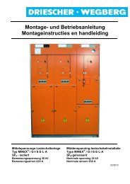
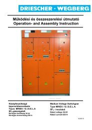
DRIESCHER WEGBERGNiederspannungsverteilungLV distribution boardBerührungssichereAbdeckleisteCover protected againstdangerous contact1 DRIESCHER WEGBERG DRIESCHER WEGBERGDer NS-Raum ist ausgerüstet:- <strong>mit</strong> einer NH-Sicherungslastschaltleiste nachDIN 43623 Gr. 3- für eine Bemessungsspannung von 500 V <strong>und</strong>einen Bemessungsstrom von 910 AThe LV-compartment is equipped:- with a LV fuse switch according to DIN 43623size 3- for a rated voltage of 500V and for a rated currentof 910ADie weitere optionale Ausrüstung des NS-Raumesbeinhaltet:- Abgangsleisten, ausgebildet als NH-Sicherungsleistenfür Strom 400/630 A max. 8 Stück <strong>und</strong>Reservefeldabdeckungen abhängig von der Anzahlder Abgangsleisten.- NH-Sicherungseinsätze nach DIN 43620 <strong>und</strong>DIN VDE 0636 Teil 22- 1 oder 3 Stromwandler umklemmbar, für Ströme1000/600/300A an der Eingangsseite desHauptschalters.- 1 oder 3 Anzeigeinstrumente: Ausführung <strong>mit</strong>Schleppzeiger 0-5/6A, 15 min.- Spannungsmesser <strong>mit</strong> Umschalter- Steckdose <strong>mit</strong> Sicherungen <strong>und</strong> Klemmleiste- Baustromeinführungen in der rechten <strong>und</strong> linkenSeitenwand des NS–Raumes je eine- Zählerschrank- Anschlussbereiche á 40mm Breite zum Anschlusseines Notstromaggregates <strong>mit</strong>telsKlemmklauenThe further optional equipment of the LV compartmentsconsists of:- Strips for outgoing feeder, made as LV-fusestrips for current 400/630A max. 8 pieces andcovers for reserve feeders depending on quantityof strips for outgoing feeders.- LV-fuse links according to DIN 43620 and DINVDE 0636 part 22- 1 or 3 reconnectable current transformers, forcurrents 1000/600/300A at the incoming supplyside of the main switch- 1 or 3 indicating instruments: model with slavepointer (0-5/6A, 15 min.)- Voltmeter with selector switch- Socket with fuses and terminal strip- Worksite electrical incoming supply in the rightand left side wall of the LV-compartment eachone piece- Meter cabinet- connecting areas á 40mm width for theconnection of an emergency generating set viaclamping claws.Die Anzeigeinstrumente, Steckdose, Sicherungen<strong>und</strong> Klemmleiste sind in einer Instrumententafeloberhalb der NS-Verteilung eingebaut.Die PEN -Schiene für die gesamte Erdung der Stationliegt im unteren Bereich des NS-Raumes. DieKabelhalterung befindet sich im F<strong>und</strong>ament.The indicating instruments, socket, fuses andterminal strip are installed in an instrument panelsituated above the LV distribution board.The PEN-rail for the complete earthing of the stationis situated in the lower area of the LV compartment.The cable support is located in the fo<strong>und</strong>ation.<strong>K1124</strong> / <strong>K1227</strong> 11
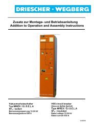
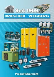
DRIESCHER WEGBERGTechnische DatenMaßbild, Gewichte <strong>und</strong> Abmessungen<strong>Kunststoff</strong>-F<strong>und</strong>amentwanneTechnical dataDimension drawing and weightsPolyester fo<strong>und</strong>ation trough DRIESCHER WEGBERG(1) Baustromdurchführung 100 beidseitig,<strong>mit</strong> Zugentlastung.(2) Max. Türöffnungswinkel 135°.(1) Worksite electrical incoming supply 100 onboth sides, with pull relief.(2) Max. door opening angle 135°.PlatzbedarfSpace requirementsStellfläche ca. 2,65 m² footprint approx. 2,65 m²Fläche bei geöffneten Türen ca. 5,05 m² space with opened doors approx. 5,05 m²GewichteWeightsLeergehäuse inkl.F<strong>und</strong>amentwanne GFPca. 340 kgempty housing incl. fo<strong>und</strong>ationtrough GFPapprox. 340 kgF<strong>und</strong>amentwanne GFP ca. 110 kg fo<strong>und</strong>ation trough GFP approx. 110 kgGesamtgewicht ohneTransformatorca. 830 kgtotal weight: withouttransformerapprox. 830 kg<strong>mit</strong> Transformator 630 kVA ca. 2800 kg with transformer 630 kVA approx. 2800 kgAbmessungenMax Trafoabmessungen:L x B x H = 1250 x 900 x 1700 mmDimensionsMaximum transformer dimensions:L x W x H = 1250 x 900 x 1700 mmÖlauffangwanne ca. 700 l Oil collector tank approx. 700 l12 <strong>K1124</strong> / <strong>K1227</strong>
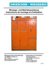
DRIESCHER WEGBERGBeton-F<strong>und</strong>amentwanneConcrete fo<strong>und</strong>ation trough DRIESCHER WEGBERG(3) Baustromdurchführung 100 beidseitig,<strong>mit</strong> Zugentlastung.(4) Max. Türöffnungswinkel 135°.(3) Worksite electrical incoming supply 100 onboth sides, with pull relief.(4) Max. door opening angle 135°.PlatzbedarfSpace requirementsStellfläche ca. 2,65 m² footprint approx. 2,65 m²Fläche bei geöffneten Türen ca. 5,05 m² space with opened doors approx. 5,05 m²GewichteWeightsLeergehäuse inkl.Beton-F<strong>und</strong>amentwanneca. 2630 kgempty housing incl. concretefo<strong>und</strong>ation troughapprox. 2630 kgF<strong>und</strong>amentwanne Beton ca. 2400 kg concrete fo<strong>und</strong>ation trough approx. 2400 kgGesamtgewicht ohneTransformatorca. 3120 kgtotal weight: withouttransformerapprox. 3120 kg<strong>mit</strong> Transformator 630 kVA ca. 5100 kg with transformer 630 kVA approx. 5100 kgAbmessungenMax Trafoabmessungen:L x B x H = 1250 x 900 x 1700 mmDimensionsMaximum transformer dimensions:L x W x H = 1250 x 900 x 1700 mm<strong>K1124</strong> / <strong>K1227</strong> 13
DRIESCHER WEGBERGTransport, Aufstellung <strong>und</strong> MontageAuf Vollständigkeit <strong>und</strong> Transportschäden prüfen: Vollständigkeit <strong>und</strong> Richtigkeit der Lieferung anhandder Lieferscheine <strong>und</strong> Beipacklisten prüfen. Kontrolle / Vergleich des Lieferscheins <strong>mit</strong> denBestellunterlagen. Zubehör auf Vollständigkeit überprüfen. Eventuelle Transportschäden sofort der FirmaDRIESCHER melden.Transport, erection and assemblyCheck for completeness and transport damages: Check completeness and correctness of the deliverybased on delivery note and packing list. Check / compare the delivery note and theordering documents Check completeness of accessories. Report any transport damage immediately to companyDRIESCHER.Abladen <strong>und</strong> Transport zum Aufstellungsort bzw.ZwischenlagerBei nicht ordnungsgemäßem Transportbesteht eine Gefahr für Personen <strong>und</strong> Anlagenteile.Stellen Sie sicher, dass die verwendetenHebezeuge <strong>und</strong> Transport<strong>mit</strong>tel den Anforderungenan Aufbau <strong>und</strong> Belastunggenügen. Achten Sie auf das Gesamtgewichtder Station bei der Verladung.Die Stationen können beim Transport beschädigtwerden.Seile <strong>und</strong> Ladegeschirr so einhängen, dasskeine großen Kräfte auf die Stationswändeausgeübt werden. (evtl. Holzzwischenlagebenutzen)Bänder <strong>und</strong> Seile je nach Schwerpunktlageso einstellen, dass die Station waagerechthängt!Vermeiden Sie ruckartige Bewegungen!Discharge and transport to the erection site resp.interim storageWith an improper transport, there is a risk forpersons and switchgear parts.Make sure, that all used lifting devices andmeans of transport fulfill the requirements ofassembly and load carrying capacity.For loading pay attention to the total stationweight.The substations can be damaged duringtransport.Hook in ropes and cargo gear in such a way,that no big forces will effect on the stationwalls (possibly use wood inter layer).Adjust ribbons and ropes according to thecentre of gravity, so that the substation hangsin horizontal position!Avoid sudden movements!14 <strong>K1124</strong> / <strong>K1227</strong>
DRIESCHER WEGBERGHebeplanKranen der Kompaktstation <strong>mit</strong> <strong>Kunststoff</strong>-F<strong>und</strong>ament <strong>mit</strong> eingebautem TransformatorDie Station kann komplett ausgestattet an der F<strong>und</strong>amentwanneangehoben werden. Verwenden Siedazu die an der F<strong>und</strong>amentwanne angebrachtenHebeschlaufen.Lifting planCraning of kiosk substation with polyester fo<strong>und</strong>ationtrough with installed transformerThe completely equipped station can be lifted at thefo<strong>und</strong>ation trough. For this use the lifting eyeboltslocated at the fo<strong>und</strong>ation trough.1 DRIESCHER WEGBERG DRIESCHER WEGBERG(1) Evtl. Holzzwischenlage (1) Possible wood interlayerKranen der Kompaktstation <strong>mit</strong> <strong>Kunststoff</strong>-F<strong>und</strong>ament ohne eingebautem TransformatorCraning of kiosk substation with polyester fo<strong>und</strong>ationtrough without installed transformer1 DRIESCHER WEGBERG DRIESCHER WEGBERG2Wird die Station ohne eingebauten Transformatorangehoben, müssen zwei ausreichend dimensionierte<strong>Kunststoff</strong>-Hebebänder über die vier Ecken desF<strong>und</strong>amentkragens angelegt werden.Die Hebebänder müssen dabei hinter denGewindestangen (2) liegen!If the station is lifted without transformer, two plasticliftingties with adequate dimensions have to befastened via the four edges of the fo<strong>und</strong>ation flange.The lifting ties must be behind the threadedrods (2)!<strong>K1124</strong> / <strong>K1227</strong> 15
DRIESCHER WEGBERGKranen der Station <strong>mit</strong> Beton-F<strong>und</strong>amentwanneDie Station kann komplett ausgestattet an der F<strong>und</strong>amentwanneangehoben werden. Verwenden Siedazu die an der F<strong>und</strong>amentwanne angebrachtenKranungsösen.Craning of the station with concrete fo<strong>und</strong>ationtroughThe completely equipped station can be lifted at thefo<strong>und</strong>ation trough. For this use the lifting eyeboltslocated at the fo<strong>und</strong>ation trough.1 DRIESCHER WEGBERG DRIESCHER WEGBERG DRIESCHER WEGBERG DRIESCHER WEGBERG(2) Evtl. Holzzwischenlage (2) Possible wood interlayerBodenaushubDie Baugrube muss einen tragfähigen Boden haben.Unebenheiten müssen durch eine waagerecht abgezogeneKies-, Split- oder Sandschicht ausgeglichenwerden. Bei schwierigen Bodenverhältnissen ist einUnterbau aus Magerbeton oder Schwellen empfehlenswert.(1) Ausgleichsschicht Kies, Split oder Sand 15 cmstark, Körnung 0-16 mm(2) Mittelspannungs-Kabel(3) Niederspannungs-KabelBasement excavationThe fo<strong>und</strong>ation pit must have a sustainable gro<strong>und</strong>.Unevenness has to be balanced with a horizontalgrit-, split- or sand layer. With difficult soil conditionsa supporting structure of lean concrete or thresholdsis recommendable.(1) Balance layer grit, split or sand 15cm strong,graining 0-16mm(2) MV-cable(3) LV-cable16 <strong>K1124</strong> / <strong>K1227</strong>
DRIESCHER WEGBERGBaugrubenvorschlag für Stationen <strong>mit</strong> <strong>Kunststoff</strong>-F<strong>und</strong>amentFür Gründungen DIN VDE 0210 beachten!Bodenpressung mindestens 250kN / m 2 .Kabelgräben müssen an Ort <strong>und</strong> Stelle nach denErfordernissen festgelegt werden.Fo<strong>und</strong>ation pit proposal for substations with polyesterfo<strong>und</strong>ationObserve DIN VDE 0210 for formation!Bottom pressing minimum 250kN / m².Cable ducts have to be defined at site according tothe relevant requirements.Errichten eines PotentialerdersBeim Errichten des Potentialerders ist dieaktuell gültige VDE 0101-2 zu berücksichtigen!Installation of a potential earth electrodeObserve the actual valid standard VDE0101-2 for installation of a potential earthelectrode!Der Potentialerder muss in einem Abstand von1m umlaufend um die Ortsnetzstation verlegtwerden.Längenmaße / Breitenmaße sind demnach um2m zu erhöhen.The potential earth electrode has to be installedro<strong>und</strong> the substation in a distance of 1m.Dimensions of length and width are to be increasedfor about 2m. DRIESCHER WEGBERG DRIESCHER WEGBERG<strong>K1124</strong> / <strong>K1227</strong> 17
DRIESCHER WEGBERGBaugrubenvorschlag für Stationen <strong>mit</strong> Beton-F<strong>und</strong>amentwanneFür Gründungen DIN VDE 0210 beachten!Bodenpressung mindestens 250kN / m 2 .Kabelgräben müssen an Ort <strong>und</strong> Stelle nach denErfordernissen festgelegt werdenFo<strong>und</strong>ation pit proposal for substations withconcrete fo<strong>und</strong>ation troughObserve DIN VDE 0210 for formation!Bottom pressing minimum 250kN / m².Cable ducts have to be defined at site according tothe relevant requirements. DRIESCHER WEGBERG DRIESCHER WEGBERG18 <strong>K1124</strong> / <strong>K1227</strong>
DRIESCHER WEGBERGKabelanschlussEntfernen Sie zum Anschließen der Kabel:MS–seitig1. Stirnblech (1) der F<strong>und</strong>amentwanne.Die Abdeckung der Kabelanschlussräume derMS–Schaltanlage gemäß der Montage- <strong>und</strong> Betriebsanleitung.NS–seitig1. Stirnblech (1) der F<strong>und</strong>amentwanne.Cable connectionTo connect the cables remove::At MV side1. End plate (1) of fo<strong>und</strong>ation trough.Cover of cable connection compartments of theMV–switchgear according to the Operating andAssembly Instructions.At LV side1. End plate (1) of fo<strong>und</strong>ation trough. DRIESCHER WEGBERG DRIESCHER WEGBERG1<strong>mit</strong> <strong>Kunststoff</strong>-F<strong>und</strong>amentwannewith polyester fo<strong>und</strong>ation troughSollten bei einer Station <strong>mit</strong> Beton-F<strong>und</strong>amentwanneKabeldurchführungen vorhanden sein, Montageanleitungdes entsprechenden Herstellers beachten!<strong>mit</strong> Beton-F<strong>und</strong>amentwannewith concrete fo<strong>und</strong>ation troughIf cable bushings are available at a station withconcrete fo<strong>und</strong>ation trough, the mounting instructionsof the corresponding manufacturer have to beobserved.ErdungStellen Sie die Erdverbindung zum Erdreich her,indem Sie das bauseits verlegte Erdungsband oderden Tiefenerder an die Erdungsanlage der Stationanschließen.EarthingMake an earth connection to the gro<strong>und</strong> byconnecting the factory installed gro<strong>und</strong> strap or onsite the gro<strong>und</strong> rod to the earthing system.InbetriebnahmeMontagearbeiten prüfenKontrollieren Sie, ob alle Montagearbeiten ordnungsgemäßdurchgeführt wurden.Setting to workCheck assembly worksCheck if all assembly works were made correctly.<strong>K1124</strong> / <strong>K1227</strong> 19
DRIESCHER WEGBERGAustausch von StationskomponentenDer Komponentenwechsel erfolgt über dasabnehmbare Dach.Gehen Sie wie folgt vor: Lösen Sie die 6 Befestigungsschrauben (1) (3Stück an jeder Kopfseite im oberen Türrahmen)<strong>und</strong> entfernen Sie das Dach.Change of station componentsThe change of components takes place via theremovable roof.Follow these steps: Loosen the 6 fixing screws (1) (3 pcs. at eachupper door frames) and remove the roof.1Austausch der Mittelspannungs-SchaltanlageAchten Sie beim Einbau oder Wechsel derSchaltanlage darauf, dass alle Anschlussleitungender MS-Schaltanlage spannungslos<strong>und</strong> geerdet sind (Einhalten der 5 Sicherheitsregeln)!SF 6 -Schaltanlagen Typ G.I.S.E.L.A/MINEXChange of medium voltage switchgearWith the installation or change of theswitchgear take care that all connectingwires of the MV switchgear are dead andearthed (comply with the 5 safety rules)!SF 6 -switchgear type G.I.S.E.L.A/MINEX Entfernen Sie alle Anschlusskabel <strong>und</strong> Erdverbindungen. Nachdem das Dach abgehoben wurde, hängenSie die Schaltanlage an eine Hebevorrichtung(Kran o.ä.). Lösen Sie rückseitig der Schaltanlage die Befestigungsschrauben,ziehen die Schaltanlage nachvorne <strong>und</strong> heben sie nach oben aus der Stationheraus. Entfernen Sie die Befestigungsschrauben ausder Rückwand der Schaltanlage <strong>und</strong> schraubendiese an die neue Schaltanlage. Bauen Sie die neue Schaltanlage in umgekehrterReihenfolge ein.Remove all connecting cables and earth connections.After lifting the roof, hook switchgear in a liftingdevice (crane or similar).Unscrew the fixing screws at the back of theswitchgear, pull the switchgear to the front and liftit out of the station via the top.Remove the fixing screws from rear wall supportat the switchgear and screw these to the newswitchgear.Install the new switchgear in reverse sequence.20 <strong>K1124</strong> / <strong>K1227</strong>
DRIESCHER WEGBERGEinbau oder Wechsel des TransformatorsAchten Sie beim Einbau oder Wechsel desTransformators darauf, dass die entsprechendenAbgänge der MS–Schaltanlage<strong>und</strong> NS-Verteilung spannungslos <strong>und</strong>geerdet sind! (Einhalten der 5Sicherheitsregeln)Der Transformator wird beim Wechsel vonoben aus der Station herausgehoben bzw.in die Station eingebracht.Die Transformatorhaltegurte sind nur im Falle einesAustauschs des Transformators zu lösen.Gehen Sie beim Einbau wie folgt vor:a) Einbau des Transformators vor Ort:1. Dach lösen <strong>und</strong> entfernen.2. Öffnen Sie die Lüftungssteckblende auf derlinken Stationsseite <strong>und</strong> nehmen Sie dieseab.3. Bringen Sie den Transformator vorsichtig ein<strong>und</strong> schließen ihn an.b) Wechseln eines werksseitig eingebautenTransformators:1. Dach lösen <strong>und</strong> entfernen.2. Öffnen Sie die Lüftungssteckblende auf derlinken Stationsseite <strong>und</strong> nehmen Sie dieseab.3. Lösen Sie den Haltegurt des Transformators.4. Heben Sie den Transformator vorsichtig heraus<strong>und</strong> entfernen Sie von den Transformatorfüßendie Transformator-Haltebleche.5. Entfernen Sie die Transformatorhaltegurte.6. Befestigen Sie die Transformator-Haltebleche am neuen Transformator <strong>und</strong>heben Sie ihn vorsichtig in die Station.Abstände nach VDE 0101 beachten!7. Setzen Sie die Lüftungssteckblende ein <strong>und</strong>verschließen Sie diese.8. Legen Sie das Dach auf <strong>und</strong> verschraubenes.Installation or change of the transformerFor the installation or change of atransformer, take care that the relevantoutgoing supplies of the MV-switchgear andLV distribution board are dead and earthed!(Comply with the 5 safety rules)The transformer is lifted resp. put into thestation via the top.Only loosen the transformer holding belts in case thetransformer shall be changed.For the installation follow the following steps:a) Installation of transformer at site:1. Unfasten the roof and remove it.2. Open the detachable ventilation cover on theleft station side and remove it.3. Install the transformer carefully and connectsame.b) Change of factory installed transformer1. Unfasten the roof and remove it.2. Open the detachable ventilation coveron the left station side and remove it.3. Loosen the holding belt of the transformer.4. Lift the transformer carefully and remove thetransformer fixing sheets at the transformerfeet.5. Remove the transformer holding belts.6. Fix the transformer fixing sheets at the newtransformer and lift it carefully into the station.Observe the clearances according toVDE0101!7. Install the detachable ventilation cover andlock same.8. Attach the roof and screw it.<strong>K1124</strong> / <strong>K1227</strong> 21
DRIESCHER WEGBERGAustausch der Niederspannungs-SchaltanlageAchten Sie beim Einbau oder Wechsel derSchaltanlage darauf, dass alle Anschlussleitungender Schaltanlage <strong>und</strong> auch dieMittelspannungsseite des Transformatorsspannungslos <strong>und</strong> geerdet sind.(Einhalten der 5 Sicherheitsregeln)!Change of Low voltage switchgearDuring installation or change of theswitchgear, take care that all wiring cablesof the switchgear and also the MV side ofthe transformer are dead and earthed.(Comply to the 5 safety rules)!Entfernen Sie alle Anschlusskabel <strong>und</strong> Erdverbindungen.Nachdem das Dach abgehoben wurde, hängenSie die Schaltanlage an eine Hebevorrichtung(Kran o.ä.).Entfernen Sie jeweils die linke <strong>und</strong> rechte NH-Sicherungsleiste oder Sammelschienenabdeckung.Lösen Sie von vorne an der Schaltanlage jeweilslinks <strong>und</strong> rechts die Befestigungsschrauben, ziehenSie die Schaltanlage nach vorne <strong>und</strong> hebendiese nach oben aus der Station heraus.Bauen Sie die neue Schaltanlage in umgekehrterReihenfolge ein.Remove all connecting cables and earthconnections.After lifting the roof, put switchgear into a liftingdevice (crane or similar).Remove the left and right LV-fuse strip or busbarcover.Loosen the fixing screws on the left and rightside at the switchgear front, pull the switchgearto the front and lift it out of the station via the top.Install the new switchgear in reverse order.InstandhaltungWartung, Inspektion, InstandsetzungDRIESCHER-Kompaktstationen sind witterungsbeständig<strong>und</strong> wartungsarm. Es sollte jedoch regelmäßigeine Sichtkontrolle durchgeführt werden, um evtl.Schäden an oder in der Station feststellen zukönnen.Zur Wartung der Mittelspannungsschaltanlage<strong>und</strong> der Niederspannungsverteilungbeachten Sie bitte die entsprechendenBedienungsanleitungen.Vor Inbetriebnahme sind einige Probeschaltungendurchzuführen.Werden verschlissene oder beschädigte Schaltgerätekomponentenbzw. Stationsteile vorgef<strong>und</strong>en wendenSie sich bitte an unseren K<strong>und</strong>endienst, welcherIhnen gerne weiterhilft. Hier erhalten Sie auch Informationenzu original Ersatzteilen <strong>und</strong> Austauschkomponenten.Der Betreiber sollte darauf achten, dass die Stationsräumeimmer sauber <strong>und</strong> trocken sind.ServicingMaintenance, inspection, repairDRIESCHER kiosk substations are weather-resistantand require little maintenance only. However, visualinspection should be carried out on regular base fornoticing possible damages at or in the station.For maintenance purpose of MV and LVswitchgear please see the relevant manuals.Carry out some test operations beforecommissioning.In case of wear or damaged switch components orstation parts resp. so please contact our customerservice. Here you will achieve support and informationregarding original spare parts and replacementcomponents.Care should be taken by the user that the stationrooms are clean and dry.22 <strong>K1124</strong> / <strong>K1227</strong>
DRIESCHER WEGBERGEntsorgungDie Materialien der Station sollten möglichst recyceltwerden. Die Entsorgung der Station ist auf derGr<strong>und</strong>lage der bestehenden Rechtsvorschriften umweltschonendmöglich.Die Bestandteile der Station sind als Mischschrottoder durch weitestgehende Demontage umweltgerechtverwertbar als Sortenschrott <strong>und</strong> Mischschrott-Restanteil.Eine Rückgabe der Station an Firma <strong>Driescher</strong> ist zuden zum Zeitpunkt der Rückgabe geltenden Entsorgungskostenmöglich.In den Stationen sind hauptsächlich die folgendenMaterialien enthalten:Gehäuse Verzinkter Stahl Aluminium Glasfaserverstärkter <strong>Kunststoff</strong> BetonMittelspannungsschaltanlage Beachten Sie hierzu die Bedienungsanleitungder entsprechenden Mittelspannungsschaltanlage!Niederspannungsschaltanlage Verzinkter Stahl (Gr<strong>und</strong>gerüst) Kupfer (Sammelschiene ggf. versilbert) Gießharz auf Epoxidharzbasis (Stützer) <strong>Kunststoff</strong>e (Schaltleisten)Transformator Öl bzw. Gießharz MetallWaste disposalThe materials of the substation should be recycled asmuch as possible. Based on the actual legal regulations,the substation disposal can be realized ecofriendly.The substation components can be put to mixedscrap or sort scrap by disassembly to the greatestpossible extent and to mixed scrap-remaining parts inan environment-friendly and correct way.The substation can be returned to <strong>Driescher</strong> companyand for that expenses will be charged at actual,i.e. valid for disposal at date of such a return.The substations mainly consist of the following materials:Housing galvanized steel aluminium glass-fibre- reinforced polyester concreteMedium Voltage Switchgear Here, pls consider the Manual of the relevant MVswitchgearLow Voltage Switchgear galvanized steel (base frame) copper (bus bar, if applicable silver-plated) cast resin on epoxy resin base (insulators) plastics material (switching strips)Transformer oil or cast resin metalDie Entsorgung des Transformators istumweltgerecht entsprechend den gesetzlichenAnforderungen durchzuführen!The waste disposal of the transformer hasto be performed according to the environmentallegal standards.<strong>K1124</strong> / <strong>K1227</strong> 23
DRIESCHER WEGBERGAnhang ABetonf<strong>und</strong>ament AbdichtungBei einem komplett geschlossenen Betonf<strong>und</strong>amentist das beigestellte Dichtungsmaterial bei der Aufstellungan den unten angegebenen Positionen zu verwenden.Appendix ASealing of concrete fo<strong>und</strong>ationDuring the installation of a completely closed concretefo<strong>und</strong>ation the provided sealing material shouldbe used at the spots shown below. DRIESCHER WEGBERGMittelspannungMedium VoltageNiederspannungLow VoltageDichtungsmaterial zwischen F<strong>und</strong>ament <strong>und</strong>Verschlussplatte; oberflächenwasserdichtSealing material between fo<strong>und</strong>ation and blanking platewatertight against surface waterDichtungsmaterial zwischen F<strong>und</strong>ament<strong>und</strong> Station OberflächenwasserdichtSealing material between fo<strong>und</strong>ation andsubstation; watertight against surface waterKabeldurchführungen Fabr. Hauff; druckwasserdichtCable glands make Hauff; pressure-water-tight24 <strong>K1124</strong> / <strong>K1227</strong>