8763-1 Bedienungsanleitung Nt-Sdslt X.21 ... - Elcon Systemtechnik
8763-1 Bedienungsanleitung Nt-Sdslt X.21 ... - Elcon Systemtechnik
8763-1 Bedienungsanleitung Nt-Sdslt X.21 ... - Elcon Systemtechnik

Sie wollen auch ein ePaper? Erhöhen Sie die Reichweite Ihrer Titel.
YUMPU macht aus Druck-PDFs automatisch weboptimierte ePaper, die Google liebt.
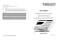
xpand<br />
NT-SDSLt <strong>X.21</strong><br />
<strong>X.21</strong><br />
SYNC<br />
Mains<br />
NT-SDSLt <strong>X.21</strong><br />
Montage- und Installationsanweisung<br />
Mounting and Installation Manual<br />
© ELCON <strong>Systemtechnik</strong> GmbH 2007 Art.-Nr. <strong>8763</strong>-1
Warn- und Sicherheitshinweise<br />
NT-SDSLt <strong>X.21</strong><br />
ACHTUNG Gefährliche elektrische Spannung<br />
Das Gerät ist erst frei von gefährlichen elektrischen Spannungen, wenn<br />
der Netzstecker und der SDSL-Anschluss vom Gerät getrennt sind.<br />
Bei Arbeiten am Gerät immer zuerst den Netzstecker aus der Wandsteckdose<br />
ziehen und das SDSL-Kabel am Gerät lösen.<br />
• Bitte lesen Sie die Warnhinweise, Sicherheitsbestimmungen sowie die Montage- und Installationsanweisung<br />
gewissenhaft durch, bevor Sie mit der Montage und Installation beginnen. Nur so können Sie<br />
das Gerät in seinem vollen Funktionsumfang nutzen und Schäden durch unsachgemäßen Gebrauch<br />
vermeiden (Feuer, Elektroschocks, Verletzungen usw.). Bewahren Sie die Montage- und Installationsanweisung<br />
sorgfältig auf.<br />
• Der NT-SDSLt <strong>X.21</strong> entspricht dem aktuellen Stand der Technik und den anerkannten sicherheitstechnischen<br />
Regeln.<br />
• Verwenden Sie beim Auspacken des Gerätes keine spitzen Gegenstände, um Beschädigungen an Gehäuse<br />
oder Kabeln zu vermeiden.<br />
• Betreiben Sie das Gerät und die mitgelieferten Teile (Kabel usw.) nur in einwandfreiem Zustand und<br />
unter strenger Beachtung der Montage- und Installationsanweisung.<br />
• Arbeiten am NT-SDSLt <strong>X.21</strong> einschließlich Öffnen des Gerätes darf nur autorisiertes Fachpersonal<br />
durchführen. Dabei sind die ESD-Schutzmaßnahmen nach DIN 100 015 zu beachten. Außer den in diesem<br />
Handbuch beschriebenen Handlungen dürfen keine Änderungen am Gerät sowie an den mitgelieferten<br />
Teilen (Kabel usw.) vorgenommen werden.<br />
• Achtung: Gefährliche elektrische Spannungen! Vor Öffnen des Gerätes unbedingt Netzstecker ziehen<br />
und Anschlusskabel von den Schnittstellen entfernen! Berühren Sie keine unisolierten Drähte oder<br />
Klemmen, wenn die Signalleitungen noch angeschlossen sind.<br />
• Vermeiden Sie Arbeiten am Gerät und dessen Komponenten bei Gewittertätigkeit (Trennen und Herstellen<br />
von Kabelverbindungen). Es kann zu gefährlichen elektrischen Spannungen durch Blitzeinschläge<br />
kommen.<br />
• Beachten Sie die Leistungsangaben auf dem Typschild des NT-SDSLt <strong>X.21</strong>. Das Typschild befindet<br />
sich auf der Geräterückseite. Das Gerät darf nicht weiter als 1,5 Meter von der Steckdose entfernt montiert<br />
werden.<br />
• Das Gerät besitzt keine eigene Trennvorrichtung zur Unterbrechung der Spannungsversorgung, da es<br />
für Dauerbetrieb ausgelegt ist. Achten Sie daher darauf, dass der Netzstecker stets leicht zugänglich ist.<br />
Zum Trennen des Gerätes von der Netzspannung immer zuerst den Netzstecker aus der Netzsteckdose<br />
ziehen.<br />
• Verlegen Sie Netz- und Anschlusskabel so, dass eine Unfallgefahr durch Stolpern oder Hängen bleiben<br />
ausgeschlossen wird.<br />
• Betreiben Sie das Gerät nur im Temperaturbereich zwischen -5°C und +45°C!<br />
• Schützen Sie das NT-SDSLt <strong>X.21</strong> vor direkter Sonneneinstrahlung und vor Feuchtigkeit. Verwenden<br />
Sie dieses Gerät nicht in der Nähe von Wasser, z.B. in der Nähe eines Waschraumes oder einer Küchenspüle,<br />
in feuchter Umgebung oder in der Nähe eines Swimmingpools.<br />
• Wenn Sie das Gerät aus einer kalten Umgebung in eine wärmere Umgebung bringen, dann kann dies zu<br />
einer Betauung des Gerätes führen. Betaute Geräte dürfen nicht in Betrieb genommen werden. Warten<br />
Sie mit der Inbetriebnahme, bis das Gerät trocken ist.<br />
• An den Schnittstellen des NT-SDSLt <strong>X.21</strong> dürfen nur Geräte angeschlossen werden, die die elektrischen<br />
Sicherheitsbestimmungen nach EN 60950 erfüllen und das CE-Zeichen tragen.<br />
• Alle angeschlossenen Geräte müssen passende Steckverbindungen besitzen, anderenfalls sind geeignete<br />
Adapter zu verwenden.<br />
• Alle angeschlossenen Geräte dürfen nur an den vorgesehenen Schnittstellen betrieben werden.<br />
• Beachten Sie die Installations- und Sicherheitshinweise und halten Sie diese ein.<br />
Version: 2007/12/18
NT-SDSLt <strong>X.21</strong><br />
Warnings and Safety Instructions<br />
WARNING Dangerous electrical voltage<br />
The device is only free of dangerous electrical voltages when the mains<br />
plug and the SDSL connection are removed from the unit.<br />
For all works on the device, first pull the mains connector out of the wall<br />
socket and remove the SDSL cable from the unit.<br />
• Please read the warnings, safety instructions and the mounting and installation manual carefully before<br />
you start assembling or installing the device. These instructions enable you to use the full functionality<br />
of the device and to avoid damage which may result from improper use (fire, electric shock, injuries<br />
etc.). Keep this manual at a safe place.<br />
• The NT-SDSLt <strong>X.21</strong> has been manufactured according to state-of-the-art technology and complies with<br />
the generally accepted safety standards.<br />
• Do not use sharp-edged tools for unpacking the device: they could damage cables or the enclosure.<br />
• The device and its accessories (cable etc.) shall be operated only in faultless condition, while strictly<br />
observing these mounting and installation manual.<br />
• Only authorized personnel are allowed to open the device and to carry out interventions in the<br />
NT-SDSLt <strong>X.21</strong>. Please observe the protective measures with respect to electrostatic discharge as per<br />
DIN 100 015. Manipulations on the device or attached parts (cables etc.) other than those described in<br />
this manual are not allowed.<br />
• Warning: Dangerous electric voltage! Before opening the device, remove the mains plug and disconnect<br />
the cables from the interfaces! Do not touch any bare wires or terminals when the signal lines are<br />
still connected.<br />
• Refrain from interventions in the device and its parts during thunderstorms (in particular, avoid plugging<br />
and unplugging of cables). Dangerous electrical voltages may occur as a result of lightning strokes.<br />
• Make sure you read the specifications on the NT-SDSLt <strong>X.21</strong> nameplate. The name-plate is located on the<br />
back panel of the device. The device shall not be installed farther than 1.5 m from the socket.<br />
• The device has no separate switch for interrupting the power supply, since it has been designed for continuous<br />
operation. So make sure the mains plug is always easily accessible. To disconnect the unit from<br />
the power supply, always pull the power plug out of the power socket first.<br />
• Lay the power supply and connection cables in a way to prevent accidents (such as tripping over the cables).<br />
• The device shall be operated only between -5°C and +45°C.<br />
• Protect the NT-SDSLt <strong>X.21</strong> from direct sun radiation and extreme humidity. ·Do not install or operate<br />
this device near water, e.g. next to a wash-room, kitchen sink, in humid surroundings or next to a<br />
swimming pool.<br />
• When the device is taken from a cold environment into a warmer one, it may be bedewed. In this case<br />
the equipment must not be put into operation. So please wait until the device is dry again.<br />
• Connect to the NT-SDSLt <strong>X.21</strong> interfaces only such terminal devices which meet the safety requirements<br />
acc. to EN 60950 and which are labelled with the CE symbol.<br />
• The terminal devices shall have appropriate connectors; otherwise adequate adapters have to be used.<br />
• Connected equipment shall only be operated at the corresponding interfaces that have been designed for<br />
them.<br />
• Pay attention to the instructions on installation and safety and comply with them.<br />
Version: 2007/12/18<br />
1
Sehr geehrte Kundin, sehr geehrter Kunde,<br />
2<br />
NT-SDSLt <strong>X.21</strong><br />
mit dem ELCONnect xpand NT-SDSLt <strong>X.21</strong> haben Sie ein Gerät erhalten, welches nach dem<br />
neuesten Stand der Technik entwickelt und unter höchsten Anforderungen gefertigt wurde.<br />
Sollte einmal etwas nicht wie beschrieben funktionieren, nehmen Sie bitte mit Ihrem Service-<br />
Provider Kontakt auf, von dem Sie dieses Gerät erworben haben. Dieser verfügt über die notwendigen<br />
Fachkenntnisse und wird Ihnen gern weiterhelfen.<br />
Wir wünschen Ihnen viel Freude mit Ihrem NT-SDSLt <strong>X.21</strong>.<br />
Dear Customer,<br />
Your ELCONnect xpand NT-SDSLt <strong>X.21</strong> is a product that represents state-of-the-art technology<br />
and has been manufactured in compliance with highest quality standards.<br />
Should it happen that something is acting up other than described, please contact your service<br />
provider who has offered you the device. He will have the necessary knowledge to provide<br />
you with the required support.<br />
And now enjoy your NT-SDSLt <strong>X.21</strong>!<br />
Version: 2007/12/18
NT-SDSLt <strong>X.21</strong><br />
Inhalt / Contents<br />
DEUTSCH.................................................................................................................... 4<br />
1 Allgemeines ....................................................................................................................... 4<br />
1.1 Beschreibung des NT-SDSLt <strong>X.21</strong> ............................................................................ 4<br />
1.2 Lieferumfang.............................................................................................................. 4<br />
2 Montage............................................................................................................................. 5<br />
2.1 Vor der Montage ........................................................................................................ 5<br />
2.2 Montieren des Gerätes an einer Wand ....................................................................... 6<br />
2.3 Verkabelung ............................................................................................................... 7<br />
3 Betrieb ............................................................................................................................... 8<br />
3.1 Inbetriebnahme........................................................................................................... 8<br />
3.2 Anzeige der Leuchtdioden ......................................................................................... 9<br />
3.3 Pflege und Wartung.................................................................................................... 9<br />
3.4 Außerbetriebnahme .................................................................................................... 9<br />
4 Technische Daten............................................................................................................ 10<br />
5 Belegung der Steckverbinder ........................................................................................ 11<br />
6 Wichtige Hinweise.......................................................................................................... 11<br />
6.1 Herstellererklärung................................................................................................... 11<br />
6.2 Gewährleistung......................................................................................................... 12<br />
6.3 Rechte und Warenzeichen........................................................................................ 12<br />
ENGLISH................................................................................................................... 13<br />
1 Introduction .................................................................................................................... 13<br />
1.1 Description of the NT-SDSLt <strong>X.21</strong>.......................................................................... 13<br />
1.2 Scope of delivery...................................................................................................... 13<br />
2 Mounting......................................................................................................................... 14<br />
2.1 Before mounting....................................................................................................... 14<br />
2.2 Mounting the device to a wall.................................................................................. 15<br />
2.3 Cabling ..................................................................................................................... 16<br />
3 Operation ........................................................................................................................ 17<br />
3.1 Start-up..................................................................................................................... 17<br />
3.2 LED display.............................................................................................................. 18<br />
3.3 Maintenance ............................................................................................................. 18<br />
3.4 Shut-down ................................................................................................................ 18<br />
4 Technical data................................................................................................................. 19<br />
5 Pin assignment of connectors ........................................................................................ 20<br />
6 Important notes .............................................................................................................. 20<br />
6.1 Manufacturer´s declaration ...................................................................................... 20<br />
6.2 Warranty................................................................................................................... 21<br />
6.3 Rights and trademarks.............................................................................................. 21<br />
Version: 2007/12/18<br />
3
DEUTSCH<br />
1 Allgemeines<br />
1.1 Beschreibung des NT-SDSLt <strong>X.21</strong><br />
NT-SDSLt <strong>X.21</strong><br />
Der NT-SDSLt <strong>X.21</strong> bildet den Abschluss für das SDSL-Signal an der Teilnehmerseite und<br />
stellt die Schnittstelle zum Teilnehmer bereit. Als Schnittstelle zum Teilnehmer ist eine Datenschnittstelle<br />
nach ITU-T V.11 vorhanden. Die Netzspannung (110 V � bis 240 V �) wird<br />
dem NT-SDSLt <strong>X.21</strong> über das Netzanschlusskabel zugeführt.<br />
Der NT-SDSLt <strong>X.21</strong> ist in einem Kunststoffgehäuse untergebracht und für Wandmontage<br />
vorgesehen.<br />
1.2 Lieferumfang<br />
Zum Lieferumfang gehören:<br />
• Verpackung<br />
• Gerät NT-SDSLt <strong>X.21</strong><br />
• Netzanschlusskabel<br />
• SDSL-Kabel (einseitig RJ45)<br />
• Montageanleitung und Bohrschablone<br />
• Beipack<br />
Im Beipack des Gerätes finden Sie folgendes Installationsmaterial:<br />
Benennung Menge Bemerkung<br />
Holzschraube 2 DIN96-3,5×30-A2-70<br />
Dübel 2 Länge 30 mm<br />
Plombe 1 6L.3291.005.00-A003<br />
• Optional ist auch das V.11-Anschlusskabel erhältlich.<br />
4 Version: 2007/12/18
NT-SDSLt <strong>X.21</strong><br />
2 Montage<br />
2.1 Vor der Montage<br />
Das Gerät NT-SDSLt <strong>X.21</strong> ist für eine Wandmontage vorgesehen. Beachten Sie vor der Montage<br />
folgende Hinweise:<br />
• Überprüfen Sie, ob alle benötigten Teile vorhanden und unbeschädigt sind. Ein defektes<br />
Gerät darf nicht montiert werden.<br />
• Der Montageort darf nicht direkter Wärme- oder Sonneneinstrahlung ausgesetzt sein.<br />
Beachten Sie die Anforderungen an die Umgebungstemperatur. Die Angaben hierzu<br />
finden Sie bei den technischen Daten.<br />
• Der Montageort muss trocken sein. Montieren Sie das Gerät nicht an Orten, an denen<br />
Wasserdämpfe oder aggressive Dämpfe auftreten.<br />
• Montieren Sie das Gerät in der Nähe eines Stromanschlusses. Die Netzsteckdose muss<br />
den Richtlinien der VDE sowie den Bestimmungen der örtlichen Versorgungsunternehmen<br />
entsprechen. Beachten Sie die Länge der anzuschließenden Kabel.<br />
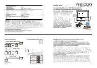
• Berücksichtigen Sie bei der Wahl des Montageortes den erforderlichen Freiraum um<br />
das Gehäuse für die Montage und Verkabelung (siehe untenstehendes Bild). Das Gehäuse<br />
(Abmessungen: 173 mm × 150 mm) muss mit der gesamten Gehäusefläche an<br />
der Wand (ebene Fläche) anliegen und darf nicht über Wandkanten hinausragen.<br />
• Beachten Sie die vorn aufgeführten Warn- und Sicherheitshinweise.<br />
Version: 2007/12/18<br />
Platzbedarf<br />
NT-SDSLt <strong>X.21</strong><br />
Kabelanschluss-<br />
60 mm<br />
bereich<br />
10 mm<br />
Geräteunterkante<br />
5
2.2 Montieren des Gerätes an einer Wand<br />
NT-SDSLt <strong>X.21</strong><br />
Das Gerät wird mit 2 Schrauben an einer ebenen Wand befestigt, der Kabelanschlussbereich<br />
zeigt nach unten. Gehen Sie bei der Montage in folgender Reihenfolge vor:<br />
1. Markieren Sie die beiden Bohrlöcher mit Hilfe der Bohrschablone. Achten Sie darauf,<br />
dass die Bohrlöcher senkrecht übereinander angeordnet sind.<br />
ACHTUNG: Achten Sie darauf, dass sich im Bereich der Bohrlöcher keine Versorgungsleitungen<br />
(Gas, Wasser, Strom usw.) befinden.<br />
2. Bohren Sie zwei Bohrlöcher mit einem Durchmesser von 6 mm und einer minimalen<br />
Tiefe von 40 mm.<br />
3. Setzen Sie die Dübel in die Bohrlöcher ein.<br />
4. Schrauben Sie die beiden Holzschrauben so weit in die Dübel ein, dass zwischen dem<br />
Schraubenkopf und der Wand ein Abstand zwischen 1,5 mm und 2 mm besteht. Prüfen<br />
Sie den festen Sitz der Schrauben.<br />
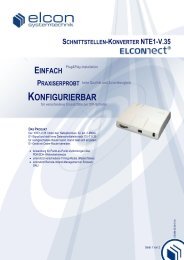
5. Setzen Sie das Gerät mit den Schraubenaufnahmen (Geräterückseite) an den Schraubenköpfen<br />
an und drücken Sie es nach unten bis zum Anschlag. Prüfen Sie den festen<br />
Sitz des Gerätes. Die Holzschrauben sollen soweit eingeschraubt sein, dass das Gerät<br />
fest an der Wand sitzt.<br />
6. Verschließen Sie die Gehäuseklappe mit der im Beipack befindlichen Plombe.<br />
Geräterückseite<br />
Schraubenaufnahmen<br />
6 Version: 2007/12/18
NT-SDSLt <strong>X.21</strong><br />
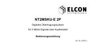
2.3 Verkabelung<br />
Der Anschluss des SDSL-Kabels und des Teilnehmerkabels erfolgt an den externen Steckverbindern<br />
des NT-SDSLt <strong>X.21</strong>.<br />
Endgerät<br />
V.11<br />
2.3.1 Benötigte Anschlusskabel<br />
Netzkabel<br />
SDSL-Kabel<br />
Service<br />
Provider<br />
V.11-Schnittstelle<br />
Mit dem V.11-Kabel wird die Verbindung zwischen dem NT-SDSLt <strong>X.21</strong> und Ihrem Endgerät<br />
hergestellt. Dieses Kabel ist nicht im Lieferumfang des NT-SDSLt <strong>X.21</strong> enthalten.<br />
SDSL-Schnittstelle<br />
Mit dem SDSL-Kabel wird die Verbindung zwischen dem NT-SDSLt <strong>X.21</strong> und Ihrem Service-Provider<br />
hergestellt. Dieses Kabel ist im Lieferumfang des NT-SDSLt <strong>X.21</strong> enthalten.<br />
Spannungsversorgung<br />
Mit dem Netzanschlusskabel wird der NT-SDSLt <strong>X.21</strong> mit einer Netzspannung im Bereich<br />
von 110 V � ... 240 V � versorgt. Dieses Kabel ist im Lieferumfang des NT-SDSLt <strong>X.21</strong><br />
enthalten.<br />
2.3.2 Anschließen der Kabel<br />
HINWEIS: Halten Sie das Gerät beim Stecken der Kabel fest.<br />
Gehen Sie bei der Verkabelung in folgender Reihenfolge vor:<br />
1. Schließen Sie das V.11-Kabel am <strong>X.21</strong>-Steckverbinder des NT-SDSLt <strong>X.21</strong> an. Das<br />
andere Ende des Kabels wird am Endgerät an der entsprechenden Schnittstelle angeschlossen.<br />
2. Schließen Sie das SDSL-Kabel mit dem einen Ende an dem SDSL-Steckverbinder des<br />
NT-SDSLt <strong>X.21</strong> an. Das anderen Ende wird am Netzübergabepunkt Ihres Service-<br />
Providers angeschlossen. Befolgen Sie hierzu die Hinweise und Installationsanweisungen<br />
Ihres Serviceproviders.<br />
3. Verbinden Sie nun das Netzanschlusskabel mit dem Netz-Steckverbinder des<br />
NT-SDSLt <strong>X.21</strong> und stecken Sie anschließend das andere Ende in die Netzsteckdose.<br />
HINWEIS: Durch Zuführen der Netzspannung wird das Gerät eingeschaltet. Weitere Hinweise<br />
zur Inbetriebnahme finden Sie im folgenden Kapitel.<br />
Version: 2007/12/18<br />
7
3 Betrieb<br />
Vor der Inbetriebnahme beachten Sie bitte folgende Hinweise:<br />
NT-SDSLt <strong>X.21</strong><br />
• Damit eine Verbindung zustande kommt, muss Ihr Service-Provider die SDSL-<br />
Verbindung in der Zentrale freigeschaltet haben. Stellen Sie vor der Verkabelung sicher,<br />
dass der Bereitstellungstag für den Anschluss erreicht ist.<br />
• Je nach Art des Ihnen zur Verfügung gestellten Dienstes können Systemeinstellungen<br />
an Ihrem Endgerät notwendig sein. Die Angaben hierzu erfahren Sie von Ihrem Service-Provider.<br />
• Das Laden neuer Gerätesoftware wird - wenn nötig - durch Ihren Service-Provider<br />
über die SDSL-Verbindung erledigt. Dies kann nur erfolgen, wenn Ihr Gerät in Betrieb<br />
ist und Sie die Netzspannung dauerhaft nicht unterbrechen.<br />
3.1 Inbetriebnahme<br />
Das Einschalten des Gerätes erfolgt durch Zuführung der Netzspannung. Die Leuchtdioden<br />
zeigen den momentanen Zustand des Gerätes an:<br />
1. Nach dem Einschalten muss die grüne LED „Mains“ dauerhaft leuchten.<br />
2. Empfängt der NT-SDSLt <strong>X.21</strong> ein Signal über die SDSL-Verbindung, beginnt die<br />
gelbe LED „SYNC“ zu blinken.<br />
3. Nach erfolgreichem Verbindungsaufbau zu Ihrem Service-Provider leuchtet die gelbe<br />
LED „SYNC“ dauerhaft.<br />
4. Die Verbindung zu Ihrem Endgerät ist in Ordnung, wenn die gelbe LED „<strong>X.21</strong>“ dauerhaft<br />
leuchtet.<br />
5. Der NT-SDSLt <strong>X.21</strong> ist jetzt betriebsbereit, ein Datenaustausch ist möglich.<br />
HINWEIS: Falls Sie Ihr Gerät nicht in Betrieb nehmen können, überprüfen Sie die ordnungsgemäße<br />
Verkabelung. Wenn Sie die Probleme nicht beheben können, wenden Sie sich bitte an<br />
Ihren Service-Provider.<br />
<strong>X.21</strong><br />
SYNC<br />
Mains<br />
NT-SDSLt <strong>X.21</strong><br />
8 Version: 2007/12/18
NT-SDSLt <strong>X.21</strong><br />
3.2 Anzeige der Leuchtdioden<br />
LED SDSL<br />
gelbe LED „SYNC“<br />
AUS<br />
kein Empfangssignal oder<br />
Verbindungsfehler (Loss<br />
of Signal, ...) erkannt<br />
AN<br />
(Normalzustand)<br />
BLINKT<br />
langsam<br />
BLINKT<br />
schnell<br />
3.3 Pflege und Wartung<br />
SDSL-Verbindung ist in<br />
Ordnung;<br />
in strukturierten Modi:<br />
Rahmensynchronität<br />
SDSL-Aktivierungsphase<br />
(in strukturierten Modi bis<br />
zur Rahmensynchronität;<br />
im unstrukturierten Modus<br />
bis Signal ungleich AIS)<br />
Interne Schleife geschlossen<br />
V.11<br />
gelbe LED „<strong>X.21</strong>“<br />
keine Datenübertragung<br />
zum Endgerät (Signal<br />
„Dauer-1“ erkannt<br />
(konfigurierbar))<br />
Datenübertragung zum<br />
Endgerät (Signal ungleich<br />
„Dauer-1“ erkannt<br />
(konfigurierbar))<br />
Externe Schleife geschlossen<br />
Netzspannung<br />
grüne LED „Mains“<br />
keine Netzspannung oder<br />
Selbsttest fehlerhaft<br />
Netzspannung vorhanden,<br />
Selbsttest ist in Ordnung<br />
Ihr NT-SDSLt <strong>X.21</strong> ist wartungsfrei. Die Reinigung erfolgt mit einem trockenen Tuch. Verwenden<br />
Sie niemals scheuernde oder ätzende Reinigungsmittel.<br />
HINWEIS: Ziehen Sie den Netzstecker aus der Steckdose bzw. nehmen Sie das Gerät während<br />
der Reinigung außer Betrieb.<br />
3.4 Außerbetriebnahme<br />
Sollten Sie aus besonderem Anlass das Gerät außerbetriebnehmen müssen, gehen Sie beim<br />
Entfernen der Kabel folgendermaßen vor:<br />
HINWEIS: Halten Sie das Gerät beim Lösen der Geräteverkabelung fest.<br />
1. Ziehen Sie zuerst den Netzstecker aus der Netzsteckdose.<br />
2. Lösen Sie nun den Steckverbinder des SDSL-Kabels vom Netzübergabepunkt Ihres<br />
Service-Providers.<br />
3. Entfernen Sie nun alle Kabel vom Gerät.<br />
Jetzt kann das Gerät von der Wand abgenommen werden.<br />
Version: 2007/12/18 9
4 Technische Daten<br />
10<br />
NT-SDSLt <strong>X.21</strong><br />
Gehäuse<br />
Abmessungen 173 mm × 150 mm × 45 mm (B × T × H)<br />
Gewicht ca. 400 g<br />
Gehäusematerial Thermoplastischer Kunststoff, Brennbarkeitsklasse UL94-V0<br />
Spannungsversorgung<br />
Netzspannungsbereich 110 V � … 240 V �<br />
Frequenzbereich 50 Hz … 60 Hz<br />
Leistungsaufnahme < 8 W<br />
Anschlusskabel (im Lieferumfang)<br />
Länge des SDSL-Anschlusskabels ca. 1 m<br />
Länge des Netzanschlusskabels ca. 2 m<br />
Betriebsbedingungen<br />
Temperatur -5°C ... +45°C<br />
Luftfeuchte absolut max. 29 g/m 3<br />
Luftfeuchte relativ 93% bei 30°C, nicht kondensierend<br />
Schnittstellen<br />
V.11-Schnittstelle<br />
Standard ITU-T V.11<br />
Datenbitraten n × 64 kbit/s (n = 1 ... 32)<br />
Steckverbinder 15-poliger D-SUB<br />
SDSL-Schnittstelle<br />
Standard ITU-T G.991.2 Annex B; ETSI TS 101 524<br />
Datenbitraten<br />
vom Provider zum Teilnehmer (Downstream) bis 2,048 Mbit/s<br />
vom Teilnehmer zum Provider (Upstream) bis 2,048 Mbit/s<br />
Steckverbinder RJ45<br />
Elektromagnetische Verträglichkeit<br />
Angewandte Normen EN55022, ITU-T K.21, ETS 300 386<br />
Gerätesicherheit<br />
Angewandte Normen EN60950<br />
Schutzgrad IP40<br />
Version: 2007/12/18
NT-SDSLt <strong>X.21</strong><br />
5 Belegung der Steckverbinder<br />
Pinbelegung SDSL-Anschluss, RJ45<br />
Pinbelegung V.11-Schnittstelle<br />
6 Wichtige Hinweise<br />
6.1 Herstellererklärung<br />
1 frei<br />
2 frei<br />
3 frei<br />
4 SDSL a<br />
5 SDSL b<br />
6 frei<br />
7 frei<br />
8 frei<br />
1 PGND (Protective Ground)<br />
2 T (TX-Data a)<br />
3 C (Control a)<br />
4 R (RX-Data a)<br />
5 I (Indication a)<br />
6 S (Signal element timing a)<br />
7 X (DTER signal element timing a)<br />
8 G (Signal Ground)<br />
9 T (TX-Data b)<br />
10 C (Control b)<br />
11 R (RX-Data b)<br />
12 I (indication b)<br />
13 S (Signal element timing b)<br />
14 X (DTER signal element timing b)<br />
15 frei<br />
Der Hersteller erklärt, dass der ELCONnect xpand NT-SDSLt <strong>X.21</strong> für die Übertragung von<br />
Informationsdaten vorgesehen ist und bei bestimmungsgemäßer Verwendung den geltenden<br />
Normen bezüglich Sicherheit und elektromagnetischer Verträglichkeit entspricht.<br />
Version: 2007/12/18<br />
11
6.2 Gewährleistung<br />
12<br />
NT-SDSLt <strong>X.21</strong><br />
Die vorliegende Dokumentation von ELCON <strong>Systemtechnik</strong> GmbH basiert auf dem aktuellen<br />
Stand der Technik. Trotz aller Sorgfalt lassen sich Fehler und technische Ungenauigkeiten<br />
nicht immer vermeiden. Als Ergebnis des schnellen technischen Fortschrittes behält sich EL-<br />
CON das Recht vor, technische Änderungen und Entwicklungen ohne vorherige Anzeige<br />
durchzuführen.<br />
Aus diesem Grunde gibt ELCON keine Garantie für den Inhalt des vorliegenden Dokumentes.<br />
Außerdem ist ELCON nicht verantwortlich für den Verlust oder die inkorrekte Nutzung von<br />
Informationen und Daten, welche aus dem Gebrauch des Dokumentes resultieren können.<br />
Weiterhin ist ELCON nicht verantwortlich für Zerstörungen oder indirekte Zerstörung (dies<br />
beinhaltet auch finanzielle Verluste, verzögerte Geschäftstransaktionen oder Geschäftsabbruch<br />
sowie ähnliche Konsequenzen), welche durch falsche Benutzung der Geräte entstehen.<br />
Die vorliegende Dokumentation ist gestaltet, um die Funktionsweise des ELCONnect xpand<br />
NT-SDSLt <strong>X.21</strong> zu erläutern. Es erklärt die Installation und den Gebrauch des Gerätes sowie<br />
gegebenenfalls notwendiger Zusatzkomponenten, Treiber und Softwaretools. Zusätzliche Detailangaben,<br />
welche gezielt auf kundenspezifische Lösungen eingehen, sind dem jeweiligen<br />
Benutzerhandbuch zu entnehmen.<br />
Für weitere Informationen zum Betrieb peripherer Geräte und Anlagen, insbesondere zur Installation<br />
von Computerhardware sowie den netzseitig verfügbaren Zugangstechnologien informieren<br />
Sie sich bei Ihrem Telekommunikationsnetzbetreiber oder Internet Service Provider<br />
beziehungsweise in den jeweiligen Nutzerhandbüchern.<br />
Es ist möglich, dass in der Dokumentation beschriebene Leistungsmerkmale nicht im konkreten<br />
Anwendungsfall genutzt werden können.<br />
6.3 Rechte und Warenzeichen<br />
Mit Bezug auf die in der Dokumentation enthaltenen Daten garantiert ELCON nicht für die<br />
Nichtexistenz von industriellen Eigentumsrechten (Warenzeichen, Patente, Gebrauchsmuster,<br />
etc.). Warenzeichen, Markennamen, Firmen- und Produktnamen im generellen Gebrauch sind<br />
Subjekt zum jeweiligen Warenzeichen, Patent, Gebrauchsmuster und registrierten Designrechten.<br />
Die vorliegenden Informationen dürfen weder teilweise noch im Ganzen kopiert, übersetzt,<br />
nachgedruckt oder in irgendeiner anderen Weise transferiert werden.<br />
Der Bezug von Software und Geräten unterliegt den Allgemeinen Geschäftsbedingungen sowie<br />
den Lizenzbedingungen der ELCON <strong>Systemtechnik</strong> GmbH.<br />
Version: 2007/12/18
NT-SDSLt <strong>X.21</strong><br />
ENGLISH<br />
1 Introduction<br />
1.1 Description of the NT-SDSLt <strong>X.21</strong><br />
The NT-SDSLt <strong>X.21</strong> represents the terminating point for the SDSL signal at the subscriber<br />
end and the interface to the subscriber. The subscriber interface is a data interface in accordance<br />
with ITU-T V.11. The mains voltage (110 V � to 240 V �) is applied to the<br />
NT-SDSLt <strong>X.21</strong> via the mains cable.<br />
The NT-SDSLt <strong>X.21</strong> is accommodated in a plastic housing and is designed for wall mounting.<br />
1.2 Scope of delivery<br />
The following items belong to the delivery scope:<br />
• Packaging material<br />
• NT-SDSLt <strong>X.21</strong> device<br />
• Mains cable<br />
• SDSL cable (RJ45 at one end)<br />
• Mounting instructions and drilling template<br />
• Package insert<br />
The package insert contains the following installation material:<br />
Name Quantity Remarks<br />
Wood screw 2 DIN96-3,5×30-A2-70<br />
Rawlplug 2 length 30 mm<br />
Lead seal 1 6L.3291.005.00-A003<br />
• Optional the V.11 cable is also available.<br />
Version: 2007/12/18<br />
13
2 Mounting<br />
2.1 Before mounting<br />
NT-SDSLt <strong>X.21</strong><br />
The NT-SDSLt <strong>X.21</strong> is designed for wall mounting. Before mounting, read these instructions<br />
carefully:<br />
• Check whether you have all the necessary parts and see they are undamaged. Do not<br />
mount a defective device.<br />
• The installation point must not be exposed to direct solar radiation or heat. Note the<br />
requirements concerning the ambient temperature. You can find these requirements in<br />
the technical data.<br />
• The installation point must be dry. Do not install the device in places where water vapour<br />
or aggressive vapours occur.<br />
• Mount the device near a mains socket. The mains socket must comply with VDE guidelines<br />
and the requirements of the local power generating company. Note the length<br />
of the cables for connection.<br />
• When choosing the mounting location, keep free sufficient space around the housing<br />
required for mounting and cabling (see the picture below). The housing (dimensions:<br />
173 mm × 150 mm) must lie fully flat on the wall (plane area). It must not project over<br />
wall edges.<br />
• Note the Warnings and Safety Instructions before.<br />
Space requirements<br />
NT-SDSLt <strong>X.21</strong><br />
cable<br />
entry<br />
area<br />
60 mm<br />
10 mm<br />
Device bottom edge<br />
14 Version: 2007/12/18
NT-SDSLt <strong>X.21</strong><br />
2.2 Mounting the device to a wall<br />
Fix the unit to a flat wall using two screws. The cable connection area should be pointing<br />
downwards. During mounting, proceed as follows:<br />
1. Mark the two drill holes using the drilling template (enclosed). Make sure that the<br />
drill-holes are located vertically above each other.<br />
WARNING: Before drilling, make sure there are no utilities routed in the wall (gas,<br />
water, electricity, etc.).<br />
2. Drill the two holes with a diameter of 6 mm and a minimum depth of 40 mm.<br />
3. Insert rawlplugs into the drill-holes.<br />
4. Screw the two wood screws into the rawlplugs so that there is a space of between<br />
1.5 mm and 2 mm between the screw head and the wall. Check that the screws have a<br />
firm seat.<br />
5. Place the device with the screw holes (on device rear panel) over the screw heads and<br />
pull it down until the screws engage. Check that the unit has a firm seat. Screw-in the<br />
wood screws until the unit is firmly connected to the wall.<br />
6. Close the housing flap using the lead seal contained in the accessory kit.<br />
Device rear panel<br />
Version: 2007/12/18<br />
Screw holes<br />
15
2.3 Cabling<br />
NT-SDSLt <strong>X.21</strong><br />
Connect the SDSL and the subscriber cable to the external connectors of the NT-SDSLt <strong>X.21</strong>.<br />
Terminal<br />
V.11<br />
2.3.1 Connecting cables required<br />
Mains voltage<br />
SDSL cable<br />
Service<br />
Provider<br />
V.11 interface<br />
The V.11 cable connects the NT-SDSLt <strong>X.21</strong> to your terminal. This cable is not contained in<br />
the NT-SDSLt <strong>X.21</strong> delivery scope.<br />
SDSL interface<br />
The SDSL cable connects the NT-SDSLt <strong>X.21</strong> to your service provider. This cable is contained<br />
in the NT-SDSLt <strong>X.21</strong> delivery scope.<br />
Power supply<br />
The power supply cable provides the NT-SDSLt <strong>X.21</strong> with mains voltage in a range of<br />
110 V � to 240 V �. This cable is contained in the NT-SDSLt <strong>X.21</strong> delivery scope.<br />
2.3.2 Connecting the cables<br />
NOTE: Hold the unit while you are plugging in the cables.<br />
To connect the cables, proceed as follows:<br />
1. Connect the V.11 cable to the <strong>X.21</strong> connector of the NT-SDSLt <strong>X.21</strong>. Connect the<br />
other end of the cable to the terminal’s corresponding interface.<br />
2. Connect one end of the SDSL cable to the SDSL connector of the NT-SDSLt <strong>X.21</strong>.<br />
Connect the other end to the network interchange point of your service provider. For<br />
this, follow the information and installation instructions from your service provider.<br />
3. Now connect the mains cable to the mains plug of the NT-SDSLt <strong>X.21</strong> and plug the<br />
other end in the mains socket.<br />
NOTE: Connecting the power supply switches on the unit. You can find additional commissioning<br />
information in the following chapter.<br />
16 Version: 2007/12/18
NT-SDSLt <strong>X.21</strong><br />
3 Operation<br />
Before starting the commissioning process, please note the following:<br />
• The connection to the SDSL can only be used if the network operator has released the<br />
function at the local exchange. Before connecting up the cables, make sure it is the<br />
connection day for the access.<br />
• You may need to change the system settings on your terminal depending on the type<br />
service made available to you. Contact your service provider for further details.<br />
• If necessary, your service provider will load the updated unit software using the SDSL<br />
connection. This can only be done when your unit is in operation and you do not interrupt<br />
the power supply for a considerable period of time.<br />
3.1 Start-up<br />
Connecting the power supply switches on the unit. The LEDs show the current status of the<br />
unit:<br />
1. After switch-on, the green "Mains" LED must be shining steadily.<br />
2. If the NT-SDSLt <strong>X.21</strong> receives a signal via the SDSL connection, the yellow "SYNC"<br />
LED starts to flash.<br />
3. After successful connection setup to your service provider, the yellow "SYNC" LED<br />
will be shining steadily.<br />
4. The connection to your terminal is o.k. when the yellow LED „<strong>X.21</strong>“ shines steadily.<br />
5. The NT-SDSLt <strong>X.21</strong> is now ready for operation, you can start to exchange data.<br />
NOTE: If you cannot commission your unit, check that the cabling is correct. If you cannot<br />
eliminate the problems, please contact your service provider.<br />
Version: 2007/12/18<br />
<strong>X.21</strong><br />
SYNC<br />
Mains<br />
NT-SDSLt <strong>X.21</strong><br />
17
3.2 LED display<br />
LED SDSL<br />
yellow LED „SYNC“<br />
OFF<br />
No incoming signal or<br />
Link failure (loss of signal,...)<br />
detected<br />
ON<br />
(normal state)<br />
FLASHING<br />
slowly<br />
FLASHING<br />
quickly<br />
3.3 Maintenance<br />
18<br />
SDSL link is o.k.;<br />
in structured modes:<br />
Frame synchronicity<br />
SDSL activation cycle<br />
(in structured modes up to<br />
frame synchronicity;<br />
in unstructured mode until<br />
signal unequal AIS)<br />
Internal loop closed<br />
V.11<br />
yellow LED „<strong>X.21</strong>“<br />
No data transmission to<br />
terminal (Signal “Permanent-1”<br />
detected (configurable))<br />
Data transmission to terminal<br />
(Signal unequal<br />
“Permanent-1” detected<br />
(configurable))<br />
External loop closed<br />
NT-SDSLt <strong>X.21</strong><br />
Mains voltage<br />
green LED „Mains“<br />
No mains voltage or selftest<br />
erroneous<br />
Mains voltage on, self-test<br />
is okay<br />
Your NT-SDSLt <strong>X.21</strong> is maintenance-free. For cleaning please use a dry cloth. Never use<br />
aggressive or caustic detergents.<br />
NOTE: Before cleaning, remove the power supply unit out of the socket, or put the device out<br />
of operation.<br />
3.4 Shut-down<br />
If, for a particular reason, you must shut down your device, proceed as follows to remove the<br />
cable:<br />
NOTE: When removing the unit cabling, keep hold of the unit.<br />
1. Firstly, remove the power plug out of the power socket.<br />
2. Now remove the connector of the SDSL cable at the network interchange point of<br />
your service provider.<br />
3. Now remove all the cables from the unit.<br />
After all cables are removed, the device can be taken from the wall.<br />
Version: 2007/12/18
NT-SDSLt <strong>X.21</strong><br />
4 Technical data<br />
Housing<br />
Dimensions 173 mm × 150 mm × 45 mm (W × D × H)<br />
Weight approx. 400 g<br />
Housing material Thermoplastic, Flammability Class UL94-V0<br />
Power supply<br />
Mains voltage range 110 V � to 240 V �<br />
Frequency range 50 Hz to 60 Hz<br />
Power consumption < 8 W<br />
Connecting cable (belong to the delivery scope)<br />
Length of SDSL connecting cable approx. 1 m<br />
Length of mains cable approx. 2 m<br />
Environmental conditions<br />
Temperature -5°C to +45°C<br />
Humidity absolute max. 29 g/m 3<br />
Humidity relative 93% / 30°C, non-condensing<br />
Interfaces<br />
V.11 interface<br />
Standard ITU-T V.11<br />
Data bit rate n × 64 kbps (n = 1 … 32)<br />
Connectors 15 pin D-SUB<br />
SDSL interface<br />
Standard ITU-T G.991.2 Annex B; ETSI TS 101 524<br />
Data bit rates<br />
from provider to subscriber (downstream) up to 2.048 Mbps<br />
from subscriber to provider (upstream) up to 2.048 Mbps<br />
Connectors RJ45<br />
Electromagnetic compatibility<br />
Applicable standards EN55022, ITU-T K.21, ETS 300 386<br />
Equipment safety<br />
Applicable standards EN60950<br />
Degree of protection IP40<br />
Version: 2007/12/18 19
5 Pin assignment of connectors<br />
Pin assignment of the SDSL connector, RJ45<br />
Pin assignment of the V.11 interface<br />
6 Important notes<br />
6.1 Manufacturer´s declaration<br />
1 unassigned<br />
2 unassigned<br />
3 unassigned<br />
4 SDSL a<br />
5 SDSL b<br />
6 unassigned<br />
7 unassigned<br />
8 unassigned<br />
1 PGND (Protective Ground)<br />
2 T (TX-Data a)<br />
3 C (Control a)<br />
4 R (RX-Data a)<br />
5 I (Indication a)<br />
6 S (Signal element timing a)<br />
7 X (DTER signal element timing a)<br />
8 G (Signal Ground)<br />
9 T (TX-Data b)<br />
10 C (Control b)<br />
11 R (RX-Data b)<br />
12 I (indication b)<br />
13 S (Signal element timing b)<br />
14 X (DTER signal element timing b)<br />
15 unassigned<br />
NT-SDSLt <strong>X.21</strong><br />
The manufacturer confirms that the ELCONnect xpand NT-SDSLt <strong>X.21</strong> has been designed<br />
for the transfer of data information and, subject to its proper usage, complies with the relevant<br />
safety standards and the applicable EMC requirements.<br />
20 Version: 2007/12/18
NT-SDSLt <strong>X.21</strong><br />
6.2 Warranty<br />
This documentation compiled by ELCON <strong>Systemtechnik</strong> GmbH is based on best available<br />
technology. However, although applying due diligence, it is impossible to exclude all mistakes<br />
and technical inaccuracies. In view of the rapid technological progress, ELCON reserves<br />
the right to modifications and improvements without prior notification. For this reason<br />
ELCON assumes no liability for the content of this document.<br />
Further, ELCON shall not be responsible for any loss or incorrect use of information or data<br />
which may result from using this document. In addition, ELCON cannot be held liable for<br />
damages, whether direct or indirect (including, but not limited to, financial losses, delayed<br />
business transactions, disruption of business or similar consequences), incurred as a result of<br />
improper use of the equipment.<br />
This documentation has been made to explain the functionality of the ELCONnect xpand<br />
NT-SDSLt. It describes installation and application of the device and its supplementary<br />
equipment, drivers and software tools (if required). Detailed information, addressing clientspecific<br />
solutions, can be taken from the relevant user manual.<br />
Further information on the operation of peripheral equipment and installations, in particular<br />
about the installation of computer hardware and the available access technologies, can be received<br />
from your telecommunications network operator or Internet Service Provider, or the<br />
respective user manuals.<br />
Note: This documentation may describe performance features which cannot be used in the<br />
specific application case.<br />
6.3 Rights and trademarks<br />
With respect to the information contained in this documentation ELCON accepts no warranties<br />
as for the non-existence of industrial property rights (trademarks, patents, utility models,<br />
etc.). Generally used trademarks, trade names, company and product names are subject to the<br />
respective trademark, patent, utility model or registered design rights.<br />
The information in this document must not be copied, neither in full nor in extracts, translated,<br />
reprinted or transferred in any other way.<br />
The purchase of software and equipment shall be governed by the General Conditions for the<br />
Sale of Products and Services and the License Conditions of ELCON <strong>Systemtechnik</strong> GmbH.<br />
Version: 2007/12/18 21
22<br />
EG-KONFORMITÄTSERKLÄRUNG<br />
EC-Declaration of Conformity<br />
Das Produkt erfüllt die grundlegenden Anforderungen der nachstehenden EU-Richtlinien:<br />
The Product meets the essential requirements of the following EC-Directives:<br />
NT-SDSLt <strong>X.21</strong><br />
89/336/EWG Richtlinie des Rates zur Angleichung der Rechtsvorschriften der Mitgliedstaaten über die elektromagnetische<br />
Verträglichkeit. Geändert durch Richtlinie 92/31/EWG und 93/68/EWG des Rates.<br />
Council Directive of 3 May 1989 on the approximation of the laws of the Member States relating to electromagnetic<br />
compatibility. Changed by Council Directive 92/31/EC and 93/68/EC.<br />
73/23/EWG Richtlinie des Rates zur Angleichung der Rechtsvorschriften der Mitgliedstaaten über die elektromagnetische<br />
Verträglichkeit. Geändert durch Richtlinie 92/31/EWG und 93/68/EWG des Rates.<br />
Council Directive of 19 February 1973 on the harmonisation of the laws of Member States relating to electrical<br />
equipment designed for use within certain voltage limits. Changed by Council Directive 93/68/EC.<br />
Die Erfüllung der grundlegenden Anforderungen durch das Produkt ist nachgewiesen durch die vollständige Einhaltung folgender<br />
Normen:<br />
The fulfillment of the essential requirements by the product is proved by full compliance to the following standards:<br />
Referenz europäisch Ausgabedatum Referenz national Ausgabedatum<br />
European Reference Issue National Reference Issue<br />
EN 300386 2000<br />
EN 55022, Klasse B/Class B 1998 DIN EN 55022, Klasse B/Class B 1999<br />
EN 55024 1998 DIN EN 55024 1999<br />
EN 60950 2000<br />
ELCON <strong>Systemtechnik</strong> GmbH<br />
D-09232 Hartmannsdorf<br />
http://www.elcon-system.de<br />
Gedruckt in Deutschland<br />
Printed in Germany<br />
Version: 2007/12/18