myAVR Board MK1 Version 1.60
myAVR Board MK1 Version 1.60 myAVR Board MK1 Version 1.60
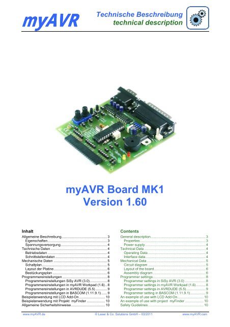
myAVRTechnische Beschreibungtechnical descriptionmyAVR Board MK1Version 1.60InhaltAllgemeine Beschreibung............................................... 3Eigenschaften............................................................. 3Spannungsversorgung................................................ 4Technische Daten .......................................................... 4Betriebsdaten ............................................................. 4Schnittstellendaten ..................................................... 4Mechanische Daten ....................................................... 5Schaltplan................................................................... 5Layout der Platine....................................................... 6Bestückungsplan ........................................................ 6Programmereinstellungen .............................................. 8Programmereinstellungen SiSy AVR (3.0).................. 8Programmereinstellungen in myAVR Workpad (1.6) .. 8Programmereinstellungen in AVRDUDE (5.5) ............ 9Programmereinstellungen in BASCOM (1.11.9.1) ...... 9Beispielanwendung mit LCD Add-On........................... 10Beispielanwendung mit Projekt myFinder ................... 10Allgemeine Sicherheitshinweise................................... 10ContentsGeneral description........................................................ 3Properties ................................................................... 3Power supply.............................................................. 4Technical Data ............................................................... 4Operating Data ........................................................... 4Interface data.............................................................. 4Mechanical Data ............................................................ 5Circuit diagram ........................................................... 5Layout of the board..................................................... 6Assembly diagram ...................................................... 6Programmer settings...................................................... 8Programmer settings in SiSy AVR (3.0) ..................... 8Programmer settings in myAVR Workpad (1.6).......... 8Programmer settings in AVRDUDE (5.5).................... 9Programmer setting in BASCOM (1.11.9.1)................ 9An example of use with LCD Add-On........................... 10An example of use with project myFinder ................... 10Safety Guidelines......................................................... 10www.myAVR.de © Laser & Co. Solutions GmbH – 03/2011 www.myAVR.com
- Seite 3 und 4: Technische Beschreibung / technical
- Seite 5 und 6: Technische Beschreibung / technical
- Seite 7 und 8: Technische Beschreibung / technical
- Seite 9 und 10: Technische Beschreibung / technical
<strong>myAVR</strong>Technische Beschreibungtechnical description<strong>myAVR</strong> <strong>Board</strong> <strong>MK1</strong><strong>Version</strong> <strong>1.60</strong>InhaltAllgemeine Beschreibung............................................... 3Eigenschaften............................................................. 3Spannungsversorgung................................................ 4Technische Daten .......................................................... 4Betriebsdaten ............................................................. 4Schnittstellendaten ..................................................... 4Mechanische Daten ....................................................... 5Schaltplan................................................................... 5Layout der Platine....................................................... 6Bestückungsplan ........................................................ 6Programmereinstellungen .............................................. 8Programmereinstellungen SiSy AVR (3.0).................. 8Programmereinstellungen in <strong>myAVR</strong> Workpad (1.6) .. 8Programmereinstellungen in AVRDUDE (5.5) ............ 9Programmereinstellungen in BASCOM (1.11.9.1) ...... 9Beispielanwendung mit LCD Add-On........................... 10Beispielanwendung mit Projekt myFinder ................... 10Allgemeine Sicherheitshinweise................................... 10ContentsGeneral description........................................................ 3Properties ................................................................... 3Power supply.............................................................. 4Technical Data ............................................................... 4Operating Data ........................................................... 4Interface data.............................................................. 4Mechanical Data ............................................................ 5Circuit diagram ........................................................... 5Layout of the board..................................................... 6Assembly diagram ...................................................... 6Programmer settings...................................................... 8Programmer settings in SiSy AVR (3.0) ..................... 8Programmer settings in <strong>myAVR</strong> Workpad (1.6).......... 8Programmer settings in AVRDUDE (5.5).................... 9Programmer setting in BASCOM (1.11.9.1)................ 9An example of use with LCD Add-On........................... 10An example of use with project myFinder ................... 10Safety Guidelines......................................................... 10www.<strong>myAVR</strong>.de © Laser & Co. Solutions GmbH – 03/2011 www.<strong>myAVR</strong>.com
Technische Beschreibung / technical description <strong>myAVR</strong> <strong>Board</strong> <strong>MK1</strong>, <strong>Version</strong> <strong>1.60</strong> 3/10Allgemeine BeschreibungDas <strong>myAVR</strong> <strong>Board</strong> <strong>MK1</strong> verfügt über einen RISC AVR-Mikrocontroller (ATmega8) der Firma ATMEL. Auf dem<strong>Board</strong> sind ein SP12 kompatibler LPT-Programmer und einRS232 (COM/V24) Port integriert. Des Weiteren befindensich bereits einige typische Ein- und Ausgabegeräte wiezum Beispiel Potentiometer, Schalter, Schallwandler undLEDs auf dem <strong>Board</strong>. Ebenfalls auf dem Bord, ein analogerLichtsensor zum Einsatz unterschiedlicher Helligkeitsgrade.Die für das <strong>Board</strong> vorgesehenen Controller gehören zurReihe Mega-AVRs und verfügen über alle wesentlichenBaugruppen. Das System ist nach didaktischenGesichtspunkten für Ausbildung und Selbststudiumkonzipiert.Eigenschaften• Lern- und Experimentierboard für ATMEL Mikrocontrollerder ATmega-Reihe (8/168/328)sowie der ATtiny-Reihe (48/88)• integrierter SP12 kompatibler Programmer mit Bustreiber74HC125• Mit Controller und typischen Ein- und Ausgabegeräten• Analoger Fotosensor zum Experimentieren mitunterschiedlichen Helligkeitsgraden• Programmierbar in Assembler, C, C++ und BASCOM• als Bausatz geeignet (kein SMD)• Duale Spannungsversorgung über LPT oder externeSpannungsversorgung• Einfache Handhabung, keine Spezialkabel nötig• Buchsenleiste für den Anschluss von weiteren Add-Ons• Leiterplatte gebohrt, verzinnt, Industriefertigung, robust,bedrucktGeneral descriptionThe <strong>myAVR</strong> <strong>Board</strong> <strong>MK1</strong> is equipped with a RISC AVRmicrocontroller(ATmega8) from ATMEL. A SP12compatible LPT-programmer and a RS232 (COM/V24)port are integrated on the board. In addition there areother typical input and output devices on the board likea Potentiometer, switches, a speaker and LEDs. Alsoon the board a photo sensor for the use of differentdegrees of brightness.The designated controllers for the board belong to theMEGA-AVRs.The system is designed for education andprivate study.Properties• Suitable for educational use and to perform individualexperiments with ATMEL microcontrollers of theAtmega row (8/168/328) and the ATtiny-row (48/88)• Integrated SP12 compatible programmer with busdriver 74HC125• With controller and typical input and output devices• Analog photo sensor (photoconductive cell) toexperiment with different degrees of brightness• Programmable in Assembler, C, C++ and BASCOM• Suitable as an assembly kit (no SMD)• Power supply via LPT or external PSU• Easy handling, no special cables necessary• Pin header to connect to other Add-Ons• Printed circuit board pre-drilled, tin-plated, industrialproduction, solid, printedRS232 Port (COM)KommunikationcommunicationISP Port (LPT)ProgrammierungprogrammingRISC µControllerµTaster/Schalter (digital)µ buttons / switch (digital)Externe Spannungsversorgungexternal power supplyPotenziometer (analog)Potenziometer (analog)Schallwandler (Frequenzen)electric buzzer (frequenzies)Lichtsensor (analog)Photo sensor (analog)LEDs (digital/analog)Ausgabegeräteoutput devicesEingabegeräteinput devicesErweiterungsbuchseAdd-On socketPinbelegung der ErweiterungsbuchsePin assignments of the Add-On-socket1 = Port D.22 = Port D.33 = Port D.44 = Port D.55 = Port D.66 = Port D.77 = Port B.08 = Port B.19 = Port B.210 = Port B.311 = Port B.412 = Port B.513 = 5 V14 = GND15 = Port C.016 = Port C.117 = Port C.218 = Port C.319 = Port C.420 = Port C.5www.<strong>myAVR</strong>.de © Laser & Co. Solutions GmbH - 03/2011 www.<strong>myAVR</strong>.com
Technische Beschreibung / technical description <strong>myAVR</strong> <strong>Board</strong> <strong>MK1</strong>, <strong>Version</strong> <strong>1.60</strong> 4/10SpannungsversorgungWir empfehlen beim Anschluss weitererModule (Add-Ons) die Verwendung des<strong>myAVR</strong> Netzteils• stabilisiert, kurzschlussfest• Eingang: 230 VAC / 50 Hz; 10,2 W• Ausgang: 9 V DC• Mit Anschlussbuchse für das <strong>myAVR</strong><strong>Board</strong>Power supplyWe recommend the <strong>myAVR</strong> PSUtogether with <strong>myAVR</strong> LPT <strong>Board</strong>• stabilized, short circuit proteced• input: 230 VAC / 50 Hz; 10.2 W• output: 9 V DC• with connector for the <strong>myAVR</strong><strong>Board</strong>Technische DatenTechnical DataBetriebsdatenOperating DataVersorgungsspannung: empfohlen 9V stabilisierteGleichspannungSupply Voltage:9 V stabilized DC voltagerecommendedBetriebsstrom: 10-50 mA typisch ohne weitereVerbraucherbis 150mA bei Verwendung desLCD Add-OnsOperating Current : 10-50 mA typical without otherloadsuntil 150 mA with usage of theLCD Add-OnBetriebsspannung: 3,3 – 5,3 V Operating Voltage: 3.3 – 5.3 VBetriebstemperatur: 0 °C bis +30 °C Operating Temperature: 0 °C up to +30 °CLagertemperatur: -20 °C bis +70 °C Storage Temperature: -20 °C up to +70 °CSchnittstellendatenInterface dataLPT-Programmer: SUB-D, Stecker, 25polig LPT-Programmer: D-SUB connector 25 pinPinbelegung: 17, 18, 19, 20, 21 = Masse4, 5, 6, 7, 8 =Versorgungsspannung2 = SCK3 = RESET9 = MOSI11 = MISOpin configuration: 17, 18, 19, 20, 21 = ground4, 5, 6, 7, 8 = supply voltage2 = SCK3 = RESET9 = MOSI11 = MISOProgrammierkabel:Standard LPT- Verlängerung,25polig SUB-D, Buchsen-Stecker,max. 1,8 mprogramming cable:Standard serial expansioncable, D-SUB connector 25pin, max. 1,8 mCOM/RS232: SUB-D, Stecker, 9polig COM/RS232: D-SUB connector 9 pinPinbelegung: 2 =RXD, 3 =TXD, 7 =RTS, 8 =CTS pin configuration: 2 =RXD, 3 =TXD, 7 =RTS, 8=CTSKommunikationskabel: Standard Nullmodemkabel, max.3mcommunication cable:Standard null modem cable,max. 3mErweiterungsport: Buchsenleiste, 20polig, 1reihig,Rastermaß 2,54 mmPinbelegung: 1 = Port D.2 7 = Port B.02 = Port D.3 8 = Port B.13 = Port D.4 9 = Port B.24 = Port D.5 10 = Port B.35 = Port D.6 11 = Port B.46 = Port D.7 12 = Port B.513 = <strong>Board</strong>spannung14 = Masse15 = Port C.016 = Port C.117 = Port C.218 = Port C.319 = Port C.420 = Port C.5Extension board: pin header, 20 pin, one´s lineup, grid dimensions 2.54 mmpin configuration: 1 = Port D.2 7 = Port B.02 = Port D.3 8 = Port B.13 = Port D.4 9 = Port B.24 = Port D.5 10 = Port B.35 = Port D.6 11 = Port B.46 = Port D.7 12 = Port B.513 = board voltage14 = ground15 = Port C.016 = Port C.117 = Port C.218 = Port C.319 = Port C.420 = Port C.5www.<strong>myAVR</strong>.de © Laser & Co. Solutions GmbH - 03/2011 www.<strong>myAVR</strong>.com
Technische Beschreibung / technical description <strong>myAVR</strong> <strong>Board</strong> <strong>MK1</strong>, <strong>Version</strong> <strong>1.60</strong> 5/10Mechanische DatenMechanical DataAbmaße (L x B x H) ca. 100 mm x 90 mm x 15mmDimensions(L X W X H)~ 100 mm x 90 mm x 15mmMasse ca. 70 g Weight ~ 70 gRastermaß 2,54 mm Grid dimensions 2.54 mmLeiterplattenmaterial: FR8, 1,5 mm Dicke, 0,35 µm CuAuflage, zweiseitig, Lötstoppmaske,verzinnt, Dokumentationsdruck,bleifreiPrinted circuit board: FR8, 1,5 mm Thickness, 0.35µm Cu Edition, two lines up,Soldering stop mask, tin-plated,documentation print, lead freeSchaltplan/ Circuit diagram<strong>myAVR</strong> <strong>Board</strong> <strong>MK1</strong> <strong>Version</strong> <strong>1.60</strong>www.<strong>myAVR</strong>.deRTSCTS98761010K+5V25242322212019181716151413121110987654321D70V+5V0V+5V1µF+1µF+V+V-2613+5V16155VGNDC1+C1-C2+C2-450V147138T1OUTT2OUTR1INR2INT1INT2INR1OUTR2OUT1110129TxDRxDMAX2320VCTS RTS12543218974HC125N+5V7 14GND VCC0VIC2P0V4674HC125N51312 1174HC125N374HC125N12+5VD8D9D10D11S1+1µF0V+22pF22pF1µF100nFQ1+5V10µH100nF 100nF0V+5V0V+5V1210K12121202291078MEGA8-PPC6(/RESET) PC0(ADC0)PC1(ADC1)PC2(ADC2)PC3(ADC3)AREF PC4(ADC4/SDA)PC5(ADC5/SCL)AVCCAGNDPD0(RXD)PD1(TXD)PD2(INT0)PD3(INT1)PB6(XTAL1/TOSC1) PD4(XCK/T0)PD5(T1)PB7(XTAL2/TOSC2) PD6(AIN0)PD7(AIN1)VCCGND123ResetRxDTxDPB0(ICP)PB1(OC1A)PB2(SS/OC1B)PB3(MOSI/OC2)PB4(MISO)PB5(SCK)23242526272823456111213141516171819121212121212331 20V+5V1 2POT1POT20VSpeaker1 20VLED11,2K0VLED21,2K0VLED312123434S212120V0V+5V2211PHOTO10K0V12+5V1,2KLED40V123456123456+5V1234561,2K0V0VP01P02P03P04P05P06P07P08P09P10P11P12P13P14P15P16P17P18P19P20SV21212100nF+5V220µF+D17806OUT INGND100nF47µF+B2STROMSTECKER210Vwww.<strong>myAVR</strong>.de © Laser & Co. Solutions GmbH - 03/2011 www.<strong>myAVR</strong>.com
Technische Beschreibung / technical description <strong>myAVR</strong> <strong>Board</strong> <strong>MK1</strong>, <strong>Version</strong> <strong>1.60</strong> 6/10Layout der Platine/ Layout of the boardobentopLayoutlayoutuntenbottomBestückungsplan/ Assembly diagramwww.<strong>myAVR</strong>.de © Laser & Co. Solutions GmbH - 03/2011 www.<strong>myAVR</strong>.com
Technische Beschreibung / technical description <strong>myAVR</strong> <strong>Board</strong> <strong>MK1</strong>, <strong>Version</strong> <strong>1.60</strong> 7/10bestücktes <strong>Board</strong> <strong>MK1</strong> / equipped board <strong>MK1</strong>www.<strong>myAVR</strong>.de © Laser & Co. Solutions GmbH - 03/2011 www.<strong>myAVR</strong>.com
Technische Beschreibung / technical description <strong>myAVR</strong> <strong>Board</strong> <strong>MK1</strong>, <strong>Version</strong> <strong>1.60</strong> 8/10ProgrammereinstellungenProgrammer settingsProgrammereinstellungen SiSy AVR (3.0) Programmer settings in SiSy AVR (3.0)Legen Sie in SiSy ein neues Projekt an. Im <strong>myAVR</strong>ProgTool legen Sie die Hardwareinstellungen festgelegt.In SiSy you have to apply a new project. Yourhardwaresettings will be defined in “<strong>myAVR</strong> ProgTool”.Sie erreichen die Hardwareeinstellungen, in einembereits angelegten SiSy-Projekt auch, in dem Siefolgende Schritte absolvieren:MenüpunktProjekt/Definieren oder Objekt-Kontextmenü (rechteMaustaste) Definieren Registerkarte Extras (AVR) Schaltfläche (Button) Hardware einstellenYou can reach the hardwaresettings also, if you haveapplied a SiSy-project, then do the following steps:menu„Projekt/Definieren or ”Objekt-Kontextmenü“ right mousebutton „Definieren“ index card „Extras (AVR)“ button „Hardware einstellen“Programmereinstellungen in <strong>myAVR</strong> Workpad (1.6) Programmer settings in <strong>myAVR</strong> Workpad (1.6)Menüpunkt Extras / Einstellungenmenu „Extras / Einstellungen"www.<strong>myAVR</strong>.de © Laser & Co. Solutions GmbH - 03/2011 www.<strong>myAVR</strong>.com
Technische Beschreibung / technical description <strong>myAVR</strong> <strong>Board</strong> <strong>MK1</strong>, <strong>Version</strong> <strong>1.60</strong> 9/10Programmereinstellungen in AVRDUDE (5.5) Programmer settings in AVRDUDE (5.5)Kommandozeilecommand lineD:\> avrdude.exe -p ATtiny12 -e -csp12 -Uflash:w:"test.hex":i -P lpt1Programmereinstellungen in BASCOM (1.11.9.1) Programmer setting in BASCOM (1.11.9.1)Menüpunkt Options/Programmermenu „Options/Programmer“www.<strong>myAVR</strong>.de © Laser & Co. Solutions GmbH - 03/2011 www.<strong>myAVR</strong>.com
Technische Beschreibung / technical description <strong>myAVR</strong> <strong>Board</strong> <strong>MK1</strong>, <strong>Version</strong> <strong>1.60</strong> 10/10Beispielanwendung mit LCD Add-OnAn example of use with LCD Add-OnBeispielanwendung mit Projekt myFinderAn example of use with project myFinderAllgemeine SicherheitshinweiseGrundsätzlich ist das <strong>myAVR</strong> <strong>Board</strong> <strong>MK1</strong> nur zum Einsatzunter Lern- und Laborbedingungen konzipiert. Es ist nichtvorgesehen und nicht dimensioniert zur Steuerung realerAnlagen. Bei vorschriftsmäßigem Anschluss und Betriebtreten keine lebensgefährlichen Spannungen auf. BeachtenSie trotzdem die Vorschriften, die beim Betriebelektrischer Geräte und Anlagen Gültigkeit haben. Wirversichern, dass die Leiterplatte durch den Herstellergetestet wurde. Für fehlerhaften und/odervorschriftswidrigen Einsatz des <strong>Board</strong>s übernehmen wirkeine Garantie.Safety GuidelinesThe <strong>myAVR</strong> <strong>Board</strong> <strong>MK1</strong> is designed for educational andexperimental use only. It is not intended and notdimensioned to control real industrial facilities. At correctuse there will not occur extremely dangerous voltages.Nevertheless, be aware of general guidelines for usingelectronic devices. We assure that the PCB has beentested by the producer. For incorrect use and/orapplication contrary to technical regulations we are notliable.Die aktuellsten Dokumente zum <strong>myAVR</strong> <strong>Board</strong> <strong>MK1</strong> finden Sie unter www.<strong>myAVR</strong>.de im Downloadbereich.You can find the latest documents for the <strong>myAVR</strong> <strong>Board</strong> <strong>MK1</strong> on our homepage www.<strong>myAVR</strong>.com under „Download“.Abbildungen können vom Inhalt abweichen. Änderungen im Sinne des technischen Fortschrittes behält sich derHersteller vor.Images may vary from the content. The manufacturers retains changes in terms of technical advances.www.<strong>myAVR</strong>.de © Laser & Co. Solutions GmbH - 03/2011 www.<strong>myAVR</strong>.com


