BG 65, 50 - 150 W
BG 65, 50 - 150 W
BG 65, 50 - 150 W
- Keine Tags gefunden...

Sie wollen auch ein ePaper? Erhöhen Sie die Reichweite Ihrer Titel.
YUMPU macht aus Druck-PDFs automatisch weboptimierte ePaper, die Google liebt.
advanced motion solutionsDIN EN ISO 9001:2000DIN EN ISO 14001U L®Brushless DC-MotorsBürstenlose GleichstrommotorenSeries <strong>BG</strong> Baureihe <strong>BG</strong>
ForewordVorwortTo Our Valued Customers,Alcatel Dunkermotoren is a world class leader inhigh quality motion control solutions to meet theever increasing demands for cost effective andreliable drive solutions.Our comprehensive product range offers theflexibility to provide customized solutions as well asstandardized components.The catalog represents Dunkermotoren´s years ofengineering excellence.The Dunkermotoren Team will continue to utilizeour outstanding engineering and industrial capabilitiesto meet the requirements helping you tosucceed.Wishing you great success in your business.Nikolaus GräfGeneral ManagerUnseren geschätzten Kunden,als führender Hersteller der Antriebstechnik bietetAlcatel Dunkermotoren wirtschaftliche, zuverlässigeund qualitativ hochwertige Antriebskomplettlösungen.Aufgrund unseres umfassenden Produktspektrumskönnen wir mit einem hohen Maß anFlexibilität standardisierte Komponenten sowieauch kundenspezifische Lösungen anbieten.In diesem Katalog finden Sie eine Auswahl unsererinnovativen und richtungsweisenden Produkte.Das Dunkermotoren-Team wird auch in Zukunft allsein Wissen und Können einbringen, um dieAnforderungen zu erfüllen, die Sie noch erfolgreichermachen.Ich wünsche Ihnen weiterhin alles Gute und vielErfolg.Nikolaus GräfGeneral Manager
ContentInhalt23467Foreword / VorwortContent / InhaltWhy Dunkermotoren? / Gute GründeOur Product Range / Unser modulares LieferprogrammApplications / Anwendungen891011Brushless DC Motors <strong>BG</strong> / Bürstenlose Gleichstrommotoren <strong>BG</strong><strong>BG</strong> Selection Guide / <strong>BG</strong>-AuswahlübersichtTechnical Information / Technische InformationenEngineering Reference / Auslegung des Antriebs12141618202224262830<strong>BG</strong> 31 KI, 6 W<strong>BG</strong> 40, 15 - 30 W<strong>BG</strong>E 40/ <strong>BG</strong>E 3004/ <strong>BG</strong>E 6007<strong>BG</strong> 44 SI, 20 - 40 W<strong>BG</strong> <strong>65</strong>, <strong>50</strong> - 1<strong>50</strong> W<strong>BG</strong> <strong>65</strong> SI, <strong>50</strong> - 1<strong>50</strong> W<strong>BG</strong> <strong>65</strong> CI, <strong>50</strong> - 1<strong>50</strong> W<strong>BG</strong> <strong>65</strong> KI, 60 - 220 W<strong>BG</strong> 83, 200 - 310 W<strong>BG</strong>E 9010313236Gears / GetriebePLGSG404244<strong>50</strong>Brakes for BLDC Motors / Bremsen für <strong>BG</strong> MotorenIncremental Encoders for BLDC Motors / Inkrementalgeber für <strong>BG</strong> MotorenAccessories / ZubehörRepresentatives and Distributors / Vertretungen© 11/2004Alcatel SEL AGComponents DivisionDunkermotorenPrinted in Germany3Foreword Content Vorwort Inhalt
Why Dunkermotoren?Gute GründeTechnology & Customer FocusAt Dunkermotoren, research and developmentis a way of life. The company is activelycommitted to developing key technologies andproducts that are crucial for its growth. Nextgenerationtechnology is in the R&D pipelinetoday.Product development is focused on innovationsto help our customers create value and differentiatethemselves from competitors.Innovation und KundenorientierungDunkermotoren ist stolz darauf, vielfach neueIndustrie-Standards in der Antriebsbranchegeschaffen zu haben. Es ist der Ansprucheines Technologieführers, der Konkurrenzimmer einen entscheidenden Schritt vorauszu sein.Unsere innovativen marktorientierten Antriebslösungenmachen unsere Kunden noch erfolgreicherund helfen ihnen, sich mit ihrenProdukten positiv von denen der Mitbewerberabzusetzen.Quality Assurance & ReliabilityOne of Dunkermotoren´s primary objectivesis to offer outstanding quality. In 1991Dunkermotoren became the world´s firstmanufacturers of small motors to becertified to ISO 9001. In the meantime,Dunkermotoren has won numerous qualityawards.Dunkermotoren regards quality as a comprehensiveprocess involving all activities in the factory.Our products are manufactured exclusively inGermany on highly automated production lines.Failure mode and effects analysis during designand development, and fully automated testingintegrated in the production line ensure auniformly high level of quality.Flexibility, Delivery Performance &Complete Motion SolutionsStandardized motors, gears and modularaccessories are available with a higher degreeof flexibility to address specific requirements incomplete motion solutions. For the customer,this means better control of quality, reducedinventory and reduced production time. If anydetail does not entirely meet your requirements,our R&D department will make modificationsat short notice.Dunkermotoren’s Modular System anoptimized logistics, enables prompt deliveryfor both stock and customized products.Delivery time for stock items are 2-5 daysand for customized solutions are 3-7 weeks.Qualität & ZuverlässigkeitAntriebslösungen höchster Qualität sind beiDunkermotoren eine Selbstverständlichkeit,fest verankert in Unternehmensgrundsätzenund Philosophie. Bereits 1991 wurdeDunkermotoren als weltweit erster Herstellervon Kleinmotoren nach ISO 9001 zertifiziert. Inder Zwischenzeit folgten zahlreiche weitereAuszeichnungen und Zertifizierungen vonKunden und Vereinigungen.Dunkermotoren versteht Qualität als einenganzheitlichen Prozess, der sämtliche betrieblichenTätigkeiten umfasst. Dunkermotorenproduziert ausschließlich in Deutschland;hochautomatisierte Fertigungsstrecken undvollautomatische Qualitätskontrollen in denFertigungslinien gewährleisten ein konstanthohes Qualitätsniveau.Flexibilität, Lieferperformance undumfassende AntriebslösungenDunkermotoren´s Produktpalette ist so aufgebaut,dass sich mit standardisierten Motorenund einem modular aufgebauten Zubehör einehohe Flexibilität für umfassende Antriebslösungenergibt. Und sollten sie einmal einProdukt benötigen, dass es noch nicht gibt,dann entwickelt unsere Konstruktionsabteilungkundenspezifische Sonderlösungenin kürzester Zeit.Aufgrund der konsequenten Verwirklichungdes Baukastensystems und einer ausgeklügeltenProduktionslogistik bietet Dunkermotoreneine bessere Lieferperformance als diemeisten Mitbewerber, bei Lagerprodukten(Ø 2-5 Tage) wie auch bei kundenspezifischenLösungen (Ø 3-7 Wochen).4
Our Product RangeUnser modulares LieferprogrammDC-MotorsBrushless DC Motors, Series <strong>BG</strong>Rated voltage..... 12-360 VDCRated speed ...... 2700-3<strong>65</strong>0 rpmTorque ............. 9-110 NcmPower rating...... 6-300 WDC Motors, Series GR/GRated voltage..... 3-220 VDCRated speed ...... 1<strong>50</strong>0-10000 rpmTorque ............. 0.47-<strong>65</strong> NcmPower rating...... 3-220 WGleichstrommotorenBürstenlose Gleichstrommotoren, Baureihe <strong>BG</strong>Nennspannung....... 12-360 VDCNenndrehzahl........ 2700-3<strong>65</strong>0 min -1Drehmoment......... 9-110 NcmAbgabeleistung...... 6-300 WGleichstrommotoren, Baureihe GR/GNennspannung....... 3-220 VDCNenndrehzahl........ 1<strong>50</strong>0-10000 min -1Drehmoment......... 0,47-<strong>65</strong> NcmAbgabeleistung...... 3-220 WAC-MotorsAC Motors, Series KD/DRRated voltage..... 230-400 VAC, <strong>50</strong>HzPower rating...... 2-86 WTorque ............. 0.75-31.5 NcmVariants............. 2/4 polePositioning Drives, Series DRated voltage..... 230 V, <strong>50</strong> HzRated speed ...... 11-52 rpmTorque ............. 3-20 NmPower rating...... <strong>50</strong>-220 WWechselstrommotorenDreh- u. Wechselstrommot., Baureihe KD/DRNennspannung....... 230-400 VAC, <strong>50</strong>HzAbgabeleistung...... 2-86 WDrehmoment......... 0,75-31,5 NcmVarianten.............. 2/4 poligJalousie- u. Stellantriebe, Baureihe DNennspannung....... 230 V, <strong>50</strong> HzNenndrehzahl........ 11-52 min -1Drehmoment......... 3-20 NmAbgabeleistung...... <strong>50</strong>-220 WAccessoriesPlanetary Gearboxes, Series PLGContinuous torque...0.3-60 NmRatio.....................4:1-512:1Worm Gearboxes, Series SGContinuous torque...1-15 NmRatio.....................5:1-80:1Brakes, Series EEncoders, Series RE/TG/MEElectronic Control Systems, Series <strong>BG</strong>E/RSAnbautenPlanetengetriebe, Baureihe PLGDauerdrehmoment..........0,3-60 NmUntersetzungsverhältnis...4:1-512:1Schneckengetriebe, Baureihe SGDauerdrehmoment..........1-15 NmUntersetzungsverhältnis...5:1-80:1Bremsen, Baureihe EInkrementalgeber, Baureihe RE/TG/MERegelelektroniken, Baureihe <strong>BG</strong>E/RS6
ApplicationsAnwendungenSome ApplicationsBeispiele für AnwendungenFactory and Industrial AutomationIndustrielle AutomatisierungMedical and Laboratory TechnologyMedizin- und LabortechnikMechanical EngineeringMaschinenbauPackaging and Food MachineryVerpackungs- und LebensmittelmaschinenDoor and Window AutomationAutomatische Türen und FensterMechanical HandlingMechanischer Gebrauch und FördertechnikOffice MachineryAutomaten und BüroausstattungPumpsAutomotive IndustriesCustomized SolutionsThe impossible takes a little longer! – customerspecificsolutions from Dunkermotoren! Takeadvantage of the full range of knowledge andexperience of our drive specialists. We willdevelop the best possible drive unit solution foryou–innovative, objective and application-oriented.7Pumpen und KompressorenFahrzeugbauKundenspezifische LösungenGeht nicht gibt´s nicht! – KundenspezifischeLösungen von Dunkermotoren! Profitieren sievom Know-how des Antriebsspezialisten. Wirrealisieren zielgerichtet, innovativ und anwendungsorientiertdie bestmögliche Antriebseinheitfür Sie.Our Product Range Applications Lieferprogramm Anwendungen
Brushless DC Motors <strong>BG</strong>Bürstenlose Gleichstrommotoren <strong>BG</strong>The Dunkermotoren <strong>BG</strong> range of brushless, direct currentmotors (EC motors) are notable for:• Very long life• High efficiency• Highly dynamic acceleration• Good regulation characteristics• Wide speed range• High power density• Maintenance-free• Robust design• Integral Hall sensors for rotor position• Low moment of inertia• High degree of protection• Winding insulation - Class E or B• Ferrite and neodymium magnetsDunkermotoren´s bürstenlose Gleichstrommotoren (EC-Motoren) der Baureihe <strong>BG</strong> zeichnen sich aus durch:• Sehr hohe Lebensdauer• Hoher Wirkungsgrad• Hochdynamische Beschleunigung• Gute Regelbarkeit• Einen großen Drehzahlbereich• Hohe Leistungsdichte• Wartungsfreiheit• Robusten Aufbau• Integrierten Hallsensoren zur Erfassung der Rotorlage• Geringes Trägheitsmoment• Hohe Schutzart• Wicklungsisolation nach Isolierstoffklasse E bzw. B• Ferrit- und NeodymmagneteThese electronically-commutated DC motors can becombined with control electronics, gearboxes, andencoders in a modular system to provide a flexible,adaptable, market-oriented solution.The newly developed <strong>BG</strong> 44 and <strong>BG</strong> <strong>65</strong> ranges areespecially noteworthy – they have fully integrated electronicsfor a wide variety of functions and an unbeatableprice-performance ratio.Further information and graphical representations ofthe commutation logic forthese motors are availableupon request.You will find furthertechnical information,layout data, and informationon the selection of motors andgearboxes on page 10, andon the Internet at:www.dunkermotoren.comDie elektronisch kommutierten Gleichstrommotorenergeben im Baukastensystemzusammen mit Regel-Elektroniken,Getrieben,Bremsen und Istwertgebernein flexibles,anpassungsfähigesund marktorientiertesSortiment.Besonders hervorzuhebensind dabei dieNeuentwicklungen derBaureihen <strong>BG</strong> 44 und<strong>BG</strong> <strong>65</strong>, die durch integrierteElektroniken für vielfältigeFunktionen sowie einemunschlagbaren Preis-Leistungsverhältnisbestechen.Informationen und grafischeDarstellungen bezüglichder Kommutierungslogik der Motorensind auf Anfrage erhältlich.Weitere technische Informationen,Auslegungen und Informationenzur richtigen Auswahl vonMotoren und Getrieben erhaltensie auf S. 10 und im Internet beiwww.dunkermotoren.de8
<strong>BG</strong> Selection Guide with Page References<strong>BG</strong>-Auswahlmöglichkeiten mit Seitenverweisen<strong>BG</strong>31x2040x2544x2540x<strong>50</strong>44x<strong>50</strong><strong>65</strong>x25.<strong>65</strong>x<strong>50</strong><strong>65</strong>x7583x5583x55S6 W2 Ncm19 W5 Ncm20 W6 Ncm32 W8 Ncm40 W11 Ncm60 W20 Ncm100 W30 Ncm140 W40 Ncm195 W62 Ncm311 W110 NcmMotors without controllerMotoren ohne Elektronikp. 12 p. 14p. 18 p. 14 p. 18 p. 20 p. 20 p. 20 p. 28 p. 28ELECTRONIC CONTROL SYSTEMSKI (1Q)Integral Electronic CommutatorKommutierungselektronik integriert/ REGEL-ELEKTRONIKENp. 12p. 26 p. 26 p. 26SI (2Q /4Q)Integral Servo ControllerServoregler integriertp. 18 p. 18 p. 22 p. 22p. 22CI (4Q)Integral Motion Controller &CAN InterfaceMotionregler &CAN-Schnittstelle integriertp. 24 p. 24 p. 24<strong>BG</strong>E 40 (2Q)Controller attachedRegelelektronik angebautp. 16p. 16<strong>BG</strong>E 3004 (1Q)External controllerExterne Regelelektronik<strong>BG</strong>E 6007 (1Q)External controllerExterne Regelelektronikp. 16 p. 16 p. 16 p. 16 p. 16p. 17 p. 17 p. 17 p. 17<strong>BG</strong>E <strong>65</strong>05 (4Q)External controllerExterne Regelelektronikp. 20 p. 20 p. 20<strong>BG</strong>E 9010 (4Q)External controllerwith optional CAN InterfaceExterne Regelelektronikoptional mit CAN-Schnittstellep. 30 p. 30INCREMENTAL ENCODERS / INKREMENTALGEBERRE 30RE 56p. 42 p. 42 p. 42 p. 42 p. 42p. 42p. 42p. 42p. 42p. 42p. 42p. 42p. 42p. 42GEARBOXES / GETRIEBEPLG 32 (0.40 – 4 Nm) p. 32PLG 42 K (0.70 – 3 Nm)p. 32 p. 32 p. 32 p. 32PLG 42 S (3.5 – 14 Nm)p. 32 p. 32 p. 32 p. 32PLG 52 (1.2 – 24 Nm)p. 32 p. 32 p. 32 p. 32 p. 32 p. 32 p. 32PLG 52 H (1.2 – 24 Nm)p. 32 p. 32 p. 32 p. 32 p. 32 p. 32 p. 32PLG 60 (5 – 25 Nm)p. 32 p. 32 p. 32PLG 70 (5 – 60 Nm)p. 32 p. 32 p. 32 p. 32 p. 32SG 62(1 – 1.5 Nm)p. 36 p. 36 p. 36 p. 36SG 80(2 – 4 Nm)p. 36 p. 36 p. 36SG 120 (8 – 15 Nm)p. 36 p. 36 p. 36 p. 36 p. 36BRAKES / BREMSENE 38 RE 46 AE 90 RE 100 RE 100 AACCESSORIES / ZUBEHÖRMiscellaneous / Verschiedenesp. 40 p. 40 p. 40 p. 40 p. 40p. 40 p. 40 p. 40 p. 40 p. 40 p. 40 p. 40p. 40 p. 40 p. 40 p. 40 p. 40 p. 40 p. 40 p. 40 p. 40p. 40 p. 40 p. 40 p. 40 p. 40 p. 40 p. 40 p. 40 p. 40p. 40 p. 40 p. 40 p. 40 p. 40 p. 40 p. 40 p. 40 p. 40p. 44 p. 44 p. 44 p. 44 p. 44 p. 44 p. 44 p. 44 p. 44 p. 44Standard/StandardOn request/auf Anfrage9
Technical InformationTechnische InformationPERFORMANCE DATAPerformance figures given in the tables are measured in accordancewith VDE530/ EN60034. These figures are based on the assumptionthat the motor is freestanding and that certain other theoreticalconditions are fulfilled. In a real application, the rated torque of amotor will often be considerably higher. For this reason, the datatables quote the rated torquemeasured according to VDE/ EN2.8 70 7000(lower value) and also the torquewith the motor mounted on a 2.4 60 6000ηthermally conducting steel platewith the dimensions 105 x 105 x 2 <strong>50</strong> <strong>50</strong>00 N = f (M)10 mm (value in brackets).For many applications, it is sufficientlyaccurate to take the mostimportant data from the motorcharacteristic diagrams and datatables. Although tolerances andtemperature influences are nottaken into account, the data isaccurate enough for approximatecalculations. The degree ofprotection quoted relates only to the housing – adequate sealing of theshaft is the responsibility of the customer.- Nominal voltage U N (VDC)The DC voltage that is applied to the commutation electronics asa system supply voltage. All rated data in our catalogs are withreference to this voltage. Motor applications are, however, notrestricted to this voltage.- Rated torque M N (Ncm)The torque that can be produced by the motor, operating continuously,in an ambient temperature of 20°C.- Rated speed n N (min -1 )The speed of the motor when it is operating at rated torque (6).- Rated current I N (A)The current drawn from a DC source when the motor is operatingat rated torque (7).- Starting current I A (A)The current required to produce the starting torque. For motorswith electronics, the starting current may be higher than thepermissible peak current (4).- Starting torque M A (Ncm)The maximum torque the motor can produce (2).- Rated power P N (W)The output power which the motor can produce continuously; it iscalculated from rated speed and rated torque.- Moment of inertia of rotor J R (gcm 2 )The moment of inertia of the rotor is the factor that determines thedynamic properties of a motor.- Peak current I max (A)The maximum current for electronics or motors with integralelectronics (5).- Max. permissible voltage range U max (VDC)The minimum and maximum permissible input voltage forelec- tronics or motors with integral electronics.- Recommended speed control range n max (min-1)The regulated speed range within which rotor position sensing byHall sensors ensures a smooth torque curve. As a rule, this rangecan be extended by installing a rotary encoder.The data in this catalog contain product specifications, but are not aguarantee of particular properties. The stated values are subject totolerances. Any supplementary information and safety instructionsgiven in the operating manual must be observed with no exceptions.We reserve the right to make technical changes and to restrictavailability.current/Strom I (A)1.61.20.80.40efficiency/Wirkungsgrad η (%)403020100rated speed/Drehzahl n (rpm)400030002000Continuous operationDauerbetrieb10LEISTUNGSDATENIn den Datentabellen sind die Werte gemessen nach VDE530/EN60034 angegeben. Diese Werte basieren auf der Annahmeeines freistehenden Motors und auf weiteren theoretischenGegebenheiten. Im reellen Einsatzfall liegt das Nenndrehmomentdes Motors oftmals wesentlich höher. Deshalb sind in den Datentabellendie Nenndrehmomentegemessen nach VDE/ ENCyclic operationZyklischer BetriebDestroying operationZerstörende BetriebszuständeJ = f (M)10000-0.8 0 0.8 1.6M2.4 N 3.2 4 4.8 5.6 6.4 7.2 8 Ncm(niedrigere Angabe) sowiegemessen bei Anbringungeiner thermisch leitendenStahlplatte der Größe 105 x105 x 10 mm (Angabe inKlammern) aufgeführt.Den Motordiagrammen undDatentabellen können die fürviele Anwendungen wichtigstenDaten entnommen werden.Obwohl Toleranzen undTemperatureinflüsse nichtberücksichtigt sind, reichen dieWerte für überschlagsmässigeBetrachtungen aus. Die angegebenen Schutzarten beziehen sich nur aufdie Gehäuse. Die Abdichtung der Welle ist vom Kunden vorzunehmen.- Nennspannung U N (VDC)Die Gleichspannung, die als Systemversorgungsspannung an dieKommutierungselektronik angelegt wird. Auf diese Spannung beziehensich alle Nenndaten in den Katalogen. Die Motoranwendung istjedoch nicht auf diese Spannung beschränkt.- Nenndrehmoment M N (Ncm)Das Moment, das der Motor bei einer Umgebungstemperatur von20°C im Dauerbetrieb abgeben kann.- Nenndrehzahl n N (min -1 )Die Drehzahl, die sich bei Abgabe des Nenndrehmoments einstellt (6).- Nennstrom I N (A)Der Strom, der der Gleichspannungsquelle entnommen wird, wennder Motor bei Nenndrehmoment betrieben wird (7).- Anlaufstrom I A (A)Der Strom, der fließt, um das Anlaufmoment zu erzeugen. BeiMotoren mit Elektronik kann der Anlaufstrom höher sein als derzulässige Spitzenstrom (4).- Anlaufmoment M A (Ncm)Das Moment, welches der Motor maximal erzeugen kann (2).- Nennleistung P N (W)Die Abgabeleistung des Motors, welche er dauerhaft erzeugenkann; berechnet aus Nenndrehzahl und Nenndrehmoment.- Läufermassenträgheitsmoment J R (gcm 2 )Massenträgheitsmoment des Rotors und bestimmende Größe fürdie dynamischen Eigenschaften des Motors.- Spitzenstrom I max (A)Der maximal zulässige Strom bei Elektroniken oder Motoren mitintegrierter Elektronik (5).- Max. zulässiger Spannungsbereich U max (VDC)Die minimal und maximal zulässige Eingangsspannung beiElektroniken oder Motoren mit integrierter Elektronik.- Empfohlener Drehzahlregelbereich n max (min -1 )Der Drehzahlregelbereich in dem bei Rotorlageerkennung durchHallsensoren ein glatter Drehmomentverlauf steuerbar ist. DurchAnbringung eines Inkrementalencoders kann dieser Bereich in derRegel erweitert werden.Die Angaben in diesem Katalog enthalten Spezifikationen derProdukte, nicht aber die Zusicherung von Eigenschaften. Die genanntenWerte unterliegen Toleranzen. Die im Betriebshandbuch angegebenenErgänzungen und Sicherheitshinweise sind unbedingt zu beachten.Liefermöglichkeiten und technische Änderungen vorbehalten.
Engineering Reference Auslegung des AntriebsMOTOR CHARACTERISTIC DIAGRAMS- Speed curve (blue)This curve shows the speed characteristic at constant voltage. Itsend points are the no-load speed n 0 (1) and the theoretical startingtorque M A (2).- Current curve (black)The current curve shows the relationship between current andtorque. Its end points are the no-load current I 0 (3) and the startingcurrent I A (4).- Efficiency curve (green)The efficiency is the relationship between the mechanical power outputand the electrical power input.The curve shows the efficiency with the motor in cold condition; asthe motor warms up, the curve shifts accordingly.- Rated torque M N / Starting torque M maxThe rated torque (red) is the limit of the continuous operationregion (shaded blue). In the region between the rated torque andthe maximum permissible torque, the motor must only be usedintermittently (shaded orange). Operating conditions above the maximumpermissible torque result in demagnetization of the permanentmagnets (shaded red).MOTORDIAGRAMME- Drehzahlkennlinie (blau)Diese Kennlinie beschreibt das Drehzahlverhalten bei konstanterSpannung. Deren Endpunkte zeigen die Leerlaufdrehzahl n 0 (1) unddas theoretische Anlaufmoment M A (2).- Stromkennlinie (schwarz)Die Stromkennlinie stellt die Äquivalenz von Strom und Drehmomentdar. Deren Endpunkte zeigen den Leerlaufstrom I 0 (3) und denAnlaufstrom I A (4).- Wirkungsgradkennlinie (grün)Der Wirkungsgrad beschreibt das Verhältnis von abgegebenermechanischer Leistung zu aufgenommener elektrischer Leistung.Die Kennlinien beziehen sich auf den Kaltzustand des Motors undverschieben sich entsprechend bei zunehmender Erwärmung desMotors.- Nenndrehmoment M N , Anlaufdrehmoment M maxDas Kriterium Nenndrehmoment (rot) begrenzt den Dauerbetriebsbereich(blau schattiert). Im Bereich zwischen Nenndrehmomentund max. zulässigem Drehmoment darf der Motor nur kurzzeitigbetrieben werden (orange schattiert). Betriebszustände über demmax. zulässigen Drehmoment führen zur Entmagnetisierung derDauermagneten (rot schattiert).ENGINEERING REFERENCEIn the wide range of Dunkermotoren products, you will find a suitabledrive for almost any requirement in powers ranging from 1 –310 Watt. Please note also our other product lines and catalogs(DC commutator motors, AC motors).The following points should be taken into account when selectingmotors and gearboxes:- Which type of operation is required (continuous, intermittent orperiodic operation)?- What is the working life expected of the motor?- What torque and speeds are required?- How much space is available for the motor?- How high is the available voltage? DC or AC?- Are there special environmental conditions (temperature,humidity, vibration, ...)?- To what degree can heat from the motor be disposed of?- Are there exceptional axial and radial shaft loads to consider?- What demands are made of the motor control electronics?- Is the motor to be controlled online via a bus system?- Do you need a brake, an encoder or a non-reversing device?When laying out a suitable motor, determining the required torqueplays a decisive role in avoiding thermal overload of the motor in service.In the assembly of a drive system consisting of motor and controlelectronics, it is important to ensure that permissible values forthe motor are not exceeded by outputs from the electronics.Depending on the speed of rotation required, a motor or a motorgearboxcombination may be selected. The choice of a reductiongearbox will largely depend on the recommended maximum torquein continuous operation. For intermittent duty, loading above therated torque is possible.When choosing a motor after deciding on the gearbox, the followingapplies:M motor = M gearbox / (i x η)We will be pleased to carry out a precise adaptation of a motor toyour service conditions.11AUSLEGUNG DES ANTRIEBSIn Dunkermotoren´s breiter Produktpalette finden Sie für nahezujede Anforderung einen passenden Antrieb im Leistungsbereich von1 – 310 Watt. Bitte beachten Sie auch unsere weiterenProduktlinien und –kataloge (DC Kollektormotoren, Wechselstrommotoren).Folgende Punkte sollten bei der Auswahl von Motor und Getriebeberücksichtigt werden:- Welche Betriebsart liegt vor (Dauer-, Kurzzeit- oderAussetzbetrieb)?- Welche Lebensdauer wird gefordert?- Welches Drehmoment und welche Drehzahl werden benötigt?- Wie viel Raum ist für den Motor verfügbar?- Wie hoch ist die verfügbare Spannung? Gleich- oderWechselspannung?- Gibt es besondere Umgebungseinflüsse (Temperatur,Feuchtigkeit, Vibration, ...)?- In welchem Umfang wird die Motorwärme abgeleitet?- Müssen außergewöhnliche axiale und radiale Wellenbelastungenberücksichtigt werden?- Welchen Steuerungsanforderungen muss dieSteuerungselektronik des Motors genügen?- Werden die Motoren online über ein Bussystem angesteuert?- Benötigen Sie eine Bremse, einen Encoder oder eineRücklaufsperre?Für die Auslegung des geeigneten Motors spielt die Ermittlung deseffektiven Drehmomentes die entscheidende Rolle, um zuverhindern, dass der Motor im Betrieb thermisch überlastet wird.Für die Zusammenstellung eines Antriebssystems aus Motor undBetriebselektronik ist zu berücksichtigen, dass die für den Motorzulässigen Werte durch die Elektronik nicht überschritten werden.Je nach gewünschter Drehzahl wird man sich für entweder für einenMotor oder einen Getriebemotor entscheiden. Die Wahl desUntersetzungsgetriebes richtet sich nach dem empfohlenen maximalenDrehmoment bei Dauerbetrieb. Bei kurzzeitigem Betrieb sindauch Belastungen über dem Nennmoment möglich.Zur Auswahl des Motors nach Festlegung des Getriebes gilt:M Motor = M Getriebe / (i x η)Gerne erfolgt auf Aufrage eine exakte Anpassung des Motors anIhre Betriebsbedingungen.Technical Information Technische Informationen
<strong>BG</strong> 31 KI, 6 WDimensions in mm / Maßzeichnung in mmCharacteristic diagram / BelastungskennlinienIn accordance with EN 60034Belastungskennlinien gezeichnet nach VDE 5302.82.421.67060<strong>50</strong>4070006000<strong>50</strong>004000N = f (M)ηJ = f (M)ϑ R =20°C∆ϑ W = 100K2.82.421.67060<strong>50</strong>4070006000<strong>50</strong>00N = f (M)4000ηJ = f (M)ϑ R =20°C∆ϑ W = 100Kcurrent/Strom I (A)1.20.80.40efficiency/Wirkungsgrad η (%)3020100rated speed/Drehzahl n (rpm)3000200010000M-0.8 0 0.8 1.6 N 2.4 3.2 4 4.8 5.6 6.4 7.2 8 Ncmcurrent/Strom I (A)1.20.80.40efficiency/Wirkungsgrad η (%)3020100rated speed/Drehzahl n (rpm)3000200010000M-0.8 0 0.8 1.6 N 2.4 3.2 4 4.8 5.6 6.4 7.2 8 Ncm<strong>BG</strong> 31 x 20, 12V<strong>BG</strong> 31 x 20, 24V13<strong>BG</strong> 31 KI, 6 W
<strong>BG</strong> 40, 15 - 30 WVersions of <strong>BG</strong> 40 / Ausführungen <strong>BG</strong> 40Controllers / Regelelektroniken- motor without controller / Motor ohne Elektronik- with controller attached (<strong>BG</strong>E40) / mit angebauter Steuerungselektronik (<strong>BG</strong>E40)- with external controller (<strong>BG</strong>E3004;<strong>BG</strong>E6007) /mit externer Steuerungselektronik (<strong>BG</strong>E3004;<strong>BG</strong>E6007)With incremental encoder / mit InkrementalgeberWith gearbox / Als GetriebemotorWith brake / Als BremsmotorP./S.141616423140Standard/StandardOn request/auf Anfrage• Highly dynamic 3-phase EC motor• With 4-pole neodymium magnet• Additional power electronics are neededto run this motor• On request, this motor can be manufacturedwith different windings• Hochdynamischer 3-strängiger EC-Motor• Mit 4-poligem Neodymmagnet• Für den Betrieb dieser Motoren ist einezusätzliche Leistungselektronik notwendig• Diese Motoren werden auf Anfrage auchmit anderen Wicklungen hergestelltData/ LeistungsdatenRated voltage/NennspannungContinuous rated speed/NenndrehzahlContinuous rated torque/NenndrehmomentContinuous current/NennstromStarting torque/AnlaufmomentStarting current/AnlaufstromRotor inertia/TrägheitsmomentWeight of motor/Motorgewichtrpm *)Ncm *)A *)Ncm **)A **)gcm 2kg<strong>BG</strong> 40x2512 VDC24 VDC271033404.7 (5.6*** ) 4.6 (5.5*** )2.41.313.416.85.93.934340.420.42<strong>BG</strong> 40x<strong>50</strong>12 VDC24 VDC301036407.6 (9.1*** ) 8,0 (9.6*** )3.92.12437.410.48.464640.60.6*) ∆ϑ w =100 K; **) ϑ R =20°C;***) Continuous rated torque depends on heat dissipation from the motor (see p. 10)Das Nenndrehmoment ist abhänig von der Wärmeabführung des Motors (siehe S. 10)14
<strong>BG</strong> 40, 15 - 30 WDimensions in mm / Maßzeichnung in mmCharacteristic diagram / BelastungskennlinienIn accordance with EN 60034Belastungskennlinien gezeichnet nach VDE 53076706070006000J = f (M)ϑ R =20°C∆ϑ W = 100K76706070006000ϑ R =20°C∆ϑ W = 100K54<strong>50</strong>40<strong>50</strong>00N = f (M)4000η54<strong>50</strong>40<strong>50</strong>00N = f (M)4000ηJ = f (M)current/Strom I (A)3210efficiency/Wirkungsgrad η (%)3020100rated speed/Drehzahl n (rpm)300020001000M0N-2 0 2 4 6 8 10 12 14 16 18 20 Ncmcurrent/Strom I (A)3210efficiency/Wirkungsgrad η (%)3020100rated speed/Drehzahl n (rpm)300020001000M0N-2 0 2 4 6 8 10 12 14 16 18 20 Ncm<strong>BG</strong> 40 x 25, 12V<strong>BG</strong> 40 x 25, 24Vcurrent/Strom I (A)14121086420efficiency/Wirkungsgrad η (%)7060<strong>50</strong>403020100rated speed/Drehzahl n (rpm)70006000<strong>50</strong>00N = f (M)4000300020001000M0N-4 0 4 8 12 16 20 24 28 32 36 40 Ncm<strong>BG</strong> 40 x <strong>50</strong>, 12VηJ = f (M)ϑ R =20°C∆ϑ W = 100Kcurrent/Strom I (A)1514121086420efficiency/Wirkungsgrad η (%)7060<strong>50</strong>403020100rated speed/Drehzahl n (rpm)70006000<strong>50</strong>00N = f (M)4000300020001000M0N-4 0 4 8 12 16 20 24 28 32 36 40 Ncm<strong>BG</strong> 40 x <strong>50</strong>, 24Vηϑ R =20°C∆ϑ W = 100KJ = f (M)<strong>BG</strong> 40, 15 - 30 W
<strong>BG</strong> 40 Controller RegelelektronikenData/ LeistungsdatenDesign/BauartOperating voltage/BetriebsspannungVoltage range/Max. zulässiger SpannungsbereichContinuous current/Max. zulässiger DauerstromPeak current/Max. zulässiger SpitzenstromAmbient temperature/UmgebungstemperaturWeight/GewichtVDCVDCAA°Ckg<strong>BG</strong>E 40attached/angebaut12 ... 4011,2 ... 44434- 10 ... + 400.04<strong>BG</strong>E 3004external/extern12 ... 4011,2 ... 44434- 10 ... + 400.085• With Controllers <strong>BG</strong>E40/ <strong>BG</strong>E3004, speed control pulsewidthmodulation (PWM)• There is an integral potentiometer for setting the speed• Two connection leads can be used to provide both astart/stop and a clockwise/counter-clockwise function• As an option, the <strong>BG</strong>E 40 can be suppliedwith a fifth connection lead; this is used toprovide an external target voltage forsetting the speed• By supplying an analog target voltage inthe range 0...+10 V, the speed of rotationcan be set in a range from <strong>50</strong>0 rpm to<strong>50</strong>00 rpm• Lower speeds, down to ca. 200 rpm, arepossible where less smooth rotation canbe tolerated• Various protection functions, such as low-voltage cut-off,reverse-polarity protection, over-temperature cut-off, andstall protection, guarantee high operational reliability• Die Drehzahlregelung des Motors erfolgt bei den Elektroniken<strong>BG</strong>E40/ <strong>BG</strong>E3004 über Pulsweitenmodulation (PWM)• Die Drehzahl kann über ein integriertes Potentiometer festvorgegeben werden• Über zwei Anschlusslitzen kann sowohl eineStart/Stopp- als auch eine Rechts/Links-Umschaltung erfolgen• Optional kann die <strong>BG</strong>E 40 auch mit einerfünften Anschlusslitze zur Drehzahlvorgabemit einer externen Sollwertspannunggeliefert werden• Durch Vorgabe einer analogenSollwertspannung von 0...+10 V kann dieDrehzahl im Bereich von <strong>50</strong>0 rpm bis <strong>50</strong>00rpm eingestellt werden• Kleinere Drehzahlen bis ca. 200 rpm sind miteingeschränkter Rundlaufgenauigkeit möglich• Verschiedene Schutzeinrichtungen wie Unterspannungsabschaltung,Verpolschutz, Übertemperaturabschaltung undBlockierschutz garantieren eine hohe BetriebssicherheitPlease note that, for the <strong>BG</strong>E 3004, the matching motorconnector must also be ordered. For further technical dataand information on terminal assignment, please go towww.dunkermotoren.com (downloads).Bitte beachten Sie, dass bei der <strong>BG</strong>E 3004 der Gegensteckerzum Motor mitbestellt werden muss. Weitere technischeDaten sowie Informationen zur Anschlussbelegung finden Siebei www.dunkermotoren.de (downloads).Dimensions in mm / Maßzeichnung <strong>BG</strong>E 4016
<strong>BG</strong> 40 Controller RegelelektronikenData/ LeistungsdatenDesign/BauartOperating voltage/BetriebsspannungVoltage range/Max. zulässiger SpannungsbereichContinuous current/Max. zulässiger DauerstromPeak current/Max. zulässiger SpitzenstromAmbient temperature/UmgebungstemperaturWeight/GewichtVDCVDCAA°Ckg<strong>BG</strong>E 6007external/extern2410 ... 60725- 10 ... + 400.25• To protect it against mechanical damage, Controller<strong>BG</strong>E 6007 is installed in a compact plastic housing• The power supply to the controller is +24 VDC• Normally, the motor supply is +24 VDC, but, ifnecessary, any voltage in the range+10 V...+60 VDC can be employed• The current limit can be set with apotentiometer, or by using a controlvoltage (0...+12 V)• In addition, there is a potentiometer forsetting the minimum current and anotherfor the maximum current• Speed regulation uses signals from Hallsensors in the motor; this frequency isevaluated by the controller• As standard, there are inputs forswitching the direction of rotation andstart/stop• Reversing the motor at full power is possible, as is abrupt,short-circuit braking• One output signal indicates if the motor is rotating• The <strong>BG</strong>E 6007 has circuits to protect against overloading,overvoltage, and shortingPlease note that, for the <strong>BG</strong>E 6007, the matching motorconnector must also be ordered. For further technical dataand information on terminal assignment, please go towww.dunkermotoren.com (downloads).Dimensions / Maßzeichnung <strong>BG</strong>E 600775 mm45 mm105 mm17• Die Regelelektronik <strong>BG</strong>E 6007 ist zum Schutz vor mechanischerBeschädigung in einem kompakten Kunststoffgehäuseuntergebracht• Die Spannungsversorgung der Schaltung erfolgt über +24 VDC• Die Motorversorgung erfolgt im Normalfallebenfalls über +24 VDC, kann aber beiBedarf auch im gesamten Spannungsbereichvon +10 V...+60 VDC erfolgen• Die Strombegrenzung lässt sich über einPotentiometer oder über eineSteuerspannung (0...+12 V) einstellen• Zusätzlich kann über je ein Potentiometerder minimale und der maximale Stromwertvorgegeben werden• Die Drehzahlregelung erfolgt über Hallsignaledes Motors, deren Frequenz vom Reglerausgewertet wird• Standardmäßig sind Eingänge für Rechts-/Links-Umschaltungund Start/Stopp vorhanden• Das Reversieren des Motors auf vollem Lauf ist ebensomöglich wie das abrupte Abbremsen durch Kurzschlussbremsung• Ein Ausgang zeigt an, ob sich der Motor dreht• Die <strong>BG</strong>E 6007 ist durch verschiedene Schutzeinrichtungengegen Überlastung, Überspannungen oder Kurzschluss gesichertBitte beachten Sie, dass bei der <strong>BG</strong>E 6007 der Gegensteckerfür den Motor mitbestellt werden muss. Weitere technischeDaten sowie Informationen zur Anschlussbelegung finden Sie inder Betriebsanleitung bei www.dunkermotoren.de (downloads).<strong>BG</strong>E 6007 Pin locations / AnschlussbelegungSM1SM2SM3SM4SM5SM6SM7SM8SM9Mot-BMot-AMot-CGNDH1H2H3+12V-DCMin-activSV1SV2SV3SV4SV5SV6SV7SV8SV9SV1010...60 VDC Motor supply24 VDC Control circuitryGNDSTP - OUT max. <strong>50</strong> mAI - POT-minI - POT-mI - POT-maxSpeedRevRun<strong>BG</strong>E 40, <strong>BG</strong>E 3004, <strong>BG</strong>E 6007
<strong>BG</strong> 44 SI, 20 - 40 WCONTROLLERINTEGRATEDVersions of <strong>BG</strong> 44 / Ausführungen <strong>BG</strong> 44 P./S.Controllers / Regelelektroniken- integral 2Q controller (<strong>BG</strong>44SI) / mit integrierter 2Q-Steuerungselektronik (<strong>BG</strong>44SI)- with external 2Q controller (<strong>BG</strong>E3004, <strong>BG</strong>E6007) /mit externer 2Q-Steuerungselektronik (<strong>BG</strong>E3004, <strong>BG</strong>E6007)- motor without controller / Motor ohne ElektronikWith gearbox / Als GetriebemotorWith brake / Als BremsmotorStandard/StandardOn request/auf Anfrage1816-3140• Highly dynamic 3-phase EC motor with 4-pole neodymiummagnet• With integral speed-control electronics for 2-quadrant drive• As standard, the target speed can be set using a 0...+10Vanalog voltage input• There are two further digital inputs forswitching the direction of rotation andstart/stop• In addition, there are two digital outputs,which provide a pulsed output with12 impulses per revolution (e.g. formonitoring position and speed) and anerror signal• Customer-specific versions, with specialterminal assignment or special windings toadapt the working point to the operatingvoltage, are available upon request• With its completely closed housing made of black anodizedaluminum, the motor can be supplied, on request, withdegree of protection IP <strong>65</strong>• The high power density and compact design coupled with avery favorable price/performance ratio make this motorsuitable for numerous applicationsFor further technical data and information on terminalassignment, please see the operating manual atwww.dunkermotoren.com (downloads).• Hochdynamische 3-strängige EC-Motoren mit 4-poligemNeodymmagnet• Mit integrierter Drehzahlregelelektronik für 2-Quadrantenbetrieb• Die Drehzahlsollwertvorgabe erfolgt standardmäßig übereinen Analogspannungseingang 0...+10V• Über zwei weitere digitale Eingänge lassensich die Drehrichtung rechts und links sowieStart/Stopp ansteuern• Außerdem werden zwei digitale Ausgängeherausgeführt, womit ein Pulsausgang mit12 Impulsen pro Umdrehung (z.B. fürPositions- und Geschwindigkeitsüberwachung)und eine Fehlermeldung zur Verfügung stehen• Kundenspezifische Ausführungen mit speziellerSteckerbelegung oder Sonderwicklungen zurAnpassung des Arbeitspunktes an die Betriebsspannungsind auf Anfrage möglich• Durch sein komplett geschlossenes Gehäuse aus schwarzeloxiertem Aluminium kann der Motor auf Wunsch mitSchutzart IP <strong>65</strong> geliefert werden• Die hohe Leistungsdichte und kompakte Bauform gestattetbei einem günstigen Preis/Leistungsverhältnis den Einsatz inzahlreichen AnwendungenWeitere technische Daten sowie Informationen zur Anschlussbelegungfinden Sie in der Betriebsanleitung beiwww.dunkermotoren.de (downloads).Data/ LeistungsdatenRated voltage/NennspannungContinuous rated speed/rpmNenndrehzahl*)Continuous rated torque/NcmNenndrehmoment*)Continuous current/ANennstrom*)Starting torque/NcmAnlaufmoment**)Peak current/AMax. zulässiger Spitzenstrom**)Rotor inertia/gcmTrägheitsmoment2Weight of motor/kgMotorgewichtVoltage range/VDCMax. zulässiger SpannungsbereichRecommended speed control range/rpmEmpfohlener Drehzahlregelbereich<strong>BG</strong>44x25 SI<strong>BG</strong>44x<strong>50</strong> SI24 VDC 24 VDC32003<strong>50</strong>06 (7.2*** )11 (13*** )1.542.813133.53.534630.470.6611 ... 4411 ... 44400 ... <strong>50</strong>00400 ... <strong>50</strong>00*) ∆ϑ w =100 K; **) ϑ R =20°C;***) Continuous rated torque depends on heat dissipation from the motor (see p. 10)Das Nenndrehmoment ist abhänig von der Wärmeabführung des Motors (siehe S. 10)18
<strong>BG</strong> 44 SI, 20 - 40 WDimensions in mm / Maßzeichnung in mmCharacteristic diagram / BelastungskennlinienIn accordance with EN 60034Belastungskennlinien gezeichnet nach VDE 5304.23.63560048004000ϑ R =20°C∆ϑ W = 100KJ = f (M)4.23.63560048004000N = f (M)ϑ R =20°C∆ϑ W = 100KJ = f (M)2.432002.43200current/Strom I (A)1.81.20.60rated speed/Drehzahl n (rpm)24001600800N = f (M)0-2 0 2 4M6 N8 10 12 14 16 18 20 Ncmcurrent/Strom I (A)1.81.20.60rated speed/Drehzahl n (rpm)240016008000-2 0 2 4 6 8M10 N 12 14 16 18 20 Ncm<strong>BG</strong> 44 x 25 SI, 24V19<strong>BG</strong> 44 x <strong>50</strong> SI, 24V<strong>BG</strong> 44 SI, 20 - 40 W
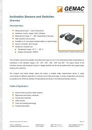
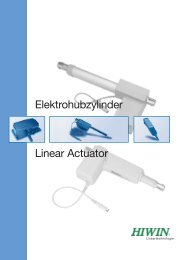
<strong>BG</strong> <strong>65</strong>, <strong>50</strong> - 1<strong>50</strong> WVersions of <strong>BG</strong> <strong>65</strong> / Ausführungen <strong>BG</strong> <strong>65</strong> P./S.Controllers / Regelelektroniken- motor without controller (<strong>BG</strong><strong>65</strong>) / Motor ohne Elektronik (<strong>BG</strong><strong>65</strong>)- integral electronic commutator (<strong>BG</strong><strong>65</strong>Kl) /2026mit integrierter Kommutierungelektronik (<strong>BG</strong><strong>65</strong>Kl)- integral 4Q servo controller (<strong>BG</strong><strong>65</strong>Sl) /22mit integrierter 4Q-Steuerungselektronik (<strong>BG</strong><strong>65</strong>Sl)- integral 4Q motion controller and CAN interface (<strong>BG</strong><strong>65</strong>Cl) /24mit integrierter 4Q-Steuerungselektronik und CAN-Schnittstelle (<strong>BG</strong><strong>65</strong>Cl)- with external 4Q servo controller (<strong>BG</strong>E<strong>65</strong>05) /20mit externem 4Q-Servoregler (<strong>BG</strong>E<strong>65</strong>05)Housing / Gehäuse- extruded smooth body / Glattes Strangpressprofilgehäuse- extruded fin body / Geripptes StrangpressprofilgehäuseWith incremental encoder / Mit Inkrementalgeber21-42With gearbox / Als Getriebemotor31With brake / Als Bremsmotor40Standard/StandardOn request/auf Anfrage• Highly dynamic 3-phase EC motor with 10-pole neodymiummagnet• With its completely closed housing made of black anodizedaluminum, the motor can be supplied, onrequest, with degree of protection IP <strong>65</strong>• The high power density and compact designcoupled with a very favorable price/performance ratio make this motor suitablefor numerous applications• Custom versions are available with windingsfor higher voltages• The <strong>BG</strong> <strong>65</strong> must be connected to externalpower electronics using 3 leads for controllingthe motor and a further 5 leads for signalingthe rotor position• On request, the motor can be supplied with the externalelectronic controller <strong>BG</strong>E <strong>65</strong>05. Technically, thiscorresponds to the integral electronics SI• Hochdynamische 3-strängige EC-Motoren mit 10-poligemNeodymmagnet• Durch sein komplett geschlossenes Gehäuse aus schwarzeloxiertem Aluminium kann der Motor mit hoherSchutzart, auf Wunsch bis IP <strong>65</strong>, geliefert werden• Die hohe Leistungsdichte und kompakte Bauformgestattet bei einem guten Preis /Leistungsverhältnisden Einsatz in zahlreichen Anwendungen• In Sonderausführung sind Wicklungen für höhereSpannungen möglich• Beim <strong>BG</strong> <strong>65</strong> erfolgt der Anschluss zu einerextern angeordneten Leistungselektronik über 3Anschlusslitzen zur Motoransteuerung und über5 Anschlusslitzen zur Erfassung der Rotorlage• Für größere Projekte ist der Motor auch mit der externenSteuerungselektronik <strong>BG</strong>E <strong>65</strong>05 erhältlich. Diese entsprichttechnisch der integrierten Elektronik SIData/ LeistungsdatenRated voltage/NennspannungContinuous rated speed/NenndrehzahlContinuous rated torque/NenndrehmomentContinuous current/NennstromStarting torque/AnlaufmomentStarting current/AnlaufstromRotor inertia/TrägheitsmomentWeight of motor/Motorgewichtrpm *)Ncm *)A *)Ncm **)A **)gcm 2kg<strong>BG</strong> <strong>65</strong>x25 <strong>BG</strong> <strong>65</strong>x<strong>50</strong> <strong>BG</strong> <strong>65</strong>x7524 VDC 24 VDC 42 VDC31003100286017 (21*** )26 (31*** )40 (47*** )45.64.59716333083.3130136721281720.871.31.8*) ∆ϑ w =100 K; **) ϑ R =20°C;***) Continuous rated torque depends on heat dissipation from the motor (see p. 10)Das Nenndrehmoment ist abhänig von der Wärmeabführung des Motors (siehe S. 10)20
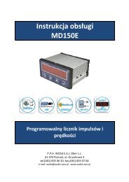
<strong>BG</strong> <strong>65</strong>, <strong>50</strong> - 1<strong>50</strong> WDimensions in mm / Maßzeichnung in mmCharacteristic diagram / BelastungskennlinienIn accordance with EN 60034Belastungskennlinien gezeichnet nach VDE 530353070607000N = f (M)6000ϑ R =20°C∆ϑ W = 100K35307060N = f (M)70006000J = f (M)ϑ R =20°C∆ϑ W = 100K25<strong>50</strong><strong>50</strong>00ηJ = f (M)25<strong>50</strong><strong>50</strong>00η2040400020404000current/Strom I (A)1510<strong>50</strong>efficiency/Wirkungsgrad η (%)3020100rated speed/Drehzahl n (rpm)3000200010000M-10 0 10 N20 30 40 <strong>50</strong> 60 70 80 90 100 Ncmcurrent/Strom I (A)1510<strong>50</strong>efficiency/Wirkungsgrad η (%)3020100rated speed/Drehzahl n (rpm)300020001000M0N-20 0 20 40 60 80 100 120 140 160 180 200 Ncm<strong>BG</strong> <strong>65</strong> x 25, 24V<strong>BG</strong> <strong>65</strong> x <strong>50</strong>, 24Vcurrent/Strom I (A)7060<strong>50</strong>403020100efficiency/Wirkungsgrad η (%)7060<strong>50</strong>403020100rated speed/Drehzahl n (rpm)N = f (M)70006000<strong>50</strong>0040003000200010000M N-30 0 30 60 90 120 1<strong>50</strong> 180 210 240 270 300 Ncm<strong>BG</strong> <strong>65</strong> x 75, 42VηJ = f (M)ϑ R =20°C∆ϑ W = 100K21<strong>BG</strong> <strong>65</strong>, <strong>50</strong> - 1<strong>50</strong> W
<strong>BG</strong> <strong>65</strong> SI, <strong>50</strong> - 1<strong>50</strong> WCONTROLLERINTEGRATEDVersions of <strong>BG</strong> <strong>65</strong> SI / Ausführungen <strong>BG</strong> <strong>65</strong> SIControllers / Regelelektroniken- integral 4Q servo controller (<strong>BG</strong><strong>65</strong>Sl) /mit integrierter 4Q-Steuerungselektronik (<strong>BG</strong><strong>65</strong>Sl)Housing / Gehäuse- extruded smooth body / Glattes Strangpressprofilgehäuse- extruded fin body / Geripptes StrangpressprofilgehäuseWith incremental encoder / Mit InkrementalgeberWith gearbox / Als GetriebemotorWith brake / Als BremsmotorP./S.2223-423140Standard/StandardOn request/auf Anfrage• Highly dynamic 3-phase EC motor with 10-pole neodymiummagnet• With integral servo controller for 4-quadrant drive• As standard, the target speed can be setusing a 0...+10V analog voltage input• There are two further digital inputs forselecting the four operating conditions:rotation clockwise/ counter-clockwise,controller block, and stop with holding torque• In addition, there are digital outputs, whichprovide a pulsed output with 15 impulses perrevolution and a direction of rotation signal(e.g. for monitoring position and speed), andan error signal• Two fixed speeds, and acceleration and de-accelerationramps can be stored in memory• The motor is supplied as standard with a 12-pin connector(IP<strong>65</strong>). Where larger quantities are involved, we can supplya version with connection leads, which is 17mm shorter(IP<strong>50</strong>). There is no connector on the side of the motorFor further technical data and information on terminalassignment, please see the operating manual atwww.dunkermotoren.com (downloads).• Hochdynamische 3-strängige EC-Motoren mit 10-poligemNeodymmagnet• Mit integriertem Servocontroller für 4-Quadrantenbetrieb• Die Drehzahlsollwertvorgabe erfolgt standardmäßigüber einen Analogspannungseingang 0...+10V• Über zwei weitere digitale Eingänge lassen sichdie vier Betriebszustände Drehrichtung rechts,Drehrichtung links, Reglersperre und Stopp mitHaltemoment anwählen• Außerdem werden digitale Ausgänge herausgeführt,womit ein Pulsausgang mit 15 Impulsenpro Umdrehung sowie ein Drehrichtungssignal(z.B. für Positions- und Geschwindigkeitsüberwachung)und ein Störungssignal zur Verfügung stehen• Das Abspeichern von 2 festen Geschwindigkeiten sowie vonHochlauf- und Bremsrampe ist möglich• Der Motor ist standardmäßig mit einem 12-poligenAnschlussstecker (IP<strong>65</strong>) versehen. Bei größeren Bedarfsfällenkann auch eine um 17mm kürzere Litzenversion desMotors geliefert werden (IP<strong>50</strong>). Der seitliche Stecker entfälltdannWeitere technische Daten sowie Informationen zur Anschlussbelegungfinden Sie in der Betriebsanleitung beiwww.dunkermotoren.de (downloads).Data/ LeistungsdatenRated voltage/NennspannungContinuous rated speed/rpmNenndrehzahl*)Continuous rated torque/NcmNenndrehmoment*)Continuous current/ANennstrom*)Starting torque/NcmAnlaufmoment**)Peak current/AMax. zulässiger Spitzenstrom**)Rotor inertia/gcmTrägheitsmoment2Weight of motor/kgMotorgewichtVoltage range/VDCMax. zulässiger SpannungsbereichRecommended speed control range/rpmEmpfohlener Drehzahlregelbereich<strong>BG</strong> <strong>65</strong>x25 SI <strong>BG</strong> <strong>65</strong>x<strong>50</strong> SI <strong>BG</strong> <strong>65</strong>x75 SI24 VDC 24 VDC 42 VDC310017 (21*** )49727720.9520 ... 3070 ... <strong>50</strong>00310026 (31*** )5.6163271281.320 ... 3070 ... <strong>50</strong>00286040 (47*** )4.5330271721.820 ... <strong>50</strong>70 ... <strong>50</strong>00*) ∆ϑ w =100 K; **) ϑ R =20°C;***) Continuous rated torque depends on heat dissipation from the motor (see p. 10)Das Nenndrehmoment ist abhänig von der Wärmeabführung des Motors (siehe S. 10)22
<strong>BG</strong> <strong>65</strong> SI, <strong>50</strong> - 1<strong>50</strong> WDimensions in mm / Maßzeichnung in mmCharacteristic diagram / BelastungskennlinienIn accordance with EN 60034Belastungskennlinien gezeichnet nach VDE 530353070607000N = f (M)6000ϑ R =20°C∆ϑ W = 100K35307060N = f (M)70006000J = f (M)ϑ R =20°C∆ϑ W = 100K25<strong>50</strong><strong>50</strong>00ηJ = f (M)25<strong>50</strong><strong>50</strong>00η2040400020404000current/Strom I (A)current/Strom I (A)1510<strong>50</strong>7060<strong>50</strong>403020100efficiency/Wirkungsgrad η (%)efficiency/Wirkungsgrad η (%)30201007060<strong>50</strong>403020100rated speed/Drehzahl n (rpm)rated speed/Drehzahl n (rpm)3000200010000M-10 0 10 N20 30 40 <strong>50</strong> 60 70 80 90 100 Ncm<strong>BG</strong> <strong>65</strong> x 25 SI, 24VN = f (M)70006000<strong>50</strong>004000300020001000η0M N-30 0 30 60 90 120 1<strong>50</strong> 180 210 240 270 300 Ncm<strong>BG</strong> <strong>65</strong> x 75 SI, 42VJ = f (M)ϑ R =20°C∆ϑ W = 100Kcurrent/Strom I (A)231510<strong>50</strong>efficiency/Wirkungsgrad η (%)3020100rated speed/Drehzahl n (rpm)300020001000M0N-20 0 20 40 60 80 100 120 140 160 180 200 Ncm<strong>BG</strong> <strong>65</strong> x <strong>50</strong> SI, 24V<strong>BG</strong> <strong>65</strong> SI, <strong>50</strong> - 1<strong>50</strong> W
<strong>BG</strong> <strong>65</strong> CI, <strong>50</strong> - 1<strong>50</strong> WCONTROLLERINTEGRATEDVersions of <strong>BG</strong> <strong>65</strong> CI / Ausführungen <strong>BG</strong> <strong>65</strong> CI P./S.Controllers / Regelelektroniken- integral 4Q motion controller and CAN interface (<strong>BG</strong><strong>65</strong>CI) /24mit integrierter 4Q-Steuerungselektronik und CAN-Schnittstelle (<strong>BG</strong><strong>65</strong>CI)Housing / Gehäuse- extruded smooth body / Glattes Strangpressprofilgehäuse- extruded fin body / Geripptes StrangpressprofilgehäuseWith incremental encoder / Mit Inkrementalgeber25-42With gearbox / Als Getriebemotor31With brake / Als Bremsmotor40Standard/StandardOn request/auf Anfrage• Highly dynamic 3-phase EC motor with 10-pole neodymiummagnet• Integral Motion Controller for 4-quadrantdrive with dynamic positioning• CAN interface• By using the integral Motion Controllerand an integral rotor-position encoder, evenvery complex motion profiles can be performed• The most important parameters of a trajectory,such as position, speed, and accelerationvalues can be changed through the CANinterface, real-time• The optional incremental encoder,RE 30-3--<strong>50</strong>0, permits speed control down to 1 rpm• For the CAN-bus interface, a standardized 5-pin roundconnector is used. A 12-pin round connector is usedfor the power supply and I/O signals• To simplify programming a starter kit with interface for aPC and a software CD is available (see accessories)For further technical data and information on terminalassignment, please see the operating manual atwww.dunkermotoren.com (downloads). Please note that thismotor is only available in order quantities greater than100 pieces.Data/ LeistungsdatenRated voltage/NennspannungContinuous rated speed/NenndrehzahlContinuous rated torque/NenndrehmomentContinuous current/NennstromStarting torque/AnlaufmomentPeak current/Max. zulässiger SpitzenstromRotor inertia/TrägheitsmomentWeight of motor/MotorgewichtVoltage range/Max. zulässiger SpannungsbereichRecommended speed control range/Empfohlener Drehzahlregelbereichrpm *)Ncm *)A *)Ncm **)A **)gcm 2kgVDCrpm310017 (21*** )49727720.9520 ... 3030 ... <strong>50</strong>0024• Hochdynamische 3-strängige EC-Motoren mit 10-poligemNeodymmagnet• Mit integriertem Motioncontroller für4-Quadrantenbetrieb mit dynamischerPositionierung• Mit CAN-Schnittstelle, dadurch niedrigerVerkabelungsaufwand• Mit Hilfe des integrierten Motioncontrollers undeines integrierten Rotorlagegebers können auchsehr komplexe Fahrprofile abgearbeitet werden• Die wesentlichen Parameter einer Bahnkurvewie Positions-, Geschwindigkeits- undBeschleunigungswerte können über die Can-Schnittstelle auch "in fly" verändert werden• Mit dem optional angebauten InkrementalencoderRE 30-3-<strong>50</strong>0 können Drehzahlen ab 1 rpm geregelt werden• Für die CAN-Bus Schnittstelle wird ein CIA-empfolener5-poliger Rundstecker verwendet. Ein weiterer 12-poligerRundstecker dient zum Anschluss der Spannungsversorgungund weiterer I/O-Signale.• Zur einfachen Inbetriebnahme steht ein Starterkit mitSchnittstelle für den PC und Software-CD zur Verfügung(siehe Zubehör)Weitere technische Daten sowie Informationen zur Anschlussbelegungfinden Sie in der Betriebsanleitung bei www.dunkermotoren.de(downloads). Bitte beachten Sie, dass dieserMotor nur bei Bedarfsfällen größer 100 Stück lieferbar ist.<strong>BG</strong> <strong>65</strong>x25 CI <strong>BG</strong> <strong>65</strong>x<strong>50</strong> CI <strong>BG</strong> <strong>65</strong>x75 CI24 VDC 24 VDC 42 VDC310026 (31*** )5.6163271281.320 ... 3030 ... <strong>50</strong>00*) ∆ϑ w =100 K; **) ϑ R =20°C;***) Continuous rated torque depends on heat dissipation from the motor (see p. 10)Das Nenndrehmoment ist abhänig von der Wärmeabführung des Motors (siehe S. 10)286040 (47*** )4.5330271721.820 ... <strong>50</strong>30 ... <strong>50</strong>00
<strong>BG</strong> <strong>65</strong> CI, <strong>50</strong> - 1<strong>50</strong> WDimensions in mm / Maßzeichnung in mmCharacteristic diagram / BelastungskennlinienIn accordance with EN 60034Belastungskennlinien gezeichnet nach VDE 530353070607000N = f (M)6000ϑ R =20°C∆ϑ W = 100K35307060N = f (M)70006000J = f (M)ϑ R =20°C∆ϑ W = 100K25<strong>50</strong><strong>50</strong>00ηJ = f (M)25<strong>50</strong><strong>50</strong>00η2040400020404000current/Strom I (A)current/Strom I (A)1510<strong>50</strong>7060<strong>50</strong>403020100efficiency/Wirkungsgrad η (%)efficiency/Wirkungsgrad η (%)30201007060<strong>50</strong>403020100rated speed/Drehzahl n (rpm)rated speed/Drehzahl n (rpm)3000200010000M-10 0 10 N20 30 40 <strong>50</strong> 60 70 80 90 100 Ncm<strong>BG</strong> <strong>65</strong> x 25 CI, 24VN = f (M)70006000<strong>50</strong>004000300020001000η0M N-30 0 30 60 90 120 1<strong>50</strong> 180 210 240 270 300 Ncm<strong>BG</strong> <strong>65</strong> x 75 CI, 42VJ = f (M)ϑ R =20°C∆ϑ W = 100Kcurrent/Strom I (A)251510<strong>50</strong>efficiency/Wirkungsgrad η (%)3020100rated speed/Drehzahl n (rpm)300020001000M0N-20 0 20 40 60 80 100 120 140 160 180 200 Ncm<strong>BG</strong> <strong>65</strong> x <strong>50</strong> CI, 24V<strong>BG</strong> <strong>65</strong> CI, <strong>50</strong> - 1<strong>50</strong> W
<strong>BG</strong> <strong>65</strong> KI, 60 - 220 WELECTRONICSINTEGRATEDVersions of <strong>BG</strong> <strong>65</strong> KI / Ausführungen <strong>BG</strong> <strong>65</strong> KI P./S.Controller / Regelelektroniken- integral electronic commutator (<strong>BG</strong><strong>65</strong>KI) /mit integrierter Kommutierungselektronik (<strong>BG</strong><strong>65</strong>KI)Housing / Gehäuse- extruded smooth body / Glattes Strangpressprofilgehäuse- extruded fin body / Geripptes StrangpressprofilgehäuseWith gearbox / Als GetriebemotorWith brake / Als Bremsmotor2626-3140Standard/StandardOn request/auf Anfrage• Highly dynamic 3-phase EC motor with 10-pole neodymiummagnet• Integral commutation electronics• In this version, the motor is intended forrotation in one direction only• There are two connection leads forthe DC power supply• The speed of rotation of the motor isunregulated, as with conventional DCmotor; it depends solely on the supplyvoltage and the load• Special versions with a cooling fan enablepower outputs of over 220 WattPlease note that this especially economicalmotor is only available in quantities greaterthan 100 pieces.• Hochdynamische 3-strängige EC-Motoren mit 10-poligemNeodymmagnet• Mit integrierter Kommutierungselektronik• In dieser Ausführung ist der Motor für eineDrehrichtung bestimmt• Der Anschluss erfolgt nur über zweiAnschlusslitzen für die Gleichspannungsversorgung• Die Drehzahl des Motors ist wie bei einemDC-Motor ungeregelt und ist abhängig vonder angelegten Spannung und Belastung• Sonderausführungen mit angebautem Lüfterermöglichen Leistungen von über 220 WattBitte beachten Sie, dass dieser besonders wirtschaftlicheMotor nur ab Losgrößen größer 100 Stück lieferbar ist.Data/ LeistungsdatenRated voltage/NennspannungContinuous rated speed/NenndrehzahlContinuous rated torque/NenndrehmomentContinuous current/NennstromStarting torque/AnlaufmomentPeak current/Max. zulässiger SpitzenstromRotor inertia/TrägheitsmomentWeight of motor/MotorgewichtVoltage range/Max. zulässiger Spannungsbereichrpm *)Ncm *)A *)Ncm **)A **)gcm 2kgVDC<strong>BG</strong> <strong>65</strong>x25 KI <strong>BG</strong> <strong>65</strong>x<strong>50</strong> KI <strong>BG</strong> <strong>65</strong>x75 KI24 VDC 24 VDC 42 VDC310017 (21*** )49720720.9512 ... 44310026 (31*** )5.6163201281.312 ... 44286040 (47*** )4.5330201721.812 ... 44*) ∆ϑ w =100 K; **) ϑ R =20°C;***) Continuous rated torque depends on heat dissipation from the motor (see p. 10)Das Nenndrehmoment ist abhänig von der Wärmeabführung des Motors (siehe S. 10)26
<strong>BG</strong> <strong>65</strong> KI, 60 - 220 WDimensions in mm / Maßzeichnung in mmCharacteristic diagram / BelastungskennlinienIn accordance with EN 60034Belastungskennlinien gezeichnet nach VDE 530353070607000N = f (M)6000ϑ R =20°C∆ϑ W = 100K35307060N = f (M)70006000J = f (M)ϑ R =20°C∆ϑ W = 100K25<strong>50</strong><strong>50</strong>00ηJ = f (M)25<strong>50</strong><strong>50</strong>00η2040400020404000current/Strom I (A)current/Strom I (A)1510<strong>50</strong>7060<strong>50</strong>403020100efficiency/Wirkungsgrad η (%)efficiency/Wirkungsgrad η (%)30201007060<strong>50</strong>403020100rated speed/Drehzahl n (rpm)rated speed/Drehzahl n (rpm)3000200010000M-10 0 10 N20 30 40 <strong>50</strong> 60 70 80 90 100 Ncm<strong>BG</strong> <strong>65</strong> x 25 KI, 24VN = f (M)70006000<strong>50</strong>004000300020001000η0M N-30 0 30 60 90 120 1<strong>50</strong> 180 210 240 270 300 Ncm<strong>BG</strong> <strong>65</strong> x 75 KI, 42VJ = f (M)ϑ R =20°C∆ϑ W = 100Kcurrent/Strom I (A)271510<strong>50</strong>efficiency/Wirkungsgrad η (%)3020100rated speed/Drehzahl n (rpm)300020001000M0N-20 0 20 40 60 80 100 120 140 160 180 200 Ncm<strong>BG</strong> <strong>65</strong> x <strong>50</strong> KI, 24V<strong>BG</strong> <strong>65</strong> KI, 60 - 220 W
<strong>BG</strong> 83, 200 - 310 WVersions of <strong>BG</strong> 83 / Ausführungen <strong>BG</strong> 83 P./S.Controllers / Regelelektroniken- motor without controller / Motor ohne Elektronik- with external 4Q controller (<strong>BG</strong>E9010) /2830mit externer 4Q-Steuerungselektronik (<strong>BG</strong>E9010)- with external CANopen 4Q controller (<strong>BG</strong>E9010C) /30mit externer CANopen 4Q-Steuerungselektronik (<strong>BG</strong>E9010C)With incremental encoder / Mit Inkrementalgeber42With gearbox / Als Getriebemotor31With brake / Als Bremsmotor40Standard/StandardOn request/auf Anfrage• Highly dynamic 4-phase EC motor• 4-pole neodymium magnet in the <strong>BG</strong> 83S, or ferritemagnet in the <strong>BG</strong> 83• To reduce the cogging torque, the magnets of the 4-polerotor are set at an angle relative to eachother• To run these motors, additional powerelectronics are required. We recommenduse of the 4Q electronic controller<strong>BG</strong>E 9010• Versions with terminal boxes and covers(IP 54) are possible• Upon request, these motors can besupplied with different windings• Hochdynamischer 4-strängiger EC-Motor• Mit 4-poligem Neodymmagnet beim <strong>BG</strong> 83S bzw.Ferritmagnet beim <strong>BG</strong> 83• Die Magnete des 4poligen Rotors sind zur Verringerung derRastkräfte gegeneinander azimutal versetzt• Für den Betrieb dieser Motoren ist einezusätzliche Leistungselektronik notwendigWir empfehlen die Ansteuerung mit der4Q-Leistungselektronik <strong>BG</strong>E 9010• Ausführungen mit Klemmkasten undSchutzhaube (IP 54) sind möglich• Diese Motoren werden auf Anfrage auch mitanderen Wicklungen hergestelltData/ LeistungsdatenRated voltage/NennspannungContinuous rated speed/NenndrehzahlContinuous rated torque/NenndrehmomentContinuous current/NennstromStarting torque/AnlaufmomentStarting current/AnlaufstromRotor inertia/TrägheitsmomentWeight of motor/Motorgewichtrpm *)Ncm *)A *)Ncm **)A **)gcm 2kg<strong>BG</strong> 83x9040 VDC60 VDC27<strong>50</strong>300062 (74*** ) 62 (74*** )7.24.8410400≤7.2≤4.8261026105.155.15<strong>BG</strong> 83x90 S40 VDC60 VDC25402700110 (132*** ) 110 (132*** )9.747.19<strong>50</strong>1000≤9.74≤7.1330033005.355.35*) ∆ϑ w =100 K; **) ϑ R =20°C;***) Continuous rated torque depends on heat dissipation from the motor (see p. 10)Das Nenndrehmoment ist abhänig von der Wärmeabführung des Motors (siehe S. 10)28
<strong>BG</strong> 83, 200 - 310 WDimensions in mm / Maßzeichnung in mmCharacteristic diagram / BelastungskennlinienIn accordance with EN 60034Belastungskennlinien gezeichnet nach VDE 530current/Strom I (A)7060<strong>50</strong>403020100efficiency/Wirkungsgrad η (%)100806040200rated speed/Drehzahl n (rpm)70006000<strong>50</strong>00400030002000ηJ = f (M)ϑ R =20°C∆ϑ W = 100K1000N = f (M)0M N-60 0 60 120 180 240 300 360 420 540 600 660 Ncmcurrent/Strom I (A)7060<strong>50</strong>403020100efficiency/Wirkungsgrad η (%)100806040200rated speed/Drehzahl n (rpm)70006000<strong>50</strong>004000300020001000ηJ = f (M)ϑ R =20°C∆ϑ W = 100KN = f (M)0M-100 0 100 N 200 300 400 <strong>50</strong>0 600 700 800 900 1000Ncm<strong>BG</strong> 83 x 90, 40V29<strong>BG</strong> 83 x 90S, 40V<strong>BG</strong> 83, 200 - 310 W
<strong>BG</strong> 83 Controller RegelelektronikenData/ LeistungsdatenDesign/BauartOperating voltage/BetriebsspannungVoltage range/Max. zulässiger SpannungsbereichContinuous current/Max. zulässiger DauerstromPeak current/Max. zulässiger SpitzenstromAmbient temperature/UmgebungstemperaturWeight/GewichtVDCVDCAA°Ckg<strong>BG</strong>E 9010external/extern24 ... 10024 ... 1001025- 20 ... + 401,185<strong>BG</strong>E 9010 Cexternal/extern24 ... 6024 ... 601025- 20 ... + 401,185• The digital Servo Controller <strong>BG</strong>E 9010 has a wide range offunctions• Position-controlled standstill monitoring with holding torqueand programmable ramps make the <strong>BG</strong>E 9010 controllersuitable for universal application• Four-quadrant speed control, parameterscan be easily set through an RS 232interface• Optional CAN interface• Eight digital inputs and eight digital outputs• Target speed can be set either digitally orusing an analog target voltage• Jerk-free torque curve, even at lowspeeds• Comprehensive protective functions• Simple commissioning as a result ofpresetting in our works• In combination with Controller <strong>BG</strong>E 9010, the incrementalencoder RE 30-3 TI is essentialPlease note that a connector set must be ordered togetherwith a <strong>BG</strong>E 9010. For further technical data and informationon terminal assignment, please see the operating manual atwww.dunkermotoren.com (downloads).• Der digitale Servoregler <strong>BG</strong>E 9010 verfügt über vielfältigeFunktionen• Die lagegeregelte Stillstandsüberwachung mit Haltemomentund programmierbare Rampen machen den Regler <strong>BG</strong>E9010 universell einsetzbar• 4-Quadranten Drehzahlregelbetrieb, Parameterbequem über RS 232 einstellbar• Optional mit CAN-Schnittstelle erhältlich• Je 8 digitale Ein- und Ausgänge• Drehzahlsollwert wahlweise digital einstellbaroder über analoge Sollwertspannung• Ruckfreier Drehmomentverlauf auch bei kleinenDrehzahlen• Umfassende Schutzeinrichtungen• Einfachste Inbetriebnahme durch werkseitigeVoreinstellungen• In Kombination mit der Regelelektronik <strong>BG</strong>E9010 ist standardmäßig die Anbringung eines InkrementalencodersRE 30-3 TI notwendigBitte beachten Sie, dass bei der <strong>BG</strong>E 9010 ein Steckersatzmitbestellt werden muss. Weitere technische Daten sowieInformationen zur Anschlussbelegung finden Sie in derBetriebsanleitung bei www.dunkermotoren.de (downloads).Dimensions in mm / Maßzeichnung <strong>BG</strong>E 901030
PLG/SG Gears for BLDC MotorsPLG/SG Getriebe für <strong>BG</strong>-MotorenWorm gearboxes (SG) are noted for their very quietrunning. The worm-gear shaft has bearings on bothsides. The gear components, made of bronze or steel,and the lubrication ensure a long service life at the ratedtorque. In many applications, the location of the outputshaft at 90° to the motor shaft provides an optimumdesign solution. On request, worm-gearboxes can besupplied with a hollow output shaft.Schneckengetriebe (SG) zeichnen sich durch hoheLaufruhe aus. Die Schneckenradwelle ist beidseitig gelagert.Die Verzahnungsteile aus Bronze bzw. Stahl sowieeine Fettschmierung gewährleisten eine hohe Lebensdauerbei den angegebenen Nenndrehmomenten. Beivielen Anwendungen ist die um 90° gegenüber derMotorwelle versetzte Getriebewelle von baulichenGegebenheiten her optimal. Auf Anfrage sind Schneckengetriebeauch mit Hohlwelle lieferbar.Planetary gearboxes (PLG) have the highest continuoustorque capacity of all types of gearbox; at the same timethey have a very compact form, low weight, and excellentefficiency. Self-centering planet gears ensure a symmetricalforce distribution. The ring gear also forms the housingof the gearbox.The gearbox output shaft is supported in two ball bearingsso that it can withstand high axial and radial loads.Planetengetriebe (PLG) haben die höchsten zulässigenDauerdrehmomente aller Getriebe bei gleichzeitig sehrkompakter Bauform, geringem Gewicht und ausgezeichnetemWirkungsgrad. Selbstzentrierende Planetenrädergarantieren eine symmetrische Kraftverteilung. DasHohlrad ist gleichzeitig auch Getriebegehäuse. Zweifachkugelgelagerte Getriebeausgangswellen nehmen hoheaxiale und radiale Belastungen auf.The gearboxes are customized, e.g. for use in especiallylow ambient temperatures, or as high-power gearboxeswith reinforced output shafts, or with special lubricantsfor very long service life.For information on the selection of suitable motors andgearboxes, please see pages 10-11 in this catalog. Thiswill enable you to make an initial selection on the basis ofspeed and load ranges. On request, we will adapt a driveprecisely to your operating conditions.Die Getriebe sind in zahlreichen Sonderausführungenlieferbar, z. B. für den Einsatz bei besonders niedrigenUmgebungstemperaturen oder als Hochleistungsgetriebemit verstärkter Ausgangswelle und spezieller Schmierungfür höchste Lebensdauer. Informationen zur Auswahldes passenden Motors und Getriebes finden aufden Seiten 10-11 in diesem Katalog. Der Katalog gestatteteine Vorauswahl in Drehzahl und Lastbereichen. Eineexakte Anpassung des Antriebs an Ihre Betriebsbedingungenerfolgt auf Anfrage.31PLG/SG Gears PLG/SG Getriebe
Planetary Gearboxes PLG Planetengetriebe PLGPLG 32The planet gears of the first reductionstage are plastic, the planet gears ofthe second and third stages are metal.PLG 42 KThe planet gears of all reduction stagesare plastic. This gearbox is onlyavailable for projects.PLG 42 SThe planet gears of the first reductionstage are plastic in two and threestagegearboxes, the ring gear andplanet gears of the second and thirdstages are metal.PLG 52The planet gears of the first reductionstage are plastic, the planet gears ofthe second and third stages are metal.Special versions are available with awelded shaft.PLG 52 HThe planet gears of the first reductionstage are plastic helical spur gears forespecially quiet running. Both plasticand metal versions are possible.Versions with the gear in one piecewith its shaft (marked yellow in thetable) are only available on request.PLG 60The planet gears of the first reductionstage are helical spur gears for especiallyquiet running. The plastic planetgears run in an aluminum ring gear.PLG 70The planet gears of the first reductionstage are plastic; the planet gears ofthe second and third stages are metal.PLG 32Die Planetenräder der 1. Getriebestufesind aus Kunststoff, die Planetenräderder 2. und 3. Stufe aus Metall.PLG 42 KDie Planetenräder aller Getriebestufensind aus Kunststoff. Dieses Getriebe istnur für Projekte erhältlich.PLG 42 SDie Planetenräder der 1. Getriebestufesind bei der 2- und 3-stufigen Versionaus Kunststoff. Hohlrad und Planetenräderder 2. und 3. Getriebestufe sindaus Metall.PLG 52Die Planetenräder der 1. Getriebestufesind aus Kunststoff, die Planetenräderder 2. und 3. Stufe aus Metall.Sonderausführungen mit geschweißterWelle sind erhältlich.PLG 52 HDie Planetenräder der 1. Getriebestufesind aus Kunststoff und schrägverzahntfür besondere Laufruhe. Bei der2- und 3-stufigen Version sind Kunststoff-oder Metallausführungen möglich.Ausführungen mit verzahnterWelle (in der Datentabelle gelb gekennzeichnet)sind nur auf Anfrage erhältlich.PLG 60Die Planetenräder der 1. und 2. Stufesind schrägverzahnt für besondereLaufruhe. Dabei bewegen sich diePlanetenräder aus Kunststoff in einemHohlrad aus Aluminium.PLG 70Die Planetenräder der 1. Getriebestufesind aus Hartgewebe, die Planetenräderder 2. und 3. Stufe aus Metall.PLG 32.0Reduction ratio/UntersetzungsverhältnisEfficiency/WirkungsgradNumber of stages/StufenzahlContinuous torque/DauerdrehmomentWeight of gearbox/GetriebegewichtAxial load/radial load/Axiallast/RadiallastPLG 42 SReduction ratio/UntersetzungsverhältnisEfficiency/WirkungsgradNumber of stages/StufenzahlContinuous torque/DauerdrehmomentWeight of gearbox/GetriebegewichtAxial load/radial load/Axiallast/RadiallastPLG 52.0Reduction ratio/UntersetzungsverhältnisEfficiency/WirkungsgradNumber of stages/StufenzahlContinuous torque/DauerdrehmomentWeight of gearbox/GetriebegewichtAxial load/radial load/Axiallast/RadiallastPLG 52 H Low NoiseReduction ratio/UntersetzungsverhältnisEfficiency/WirkungsgradNumber of stages/StufenzahlContinuous torque/DauerdrehmomentWeight of gearbox/GetriebegewichtAxial load/radial load/Axiallast/RadiallastPLG 60 Low NoiseReduction ratio/UntersetzungsverhältnisEfficiency/WirkungsgradNumber of stages/StufenzahlContinuous torque/DauerdrehmomentWeight of gearbox/GetriebegewichtAxial load/radial load/Axiallast/Radiallast(Ncm)(kg)(N)(Ncm)(kg)(N)(Ncm)(kg)(N)(Ncm)(kg)(N)(Ncm)(kg)(N)Standard/Standard32On request/auf AnfragePLG 70Reduction ratio/UntersetzungsverhältnisEfficiency/WirkungsgradNumber of stages/StufenzahlContinuous torque/DauerdrehmomentWeight of gearbox/GetriebegewichtAxial load/radial load/Axiallast/Radiallast(Ncm)(kg)(N)
Planetary Gearboxes PLG Planetengetriebe PLG4,5 6,25 20,25 36 <strong>50</strong> 91,12 162 288 4000,9 0,81 0,731 2 340 1<strong>50</strong> 4000.14 0.18 0.2330/100 30/100 30/1004 6,25 8 16 25 32 <strong>50</strong> 64 100 128 156 200 256 312,5 400 5120,9 0,81 0,731 2 390 600 14000.27 0.37 0.471<strong>50</strong>/ 200 1<strong>50</strong>/ 200 1<strong>50</strong>/ 2004,5 6,25 8 15 20,25 28,12 36 <strong>50</strong> 64 91,12 126,56 162 225 288 400 5120,9 0,81 0,731 2 3120 800 24000.55 0.72 0.88<strong>50</strong>0/ 3<strong>50</strong> <strong>50</strong>0/ 3<strong>50</strong> <strong>50</strong>0/ 3<strong>50</strong>4,5 6,25 8 15 20,25 28,12 36 <strong>50</strong> 64 91,12 126,56 162 225 288 400 5120,9 0,81 0,731 2 3120 800 24000.6 0.72 0.88<strong>50</strong>0/ 3<strong>50</strong> <strong>50</strong>0/ 3<strong>50</strong> <strong>50</strong>0/ 3<strong>50</strong>3 4 7 10 12 16 21 30 40 49 700,9 0,811 2<strong>50</strong>0 2<strong>50</strong>00.55 0.78<strong>50</strong>0/3<strong>50</strong> <strong>50</strong>0/3<strong>50</strong>4 5,85 7 16 23,2 28 33,64 40,6 49 64 92,8 112 134,56 162,4 95,112 235,48 284,2 3430,85 0,72 0,611 2 3<strong>50</strong>0 4000 60001.7 2.3 3.11000/ <strong>65</strong>0 1000/ <strong>65</strong>0 1000/ <strong>65</strong>033PLG
Dimensions of PLG Maßzeichnungen PLGLengths L motor gearbox combination / Länge L Antrieb (mm +/- 2)StagesStufenzahl<strong>BG</strong> 31x20 KI<strong>BG</strong> 40x25<strong>BG</strong> 40x<strong>50</strong><strong>BG</strong> 44x25 SI<strong>BG</strong> 44x<strong>50</strong> SI<strong>BG</strong> <strong>65</strong>x25<strong>BG</strong> <strong>65</strong>x<strong>50</strong><strong>BG</strong> <strong>65</strong>x75<strong>BG</strong> <strong>65</strong>x25 KI<strong>BG</strong> <strong>65</strong>x<strong>50</strong> KI<strong>BG</strong> <strong>65</strong>x75 KI<strong>BG</strong> <strong>65</strong>x25 SI<strong>BG</strong> <strong>65</strong>x<strong>50</strong> SI<strong>BG</strong> <strong>65</strong>x75 SI<strong>BG</strong> <strong>65</strong>x25 CI<strong>BG</strong> <strong>65</strong>x<strong>50</strong> CI<strong>BG</strong> <strong>65</strong>x75 CI<strong>BG</strong> 83x90Gearbox without motorGetriebe ohne MotorPLG 321 2 395 105 11530 40 <strong>50</strong>PLG 42 S/ PLG 42 K PLG 52/ PLG 52 H PLG 60 PLG 701 2 3121.8 133.6 145.4146.8 158.6 170.4146.8 158.6 170.4171.8 183.6 195.446.8 58.6 70.41 2 3125 140,5 155,51<strong>50</strong> 1<strong>65</strong>,5 180,51<strong>50</strong> 1<strong>65</strong>,5 180,5175 190,5 205,5125 140,5 155,51<strong>50</strong> 1<strong>65</strong>,5 180,5175 190,5 205,5140 155,5 170,51<strong>65</strong> 180,5 195,5190 205,5 220,5157 172,5 187,5182 197,5 212,5207 222,5 237,51<strong>65</strong> 180,5 195,5190 205,5 220,5215 230,5 245,5<strong>50</strong> <strong>65</strong>,5 80,51 2131 158156 183181 208146 173171 198196 223163 190188 215213 240171 198196 223211 24856 831 2 3157 189 221182 214 246207 239 271172 204 236197 229 261222 254 286189 221 253214 246 278239 271 303197 229 261222 254 286247 279 311282 314 34682 114 146PLG 32Motor34
Dimensions of PLG Maßzeichnungen PLGPLG 42 S/ PLG 42 KMotorPLG 52/ PLG 52 HMotorPLG 60MotorPLG 70MotorDimension drawings of complete drives (motor and gear) are available at www.dunkermotoren.com (Products -> direct selection)Maßzeichnungen von kompletten Antrieben (Motor-Getriebe-Kombinationen) erhalten Sie auf unsere Homepage: www.dunkermotoren.de (Produkte -> direkte Produktauswahl)35PLG
Worm Gearboxes SG Schneckengetriebe SGSG 62The gearbox output shaft runs in selflubricatingsintered bushes, as standard,there is a single output shaft onthe left-hand side. Special versions areavailable with ball bearings.SG 62Die Getriebe-Abtriebswelle ist in selbstschmierenderSinterbuchse gelagertund serienmäßig einseitig links ausgeführt.In Sonderausführung ist auch dieKugellagerung möglich.SG <strong>65</strong>This very slim gearbox is only availableon request in batches greater than<strong>50</strong>0 pieces.SG <strong>65</strong>Dieses sehr schlanke Getriebe ist nurauf Anfrage für Losgrößen größer <strong>50</strong>0erhältlich.SG 80/ SG 80 KThe gearbox output shaft runs in ballbearings as standard. There is a singleoutput shaft on the left-hand side.Special, plastic versions are alsoavailable.SG 80 HGearbox with hollow output shaft.SGF 120The gearbox output shaft runs in ballbearings as standard. There is a singleoutput shaft on the left-hand side.SG 120Foot-mounting gearbox with die-castzinc housing.SG 120 HGearbox with hollow output shaft. Onlyavailable on request in batchesgreater then 100 pieces.SG 80 + PLG 52.0The SG 80 is also available with planetarygearbox PLG 52.0 as the outputstage. This is just one example of thenumerous possible gearbox combinations.SG 80/ SG 80 KDie Getriebe-Abtriebswelle ist serienmäßigkugelgelagert und einseitig linksausgeführt. In Sonderausführungen sindauch Kunststoffversionen erhältlich.SG 80 HGetriebe in Hohlwellenausführung.SGF 120Die Getriebe-Abtriebswelle ist serienmäßigkugelgelagert und einseitig linksausgeführt.SG 120Das Zinkdruckgußgehäuse ist als Fußausführungkonzipiert.SG 120 HGetriebe in Hohlwellenausführung. Nurauf Anfrage für Losgrößen größer 100erhältlich.SG 80 + PLG 52.0Das SG 80 ist auch mit nachgeschaltetemPlanetengetriebe PLG 52.0 erhältlich.Dies ist nur ein Beispiel zahlreichermöglicher Getriebekombinationen.SG 62Reduction ratio/UntersetzungsverhältnisEfficiency/WirkungsgradContinuous torqueDauerdrehmomentWeight of GearboxGetriebegewichtAxial load/radial load/Axiallast/RadiallastSG 80/ SG 80 HReduction ratio/UntersetzungsverhältnisEfficiency/WirkungsgradContinuous torqueDauerdrehmomentWeight of GearboxGetriebegewichtAxial load/radial load/Axiallast/Radiallast(Ncm)(kg)(N)(Ncm)(kg)(N)SG 120Reduction ratio/UntersetzungsverhältnisEfficiency/WirkungsgradContinuous torqueDauerdrehmomentWeight of GearboxGetriebegewichtAxial load/radial load/Axiallast/Radiallast(Ncm)(kg)(N)Standard/Standard36On request/auf AnfrageSG 80 + PLG 52.0 CombinationTotal reduction ratio/GesamtuntersetzungsverhältnisReduction ratioUntersetzungsverhältnis SG 80Reduction ratioUntersetzungsverhältnis PLG 52Continuous torqueDauerdrehmomentWeight of GearboxGetriebegewichtAxial load/radial load/Axiallast/Radiallast(Ncm)(kg)(N)
Worm Gearboxes SG Schneckengetriebe SGOn all worm gearboxes, as standard, there is only oneoutput shaft, which is on the left when looking from thegearbox end (WL1). Special versions are possible.Bei allen Schneckengetrieben ist die Abtriebswelleserienmäßig, auf das Getriebe gesehen, einseitig nachlinks ausgeführt (WL1).Sonderausführungen sind möglich.WL1 Standard version,shaft on leftWL1 StandardausführungWelle linksWL2 Special version,shaft on rightWL 2 SonderausführungWelle rechtsWL3 Special version,shafts on both sidesWL3 SonderausführungWelle beidseitig8 15 23 35 46 720,6 0,55 0,5 0,45 0,4 0,31<strong>50</strong>0.340/405 10 15 24 38 <strong>50</strong> 7<strong>50</strong>,7 0,<strong>65</strong> 0,55 0,5 0,4 0,35 0,254000.4300/3<strong>50</strong>8 10 15 20 30 40 <strong>50</strong> 60 70 800,7 0,7 0,<strong>65</strong> 0,55 0,5 0,4 0,35 0,3 0,28 0,251<strong>50</strong>02.0300/<strong>50</strong>022 31 45 62 101 180 2<strong>50</strong> 360 <strong>50</strong>0 7<strong>50</strong> 1200 1900 2<strong>50</strong>0 4000 6000 9600 15200 20000 300005 5 10 10 5 5 5 10 10 15 24 38 <strong>50</strong> 10 15 24 38 <strong>50</strong> 754,5 6,25 4,5 6,25 20,25 36 <strong>50</strong> 36 <strong>50</strong> <strong>50</strong> <strong>50</strong> <strong>50</strong> <strong>50</strong> 400 400 400 400 400 400700 800 24000.95 1.12 1.28<strong>50</strong>0/ 3<strong>50</strong> <strong>50</strong>0/ 3<strong>50</strong> <strong>50</strong>0/ 3<strong>50</strong>37SG
Dimensions of SGMaßzeichnungen SGLengths L motor gearbox combination / Länge L Antrieb (mm +/- 2)<strong>BG</strong> 40x25<strong>BG</strong> 40x<strong>50</strong><strong>BG</strong> 44x25 SI<strong>BG</strong> 44x<strong>50</strong> SI<strong>BG</strong> <strong>65</strong>x25<strong>BG</strong> <strong>65</strong>x<strong>50</strong><strong>BG</strong> <strong>65</strong>x75<strong>BG</strong> <strong>65</strong>x25 KI<strong>BG</strong> <strong>65</strong>x<strong>50</strong> KI<strong>BG</strong> <strong>65</strong>x75 KI<strong>BG</strong> <strong>65</strong>x25 SI<strong>BG</strong> <strong>65</strong>x<strong>50</strong> SI<strong>BG</strong> <strong>65</strong>x75 SI<strong>BG</strong> <strong>65</strong>x25 CI<strong>BG</strong> <strong>65</strong>x<strong>50</strong> CI<strong>BG</strong> <strong>65</strong>x75 CI<strong>BG</strong> 83x90SG 62126151151176SG 80146171196161186211178203228186211236SG 1201852102352002252<strong>50</strong>2172422672252<strong>50</strong>275310SG 62MotorSG 80/ SG 80 KMotor38
Dimensions of SGMaßzeichnungen SGSG 80 HMotorSGF 120 B14MotorSGF 120 B5MotorSG 120MotorDimension drawings of complete drives (motor and gear) are available at www.dunkermotoren.com (Products -> direct selection)Maßzeichnungen von kompletten Antrieben (Motor-Getriebe-Kombinationen) erhalten Sie auf unsere Homepage: www.dunkermotoren.de (Produkte -> direkte Produktauswahl)39SG
Brakes for BLDC MotorsBremsen für <strong>BG</strong>-MotorenBrushless DC motors in the <strong>BG</strong> range can be fitted withrotor brakes. As standard, power-off brakes are employed,i.e. the brake operates when no voltage isapplied and releases when current flows.Power-on brakes are available on request. IP 54 coversare available for all brakes. Combinations of incrementalencoders and brakes are possible. Depending on themotor-brake combination, degrees of protection up toIP <strong>65</strong> are possible. To protect the DC contacts in yourcontrol system against arcing, we recommend the useof a freewheeling diode.E 38 RSpring-applied brake, operates when no current isapplied. The special design of this brake makes it suitablefor both static and dynamic braking. Axial play in themotor has no influence on brake performance.E 46 AThis power-on brake is only available on request for batchesgreater then <strong>50</strong>0 pieces.E 90 RSpring-applied brake, operates when no current isapplied. The special design of this brake makes it suitablefor both static and dynamic braking. Axial play in themotor has no influence on brake performance. Manualrelease of the brake is available as an option (not on versionswhere a cover is fitted). In combination with motor<strong>BG</strong> <strong>65</strong>, the brake can be incorporated in the extrudedmotor body.E 100 AThis power-on brake (permanent-magnet brake) is onlyavailable on request.E 100 RThis power-off brake (permanent-magnet brake) is onlyavailable on request.Bürstenlose Gleichstrommotoren der Baureihe <strong>BG</strong>können mit Ankerstoppbremsen ausgerüstet werden. Eswerden standardmäßig Ruhestrombremsen geliefert,d. h. die Bremsung erfolgt wenn keine Spannung anliegtbzw. öffnet wenn Strom fließt. Arbeitsstrombremsensind auf Anfrage erhältlich. Für alle Bremsen sindSchutzhauben IP 54 erhältlich. Kombinationen vonInkrementalgebern und Bremsen sind möglich. Abhängigvon der Motor-Bremse-Kombination sind sogar Schutzartenbis IP <strong>65</strong> möglich. Zum Schutz des GleichstromkontaktesIhrer Ansteuerung vor Kontaktabbrand wirdder Einsatz einer Freilaufdiode empfohlen.E 38 RDie Federdruckbremse bremst im stromlosen Zustand.Durch die spezielle Konstruktion kann die Bremse sowohlals statische oder dynamische Bremse eingesetztwerden. Axiales Motorspiel hat keinen Einfluß auf dieBremsfunktion.E 46 ADiese Arbeitsstrombremse ist nur auf Anfrage fürLosgrößen größer <strong>50</strong>0 Stück erhältlich.E 90 RDie Federdruckbremse bremst im stromlosen Zustand.Durch die spezielle Konstruktion kann die Bremse sowohlals statische oder dynamische Bremse eingesetztwerden. Axiales Motorspiel hat keinen Einfluß auf dieBremsfunktion. Eine manuelle Entriegelung der Bremseist optional erhältlich (nicht bei Versionen mitSchutzhaube). In Kombination mit dem Motor <strong>BG</strong> <strong>65</strong>kann die Bremse auch im Strangpressprofilgehäusegeliefert werden.E 100 ADiese Arbeitsstrombremse (Permanentmagnetbremse)ist nur auf Anfrage erhältlich.E 100 RDiese Ruhestrombremse (Permanentmagnetbremse)ist nur auf Anfrage erhältlich.40
Brakes for BLDC MotorsBremsen für <strong>BG</strong>-MotorenDataOperating voltage/BetriebsspannungBraking torque/BremsmomentCurrent consumption/StromaufnahmePower input/AufnahmeleistungTurn on time/EinschaltzeitTurn off time/AusschaltzeitProtection class/SchutzartInsulation class/IsolierstoffklasseWeight/Gewicht/ LeistungsdatenVDCNcmmAWmsmsIP-kgE 38 R E 46 A E 90 R E 100 A E 100 R24202005200.520B0.1224402606.37.<strong>50</strong>.520B0.1241004009.6301.520E0.5241<strong>50</strong>40011151100B0.28241<strong>50</strong>4<strong>50</strong>9151100B0.28Standard/StandardOn request/auf AnfrageBrakes/Bremsen IP 20Length / Längen (L in mm)L 1L 2E 383826E 464625.5E 905942.3E 1007<strong>65</strong>5MotorBrakes with cover/Bremsen mit Schutzhaube IP 54MotorBrakes in extruded body/Bremsen im Profilgehäuse IP <strong>65</strong>Motor41Length / Längen (L in mm)PinE 90 + <strong>BG</strong> 83L 180L 2119.5L 3 77.51234Pin123456n.c.n.c.+-Length / Längen (L in mm)E 90 + <strong>BG</strong> <strong>65</strong>L 1<strong>65</strong>L 255+-n.c.n.c.n.c.n.c.E 100 + <strong>BG</strong> 8380105.570.5Brakes for BLDC Motors Bremsen für <strong>BG</strong>-Motoren
Incremental Encoders for BLDC MotorsInkrementalgeber für <strong>BG</strong>-MotorenAs standard, brushless DC motors of the <strong>BG</strong> range areequipped with Hall sensors for measuring current motorspeed. Where more stringent demands are placed onthe quality of regulation and positioning accuracy, themotors are available with a digital incremental encoder.Incremental encoders have no sliding contacts and arenot subject to wear. A light-emitting diode, a slottedmetal disc, and a photo-diode array form a photoelectriccircuit.An internal logic produces two square-wave signalsphased at 90° to each other from the output of thephoto-diodes, with or without a reference impulse.Where the cable length between the motorand encoder is more than 2.5 m, we recommenduse of the RE .. TI, fitted with an additionalpower booster.The standard supply voltage for the incrementalencoder is 5 VDC. As specials,24V versions are also available.An IP54 cover is recommended as protectionagainst external influences. Incombination with motor <strong>BG</strong> <strong>65</strong>, the incrementalencoder can be incorporated in theIP<strong>65</strong> extruded motor body.Bürstenlose Gleichstrommotoren der Baureihe <strong>BG</strong> sindstandardmäßig mit Hallsensoren zur Erfassung desDrehzahl-Istwertes ausgestattet.Bei erhöhten Anforderungen an die Regelbarkeit undPositioniergenauigkeit sind die Motoren zusätzlich miteinem digitalen Inkrementalgeber erhältlich.Die Inkrementalgeber arbeiten berührungslos und verschleißfrei.Eine Leuchtdiode, eine metallische Schlitzscheibeund ein Fotodiodenarray bilden eine Lichtschranke.Eine interne Logik erzeugt aus dem Signal derFotodioden zwei um 90° verschobene Rechtecksignale,ohne bzw. mit Referenzimpuls.Bei Kabellängen von mehr als 2,5 m zwischenMotor und Geber empfiehlt sich der Einsatzeines RE .. TI, ausgerüstet mit einem zusätzlichenLeistungstreiber.Die Versorgungsspannung der Inkrementalgeberbeträgt standardmäßig 5 VDC. In Sonderausführungensind auch 24V-Versionen erhältlich.Zum Schutz vor äußeren Einflüssen empfiehlt sichdie Verwendung einer IP54-Schutzhaube. In Kombinationmit dem <strong>BG</strong> <strong>65</strong> sind die Inkrementalgeberauch im IP<strong>65</strong>-Strangpressprofilgehäuse erhlätlich.Data/ LeistungsdatenOperating voltage/VersorgungsspannungImpulses per revolution/Impulszahl pro UmdrehungSignal rise time/SignalanstiegszeitSignal decay time/SignalabfallzeitCurrent consumption/StromaufnahmeOutput voltage/Ausgangsspannung (low--level)Output voltage/Ausgangsspannung (high-level)Max. output current/max. AusgangsstromOperating temperature/BetriebstemperaturProtection class/Schutzart*) C L =25pF; R= 11kΩVDCpprnsns*mAVDCVDCmA°CIPRE 30-25100 ... 512200<strong>50</strong>17 (max. 40)max. 0.4 (3.2 mA)min. 2.4 (40 µA)-- 40 ... + 10030RE 30-3 RE 30-3 TI RE 56-3 RE 56-3 TI5<strong>50</strong>0 ... 5121804057 (max. 85)max. 0.4 (3.9 mA)min. 2.4 (200 µA)-- 40 ... + 100305<strong>50</strong>0 ... 51218040max. 85max. 0.5 (20 mA)min. 2.4 (200 µA)70- 40 ... + 10030510001804057 (max. 85)max. 0.4 (3.9 mA)min. 2.4 (200 µA)-- 40 ... + 100305100018040max. 85max. 0.5 (20 mA)min. 2.4 (200 µA)70- 40 ... + 10030RE 30/RE 30 TI; RE 56/RE 56 TI Wiring suggestions / SchaltungsvorschlagHigh = cw./rechtsHigh = ccw./linksClockwise/counter-cw. detection / Rechts-/Links-ErkennungPulse doubling / Impuls-Verdoppelung4 impulses per rev. /4 Impulse pro Umdrehung42
Incremental Encoders for BLDC MotorsInkrementalgeber für <strong>BG</strong>-MotorenRE 30(without cover/ ohne Haube) IP 30RE 30 TI(without cover/ ohne Haube) IP 30Pin12345RE 30-XGND 0V(I)AVcc 5VBPin12345RE 30-X TIn.c.Vcc 5VGND 0Vn.c./APin678910RE 30-X TIA/BB(/I)(I)RE 30/ RE 30 TI(with cover/ mit Haube) IP 54RE 30/ RE 30 TI(with cover and brake E 90/ mit Haube und Bremse E 90) IP 54Pin1234RE 30/ RE 30 TI(with <strong>BG</strong> <strong>65</strong> housing/ mit <strong>BG</strong> <strong>65</strong> Strangpressprofilgehäuse) IP <strong>65</strong>Pin123RE 30-X (TI)Vcc 5VAB(I)<strong>BG</strong> <strong>65</strong>RE 30-X (TI)Vcc 5VABPin5678Pin456RE 30-X (TI)GND 0V(/A)(/B)(/I)RE 30-X (TI)(I)GND 0V(/I)43Pin1234RE 30-X (TI)Vcc 5VAB(I)E 90n.c.n.c.+-RE 30-3(Connection example/ Beschaltungsvorschlag)Pin5678RE 30-X (TI)GND 0V(/A)(/B)(/I)Incremental Encoders Inkrementalgeber
Accessory Table / Zubehör Übersicht<strong>BG</strong> 316<strong>BG</strong> <strong>65</strong> CI<strong>BG</strong> 403<strong>BG</strong> 83<strong>BG</strong> 441 3<strong>BG</strong>E 40<strong>BG</strong> <strong>65</strong>4<strong>BG</strong>E 3004<strong>BG</strong> <strong>65</strong> SI 2 4<strong>BG</strong>E 6007<strong>BG</strong> <strong>65</strong> KI 4<strong>BG</strong>E 90101 2 4 7 846 10 1210 11 128 9 13 14 15E 38E 90RE 30/56RE .. TI161 5 161 6 16Length/ Länge L (m)1,53610SNR27573 3567027573 3567127573 3567227573 35673Pin12345678ColorRedBlueWhiteBrownGreenYellowGreyPinkAccessories Zubehör441Connection lead with right-angle connector, 8-pin / Anschlussleitung mit Winkeldose, 8-poligConnector/ Stecker: Binder, Type 423-99-5672-75-08; Cable/ Kabel: Unitronic Bus FD P Combi IBS, suitable for cable chains2Connection lead with right-angle connector, 12-pin / Anschlussleitung mit Winkeldose, 12-poligConnector / Stecker: Binder, Type 99-5630-75-12; Cable/ Kabel: Bekonflex-Spezial-X suitable for cable chains / schleppfähigLength/ Länge L (m)1,53610SNR27573 3559027573 3559127573 3559227573 35593PinEFDMGBCJHAKLColorRedRedGreenBlackBlackYellowBluePinkMagentaOrangeWhiteBrown3
Accessories Zubehör453 Aluminum cover (IP 54) /4 Aluminum cover (IP 54) /Aluminium Verschlussdeckel (IP 54)Aluminium Verschlussdeckel (IP 54)for rear ball bearing of motor/über hinteres Motorkugellager for rear ball bearing of motor/über hinteres MotorkugellagerSNR 88711 05202 SNR 88711 052005 Connector with cable for RE 30/RE 56/ Stecker mit Kabel für RE 30/RE 56Connector / Stecker: Molex, 5-pin Type <strong>50</strong>51-MSNR 27573 370266Connector with cable for RE .. TI/ Stecker mit Kabel für RE .. TI <strong>BG</strong>E3004/<strong>BG</strong>31Connector / Stecker: JST, PHDR-10VS; Leads/ Litzen AWG 24SNR 27573 37059Pin12345678910Color-RedBlack-GreyYellowWhiteGreenPinkBrownAccessories Zubehör
Accessories Zubehör467CAN Starter kit and Software / CAN Starterkit und SoftwareFor addressing a motor, a starter kit with CAN adapteris required. This forms the interface from PC tomotor. It is connected at the parallel port and suppliedwith power through an Y-PS2 cable. In addition,the starter kit also contains the mating connectorwith cable for connecting the motor to the terminalstrip of the CAN adapter.To link several motors together, the CAN bus mustbe looped from one motor to the next.A T-piece can be used for this purpose.Between the motors there is a bus cable, and a terminatormust be fitted at the end of the bus (includedin the kit).Um einen Motor anzusteuern, benötigt man einStarterkit mit CAN Adapter, dieser stellt das Interfacevom PC zum Motor dar. Er wird an den Parallelportangeschlossen und mit einem Y-PS2 Kabel mit Stromversorgt. Zusätzlich ist im Starterkit noch der Gegensteckermit Kabel vom Motor zur Klemmleiste desCAN Adapters enthalten.Um mehrere Motoren miteinander zu vernetzen, mussman den CAN Bus von einem Motor zum nächstenweiter schleifen. Dies kann mit einem T-Stück realisiertwerden. Zwischen den Motoren befindet sich einBuskabel und am Ende des Bus sollte mit einemTerminator abgeschlossen werden (im Paket enthalten).Starter kit / Starterkit SNR 27573 35615Add-on kit / Starterkiterweiterung SNR 27573 35616MPLC-Software / MPLC-Software SNR 1<strong>65</strong>97 570208 Drop cable for CAN interface, 5-pin /Dropkabel für CAN Interface, 5-poligLength/ Länge L (m) SNR11<strong>65</strong>97 5701481<strong>65</strong>97 570169 Connector with screw terminals, 4-pin / 10 Connector with screw terminals, 8-pin /Stecker mit Schraubklemmen, 4-poligStecker mit Schraubklemmen, 8-poligConnector / Stecker: Phoenix Contact, MSTB 2,5/ 4-ST-BD:1-4, NR 17 51 08 6Connector / Stecker: Phoenix Contact, MSTB 2,5/ 8-ST-BD:1-8, NR 17 <strong>65</strong> 31 5SNR 24305 57032SNR 24305 5703011Connector with screw terminals, 10-pin /Stecker mit Schraubklemmen, 10-poligConnector / Stecker: Phoenix Contact, MSTB 2,5/ 10-ST-BD:1-10, NR 17 <strong>65</strong> 25 0SNR 24305 57033
Accessories Zubehör471213Mating connector for electronics installed on motor for <strong>BG</strong>E 3004/<strong>BG</strong>E 6007/Elektronik-Gegenstecker zum Motor angebaut für <strong>BG</strong>E 3004/<strong>BG</strong>E 6007Pin1AssignmentBConnector/ Stecker: Phoenix Contact, MSTB 2,5/ 8-ST-BD:1-8, NR 17 <strong>65</strong> 31 52 A3 C4 -5 H16 H27 H38 +SNR 88710 05180Connection cable <strong>BG</strong> 83 - <strong>BG</strong>E 9010, pre-assembled with terminal box/Verbindungskabel <strong>BG</strong> 83 - <strong>BG</strong>E 9010, vorkonfektioniert mit KlemmkastenLength/ Länge L (m)2,5510SNR27573 3569027573 3569127573 3569214Interface cable <strong>BG</strong>E 9010 - PC, pre-assembled/Interface-Kabel <strong>BG</strong>E 9010 - PC, vorkonfektioniertSNR 27573 3571515<strong>BG</strong>E 9010 Encoder cable 8-pin Connection cable between electronics and incremental encoder with cover<strong>BG</strong>E 9010 Encoder-Kabel. 8-polig Verbindungskabel zwischen Elektronik und Inkrementalgeber mit Schutzhaube16 Cover IP 54/ Schutzhauben IP 54Length/ Länge L (m)2,5510See description on pages 41/43 Beschreibung siehe Seiten 41/43SNR27573 3571027573 3571137573 35712Accessories Zubehör
Notes Notizen48
Notes Notizen49Notes Notizen
REPRESENTATIVES AND DISTRIBUTORSGERMANYSachsen, Thüringen, Sachsen-AnhaltSpezialantriebstechnik GmbHRoland KühnelFröndenberger Str. 13 · 04746 HarthaTel. (034328) 661 0 · Fax (034328) 661 10e-mail: info@spat-antriebe.deInternet: www.spat-antriebe.deNiedersachsen,Hessen Nord, Westfalen OstIngenieurbüro Heinrich JürgensRoggenhof 5 · 31787 HamelnTel. (05158) 98098 · Fax (05158) 98099e-mail: ingenieurbuero.juergens@real-net.deHamburg/Bremen,Schleswig- Holstein,Niedersachsen NordTechnisches Büro Kühling/MertenRedder 1 B · 22393 HamburgTel. (040) 5234098 · Fax (040) 5282476e-mail: km@kuehling-merten.deInternet: www.kuehling-merten.deRuhrgebietLothar AmbornFasanenstrasse 21b · 45134 Essen-StadtwaldTel. (0201) 443<strong>50</strong>0 · Fax (0201) 443<strong>50</strong>1e-mail: lothar.amborn@t-online.deRheinlandATS SchloteIn der Brückenwiese · 53639 KönigswinterTel. (02244) 918178Tel. Mobil (0173) 8920690Fax (02244) 918171e-mail: o.schlote@antriebstechnik-nrw.deHessenAntriebstechnik Eberhardt GmbHLandgrabenstrasse 21 · 61118 Bad VilbelTel. (06101) <strong>50</strong>0316Fax (06101) <strong>50</strong>0318e-mail: Eberhardt@antriebstechniken.dewww.antriebstechniken.de/eberhardtRheinland-Pfalz, SaarlandDieter BremsBurgunder Strasse 35 · 55278 MommenheimTel. (06138) 1366 · Fax (06138) 1335e-mail: dieter.brems@t-online.deBayern NordIngenieurbüro für Elektrotechnik GmbHDipl.-Ing. ChristlevenPreuschwitzerstr. 38 · 95445 BayreuthTel. (0921) 41360 · Fax (0921) 46192e-mail: info@christleven.deInternet: www.christleven.deBayern SüdAntriebstechnik Quin GmbHHerr Ferdinand QuinLärchenstrasse 1 · 85604 ZornedingTel. (08106) 247170 · Fax (08106) 247171e-mail: info@atq.de · Internet: www.atq.deWürttembergTechnisches Büro SpäthEyachstrasse 37 · 710<strong>65</strong> SindelfingenTel. (07031) 794 34-60 · Fax (07031) 794 34-70e-mail: tb.spaeth@t-online.deInternet: www.spaeth-technik.deBadenBüro für AntriebstechnikFrieder HertweckMooswaldstr. 8 · 79279 VörstettenTel. (07666) 4188 · Fax (07666) 7343e-mail: antriebstechnik.hertweck@t-online.deEUROPE AND OVERSEESAustriaIng. Franz Schmachtl KGPostfach 362 · Pummererstrasse 36 · 4021 LinzTel. (0732) 76460 · Fax (0732) 78<strong>50</strong>36www.schmachtl.ate-mail: office.linz@schmachtl.atIng. Franz Schmachtl KGTheodor-Körner-Strasse 54 · 8010 GrazTel. (0316) 672185 · Fax (0316) 672439e-mail: office.graz@schmachtl.atIng. Franz Schmachtl KGHöttinger Au 20 · 6020 InnsbruckTel. (0512) 2<strong>65</strong>060-0 · Fax (0512) 266151e-mail: office.ibk@schmachtl.atIng. Franz Schmachtl KGPostfach 187 · 1230 WienTel. (01) 6162180 · Fax (01) 616218099e-mail: office.wien@schmachtl.atBelgium / LuxembourgElmeq B.V.B.A.Industrial Zone Beveren-NoordOnledegoedstraat 79 · 8800 RoeselareTel. (051) 25 98 11 · Fax (051) 25 98 18e-mail: info@elmeq.be · Internet: www.elmeq.beCzech RepublikSchmachtl CZ s.r.o.Vestec 185 · 25242 JeseniceTel. (02) 44 00 15 00 · Fax (02) 44 91 07 00www.schmachtl.cz · e-mail: office@schmachtl.czDenmarkCompower A/SSmedeholm 13A · 2730 HerlevTel. 44926620 · Fax 44926602 · Mobile 20836620e-mail: info@compower.dkInternet: http://www.compower.dkFinlandWexon OYJuhanilantie 4 · 01740 VantaaTel. (09) 290 440 · Fax (09) 290 44100e-mail: Wexon@wexon.fi · Internet: www.wexon.fiFranceMDP21 Porte du Grand Lyon, Neyron01707 Miribel CédexTel. (4)72 018300 · Fax (4)72 018309e-mail: mdpcontact@mdpmotor.comInternet: www.mdpmotor.comGreat BritainAlcatel Dunkermotoren, Div. of AVTSpringfield House · 23 Oatlands DriveGB-Weybridge, Surrey · KT13 9LYTel. (01932) 240 531 · Fax (01932) 244 302e-mail: alcatel.salesuk@alcatel.deInternet: www.dunkermotoren.comIsraelAvi Sasson RepresentativesP.O. Box 927061091 Tel AvivTel. (03) <strong>50</strong>15322 · Fax (03) <strong>50</strong>31986e-mail: asr@isdn.net.ilItalySPII S.p.A.Via Volpi 37 · 21047 Saronno (VA)Tel. (02) 9622921 · Fax (02) 9609611e-mail: info@spii.it · Internet: www.spii.itKoreaAlcatel Dunkermotoren Div. of AVTK4.Floor, SunghyunB/D, 10-5, Karak-Dong,Songpa-Ku, SeoulMobile: 82 19309 6277Fax (02) 409-6279e-mail: junghoon.myoung@adixen.co.krNetherlandsElmeq Nederland B.V.Broeikweg 25 · 2871 RM SchoonhovenTel. (0182) 30 34 56 · Fax (0182) 38 69 20e-mail: info@elmeq.nl · www.elmeq.nlNorgeStork ASBrynsveien 100 · 1352 KolsåsTel. 67176400 · Fax 67176401Mobile: 46 706 276 023e-mail: stork@stork.noPolandP.P.H. WOBITWitold Oberul. Gruszkowa 4PL 61-474 PoznanTel. (48) 61 835 08 00 · Fax (48) 61 835 0704witold@wobit.com.pl · www.wobit.plSlovakiaSchmachtl SK, s.r.o.Dumbierska 10/A · 831 01 BratislavaTel. 02 54789293 · Fax 02 54772147www.schmachtl.sk · e-mail: office@schmachtl.skSpainElmeq S.L.(Gran Via Center)C/ Vilamarí <strong>50</strong>, 3° A y B08015 BarcelonaTel. (93) 422 7033 · Fax (93) 4323660e-mail: elmeqcontact@elmeq.esSwedenDJ Stork Drives ABBox 1037 · Vretenvägen 4-6, SolnaSE-172 21 SundbybergTel. (08) 635 60 00 · Fax (08) 635 60 01www.storkdrives.se · e-mail: info@storkdrives.seSwitzerlandPLZ 1, 2, 3, 45Dipl. El. Ing. HTL Hans Ruedi IselinHaselweg 3 · 2553 Safnern/BielTel. (032) 355 33 79 · Fax (032) 355 27 29e-mail: istronag@bluewin.chPLZ 6, 7, 87-88, 9Ivo MittagRebbergstr. 49 · 8049 ZürichTel. (01) 342 11 29 · Fax (01) 342 14 79e-mail: imittag@bluewin.chUnited States of AmericaAlcatel DunkermotorenDivision of AVP2 Park Central Drive - Suite 120MA 01772 SouthboroughTel. (<strong>50</strong>8) 786 0786 · Fax (<strong>50</strong>8) 786 0726e-mail: sales@dunkerne.comAlcatel DunkermotorenDivision of AVP Mr. Bob Ransom58<strong>50</strong> Potomac Dr.NC 28027 ConcordTel. (704) 720 9396 · Fax (704) 720 9397e-mail: rrran@vnet.netAlcatel DunkermotorenDivision of AVP Mr Roger Postolka32924 DanapoplarCA 92629 Dana PointTel. (949) 661 8747 · Fax (949) 661 8748e-mail: rogerdp@worldnet.att.netAlcatel DunkermotorenDivision of AVP7105 Virginia Rd, Suite 14IL 60014 Crystal LakeTel. (815) 356 1576 · Fax (815) 356 2760e-mail: dunker@owc.netAlcatel SEL AG · Components DivisionDunkermotoren · Allmendstraße 11D-79848 Bonndorf/Schwarzwaldwww.dunkermotoren.com · info@dunkermotoren.dePhone +49 (0) 7703 930-0 · Fax +49 (0) 7703 930-210/212