DBV40 ventile.cdr - RICKMEIER Pumpentechnologie
DBV40 ventile.cdr - RICKMEIER Pumpentechnologie
DBV40 ventile.cdr - RICKMEIER Pumpentechnologie

Erfolgreiche ePaper selbst erstellen
Machen Sie aus Ihren PDF Publikationen ein blätterbares Flipbook mit unserer einzigartigen Google optimierten e-Paper Software.
Form 229610-1 (11/07)<br />
druckbegrenzungs<strong>ventile</strong><br />
P U M P E N T E C H N O L O G I E<br />
Zahnradpumpen Ventile Sonderprodukte Systeme<br />
<strong>RICKMEIER</strong> GmbH<br />
Langenholthauser Str. 20-22<br />
58802 Balve<br />
Phone + 49 (0) 23 75 / 9 27-0<br />
Fax + 49 (0) 23 75 / 9 27-26<br />
E-Mail kontakt@rickmeier.de<br />
@ www.rickmeier.de<br />
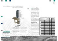
pressure relief valves<br />
In diesem Katalog sind Angaben zur<br />
Ausführung und Anwendung unseres<br />
Druckbegrenzungsventils <strong>DBV40</strong> enthalten.<br />
Die mit den Ventilen ausgelieferte<br />
Betriebsanleitung enthält weitere Hinweise<br />
und ist in jedem Fall zusätzlich zu<br />
beachten.<br />
Änderungen sind vorbehalten.<br />
<strong>DBV40</strong><br />
This section of the catalogue contains<br />
general information and instructions for<br />
the operation of our pressure relief valve<br />
<strong>DBV40</strong>. Our valves are supplied with<br />
operating instructions which include<br />
important notes, which must be respected<br />
in every case. We reserve all<br />
rights to technical changes.<br />
1
Form 229610-1 (11/07)<br />
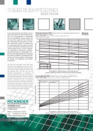
1 Einsatzgebiete<br />
<strong>RICKMEIER</strong> <strong>DBV40</strong>-Druckbegrenzungs<strong>ventile</strong> kommen in der<br />
Ölhydraulik, der Schmiertechnik und bei Verwendung<br />
unterschiedlichster Öle oder schmierfähiger Flüssigkeiten zum<br />
Einsatz. Die Ventile dienen der Druckbegrenzung, sind aber keine<br />
Sicherheits<strong>ventile</strong> im Sinne der DIN 3320.<br />
Typische Industriebereiche<br />
Allgemeiner Maschinenbau, Automobilbau, Apparatebau, Baumaschinen,<br />
Bergwerkstechnik, Chemieanlagenbau, Diesel-<br />
motoren, Druckereimaschinen, Elektromotorenbau, Fahrzeugtechnik,<br />
Gasturbinen, Getriebe, Gießereitechnik, Holzbearbeitungstechnik,<br />
Industriegetriebebau, Kältetechnik, Kompressorenbau,<br />
Kraftwerkstechnik, Motorenbau, Papiermaschinen, Pumpenbau,<br />
Schiffbau, Textilmaschinen, Verdichterbau, Wasserturbinen,<br />
Walzwerkindustrie, Werkzeugmaschinen, Windenergieerzeugung,<br />
Zementanlagenbau.<br />
2 Durchflussmedien<br />
Getriebeöl, Hydrauliköl, Motorenöl.<br />
Andere Medien auf Anfrage.<br />
Als Voraussetzung für lange Lebensdauer und höchste<br />
Betriebssicherheit soll das Durchflussmedium schmierfähig und<br />
nach Möglichkeit sauber und nicht korrosiv, in jedem Fall aber frei<br />
von harten Beimengungen sein. Zusätzlich gelten folgende<br />
Bereiche:<br />
Eigenschaft<br />
Kinematische Viskosität<br />
Verschmutzungsgrad<br />
Gasgehalt (ungelöst)<br />
Temperatur (NBR Dichtungen)<br />
Temperatur (FPM Dichtungen)<br />
characteristics<br />
kinematic viscosity<br />
degree of contamination<br />
gas content (undissolved)<br />
temperature (NBR seals)<br />
temperature (FPM seals)<br />
1) ungelöstes Gas im Durchflussmedium kann zu Druckschwingungen und<br />
erhöhter Schallemission führen.<br />
2) Bei Einsatz über 80°C sind besondere Maßnahmen erforderlich.<br />
Bitte sprechen Sie mit unseren Mitarbeitern.<br />
3 Kenngrößen<br />
Die angegebenen Kenngrößen und unter Abschnitt 2 genannten<br />
Durchflussmedien gelten für Ventile in der Standardausführung.<br />
Sind Überschreitungen der angegebenen Grenzen erforderlich,<br />
sprechen Sie bitte mit unseren Mitarbeitern.<br />
Nenngröße : DN40<br />
Max. Durchfluss : 400 dm³/min<br />
Auslegungsdruck : 100 bar<br />
2<br />
Allgemeine Kenngrößen<br />
Bauart : Sitzventil, hydraulisch vorgesteuert<br />
Befestigungsart : in der Rohrleitung<br />
Leitungsanschluss : metrischer SAE1.1/2-Flansch<br />
Gewicht : 8,5 kg<br />
Einbaulage : beliebig<br />
Hydraulische Kenngrößen<br />
Ansprechdruckbereich : 2...40 bar<br />
p-Q-Kennlinie : siehe Abschnitt 6: “Kennfeld”<br />
Betätigungsart<br />
Mechanisch : Stellspindel<br />
Erhältliches Zubehör : metrische SAE-Flansche<br />
verschiedenster Ausführungen<br />
auf Anfrage<br />
1 Applications<br />
<strong>RICKMEIER</strong> <strong>DBV40</strong>-pressure relief valves are used in the field of<br />
oil hydraulics, lubrication technology and with many of different<br />
oils or lubricants.This valves are for pressure relief purposes.They<br />
are not safety valves according to DIN 3320.<br />
Typical industrial fields:<br />
General machine building, automobile industry, apparatus<br />
engineering, construction machines, mining industry, chemical<br />
industry, diesel engines, printing machines, electric motor<br />
construction, automotive engineering, gas turbines, gears,<br />
industrial gear transmissions, refrigeration technology,<br />
compressor manufacturing, power generation, motor<br />
construction, paper machines, pump industry, shipbuilding, textile<br />
machines, compressor manufacturing, water turbines, rolling<br />
mills, tooling machines, wind energy generation, and cement<br />
plant.<br />
2 Flow media<br />
Gear lubricant oil, hydraulic fluid, crankcase oil.<br />
Other fluids on request.<br />
The flow medium used should have good lubricity to ensure long<br />
life and max. operational safety. If possible, the medium should be<br />
clean and non-corrosive, but always free from undesirable hard<br />
constituents.The following should also be considered:<br />
Einheit unit<br />
2<br />
mm /s<br />
ISO 4406<br />
Vol.-%<br />
°C<br />
°C<br />
min.<br />
7<br />
-<br />
-<br />
-25<br />
-25<br />
max.<br />
15000<br />
21/19/17<br />
1)<br />
10<br />
80<br />
2)<br />
160<br />
1) undissolved gas in the flow medium may cause pressure pulsations and<br />
higher noise emissions.<br />
2) the use above 80°C require particular measures.<br />
Please contact us.<br />
3 Parameters<br />
The parameters shown herein and the flow media presented in<br />
section 2 apply to standard valves. Please contact us, whenever<br />
the specified limits need to be exceeded.<br />
nominal size : DN40<br />
max. flow : 400 dm³/min<br />
design pressure : 100 bar<br />
General parameters<br />
type : globe valve, hydraulically<br />
precontrolled<br />
fixing mode : installation in the pipe<br />
pipe connection : metric SAE1.1/2-flange<br />
weight : 8,5 kg<br />
installation position : any<br />
Hydraulic parameters<br />
set pressure range : 2...40 bar<br />
p-Q-diagram : p.r.t. section 6: “Characteristic”<br />
Actuation mode<br />
mechanical : regulating spindle<br />
available attachments : metric SAE-flange<br />
various variations on request
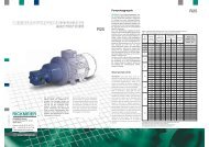
4 Produktbeschreibung und Funktionsweise<br />
<strong>RICKMEIER</strong> <strong>DBV40</strong>-Druckbegrenzungs<strong>ventile</strong> sind hydraulisch<br />
vorgesteuerte Ventile mit metrischem SAE-Anschlussbild. Die<br />
Ventile bestehen im wesentlichen aus dem Hauptventil (Gehäuse<br />
(1), Kolben (3), Blende (4) und Druckfeder (5)) und der angebautenVorsteuereinheit<br />
(2, 12-26), siehe Abb. 1.<br />
Bei geschlossenem Vorsteuerventilsitz dichtet die Kugel (16) die<br />
Bohrung in der Scheibe (15) ab. Die Steuerölblende im Kolben<br />
bewirkt einen Druckausgleich zwischen Ventileintritt und Federraum.<br />
Aufgrund der Durchmesserdifferenz, der Führungsdurchmesser<br />
ist größer als der Sitzdurchmesser, wird der Kolben<br />
zusätzlich zur Federrückstellkraft hydraulisch zugehalten.<br />
Bei Erreichen des eingestellten Öffnungsdruckes hebt die Kugel<br />
vom Ventilsitz ab und es fließt Steueröl intern zum Tank ab. Durch<br />
das sich einstellende Druckgefälle am Kolben öffnet dieser und<br />
der Systemdruck stellt sich ein bzw. wird konstant gehalten. Mit<br />
Hilfe der Stellspindel der Vorsteuereinheit wird der Systemdruck<br />
eingestellt.<br />
Druckerhöhung = Spindel-Rechtsdrehung.<br />
Druckabsenkung = Spindel-Linksdrehung.<br />
Das Steueröl fließt standardmäßig intern zum Tankanschluss.<br />
Druckschwankungen in der Tankleitung beeinflussen den eingestellten<br />
Öffnungsdruck des Ventils. Sind diese Auswirkungen nicht<br />
erwünscht, so ist es möglich das Steueröl über eine externe<br />
Leitung zum Tank abfließen zu lassen. Das Gehäuse wird dann<br />
mit einem entsprechenden Anschluss „Y“ (Einschraubloch DIN<br />
3852-X-G3/8) versehen. Lage des Anschlusses „Y“ siehe Abb. 2,<br />
auch für die später dargestellten Varianten erhältlich.<br />
Der Abschluss „X“ kann nach Entfernen der Verschlussschraube<br />
(8) zur externen Steuerölregelung z. B. zur hydraulischen Entlastung<br />
verwendet werden.<br />
13 24 18 26 12 14 17 22 15 16 20<br />
25 21 19 23 10<br />
P<br />
Abb. 1: Schnittbild Fig. 1: sectional drawing<br />
2<br />
4 Product description and function mode<br />
<strong>RICKMEIER</strong> <strong>DBV40</strong>-pressure relief valves are hydraulically precontrolled<br />
valves with metric SAE connections. Generally the<br />
valves consist of main valve body (1), piston (3), orifice (4) and<br />
compression spring (5) with the attached pilot unit (2, 12-26), p.r.t.<br />
fig. 1.<br />
The ball (20) seals the bore in the washer (15). The orifice in the<br />
piston allows a small oil flow to balance the pressure between<br />
valve inlet and spring chamber. The diameter difference between<br />
piston guide and valve seat produces a hydraulic force. This force<br />
supports the spring in closing the piston.<br />
When the adjusted set pressure is reached the ball lifts off from the<br />
valve seat and control oil flows back internally to the tank. The<br />
piston opens due to the upcoming pressure loss and the required<br />
system pressure is balanced. The required system pressure is<br />
adjusted by the regulating spindle.<br />
pressure increase = spindle clockwise rotation<br />
pressure reduction = spindle counter-clockwise rotation<br />
As a rule the control oil flows internally back to the tank connection.<br />
Pressure pulsations in the pipes leading to the tank can effect the<br />
set pressure. To avoid those reactions it is possible to lead the<br />
control oil back via external pipes: in this case the body can be<br />
equipped with a “Y” connection (bore DIN 3852-X-G3/8). The<br />
position of the “Y” connection is shown in fig. 2.This feature is also<br />
available for the below mentioned valve variants.<br />
After removing the screw plug (8) the “X” connection can be used<br />
for external control oil regulation e.g. for hydraulic release<br />
purposes.<br />
X(G¼)<br />
T<br />
6<br />
7<br />
11<br />
8<br />
9<br />
5<br />
3<br />
1<br />
4<br />
T<br />
P<br />
X<br />
Pos. Benennung / designation<br />
1 Gehäuse / body<br />
2 Deckel / cover<br />
3 Kolben / piston<br />
4 Blende / orifice<br />
5 Druckfeder / compression spring<br />
6 Zylinderschraube / cap screw<br />
7 Scheibe / washer<br />
8 Verschlussschraube / screw plug<br />
9 Dichtring / sealing ring<br />
10 O-Ring / o-ring<br />
11 O-Ring / o-ring<br />
12 Mutter / nut<br />
13 Spindel / spindle<br />
14 Federteller / spring washer<br />
15 Scheibe / washer<br />
16 Kugel / ball<br />
17 Druckfeder / compression spring<br />
18 Sechskantmutter / hexagonal nut<br />
19 Nadelrolle / needle roller<br />
20 Scheibe / washer<br />
21 O-Ring / o-ring<br />
22 O-Ring / o-ring<br />
23 O-Ring / o-ring<br />
24 Hutmutter / cap nut<br />
25 Sprengring / snap ring<br />
26 Dichtring / sealing ring<br />
Symol nach DIN 1219-1<br />
symol acc. to DIN 1219-1<br />
3
Form 229610-1 (11/07)<br />
5 Abmessungen<br />
M12-18<br />
93<br />
69,9<br />
Ø38<br />
Abb. 2: Maßbild<br />
80<br />
35,7<br />
76<br />
Anschluss X(G¼)<br />
connection X(G¼)<br />
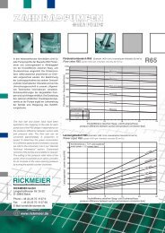
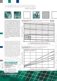
6 Kennfeld<br />
Die dargestellten Kennfelder gelten für das Standard-Druckbegrenzungsventil<br />
mit internem Steuerölablauf und einer kine-<br />
2<br />
matischeViskosität des Mediums von 100 mm /s.<br />
Der Ablaufdruck am Ventilaustritt ist 0 bar (1 bar absolut). Die<br />
Kennlinien können auch für geringere und höhere kinematische<br />
Viskosität verwendet werden. Dabei ändert sich der Druckanstieg<br />
2 2<br />
im Bereich von 10 mm /s bis 2000 mm /s um ± 5% gegenüber den<br />
Werten der Diagramme (geringere Viskosität: kleinerer Druckanstieg).<br />
4<br />
Druck pressure [bar]<br />
50<br />
45<br />
40<br />
35<br />
30<br />
25<br />
20<br />
15<br />
10<br />
5<br />
Ansprechdruck / set pressure<br />
40 bar<br />
25 bar<br />
16 bar<br />
10 bar<br />
4 bar<br />
-6<br />
5 Dimensions<br />
Fig. 2: dimensional drawing<br />
6 Characteristics<br />
The diagrams shown apply to the standard pressure relief valve<br />
with internal control oil drainage (kinematic viscosity of fluid 100<br />
2<br />
mm /s).<br />
The outlet pressure at valve exit is 0 bar (1 bar absolute). The<br />
curves are also valid for the higher or lower kinematic viscosities.<br />
2 2<br />
In the range of 10 mm /s to 2000 mm /s the valve pressure<br />
increase changes in the range of ± 5% compared to diagram<br />
curves (less viscosity: less pressure increase).<br />
0<br />
0 50 100 150 200 250 300 350 400<br />
Durchfluss flow [dm³/min]<br />
Abb. 3: Kennfeld Fig. 3: valve characteristic<br />
191<br />
115<br />
P<br />
Option: externer Steuerölablauf Y(G1/8)<br />
option: drainage of control oil Y(G1/8)<br />
60<br />
10<br />
60<br />
(155)<br />
(175)<br />
(195)<br />
T
7 Bezeichnungen, Typenschlüssel<br />
Die Bezeichnung der <strong>RICKMEIER</strong> <strong>DBV40</strong>-Druckbegrenzungs<strong>ventile</strong><br />
erfolgt nach folgendem Schlüssel:<br />
<strong>DBV40</strong><br />
<strong>DBV40</strong>(25)<br />
1<br />
-<br />
-<br />
B<br />
R<br />
S<br />
2<br />
-<br />
-<br />
-<br />
1 Typ<br />
<strong>DBV40</strong> Kolben DN60<br />
<strong>DBV40</strong>(25) Cartridge-Kolben DN25<br />
2 Funktion<br />
B Druckbegrenzungsventil<br />
R Druckregelventil<br />
S Druckstufenschaltventil<br />
3 Ansprechdruck<br />
Pxx Max. Ansprechdruck in bar<br />
Pxx/xx<br />
(xx)<br />
4 Anschlussart<br />
Pxx<br />
Pxx(xx)<br />
Pxx/xx(xx)<br />
3<br />
Max. Ansprechdruck in bar bei dem Druckschaltventil<br />
Angabe: 1. Druckstufe/2. Druckstufe<br />
Ansprechdruck der fest eingestellten<br />
Überdruckabsicherung in bar (12 oder 40 bar)<br />
SAE Metrisches SAE1.1/2-Anschlussbild<br />
FL Flanschausführung<br />
5 Vorsteuerung (Sitz, Zufuhr, Abfuhr)<br />
B Kugelsitz<br />
C Kegelsitz<br />
P Schieber-Kolben<br />
I Interne Steuerölzufuhr bzw. -abfuhr<br />
E Externe Steuerölzufuhr bzw. -abfuhr<br />
6 Betätigungsart (nur bei Druckstufenschaltventil)<br />
M Elektrisch (Magnet)<br />
D Pneumatisch (Druckluft)<br />
P Proportional<br />
7 Werkstoffe (Gehäuse, Druckfeder, Abdichtung)<br />
S GJS-Späroguss<br />
C C-Stahl<br />
X CrNi-Stahl<br />
N NBR - Acrylnitril-Butadien-Kautschuk<br />
F FPM - Fluor-Kautschuk<br />
E EPDM - Ethylen-Propylen-Dien-Kautschuk<br />
8 Sonderausführung<br />
SO Kennzeichen für nicht geschlüsselte Merkmale<br />
Beispiel:<br />
<strong>DBV40</strong>-R-P8(12)-FL-PII-SXF<br />
<strong>DBV40</strong> mit Kolben DN60, R- Druckregelventil, P8(12)- max. Ansprechdruck<br />
8 bar; Ansprechdruck der fest eingestellten Überdruckabsicherung<br />
12 bar, FL- Flanschausführung (rohrleitungsfreier<br />
Anbau), PII- Schieberkolben-Vorsteuereinheit, interne<br />
Steuerölzufuhr, interne Steuerölabfuhr, SXF- Gehäusewerkstoff<br />
EN-GJS-400-15, Druckfederwerkstoff CrNi-Stahl, F- Abdichtung<br />
FPM .<br />
-<br />
-<br />
SAE<br />
FL<br />
4<br />
7 Identification, type code<br />
<strong>RICKMEIER</strong> <strong>DBV40</strong>-pressure relief valves are identified by the<br />
following code:<br />
-<br />
BII<br />
CEE -<br />
M<br />
D -<br />
LCN<br />
SXF -<br />
P<br />
P<br />
E<br />
5<br />
6<br />
7<br />
1 type<br />
<strong>DBV40</strong> piston DN60<br />
<strong>DBV40</strong>(25) cartridge-piston DN25<br />
2 function<br />
B pressure relief valve<br />
R pressure control valve<br />
S pressure stage control valve<br />
3 set pressure<br />
Pxx max. set pressure in bar<br />
Pxx/xx<br />
SO<br />
max. set pressure in bar for a pressure stage control<br />
valve, assignment: 1. stage/2. stage<br />
set pressure of the fix adjusted overload<br />
(xx)<br />
safety valve in bar (12 or 40 bar)<br />
4 connection<br />
SAE metric SAE1.1/2-connection<br />
FL flange type<br />
5 pilot unit (seat, supply, drain)<br />
B ball seat<br />
C conical seat<br />
P sliding piston<br />
I internal control of oil supply and drainage<br />
E external control of oil supply and drainage<br />
6 fixing mode (only with pressure stage control valve)<br />
M electric (magnet)<br />
D pneumatic (compressed air)<br />
P proportional<br />
7 materials (body, compression spring, sealing)<br />
S GJS - cast with spheriodal graphite<br />
C carbon steel<br />
X CrNi-steel<br />
N NBR - acrylnitril-butadien-rubber<br />
F FPM - fluor-rubber<br />
E EPDM - ethylen-propylene-dien-rubber<br />
8 customized version<br />
SO identification for uncoded features<br />
Example:<br />
<strong>DBV40</strong>-R-P8(12)-FL-PII-SXF<br />
<strong>DBV40</strong> with piston DN60, R- pressure control valve, P8(12)- max.<br />
set pressure 8 bar; set pressure of the fix adjusted overload safety<br />
valve 12 bar, FL- flange type (pipeless attachment), PII- sliding<br />
piston pilot unit, internal control oil supply, internal control oil<br />
drainage, SXF- body material EN-GJS-400-15, spring material<br />
CrNi-Stahl, F- sealing FPM.<br />
8<br />
5
Form 229610-1 (11/07)<br />
6<br />
8 Standardausführung und Varianten<br />
Gehäuseausf.<br />
Hauptkolben<br />
Vorsteuereinheit<br />
Ansteuerung<br />
Steuerölablauf<br />
Steuerölzulauf<br />
Wegeventil<br />
9 Werkstoffe<br />
Gehäuse<br />
Kolben<br />
Druckfeder-Kolben<br />
DF-Vorsteuereinheit<br />
Rund-Dichtringe<br />
* früher gebräuchliche Bezeichnungen<br />
** nur bei den Varianten erhältlich<br />
10 Varianten<br />
Standard Varianten<br />
Rohrleitung (Eckventil) Flansch (Quaderform)<br />
DN60 Cartridge DN25<br />
Kugel (Sitz) Kolben (Patr.-Schieber)<br />
Druckfeder<br />
Kegel (Patr.-Sitz)<br />
Tellerfeder<br />
intern extern<br />
intern<br />
extern<br />
intern<br />
extern<br />
elektrisch<br />
pneumatisch<br />
proportional<br />
Standard<br />
EN-GJS-400-15<br />
(GGG-40)*<br />
Einsatzstahl<br />
C-Stahl<br />
C-Stahl<br />
NBR<br />
alternativ<br />
-<br />
-<br />
-<br />
CrNi-Stahl**<br />
FPM<br />
Abb. 4: Druckbegrenzungsventil mit Schieberkolben-<br />
Vorsteuereinheit<br />
Anwendung : Bei ständiger Durchströmung<br />
des Ventils.<br />
Ansprechdruckbereiche : 2...8 bar, 6...12 bar und 10...40 bar.<br />
Abb. 5: Druckregelventil mit externer Ansteuerung am Anschl. Z<br />
Anwendung : Regelung eines Systemdrucks<br />
unabhängig von den Druckverlusten<br />
zwischen dem Ventil und der<br />
Stelle des externen Steuerölabgriffs.<br />
Ansprechdruckbereiche : 2...8 bar, 6...12 bar und 10...40 bar.<br />
8 Standard version and variations<br />
body type<br />
main piston<br />
pilot unit<br />
(pilot valve)<br />
9 Materials<br />
* previously used descriptions<br />
** only available with variations<br />
10 Variations<br />
X (G¼)<br />
fest eingestellte Überdruckabsicherung<br />
(12 oder 40 bar)<br />
fixed non-adjustable overload<br />
safety valve (12 or 40 bar)<br />
Fig. 4: Pressure relief valve with piston pilot unit<br />
Application : for continuous pressure<br />
regulation.<br />
Set pressure range : 2...8 bar, 6...12 bar and 10...40 bar.<br />
Z (G¼)<br />
X (G¼)<br />
standard variations<br />
pipe inst. (angle valve) flange (cuboidal)<br />
DN60 cartridge DN25<br />
ball (seat) sliding piston pilot unit<br />
compression spring<br />
fest eingestellte Überdruckabsicherung<br />
(12 bar)<br />
fixed non-adjustable overload<br />
safety valve (12 bar)<br />
cone seat pilot unit<br />
disc spring<br />
excitation internal external<br />
control oil drainage internal<br />
external<br />
control oil supply internal<br />
external<br />
directional electric<br />
pneumatic<br />
control valve<br />
proportional<br />
standard<br />
body<br />
EN-GJS-400-15<br />
(GGG-40)*<br />
piston<br />
hardened steel<br />
comp.-spring piston carbon steel<br />
comp.-spring pilot unit carbon steel<br />
o-ring<br />
NBR<br />
alternative<br />
-<br />
-<br />
-<br />
CrNi-steel**<br />
FPM<br />
Fig. 5: Pressure control valve with external control at connection Z<br />
Application : system pressure control<br />
independent of pressure losses<br />
between valve and position of<br />
control oil tapping.<br />
Set pressure range : 2...8 bar, 6...12 bar and 10...40 bar.<br />
T<br />
P<br />
X<br />
Symol nach DIN 1219-1<br />
symol acc. to DIN 1219-1<br />
T<br />
P<br />
X Z<br />
Symol nach DIN 1219-1<br />
symol acc. to DIN 1219-1
Abb. 6: <strong>DBV40</strong>(25)-Druckventil mit Schieberkolben-Vorsteuereinheit<br />
in Flanschausführung für rohrleitungsfreien Anbau.<br />
Anwendung : Bei ständiger Durchströmung<br />
desVentils zur Druckbegrenzung<br />
oder zur Druckregelung.<br />
Ansprechdruckbereiche : 2...8 bar, 6...12 bar und 10...40 bar.<br />
Maße auf Anfrage.<br />
Wegeventil - elektrische (24V DC)<br />
oder pneumatische Betätigung<br />
directional control valve - electrically<br />
(24V DC) or pneumatically operated<br />
Abb. 7: Druckstufenschaltventil<br />
Anwendung: Das Ventil mit metrischem SAE-Anschlussbild wird<br />
z. B. zur Begrenzung des Vorschaltdruckes pKV und des Schaltöldruckes<br />
pK einer Lamellenkupplung in einem Schiffsgetriebe<br />
eingesetzt.<br />
Schaltverlauf siehe Abb. 8.<br />
Ansprechdruckbereiche:<br />
Schaltöldruck pK (1.Stufe) : 10... 40 bar<br />
Vorschaltdruck pKV (2.Stufe) : 2... 20 bar<br />
Maße auf Anfrage.<br />
Cartridge-Kolben DN25<br />
cartridge-piston DN25<br />
P T<br />
Fig. 6: <strong>DBV40</strong>(25)-pressure control valve with piston pilot unit for<br />
pipeless attachment.<br />
Application : for continuous pressure<br />
regulation.<br />
Set pressure range : 2...8 bar, 6...12 bar and 10...40 bar.<br />
Dimensions on request.<br />
P<br />
Schieberkolben-Vorsteuereinheit<br />
Einstellung: 1. Druckstufe pK<br />
sliding piston pilot unit<br />
adjustment: 1. pressure stage pK<br />
Kegelsitz-Vorsteuereinheit<br />
Einstellung: 2. Druckstufe pKV<br />
cone seat pilot unit<br />
adjustment: 2. pressure stage pKV<br />
Hauptventil (Gehäuse, Kolben, Blende, Druckfeder)<br />
main valve (body, piston, orifice, compression spring)<br />
Fig. 7: pressure stage control valve<br />
Application: This type of valve is for instance used to limit the pilot<br />
pressure pKV and control pressure pK at a multidisc clutch for a<br />
marine gear box.<br />
Pressure-time-diagram p.r.t. fig. 8.<br />
Set pressure range:<br />
control pressure pK (1.stage) : 10... 40 bar<br />
pilot pressure pKV (2.stage) : 2...20 bar<br />
Dimensions on request.<br />
Y<br />
T<br />
Symol nach DIN 1219-1<br />
symol acc. to DIN 1219-1<br />
7
Abb. 8: Druck-Zeit-Diagramm<br />
Einschaltvorgang einer Lamellenkupplung.<br />
Abb. 9: Druckstufenschaltventil in Flanschausführung mit<br />
rohrleitungsfreiem Anbau. Maße auf Anfrage.<br />
11 Wartung<br />
<strong>RICKMEIER</strong> Druckbegrenzungs<strong>ventile</strong> sind in der Regel wartungsfrei,<br />
wenn sie innerhalb der zulässigen Einsatzgrenzen betrieben<br />
werden (siehe 3 “Kenngrößen”). Wird ein Druckbegrenzungsventil<br />
infolge von Verschleiß unbrauchbar, so muss es ersetzt<br />
werden. Der Einbau von Ersatzteilen führt nicht wieder zur<br />
ursprünglichen Betriebssicherheit.<br />
8<br />
Druck pressure<br />
pK<br />
pKV<br />
Fülldruck<br />
filling pressure<br />
stromlos<br />
no current<br />
Ventil<br />
valve<br />
Kupplung ein<br />
clutch engaged<br />
Magnet erregt<br />
magnet activated<br />
Kupplung<br />
clutch<br />
Umschaltung pKV-pK<br />
switch over pKV-pK<br />
Fig. 8: pressure-time-diagram<br />
Startup-process of a multidisc clutch.<br />
stromlos<br />
no current<br />
Zeit time<br />
Fig. 9: flange type pressure stage control valve for pipeless<br />
attachment. Dimensions on request.<br />
11 Maintenance<br />
<strong>RICKMEIER</strong> pressure relief valves, as a rule, are maintenancefree,<br />
always provided they are operated within the permissible<br />
limitations (p.r.t. 3 “Parameters”). Any pressure relief valve that<br />
becomes unserviceable due to wear must be replaced. The<br />
installation of spare parts is insufficient to guarantee the original<br />
operational safety.