Typ - F.U.R. Wickeltechnologie GmbH
Typ - F.U.R. Wickeltechnologie GmbH
Typ - F.U.R. Wickeltechnologie GmbH

Sie wollen auch ein ePaper? Erhöhen Sie die Reichweite Ihrer Titel.
YUMPU macht aus Druck-PDFs automatisch weboptimierte ePaper, die Google liebt.
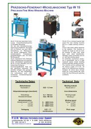
F.U.R. WICKELTECHNOLOGIE GMBH<br />
D GB<br />
Die F.U.R. <strong>Wickeltechnologie</strong> <strong>GmbH</strong>, gegründet am<br />
01.12.2003, ist ein Unternehmen, das sich mit der Entwicklung<br />
und der Produktion von Wickelmaschinen u.a.<br />
für die Elektroindustrie beschäftigt.<br />
Langhansstr. 127-128, D-13086 Berlin<br />
Alle Rechte des Know-Hows der ehemaligen internationalen<br />
Unternehmen "Ramm", "Kandulla" und "Froitzheim<br />
und Rudert" werden bei uns exklusiv vermarktet<br />
Wir haben somit auch ausschließlich die Berechtigung,<br />
diese Programme fortzuführen und Ersatzteile für die<br />
jeweiligen Produkte zu liefern.<br />
Durch die Innovation traditioneller Produkte wird somit<br />
eine noch stärkere Präsenz auf dem Weltmarkt erreicht.<br />
Die Kompetenz und Erfahrung in unserer Branche<br />
drückt sich durch die Vielzahl von Patenten aus, die<br />
auch heute noch zukunftsorientiert sind. Diese Patente<br />
dienen unserem jungen, ingenieur-technischen Team<br />
als innovative Grundlage der Entwicklung neuer und<br />
der Weiterentwicklung bestehender Produkte.<br />
Unsere kundenorientierte Firmenpolitik beweist durch<br />
positive Erfolgsquoten, dass unser Unternehmen, das<br />
internationale Niveau entscheidend mitbestimmt.<br />
Wir bieten Ihnen gerne unsere Unterstützung bei der<br />
Lösung Ihrer Produktions- und Entwicklungsprojekte an.<br />
Produktinnovation, Qualität, Flexibilität und Liefertreue<br />
sind die Eckpfeiler unseres Erfolges.<br />
Wir sind in der Lage, sämtliche Wickelmaschinen der<br />
Elektroindustrie entsprechend Ihren Mustern anzufertigen<br />
und zu liefern.<br />
Wir würden uns freuen, wenn Sie uns Ihr Vertrauen entgegen<br />
bringen würden.<br />
2<br />
The F.U.R. <strong>Wickeltechnologie</strong> <strong>GmbH</strong>, founded on<br />
December 1, 2003 , is a company that occupies<br />
itself with the development and manufacture of winding<br />
machines, among other for the electrical industry.<br />
All rights regarding the „know how“ of the former<br />
international organisations: "Ramm", "Kandulla" and<br />
"Froitzheim und Rudert" are exclusively marketet by<br />
us.<br />
Therefore we also possess the exclusive rights to<br />
continue these programs and to deliver spare parts for<br />
these products.<br />
Through innovation of traditional products we reached<br />
hereby an even stronger presence on the<br />
world market. The competence and experience in<br />
our field is expressed by the multitude of patents<br />
which are future oriented even by today's standards.<br />
These patents are the innovative basis for our young<br />
technical engineering team to develop new products<br />
and improve existing ones.<br />
Our customer-driven company policy prooves by its<br />
high success rates that our firm influences decisively<br />
the international level.<br />
We would be pleased to offer you our support in solving<br />
your production and development project´s needs.<br />
We are able to construct and supply – in accordance<br />
to your samples – every winding machine type of the<br />
electronics industry.<br />
We would be happy if you would give us your confidence<br />
in the future.
R E F E R E N Z E N<br />
Deutschland / Germany<br />
AEG Kondensatoren und Wandler <strong>GmbH</strong>, Berlin<br />
Bühler, Nürnberg<br />
ERGE-Elektrowärme <strong>GmbH</strong>, Schnaittach<br />
Freek, Menden (KSK Gerätetechnik)<br />
Gebrüder Bach <strong>GmbH</strong>, Tambach-Dietharz<br />
Kaschke, Göttingen<br />
Keller Ihne & Tesch<br />
Koch Präzisionsteile <strong>GmbH</strong><br />
Memmert <strong>GmbH</strong>, Büchenbach<br />
MWB, Bamberg<br />
PAMO Reparaturwerk <strong>GmbH</strong>, Bitterfeld<br />
Parzsch Elektromotoren, Döbeln<br />
Preussler, Berlin<br />
Schnellflechter <strong>GmbH</strong>, Berlin<br />
Siemens, Berlin<br />
Siemens, Erfurt<br />
Internationale<br />
MBW Co., Ltd.“ Shanghai<br />
Delta-T Australien<br />
Balteau, Beyne-Heusay, incl. Tochtergesellschaften Belgien<br />
Thiele Brasilien<br />
Baoding Tianwei Group Co., Ltd., China, Hebei Province<br />
Danotherm Elektric A/S Dänemark<br />
Societé TCT Frankreich<br />
Marconi, Monza Italien<br />
Magrini, Savona Italien<br />
Belotti Italien<br />
Elin Östereich<br />
Voestalpine Stahl <strong>GmbH</strong> Österreich<br />
Efacec Portugal<br />
Pfiffner Messwandler AG Schweiz<br />
Sprecher AG, Oberentfelden & Tochtergesellschaften Schweiz<br />
Haefely incl. Tochtergesellschaften Schweiz, Basel<br />
Weidmann Schweiz, Rapperswil<br />
Jing Gang Singapur<br />
ZPA Slowakei<br />
Fernando Pellicer Spanien<br />
ehemals ABB Südafrika Südafrika<br />
Enpay Türkei<br />
Laing <strong>GmbH</strong> Ungarn<br />
Zoom Products Ltd USA Cincinnati OH<br />
3
INHALTSVERZEICHNIS<br />
Maschinenbezeichnung Musterbeispiel Seite<br />
RINGKERNBEWICKELMASCHINE<br />
TOROIDAL WINDING MACHINE<br />
DBA/MDB ...........................................<br />
........................................... ...............6<br />
4<br />
...............8<br />
DB 150 ........................................... .............10<br />
DB 200 ........................................... .............13<br />
DB1 ...........................................<br />
DB1-SM ...........................................<br />
DB2 ...........................................<br />
DB20 ...........................................<br />
DB30 ...........................................<br />
DB40 ...........................................<br />
REW ...........................................<br />
RWA ...........................................<br />
............12-14<br />
............15<br />
............22<br />
............24<br />
............28<br />
............32<br />
............38<br />
............40
Maschinenbezeichnung Musterbeispiel Seite<br />
ERV/PRV ...........................................<br />
5<br />
............42<br />
SDWH ........................................... ............44<br />
KWS ...........................................<br />
Kombinierte Draht- und Bandwickelanlage<br />
COMBINED TOROIDAL WIRE AND<br />
TAPE WINDING INSTALLATION<br />
DBW 20<br />
DBW 30<br />
DBW 40<br />
...........................................<br />
...........................................<br />
............46<br />
............48<br />
............50
Ringkernbewickelmaschinen<br />
TOROIDAL WINDING MACHINE<br />
Die Ringkernbewickelmaschinen sind universell<br />
einsetzbare Ringbewickel- und Bandagiermaschinen<br />
mit separatem Bedienpult und<br />
Fußpedalen. Sie sind ausschließlich zum<br />
Drahtbewickeln bzw. zum Bandagieren von<br />
Ringkernen, entsprechend der jeweiligen Ausrüstung<br />
ausgelegt. Wegen der Vielzahl ihrer<br />
Wickel- und Bandagierköpfe und des umfangreichen<br />
Sonderzubehörs sind sie für viele Bewicklungsaufgaben<br />
geeignet.<br />
Es gilt dabei der Grundsatz, daß die Ringführungsgröße<br />
in Abhängigkeit vom Außendurchmesser<br />
der Ringkerne stehen, und die<br />
Wickelköpfe in Abhängigkeit vom Draht-∅,<br />
Ringkern-Restloch und Ringkernhöhe ausgewählt<br />
werden.<br />
Das besondere der Ringkernbewickelmaschinen<br />
ist eine SPS mit Eigenintelligenz und Klartextführung<br />
zum Ablegen von Wickelprogrammen.<br />
Dieses ermöglicht dem Bediener<br />
nach einmaliger Programmierung die automatische<br />
Abarbeitung unterschiedlicher Wickel-<br />
bzw. Bandagierprogramme.<br />
Darüber hinaus kann die Wickelgeschwindigkeit,<br />
dank der stufenlosen, elektronischen<br />
Drehzahlregelung, den betrieblichen Arbeitsbedingungen<br />
optimal angepasst werden. Der<br />
Vorschub- und der Kopfantrieb sind als NC-<br />
Achsen gekoppelt.<br />
Der Rollenandruck erfolgt je nach Ausführung<br />
pneumatisch bzw. mechanisch.<br />
Korrosionsgefährdete Teile werden galvanisch<br />
behandelt. Alle Antriebe verfügen über genügend<br />
Reserven um eine höchstmögliche Lebensdauer<br />
auch unter schwersten Einsatzbedingungen<br />
zu erreichen.<br />
6<br />
The toroidal winding machines of the DBseries<br />
are universally applicable wire winding<br />
and taping machines, equipped with<br />
separate control panel and pedal. Their<br />
range of application depends on the equipment<br />
which comprises a variety of wire<br />
winding and taping head as well as a comprehensive<br />
range of special accessories.<br />
The equipment will be chosen with respect<br />
to the interdependence between roller table<br />
and outer diameter of the toroidal core, and<br />
between winding heads and wire diameter,<br />
inner diameter and height of the finished<br />
toroid.<br />
The machines are controlled by a PLC<br />
(Programmable Logic Control), with selflearning<br />
and displaying clear-text, allowing<br />
storage of different winding and taping programmes,<br />
so that winding is carried out<br />
automatically.<br />
Electronic speed control permits infinitely<br />
variable winding speed and perfect adaption<br />
to working conditions. Winding head<br />
drive and pitch are coupled as NC-axles.<br />
Following the particular requirements, the<br />
machine will be equipped either with pneumatically<br />
or mechanically working pressure<br />
rollers.<br />
All parts of our machines are corrosion resistant.<br />
All drives have enough power for a<br />
long working life.
<strong>Typ</strong><br />
DBA<br />
MDB<br />
Miniatur-DB<br />
Die DBA ist für die Bewicklung besonders<br />
kleiner Spulen und entwickelt worden, wobei<br />
die MDB für Miniaturspulen geeignet ist.<br />
Beide Maschinen bestechen durch übersichtliche<br />
Anordnung der Tastaturelemente<br />
und einfachste Bedienung.<br />
Durch die vereinfachte Handhabung sind sie<br />
eine kostengünstige Alternative zur DB 1 mit<br />
SPS.<br />
Winding machine which is especially applicable<br />
for very small wire diameters. The MDB is most<br />
effective for miniature coils.<br />
The machine features its clearly arranged operating<br />
elements and easy handling.<br />
Because of their means of simple handling, they<br />
are a cost-efficient alternative to the DB1 with<br />
PLC.<br />
Technische Daten MDB DBA Technical Data<br />
Wickelmaterial Winding material<br />
Runddraht-∅ in mm 0,04 – 0,12 0,05 – 1,8 Round wire (mm)<br />
Bandagiermaterialbreite in mm max. 25 max. 25 Tape material width (mm)<br />
Körperabmessungen (bewickelt)<br />
Core dimensions<br />
Außendurchmesser in mm max. 25 max. 320 Outer core diameter (mm)<br />
Innendurchmesser in mm min. 2,2 min. 5 Inner core diameter (mm)<br />
Körperhöhe in mm ca. 5 max. 110 Core height (mm)<br />
Wickeldrehzahlen in 1/min 0 – 500 0 – 1200 Winding speed (rpm)<br />
(abhängig vom Wickelkopf) (depending on winding head)<br />
Vorschub in mm/U 0,04 - 20 / 0,04 - 20 Pitch range (mm/rev)<br />
(abhängig von Wickeldrehzahl) (depending on winding speed)<br />
8
Standardausrüstung Standard Equipment<br />
Steuerung Machine control<br />
2 separate Vorwahlzähler mit LED - Anzeige (Füllen/<br />
Wickeln)<br />
2 separate counters with preselection and LED - Display<br />
elektronisch synchronisierte Antriebe electronically synchronized drives<br />
Antrieb Drives<br />
Kopfantrieb Drehstrommotor 0,55 kW Winding drive Three-phase motor 0,55 kW<br />
Vorschub Schrittmotor Pitch drive stepping motor<br />
Allgemeine Angaben General data<br />
• elekt. Anschluss 230 V/ 50 – 60 Hz/ 1 kW • electric connection<br />
• Platzbedarf (L×B×H) 650×800 mm • Space required (l×b×h)<br />
• Gewicht ca. 75 kg • Weight<br />
Sonderzubehör Special Accessories<br />
• Austauschbare Wickelköpfe und Magazine • Exchangeable winding heads and magazines<br />
• Austauschbare Ringführungen • Exchangeable roller tables<br />
Es gilt dabei der Grundsatz, daß die Ringführungsgrößen Roller table size is dependent on outer diameter of the toroid,<br />
in Abhängigkeit vom Außendurchmesser der Ringkerne and the taping heads are dependent on the wire (i.e. diameter,<br />
stehen, und die Wickelköpfe in Abhängigkeit vom Draht material, consistance etc.), toroidal residual hole and height of<br />
(Durchmesser, Material, Festigkeit, u.a.), Ringkern-<br />
Restloch und Ringkernhöhe ausgewählt werden.<br />
toroid.<br />
• Magazinloses Ringbewickeln <strong>Typ</strong> RATIOWI DBP • Patented winding system RATIOWI without magazine<br />
• Bifilarwickeleinrichtung • Equipment for bi-filar winding<br />
• Verstellbare Magazinbremse für alle Zahnkranzwi- • Equipment for flat copper wire and resistance wire with<br />
ckelköpfe<br />
corresponding flexural moment<br />
• Auflagetisch für Handführung • Support plate for manual guidance<br />
• Austauschbare Bandagierköpfe • Exchangeable taping heads and magazines<br />
• Verstellbare Segmenthalter • Adjustable segmental clamps<br />
• Lagenend-, Um- oder Abschaltung bei Segment- • Automatic layer end change-over or shut-of device<br />
haltebetrieb<br />
during segmental clamp operation<br />
• Draht- und Bandlängenmesseinrichtung • Wire or tape length measuring unit<br />
• Draht- und Bandabläufe • Wire and tape dereelers<br />
• Drahtleitvorrichtung <strong>Typ</strong> EXAKT DBP • Patented wire guide unit EXAKT DBP<br />
Weiteres Sonderzubehör auf Anfrage Further accessories on request<br />
9
Ringkernbewickelmaschine<br />
TOROIDAL WINDING MACHINE<br />
<strong>Typ</strong>e: DB-150<br />
Die DB-150 ist eine Ringbewickelmaschine für die<br />
Bewicklung kleinen Ringkernen. Sie ist ausgestattet<br />
mit einem klappbaren Ringkernhalter, der ein<br />
sicheres und schnelles Spannen ermöglicht. Die<br />
Halter sind auf einen anderen Wickelkörpertyp<br />
untereinander schnell verstellbar.<br />
Der Vorschub und der Kopfantrieb sind gekoppelt.<br />
Der Rollendruck erfolgt mechanisch. Magazin ist<br />
auswechselbar.<br />
10<br />
The DB-150 is a toroidal winding machine for the<br />
winding of small toroids. It is equipped with a foldable<br />
core holder that grants a safe and quick installation.<br />
The holders are mounted on another<br />
winding core type and quickly adjustable among<br />
each other.<br />
The pitch and the head drive are linked up. The<br />
reel pressure happens mechanically. The magazine<br />
is exchangeable.<br />
Technische Daten Technical data<br />
Wickelmaterial<br />
Runddraht- Ø<br />
Körperabmessungen<br />
(Je nach Ausführung der Ringführung)<br />
Außendurchmesser<br />
Körperhöhe<br />
Wickeldrehzahlen<br />
(abhängig vom Wickelkopf und Draht- Ø)<br />
0,1mm – 0,8mm<br />
15mm - 80mm<br />
max. 50mm<br />
Winding material<br />
Round wire- Ø<br />
0 – 1500 u/min Winding speed<br />
Vorschub Einstellbar / Adjustable Pitch<br />
Antrieb Drive<br />
Core measurements<br />
(depending on issue toroidal guidance)<br />
Outer diametar<br />
Core heigt<br />
(depending on winding head and wire Ø)<br />
Kopfantrieb Gleichstrommotor 120W DC- engine 120W Head drive<br />
Vorschub 2 Gleichstrommotoren 30W 2 DC engines 30W Pitch<br />
Austauschbare Wickelköpfe und Magazine Exchangeable winding heads and magazines<br />
Weiteres Sonderzubehör auf Anfrage Further accessories on request<br />
Technische Änderungen Vorbehalten Technical data subject to change.
<strong>Typ</strong>e: DB-200<br />
Die DB-200 ist eine Ringbewickelmaschine für die<br />
Bewicklung kleinen Ringkernen. Sie ist ausgestattet<br />
mit einem Ringkernhalter, der ein sicheres und<br />
schnelles Spannen ermöglicht. Die Halter sind auf<br />
einen anderen Wickelkörpertyp untereinander<br />
schnell verstellbar.<br />
Der Vorschub und der Kopfantrieb sind gekoppelt.<br />
Der Rollendruck erfolgt mechanisch. Magazin ist<br />
auswechselbar.<br />
11<br />
The DB-200 is a toroidal winding machine for the<br />
winding of small toroids. It is equipped with a core<br />
holder that grants a safe and quick installation.<br />
The holders are mounted on another winding core<br />
type and quickly adjustable among each other.<br />
The pitch and the head drive are linked up. The<br />
reel pressure happens mechanically. The magazine<br />
is exchangeable.<br />
Technische Daten Technical data<br />
Wickelmaterial<br />
Runddraht- Ø<br />
Körperabmessungen<br />
(Je nach Ausführung der Ringführung)<br />
Restloch<br />
Wickeldrehzahlen<br />
(abhängig vom Wickelkopf und Draht- Ø)<br />
0.4 – 1.32mm<br />
Winding material<br />
Round wire- Ø<br />
Ø 0,8mm bei max. Körperhöhe<br />
20mm<br />
Core measurements<br />
(depending on issue toroidal guidance)<br />
Rest hole<br />
0 – 300 u/min Winding speed<br />
Vorschub Einstellbar / Adjustable Pitch<br />
Austauschbare Wickelköpfe und Magazine Exchangeable winding heads and magazines<br />
Weiteres Sonderzubehör auf Anfrage Further accessories on request<br />
Technische Änderungen Vorbehalten Technical data subject to change.<br />
(depending on winding head and wire Ø)
RINGKERNBEWICKELMASCHINE<br />
TOROIDAL WINDING MACHINE<br />
<strong>Typ</strong> DB 1<br />
Die DB 1 ist eine universell einsetzbare Ringbewickel- und Bandagiermaschine<br />
mit separatem Bedienpult und Fußpedalen. Sie ist ausschließlich<br />
zum Drahtbewickeln bzw. zum Bandagieren von kleinen<br />
Ringkernen, entsprechend der jeweiligen Ausrüstung ausgelegt.<br />
Wegen der Vielzahl ihrer Wickel- und Bandagierköpfe und des umfangreichen<br />
Sonderzubehörs ist sie für viele Bewicklungsaufgaben geeignet.<br />
Darüber hinaus kann die Wickelgeschwindigkeit, dank der stufenlosen,<br />
elektronischen Drehzahlregelung, den betrieblichen Arbeitsbedingungen<br />
optimal angepaßt werden. Der Vorschub- und der Kopfantrieb sind<br />
als NC-Achsen gekoppelt. Der Rollenandruck erfolgt je nach Ausführung<br />
pneumatisch bzw. mechanisch.<br />
Korrosionsgefährdete Teile werden galvanisch behandelt. Alle Antriebe<br />
verfügen über genügend Reserven um eine höchstmögliche Lebensdauer<br />
auch unter schwersten Einsatzbedingungen zu erreichen.<br />
12<br />
Musterbeispiele<br />
DB1 mit Bandkopf<br />
DB1 With taping head<br />
The DB1 is a universally applicable machine for toroidal winding<br />
as well as taping with a separate operations console and<br />
pedals. It is capable of performing a considerable variety of<br />
winding and taping tasks.<br />
Since various winding and taping heads as well as special<br />
accessories are available, its range of application is considerable.<br />
The winding speed is electronically controlled and infinitely<br />
variable, thus allowing perfect adaption to the working conditions.<br />
Drive of pitch and winding head are coupled by NCaxles.<br />
Following the particular requirements, the machine will<br />
be equipped either with pneumatically operated pressure rollers<br />
or with a mechanically working roller table.<br />
All parts of our machines are corrosion resistant. All drives have<br />
enough power for a long working life.<br />
Technische Daten Technical Data<br />
Wickelmaterial Winding material<br />
Runddraht-∅ 0,05 - 1,8 mm Round wire<br />
Bandagiermaterialbreite max. 25 mm Tape material width<br />
Körperabmessungen (bewickelt) Core dimensions<br />
Außendurchmesser max. 320 mm Outer core diameter<br />
Innendurchmesser min. 5 mm Inner core diameter<br />
Körperhöhe max. 110 mm Core height<br />
Wickeldrehzahlen 0 - 1200 1/min Winding speed<br />
(abhängig vom Wickelkopf) (depending on winding head)<br />
Vorschub 0,01-99 mm/U/mm/rev Pitch range<br />
(abhängig von Wickeldrehzahl) (depending on winding speed)
RINGKERNBEWICKELMASCHINE für Starkdraht<br />
TOROIDAL WINDING MACHINE FOR STRONG WIRE<br />
<strong>Typ</strong> DB 1<br />
Text siehe DB1 ! Text See DB1!<br />
Technische Daten Technical Data<br />
Wickelmaterial Winding material<br />
Runddraht-∅ 0,05 – 2,35 mm Round wire<br />
Bandagiermaterialbreite max. 25 mm Tape material width<br />
Körperabmessungen (bewickelt) Core dimensions<br />
Außendurchmesser max. 320 mm Outer core diameter<br />
Innendurchmesser min. 5 mm Inner core diameter<br />
Körperhöhe max. 110 mm Core height<br />
Wickeldrehzahlen 0 - 600 1/min Winding speed<br />
(abhängig vom Wickelkopf) (depending on winding head)<br />
Vorschub 0,01-99 mm/U/mm/rev Pitch range<br />
(abhängig von Wickeldrehzahl) (depending on winding speed)<br />
13
Standardausrüstung Standard Equipment<br />
Steuerung Machine control<br />
• SPS mit Eigenintelligenz und Klartextführung, bis zu • Programmable logic control unit Max. 99 winding<br />
programs<br />
• 99 Wickelprogramme möglich, 2 Achsen NC -<br />
Steuerung<br />
Antrieb Drives<br />
• NC - control in X and Y direction<br />
Kopfantrieb Drehstrommotor 0,55 kW Winding drive Three-phase motor 0,55 kW<br />
Vorschub Schrittmotor Pitch drive stepping motor<br />
Allgemeine Angaben General data<br />
• elekt. Anschluß 220 V/ 50 - 60 Hz/ 1 kW • electric connection<br />
• Druckluft max. 6 bar • Compressed air<br />
• Platzbedarf (L×B×H) 1000×800x620 mm • Space required (l×b×h)<br />
• Gewicht ca. 85 kg • Weight<br />
Sonderzubehör Special Accessories<br />
• Austauschbare Wickelköpfe und Magazine • Exchangeable winding heads and magazines<br />
• Austauschbare Ringführungen • Exchangeable roller tables<br />
Es gilt dabei der Grundsatz, daß die Ringführungsgrößen Roller table size is dependent on outer diameter of the toroid,<br />
in Abhängigkeit vom Außendurchmesser der Ringkerne and the taping heads are dependent on the wire (i.e. diameter,<br />
stehen, und die Wickelköpfe in Abhängigkeit vom Draht material, consistance etc.), toroidal residual hole and height of<br />
(Durchmesser, Material, Festigkeit, u.a.), Ringkern-<br />
Restloch und Ringkernhöhe ausgewählt werden.<br />
toroid.<br />
• Taktbremseinrichtung • Cycle braking device<br />
• Magazinloses Ringbewickeln <strong>Typ</strong> RATIOWI DBP • Patented winding system RATIOWI without magazine<br />
• Bifilarwickeleinrichtung • Equipment for bi-filar winding<br />
• Verstellbare Magazinbremse für alle Zahnkranzwi- • Equipment for flat copper wire and resistance wire with<br />
ckelköpfe<br />
corresponding flexural moment<br />
• Auflagetisch für Handführung • Support plate for manual guidance<br />
• Austauschbare Bandagierköpfe • Exchangeable taping heads and magazines<br />
• Verstellbare Segmenthalter • Adjustable segmental clamps<br />
• Lagenend-, Um- oder Abschaltung bei Segment- • Automatic layer end change-over or shut-of device<br />
haltebetrieb<br />
during segmental clamp operation<br />
• Draht- und Bandlängenmeßeinrichtung • Wire or tape length measuring unit<br />
• Draht- und Bandabläufe • Wire and tape dereelers<br />
• Drahtleitvorrichtung <strong>Typ</strong> EXAKT DBP • Patented wire guide unit EXAKT DBP<br />
Weiteres Sonderzubehör auf Anfrage Further accessories on request<br />
Technische Änderungen vorbehalten<br />
Design subjekt to change,<br />
14
<strong>Typ</strong><br />
DB 1-SM<br />
Die DB 1-SM ist eine Ringbewickelmaschine,<br />
die ausschließlich zum Drahtbewickeln<br />
von besonders kleinen Ringkernen auch<br />
Keramikheizkernen, entsprechend der jeweiligen<br />
Ausrüstung ausgelegt ist. Sie ist ausgestattet<br />
mit einem Segmenthalter auf einem<br />
Präzisionsrundtisch. Bedienpult und Fußschalter<br />
sind separat angebracht.<br />
Der Segmenthalter ist mit einem Schnellspannsystem<br />
versehen. Dieses ermöglicht<br />
ein sicheres, schnelles Spannen der einzelnen<br />
Wickelkörper. Zusätzlich ist der Segmenthalter<br />
auf einen Präzisions-Rundtisch<br />
montiert, der sich durch hohe Genauigkeit<br />
auszeichnet. Die Spannteile bzw. die Halter<br />
sind untereinander schnell umrüstbar, auf<br />
einen anderen Wickelkörpertyp.<br />
Der Vorschub- und der Kopfantrieb sind als<br />
NC-Achsen gekoppelt.<br />
The DB1 is a universally applicable machine for<br />
toroidal winding equipped with a segment holder on<br />
a precision ball table, as well as taping with a separate<br />
operations console and pedals.<br />
It is capable of performing a considerable variety of<br />
winding winding tasks. The segment holder is<br />
equipped with a fast clamping system. This enables<br />
safe and quick clamping of the respective winding<br />
cores. Furthermore, the segment holder is mounted<br />
on a precision ball table with high speed quality.<br />
Also, the winding speed can be adapted to the<br />
working conditions. Drive of pitch and winding head<br />
are coupled by NC-axles.<br />
Technische Daten Technical Data<br />
Wickelmaterial Winding material<br />
Runddraht-∅ 0,035 – 1,8 mm Round wire<br />
Körperabmessungen Core dimensions<br />
Außendurchmesser max. 50 mm Outer core diameter<br />
Innendurchmesser min. 5 mm Inner core diameter<br />
Körperhöhe<br />
(abhängig vom Außen- und Innendurchmesser)<br />
max. 30 mm Core height<br />
(depending on outside and inside diameter)<br />
Wickeldrehzahlen 0 – 300 1/min Winding speed<br />
(abhängig vom Wickelkopf) (depending on winding head)<br />
Vorschub in mm/U -1,999 - +1,999 Pitch range in mm/rev<br />
(abhängig von Wickeldrehzahl) (depending on winding speed)<br />
16
Standardausrüstung Standard Equipment<br />
Steuerung Machine control<br />
• SPS mit Eigenintelligenz und Klartextführung, bis zu • Programmable logic control unit Max. 99 winding programmes<br />
• 99 Wickelprogramme möglich, 2 Achsen NC –<br />
Steuerung<br />
Antrieb Drives<br />
• NC – control in X and Y direction<br />
Kopfantrieb Drehstrombremsmotor 0,25 kW Winding drive Three-phase motor 0,55 kW<br />
Vorschub Schrittmotor Pitch drive stepping motor<br />
• Wickelkopf ∅100 • Winding head ∅100<br />
• Rundtisch • Ball table<br />
Wickelgeschwindigkeit und Ringkernvorschub<br />
sind stufenlos einstellbar<br />
• Segmenthalter • Segment holder<br />
17<br />
Winding speed and ring core pitch can be set<br />
steplessly<br />
Allgemeine Angaben General data<br />
• elekt. Anschluss 230 V/ 50 – 60 Hz/ 1 kW • Electric connection<br />
• Platzbedarf ca. (L x T x H) 610 x 800 x 1200 • Space required (l ×b ×h)<br />
• Gewicht ca. 150 kg • Weight<br />
Sonderzubehör Special Accessories<br />
• Austauschbare Wickelköpfe und Magazine • Exchangeable winding heads and magazines<br />
• Austauschbare Ringführungen • Exchangeable roller tables<br />
Es gilt dabei der Grundsatz, daß die Ringführungsgrößen<br />
in Abhängigkeit vom Außendurchmesser der Ringkerne<br />
stehen, und die Wickelköpfe in Abhängigkeit vom Draht<br />
(Durchmesser, Material, Festigkeit, u.a.), Ringkern-<br />
Restloch und Ringkernhöhe ausgewählt werden.<br />
Roller table size is dependent on outer diameter of the toroid, and<br />
the taping heads are dependent on the wire (i.e. diameter, material,<br />
consistance etc.), toroidal residual hole and height of toroid.<br />
• Austausch- und verstellbare Segmenthalter • Exchangeable, adjustable segmental clamps<br />
• Lagenend-, Um- oder Abschaltung bei Segmenthaltebetrieb<br />
• Taktbremseinrichtung • Cycle braking device<br />
• Automatic layer end change-over or shut-of device during<br />
segmental clamp operation<br />
• Magazinloses Ringbewickeln <strong>Typ</strong> RATIOWI DBP • Patented winding system RATIOWI without magazine<br />
• Bifilarwickeleinrichtung • Equipment for bi-filar winding<br />
• Verstellbare Magazinbremse für alle Zahnkranzwickelköpfe<br />
• Equipment for flat copper wire and resistance wire with<br />
corresponding flexural moment<br />
• Auflagetisch für Handführung • Support plate for manual guidance<br />
• Austauschbare Bandagierköpfe • Exchangeable taping heads and magazines<br />
• Verstellbare Segmenthalter • Adjustable segmental clamps<br />
• Lagenend-, Um- oder Abschaltung bei Segmenthaltebetrieb<br />
• Automatic layer end change-over or shut-of device during<br />
segmental clamp operation<br />
• Draht- und Bandlängenmesseinrichtung • Wire or tape length measuring unit<br />
• Draht- und Bandabläufe • Wire and tape dereelers<br />
• Drahtleitvorrichtung <strong>Typ</strong> EXAKT DBP • Patented wire guide unit EXAKT DBP
DBA/DB1 STANDARD-NORMALMAGAZINE<br />
Magazin Füllraum Restloch bei körperhöhe (in mm) Drahtlänge (in m) - bei Draht-∅ (in mm)<br />
cm 3 10 20 30 40 50 60 70 80 90 100 110 0,1 0,2 0,3 0.4 0,5 0,6 0,7 0,8 1,0 1,2 1,4 1,5 1,6 1,8<br />
WZ 10.12 2,8 12,0 13,5 15,0 17,0 20,0 - - - - - - 188 52 24 14 9 6 4,5 3,5 2,4 1,5 - - - -<br />
WZ 10.15 7,8 15.0 16,5 18,0 20,0 22,5 - - - - - - 456 128 59 34 22 15 11,5 8,5 5,5 4,5 - - - -<br />
WZ 10.20 13,6 20,0 20,5 21,5 23,0 25,5 - - - - - - 912 257 119 68 44 31 23 17,5 11,5 8 6 - - -<br />
WZ 10.25 21,5 25,0 25,0 26,0 27,5 30,0 - - - - - - - 406 189 109 70 49 37 28 18 12,5 9,5 8 - -<br />
WZ 15.14 6,0 14,0 15,0 16.0 17,5 19,5 21,5 24,0 - - - - 403 113 52 30 19 13 10 7,5 5 3,5 - - - -<br />
WZ 15.18 13,8 18,0 18,0 18,5 19,5 21,0 23,0 26,0 - - - - 913 260 121 70 45 31 23,5 18 12 8 - - - -<br />
WZ 15.22 24,9 22,0 23,0 23,5 24,5 26,0 28.0 30,5 - - - - - 470 219 126 82 59 43 32 21 14,5 11 - - -<br />
WZ 15.27 41,2 27,0 28,0 29,0 30,0 31,5 33,5 36,0 - - - - - 778 362 208 135 94 71 54 35 24 18 16 - -<br />
WZ 15.31 59,5 31.0 32,0 33,0 34,5 35,5 37,5 40,0 - - - - - - 523 300 195 137 103 78 51 35 26 23 20 -<br />
WZ 15.36 78,0 36,0 37,0 37,5 38,5 40,0 42,0 44,5 - - - - - - 686 395 255 178 135 102 69 46 35 30 27 -<br />
WZ 20.16 13,8 - 16,5 17,5 18,5 19,5 20,5 22,0 24,0 26,5 29,0 32,0 - 260 121 70 45 31 23,5 18 12 8 - - - -<br />
WZ 20.20 25,8 - 20,0 20,7 21,5 22,5 24,0 25,5 27,5 29,5 32,5 35,5 - 487 227 130 84 59 44 33 22 15 11,5 - - -<br />
WZ 20.25 47,0 - 25,0 25,7 26,5 27,5 28,5 30,0 32,0 34,0 36,5 39,5 - 888 413 238 154 108 81 61 40 28 21 18 - -<br />
WZ 20.30 80,0 - 30,0 30,8 31,5 32,5 33,5 35,0 37,0 39,0 42,0 45,0 - - 704 405 262 184 138 105 69 47 35 31 27,5 -<br />
WZ 20.37 118,0 - 37,0 37,0 37,5 38,5 40,0 41,5 43,5 45,5 48,0 51,0 - - 1039 595 388 270 204 155 102 70 53 46 41 -<br />
WZ 20.47 185,0 - 47,0 47,5 48,0 49,0 50,5 52,0 53,5 55,5 58,0 61,0 - - - 935 608 425 320 242 160 110 83 72 64 51<br />
WZ 20.60 316,0 - 60,0 60,0 60,5 61,5 63,0 64,5 66,5 69,0 72,0 75,0 - - - - 1040 725 545 415 272 188 142 124 109 87<br />
DBA/DB1 STANDARD-RATIOWI-WICKELKÖPFE MIT QUERSPULE<br />
Magazin Füllr. Restloch bei körperhöhe (in mm) Drahtlänge (in m) - bei Draht-∅ (in mm)<br />
cm³ 10 20 30 40 50 60 70 80 90 100 110 0,05 0,08 0,1 0,15 0,2 0,25 0,3 0,4 0,5 0,6 0,7 0,8<br />
WR10.10 I 0,15 10,0 11,0 12,5 14,5 18,0 -- -- -- -- -- -- 35,5 15,6 10,0 4,6 2,83 1,84 -- -- -- -- -- --<br />
WR10.12 I 0,28 12,0 13,0 14,5 16,5 20,0 -- -- -- -- -- -- 66,2 29,1 18,8 8,7 5,29 3,44 -- -- -- -- -- --<br />
WR10.15 I 0,69 15,0 16,0 17,5 20,0 23,0 -- -- -- -- -- -- 163,3 71,8 46,3 21,5 13,0 8,49 -- -- -- -- -- --<br />
WR10.18 I 1,0 18,0 19,0 20,5 23,0 26,5 -- -- -- -- -- -- -- 104,1 67,1 31,2 18,9 12,3 8,80 5,07 -- -- -- --<br />
WR10.20 I 1,68 20,0 21,0 22,5 25,0 28,5 -- -- -- -- -- -- -- 174,9 112,8 52,4 31,7 20,6 14,8 8,52 -- -- -- --<br />
WR10.25 I 3,18 25,0 26,0 27,5 30,0 34,0 -- -- -- -- -- -- -- 331,1 213,6 99,2 60,1 39,1 28,0 16,1 -- -- -- --<br />
WR10.30 I 5,52 30,0 31,0 33,0 36,5 41,0 -- -- -- -- -- -- -- -- 370,8 172,2 104,3 67,9 48,6 28,0 18,1 12,7 -- --<br />
WR10.40 I 13,67 40,0 41,5 44,0 47,5 54,0 -- -- -- -- -- -- -- -- 918,4 426,6 258,4 168,3 120,3 69,3 45,0 31,4 -- --<br />
WR15.18 I 0,96 18,0 18,5 20,0 21,5 23,5 26,0 29,0 -- -- -- -- -- 99,9 64,5 29,9 18,1 11,8 8,45 4,97 3,16 -- -- --<br />
WR15.22 I 1,85 22,0 23,0 24,0 25,0 27,0 29,5 33,0 -- -- -- -- -- 192,6 124,3 57,7 34,9 22,7 16,2 9,38 6,09 -- -- --<br />
WR15.26 3,65 26,0 27,0 28,0 29,5 31,5 34,0 37,0 -- -- -- -- -- 380,0 245,2 113,9 69,0 44,9 32,1 18,5 12,0 -- -- --<br />
WR15.30 I 6,25 30,0 31,0 32,0 34,0 36,0 38,0 42,0 -- -- -- -- -- 650,7 419,9 195,0 118,1 76,9 55,0 31,7 20,5 -- -- --<br />
WR15.36 I 11,45 36,0 36,5 37,5 39,0 41,0 44,0 47,5 -- -- -- -- -- -- 769,2 357,3 216,4 140,9 100,8 58,0 37,7 26,3 19,8 --<br />
WR15.42 I 19,25 42,0 43,0 44,0 45,0 46,5 50,0 54,0 -- -- -- -- -- -- 1293 600,7 363,9 237,0 169,5 97,6 63,4 44,3 33,4 --<br />
WR15.48 I 29,2 48,0 48,5 49,5 51,0 53,0 56,0 60,0 -- -- -- -- -- -- 1962 911,3 552,0 359,5 257,1 148,1 96,1 67,2 50,6 --<br />
WR20.32 I 7,3 32,0 32,0 32,5 33,5 34,5 36,0 37,5 40,0 42,5 45,5 48,5 -- -- 490,4 227,8 138,0 89,8 64,2 37,0 24,0 -- -- --<br />
WR20.36 I 11,4 36,0 36,0 37,0 38,0 39,0 40,5 42,0 44,0 47,0 49,5 53,0 -- -- 765,9 355,8 215,5 140,3 100,3 57,8 37,5 -- -- --<br />
WR20.42 I 19,2 42,0 42,0 43,0 44,0 45,0 46,0 48,0 50,0 53,0 56,0 59,5 -- -- -- -- 362,9 236,3 169,0 57,4 63,2 44,2 -- --<br />
WR20.45 I 23,2 45,0 45,0 46,0 47,0 48,0 49,5 51,5 54,0 56,5 60,0 64,0 -- -- -- -- 438,5 285,6 204,2 117,6 76,4 53,4 40,2 30,5<br />
WR20.48 I 29,2 48,0 48,0 49,0 50,0 51,0 52,5 54,0 56,0 58,5 62,0 66,0 -- -- -- -- 552,0 359,5 257,1 148,1 96,1 67,2 50,6 38,4<br />
WR20.55 I 45,3 55,0 55,0 56,0 57,0 58,0 59,5 61,5 64,0 66,5 70,0 74,0 -- -- -- -- 856,3 557,7 398,8 229,8 149,2 104,3 78,6 59,5<br />
DBA/DB1 STANDARD-RATIOWI-WICKELKÖPFE MIT LÄNGSSPULE<br />
Magazin Füllr. Restloch bei körperhöhe (in mm) Drahtlänge (in m) - bei Draht-∅ (in mm)<br />
cm³ 10 20 30 40 50 60 70 80 90 100 110 0,05 0,08 0,1 0,15 0,2 0,25 0,3 0,4 0,5 0,6 0,7 0,8<br />
WR10.20 II 5,15 20,0 21,5 23,0 25,5 29,0 -- -- -- -- -- -- 1218 536,2 346,0 160,7 97,3 63,4 45,3 26,1 -- -- -- --<br />
WR10.25 II 10,0 25,0 26,0 27,0 30,0 34,0 -- -- -- -- -- -- -- 1041 671,8 312,1 189,0 123,1 88,0 50,7 32,9 -- -- --<br />
WR10.30 II 15,9 30,0 30,0 31,5 34,0 39,0 -- -- -- -- -- -- -- -- 1068 496,7 300,5 195,7 140,0 80,6 52,3 -- -- --<br />
WR10.36 II 21,9 35,0 36,0 37,0 40,0 44,0 -- -- -- -- -- -- -- -- 1471 683,5 413,9 269,6 192,8 111,0 72,1 50,4 -- --<br />
WR10.42 II 31,3 42,0 43,0 44,0 47,0 51,0 -- -- -- -- -- -- -- -- 2102 976,8 591,6 385,3 275,6 158,7 103,1 72,0 -- --<br />
WR15.30 II 18,6 30,0 30,5 31,5 33,0 35,0 37,5 40,5 -- -- -- -- -- 1936 1249 580,5 351,6 229,0 163,7 94,3 61,2 42,8 --<br />
WR15.36 II 32,0 36,0 36,5 37,5 39,0 41,0 43,5 47,0 -- -- -- -- -- -- 2150 998,7 604,9 393,9 281,7 162,3 105,4 73,6 --<br />
WR15.42 II 48,6 42,0 42,5 43,0 45,0 47,5 50,0 54,5 -- -- -- -- -- -- 3265 1516 918,7 598,3 427,9 246,5 160,0 111,9 84,3<br />
WR15.48 II 69,0 48,0 48,5 49,5 51,5 54,0 57,0 61,5 -- -- -- -- -- -- -- 2153 1304 849,5 607,5 350,0 227,2 158,8 119,7<br />
WR20.36 II 36,7 36,0 36,0 36,5 37,5 38,5 39,5 41,0 43,5 46,0 49,0 53,0 -- -- -- 1145 693,7 451,8 323,1 186,1 120,8 84,5 63,7 --<br />
WR20.42 II 53,6 42,0 42,0 42,5 43,0 44,0 45,5 47,5 49,5 52,0 55,5 59,0 -- -- -- 1672 1013 659,9 471,9 271,8 176,5 123,4 93,0 --<br />
WR20.48 II 77,1 48,0 48,0 48,5 49,5 50,5 52,0 53,5 56,0 59,0 62,0 66,0 -- -- -- -- 1457 949,2 678,8 391,1 253,9 177,5 133,8 101,4<br />
WR20.56 II 105,8 56,0 56,0 56,0 56,5 57,0 58,5 60,5 63,0 66,0 69,5 73,5 -- -- -- -- 2000 1302 931,5 536,6 348,4 243,6 183,6 139,1<br />
WR20.64 II 150,9 64,0 64,0 64,0 64,0 64,5 66,0 68,0 71,0 74,5 78,0 83,0 -- -- -- -- 2852 1857 1328 765,4 496,7 347,4 261,9 198,4<br />
18
DBA/DB1 STANDARD-SPREIZMAGAZINE MIT AUSSENGLEITER<br />
Magazin Füllraum Restloch bei körperhöhe (in mm) Drahtlänge (in m) - bei Draht-∅ (in mm)<br />
in cm 3 5 10 15 20 25 30 40 50 60 70 80 0,05 0,1 0,15 0,2 0,25 0,3 0,4 0,5 0,6 0,7<br />
WF 10.04 0,6 4,0 4,5 5,0 5,5 6,0 6,5 8,5 - - - - 125 40 18 11 - - - - - -<br />
WF 10.06 1,35 6,0 6,5 7,0 7,5 8,0 8,5 10,5 - - - - 290 90 42 25 16 11 - - - -<br />
WF 10.08 3,4 8,0 8,5 9,0 9,5 10,0 10,5 12,5 - - - - 735 228 106 64 41 29 17 - - -<br />
WF 10.10 5,5 10.0 10,5 11,0 11,5 12,0 12,5 14,5 - - - - - 368 170 102 67 48 27 18 - -<br />
WF 10.12 9,0 12,0 12,0 12,0 12,5 13,0 13,6 16,0 - - - - - 604 280 170 110 79 45 29 - -<br />
WF 15.06 2,1 6,0 6,5 6,5 7,0 7,5 8,0 8,5 10,5 12,5 - - 450 140 65 39 25 18 - - - -<br />
WF 15.08 5,2 8,0 8,5 8,5 9,0 9,5 10,0 10,5 12,0 14,0 - - 1120 345 162 98 64 45 26 - - -<br />
WF 15.10 9,2 10,0 10,0 10,5 10,5 11,0 11,5 12,0 14,0 16,0 - - - 615 286 172 113 81 46 30 - -<br />
WF 15.12 14.0 12.0 12.0 12.5 12.5 12.5 13,0 14,0 16,0 18,0 - - - 940 435 264 172 123 71 46 - -<br />
WF 15.14 20,2 14,0 14,0 14,5 14,5 14,5 15,0 16,0 18,0 20,5 - - - 1355 630 380 248 177 102 66 46 -<br />
WF 15.16 29,6 16,0 16,0 16,5 16,5 16,5 17,0 18,0 20,0 22,5 - - - 1985 920 558 364 260 150 97 68 38<br />
WF 20.08 7,6 8,0 8,0 8,0 8,5 8,5 9,0 9,5 10,5 12,0 13,5 15,5 - 510 235 142 92 66 38 - - -<br />
WF 20.10 13,0 10,0 10,0 10,0 10,5 10,5 11,0 11,5 12,5 13,5 15,0 17,0 - 890 405 245 160 104 65 42 - -<br />
WF 2012 20,6 12,0 12,0 12,0 12,5 12,5 13,0 13,5 14,5 15,5 17,0 18,5 - 1380 640 388 252 180 104 67 - -<br />
WF 20.14 30,5 14,0 14,0 14,0 14,5 14,5 15,0 15,5 16,5 17,5 19,0 21,0 - 2045 950 575 375 268 154 100 70 -<br />
WF 20.16 44,5 16,0 16,0 16,0 16,5 16,5 17,0 17,5 18,5 19,5 21,0 23,0 - 2985 1380 840 545 390 225 146 102 58<br />
WF 20.18 61,0 18,0 18,0 18,0 18,5 18,5 19,0 19,5 20,5 21,5 23,0 25,0 - - 1900 1150 750 535 309 200 140 80<br />
WF 20.20 75,0 20,0 20,0 20,0 20,5 20,5 21,0 21,5 22,5 23,5 25,0 26,5 - - 2340 1415 922 660 380 245 172 98<br />
DBA/DB1 STANDARD-SPREIZMAGAZINE FÜR BANDANTRIEBSKÖPFE<br />
Magazin Füllraum Restloch bei körperhöhe (in mm) Drahtlänge (in m) - bei Draht-∅ (in mm)<br />
in cm 3 5 10 15 20 25 30 40 50 60 0,3 0,4 0,5 0,6 0,7 0,8 0,9 1,0<br />
WB 10.04 1,0 4,0 4,5 5,0 5,5 6,0 7,0 8,5 - - 8,8 5,0 3,3 2,3 1,7 1,3 - -<br />
WB 10.06 2,4 6,0 6,5 7,0 7,5 8,0 9,0 10,5 - - 21,0 12,0 7,5 5,5 4,0 3,0 - -<br />
WB 10.08 5,2 8,0 8,5 9,0 9,5 10,0 11,0 12,5 - - 45,0 26,0 17,0 11,5 9,0 6,5 - -<br />
WB 10.10 8,5 10,0 10,5 11,0 11,5 12,0 13,0 14,5 - - 74,0 43,0 27,5 19,5 14,5 11,0 - -<br />
WB 15.04 1,7 4,0 4,5 5,0 5,5 6,0 7,0 8,5 11,0 - 14,0 8,5 5,5 3,5 2,5 2,0 1,7 0,8<br />
WB 15.06 3,6 6,0 6,5 6,5 7,0 7,5 8,0 9,0 11,0 13,0 31,0 18,0 11,5 8,0 6,0 4,5 3,5 3,0<br />
WB 15.08 8,0 8,0 8,5 8,5 9,0 9,5 10,0 11,0 13,0 15,0 70,0 40,0 26,0 18,0 13,5 10,5 8,0 6,5<br />
WB 15.10 13,2 10,0 10,5 10,5 11,0 11,5 12,0 13,0 15,0 17,0 - 66,5 43,0 30,0 22,5 17,0 13,5 11,0<br />
WB 15.12 21,4 12,0 12,5 12,5 13,0 13,5 14,0 15,0 17,0 19,0 - 108,0 70,0 49,0 37,0 28,0 22,5 18,0<br />
WB 15.15 32,6 15,0 15,5 15,5 16,0 16,0 16,5 17,5 18,5 20,0 - 165,0 107,0 75,0 56,0 42,0 34,0 28,0<br />
DBA/DB 1 STANDARD-SPREIZMAGAZINE FÜR BANDANTRIEBSKÖPFE<br />
Magazin Füllraum Restloch bei körperhöhe (in mm) Drahtlänge (in m) - bei Draht-∅ (in mm)<br />
in cm 3 20 30 40 50 60 80 100 120 140 0,4 0,5 0,6 0,7 0,8 0,9 1,0 1,1 1,2 1,4<br />
WB 20.08 12,0 9,0 10,0 10,5 11,5 13,0 17,0 21,5 - - 60 39 27,5 20,5 15,5 12,5 10 - - -<br />
WB 20.10 19,6 10,5 11,5 12,5 13,5 14,5 18,5 23,0 - - 99 64 45 34 25 20,5 17 13,5 - -<br />
WB 20.12 32,0 12,5 13,5 14,5 15,5 16,5 20,5 25,5 - - 162 105 73 55 42 33,5 27 22 19 -<br />
WB 20.15 48,8 15,5 16,5 17,5 18,5 19,5 23,0 27,5 - - - 160 112 84 64 51 42 34 29 -<br />
WB 20.18 68,8 18,5 19,5 20,5 21,5 22,5 27,5 30,5 - - - 226 158 119 90 72 59 48 41 -<br />
WB 20.22 103,4 22,5 23,5 24,0 25,0 26,0 30,5 33,5 - - - 340 238 179 135 109 89 72 62 -<br />
DBA/DB 1 STANDARD-BANDAGIERMAGAZINE<br />
Magazin Füllhöhe<br />
max.<br />
Restloch bei Körpergröße (in mm) Bandlänge (in mm) bei Bandagiermaterialdicke (in mm)<br />
in mm 10 20 30 40 50 60 70 80 90 110 0.05 0,08 0.1 0.12 0,15 0,18 0,2 0,25 0.3<br />
BA 15.09 2,5 20,0 21,0 22,0 23,0 25,0 27,0 30,0 - - - 23,0 14,5 11,5 9,5 7,5 6,0 5,5 - -<br />
BA 15.12 3,0 24,0 24,7 25,5 26,5 28,0 30,0 32,0 - - - 28,0 17,5 14,0 11,5 9,0 8,0 7,0 5,5 -<br />
BA 15.16 3,0 27,0 27,8 28,5 29,5 31,0 33,0 35,5 - - - 28,0 17,5 14,0 11,5 9,0 8,0 7,0 5,5 -<br />
BA 20.09 3,6 22,0 22,5 23,0 23,5 24,5 25,5 27,0 28,5 31,0 36,5 48,0 30,5 24,0 20,0 16,0 13,5 12,0 9,5 8,0<br />
BA 20.12 3,6 25,0 25,2 25,5 26,2 27,0 28,0 29,5 31,5 33,5 38,5 48,0 30,5 24,0 20,0 16,0 13,5 12,0 9,5 8,0<br />
BA 20.16 3,6 28,0 28,2 28,5 29,0 30,0 31,0 37,5 34,0 35,5 39,5 48,0 30,5 24,0 20,0 16,0 13,5 12,0 9,5 8,0<br />
19
Wickelkopf<br />
Art und Größe<br />
STANDARDWICKELKÖPFE<br />
Bewickelte<br />
Körperhöhe<br />
20<br />
Kleinstes Restloch<br />
bei Körperhöhe<br />
Drahtbereich<br />
in mm<br />
Max.<br />
Füllmenge<br />
für min.<br />
Restloch<br />
max. in mm 25mm max. mm (Restlochabhängig) in cm 3<br />
WZ 10 Zahnkranz m. Normalmagazin 100∅ 50 12 25 0,1 – 1,2 2,8<br />
WZ 15 Zahnkranz m. Normalmagazin 150∅ 75 14 30 0,1 – 1,5 6,0<br />
WZ 20 Zahnkranz m. Normalmagazin 220∅ 110 16 29 0,3 – 2,0 13,8<br />
WR 10.I Zahnkranz m. Ratiowi I 100-Ø 50 10 18 0,025 – 0,7 0,15<br />
WR 10.II Zahnkranz m. Ratiowi II 100-Ø 50 25 35 0,04 – 0,5 6,5<br />
WR 15.I Zahnkranz m. Ratiowi I 150-Ø 75 18 30 0,04 – 0,9 0,7<br />
WR 15.II Zahnkranz m. Ratiowi II 150-Ø 75 25 38 0,05 – 0,6 8,0<br />
WR 20.I Zahnkranz m. Ratiowi I 220-Ø 110 32 42 0.05 – 1,0 6,5<br />
WR 20.II Zahnkranz m. Ratiowi II 220-Ø 110 32 42 0,05 – 0,8 18<br />
WF 10 Friktionsantrieb mit Außengleiter 100- Ø 40 5 9 0,04 – 0,6 0,6<br />
WB 10 Friktionsantrieb durch Flachriemen 100- Ø 40 5 9 0,3 – 0,8 1,0<br />
WF 15 Friktionsantrieb mit Außengleiter 150- Ø 75 14 26 0,06 – 0,8 6,0<br />
WB 15 Friktionsantrieb durch Flachriemen 150- Ø 75 16 28 0,1 – 1,2 9<br />
WF 20 Friktionsantrieb mit Außengleiter 220- Ø 80 8 16 0,08 – 0,8 7,5<br />
WB 20 Friktionsantrieb durch Flachriemen 220- Ø 100 8 22 0,4 – 1,2 12<br />
Kleinstes Restloch und Füllmenge für die Ratiowiköpfe gilt nur für die kleinste Ratiowi-Spule.<br />
Die angegebene Füllmenge bezieht sich immer auf das jeweils kleinste Magazin eines Wickelkopfes. Größere Magazine werden,<br />
der jeweiligen Wickelaufgabe angepasst, hergestellt.<br />
STANDARDRINGFÜHRUNGEN<br />
TransportroIIen-<br />
Körperhöhe Vorschubbereich abh. vom Draht- Ø<br />
Ringführungstype Ø in mm Spannbereich mm Ø max. mm Wickelkopftype mm/U max. mm Sonstiges<br />
RT 30-10-Z 15 4 – 30 15 0,01 - max. 10,0 0,4 Zentralspannung<br />
RT 50-10 Z 20 6 - 50 50 0,01 - max. 28,0 0,8 Zentralspannung<br />
RT 100-10 Z 30 20 – 100 75 0,01 - max. 45,0 1,2 Zentralspannung<br />
RT 120-10 40 30 – 120 75 0,01 - max. 45,0 1,5<br />
RT 200-10 40 35 – 200 110 0,01 - max. 45,0 1,8<br />
RT 320-10 80 50 – 320 110 0,01 - max. 50,0 1,8<br />
ROR 200-10 30 Bis 120 x 180 75 0,01 - max. 45,0 1,5 Für ovale und rechteckige<br />
Körper<br />
STANDARDBANDAGIERKÖPFE<br />
Kleinstes Restloch<br />
bei Körperhöhe<br />
Max. Füllmenge<br />
für min. Restloch<br />
Bandagierkopf<br />
Art und Größe<br />
Bewickelte Körperhöhe<br />
Materialbreite<br />
max. in mm bis 10mm max. mm in mm in Meter<br />
BA 15 Zahnkranz m. Rollenmagazin 150-Ø 75 20 30 6 - 16 23<br />
BA 20 Zahnkranz m. Rollenmagazin 220-Ø 110 22 37 6 - 16 48<br />
Vorratsrollen-Ø<br />
in mm - max.<br />
BB 15.1 Zahnkranz m. Vorratsrolle 150-Ø 75 50 60 5 - 20 100<br />
BB 15.1 Zahnkranz m. 2 Vorratsrolle 150-Ø 75 50<br />
0,<br />
60 5 - 20 100<br />
BB 20.1 Zahnkranz m. Vorratsrolle 220-Ø 110 56 66 6 - 25 150<br />
BB 20.2 Zahnkranz m. 2 Vorratsrollen 220-Ø 110 56 66 6 - 25 150<br />
Kleinste Restloch für BA-Bandagierköpfe gilt immer für das schmalste Magazin<br />
SEGMENTHALTER<br />
Segmenthaltertype Körper-Ø in mm Körperhöhe in mm Sonstiges<br />
SH 60/50-10 10 - 60 1 - 50 Für jede Körperabmessung wird<br />
SH 120/75-10 60 120 5 – 75 1 Satz Spannbacken benötigt<br />
SH 180/110-10 120 - 180 10 - 110<br />
SH 220/110-10 40 - 220 15 - 110 ca. 320°<br />
SH 250/110-10 10 - 250 25 - 110 ca. 345°<br />
SH 3/220-10 40 - 220 15 - 110 Über 360°, max. 3 herausnehmbare Spannsysteme<br />
Weiteres Sonderzubehör auf Anfrage Further accessories on request<br />
Technische Änderungen vorbehalten Design subject to change
<strong>Typ</strong><br />
DB 2<br />
Der Vorschub- und der Kopfantrieb sind als<br />
NC-Achsen gekoppelt. Der Rollenandruck erfolgt<br />
pneumatisch mit Fußpedalbedienung.<br />
22<br />
Also, the winding speed can be adapted to the<br />
working conditions. Drive of pitch and winding<br />
head are coupled by NC-axles.<br />
Technische Daten Technical Data<br />
Wickelmaterial Winding material<br />
Drahtstärke 0,05 – 2,5 mm Wire range<br />
Bandagiermaterial max. 30 mm Tape range<br />
Körperabmessungen (bewickelt) Core dimensions<br />
Außendurchmesser max. 500 mm Outer core diameter<br />
Innendurchmesser min. 16 mm Inner core diameter<br />
Körperhöhe max. 120 mm Core height<br />
Wickeldrehzahlen 0 – 150 1/min (rpm) Winding speed<br />
(abhängig vom Wickelkopf) 0 – 360 1/min (rpm) (depending on winding head)<br />
0 – 600 1/min (rpm)<br />
Vorschub 0.01-99 mm/U (mm/rev) Pitch range<br />
(abhängig von Wickeldrehzahl) (depending on winding speed)
Standardausrüstung Standard Equipment<br />
Steuerung Control<br />
SPS mit Eigenintelligenz und Klartextführung, bis zu 99<br />
Wickelprogramme möglich<br />
Programmable logic control with max. 99 winding programmes<br />
2 Achsen NC – Steuerung NC – control in X and Y direction<br />
Antrieb Drives<br />
Kopfantrieb Drehstrommotor 0,75 kW Winding drive Three-phase motor 0,75 kW<br />
Vorschub Schrittmotor Pitch drive stepping motor<br />
Allgemeine Angaben General data<br />
-Elekt. Anschluss 220 V/ 50 – 60 Hz/ 1 kW -Electric connection<br />
-Platzbedarf (L×B×H) 1000×800 mm -Space required (l×b×h)<br />
-Gewicht ca. 125 kg -Weight approx.<br />
Sonderzubehör Special Accessories<br />
• Maschinentisch • Machine table<br />
• Austauschbare Wickelköpfe und Magazine • Exchangeable winding heads and magazines<br />
• Verstellbare Magazinbremse für alle Magazine<br />
Durchmesser 300 mm passend<br />
• Taktbremseinrichtung • Cycle braking device<br />
• Magazinloses Ringbewickeln <strong>Typ</strong> RATIOWI<br />
DBP<br />
• Adjustable magazine brake for all winding heads<br />
with magazine suitable for ∅ 300 mm<br />
• Patented winding system RATIOWI without magazin<br />
• Austauschbare Ringführungen • Exchangeable roller tables<br />
• Bifilarwickeleinrichtung • Equipment for bi-filar winding<br />
• Auflagetisch für Handführung • Support plate for manual guidance<br />
• Austauschbare Bandagierköpfe • Exchangeable taping heads and magazines<br />
• Verstellbare Segmenthalter • Adjustable segmental clamps<br />
• Lagenend-, Um- oder Abschaltung bei Segmenthaltebetrieb<br />
• Automatic layer end change-over or shut-of device<br />
during segmental clamp operation<br />
• Draht- und Bandlängenmesseinrichtung • Wire or tape length measuring unit<br />
• Draht- und Bandabläufe • Wire and tape dereelers<br />
23
<strong>Typ</strong><br />
DB 20<br />
Die DB 20 ist eine Drahtwickelmaschine, zum Bewickeln von<br />
Ringkernen mit rechteckigen, runden oder quadratischen<br />
Querschnitten.<br />
Durch die elektronische Drehzahlregelung kann die Wickelgeschwindigkeit,<br />
innerhalb der jeweils gewählten Übersetzung<br />
des Programms, stufenlos und somit optimal den Arbeitsbedingungen<br />
angepasst werden.<br />
Die Kommunikation mit dem Bedienenden erfolgt über eine<br />
Touchscreen-Display-Bedienerführung.<br />
Über diese werden sämtliche Wickelparameter (Wickeldrehzahl,<br />
Drehrichtung des Wickelkopfes, Verlegevorschub, sowie<br />
Windungszahl eingegeben. Der Wickelprozess erfolgt<br />
automatisch in Abarbeitung des jeweils abgespeicherten und<br />
angewählten Programms (50 Programme möglich). Die einzelnen<br />
Betriebsarten werden mit einer SPS gesteuert.<br />
24<br />
The machine DB 20 is a wire winding machine to wind<br />
toroidal cores of rectangular, round or quadrate crosssections.<br />
The winding speed can be fit steplessly and consequently<br />
it can be adjusted optimally to the work conditions<br />
Communication with the user/operator is carried out by a<br />
touch screen display operator guidance. All winding parameters<br />
(winding rotation speed, winding direction of the<br />
winding head, pitch and number of windings) are input by<br />
means of this touch screen display.<br />
Winding procedure is made automatically according to the<br />
respective programe chosen/saved. (100 programmes<br />
possible). Individual operating methods are controlled by<br />
means of a programmable logic controller (PLC)<br />
Technische Daten Technical Data<br />
Drahtstärke 0,05 – 3,0 mm Ø<br />
4 x 1,8 mm<br />
Wire range<br />
Körperabmessungen (bewickelt) Core dimensions<br />
Außendurchmesser max. 500 mm Outer core diameter<br />
Innendurchmesser min. 16 mm Inner core diameter<br />
Körperhöhe max. 120 mm Core height<br />
Gewicht (abhängig von der Ringführung) max. 100 Kg Weight (depending on the roller tables)<br />
Wickeldrehzahlen 0 – 300 1/min (rpm) Winding speed<br />
(abhängig vom Wickelkopf) (depending on winding head)<br />
Vorschub 0.01-20 mm/U (mm/rev) Pitch range
Standardausrüstung Standard Equipment<br />
Steuerung Control<br />
SPS mit Eigenintelligenz und Klartextführung, bis zu 50<br />
Wickelprogramme möglich<br />
Programmable logic control with max. 50 winding programmes<br />
2 Achsen NC – Steuerung NC – control in X and Y direction<br />
Antrieb Drives<br />
Kopfantrieb Drehstrommotor 0,75 kW Winding drive Three-phase motor 0,75 kW<br />
Vorschub Schrittmotor Pitch drive stepping motor<br />
Allgemeine Angaben General data<br />
-Elekt. Anschluss 380-400 V/ AC +/-5 % 50Hz 3 kW -Electric connection<br />
-Platzbedarf (L×B×H)<br />
Je nach Schaltschrankmontage<br />
max. 1650 × 850-1500 x 1560 mm<br />
max. 950-2130 x 1040 x 1650mm<br />
25<br />
-Space required (l×b×h)<br />
-Gewicht ca. max. 300 kg -Weight approx.<br />
Weiteres Sonderzubehör auf Anfrage Further accessories on request<br />
Technische Änderungen vorbehalten Design subject to change<br />
Depending on the control cabinet<br />
-mounted
DB2 STANDARD-NORMALMAGAZINE<br />
Magazin Füllraum Restloch bei Körperhöhe (in mm) Drahtlänge (in m) - bei Draht-∅ (in mm)<br />
in cm 3 10 20 30 40 50 60 70 80 90 100 110 0,1 0,2 0,3 0.4 0,5 0,6 0,7 0,8 1,0 1,2 1,4 1,5 1,6 1,8<br />
WZ 22.16 13,8 - 16,5 17,5 18,5 19,5 20,5 22,0 24,0 26,5 29,0 32,0 - 260 121 70 45 31 23,5 18 12 8 - - - -<br />
WZ 22.20 25,8 - 20,0 20,7 21,5 22,5 24,0 25,5 27,5 29,5 32,5 35,5 - 487 227 130 84 59 44 33 22 15 11,5 - - -<br />
WZ 22.25 47,0 - 25,0 25,7 26,5 27,5 28,5 30,0 32,0 34,0 36,5 39,5 - 888 413 238 154 108 81 61 40 28 21 18 - -<br />
WZ 22.30 80,0 - 30,0 30,8 31,5 32,5 33,5 35,0 37,0 39,0 42,0 45,0 - - 704 405 262 184 138 105 69 47 35 31 27,5 -<br />
WZ 22.37 118,0 - 37,0 37,0 37,5 38,5 40,0 41,5 43,5 45,5 48,0 51,0 - - 1039 595 388 270 204 155 102 70 53 46 41 -<br />
WZ 22.47 185,0 - 47,0 47,5 48,0 49,0 50,5 52,0 53,5 55,5 58,0 61,0 - - - 935 608 425 320 242 160 110 83 72 64 51<br />
WZ 22.60 316,0 - 60,0 60,0 60,5 61,5 63,0 64,5 66,5 69,0 72,0 75,0 - - - - 1040 725 545 415 272 188 142 124 109 87<br />
DB2 STANDARD-NORMALMAGAZINE<br />
Magazin Füllraum Restloch bei Körperhöhe (in mm) Drahtlänge (in m) - bei Draht-∅ (in mm)<br />
in cm 3 30 40 50 60 80 100 120 140 190 0,3 0,4 0,5 0,6 0,8 1,0 1,2 1,4 1,6 1,8 2,0 2,5 3,0 3,5<br />
WZ 30.25 36 25,5 26,0 26,5 27,0 28,5 30,5 34,0 38,5 -- 316 185 118 82 47 31 21 16 12,5 -- -- -- -- --<br />
WZ 30.28 53 28,0 28,5 29,0 29,5 31,0 33,5 37,0 42,0 -- 466 272 174 122 69 46 31 23,5 18 -- -- -- -- --<br />
WZ 30.32 98 32,5 33,0 33,5 34,0 35,0 38,0 41,5 46,5 -- 862 502 322 225 138 85 58 44 34 27 -- -- -- --<br />
WZ 30.38 145 38,0 38,5 38,5 39,0 40,0 42,5 46,0 52,0 -- -- 745 477 333 190 126 86 65 50 40 32 -- -- --<br />
WZ 30.44 180 44,0 44,0 44,5 44,5 45,5 48,0 51,5 56,5 -- -- 925 592 414 235 156 106 80 62 49 40 26 -- --<br />
WZ 30.52 308 52,0 52,5 52,5 53,0 54,5 57,5 61,5 67,0 -- -- 1582 1014 708 405 268 184 138 106 85 69 43 -- --<br />
WZ 30.60 420 60,5 60,5 61,0 61,5 63,0 66,5 71,0 77,0 -- -- -- 1382 966 552 365 250 188 145 115 95 59 42 --<br />
WZ 30.74 635 74,0 74,5 74,5 75,0 75,5 78,0 82,5 89,0 -- -- -- 2090 1460 835 552 380 285 220 175 142 90 63 --<br />
DB 2 STANDARD-AUßENGLEITERMAGAZINE<br />
Magazin Füllraum<br />
Restloch bei Körperhöhe (in mm) Drahtlänge (in m) bei Draht-∅ (in mm)<br />
in cm 3 20 30 40 50 60 70 80 90 100 0,1 0,2 0,3 0,4 0,5 0,6 0,7 0,8 0,90,<br />
WF 22.08 7,6 8,5 9,0 9,5 10,5 12,0 13,5 15,5 - - 510 142 66 38 - - - - -<br />
WF 22.10 13,0 10,5 11,0 11,5 12,5 13,5 15,0 17,0 - - 870 245 114 65 42 29 - - -<br />
WF 22.12 20,6 12,5 13,0 13,5 14,5 15,5 17,0 18,5 - - 1380 388 180 104 67 47 - - -<br />
WF 22.14 30,5 14,5 15,0 15,5 16,5 17,5 19,0 21,0 - - 2045 575 268 154 100 70 52 40 -<br />
WF 22.16 44,5 16,5 17,0 17,5 18,5 19,5 21,0 23,0 - - 2985 840 390 225 146 102 76 58 -<br />
WF 22.18 61,0 18,5 19,0 19,5 20,5 21,5 23,0 25,0 - - - 1150 535 309 200 140 105 80 -<br />
WF 22.20 75,0 20,5 21,0 21,5 22,5 23,5 25,0 26,5 - - - 1415 660 380 245 172 130 98 -<br />
WF 30.10 18,0 10,5 10,5 11,0 12,0 13,0 14,0 15,5 17,0 19,0 1208 340 151 91 59 41 - - -<br />
WF 30.12 28,5 12,5 13,0 13,5 14,5 15,0 16,0 17,5 18,5 20,5 1912 538 250 144 92 65 - - -<br />
WF 30.14 42,2 14,5 15,0 15,5 16,5 17,0 18,0 19,5 20,5 22,5 2835 778 370 214 138 98 72 55 -<br />
WF 30.16 61,6 16,5 17,0 17,5 18,0 19,0 19,5 21,0 22,5 24,0 4135 1162 542 312 202 140 106 80 -<br />
WF 30.18 85,5 18,5 19,0 19,5 20,0 20,5 21,5 22,5 24,0 25,5 - 1615 752 432 280 195 148 112 -<br />
WF 30.20 104,0 20,5 21,0 21,5 22,0 23,0 24,0 25,0 26,0 27,5 - 1965 915 526 342 238 180 135 -<br />
WF 30.22 134,5 22,5 23,0 23,5 24,0 25,0 26,5 27,5 29,0 - - 2542 1182 682 442 308 232 175 142<br />
DB 2 STANDARD-RATIOWI-WICKELKÖPFE MIT QUERSPULE<br />
Magazin Füllr. Restloch bei Körperhöhe (in mm) Drahtlänge (in m) - bei Draht-∅ (in mm)<br />
cm³ 10 20 30 40 50 60 70 80 90 100 110 120 130 140 0,1 0,2 0,3 0,4 0,5 0,6 0,7 0,8 0,9 1,0<br />
WR22.32 I 7,3 32,0 32,0 32,5 33,5 34,5 36,0 37,5 40,0 42,5 45,5 48,5 -- -- -- 490,4 138,0 64,2 37,0 24,0 -- -- -- -- --<br />
WR22.36 I 11,4 36,0 36,0 37,0 38,0 39,0 40,5 42,0 44,0 47,0 49,5 53,0 -- -- -- 765,9 215,5 100,3 57,8 37,5 -- -- -- -- --<br />
WR22.42 I 19,2 42,0 42,0 43,0 44,0 45,0 46,0 48,0 50,0 53,0 56,0 59,5 -- -- -- -- 362,9 169,0 57,4 63,2 44,2 -- -- -- --<br />
WR22.45 I 23,2 45,0 45,0 46,0 47,0 48,0 49,5 51,5 54,0 56,5 60,0 64,0 -- -- -- -- 438,5 204,2 117,6 76,4 53,4 40,2 30,5 -- --<br />
WR22.48 I 29,2 48,0 48,0 49,0 50,0 51,0 52,5 54,0 56,0 58,5 62,0 66,0 -- -- -- -- 552,0 257,1 148,1 96,1 67,2 50,6 38,4 -- --<br />
WR22.55 I 45,3 55,0 55,0 56,0 57,0 58,0 59,5 61,5 64,0 66,5 70,0 74,0 -- -- -- -- 856,3 398,8 229,8 149,2 104,3 78,6 59,5 -- --<br />
WR30.40 I 14,5 40,0 40,5 41,0 41,5 42,5 43,5 45,0 46,5 48,0 50,0 52,5 55,0 58,0 60,5 974,2 274,1 127,6 73,5 47,7 33,3 25,1 19,0 -- --<br />
WR30.45 I 22,7 45,0 45,5 46,0 46,5 47,5 48,5 50,0 51,5 53,0 55,0 57,0 59,5 62,0 66,0 1525 429,1 199,8 115,1 74,7 52,2 39,4 29,8 24,0 --<br />
WR30.50 I 32,2 50,0 50,5 51,0 51,5 52,0 53,0 54,0 56,0 58,0 60,0 62,0 64,5 67,0 70,0 -- 608,7 283,5 163,3 106,0 74,1 55,9 42,3 34,0 28,0<br />
WR30.60 I 56,8 60,0 60,5 61,0 61,5 62,0 63,0 64,5 66,0 68,0 70,0 72,0 74,5 77,0 81,0 -- 1073 500,1 288,1 187,0 130,7 98,6 74,7 60,1 49,4<br />
WR30.70 I 92,7 70,0 70,5 71,0 71,5 72,5 73,5 75,0 76,5 78,0 80,0 82,5 85,0 87,5 91,0 -- 1752 816,2 470,2 305,3 213,4 160,9 121,9 98,1 80,6<br />
WR30.80 I 139,0 80,0 80,5 81,0 81,5 82,5 83,5 85,0 86,5 88,0 90,0 92,0 94,5 98,0 102,0 -- -- 1223 705,1 457,8 320,0 241,2 182,8 147.1 120,9<br />
DB 2 STANDARD-RATIOWI-WICKELKÖPFE MIT LÄNGSSPULE<br />
Magazin Füllr. Restloch bei Körperhöhe (in mm) Drahtlänge (in m) - bei Draht-∅ (in mm)<br />
cm³ 10 20 30 40 50 60 70 80 90 100 110 120 130 140 0,1 0,2 0,3 0,4 0,5 0,6 0,7 0,8 0,9 1,0<br />
WR22.36 II 36,7 36,0 36,0 36,5 37,5 38,5 39,5 41,0 43,5 46,0 49,0 53,0 -- -- -- 2465 693,7 323,1 186,1 120,8 84,5 63,7 -- -- --<br />
WR22.42 II 53,6 42,0 42,0 42,5 43,0 44,0 45,5 47,5 49,5 52,0 55,5 59,0 -- -- -- 3601 1013 471,9 271,8 176,5 123,4 93,0 -- -- --<br />
WR22.48 II 77,1 48,0 48,0 48,5 49,5 50,5 52,0 53,5 56,0 59,0 62,0 66,0 -- -- -- -- 1457 678,8 391,1 253,9 177,5 133,8 101,4 -- --<br />
WR22.56 II 105,8 56,0 56,0 56,0 56,5 57,0 58,5 60,5 63,0 66,0 69,5 73,5 -- -- -- -- 2000 931,5 536,6 348,4 243,6 183,6 139,1 -- --<br />
WR22.64 II 150,9 64,0 64,0 64,0 64,0 64,5 66,0 68,0 71,0 74,5 78,0 83,0 -- -- -- -- 2852 1328 765,4 496,7 347,4 261,9 198,4 -- --<br />
WR30.36 II 32,9 36,0 36,5 37,0 37,5 38,0 38,5 39,5 41,0 42,5 44,5 46,5 49,0 51,5 54,0 2210 621,9 289,7 166,8 108,3 75,7 57,1 -- -- --<br />
WR30.42 II 56,5 42,0 42,5 42,5 43,0 43,5 44,5 46,0 47,5 49,0 51,0 53,0 55,0 57,5 60,0 3796 1068 497,5 286,6 186,1 130,1 98,0 74,3 -- --<br />
WR30.48 II 85,7 48,0 48,5 49,0 49,5 50,0 51,0 52,0 53,5 55,0 57,0 59,0 62,0 65,0 68,0 -- 1620 754,6 434,7 282,2 197,3 148,7 112,7 -- --<br />
WR30.56 II 126,9 56,0 56,5 57,0 58,0 59,0 59,5 60,5 62,0 63,0 65,0 67,0 70,0 73,0 77,0 -- 2398 1117 643,7 418,0 292,2 220,2 166,8 134,3 --<br />
WR30.64 II 175,9 64,0 64,0 64,5 65,0 65,5 66,5 67,5 69,0 71,0 73,0 75,0 78,0 81,5 85,0 -- -- 1548 892,2 579,3 405,0 305,3 231,3 186,1 --<br />
WR30.72 II 241,2 72,0 72,0 72,0 72,5 73,0 73,5 75,0 76,5 78,0 80,5 83,0 86,0 89,0 93,0 -- -- 2123 1223 794,4 555,4 418,6 317,2 255,3 --<br />
DB2 STANDARD-SPREIZMAGAZINE FÜR BANDANTRIEBSKÖPFE<br />
Magazin Füllraum Restloch bei Körperhöhe (in mm) Drahtlänge (in m) - bei Draht-∅ (in mm)<br />
in cm 3 20 30 40 50 60 80 100 120 140 0,4 0,5 0,6 0,7 0,8 0,9 1,0 1,1 1,2 1,4<br />
WB 22.08 12,0 9,0 10,0 10,5 11,5 13,0 17,0 21,5 - - 60 39 27,5 20,5 15,5 12,5 10 - - -<br />
WB 22.10 19,6 10,5 11,5 12,5 13,5 14,5 18,5 23,0 - - 99 64 45 34 25 20,5 17 13,5 - -<br />
WB 22.12 32,0 12,5 13,5 14,5 15,5 16,5 20,5 25,5 - - 162 105 73 55 42 33,5 27 22 19 -<br />
WB 22.15 48,8 15,5 16,5 17,5 18,5 19,5 23,0 27,5 - - - 160 112 84 64 51 42 34 29 -<br />
WB 22.18 68,8 18,5 19,5 20,5 21,5 22,5 27,5 30,5 - - - 226 158 119 90 72 59 48 41 -<br />
WB 22.22 103,4 22,5 23,5 24,0 25,0 26,0 30,5 33,5 - - 340 238 179 135 109 89 72 62 -<br />
DB2 STANDARD BANDAGIERMAGAZINE<br />
Magazin Füllhöhe Restloch bei Körperhöhe (in mm) Bandlänge (in m) - bei Draht-∅ (in mm)<br />
in mm 20 30 40 50 60 70 80 100 120 140 0,05 0,08 0,1 0,12 0,25 0,18 0,2. 0,3 0,4 0,5<br />
BA22.09 3,5 22,5 23,0 23,5 24,5 25,5 27,0 28,5 33,5 -- -- 48,0 30,5 24,0 20,0 16,0 13,5 12,0 9,5 8,0 -<br />
BA22.12 3,5 25,0 25,5 26,0 27,0 28,0 29,5 31,5 35,5 -- -- 48,0 30,5 24,0 20,0 16,0 13,5 12,0 9,5 8,0 -<br />
BA22.16 3,5 28,0 28,5 29,0 30,0 31,0 32,5 34,0 37,5 -- -- 48,0 30,5 24,0 20,0 16,0 13,5 12,0 9,5 8,0 -<br />
BA30.09 4,5 27,0 27,5 28,2 29,0 30,0 31,0 32,5 35,5 40,0 45,0 84,0 53,0 42,0 36,0 28,0 24,0 21,0 17,0 14,0 11,0<br />
BA30.12 4,5 30,0 30,5 31,0 31,7 32,5 33,5 34,5 37,5 42,0 47,0 84,0 53,0 42,0 36,0 28,0 24,0 21,0 17,0 14,0 11,0<br />
BA30.16 4,5 33,0 33,5 34,0 34,5 35,0 36,0 37,0 40,0 44,0 49,0 84,0 53,0 42,0 36,0 28,0 24,0 21,0 17,0 14,0 11,0<br />
BA30.20 4,5 37,0 37,5 38,0 38,5 39,0 39,5 40,5 43,5 47,0 51,5 84,0 53,0 42,0 36,0 28,0 24,0 21,0 17,0 14,0 11,0<br />
26
STANDARDWICKELKÖPFE FÜR DB 2/DB 20<br />
Bewickelte Kleinstes Restloch Drahtbereich Max. Füllmenge<br />
Wickelkopf<br />
Art und Größe<br />
Körperhöhe bei Körperhöhe<br />
in mm für min. Restloch<br />
max. in mm 25mm max. mm (Restlochabhängig)<br />
in cm 3<br />
WZ 22.1 Zahnkranz m. Normalmagazin 220∅ 100 16 29 0,3 - 1,4 13,8<br />
WZ 22.2 Zahnkranz m. Normalmagazin 220∅ 100 20 33 0,4 - 2,0 25,8<br />
WZ 30.1 Zahnkranz m. Normalmagazin 300∅ 140 25 39 0,4 -1,6 36<br />
WZ 30.2 Zahnkranz m. Normalmagazin 300∅ 140 28 42 0,4 – 2,5 53<br />
WR 22.1 Zahnkranz m. Ratiowi I 220-Ø 100 32 44 0,05 – 1,0 6,5<br />
WR 22.2 Zahnkranz m. Ratiowi II 220-Ø 100 32 44 0,05 – 0,8 18<br />
WR 30.1 Zahnkranz m. Ratiowi I 300-Ø 140 40 54 0.1 – 1,2 12<br />
WR 30.2 Zahnkranz m. Ratiowi II 300-Ø 140 40 54 0,1 – 0.9 30<br />
WF 22 Friktionsantrieb mit Außengleiter 220- Ø 80 8 16 0,08 – 0,8 7,5<br />
WB 22 Friktionsantrieb durch Flachriemen 220- Ø 100 8 22 0,4 – 1,2 12<br />
WF 30 Friktionsantrieb mit Außengleiter 300- Ø 100 10 19 0,1 – 0,9 18<br />
WB 30 Friktionsantrieb durch Flachriemen 300- Ø 120 10 23 0,5 – 1,4 26,5<br />
Kleinstes Restloch und Füllmenge für die Ratiowiköpfe gilt nur für die kleinste Ratiowi-Spule<br />
Die angegebene Füllmenge bezieht sich immer auf das jeweils kleinste Magazin eines Wickelkopfes. Größere Magazine werden, der jeweiligen Wickelaufgabe<br />
angepasst, hergestellt.<br />
STANDARDRINGFÜHRUNGEN<br />
Transport- roIIen-<br />
Körperhöhe max. Vorschubbereich abh. vom Draht-Ø<br />
Ringführungstype Ø in mm Spannbereich mm Ø mm<br />
Wickelkopftype mm/U max. mm<br />
RT 100 Z 40 20 - 100 50 0,034 – 24,8 1,0<br />
RT 250/80 80 50 - 250 120 0,034 – 25,0 2,5<br />
RT250/100 100 35 - 250 120 0,043 - 31,3 2,5<br />
RT 320/80-20 80 50 - 320 140 0,034 – 25,0 2,5<br />
RT500/80 80 60 -500 120 0,042 – 30,4 2,5<br />
RT 500/100 100 45 - 500 120 0,052 – 38,0 2,5<br />
27<br />
Sonstiges<br />
Körperdiagonale Für ovale und<br />
ROR 200/30 30 100 - 200 80 0,034 – 25,0 1,5 Rechteckige<br />
Körper<br />
HF 30 30 --- 80 Handführung mit<br />
Auflagetisch<br />
STANDARDBANDAGIERKÖPFE<br />
Bewickelte Kleinstes Restloch bei Materialbreite Max. Füllmenge<br />
Bandagierkopf<br />
Art und Größe<br />
Körperhöhe Körperhöhe<br />
für min. Restloch<br />
max. in mm bis 10mm max. mm in mm in Meter<br />
BA 22 Zahnkranz m. Rollenmagazin 220-Ø 100 22 34 6 - 16 42<br />
Ba 30 Zahnkranz m. Rollenmagazin 300-Ø 140 27 45 6 - 20 60<br />
Vorratsrollen-Ø<br />
in mm max.<br />
BB 22.1 Zahnkranz m. Vorratsrolle 220-Ø 100 56 68 6 - 25 150<br />
BB 22.2 Zahnkranz m. 2 Vorratsrollen 220-Ø 100 56 68 6 - 25 150<br />
BB 30.1 Zahnkranz m. Vorratsrolle 300-Ø 140 70 85 8 - 30 240<br />
BB 30.2 Zahnkranz m. 2 Vorratsrollen 300-Ø 140 70 85 8 - 30 240<br />
Kleinste Restloch für BA-Bandagierköpfe gilt immer für das schmalste Magazin<br />
SEGMENTHALTER - STANDARDAUSFÜHRUNGEN<br />
<strong>Typ</strong> Körper-Ø in mm Körperhöhe in mm Zu bewickelndes<br />
Segment<br />
SH 100/80 20 - 100 5 - 80 ca. 300°<br />
SH 100/120 40 - 120 20 - 120 ca. 300°<br />
SH 160/120 100 - 160 20 - 120 ca. 300°<br />
SEGMENTHALTER - SONDERAUSFÜHRUNGEN<br />
<strong>Typ</strong> Körper-Ø in mm Körperhöhe in mm Zu bewickelndes<br />
Segment<br />
SHV 220/120 40 - 220 20 - 120 ca. 320°<br />
SHV 3-200/120 40 - 220 20 - 120 über 360°<br />
Sonderausführungen, wie andere Vorschubbereiche, Spezial-Wickelköpfe, Sonderringführungen und –Segmenthalter usw., sind möglich<br />
Weiteres Sonderzubehör auf Anfrage Further accessories on request<br />
Technische Änderungen vorbehalten Design subject to change<br />
Sonstiges<br />
Für jede Körperabmessung wird<br />
ein Satz Spannbacken benötigt<br />
Sonstiges<br />
2 herausnehmbare Spannsysteme
<strong>Typ</strong> DB 30<br />
DB 30 mit<br />
- Radial-Lineartisch –P (Ovalringführung) und<br />
- Schnellläuferkopf<br />
DB 30 with<br />
- Radial linear table P (oval ring guidance) and<br />
- rapid speed head<br />
Die DB 30 ist eine Drahtwickelmaschine zum Bewickeln<br />
von Wickelkörpern mit runden, ovalen, rechteckigen oder<br />
quadratischen Querschnitten. Für diese Aufgabe stehen<br />
auswechselbare Zahnkranz- und Schnellläuferköpfe, sowie<br />
verschiedene Ringführungen zur Verfügung.<br />
Der Vorschub und der Kopfantrieb sind als NC-Achsen<br />
gekoppelt. Der Rollenandruck erfolgt pneumatisch.<br />
Das besondere der DB 3 ist eine SPS mit Eigenintelligenz<br />
und Klartextführung zum Ablegen von Wickelprogrammen.<br />
Dieses ermöglicht dem Bediener nach einmaliger Programmierung<br />
die automatische Abarbeitung unterschiedlicher<br />
Wickelprogramme. Um eine vereinfachte und übersichtlichere<br />
Bedienung der Programmierung zu erreichen,<br />
wurde das Steuerpult mit einem Touchscreen-Display ausgestattet.<br />
Darüber hinaus kann die Wickelgeschwindigkeit, dank der<br />
stufenlosen, elektronischen Drehzahlregelung, den betrieblichen<br />
Arbeitsbedingungen optimal angepaßt werden.<br />
Korrosionsgefährdete Teile werden galvanisch behandelt,<br />
alle Antriebe verfügen über genügend Reserven um eine<br />
höchstmögliche Lebensdauer auch unter schwersten<br />
Einsatzbedingungen zu erreichen.<br />
28<br />
The DB 30 is a wire winding machine, for example for<br />
winding toroidal cores with round, oval, rectangular or<br />
square cross sections. For this task, exchangeable<br />
ring gears and fast-running heads are available, as<br />
well as several roller tables.<br />
Pitch and drive are connected by NC-axes. The roller<br />
table is operated pneumatically.<br />
Since the DB 3 is furnished with SPC-control, it allows<br />
automatic winding of stored programs. The SPCcontrol<br />
is self-learning and displaying plain text, programs<br />
can be stored and recalled at any time thus<br />
facilitating the work of the operator.<br />
In order to achieve a simplified and clearer operation<br />
of programming, the control desk was equipped with<br />
a Touchscreen display.<br />
Due to the steplessly electronic speed regulation the<br />
winding speed may be optimally adjusted to the working<br />
conditions.<br />
The machine will be produced with the famous quality<br />
of Froitzheim & Rudert. All parts of our machines are<br />
corrosion resistant. All drives have enough power for<br />
a long working life.<br />
Technische Daten Technical Data<br />
Wickelmaterial Winding material<br />
Runddraht-∅ 0.1-3.5 mm Round wire<br />
Bandagiermaterial max. 40 mm Tape material width<br />
Körperabmessungen Core dimensions<br />
Außendurchmesser max. 700 mm Outer core diameter<br />
Innendurchmesser min. 25 mm Inner core diameter<br />
Körperhöhe max. 200 mm Core height<br />
Wickeldrehzahlen Winding speed<br />
Drahtwickelkopf 0-300 1/min/rpm Wire winding head<br />
Flyerwickelkof 0 – 600 1/min (rpm) Flyer winding head<br />
Vorschub 0.01-99.99 mm/U/mm/rev Pitch range<br />
(abhängig von Wickeldrehzahl) (depending on winding speed)
Standardausrüstung Standard Equipment<br />
Ringführung RT 500 P Roller table RT 500 P<br />
Wickelkopf wahlweise -WZ20, -WZ20, - WB20, -WR20<br />
-WZ30, -WZ30, - WB30, -WR30<br />
-WZ40, -WZ40, - WB40, -WR40<br />
Steuerung Machine control<br />
Winding head selectable: -WZ20, -WZ20, - WB20, -WR20<br />
29<br />
-WZ30, -WZ30, - WB30, -WR30<br />
-WZ40, -WZ40, - WB40, -WR40<br />
SPS mit Klartextführung PLC with clear-text display<br />
99 Programme 99 programmes<br />
Automatik- und Testbetrieb, umschaltbar auf Drehzahl- automatic and test mode, change-over to speed control with<br />
regelung mit Fußpedal foot pedal is possible<br />
Verstellbare Magazinbremse Adjustable magazine brake<br />
Fußpedal Foot pedal<br />
Drahtabschneider und Klemmvorrichtung Wire cutter and clamping device<br />
Antrieb Drives<br />
Kopfantrieb Drehstromservo Winding drive Three-phase servo motor<br />
Vorschub Drehstromservo Pitch drive Three-phase servo motor<br />
Allgemeine Angaben General data<br />
-Elekt. Anschluß 380-400 V/3Ph/50 Hz/3,5 kW -Electric connection<br />
-Pneum. Anschluss 6 bar -Pneumatic connection<br />
-Schalldruckpegel 1 500 ×900-1 450 ×1 850 mm Noise level<br />
-Platzbedarf (L×B×H) 280 kp -Space required (l×b×h)<br />
-Gewicht 250 kp -Weight<br />
Sonderzubehör Special Accessories<br />
• Radial-Lineartisch RLT 1/4 –P (Ovalringführung) • Radial linear table RLT 1/4 P (oval ring guidance)<br />
• Austauschbare Wickelköpfe und Magazine • Exchangeable winding heads and magazines<br />
• Taktbremseinrichtung • Cycle braking device<br />
• Magazinloses Ringbewickeln <strong>Typ</strong> RATIOWI • Toroidal winding without magazine by means of the patented<br />
RATIOWI system<br />
• Austauschbare Ringführungen • Exchangeable roller tables<br />
• Bifilarwickeleinrichtung • Equipment for bi-filar winding<br />
• Wickeleinrichtung für Kupfer-, Flachdrähte und<br />
Widerstandsdrähte entsprechender Querschnitte<br />
• Equipment for flat copper wire and resistance wire with<br />
corresponding flexural moment<br />
• Austauschbare Bandagierköpfe • Exchangeable taping heads and magazines<br />
• Verstellbare Segmenthalter • Adjustable segmental clamps<br />
• Lagenend-, Um- oder Abschaltung bei Segment-<br />
haltebetrieb<br />
• Automatic layer end reversing or shut-of device<br />
• Draht- und Bandlängenmeßeinrichtung • Wire or tape length measuring unit<br />
• Draht- und Bandabläufe • Wire and tape dereelers<br />
• Autom. Magazinverlegeeinrichtung • Automatic magazine traverse device<br />
Weiteres Sonderzubehör auf Anfrage Further accessories on request
DB 3 STANDARD-NORMALMAGAZINE<br />
Magazin Füllraum Restloch bei Körperhöhe (in mm) Drahtlänge (in m) - bei Draht-∅ (in mm)<br />
in cm 3 30 40 50 60 80 100 120 140 190 0,3 0,4 0,5 0,6 0,8 1,0 1,2 1,4 1,6 1,8 2,0 2,5 3,0 3,5<br />
WZ 30.25 36 25,5 26,0 26,5 27,0 28,5 30,5 34,0 38,5 -- 316 185 118 82 47 31 21 16 12,5 -- -- -- -- --<br />
WZ 30.28 53 28,0 28,5 29,0 29,5 31,0 33,5 37,0 42,0 -- 466 272 174 122 69 46 31 23,5 18 -- -- -- -- --<br />
WZ 30.32 98 32,5 33,0 33,5 34,0 35,0 38,0 41,5 46,5 -- 862 502 322 225 138 85 58 44 34 27 -- -- -- --<br />
WZ 30.38 145 38,0 38,5 38,5 39,0 40,0 42,5 46,0 52,0 -- -- 745 477 333 190 126 86 65 50 40 32 -- -- --<br />
WZ 30.44 180 44,0 44,0 44,5 44,5 45,5 48,0 51,5 56,5 -- -- 925 592 414 235 156 106 80 62 49 40 26 -- --<br />
WZ 30.52 308 52,0 52,5 52,5 53,0 54,5 57,5 61,5 67,0 -- -- 1582 1014 708 405 268 184 138 106 85 69 43 -- --<br />
WZ 30.60 420 60,5 60,5 61,0 61,5 63,0 66,5 71,0 77,0 -- -- -- 1382 966 552 365 250 188 145 115 95 59 42 --<br />
WZ 30.74 635 74,0 74,5 74,5 75,0 75,5 78,0 82,5 89,0 -- -- -- 2090 1460 835 552 380 285 220 175 142 90 63 --<br />
Magazin Füllraum<br />
∅ 390 in cm 3<br />
DB3 STANDARD-NORMAL- UND KLAPPMAGAZINE (ROLLEN)<br />
Restloch bei Körperhöhe (in mm) Drahtlänge (in m) - bei Draht-∅ (in mm)<br />
30 50 60 80 100 140 190 200 300 360 0,5 0,6 0,7 1,0 2,0 3,0 4,0 5,0<br />
WZ 40.45 240 45 - 46 47 49 56 68 - - - 780 550 410 206 54 - - -<br />
WZ 40.50 290 50 - 51 53 55 62- 75 - - - 945 670 495 250 65 29 - -<br />
WZ 40.56 410 56 - 57 59 61 68 81 - - - 1335 945 700 355 92 42 23,5 -<br />
WZ 40.65 590 65 - 66 68 70 76 88 - - - - 1360 1010 510 132 60 34 -<br />
WZ 40.85 1010 80 - 81 83 85 91 104 - - - - - 1730 878 228 103 58 -<br />
WZ 40.100 1610 100 - 102 104 106 113 130 - - - - - 2760 1400 364 165 93 -<br />
WZ 40.120 2400 120 - 122 124 127 135 154 - - - - - 4120 2086 540 245 139<br />
DB3 STANDARD-NORMALMAGAZINE (BETTRING)<br />
Magazin Füllraum Restloch bei Körperhöhe (in mm) Drahtlänge (in m) - bei Draht-∅ (in mm)<br />
∅ 390 in cm 3 30 40 50 60 80 100 120 140 190 0,3 0,4 0,5 0,6 0,8 1,0 1,2 1,4 1,6 1,8 2,0 2,5 3,0 3,5<br />
WZ 40.32 100 32,0 -- 33,0 -- 34,0 36,0 38,5 42,0 56,0 -- 505 325 230 131 85 60 44 34 27 22 -- -- -<br />
WZ 40.35 120 35,0 -- 37,0 -- 38,0 41,0 44,0 48,0 60,0 -- 605 390 275 158 102 72 53 41 33 27 -- -- --<br />
WZ 40.40 190 40,0 -- 41,5 -- 43,0 45,0 48,0 52,0 64,0 -- 960 620 435 248 164 114 85 66 52 43 27 -- --<br />
WZ 40.45 240 45,0 -- 46,0 -- 47,0 49,0 52,0 56,0 68,0 -- 1215 780 550 315 200 144 106 83 66 54 34 -- --<br />
WZ 40.50 U 290 50,0 -- 51,0 -- 53,0 55,0 58,0 62,0 75,0 -- -- 945 670 380 250 174 130 100 80 65 41 29 --<br />
WZ 40.56 410 56,0 -- 57.0 -- 59,0 61,0 64,0 68,0 81,0 -- -- 1335 945 538 355 245 184 142 112 92 58 42 --<br />
WZ 40.65 590 65,0 -- 66,0 -- 68,0 70,0 72,5 76,0 88,0 -- -- -- 1360 775 510 352 265 205 162 132 84 60 43<br />
WZ 40.80 1010 80,0 -- 81,0 -- 83,0 85,0 87,5 91,0 104,0 -- -- -- -- 1328 878 605 454 350 278 228 142 103 72<br />
WZ40.100 1610 100,0 -- 102,0 -- 104,0 106,0 109,0 113,0 130,0 -- -- -- -- 2115 1400 965 724 560 445 364 228 165 116<br />
WZ40.120 2400 120,0 -- 122,0 -- 124,0 127,0 131,0 135,0 154,0 -- -- -- -- 3155 2086 1438 1078 835 664 540 340 245 175<br />
DB3 STANDARD-SPREIZMAGAZINE MIT AUSSENGLEITER<br />
Magazin Füllraum<br />
Restloch bei Körperhöhe (in mm) Drahtlänge (in m) bei Draht-∅ (in mm)<br />
in cm 3 20 30 40 50 60 70 80 90 100 0,1 0,2 0,3 0,4 0,5 0,6 0,7 0,8 0,9<br />
WF 30.10 18,0 10,5 10,5 11,0 12,0 13,0 14,0 15,5 17,0 19,0 1208 340 151 91 59 41 - - -<br />
WF 30.12 28,5 12,5 13,0 13,5 14,2 15,0 16,0 17,5 18,5 20,5 1912 538 250 144 92 65 - - -<br />
WF 30.14 42,2 14,5 15,0 15,5 16,2 17,0 18,0 19,5 20,5 22,5 2835 778 370 214 138 98 72 55 -<br />
WF 30.16 61,6 16,5 17,0 17,5 18,2 19,0 20,0 21,0 22,5 24,0 4135 1162 542 312 202 140 106 80 -<br />
WF 30.18 85,5 18,5 19,0 19,5 20,0 20,5 21,5 22,5 24,0 25,5 - 1615 752 432 280 195 148 112 -<br />
WF 30.20 104,5 20,5 21,0 21,5 22,0 23,0 24,0 25,0 26,0 27,5 - 1965 915 526 342 238 180 135 -<br />
WF 30.22 134,5 22,5 23,0 23,5 24,0 24,5 25,5 26,5 27,5 29,0 - 2542 1182 682 442 308 232 175 142<br />
DB3 STANDARD-SPREIZMAGAZINE FÜR BANDANTRIEBSKÖPFE<br />
Magazin Füllraum<br />
Restloch bei Körperhöhe (in mm) Drahtlänge (in m) - bei Draht-∅ (in mm)<br />
in cm 3 20 30 40 50 60 80 100 120 140 0,4 0,5 0,6 0,7 0,8 0,9 1,0 1,1 1,2 1,4<br />
WB 30.10 26,6 10,0 10,8 11,5 12,9 13,0 15,5 19,0 22,5 - - 87 61 46 34 28 23 18 - -<br />
WB 30.12 44,2 12,0 12,8 13,5 14,2 15,0 17,5 21,0 25,0 - - 145 101 76 58 46 38 31 26 -<br />
WB 30.15 67,4 15,0 15,8 16,5 17,2 18,0 20,0 23,0 26,5 - - 222 155 116 88 71 58 47 40 30<br />
WB 30.18 95,2 18,0 18,8 19,5 20,5 21,0 23,5 26,5 33,0 - - - 218 165 125 100 82 67 57 42<br />
WB 30.22 143,0 22,0 22,5 23,0 23,5 24,0 26,5 29,5 33,0 - - - 328 248 188 150 124 100 85 64<br />
WB 30.28 255,0 28,0 29,0 29,5 29,5 30,5 32,5 36,0 40,0 - - - 586 442 335 268 220 178 152 114<br />
DB 3 STANDARD-BANDAGIERMAGAZINE<br />
Magazin max.<br />
Füllhöhe<br />
Restloch bei Körperhöhe (in mm) Bandlänge in m bei Bandagiermaterialdicke in mm<br />
in mm 30 40 50 60 80 100 120 140 190 0,05 0,08 0,1 012 0,15 0,18 0,2 0,25 0,3 0,4<br />
BA 40.12 8 38, - 40, - 42, 45, 49, 53, 66,<br />
120 100 90 75 60 50 45 37 30 24<br />
0 0 0 0 0 0 0<br />
BA 40.16 8 40, - 42, - 44, 46, 50, 54, 68,<br />
120 100 90 75 60 50 45 37 30 24<br />
0 0 0 0 0 0 0<br />
BA 40.20 8 43, - 44, - 46, 48, 52, 56, 70,<br />
120 100 90 75 60 50 45 37 30 24<br />
0 0 0 0 0 0 0<br />
BA 40.25 8 46, - 48, - 50, 52, 55, 59, 72,<br />
120 100 90 75 60 50 45 37 30 24<br />
0 0 0 0 0 0 0<br />
30
STANDARDWICKELKÖPFE FÜR DB 30<br />
Bewickelte Kleinstes Restloch bei Drahtbereich Max. Füllmenge<br />
Wickelkopf<br />
Art und Größe<br />
Körperhöhe Körperhöhe<br />
in mm<br />
für min. Restloch<br />
max. in mm bis 10mm max. mm (Restlochabhängig)<br />
in cm 3<br />
WZ 30 Zahnkranz m. Normalmagazin 300∅ 140 25 39 0,4 - 2,5 36<br />
WR 30.1 Zahnkranz m. RATIOWI I 300∅ 140 40 54 0,1 - 1,2 12<br />
WR 30.2 Zahnkranz m. RATIOWI II 300∅ 30 40 54 0,1 - 0,9 30<br />
WZ 40 Zahnkranz m. Normalmagazin 390∅ 190 32 56 0,5 – 3,5 100<br />
WF 30 Friktionsantr. m. Außengleiter. 300∅ 100 10 19 0,1 - 0,9 18<br />
WB 30 Friktionsantrieb m. Flachriemen 300∅ 100 10 23 0,5 - 1,4 26,5<br />
WB 40 Friktionsantrieb m. Flachriemen 390∅ 140 18 32 0,6 - 1,5 125<br />
Die angegebene Füllmenge bezieht sich immer auf das jeweils kleinste Magazin eines Wickelkopfes. Größere Magazine werden, der jeweiligen Wickelaufgabe<br />
angepasst, hergestellt.<br />
STANDARDRINGFÜHRUNGEN<br />
Transport- roIIen-<br />
Körperhöhe Vorschubbereich abh. vom Draht-Ø<br />
Ringführungstype Ø in mm Spannbereich mm Ø max. mm Wickelkopftype mm/U<br />
max. mm<br />
RT 500/80 80 60 - 500 190 0,042 - 30,4 2,5<br />
RT 500/100 100 45 - 500 190 0,052 - 38,0 2,5<br />
RT 700/100 100 75 - 700 190 0,070 - 50,5 3,5<br />
RT 700/140 140 55 - 700 190 0,010 - 70,7 3,5<br />
31<br />
Sonstiges<br />
Körper-Diagonale<br />
ROR 200/30 30 100 - 200 120 0,034 - 25,00 1,5<br />
ROR 260 40 max. 260 190 0,046 - 33,33 2,0<br />
ROR 320/40 40 150 x 320 190 0,046 - 33,33 2,0 für ovale und rechteckige<br />
Körper<br />
STANDARDSEGMENTHALTER<br />
Segmenthaltertype Körper-Ø in mm Körperhöhe in mm Sonstiges<br />
SH 100/80 20 - 100 5 - 80<br />
SH 100/120 40 - 100 20 - 120<br />
SH 160/120 100 - 160 20 - 120 für jede Körperabmessung wird 1 Satz Spannbacken benötigt<br />
SH 180/180 100 - 180 80 - 180<br />
SH 220/120 160 - 220 20 - 120<br />
SH 260-180 180 - 260 80 - 180<br />
Sonderausführungen, wie andere Vorschubbereiche, Spezial-Wickelköpfe, Sonderringführungen und Sondersegmenthalter usw., sind möglich.<br />
VERSTELLBARE SEGMENTHALTER<br />
Segmenthaltertype Körper-Ø in mm Körperhöhe in mm Wickelbereich (abhängig von Körper-Ø und Wickelkopftype)<br />
SHV 260/120 20 - 100 5 - 80 ca. 320°<br />
SHV 100/120 40 - 100 20 - 120 ca. 320°<br />
SHV 160/120 100 - 160 20 - 120 ca. 320°<br />
SHV 180/180 100 - 180 80 - 180 ca. 345° nur bis ca. 2 mm Draht-Ø<br />
SHV 220/120 160 - 220 20 - 120 ca. 345°<br />
SHV 220/120 160 - 220 20 - 120 über 360° 2 oder 3 herausnehmbare Spannsysteme<br />
SHV 260-180 180 - 260 50 - 180 über 360° abhängig vom Draht-Ø<br />
STANDARDBANDAGIERKÖPFE FÜR<br />
Bewickelte Kleinstes Restloch bei Materialbreite Max. Füllmenge<br />
Bandagierkopf<br />
Art und Größe<br />
Körperhöhe Körperhöhe<br />
für min. Restloch<br />
max. in mm bis 10mm max. mm in mm in Meter<br />
BA 30 Zahnkranz m. Rollenmagazin 300-Ø 140 28 45 6 - 20 60<br />
BA 40 Zahnkranz m. Rollenmagazin 390-Ø 190 38 66 9 - 25 90<br />
max. Vorrats-roIIen-Ø in mm<br />
BB 30.1 Zahnkranz m. Vorratsrolle 300-Ø 140 70 85 8 - 30 240<br />
BB 30.2 Zahnkranz m. 2 Vorratsrollen 300-Ø 140 70 85 8 - 30 240<br />
BB 40.1 Zahnkranz m. Vorratsrolle 390-Ø 190 75 95 10 - 40 300<br />
BB 40.2 Zahnkranz m. 2 Vorratsrollen 390-Ø 190 75 95 10 - 40 300<br />
Kleinste Restloch für BA-Bandagierköpfe gilt immer für das schmalste Magazin<br />
Es gilt dabei der Grundsatz, daß die Ringführungsgröße in<br />
Abhängigkeit vom Außendurchmesser der Ringkerne stehen,<br />
und die Wickelköpfe in Abhängigkeit vom Draht (Durchmesser,<br />
Material, Festigkeit, Fach, ...), Ringkern-Restloch und Ringkernhöhe<br />
ausgewählt werden.<br />
Technische Änderungen vorbehalten Design subject to change,<br />
Roller table size is dependent on outer diameter of the<br />
toroid, and the taping heads are dependent on the wire<br />
(i.e. diameter, material, consistance etc.), toroidal<br />
residual hole and height of toroid.
<strong>Typ</strong><br />
DB 40<br />
Die DB 40 ist eine Drahtwickelmaschine, zum<br />
Bewickeln von Wickelkörpern mit rechteckigen,<br />
runden oder quadratischen Querschnitten. Für<br />
diese Aufgabe stehen auswechselbare Zahnkranz-<br />
und Schnellläuferköpfe, sowie verschiedene<br />
Ringführungen zur Verfügung.<br />
Der Vorschub und der Kopfantrieb sind als NC-<br />
Achsen gekoppelt. Der Rollenandruck erfolgt<br />
pneumatisch.<br />
Um eine vereinfachte und übersichtlichere Bedienung<br />
der Programmierung zu erreichen, wurde<br />
das Steuerpult mit einem Touchscreen-<br />
Display ausgestattet.<br />
32<br />
The DB40 is a wire winding machine, for example<br />
for winding toroidal cores with rectangular<br />
or square or round cross sections. For<br />
this task, exchangeable ring gears and fastrunning<br />
heads are available, as well as several<br />
roller tables.<br />
Pitch and drive are connected by NC-axes.<br />
The roller table is operated pneumatically.<br />
Um eine vereinfachte und übersichtlichere Bedienung<br />
der Programmierung zu erreichen, wurde<br />
das Steuerpult mit einem Touchscreen-Display<br />
ausgestattet.<br />
Technische Daten Technical Data<br />
Wickelmaterial Winding material<br />
Runddraht-∅ 0.3 – 4.0 mm Round wire<br />
Mehrfachdraht Ca. 4 x1.6 Ø Several wire<br />
Bandagiermaterialbreite max. 50 mm Tape material width<br />
Körperabmessungen Core dimensions<br />
Außendurchmesser max. 50-500 mm Outer core diameter<br />
Innendurchmesser ab 25 mm Inner core diameter<br />
Körperhöhe max. 250 mm Core height<br />
Wickeldrehzahlen Winding speed<br />
Drahtwickelkopf Max. 0-300 1/min/rpm Wire winding head<br />
Vorschub 0.01-30,00 mm/U/mm/rev Pitch range<br />
(abhängig von Wickeldrehzahl) (depending on winding speed)
Standardausrüstung Standard Equipment<br />
Ringführung RT 500 P Roller table RT 500 P<br />
Wickelkopf wahlweise -WZ30, -WZ30, - WB30, -WR30<br />
-WZ40, -WZ40, - WB40, -WR40<br />
-WZ50, -WZ40, - WB50, -WR50<br />
Steuerung Machine control<br />
Winding head selectable -WZ30, -WZ30, - WB30, -WR30<br />
33<br />
-WZ40, -WZ40, - WB40, -WR40<br />
-WZ50, -WZ50, - WB50, -WR50<br />
SPS mit Klartextführung und Touchscreen-Display PLC with clear-text and Touchscreen-Display<br />
50 Programme a 16 Zyklen 50 programmes each with 16 cycles<br />
Automatik- und Testbetrieb, umschaltbar auf Drehzahl- automatic and test mode, change-over to speed control with<br />
regelung mit Fußpedal foot pedal is possible<br />
Verstellbare Magazinbremse Adjustable magazine brake<br />
Fußpedal Foot pedal<br />
Drahtabschneider und Klemmvorrichtung Wire cutter and clamping device<br />
Antrieb Drives<br />
Kopfantrieb Drehstromservo Winding drive Three-phase servo motor<br />
Vorschub Drehstromservo Pitch drive Three-phase servo motor<br />
Allgemeine Angaben General data<br />
-Elekt. Anschluss 380-400 V/3Ph/50 Hz/4 kW -Electric connection<br />
-Pneum. Anschluss 6 bar – 20% -Pneumatic connection<br />
-Schalldruckpegel < 85 dB -Noise level<br />
-Platzbedarf (L×B×H) (incl. Steuerungsarm) 1460 ×1000-1450 ×1730 mm -Space required (l×b×h)<br />
-Gewicht ca. 280 kp -Weight<br />
Sonderzubehör Special Accessories<br />
• Austauschbare Wickelköpfe und Magazine • Exchangeable winding heads and magazines<br />
• Taktbremseinrichtung • Cycle braking device<br />
• Magazinloses Ringbewickeln <strong>Typ</strong> RATIOWI • Toroidal winding without magazine by means of the<br />
patented RATIOWI system<br />
• Austauschbare Ringführungen • Exchangeable roller tables<br />
• Bifilarwickeleinrichtung • Equipment for bi-filar winding<br />
• Wickeleinrichtung für Kupfer-, Flachdrähte und • Equipment for flat copper wire and resistance wire with<br />
Widerstandsdrähte entsprechender Querschnitte corresponding flexural moment<br />
• Austauschbare Bandagierköpfe • Exchangeable taping heads and magazines<br />
• Verstellbare Segmenthalter • Adjustable segmental clamps<br />
• Lagenend-, Um- oder Abschaltung bei Segmenthaltebetrieb<br />
• Automatic layer end reversing or shut-of device<br />
• Draht- und Bandlängenmesseinrichtung • Wire or tape length measuring unit<br />
• Draht- und Bandabläufe • Wire and tape dereelers<br />
• Autom. Magazinverlegeeinrichtung • Automatic magazine traverse device
DB 40-Spezial<br />
4-Punkt-Ringführung<br />
4-Point-Roller tables<br />
Die DB 40 ist eine Drahtwickelmaschine, zum<br />
Bewickeln von Wickelkörpern mit rechteckigen,<br />
runden oder quadratischen Querschnitten.<br />
Für diese Aufgabe stehen auswechselbare<br />
Zahnkranz- und Schnellläuferköpfe, sowie<br />
verschiedene Ringführungen zur Verfügung.<br />
Der Vorschub und der Kopfantrieb sind als<br />
NC-Achsen gekoppelt. Der Rollenandruck<br />
erfolgt pneumatisch.<br />
34<br />
The DB40 is a wire winding machine, for example<br />
for winding toroidal cores with rectangular<br />
or square or round cross sections. For<br />
this task, exchangeable ring gears and fastrunning<br />
heads are available, as well as several<br />
roller tables.<br />
Pitch and drive are connected by NC-axes.<br />
The roller table is operated pneumatically.<br />
Technische Daten Technical Data<br />
Wickelmaterial Winding material<br />
Runddraht-∅ 0.5 – 4.0 mm Round wire<br />
Bandagiermaterialbreite max. 50 mm Tape material width<br />
Körperabmessungen Core dimensions<br />
Außendurchmesser max. 1300 mm Outer core diameter<br />
Innendurchmesser ab 25 mm Inner core diameter<br />
Körperhöhe max. 360 mm Core height<br />
Wickeldrehzahlen Winding speed<br />
Drahtwickelkopf 0-200 1/min/rpm Wire winding head<br />
0-400 1/min/rpm<br />
0-800 1/min/rpm<br />
Vorschub 0.01-99.99 mm/U/mm/rev Pitch range<br />
(abhängig von Wickeldrehzahl) (depending on winding speed)
Standardausrüstung Standard Equipment<br />
Ringführung RT 500 P Roller table RT 500 P<br />
Wickelkopf wahlweise -WZ30, -WZ30, - WB30, -WR30<br />
-WZ40, -WZ40, - WB40, -WR40<br />
-WZ50, -WZ40, - WB50, -WR50<br />
Steuerung Machine control<br />
Winding head selectable -WZ30, -WZ30, - WB30, -WR30<br />
35<br />
-WZ40, -WZ40, - WB40, -WR40<br />
-WZ50, -WZ50, - WB50, -WR50<br />
SPS mit Klartextführung PLC with clear-text<br />
99 Programme a 256 Zyklen (insgesamt 1000 Zyklen), 99 programmes each with 256 cycles (total 1000 cycles),<br />
Automatik- und Testbetrieb, umschaltbar auf Drehzahl- automatic and test mode, change-over to speed control with<br />
regelung mit Fußpedal foot pedal is possible<br />
Verstellbare Magazinbremse Adjustable magazine brake<br />
Fußpedal Foot pedal<br />
Drahtabschneider und Klemmvorrichtung Wire cutter and clamping device<br />
Antrieb Drives<br />
Kopfantrieb Drehstromservo Winding drive Three-phase servo motor<br />
Vorschub Drehstromservo Pitch drive Three-phase servo motor<br />
Allgemeine Angaben General data<br />
-Elekt. Anschluss 400 V/3Ph/50 Hz/3,5 kW -Electric connection<br />
-Pneum. Anschluss 6 bar – 20% -Pneumatic connection<br />
-Schalldruckpegel < 85 dB -Noise level<br />
-Platzbedarf (L×B×H) (incl. Steuerungsarm) 1460 ×1000-1450 ×1730 mm -Space required (l×b×h)<br />
-Gewicht ca. 350 kp -Weight<br />
Sonderzubehör Special Accessories<br />
• Austauschbare Wickelköpfe und Magazine • Exchangeable winding heads and magazines<br />
• Taktbremseinrichtung • Cycle braking device<br />
• Magazinloses Ringbewickeln <strong>Typ</strong> RATIOWI • Toroidal winding without magazine by means of the<br />
patented RATIOWI system<br />
• Austauschbare Ringführungen • Exchangeable roller tables<br />
• Bifilarwickeleinrichtung • Equipment for bi-filar winding<br />
• Wickeleinrichtung für Kupfer-, Flachdrähte und • Equipment for flat copper wire and resistance wire with<br />
Widerstandsdrähte entsprechender Querschnitte corresponding flexural moment<br />
• Austauschbare Bandagierköpfe • Exchangeable taping heads and magazines<br />
• Verstellbare Segmenthalter • Adjustable segmental clamps<br />
• Lagenend-, Um- oder Abschaltung bei Segmenthaltebetrieb<br />
• Automatic layer end reversing or shut-of device<br />
• Draht- und Bandlängenmesseinrichtung • Wire or tape length measuring unit<br />
• Draht- und Bandabläufe • Wire and tape dereelers<br />
• Autom. Magazinverlegeeinrichtung • Automatic magazine traverse device
Magazin Füllraum<br />
∅ 390 in cm 3<br />
DB 4 STANDARD-NORMAL- UND KLAPPMAGAZINE (ROLLEN)<br />
Restloch bei Körperhöhe (in mm) Drahtlänge (in m) - bei Draht-∅ (in mm)<br />
30 50 60 80 100 140 190 200 300 360 0,5 0,6 0,7 1,0 2,0 3,0 4,0 5,0<br />
WZ 44.32 100 32 - 33 34 36 42 56 - - - 325 230 170 85 22 - - -<br />
WZ 44.35 120 35 - 37 38 41 48 60 - - - 390 275 205 102 27 - - -<br />
WZ 44.40 190 40 - 42 43 45 52 64 - - - 620 435 325 164 43 - - -<br />
WZ 44.45 240 45 - 46 47 49 56 68 - - - 780 550 410 206 54 - - -<br />
WZ 44.50 290 50 - 51 53 55 62- 75 - - - 945 670 495 250 65 29 - -<br />
WZ 44.56 410 56 - 57 59 61 68 81 - - - 1335 945 700 355 92 42 23,5 -<br />
WZ 44.65 590 65 - 66 68 70 76 88 - - - - 1360 1010 510 132 60 34 -<br />
WZ 44.85 1010 80 - 81 83 85 91 104 - - - - - 1730 878 228 103 58 -<br />
WZ 44.100 1610 100 - 102 104 106 113 130 - - - - - 2760 1400 364 165 93 -<br />
WZ 44.120 2400 120 - 122 124 127 135 154 - - - - - 4120 2086 540 245 139<br />
Magazin Füllraum<br />
∅ 500 in cm 3<br />
Restloch bei Körperhöhe (in mm) Drahtlänge (in m) - bei Draht-∅ (in mm)<br />
30 50 60 80 100 140 190 200 300 360 0,5 0,6 0,7 1,0 2,0 3,0 4,0 5,0<br />
WZ 50.50 430 - 50 - - 54 - - 74 110 - - 990 735 372 96 44 - -<br />
WZ 50.60 580 - 60 - - 64 - - 84 122 - - 1340 995 502 130 58 33 -<br />
WZ 50.70 870 - 70 - - 75 - - 90 125 - - 2010 1490 755 195 88 50 32<br />
WZ 50.85 1320 - 85 - - 90 - - 104 128 - - 3050 2265 1145 298 134 76 49<br />
WZ 50.100 1900 - 100 - - 105 - - 118 150 - - - 3260 1650 430 194 110 70<br />
WZ 50.120 2920 - 120 - - 125 - - 142 176 - - - - 2540 660 298 168 108<br />
WZ 50.140 3800 - 140 - - 140 - - 160 200 - - - - 3305 860 390 220 140<br />
DB 4 STANDARD-NORMAL- UND KLAPPMAGAZINE (ROLLEN)<br />
Magazin Füllraum Restloch bei Körperhöhe (in mm) Drahtlänge (in m) - bei Draht-∅ (in mm)<br />
∅ 620 in cm 3 30 50 60 80 100 140 190 200 300 360 0,5 0,6 0,7 1,0 2,0 3,0 4,0 5,0<br />
WZ 60.60 700 - 60 - - 63 - - 78 105 137 - - 1200 605 156 71 40 26<br />
WZ 60.70 1020 - 70 - - 73 - - 81 104 137 - - 1750 885 230 104 58 38<br />
WZ 60.80 1360 - 80 - - 83 - - 92 112 143 - - 2330 1180 306 138 78 50<br />
WZ 60.90 1780 - 90 - - 93 - - 102 122 152 - - 3050 1545 400 182 102 66<br />
WZ 60.100 2330 - 100 - - 103 - - 112 132 160 - - - 2027 526 238 134 86<br />
WZ 60.120 3450 - 120 - - 122 - - 132 152 183 - - - 3000 780 354 200 128<br />
WZ 60.140 4860 - 140 - - 142 - - 152 173 206 - - - - 1100 498 282 180<br />
DB4 STANDARD-NORMAL- UND KLAPPMAGAZINE (BETTRING)<br />
Magazin Füllraum Restloch bei Körperhöhe (in mm) Drahtlänge (in m) - bei Draht-∅ (in mm)<br />
∅ 390 in cm<br />
3 30 40 50 60 80 100 120 140 190 0,3 0,4 0,5 0,6 0,8 1,0 1,2 1,4 1,6 1,8 2,0 2,5 3,0 3,5<br />
WZ 44.32 100 32,0 -- 33,0 -- 34,0 36,0 38,5 42,0 56,0 -- 505 325 230 131 85 60 44 34 27 22 -- -- -<br />
WZ 44.35 120 35,0 -- 37,0 -- 38,0 41,0 44,0 48,0 60,0 -- 605 390 275 158 102 72 53 41 33 27 -- -- --<br />
WZ 44.40 190 40,0 -- 41,5 -- 43,0 45,0 48,0 52,0 64,0 -- 960 620 435 248 164 114 85 66 52 43 27 -- --<br />
WZ 44.45 240 45,0 -- 46,0 -- 47,0 49,0 52,0 56,0 68,0 -- 1215 780 550 315 200 144 106 83 66 54 34 -- --<br />
WZ 44.50 290 50,0 -- 51,0 -- 53,0 55,0 58,0 62,0 75,0 -- -- 945 670 380 250 174 130 100 80 65 41 29 --<br />
WZ 44.56 410 56,0 -- 57.0 -- 59,0 61,0 64,0 68,0 81,0 -- -- 1335 945 538 355 245 184 142 112 92 58 42 --<br />
WZ 44.65 590 65,0 -- 66,0 -- 68,0 70,0 72,5 76,0 88,0 -- -- -- 1360 775 510 352 265 205 162 132 84 60 43<br />
WZ 44.85 1010 80,0 -- 81,0 -- 83,0 85,0 87,5 91,0 104,0 -- -- -- -- 1328 878 605 454 350 278 228 142 103 72<br />
WZ 44.100 1610 100,0 -- 102,0 -- 104,0 106,0 109,0 113,0 130,0 -- -- -- -- 2115 1400 965 724 560 445 364 228 165 116<br />
WZ 44.120 2400 120,0 -- 122,0 -- 124,0 127,0 131,0 135,0 154,0 -- -- -- -- 3155 2086 1438 1078 835 664 540 340 245 175<br />
DB 4 / DBW 50 STANDARD-BANDAGIERMAGAZINE<br />
Magazin Füllhöhe<br />
Restloch bei Körperhöhe (in mm) Bandlänge in m bei Bandagiermaterialdicke in mm<br />
∅ 390 in mm 30 50 60 80 100 140 190 200 300 360 0,05 0,08 0,1 012 0,15 0,18 0,2 0,3 0,4 0,5<br />
BA 44.12 8 38, - 40, - 42, 45, 49, 53, 66,<br />
120 100 90 75 60 50 45 37 30 24<br />
0 0 0 0 0 0 0<br />
BA 44.16 8 40, - 42, - 44, 46, 50, 54, 68,<br />
120 100 90 75 60 50 45 37 30 24<br />
0 0 0 0 0 0 0<br />
BA 44.20 8 43, - 44, - 46, 48, 52, 56, 70,<br />
120 100 90 75 60 50 45 37 30 24<br />
0 0 0 0 0 0 0<br />
BA 44.25 8 46, - 48, - 50, 52, 55, 59, 72,<br />
120 100 90 75 60 50 45 37 30 24<br />
0 0 0 0 0 0 0<br />
∅ 500<br />
BA 50.16 10 - 56 - - 58 63 - 75 111 - 200 160 140 115 90 75 70 45 40- -<br />
BA 50.20 10 - 62 - - 63 66 - 78 114 - 200 160 140 115 90 75 70 45 40- -<br />
BA 50.25 10 - 67 - - 68 72 - 81 118 - 200 160 140 115 90 75 70 45 40- -<br />
BA 50.30 10 - 72 - - 73 75 - 85 122 - 200 160 140 115 90 75 70 45 40- -<br />
BA 50.36 10 - 78 - - 78 80 - 88 124 - 200 160 140 115 90 75 70 45 40- -<br />
∅ 620<br />
BA 60.16 10 _ 61 _ _ 62 64 _ 70 95 177 240 200 175 145 115 95 88 60- 52- -<br />
BA 60.20 10 _ 67 _ _ 67 69 _ 75 100 120 240 200 175 145 115 95 88 60- 52- -<br />
BA 60.25 10 _ 73 _ _ 73 75 _ 80 102 122 240 200 175 145 115 95 88 60- 52- -<br />
BA 60.30 10 _ 78 _ _ 78 79 _ 83 104 123 240 200 175 145 115 95 88 60- 52- -<br />
BA 60.36 10 _ 84 _ _ 84 84 _ 88 106 126 240 200 175 145 115 95 88 60- 52- -<br />
BA 60.42 10 - 90 _ _ 90 90 _ 94 108 129 240 200 175 145 115 95 88 60- 52-<br />
36
STANDARDWICKELKÖPFE FÜR DB 40<br />
Bewickelte Kleinstes Restloch Drahtbereich Max. Füllmenge<br />
Wickelkopf<br />
Ausführung und Größe<br />
Körperhöhe bei Körperhöhe in mm für min. Restloch<br />
max. in mm bis 50mm max. mm (Restlochabhängig)<br />
in cm 3<br />
WZ 44 Bettring, Magazin 390∅ 190 32 56 0,5 - 3,5 100<br />
WZ 50 Rollen, Magazin 500∅ 300 50 110 0,6 - 4,0 430<br />
WZ 60 Rollen, Magazin 620∅ 360 60 137 0,7 - 5,0 700<br />
Die angegebene Füllmenge bezieht sich immer auf das jeweils kleinste Magazin eines Wickelkopfes. Größere Magazine werden,<br />
der jeweiligen Wickelaufgabe angepasst, hergestellt.<br />
STANDARDRINGFÜHRUNG- UND LINEARFÜHRUNGEN<br />
TransportroIIen-Ø<br />
Körperhöhe max. Vorschubbereich<br />
Ringführungstype<br />
in mm Spannbereich mm Ø<br />
mm<br />
mm/U<br />
RT 700/100-50 100 90 - 700 360 0,1 - 60,0<br />
RT 700/140-50 142,8 70 - 700 360 0,1 - 60,0<br />
RT 1000/100-50 100 300 - 1000 360 0,1 - 60,0<br />
RT 1300/100-50 100 400 - 1300 360 0,1 - 60,0<br />
LF 300/70-50 70 20 – 300 Breite 360 0,1 - 60,0<br />
STANDARDSEGMENTHALTER<br />
37<br />
Sonstiges<br />
Segmenthaltertype Körper-Ø in mm Körperhöhe in mm Wickelbereich (abhängig vom Körper-Ø oder Wickelkopftype) und Sonstiges<br />
SH 160/120 100 - 160 20 - 120 ca. 320°<br />
SH 220/120 160 - 220 20 - 120 ca. 320°<br />
SH 180/180 100 - 180 50 - 180 ca. 320° für jede Körperabmessung wird 1 Satz Spannbacken benötigt<br />
SH 260/180 180 - 260 50 - 180 ca. 320°<br />
SH 300/260 200 - 300 80 - 260 ca. 320°<br />
SH 400/260 300 - 400 80 - 260 ca. 320°<br />
SH 360/360 240 - 360 140 - 380 ca. 320°<br />
SH 480/360 350 - 480 140 - 360 ca. 320°<br />
SHV 260/120 60 - 260 20 - 120 ca. 320°<br />
SHV 260/180 60 - 260 50 - 180 ca. 320°<br />
SHV 320/260 100 - 320 80 - 260 ca. 320°<br />
SHV 480/120 160 - 480 140 - 360 ca. 300°<br />
SHV 3-400/180 100 - 400 50 - 180 ca. 360°<br />
SHV 3-500/260 160 - 500 80 - 260 ca. 360° mit 2 oder 3 herausnehmbaren Spannsystemen, abhängig<br />
vom Draht-Ø<br />
SHV 3-600/360 240 - 360 140 - 360 ca. 360°<br />
Sonderausführungen, wie andere Vorschubbereiche, Spezial-Wickelköpfe, Sonderringführungen und Sondersegmenthalter usw., sind möglich.<br />
STANDARDBANDAGIERKÖPFE FÜR DB 40<br />
Bewickelte Kleinstes Restloch bei Materialbreite Max. Füllmenge<br />
Bandagierkopf<br />
Art und Größe<br />
Körperhöhe Körperhöhe<br />
für min. Restloch<br />
max. in mm bis 50mm max. mm in mm in Meter<br />
BA 44 Bettring, Magazin 390-Ø 190 38 66 9 - 25 ca. 75<br />
BA 50 Rollen, Magazin 500-Ø 300 56 111 12 - 36 ca. 120<br />
BA 60 Rollen, Magazin 620-Ø 360 61 117 16 - 42 ca. 150<br />
max. Rollen-Ø<br />
BB 44.1 Bettring, 1 Stk. Vorratsrolle 390-Ø 190 75 105 10 - 40 ca. 300<br />
BB 44.2 Bettring, 2 Stk. Vorratsrolle 390-Ø 190 75 105 10 - 40 ca. 300<br />
BB 50.1 Rollen, 1 Stk. Vorratsrolle 500-Ø 300 90 135 10 - 40 ca. 350<br />
BB 50.2 Rollen, 2 Stk. Vorratsrolle 500-Ø 300 90 135 10 - 40 ca. 350<br />
BB 50.3 Rollen, 3 Stk. Vorratsrolle 500-Ø 300 90 135 10 - 40 ca. 350<br />
BB 60.1 Rollen, 1 Stk. Vorratsrolle 620-Ø 360 100 165 10 - 50 ca. 400<br />
BB 60.2 Rollen, 2 Stk. Vorratsrolle 620-Ø 360 100 165 10 - 50 ca. 400<br />
BB 60.3 Rollen, 3 Stk. Vorratsrolle 620-Ø 360 100 165 10 - 50 ca. 400<br />
Es gilt dabei der Grundsatz, daß die Ringführungsgröße<br />
in Abhängigkeit vom Außendurchmesser<br />
der Ringkerne stehen, und die Wickelköpfe<br />
in Abhängigkeit vom Draht (Durchmesser, Material,<br />
Festigkeit, Fach, ...), Ringkern-Restloch und<br />
Ringkernhöhe ausgewählt werden.<br />
Roller table size is dependent on outer diameter of the<br />
toroid, and the taping heads are dependent on the wire<br />
(i.e. diameter, material, consistance etc.), toroidal residual<br />
hole and height of toroid.<br />
Weiteres Sonderzubehör auf Anfrage Further accessories on request<br />
Technische Änderungen vorbehalten<br />
Design subject to change,
Rechteckkernbewickelmaschine<br />
RECTANGULAR CORE WINDING MACHINE<br />
Rechteckkernbewickelmaschine <strong>Typ</strong>e REW 250/400 mit<br />
austauschbaren Wickelköpfen und Drahtführungen verschiedener<br />
Art und Größe für alle vorkommenden<br />
Rechteckkernbewickelaufgaben bis ca. 2,8 mm Drahtdurchmesser<br />
oder Flachkupfer und Widerstandsmaterial<br />
mit entsprechendem Biegemoment.<br />
Die max. Wicklungsbreite ist gleich der Innenbreite des<br />
Rechteckkernes minus 1 mm. Es kann also bis auf 0,5<br />
mm an den Schenkel des Kernes herangewickelt werden.<br />
Es ist ebenfalls möglich, alle vier Seiten zu bewickeln.<br />
Durch die elektronische Drehzahlregelung kann die<br />
Wickelgeschwindigkeit den Arbeitsbedingungen optimal<br />
angepasst werden. Ein voreinstellbares Zählwerk schaltet<br />
die Maschine beim Erreichen der vorgewählten Windungszahl<br />
ab. Die Einstellung des Verlegungsvorschubes<br />
erfolgt stufenlos und lässt sich während des Laufes<br />
korrigieren. Die Vorschubrichtung kann mittels Leuchttaster<br />
umgeschaltet werden, gleichzeitig wird dann die<br />
eingestellte Richtung anzeigt.<br />
38<br />
<strong>Typ</strong><br />
REW 250/400<br />
Rectangular core winding machine with exchangeable<br />
winding heads and wire guides of different sizes and<br />
kinds applicable to any rectangular core winding task<br />
arising up to approx. 2,8 mm wire diameter of flat copper<br />
and resistance materials of all kinds with corresponding<br />
flexural moment. The maximum winding width<br />
is equivalent to the interior width of the rectangular core<br />
minus 1,0 mm. It is possible to wind up to 0,5 mm to the<br />
arm of the rectangular core, this value is depending on<br />
wire size and core dimensions. It is possible too to wind<br />
all 4 arms. The winding speed can be adjusted optimally<br />
to the operating conditions by means of electronic<br />
speed regulation. A presettable counter switches the<br />
machine of as soon as the preset number of turns has<br />
been reached. The setting of the pitch control takes<br />
place steplessly and can be corrected whilst the machine<br />
is operating. The pitch direction can be reversed<br />
by means of illuminated keys which at the same time<br />
indicates the selected turning direction. Due to the use<br />
of well-tried design elements, this machine is almost<br />
totally maintenance-free.<br />
Technische Daten Technical Data<br />
Wickeldrehzahl 0 – 150 1/min (rpm) Winding speeds<br />
(stufenlos einstellbar) 0 – 400 1/min (rpm) (infinitely variable)<br />
Drahtstärke (abhängig vom Wickelkopf) 0,1 – 2,8 mm Wire range (depending on winding head)<br />
Verlegungsvorschub 0,05 – 4,5 mm/U (rev) Pitch range<br />
Wickelbreite (abhängig vom Wickelkopf) 30 – 250 mm Winding width (depending on winding head)<br />
Wickelkörperhöhe max. 150 mm Height of the core to be wound<br />
(abhängig vom Wickelkopf bzw. Spannhalter) (depending on winding head respectively<br />
clamping jaw)
Standardausrüstung Standard Equipment<br />
Antrieb Drive<br />
Elektronisch geregelter Gleichstrombremsmotor 1,3kW Electronically controlled DC-motor (1,3 KW)<br />
Zubehör Accessories<br />
• Maschine mit separatem Steuerpult • Machine with separate control desk<br />
• Wickelgeschwindigkeit und Verlegungsvorschub<br />
stufenlos einstellbar<br />
• Speed and pitch of toroidal core infinitely variable<br />
• Vollelektronischer Zähler mit drei Vorwahlen • Fully electronic counter with 3 pre-selections<br />
• Führungsschlitten mit Standardspannhalter • Guiding slide with standard clamps RES 80 for<br />
RES 80 für Kernhöhen bis max. 80 mm ein-<br />
core height up to 80 mm inclusive one set gripschließlich<br />
1 Satz Spannbacken<br />
ping jaws<br />
• Drahtführungswagen mit Drahtführung RDF 50 • Wire guide carriage with wire guide RDF 50 in-<br />
einschließlich 1 Satz Führungsbacken für Körclusive 1 set guiding jaws for max.- core size 50<br />
pergröße max. 50 x 50 mm<br />
x 50 mm<br />
• Wickelkopf RE 2-5.2 mit Normalmagazin • Winding head RE 2-5.2 with standard magazine<br />
• Verstellbare Magazinbremse für alle Magazin- • Adjustable magazine brake for any kind of windwickelköpfe<br />
passend<br />
ing heads with magazines<br />
• Tippschaltung für leichte Einstellung der Zahn- • Finger-tip control for easy adjustment of the ring<br />
kranz- bzw. Magazinöffnung zum Wickelkörper- gear and magazine opening for the exchange of<br />
wechsel<br />
winding cores<br />
Allgemeine Angaben General data<br />
-Elekt. Anschluss 220 V/ 50 – 60 Hz/ 1,8 kW -Electric connection<br />
-Platzbedarf (LxBxH) 1200 x 1000 x 1000mm -Space required (lxbxh)<br />
Kistenmaße ca. (approx.) 1200 x 1000 x 1100<br />
mm<br />
39<br />
Packing case<br />
Gewicht ca. (approx.) 250 kg Weight<br />
Sonderzubehör Special Accessories<br />
- Austauschbare Wickelköpfe und Magazine - Exchangeable winding heads and magazines<br />
- Austauschbare Spannhalter mit auswechselbaren<br />
Spannbacken<br />
- Austauschbare Spannhalter mit verstellbaren<br />
Spannbacken<br />
- Austauschbare Drahtführungen mit auswechselbaren<br />
Führungsbacken<br />
- Exchangeable clamps with exchangeable gripping<br />
jaws<br />
- Exchangeable clamps with adjustable gripping jaws<br />
- Exchangeable wire guides with exchangeable guiding<br />
jaws<br />
- Taktbremseinrichtung - Cycle braking device<br />
- Drahtlängenzähleinrichtung - Wire length measuring unit<br />
- Drahtabläufe - Wire dereelers<br />
- Drahtabschneider mit Klemmvorrichtung - Wire cutter with clamping device<br />
- Mikroprozessor gesteuertes Programmzählwerk - Programmable microprocessor-counter<br />
Weiteres Sonderzubehör auf Anfrage Further accessories on request<br />
Technische Änderungen vorbehalten<br />
Abb. entspricht nicht der Standard-Ausführung<br />
Design subject to change,<br />
fig. not showing standard design
Ringbewickelautomat<br />
UNIVERSAL TOROIDAL WINDING AUTOMATIC<br />
<strong>Typ</strong><br />
RWA 2<br />
Der Ringbewickelautomat RWA2 ist eine<br />
Sondermaschine auf der Basis der Universal-Ringbewickelmaschine<br />
DB 2 und wird<br />
zum Bewickeln von Statorkernen spezieller<br />
Bauarten benutzt. Nach dem Einspannen<br />
des Körpers und dem Anlegen des Drahtes<br />
läuft das Wickelprogramm ohne manuelle<br />
Eingriffe SPS-gesteuert vollautomatisch ab,<br />
lässt sich aber in bestimmten Punkten variieren.<br />
Durch die stufenlose elektronische Drehzahlregelung<br />
kann die Wickelgeschwindigkeit<br />
den Arbeitsbedingungen optimal angepasst<br />
werden.<br />
40<br />
The Automatic Toroidal Winding Machine<br />
RWA 2 has been developed on the basis of<br />
the toroidal winding machine DB2, aiming at<br />
the special winding requirements of stator<br />
cores of a special design. Once the core is<br />
clamped and the wire is placed, the winding<br />
programme runs fully automatic without any<br />
manual engagement, but can be modified in<br />
certain points. Due to the steplessly working<br />
electronic speed control, the winding speed<br />
can be optimally adapted to the working conditions.<br />
Technische Daten Technical Data<br />
Spulenfüllraum max. 64 cm 3 Filling capacity<br />
Wickelgeschwindigkeit max. 300 U/min Winding speeds<br />
Drahtdurchmesser 0,3-0,5 mm Wire diameter
Standardausrüstung Standard Equipment<br />
Der Rundschalttisch Roller table<br />
Wickelkopf Ratiowi II<br />
Winding head Ratiowi II<br />
Steuerung Machine control<br />
Microcontroller mit LCD-Display und Funktionstasten Micro-controller with LCD-display and function keys<br />
Verstellbare Magazinbremse Adjustable magazine brake<br />
Der Drahtfänger und die Drahtschere Wire cutter and wire catch<br />
Antrieb Drives<br />
Kopfantrieb Drehstrom-Servomotor, Winding drive Three-phase servo-motor,<br />
Vorschub Drehstrom-Servomotor, Pitch drive Three-phase servo-motor,<br />
Elektrische Anschlusswerte Electro-connection values<br />
Stromanschluss 230V+/-10%; 50 - 60 Hz power supply<br />
Leistungsaufnahme ca. 1,5 KW power consumption<br />
Speichermöglichkeiten 50 programme capacity<br />
Pneumatischer Anschluss Pneumatic connection<br />
Betriebsdruck 5 bar working pressure<br />
Maschinenabmessungen Dimensions of the machine<br />
Tischhöhe 1,2 m table hight<br />
Platzbedarf in m (B x H x T) ca. 0,65 x 1,4 x 0,8 space required in m (B x H x T)<br />
Gewicht Ca. 160kg weight<br />
Allgemeines General<br />
Die RWA2 ist mit dem „Ratiowi II“-Wickelkopf<br />
ausgestattet.<br />
Dieser ist den herkömmlichen Magazin-<br />
Wickelköpfen im Bezug auf Wickelgeschwindigkeit,<br />
rationellen Arbeitsablauf und einfacher<br />
Handhabung überlegen. Während eines<br />
vollständigen Wickelzykluses entfällt hier zum<br />
Beispiel das Befüllen des Magazins. Die entsprechenden<br />
Spulen können während des<br />
Wickelvorganges gefüllt werden (dieses<br />
könnte auf einer kleinen Lagenwickelmaschine<br />
erfolgen). Die gefüllten Spulen können<br />
direkt am Wickelkopf aufgesteckt werden.<br />
41<br />
The machine is equipped with a winding<br />
head „Ratiowi II“.<br />
Winding heads of the system Ratiowi are<br />
superior to common magazine winding<br />
heads concerning speed, rational sequence<br />
of operations and handling, for example<br />
there is no need of loading the<br />
magazine. Bobbins can be filled during the<br />
winding process (this can be done on a<br />
small universal bobbin winder), the finished<br />
coils would be slipped directly onto the<br />
winding head.<br />
Weiteres Sonderzubehör auf Anfrage Further accessories on request<br />
Technische Änderungen vorbehalten<br />
Abb. entspricht nicht der Standard-Ausführung<br />
Design subject to change,<br />
fig. not showing standard design
Vollelektrische Ringbewickelvorrichtung<br />
mit motorischem Wickelkernantrieb<br />
ELECTRIC TOROIDAL<br />
WINDING UNIT<br />
with engine powered windring<br />
drive<br />
TYP ERV<br />
Die vollelektrische Ringbewickelvorrichtung<br />
ERV wird als Alternative zwischen manuellen<br />
Bewickeln und den Einsatz einer Ringbewickelmaschine<br />
mit Magazin angewendet. Durch<br />
die ausschließliche elektrische Ausführung<br />
kann diese Einrichtung an jeder normalen<br />
Wechselstromleitung betrieben werden, was<br />
besonders für Betriebe ohne zentrale Pressluft<br />
oder für HEIMARBEIT vorteilhaft ist.<br />
Sie zeichnet sich durch einfachste Bedienung<br />
und sofortiger Einsatzbereitschaft aus und ist<br />
besonders für das Bewickeln kleiner Ringkerne<br />
mit kurzen Drahtlängen geeignet.<br />
Die pneumatische Ringbewickelvorrichtung<br />
PRV wird als Alternative zwischen manuellem<br />
Bewickeln und den Einsatz einer Ringbewickelmaschine<br />
mit Magazin angewendet.<br />
42<br />
PNEUMATISCHE<br />
RINGBEWICKEL-<br />
VORRICHTUNG<br />
PNEUMATIC TOROIDAL<br />
WINDING UNIT<br />
<strong>Typ</strong> PRV<br />
The electric Toroidal Winding Unit ERV is employed<br />
as alternative between manual winding<br />
and the use of Toroidal Winding Machines with<br />
magazine.<br />
Due to the electric version one may use the<br />
machine with each standard alternating current<br />
line. It is advantageous for companies without<br />
compressed air and for homework.<br />
Its main features are simple operation and immediate<br />
readiness for service. It can be used<br />
especially for the winding of small toroids with<br />
short wire length.<br />
The Pneumatic Toroidal Winding Unit PRV is<br />
employed as alternative between manual winding<br />
and the use of Toroidal Winding Machines<br />
with magazine.<br />
Technische Daten Technical Data<br />
Drahtbereich<br />
Zwei- u. Mehrfachwickeln<br />
max. ∅ 2,5 mm<br />
Wire range<br />
Double and multiple winding<br />
Ringkern - ∅ (Außen) 12 –90 mm Toroidal core-∅ (outside)<br />
Innen abhängig v. Draht-∅ ca. (approx.) 5 x wire ∅ min. > 5mm Inner core –depending on wire -∅<br />
Ringkern – Höhe<br />
Abhängig vom Wickelhaken<br />
Wickelgeschwindigkeit<br />
regulierbar<br />
bis zu (up to approx.) 50 mm<br />
gemäß Drahtlänge und Draht-∅<br />
according to wire length and wire ∅<br />
Core height<br />
depending on winding hook<br />
Winding speed<br />
adjustable<br />
Drahtlänge max. 1,5 m Wire length
Allgemeine Angaben General data<br />
Platzbedarf Space required<br />
ca. 350 x 350 mm approx. 350 x 350 mm<br />
Befestigung Attachment<br />
An kräftige Tischplatte (Werkbank) bis 40 mm<br />
Dicke, Mindesthöhe ca. 720 mm<br />
ERV PRV<br />
clamping possible on all robust table board or<br />
bench up to 40 mm in thickness and a height of ><br />
720 mm<br />
Anschluss 220-230 V/ AC/ 50 Hz _______ connection<br />
Betriebsdruck _______ 6 bar Compressed air connection<br />
Zubehör Accessories<br />
• Stufenlose Druckregulierung bei PRV • Steeples pressure regulation to PRV<br />
• Wickelgeschwindigkeitsregulierung bei ERV • winding speed regulation to ERV<br />
• Fußpedal mit Sicherheitsschaltung • foot pedal with safety control<br />
• Sicherheitswickelhaken mit Schnellspannung • safety winding hook with fast action clamping<br />
• automatischer Windungszähler • automatic turns counter<br />
• Verstellbare Sicherheitsspannvorrichtung zum<br />
Halten der Wickelkörper beim Ziehvorgang<br />
• 1 Stck. Wickelhaken nach Wahl<br />
(3 – 6 mm ∅)<br />
• adjustable safety clamping unit for fixing the<br />
cores during pulling the wire<br />
• 1 pce standard winding hook optional<br />
(3 – 6 mm)<br />
• Schutzhaube für Hakenführung • protective casing for hook area<br />
Sonderspannung auf Anfrage Special voltage on request<br />
Weiteres Sonderzubehör auf Anfrage Further accessories on request<br />
Technische Änderungen vorbehalten<br />
Design subject to change,<br />
43
Starkdrahtwickelhilfe SDWH<br />
Strong Wire Winding SDWH<br />
Die neue halbautomatische Starkdrahtwickelhilfe<br />
SDWH ist eine Innovative Ergänzung zur bisher bekannten<br />
elektrischen Wickelhakenvorrichtung ERV<br />
und wird als Alternative zwischen manuellem Bewickeln<br />
und den Einsatz einer Ringkernbewickelmaschine<br />
mit Magazin angewendet.<br />
Das Drahtende wird manuell um den Spulenkörper<br />
gelegt, alles weitere, wie Drahtzug, Verlegevorschub,<br />
Drehrichtung usw., erfolgt automatisch. Um eine vereinfachte<br />
und übersichtlichere Bedienung der Programmierung<br />
zu erreichen, wurde das Steuerpult mit<br />
einem Touchscreen-Display ausgestattet.<br />
Durch die ausschließliche elektrische Ausführung<br />
kann diese Einrichtung an jede normale Wechselstromleitung<br />
angeschlossen werden.<br />
Sie zeichnet sich durch einfachste Bedienung und<br />
sofortiger Einsatzbereitschaft aus und ist besonders<br />
für das Bewickeln kleiner Ringkerne mit kurzen Drahtlängen<br />
geeignet.<br />
Die neue SDWH wickelt Drähte bis zu 3,5 mm .<br />
Weiteres Sonderzubehör auf Anfrage Further accessories on request<br />
Technische Änderungen vorbehalten Design subject to change,<br />
44<br />
The new semi automatic Strong Wire Winding Help<br />
SDWH is a innovative addition to the until now<br />
known electric Winding hook device ERV and is<br />
used as an alternative between the manual winding<br />
and the use of a Toroidal Winding Machine with<br />
magazine.<br />
The wire end is being manually applied around the<br />
coil body, everything further, like wire pull, layer<br />
pitch, turning direction etc. occurs automatically. To<br />
reach an easy and clear operation of the programming,<br />
the control panel is being equipped with a<br />
touch screen display.<br />
By the exclusive electric construction, this device<br />
can be connected onto every ordinary single-phase<br />
alternating current conduction.<br />
It excel itself by easy operating and immediate operation<br />
readiness and it is especially suitable for the<br />
winding of smaller Toroidal with short wire lengths.<br />
The new SDWH is winding wires up to 3,5 mm.
KWS<br />
Kernwickelmaschine für Starkdraht<br />
Coil winding machine for heavy duty wire<br />
Die KWS dient zum Bewickeln von Kernen mit Starkdraht<br />
(bis 4mm). Dabei wird der Draht ohne Werkzeug<br />
durch die Kernmittenöffnung geführt was den<br />
Vorteil hat das Kerne selbst mit kleinen (min. 2x<br />
Drahtstärke) Restlochdurchmesser bewickelt werden<br />
können.<br />
Durch Verwendung bewährter Konstruktionselemente<br />
ist die Maschine weitestgehend wartungsfrei.<br />
Korrosionsgefährdete Teile werden galvanisch behandelt.<br />
Alle Antriebe verfügen über genügend Reserven<br />
um eine höchstmögliche Lebensdauer auch<br />
unter erschwerten Einsatzbedingungen zu erreichen.<br />
46<br />
The KWS serves the winding of cores with thick<br />
wire (up to 4mm). Hereby is the wire guided<br />
through the core center opening without the help<br />
of tools, what has the advantage that cores with<br />
even small (min. 2 x the wire thickness) residual<br />
hole diameter can be wound.<br />
Through the use of proven construction elements<br />
is the machine virtually maintenance free.<br />
All parts of our machines are corrosion resistant.<br />
All drives have enough power for a long working<br />
life also under extreme conditions.<br />
Technische Daten: Technical data:<br />
Anschluß : 220V ,50-60Hz Wechselstrom Connection:<br />
Druckluftanlage 6 Bar Pressured air system<br />
Wickeldrahtlänge je Wickelsegment:<br />
bis 2300mm Winding wire length per<br />
winding segment<br />
Drahtstärke Ø: max. 4mm Wire strength Ø<br />
Kerninnendurchmesser: 25-100mm Core inner diameter<br />
Kernaußendurchmesser: bis 160mm Core outer diameter<br />
Benötigtes Restloch Ø: 2 fache Drahtstärke Needed residual hole Ø: 2 times the wire<br />
strength<br />
Wickellagen: ein- oder mehrlagig Winding layers: one- ore multiple layers<br />
Sonstiges: Windungsabstand der Wicklung regelbar Other: Winding intervals of the winding adjustable<br />
Die Baulänge der Maschine ist von der Wickeldrahtlänge<br />
abhängig.<br />
Für den Wickeldraht wird von der Spule geschnittenes<br />
und gerichtetes Stangenmaterial verarbeitet.<br />
The construction length of the machine depends<br />
of the winding wire length
Funktionsbeschreibung: Description of operation:<br />
Bei der KWS wird der Draht ohne Werkzeug durch<br />
die Kernmittenöffnung geführt. Hierbei wird die Stabilität<br />
des Drahtes ausgenutzt. Ein Pneumatikgreifer<br />
klemmt den Draht mit einem Überstand von 10 -15<br />
cm und führt diesen linear durch das Restloch. Ein<br />
weiterer Greifer erfasst den Draht auf der anderen<br />
Seite des Kerns und zieht ihn auf Endposition (diese<br />
wird bestimmt durch die Drahtlänge). Dort angekommen<br />
wird mittels Schwenkzylinder, der Draht um<br />
180° über eine, aus zwei gegeneinander verschiebbare<br />
Führungshälften bestehende, Drahtführungsrolle<br />
gezogen. Nach diesem Schritt wird der Starkdraht<br />
von einen 3. Greifer erfasst. Die Führungsrollen fahren<br />
auseinander und der Draht wird zurück bis zum<br />
Kernhalter geführt, wo er wiederum übergeben und<br />
in derselben Weise gehändelt wird wie bisher.<br />
Das Einlegen, sowie das Spannen des Kernes erfolgt<br />
manuell durch einen Klemmmechanismus.<br />
Der Kern wird in einem Futter gespannt, was axialdrehbar<br />
zur Drahtzugrichtung gelagert ist. Der Antrieb<br />
des Kerns erfolgt über eine Kette und einen<br />
Stellmotor, wodurch eine genaue Regelung des Vorschubes<br />
möglich ist. Um ein Durchrutschen des<br />
Drahtes beim Anwickeln der ersten Windungen zu<br />
vermeiden, ist an den Kernspannbacken je ein<br />
pneumatischer Greifer angebracht.<br />
Das Verfahren, sowie Greifen der Zylinder erfolgt mit<br />
Druckluft.<br />
Wickelmuster: Winding sample<br />
Die Flexibilität ist durch verschiedene Zylindersätze<br />
und austauschbare Haltebacken gewährleistet, die wir<br />
als Sonderzubehör anbieten.<br />
47<br />
By the KWS the wire is guided through the core<br />
middle opening without the help of tools. Hereby<br />
the stability of the wire is used. A pneumatic<br />
gripper clamps the wire with an overhang of 10<br />
to 15 cm and guides the same linearely through<br />
the residual hole. Another gripper takes the wire<br />
on the other side of the core and pulls the same<br />
to the end position. (which is determined by wire<br />
length). Once arrived there the wire is pulled by<br />
a swivel cylinder over a wire guide pulley, which<br />
exists of two against each other movable guiding<br />
halfes, by 180°. After this step the heavy<br />
duty wire is grabbed by a 3. gripper. The guide<br />
reels drive apart and the wire is guided back to<br />
the core holder, where it is again transferred and<br />
handled in the same way as before. The installment<br />
as well as the clamping of the core happens<br />
manually by a clamping mechanism. The<br />
core is held in a lining, which is stored, turnable<br />
by axis, into the direction of the wire pullwire.<br />
The drive of the core happens over a chain and<br />
a servo motor which make an exact adjustment<br />
of the pitch possible. In order to avoid the falling<br />
through of the wire during the first turns of the<br />
laying on, a pneumatic gripper each is installed<br />
on both the core clamping jaws.<br />
This procedure, as well the grabbing of the cylinder<br />
happens by pressured air.<br />
The flexibility is granted by various cylinder units and<br />
exchangable clamping devices which we can offer as<br />
optional equipment.<br />
Technische Änderungen Vorbehalten Technical data subject to change.<br />
Abbildung entspricht nicht der Standardausführung Illustration is not standard design.
Kombinierte Draht- und Bandwickelanlagen<br />
COMBINED TOROIDAL WIRE AND TAPE WINDING INSTALLATION<br />
Die kombinierten Drahtwickel- und Bandagiermaschinen<br />
der „DBW-Reihe“, sind Spezialmaschinen<br />
zum gleichzeitigen Bewickeln<br />
und Bandagieren von Wickelkörpern.<br />
Während mit dem Hauptantrieb der Wickelkörper<br />
mit Draht bewickelt wird, kann mit<br />
dem Zusatzantrieb gleichzeitig eine Bandagierung<br />
aufgebracht werden. Dies ermöglicht<br />
eine Zeit- und folglich Kostenersparnis.<br />
Die Einstellung des Ringkernes/Vorschubes<br />
erfolgt stufenlos und lässt sich auch während<br />
des Wickelns korrigieren. Weiterhin<br />
kann die Maschine auch im Einzelbetrieb<br />
als reine Wickelmaschine oder Bandagiermaschine<br />
eingesetzt werden. Darüber hinaus<br />
zeichnet sie sich durch kurze Rüstzeit,<br />
leichte Bedienung und einfache Instandhaltung<br />
aus.<br />
Entscheidend bei dieser Maschine sind die<br />
weitreichenden Kombinationsmöglichkeiten<br />
zwischen Wickeln und Bandagieren. Der<br />
klare, übersichtliche Aufbau ermöglicht ein<br />
schnelles Umrüsten und bietet Gewähr für<br />
einfache und schnelle Wartung.<br />
Die Speicherung erfolgt mit einer SPS. Alle<br />
Betriebsdaten für einen Spulentyp garantieren<br />
eine reproduzierbare Qualität.<br />
Sie ist besonders geeignet zur Herstellung<br />
von Stromwandlern, Ringtransformatoren<br />
und anderen mehrlagigen Wickelgütern.<br />
Der Wickelkopf sowie die Ringführung werden<br />
an die jeweilige Arbeitsaufgabe speziell<br />
angepasst.<br />
48<br />
The combined winding and taping machines<br />
of the DBW-series, are designed<br />
for the simultaneous winding of wire<br />
and taping of tape material onto cores.<br />
While winding wire onto the core, using<br />
the main drive, it is possible to apply<br />
tape material simultaneously using the<br />
secondary drive. This makes a saving<br />
in production time possible and thereby<br />
a saving in production costs. The setting<br />
of the pitch drive can be set<br />
steplessly, also during production. Additionally,<br />
the machine can be used solely<br />
as a winding or as taping machine.<br />
Easy retooling, ease of operation, and<br />
simple maintenance are further characteristics<br />
of this machine.<br />
The main advantage of this machine, is<br />
the variety of combination possibilities,<br />
between winding and taping. The neat,<br />
functional machine design enables<br />
quick retooling, and guarantees simple<br />
rapid maintenance.<br />
Programs are stored by means of a<br />
PLC. The programming of operation<br />
data guarantees the quality and reproducibility<br />
of all given coils.<br />
They are particularly suitable for the<br />
production of current transformers, toroidal<br />
transformers etc. The winding<br />
head as well as the roller table can be<br />
adaptated to the individual tasks.
49<br />
DBW 30<br />
DBW 50
<strong>Typ</strong><br />
DBW 20<br />
DBW 30<br />
DBW 50<br />
Die DBW-Serie sind Spezial-Ringkernbewickel-Anlagen<br />
zur Herstellung von Stromwandlern,<br />
Ringtransformatoren und anderen<br />
mehrlagigen Wickelgütern, bei der die Grundisolationsbandage,<br />
die Lagenisolation und die<br />
Deckbandage in einer Ringkerneinspannung<br />
durchgeführt wird.<br />
Um die Maschine universell einsetzen zu können,<br />
können der Bandagierkopf und der Wickelkopf<br />
aus ihrer Bandagierposition nach außen<br />
herausgefahren werden, so dass der<br />
Drahtwickelkopf oder der Bandkopf einzeln<br />
wickeln kann. Die dadurch erweiterte Einsatzmöglichkeit<br />
sichert die Wirtschaftlichkeit dieser<br />
Kombinationsanlage.<br />
Die Wickelköpfe sowie der Kerntransport werden<br />
an die jeweilige Arbeitsaufgabe speziell<br />
angepasst.<br />
Technische Daten<br />
(alle Daten in Abhängigkeit von<br />
Magazingröße, Wickelkopfsystem,<br />
Bandkopfsystem und Restlochdurchmesser)<br />
DBW 20 DBW 30 DBW 50<br />
50<br />
The DBW-Series is a special toroidal winding<br />
machine especially suitable for the production of<br />
current transformers, large toroidal transformers<br />
and other multiple layer cores. It is specially<br />
suited for the manufacture of current transformers,<br />
toroidal transformers and other multi-layer<br />
windings where the basic insulation taping, the<br />
layer insulation as well as the final taping are<br />
effected with a toroidal clamping device.<br />
In order to be able to use the machine universally,<br />
it is equipped with a taping head and a<br />
winding head which can be moved from its regular<br />
position to an outside position so that the wire<br />
winding head or the taping head can work independently.<br />
This helps to extend the range of possible<br />
applications and makes this combined unit<br />
particularly economical.<br />
Technical Data<br />
(All data depending on magazine size,<br />
winding head and taping head system and<br />
diameter of the final hole)<br />
Wickelmaterial Winding material<br />
Drahtstärke in mm ∅ 0,05 - 2,2 0,1 - 3,0 0,3 - 5,0 Wire range (mm ∅)<br />
Flachdraht<br />
Min. 1.0 x 2.0<br />
Max. 1.7 x 4.2<br />
1.6 x 6.5 Flat wire<br />
Bandagierbreite in mm max. 30 max. 40 max. 50 Tape range (mm)<br />
Körperabmessungen Core measurements<br />
Außendurchmesserin mm max. 320 max. 550 max. 1300 Outer core diameter (mm)<br />
Innendurchmesser in mm min. 60 min. 120 min. 120 Inner core diameter (mm)<br />
Körperhöhe in mm max. 140 max. 180 max. 360 Core height (mm)<br />
Wickeldrehzahlen Winding speed<br />
Drahtwickelkopf in 1/min 0 - 175 0 - 150 0 - 70 Winding head (rpm)<br />
0 - 350 0 - 140 0 - 140)<br />
0 - 700 0 - 300<br />
Bandwickelkopf in1/min 0 - 80 0 - 300 0 - 35 Taping head (rpm)<br />
0 - 70<br />
0 - 140<br />
Vorschub (in mm/U) 0,035 - 25 0,1 - 30 0,1 - 60 Pitch range (mm/rev)
Standardausrüstung Standard Equipment<br />
Steuerung Machine control<br />
SPS mit Eigenintelligenz und Klartextführung, Touchscreen-Display<br />
Modern control unit, Touchscreen-Display<br />
Zählbereich: 1 - 999 999 Counter range: 1 - 999 999<br />
Programmierung: 40 Drahtwickel-Programme,<br />
15 Bandwickelprogramme - insgesamt 300 Zyklen,<br />
Programming: 40 wire winding programmes,<br />
15 taping programmes - all in all 300 cycles<br />
Antrieb DBW 20 DBW 30 DBW 50 Drives<br />
Drahtkopf Winding drive<br />
Drehstrommotor 0,75 kW 1,1 kW 1,1 kW Three-phase motor<br />
Bandkopf Taping drive<br />
Drehstrommotor 0,37 kW 0,75 kW 0,75 kW Three-phase motor<br />
Allg. Angaben DBW 20 DBW 30 DBW 50 General data<br />
- Elekt. Anschluss 230 V/+/-5% 50<br />
Hz/ ca. 1,3 kW<br />
- Leistungsaufnahme:<br />
230 V/+/-5% 50 Hz/<br />
ca.4 kW<br />
51<br />
230 V/+/-5% 50<br />
Hz/ ca.4 kW<br />
3,5 kW - Power<br />
- Mains connection<br />
- Druckluftanschluss 6 bar -20% 6 bar -20% 6 bar -20% - Compressed air<br />
- Platzbedarf (L×B×H) 1400mm x<br />
800mm x<br />
1750mm<br />
1450mm x 1450mm<br />
x 1750mm<br />
1600mm x<br />
1400mm x<br />
1750mm<br />
- Space required (l×b×h)<br />
- Gewicht ca. 200 kg 450 kg 550 kg - Weight approx.<br />
- Schalldruckpegel < 85 dB < 85 dB < 85 dB - Noise level<br />
Sonderzubehör Special Accessories<br />
• Austauschbare Wickelköpfe und Magazine • Exchangeable winding heads and magazines<br />
• Taktbremseinrichtung • Cycle braking device<br />
• Pilgerschrittwickeleinrichtung • Pilgrim step winding device<br />
• Magazinloses Ringbewickeln <strong>Typ</strong> RATIOWI DBP • Patented winding syst. RATIOWI without magazine<br />
• Austauschbare Ringführungen verschiedener Größe • Exchangeable roller tables of different sizes<br />
• Bifilarwickeleinrichtung • Equipment for bi-filar winding<br />
• Maschinentische nach Kundenwunsch<br />
• Machine tables to customers’ specifications<br />
• Drahtklemm- und Schneideeinrichtung<br />
• Wire cutter with clamping device<br />
• Austauschbare Bandagierköpfe und Magazine • Exchangeable taping heads and magazines<br />
• Draht- und Bandlängenmesseinrichtung • Wire or tape length measuring unit<br />
• Draht- und Bandabläufe • Wire and tape dereelers<br />
• Fußschalter • Pedal
STANDARDWICKELKÖPFE FÜR DBW 20<br />
Bewickelte Kleinstes Restlochnur mit Haupt- Drahtbereich Max. Füllmenge<br />
Wickelkopf<br />
Art und Größe<br />
Körperhöhe Wickelstation bei Körperhöhe<br />
in mm für min. Restloch<br />
max. in mm 25mm max. mm (Restlochabhängig)<br />
in cm 3<br />
WZ 22 Zahnkranz m. Normalmagazin 220∅ 100 16 29 0,3 – 2,0 13,8<br />
WZ 30 Zahnkranz m. Normalmagazin 300∅ 140 25 39 0,4 –2,5 36<br />
Die angegebene Füllmenge bezieht sich immer auf das jeweils kleinste Magazin eines Wickelkopfes. Größere Magazine werden,<br />
der jeweiligen Wickelaufgabe angepasst, hergestellt.<br />
STANDARDRINGFÜHRUNGEN<br />
Transport- roIIen-Ø<br />
Körperhöhe Vorschubbereich abh. vom Draht- Ø<br />
Ringführungstype<br />
in mm Spannbereich mm Ø max. mm<br />
Wickelkopftype mm/U max. mm<br />
RT 320/80-20 80 50 - 320 140 0,034 – 25,0 2,5<br />
Bandagierkopf<br />
Art und Größe<br />
STANDARDBANDAGIERKÖPFE<br />
Bewickelte Körperhöhe<br />
52<br />
Kleinstes Restloch nur mit<br />
Hauptwickelstation bei Körperhöhe<br />
Materialbreite<br />
Sonstiges<br />
Max. Füllmenge<br />
für min. Restloch<br />
max. in mm bis 10mm max.mm in mm in Meter<br />
BA 22 Zahnkranz m. Rollenmagazin 220-Ø 100 22 34 6 - 16 42<br />
BA 30 Zahnkranz m. Rollenmagazin 300-Ø 140 27 45 6 - 20 60<br />
max. Vorratsrollen-<br />
Ø<br />
in mm<br />
BB 22.1 Zahnkranz m. Vorratsrolle 220-Ø 100 56 68 6 - 25 150<br />
BB 22.2 Zahnkranz m. 2 Vorratsrollen 220-Ø 100 56 68 6 - 25 150<br />
BB 30.1 Zahnkranz m. Vorratsrolle 300-Ø 140 70 85 8 - 30 240<br />
BB 30.1 Zahnkranz m. 2 Vorratsrollen 300-Ø 140 70 85 8 - 30 240<br />
Wickelkopf<br />
STANDARDWICKELKÖPFE FÜR DBW 30 (AUF ANFRAGE)<br />
Ausführung und Größe<br />
STANDARDWICKELKÖPFE FÜR DBW 50<br />
Bewickelte<br />
Körperhöhe<br />
Kleinstes Restloch<br />
nur mit Haupt-Wickelstation bei<br />
Körperhöhe<br />
Drahtbereich<br />
in mm<br />
Max. Füllmenge<br />
für min. Restloch<br />
max. in mm bis 50mm max. mm (Restlochabhängig)<br />
in cm 3<br />
WZ 44 Bettring, Magazin 390∅ 190 32 56 0,5 - 3,5 100<br />
WZ 50 Rollen, Magazin 500∅ 300 50 110 0,6 - 4,0 430<br />
WZ 60 Rollen, Magazin 620∅ 360 60 137 0,7 - 5,0 700<br />
Die angegebene Füllmenge bezieht sich immer auf das jeweils kleinste Magazin eines Wickelkopfes. Größere Magazine werden,<br />
der jeweiligen Wickelaufgabe angepasst, hergestellt.<br />
STANDARDRINGFÜHRUNG- UND LINEARFÜHRUNGEN<br />
TransportroIIen-Ø<br />
Vorschubbereich<br />
Ringführungstype<br />
in mm<br />
Spannbereich mm Ø Körperhöhe max. mm<br />
mm/U<br />
RT 700/100-50 100 90 - 700 360 0,1 - 60,0<br />
RT 700/140-50 142,8 70 - 700 360 0,1 - 60,0<br />
RT 1000/100-50 100 300 - 1000 360 0,1 - 60,0<br />
RT 1300/100-50 100 400 - 1300 360 0,1 - 60,0<br />
Bandagierkopf<br />
Art und Größe<br />
STANDARDBANDAGIERKÖPFE<br />
Bewickelte<br />
Körperhöhe<br />
max. in<br />
mm<br />
Kleinstes Restloch<br />
nur mit Haupt-Wickelstation bei Körperhöhe<br />
Materialbreite<br />
Sonstiges<br />
Max. Füllmenge<br />
für min. Restloch<br />
bis 50mm max. mm in mm in Meter<br />
BA 44 Bettring, Magazin 390-Ø 190 38 66 9 - 25 ca. 75<br />
BA 50 Rollen, Magazin 500-Ø 300 56 111 12 - 36 ca. 120<br />
BA 60 Rollen, Magazin 620-Ø 360 61 117 16 - 42 ca. 150<br />
max. Rollen-Ø<br />
BB 44.1 Bettring, 1 Stk. Vorratsrolle 390-Ø 190 75 105 10 - 40 ca. 300<br />
BB 44.2 Bettring, 2 Stk. Vorratsrolle 390-Ø 190 75 105 10 - 40 ca. 300<br />
BB 50.1 Rollen, 1 Stk. Vorratsrolle 500-Ø 300 90 135 10 - 40 ca. 350<br />
BB 50.2 Rollen, 2 Stk. Vorratsrolle 500-Ø 300 90 135 10 - 40 ca. 350<br />
BB 50.3 Rollen, 3 Stk. Vorratsrolle 500-Ø 300 90 135 10 - 40 ca. 350<br />
BB 60.1 Rollen, 1 Stk. Vorratsrolle 620-Ø 360 100 165 10 - 50 ca. 400<br />
BB 60.2 Rollen, 2 Stk. Vorratsrolle 620-Ø 360 100 165 10 - 50 ca. 400<br />
BB 60.3 Rollen, 3 Stk. Vorratsrolle 620-Ø 360 100 165 10 - 50 ca. 400<br />
Weiteres Sonderzubehör auf Anfrage Further accessories on request<br />
Technische Änderungen vorbehalten Design subject to change,
Firma:<br />
54<br />
Dat.:<br />
Anfrage-<br />
Nr./No.:<br />
Fragebogen für Ringbewickelmaschinen<br />
Enquiry form for toroidal winding machines<br />
Bitte füllen Sie die nachstehende Tabelle aus. Ihre<br />
entsprechenden Angaben ermöglichen uns eine<br />
genaue Angebotsausarbeitung für optimal geeignete<br />
Maschinen.<br />
Zusätzlich empfehlen wir die Übersendung von<br />
Zeichnungsunterlagen und bewickelten Mustern.<br />
da<br />
di<br />
Please fill in the following table carefully.<br />
Your data will enable us to submit an optimal<br />
quotation for a machine suitable in any respect.<br />
We also would appreciate to receive samples<br />
and/ or drawings of the toroids.<br />
Wicklung-Nr./Winding number<br />
Verwendungszweck<br />
der Spule (Trafo etc.)<br />
Intended purpose (e.g. trafo, poti)<br />
Besonderheiten (Lötfaden, Zwischenisolation)<br />
Characteristics of toroid (e.g. soldering tag, number)<br />
Drahtart (Cul, CrNi, etc.)<br />
<strong>Typ</strong>e of wire (e.g. copper, resistance wire)<br />
Drahtdurchmesser<br />
Diameter of insulated wire<br />
1 2 3<br />
Kernabmessungen bewickelt da<br />
Dimension of the toroid wound di<br />
h<br />
Kernabmessungen unbewickelt da<br />
Dimensions of the toroid unwound di<br />
h<br />
Unbewickeltes Restsegment<br />
Final segment, unwound<br />
Anzahl der Windungen<br />
Number of turns<br />
Benötigte Drahtlänge<br />
Required wire length<br />
Anzahl der Lagen<br />
Number of layers<br />
Sonstige Angaben<br />
Additional remarks<br />
α<br />
F.U.R. WICKELTECHNOLOGIE GMBH<br />
Langhansstraße 127-128 � D 13086 - Berlin Weißensee<br />
� 030 - 92 5 44 11 Fax 030 - 92 6 92 62<br />
h
Firma:<br />
55<br />
Dat.:<br />
Anfrage-<br />
Nr./No.:<br />
Fragebogen für Statormaschinen RWA 2<br />
Enquiry form for Stator Machine RWA 2<br />
Bitte füllen Sie die nachstehende Tabelle aus. Ihre entsprechenden<br />
Angaben ermöglichen uns eine genaue Angebotsausarbeitung<br />
für optimal geeignete Maschinen. Zusätzlich<br />
benötigen wir Zeichnungsunterlagen und unbewickelte Muster.<br />
Nut (slot)-Nr. Windungen<br />
(turns)<br />
Nut (slot)-Nr. Windungen<br />
(turns)<br />
Wicklung-Nr./Winding number<br />
Verwendungszweck der Spule (Trafo etc.)<br />
Intended purpose (e.g. trafo, poti)<br />
Besonderheiten<br />
Characteristics of toroid<br />
Drahtart (Cul, CrNi, etc.)<br />
<strong>Typ</strong>e of wire (e.g. copper, resistance wire)<br />
Drahtdurchmesser<br />
Diameter of wire<br />
Kernabmessungen bewickelt da<br />
Dimension of the toroid wound di<br />
h<br />
Kernabmessungen unbewickelt da<br />
Dimensions of the toroid unwound di<br />
h<br />
Segment-Winkel max. ≤ 60°<br />
Angle of the segment max. ≤ 60°<br />
Anzahl der Nuten pro Segment<br />
Number of slots per segment<br />
Wieviel Windungen je Nut (siehe Tabelle oben)<br />
How many turns per slot (see table above)<br />
Anzahl Zyklen<br />
Number of cycles<br />
Sonstige Angaben<br />
Additional remarks<br />
F.U.R. WICKELTECHNOLOGIE GMBH<br />
Langhansstraße 127-128 � D 13086 - Berlin Weißensee<br />
� 030 - 92 5 44 11 Fax 030 - 92 6 92 62<br />
Please fill in the following table carefully. Your<br />
data will enable us to submit an optimal quotation<br />
for a machine suitable in any respect.<br />
In addition, we require samples (unwound) and drawings<br />
of the toroids.<br />
Nuten-Wickelreihenfolge / Sequence of turns
Firma:<br />
Bitte füllen Sie die nachstehende Tabelle aus. Ihre<br />
entsprechenden Angaben ermöglichen uns eine<br />
genaue Angebotsausarbeitung für optimal geeignete<br />
Maschinen.<br />
Zusätzlich empfehlen wir die Übersendung von<br />
Zeichnungsunterlagen und bewickelten Mustern.<br />
56<br />
Dat.:<br />
Anfrage-<br />
Nr./No.:<br />
Fragebogen für Bandagiermaschinen<br />
Enquiry form for taping machines<br />
Please fill in the following table carefully.<br />
Your data will enable us to submit an optimal<br />
quotation for a machine suitable in any respect.<br />
We also would appreciate to receive samples<br />
and/ or drawings of the toroids.<br />
Wicklung-Nr./Winding number<br />
Verwendungszweck der Spule (Trafo etc.)<br />
Intended purpose (e.g. trafo, poti)<br />
Besonderheiten (Lötfaden, Zwischenisolation)<br />
Characteristics of toroid (e.g. soldering tag, number)<br />
Bandart<br />
Characteristics of taping material<br />
Banddicke<br />
Thickness<br />
Bandbreite<br />
Width<br />
1 2 3<br />
Kernabmessungen bandagiert da<br />
Dimension of the toroid wound di<br />
h<br />
Kernabmessungen unbandagiert da<br />
Dimensions of the toroid unwound di<br />
h<br />
Unbewickeltes Restsegment<br />
Final segment, unwound<br />
α<br />
Anzahl der Windungen und Überlappung<br />
Number of turns and overlapping<br />
Benötigte Bandlänge<br />
Required wire length<br />
Anzahl der Lagen<br />
Number of layers<br />
Sonstige Angaben<br />
additional remarks<br />
F.U.R. WICKELTECHNOLOGIE GMBH<br />
Langhansstraße 127-128 � D 13086 - Berlin Weißensee<br />
� 030 - 92 5 44 11 Fax 030 - 92 6 92 62<br />
da<br />
di<br />
h
Übersicht / general F.U.R. - Machines<br />
I RINGKERNBEWICKELMASCHINEN 32 W 100-S<br />
1 MDB 33 PR 400<br />
2 DBA<br />
Fragebogen (Lagenwickelm.)<br />
Enquiry form Layerwinding Machines<br />
3 DB 1<br />
4 DB 1-SH V ANKERWICKELMASCHINEN<br />
5 DB 2 34 DAW<br />
6 DB 30 35 AW 100 / AW 101 / 102<br />
7 DB 40 36 AW 180<br />
8 RWU 40/ROR-Bd 37 AW 250<br />
9 PRV 38 AWA 120<br />
10 ERV<br />
Fragebogen (Ankerwickelm.)<br />
Enquiry form Armature Winding Machines<br />
11 RWA 2<br />
12 REW 250/400 VI<br />
HEIZSTREIFEN- UND<br />
SPIRALENWICKELMASCHINEN<br />
39 DBH 5<br />
II<br />
KOMBINIERTE RINGKERNBEWICKEL- UND<br />
BANDAGIERANLAGEN<br />
40 DBH 6<br />
13 DBW 20 41 DBH 5-Servo<br />
14 DBW 30 42 DBH 6-Servo<br />
15 DBW 50 43 SPE 10<br />
Fragebogen (Ringkernbewickelm.)<br />
Enquiry form toroidal coil winding Machines<br />
44 SPE 20<br />
45 M 600 / 601 / .......<br />
III BANDAGIERMASCHINEN UND -AUTOMATEN Fragebogen (Heizstreifenwickelm.)<br />
Enquiry form Mica Strip Machines<br />
16 BM 0 / BM 1<br />
17 BMF 0 FIEDERMASCHINE<br />
18 KBM 46 RAS 300<br />
19 BDW 4<br />
20 BD 4 VII DRAHTSPULMASCHINEN<br />
21 BD 50-SM 47 WM/DHH<br />
22 BDW SW 80 48 UWM 30<br />
23 BDW SW 80L 49 DHH 4<br />
24 FBM 1<br />
25 SBM 1<br />
Fragebogen (Bandagierm.)Enquiry form toroidal<br />
taping Machines<br />
Fragebogen (Drahtspulmaschinen)<br />
Enquiry form Wire coil Machines<br />
VIII ABSPULVORRICHTUNGEN<br />
IV LAGENWICKELMASCHINEN 50 Tänzer TN 800<br />
26 W 15 51 Drahtführer DF 100/200/300<br />
27 W 30 52 AL 850<br />
28 W 30-S 53 AS 2<br />
29 W 50 54 AS 600<br />
30 W 60 55 AS 2000 (angetrieben)<br />
31 W 80 56 AS 2001 (angetrieben)<br />
57
F.U.R. WICKELTECHNOLOGIE GMBH<br />
MASCHINENFABRIK<br />
LANGHANSSTRAßE 127-128<br />
D-13086 BERLIN – WEIßENSEE<br />
e-mail: service@froitzheim-rudert.de<br />
Internet: http://www.fur-wickeltechnologie.com<br />
+49 / 30 / 925 44 11<br />
+49 / 30 / 926 92 62<br />
58<br />
05/11<br />
09/09