Antriebstechnik Drive Systems - AVS Phoenix Mecano
Antriebstechnik Drive Systems - AVS Phoenix Mecano
Antriebstechnik Drive Systems - AVS Phoenix Mecano

Erfolgreiche ePaper selbst erstellen
Machen Sie aus Ihren PDF Publikationen ein blätterbares Flipbook mit unserer einzigartigen Google optimierten e-Paper Software.
02/2004<br />
<strong>Antriebstechnik</strong><br />
<strong>Drive</strong> <strong>Systems</strong><br />
Home
<strong>Antriebstechnik</strong><br />
<strong>Drive</strong> <strong>Systems</strong><br />
Einleitung<br />
Introduction<br />
I<br />
Mit dem Ringordner haben Sie eine Produktsammlung<br />
erhalten, die unser Leistungsspektrum im Bereich der<br />
<strong>Antriebstechnik</strong> darstellt. Die neue Einzelblattsammlung<br />
soll es uns ermöglichen, Ihnen eine Arbeitsunterlage<br />
bereitzustellen, in der schneller Neuheiten und<br />
Produktänderrungen einfließen können. Hierzu werden<br />
Sie von uns Ergänzungs- bzw. Austauschblätter<br />
zur Aktualisierung erhalten.<br />
In der Fußzeile finden Sie eine Angabe welchen Stand<br />
das jeweilige Katalogblatt hat.<br />
Antriebe<br />
Motors<br />
II<br />
Im Kapitel I befindet sich eine Produktauswahl, die Ihnen<br />
die Möglichkeit gibt, eine Vorauswahl nach bestimmten<br />
Kriterien zu treffen. Hierdurch können Sie<br />
auch ohne nähere Produktkenntnisse schnell zur gewünschten<br />
Baureihe finden.<br />
Sollten Sie nähere Informationen benötigen, so stehen<br />
Ihnen unsere Mitarbeiter gerne beratend zur Seite.<br />
The drive systems binder offers you a wide product selection<br />
showing our possibilities in this field of application.<br />
The new single sheet collection should give us the<br />
opportunity to send you revised documents where<br />
new products and product modifications can be introduced<br />
more rapidly. The footnote contains the edition<br />
version and the date of the sheet.<br />
You can choose a drive system without any product<br />
knowledge thanks to some comparison diagrams<br />
shown in chapter I.<br />
Should you need further information, don’t hesitate<br />
to contact us !<br />
Hubsäulen<br />
Lifting devices<br />
Elektrozylinder<br />
Electric cylinders<br />
Steuerungen<br />
Positioning controls<br />
III<br />
IV<br />
V<br />
Systeme<br />
<strong>Systems</strong><br />
VI<br />
Die Angaben in diesem Katalog wurden mit größter Sorgfalt und auf Richtigkeit hin<br />
überprüft. Jedoch kann für eventuell unvollständige oder fehlerhafte Angaben keine<br />
Haftung übernommen werden.<br />
Mit Ausgabe dieses Kataloges sind frühere Katalogauflagen überholt.<br />
Änderungen, die der technischen Weiterentwicklung dienen, behalten wir uns vor.<br />
Den jeweils aktuellsten Katalogstand finden Sie im Internet (www.rk-online.de) im<br />
Download-Bereich oder auf der aktuellen CD-ROM Gesamtprogramm.<br />
Every care has been taken that the information stated in this catalogue is correct at the<br />
time of publication. However, in the case of any information being incorrect no responsibility<br />
can be accepted by the company.<br />
This catalogue supersedes all previous versions.<br />
At any time, information in this catalogue may be subject to technical alterations.<br />
You will find the newest catalogue update at any time in internet (www.rk-online.de) in<br />
the download field or on the updated CD-ROM union programme.<br />
2. Druckauflage, Stand 02/2004<br />
2 nd edition, 02/2004<br />
Preisliste<br />
Price list<br />
Anhang<br />
Appendix<br />
VII<br />
VIII
Inhaltsverzeichnis<br />
Content<br />
I. Produktauswahl Product presentation............................................4-5<br />
II. Antriebe<br />
Motors<br />
Elektronisches Handrad Electronic handwheel EHL ..................................................2-6<br />
Merkmale<br />
Features...........................................................................2-3<br />
Technische Daten<br />
Technical data....................................................................4<br />
Zubehör Accessories .........................................................................5<br />
III. Hubsäulen<br />
Lifting devices<br />
Multilift Multilift ................................................................................2-9<br />
Merkmale<br />
Features...........................................................................2-3<br />
Technische Daten<br />
Technical data.................................................................4-5<br />
Zubehör Accessories ......................................................................6-8<br />
Alpha Colonne<br />
Alpha Colonne.................................................................10-15<br />
Merkmale<br />
Features.......................................................................10-11<br />
Technische Daten Technical data ............................................................12-13<br />
Zubehör Accessories .......................................................................14<br />
LAMBDA Colonne<br />
LAMBDA Colonne............................................................16-21<br />
Merkmale<br />
Features.......................................................................16-17<br />
Technische Daten Technical data ............................................................18-19<br />
Zubehör Accessories .......................................................................20<br />
RKPowerlift<br />
RKPowerlift......................................................................22-28<br />
Merkmale<br />
Features.......................................................................22-24<br />
Technische Daten Technical data ............................................................24-25<br />
Zubehör Accessories ..................................................................26-28<br />
RKSlimlift RKSlimlift .........................................................................30-36<br />
Merkmale<br />
Features.......................................................................30-31<br />
Technische Daten<br />
Technical data..................................................................32<br />
Zubehör Accessories ..................................................................33-36<br />
IV. Elektrozylinder<br />
Electric cylinders<br />
LAMBDA Elektrozylinder LAMBDA electric cylinder ...................................................2-7<br />
Merkmale<br />
Features...........................................................................2-4<br />
Technische Daten<br />
Technical data.................................................................5-6<br />
Zubehör Accessories .........................................................................7<br />
I-2 RK Rose+Krieger GmbH Postfach 15 64 D-32375 Minden
I<br />
Baugruppe M9<br />
Series M9............................................................................8-10<br />
Merkmale<br />
Features...........................................................................8-9<br />
Technische Daten Technical Data .................................................................10<br />
Baugruppe 010 Series 010 .........................................................................12-15<br />
Merkmale<br />
Features.......................................................................12-14<br />
Technische Daten Technical Data ............................................................14-15<br />
Baugruppe 015 Series 015 ........................................................................16-18<br />
Merkmale<br />
Features.......................................................................16-17<br />
Technische Daten Technical Data .................................................................18<br />
II<br />
III<br />
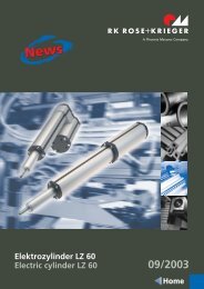
Elektrozylinder LZ 60 Electric cylinder LZ 60......................................................20-28<br />
Merkmale<br />
Features............................................................................20-21<br />
Technische Daten T0echnical Data ...............................................................22-25<br />
Zubehör Accessories .......................................................................25-27<br />
V. Steuerungen Positioning controls<br />
für Multilift/Alpha Colonne<br />
for Multilift/Alpha Colonne................................................2-3<br />
Synchron+Memory<br />
für Multilift/Alpha Colonne<br />
für LAMBDA-Antriebe<br />
Synchron für LAMBDA-Antriebe<br />
Synchron+Memory f. LAMBDA<br />
Synchronisation+Memory<br />
for Multilift/Alpha Colonne................................................4-5<br />
for LAMBDA drives..............................................................6-7<br />
Synchronization for LAMBDA drives..................................8-9<br />
Synchronization+Memory f. LAMBDA...........................10-11<br />
für RKSlimlift for RKSlimlift ...................................................................12-13<br />
Synchron für RKSlimlift Synchronization for RKSlimlift .......................................14-15<br />
Parallel-/Seriellwandler<br />
Parallel-/Serial converter.................................................16-17<br />
SPS-/PC-Datenschnittstelle PLC-PC-data interface .....................................................18-20<br />
RKPowerlift/RKSlimlift/RKEasylift<br />
RKPowerlift/RKSlimlift/ RKEasylift<br />
VI. Systeme<br />
<strong>Systems</strong><br />
RK Easylift RK Easylift ............................................................................2-5<br />
Merkmale<br />
Zubehör<br />
Features................................................................................2-3<br />
Accessories...............................................................................4<br />
IV<br />
V<br />
VI<br />
VII. Preisliste<br />
Price list<br />
VIII. Anhang<br />
Appendix<br />
Fax-Anfrage Fax inquiry ...........................................................................2-3<br />
Wegbeschreibung<br />
How to find RK Rose+Krieger................................................4<br />
Vertretungen Representatives ...................................................................6-9<br />
<strong>Phoenix</strong> <strong>Mecano</strong> <strong>Phoenix</strong> <strong>Mecano</strong> ..............................................................10-11<br />
Programmübersicht<br />
Programme overview......................................................12-13<br />
D-AT 02/2004<br />
I-3<br />
VII<br />
VIII
Produktauswahl<br />
Product presentation<br />
RK Rose+Krieger ist seit mehr als ein Vierteljahrhundert<br />
im Bereich der Verbindungs- und<br />
Positioniersysteme tätig.<br />
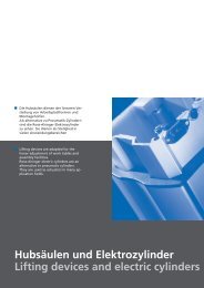
Einen Schwerpunkt bilden hier die Hubsäulen und<br />
Elektrozylinder der Produktsparte <strong>Antriebstechnik</strong>.<br />
Die Hubsäulen eignen sich besonders für die lineare<br />
Verstellung von Schreib- und Labortischen, Montagevorrichtungen<br />
und Handhabungsapparaten. Auf diese<br />
Weise können Arbeitsplattformen und Montagehilfen<br />
in die ergonomisch günstigste Position gebracht<br />
werden.<br />
Die Elektrozylinder stellen eine sehr gute alternative<br />
zu den Pneumatikzylindern dar.<br />
Folgende Vorteile heben sich besonders hervor:<br />
• Gleichmäßiger Lauf auch bei geringen Geschwindigkeiten<br />
• Keine Leckverluste; weniger Energieverbrauch<br />
• Selbsthemmung bei Stillstand<br />
• Teure Zukaufteile wie Magnetventile, Drosseln<br />
oder Wartungseinheiten werden nicht benötigt<br />
• Keine Abluftgeräusche<br />
RK Rose+Krieger has been manufacturing assembly<br />
and positioning systems for over 25 years .<br />
Lifting devices and electric cylinders build an important<br />
part of our drive product range.<br />
Our lifting devices are particularly adapted for the linear<br />
moving of desks, laboratory tables, assembly facilities<br />
and handling devices. They allow for optimal ergonomic<br />
adjustment of work tables and assembly facilities.<br />
Electric cylinders are a very good alternative to pneumatic<br />
cylinders. In particular the following advantages<br />
have been observed:<br />
• regular run also at low speed<br />
• no risk of leak; lower power consumption<br />
• Self-locking device<br />
• Expensive supplementary parts such as solenoid<br />
valves, chokes or maintenance devices are not<br />
necessary.<br />
• No evacuation noises<br />
Mit Hilfe der nebenstehenden Vergleichsdiagramme<br />
wird Ihnen eine Möglichkeit geschaffen, nach unterschiedlichen<br />
Kriterien eine Produktvorauswahl zu<br />
treffen.<br />
Die Angaben beziehen sich auf die Standardprodukte.<br />
Auf Anfrage sind jedoch auch spezielle Ausführungen<br />
(z.B. größerer Hub, größere Hubkraft,<br />
höhere Verfahrgeschwindigkeit usw.) erhältlich.<br />
6.000<br />
4.000<br />
3.500<br />
3.000<br />
2.500<br />
Dynamische Hubkraft [N]<br />
Dynamic lifting power<br />
The diagram on the right will allow you to make a<br />
first choice according to different criteria.<br />
The figures refer to standard models. However,<br />
special models (e.g. with greater travel lengths,<br />
lifting power, lifting speed etc.) can be provided<br />
upon request.<br />
2.000<br />
1.500<br />
1.000<br />
500<br />
0<br />
Multilift<br />
Alpha Colonne<br />
LAMBDA Colonne<br />
RK Powerlift<br />
RK Slimlift<br />
RK Easylift<br />
LAMBDA E-Zyl.<br />
M9<br />
M10<br />
LH10<br />
LH11<br />
LH950<br />
Lh15<br />
LZ60<br />
I-4 RK Rose+Krieger GmbH Postfach 15 64 D-32375 Minden
I<br />
*bei den Katalogangaben sind ±10% Toleranz<br />
zu berücksichtigen<br />
*Please take the tolerance ± of 10% in the<br />
catalogue data into consideration.<br />
100<br />
50<br />
Geschwindigkeit* [mm/s]<br />
Speed* [mm/s]<br />
900<br />
Hub [mm]<br />
Travel [mm]<br />
II<br />
35<br />
700<br />
30<br />
600<br />
25<br />
500<br />
20<br />
400<br />
III<br />
15<br />
300<br />
10<br />
200<br />
5<br />
100<br />
0<br />
Multilift<br />
Alpha Colonne<br />
LAMBDA Colonne<br />
RK Powerlift<br />
RK Slimlift<br />
RK Easylift<br />
LAMBDA E-Zyl.<br />
M9<br />
M10<br />
LH10<br />
LH11<br />
LH950<br />
LH15<br />
LZ60<br />
0<br />
Multilift<br />
Alpha Colonne<br />
LAMBDA Colonne<br />
RK Powerlift<br />
RK Slimlift<br />
RK Easylift<br />
LAMBDA E-Zyl.<br />
M9<br />
M10<br />
LH10<br />
LH11<br />
LH950<br />
LH15<br />
LZ60<br />
IV<br />
1300<br />
Einbaumaß [mm]<br />
Installation height [mm]<br />
1450<br />
Preis [EURO]<br />
Price [EURO]<br />
V<br />
800<br />
450<br />
700<br />
400<br />
600<br />
500<br />
350<br />
300<br />
VI<br />
400<br />
250<br />
300<br />
200<br />
200<br />
100<br />
150<br />
100<br />
VII<br />
0<br />
Multilift<br />
Alpha Colonne<br />
LAMBDA Colonne<br />
RK Powerlift<br />
RK Slimlift<br />
RK Easylift<br />
LAMBDA E-Zyl.<br />
M9<br />
M10<br />
LH10<br />
LH11<br />
LH950<br />
LH15<br />
LZ60<br />
0<br />
Multilift<br />
Alpha Colonne<br />
LAMBDA Colonne<br />
RK Powerlift<br />
RK Slimlift<br />
RK Easylift<br />
LAMBDA E-Zyl.<br />
M9<br />
M10<br />
LH10<br />
LH11<br />
LH950<br />
LH15<br />
LZ60<br />
VIII<br />
D-AT 02/2004<br />
I-5
Anwendungen<br />
Applications<br />
Prüfstand: Höhenverstellung über Multilift-Hubsäulen, Positionierung<br />
von Messeinrichtungen mittels Elektrozylinder<br />
Testing stand: height adjustment by means of Multilift<br />
lifting columns, positioning of measuring systems by means<br />
of electric cylinders<br />
Höhenverstellbarer Geräteträger mit<br />
RKPowerlift (Sonderausführung)<br />
Height-adjustable instrument rack<br />
with RKPowerlift (special version)<br />
Hebebühne aus Multilift-Komponenten<br />
Lifting platform made of Multilift components<br />
I-6 RK Rose+Krieger GmbH Postfach 15 64 D-32375 Minden
Zur Verstellung der Linearkomponenten<br />
aus dem RK-Programm stehen elektrische<br />
Antriebe zur Verfügung, die aber auch für<br />
andere Anwendungen genutzt werden und<br />
zu diesem Zweck in individuelle Systeme<br />
einfließen können.<br />
For the adjustment of linear components<br />
out of the RK product range electric drives<br />
are available that can also be used for other<br />
applications or individual customer<br />
solutions.<br />
Antriebe<br />
Motors<br />
1
Elektronisches Handrad EHL<br />
Electronic Handwheel EHL<br />
Beschreibung<br />
Das Elektronische Handrad EHL stellt eine kostengünstige<br />
Alternative zur herkömmlichen Handverstellung<br />
dar.<br />
Spezieller Einsatzbereich ist z.B. der Einrichtbetrieb<br />
von Linearkomponenten in Gefahrenbereichen und<br />
die Bedienung von schwer zugänglichen Maschinen.<br />
Der Antrieb erfolgt durch einen 24 V Gleichstromgetriebemotor,<br />
der auf Wunsch mit einem Trafosteuerung<br />
kombiniert werden kann.<br />
Hierbei stehen zwei Nenndrehzahlen von 50 und<br />
135 min -1 zur Verfügung.<br />
Description<br />
The Electronic Handwheel EHL is a cost-effective alternative<br />
to the traditional manual adjustment.<br />
It is particularly used for the adjustment of linear components<br />
within danger zones and machines that are<br />
not easily accessible.<br />
The EHL is driven by a 24 V DC motor and can be combined<br />
with a transformer rectifier if requested.<br />
Two speed variations with 50 and 135 rpm are<br />
available.<br />
Merkmale<br />
• Gefertigt nach VDE, Schutzklasse II<br />
• Viele Ausführungsvarianten lieferbar<br />
• Robustes Kunststoffgehäuse<br />
• Farbe: Lichtgrau matt nach RAL 7035,<br />
andere Farben auf Anfrage<br />
Features<br />
• Manufactured according to VDE, protection class I<br />
• Different versions available<br />
• Robust plastic housing<br />
• Colour: light grey mat according to RAL 7035,<br />
other colours upon request<br />
Ausführungen (vergl. Seite 3)<br />
Versions (see page 3)<br />
1<br />
3<br />
5<br />
7<br />
Vorder-u. Rückansicht<br />
Front and rear view<br />
EHL mit Trafo und Handschalter<br />
EHL with transformer and handset<br />
EHL ohne Trafo<br />
EHL with transformer<br />
EHL mit Drehzahlregelung<br />
EHL with speed control<br />
EHL, Drehzahlregelung ohne Gehäuse<br />
EHL, speed control without housing<br />
2<br />
4<br />
6<br />
8<br />
Vorder-u. Rückansicht<br />
Front and rear view<br />
II - 2<br />
RK Rose+Krieger GmbH & Co. KG Postfach 15 64 D-32375 Minden
I<br />
Gabelkopf<br />
Mounting hole<br />
Hinweis: Das EHL sollte grundsätzlich mit<br />
Endschaltern betrieben werden. Hierdurch<br />
wird ein festfahren und damit verbundene<br />
Defekte verhindert.<br />
Please note: the EHL should exclusively be<br />
used with limit switches. This avoids the<br />
guide table reaching the extremity of the<br />
linear unit and further defects, which<br />
could occur due to this error.<br />
II<br />
Motoradapter s. Seite 5<br />
Motor adaptor see p. 5<br />
Anschluss Getriebeflansch<br />
Connection for gear flange<br />
M6-20 tiefe deep<br />
Schnitt A-A<br />
Section A-A-<br />
III<br />
Code No. Type<br />
9.0900<br />
EHL mit Transformator u. Handschalter<br />
EHL with transformer and handset<br />
Drehzahl<br />
Speed<br />
Abtriebsmoment<br />
Starting torque<br />
Gabelkopf Version<br />
Mounting hole S. p. 2<br />
50 [min -1 ] 5,5 Nm ja yes 1<br />
IV<br />
9.0963<br />
9.0911<br />
EHL mit Transformator u. Handschalter<br />
EHL with transformer and handset<br />
EHL mit Transformator u. Handschalter<br />
EHL with transformer and handset<br />
50 [min -1 ] 5,5 Nm nein no 2<br />
135 [min -1 ] 2 Nm ja yes 1<br />
9.0964<br />
EHL mit Transformator u. Handschalter<br />
EHL with transformer and handset<br />
135 [min -1 ] 2 Nm nein no 2<br />
9.0910 EHL ohne Trafo EHL without transformer 50 [min -1 ]* 5,5 Nm ja yes 3<br />
V<br />
9.0960 EHL ohne Trafo EHL without transformer 50 [min -1 ]* 5,5 Nm nein no 4<br />
9.0912 EHL ohne Trafo EHL without transformer 135 [min -1 ]* 2 Nm ja yes 3<br />
9.0962 EHL ohne Trafo EHL without transformer 135 [min -1 ]* 2 Nm nein no 4<br />
9.0944<br />
9.0965<br />
EHL mit Drehzahlregelung u. Trafo<br />
EHL with speed control and transformer<br />
EHL mit Drehzahlregelung u. Trafo<br />
EHL with speed control and transformer<br />
50 [min -1 ] 5,5 Nm ja yes 5<br />
50 [min -1 ] 5,5 Nm nein no 6<br />
VI<br />
9.0945<br />
EHL mit Drehzahlregelung u. Trafo<br />
EHL with speed control and transformer<br />
135 [min -1 ] 2 Nm ja yes 5<br />
9.0966<br />
EHL mit Drehzahlregelung u. Trafo<br />
EHL with speed control and transformer<br />
135 [min -1 ] 2 Nm nein no 6<br />
9.0949<br />
9.0950<br />
EHL mit Drehzahlregelung ohne Gehäuse für Regelung<br />
EHL with speed control without housing for s.c.<br />
EHL mit Drehzahlregelung ohne Gehäuse für Regelung<br />
EHL with speed control without housing for s.c.<br />
50 [min -1 ] 5,5 Nm ja yes 7<br />
135 [min -1 ] 2 Nm ja yes 7<br />
VII<br />
9.0948<br />
Nachrüstsatz für alle EHL mit Trafo<br />
Retrofit kit for all EHL with transformer<br />
kompl. mit Platine, Drehzahlregelung u. Umrüstung<br />
complete with pcb, speed control and adaption<br />
8<br />
*in Verbindung mit RK-Trafosteuerung (ein EHL mit 50min -1 Nenndrehzahl erreicht bei einer Versorgung von 24 VDC ca. 36 min -1 .<br />
Durch Erhöhung der Spannung auf etwa 34 VDC könnten die 50min -1 erreicht werden).<br />
*in connection with the RK transformer control (a EHL with a nominal rpm of 50min -1 reaches 36 min -1 under 24 V DC and can reach<br />
50min -1 under a tension of 34 V DC ).<br />
D-AT 02/2004<br />
II - 3<br />
VIII
Elektronisches Handrad EHL<br />
Electronic Handwheel EHL<br />
Technische Daten<br />
Technical data<br />
Einschaltdauer: 100%<br />
Lastabtriebsmoment: 5,5 Nm bei 50 min -1<br />
2 Nm bei 135 min -1<br />
Thermoschutz: 115°C<br />
Schutzart:<br />
IP20<br />
Uninterrupted operation: 100%<br />
Starting torque:<br />
5,5 Nm at 50 rpm<br />
2 Nm at 135 rpm<br />
Thermal protection: 115°C<br />
Protection mode: IP20<br />
Funktionsbeschreibung Drehzahlregelung<br />
Description of speed control<br />
Potentiometer<br />
Potentiometer<br />
Motordrehrichtung<br />
Sense of rotation<br />
Schleichgang<br />
Creep speed<br />
Bei der Drehzahlregelung handelt es sich um eine<br />
elektronische Lösung zur stufenlosen Einstellung der<br />
Drehzahl mit Hilfe eines Drehpotentiometers.<br />
Eilgang:<br />
Das EHL wird mit der Nenndrehzahl<br />
(50 bzw. 135 min -1 ) betrieben. Das<br />
Drehpotentiometer ist hierbei ohne<br />
Funktion.<br />
Schleichgang: Mittels Drehpotentiometer kann die<br />
Drehzahl stufenlos (0-50 bzw.<br />
0-135 min -1 ) angepaßt werden.<br />
z.B. im Einrichtbetrieb<br />
Eilgang<br />
Fast speed<br />
Anordnung Antrieb/Transformator<br />
Arrangement drive/transformer<br />
This speed control is an electronic device for the continuous<br />
speed adjustment by means of a rotary<br />
potentiometer.<br />
Fast speed: The EHL is run at nominal speed<br />
(50 resp. 135 rpm). In this case the<br />
rotary potentiometer has no function.<br />
Creep speed: By means of a rotary potentiometer<br />
the speed can be continuously<br />
adjusted (0-35 resp. 0-135 rpm)<br />
e.g. for set-up.<br />
Die Anordnung des Antriebs zum Transformator ist je<br />
nach Einbaubedingung veränderbar (in 90°-Schritten<br />
drehbar). Hierbei ist jedoch eine Verlängerung der Anschlusskabel<br />
erforderlich.<br />
Als Option liefern wir das EHL nach Ihren Vorgaben.<br />
Standardausführung siehe Foto auf Seite 2.<br />
The position of drive and transformer can be modified<br />
according to individual conditions of installation<br />
(adjustable, engaging at 90° intervals). However, in<br />
this case the connecting cable has to be extended.<br />
The EHL can also be delivered according to your<br />
requirements. For standard version see photo on<br />
page 2.<br />
II - 4<br />
RK Rose+Krieger GmbH Postfach 15 64 D-32375 Minden
I<br />
Motoradapter für Lineareinheiten<br />
Motor adapter for linear units<br />
Type “E”<br />
EHL<br />
Lineareinheit<br />
Linear unit<br />
II<br />
MD<br />
Motoradapter<br />
Motor adapter<br />
Endschalter<br />
Limit switch<br />
Zur Montage des Motoradapters an einer Lineareinheit<br />
Type E wird ein Muffenklemmstück<br />
“MD” benötigt (im Lieferumfang des<br />
Adapters enthalten).<br />
A "MD" sleeve clamp is required for the<br />
assembly of the motor adaptor onto a linear<br />
unit of type "E" (and is included in the<br />
adaptor delivery set).<br />
III<br />
Code No. für Lineareinheit* for linear unit* Code No. für Lineareinheit* for linear unit*<br />
9.2663 E 30 incl. MD 9.2680 EV / AV 30<br />
9.2664 E 40 incl. MD 9.2671 EV / AV 40<br />
9.2665 E 50 incl. MD 9.2672 EV / AV 50<br />
9.2666 E 60 incl. MD 9.2679 EV 60<br />
9.2682 E80 9.2673 EV / AV 80<br />
9.2667 EP 30 9.2674 COPAS 20<br />
9.2668 EP 40/ COPAS 40 9.2675 COPAS 30<br />
9.2669 EP 50 9.2676 PLS II 30<br />
9.2670 EP 60 9.2677 PLS II 40<br />
9.2683 EP 80 9.2678 PLS II 50<br />
9.2679 PLS II 60<br />
IV<br />
V<br />
Endschalter<br />
Limit switch<br />
Max. Spannung<br />
250 V AC<br />
Max. Schaltstrom<br />
6 A<br />
Max. Einschaltstrom<br />
16 A<br />
Schalthäufigkeit max. 6000/h<br />
Lebensdauer<br />
1x10 7 Schaltzyklen<br />
Achshebelverstellung einrastend um 360°<br />
Schutzart IP 65<br />
Umgebungstemperatur -30°C bis +80°C<br />
* siehe Katalog Linearkomponenten<br />
* see Linear Components catalogue<br />
Max. voltage<br />
250 V AC<br />
Max. constant current 6 A<br />
Max. Starting current 16 A<br />
Switching frequency max. 6000/h<br />
Lifetime<br />
1x10 7 switching cycles<br />
Lever arm adjustment 360° rotation<br />
Protection mode IP 65<br />
Ambient temperature -30°C to +80°C<br />
VI<br />
VII<br />
Code No.<br />
9.1900 Öffner / Schließer Opening / Closing<br />
Type<br />
9.1901 Anschlusskabel 3m für Endschalter, mit PG-Verschraubung Connecting cable (3m) for limit switch, incl. PG connection<br />
D-AT 02/2004<br />
II - 5<br />
VIII
Elektronisches Handrad EHL<br />
Electronic Handwheel EHL<br />
Etikettiermaschine: Die Höhenanpassung wird durch eine<br />
Lineareinheit der Baureihe E mit EHL geregelt.<br />
Labelling machine: The production process is controlled by<br />
means of a linear unit E with EHL.<br />
Bohrautomat: Mit der Drehzahlregelung werden Maschinen<br />
genau justiert und eingerichtet.<br />
Drilling machine: The speed control allows for a precise set-up<br />
and adjustment.<br />
Transfersystem: Antrieb einer Materialzuführung<br />
Transfer system: drive element for feeder unit<br />
II - 6<br />
RK Rose+Krieger GmbH Postfach 15 64 D-32375 Minden
Teleskopierende Hubsäulen können zur<br />
Höhenverstellung von Arbeitsplattformen<br />
und Betriebsmitteln genutzt werden, um<br />
eine ergonomisch günstige Position zu<br />
erreichen. Unterschiedliche Bauformen<br />
und Ausführungen finden sowohl in der<br />
Industrie als auch im Büromöbelbereich<br />
Anwendung.<br />
Telescopic lifting columns are used for the<br />
height adjustment of working platforms or<br />
material in order to fulfil ergonomic<br />
requirements. Due to different design and<br />
speed versions these columns are suitable<br />
for industrial use as well as for the construction<br />
of office furniture.<br />
Hubsäulen<br />
Lifting devices<br />
1
Multilift<br />
Multilift<br />
Ausführung B, m. Ausfräsung<br />
Version B, with milled slots<br />
Beschreibung<br />
Der Multilift dient der stufenlosen Höhenverstellung<br />
von Tischen, Montagearbeitsplätzen, Vorrichtungen<br />
uvm.<br />
Die Hubsäule kann einzeln oder paarweise parallel<br />
betrieben werden.<br />
Für den genauen Gleichlauf mehrerer Antriebe (bis zu<br />
max. 4) ist eine Synchronausführung mit spezieller<br />
Antriebssteuerung erhältlich.<br />
Hubkräfte bis zu 3000 N pro Antrieb sind möglich.<br />
Max. Standardhublänge ist 500 mm (Sonderhübe auf<br />
Anfrage erhältlich).<br />
Der Antrieb besteht aus einem 24 V DC Getriebemotor,<br />
welcher in der Regel mittels einer Steuer-/Trafoeinheit<br />
(230 V AC/120 V DC) versorgt wird.<br />
In Kombination mit der 160 VA Steuerung ist der<br />
Multilift auch für den Medizinalbereich geeignet.<br />
Ausführung A<br />
Version A<br />
Description<br />
The Multilift is used for the continuous height adjustment<br />
of tables, workstations, etc.<br />
The Multilift can be run separately or in parallel pairs.<br />
To guarantee exact synchronization of several drives<br />
(up to 4) a special version with drive control is available.<br />
It is possible to lift up to 3000 N per drive.<br />
Max. Standard travel length is 500 mm (customized<br />
travel lengths available upon request).<br />
The 24 V DC motor is run by means of a control/transformer<br />
unit (230 V AC/120 V DC).<br />
Combined with a 160 VS control, Multilift is also suitable<br />
for use in medical equipments.<br />
Merkmale<br />
• Höhenverstellung von Montagetischen und Vorrichtungen<br />
• Alu-Strangpreßprofil mit Längsnuten<br />
• Vierfache Lagerung mit POM-Gleitlagerschalen<br />
• Leistungsstarker Gleichstrommotor<br />
• Integrierte Endschalterleiste zur Hubbegrenzung<br />
• Selbsthemmung auch bei max. Belastung<br />
• Profiloberfläche hell eloxiert, als Option farbig<br />
pulverbeschichtet<br />
• Einzel- und Synchronsteuerung möglich<br />
• Spezielle Hublängen auf Anfrage<br />
Features<br />
• Height adjustment of assembly tables and devices<br />
• Extruded aluminium profile with longitudinal slots<br />
• Quadruple bearing with POM plain bearing race<br />
• Powerful DC motor<br />
• Integrated limit switch (with Hall sensor at option)<br />
• Self-locking<br />
• Surface anodized natural colour, coloured<br />
powder-coating optional<br />
• Individual or synchronizing control available<br />
• Customized travel lengths on request<br />
III - 2<br />
RK Rose+Krieger GmbH Postfach 15 64 D-32375 Minden
I<br />
Übertragungswelle<br />
transmission shaft<br />
II<br />
Handkurbel<br />
Crank handle<br />
Einbauhöhe installation height<br />
Einbauhöhe installation height -10mm<br />
Einbauhöhe installation height -40mm<br />
Multilift manuell<br />
Version rechts right<br />
seitlicher Buchsenausgang<br />
bei<br />
Synchronsteuerung<br />
(Kabellänge 2,5m)<br />
lateral exit hub in<br />
for synchronizing<br />
control<br />
(cable length 2,5 m)<br />
Multilift manuell<br />
Version links left<br />
III<br />
IV<br />
BLOCAN-<br />
Nutgeometrie<br />
Slot geometry<br />
Schraubkanal M8<br />
Self tap M8<br />
Ansicht “A”<br />
View “A”<br />
V<br />
Code No.<br />
qab 00 ac 10 0470<br />
qab 00 ac 11 0470<br />
Type<br />
Multilift man.<br />
Version links left<br />
Multilift man.<br />
Version rechts right<br />
Gesamthub<br />
Total travel<br />
Einbauhöhe<br />
Inst. height<br />
qab 13 hg 0 _ 0 355 Multilift 350 355 mm 550 mm<br />
max. Hubgeschw.<br />
Max. lifting speed<br />
max. Hubkraft<br />
Max. load<br />
Gewicht<br />
Weight<br />
470 mm 695 mm – 1.000 N 11,2 kg<br />
470 mm 695 mm – 1.000 N 11,2 kg<br />
qab 13 hg 0 _ 0 400 Multilift 400 400 mm 595 mm 10,0 kg<br />
8 mm / s 3.000 N<br />
qab 13 hg 0 _ 0 450 Multilift 450 452 mm 650 mm 10,8 kg<br />
qab 13 hg 0 _ 0 500 Multilift 500 498 mm 695 mm 11,5 kg<br />
qab 26 hg 0 _ 0 355 Multilift 350 s 355 mm 550 mm<br />
qab 26 hg 0 _ 0 400 Multilift 400 s 400 mm 595 mm 10,0 kg<br />
16 mm / s 1.000 N<br />
qab 26 hg 0 _ 0 450 Multilift 450 s 452 mm 650 mm 10,8 kg<br />
qab 26 hg 0 _ 0 500 Multilift 500 s 498 mm 695 mm 11,5 kg<br />
9,1 kg<br />
9,1 kg<br />
VI<br />
VII<br />
D-AT 02/2004<br />
Ausführung (siehe Abbildungen Seite 2) Version (see illustrations on page 2)<br />
1 = B (mit Ausfräsung) 1 = version B (with milled slots)<br />
2 = A (ohne Ausfräsung) 2 = version A (without milled slots)<br />
3 = B für Synchronsteuerung 3 = version B for synchronizing control<br />
4 = A für Synchronsteuerung 4 = version A for synchronizing control<br />
farbige Pulverbeschichtungen<br />
auf Anfrage<br />
colour powder-coated<br />
upon request<br />
III - 3<br />
VIII
Multilift<br />
Multilift<br />
Technische Daten<br />
Technical data<br />
Spannung<br />
24 V DC<br />
Power supply<br />
24 V DC<br />
Leistungsaufnahme<br />
120 W<br />
Power consumption<br />
120 W<br />
Schutzart<br />
IP20<br />
Protection mode<br />
IP20<br />
Umgebungstemperatur<br />
-20°C bis +60°C<br />
Ambient temperature<br />
-20°C to +60°C<br />
Druckkraft*<br />
wahlweise 3.000/1.000 N<br />
Compressive force*<br />
3.000/1.000 N at option<br />
Zugkraft*<br />
Gleichlauf b. Synchronst.<br />
max. 1.000 N (mit Druckod.<br />
Montageplatte unten)<br />
0-2 mm / 0-4 mm<br />
Tensile force*<br />
Synchronism<br />
max. 1.000 N (with<br />
compression plate or lower<br />
assembly plate)<br />
0-2 mm / 0-4 mm<br />
* Zur Beachtung<br />
Der Multilift ist so konzipiert, dass ein Verschrauben<br />
mit dem Untergrund (Vierkantrohr, Platte etc.)<br />
notwendig ist. Nur so ist gewährleistet, dass die<br />
Druckkräfte aufgenommen werden können.<br />
Soll der Multilift für Zugbelastungen eingesetzt<br />
werden, muß eine “Druckplatte” oder eine “Montageplatte<br />
unten für Zugbelastung”(siehe Seite 6)<br />
verwendet werden.<br />
* Please note<br />
The Multilift has been designed in a way that it is<br />
necessary to fix it on the ground (square tube, plate<br />
etc.). This is the only way to guarantee optimum<br />
pressure absorption.<br />
Should the Multilift be used for tensile loads, the<br />
compression plate or the lower assembly plate for<br />
tensile force have to be used (see page 6).<br />
Einschaltdauer<br />
Die Hubsäulen sind nicht für den Dauerbetrieb ausgelegt.<br />
Die max. Einschaltdauer unter Nennbelastung<br />
darf 10% nicht überschreiten (max. 2 Min.<br />
Betriebszeit,18 Min. Ruhezeit).<br />
Duty cycle<br />
The lifting columns are not designed for constant<br />
operation. The maximum operating time under a<br />
nominal load may not exceed 10% (max. 2 minutes<br />
operating time for 18 min. break for instance).<br />
Leistungsdiagramm<br />
Relation zwischen:<br />
Hubkraft-Hubgeschwindigkeit<br />
Die Absenkgeschwindigkeit entspricht<br />
etwa der Leerlaufgeschwindigkeit.<br />
Performance diagram<br />
Ratio:<br />
Lifting force-Lifting speed.<br />
Descending speed corresponds to<br />
no-load operation.<br />
20<br />
15<br />
10<br />
5<br />
v [mm/s]<br />
1000 N<br />
3000 N<br />
500 1000 1500 2000 2500 3000 F [N]<br />
III - 4<br />
RK Rose+Krieger GmbH Postfach 15 64 D-32375 Minden
I<br />
Seitliche Belastungen<br />
Bending moments<br />
Belastungstabelle Multilift: Hub 355 mm<br />
Load diagram Multilift: travel length 355 mm<br />
F [N]<br />
3000<br />
Belastung dynamisch dynamic load<br />
Belastung statisch static load<br />
II<br />
L<br />
F<br />
2800<br />
2600<br />
Hubgeschwindigkeit<br />
lifting speed<br />
8 mm/s<br />
2400<br />
2200<br />
2000<br />
1800<br />
III<br />
1600<br />
L<br />
F<br />
1400<br />
1200<br />
1000<br />
800<br />
IV<br />
600<br />
400<br />
200<br />
Hubgeschwindigkeit<br />
lifting speed<br />
16 mm/s<br />
0 0,1 0,2 0,3 0,4 0,5 0,6 0,7 0,8 0,9 1,0 L [m]<br />
V<br />
Parallellauf<br />
Bei der Standardausführung können auch zwei Multilifte<br />
parallel verfahren werden. Im Betrieb können sich<br />
unterschiedliche Hubstellungen ergeben. Mittels Anfahren<br />
der Endlagen wird wieder eine Nivellierung erreicht.<br />
Parallel operation<br />
Two standard Multilifts can also be moved in parallel.<br />
During operation the two Multilifts might reach different<br />
lifting positions. In this case they can be levelled<br />
by moving both Multilifts to the end position.<br />
VI<br />
Synchronlauf<br />
Zwei bis vier Säulen werden im Synchronlauf verfahren.<br />
Die Steuerung (siehe Seite 8) in Verbindung mit<br />
eingebauten Sensoren gewährleistet den Gleichlauf.<br />
Dies bewirkt eine dauernde Niveauanpassung aller<br />
Säulen in beiden Fahrrichtungen auch bei unterschiedlicher<br />
Belastung. Die Gleichlaufgenauigkeit<br />
(Gleichlauftoleranz) ist abhängig von der Hubgeschwindigkeit<br />
und beträgt: 0-2 mm bei der Ausführung<br />
8 mm/s bzw. 0-4 mm bei der Ausführung 16 mm/s.<br />
Eine Memoryfunktion ist möglich.<br />
Synchronization<br />
Two to four columns are operated in parallel. The positioning<br />
control (see page 8) with integrated sensors<br />
guarantees synchronism. Thus all columns are constantly<br />
levelled out to remain on the same level, independent<br />
of the load. The accuracy of synchronization<br />
(tolerance) for the slow version is 0-2 mm resp. 0-4 mm<br />
for the fast version, depending on the lifting speed .<br />
Three different lifting positions can be memorized.<br />
VII<br />
D-AT 02/2004<br />
III - 5<br />
VIII
Multilift<br />
Multilift<br />
Optionen<br />
• Spezielle Hublängen<br />
• Höhere Geschwindigkeiten<br />
• Ausführung für Zugkraft<br />
• Montagezubehör<br />
• Spezielle Farben<br />
Options<br />
• Customized travel lengths<br />
• Higher speed<br />
• Special version for tensile loads<br />
• Accessories for assembly<br />
• Special colours<br />
Montageplatte/Druckplatte<br />
Die Montageplatte in den Ausführungen “oben”<br />
und “unten” dienen zur einfachen aufgesetzten<br />
Montage des Multiliftes.<br />
Die Druckplatte (oder Montageplatte unten) ist<br />
erforderlich, wenn die Druckkräfte nicht vom<br />
Untergrund aufgenommen werden können, z.B. bei<br />
waagerechtem Einbau ohne Gegendruck (siehe auch<br />
Beschreibung Seite 4).<br />
Assembly plate/Compression plate<br />
The upper and lower assembly plates enable the<br />
easy fixation of the Multilift.<br />
The compression plate (or lower assembly plate) becomes<br />
necessary when the loads cannot be absorbed<br />
by the ground, e.g. In the case of horizontal installation<br />
without back pressure (see also description on<br />
page 4).<br />
Material: St37-2, schwarz pulverbeschichtet<br />
Befestigungssatz galv. verzinkt<br />
Lieferumfang: 1x Montage-/ bzw. Druckplatte<br />
Befestigungssatz<br />
Material:<br />
Delivery set:<br />
St37-2, black power-coating<br />
fixation set galvanized<br />
1 assembly/resp. compression plate<br />
fixation set<br />
Senkung<br />
counterbore<br />
DIN74 – H m 8<br />
Senkung counterbore<br />
DIN74 – H m 8<br />
Montageplatte unten<br />
Lower assembly plate<br />
Montageplatte oben<br />
Upper assembly plate<br />
Code No. Ausführung Version<br />
Druckplatte<br />
Compression plate<br />
*Montage kann nur werkseitig erfolgen.<br />
*To be assembled by RK Rose+Krieger production dept.<br />
qzd 02 0017<br />
qzd 02 0110*<br />
qzd 02 0018<br />
qzd 02 0019*<br />
qzd 02 0149<br />
Montageplatte unten für Druckbelastung<br />
lower assembly plate for compression force<br />
Montageplatte unten für Zugbelastung<br />
lower assembly plate for tensile force<br />
Montageplatte oben<br />
upper assembly plate<br />
Druckplatte für Zugbelastung<br />
compression plate for tensile force<br />
Druckplatte für Druckbelastung<br />
compression plate for compression force<br />
III - 6<br />
RK Rose+Krieger GmbH Postfach 15 64 D-32375 Minden
I<br />
Adapterleiste<br />
Um die Standfestigkeit zweier Multilifte der<br />
Ausführung B (siehe Seite 2) zu erhöhen, können<br />
Querstreben aus dem BLOCAN ® Profil-Montagesystem<br />
eingesetzt werden. Die Adapterleiste ist für Profil<br />
F-30x60 und S-40x80 geeignet.<br />
Material: AlMgSi 0,5<br />
Befestigungssatz galv. verzinkt<br />
Lieferumfang: 2x Adapterleiste<br />
Befestigungssatz<br />
Adapter strip<br />
In order to increase the stability of two Multilifts<br />
version B (see page 2) cross struts from the BLOCAN ®<br />
Profile Assembly System can be inserted. The adapter<br />
strip is suitable for profiles F-30x60 and S-40x80.<br />
Material: AlMgSi 0.5<br />
fixation set galvanized<br />
Delivery set: 2 adapter strips<br />
fixation set<br />
II<br />
III<br />
Adapterleiste<br />
Adapter strip<br />
IV<br />
BLOCAN-Profil als Querstrebe<br />
BLOCAN profile as cross strut<br />
Code No. Ausführung Version<br />
qzd 02 0020<br />
Adapterleiste für BLOCAN ® -Profil S-40x80/F-30x60 adapter strip for BLOCAN profile S-40x80/F-30x60<br />
4.035000 _ _ _ _ Profil* S-40x80, Zuschnitt nach Wunsch profile* S-40x80, cut upon request<br />
4.305000 _ _ _ _ Profil* F-30x60, Zuschnitt nach Wunsch profile* F-30x60, cut upon request<br />
V<br />
Länge (lichte Weite zwischen den Multiliften -2mm)<br />
length (clearance between Multilifts -2mm)<br />
*Maße der Profile siehe BLOCAN ® -Katalog<br />
*For dimensions of profiles see BLOCAN ® catalogue<br />
Druckstück<br />
Das Druckstück wird stirnseitig mit dem Innenprofil<br />
verschraubt und dient dem leichten Übergleiten von<br />
lose aufliegenden, zu hebenden Teilen.<br />
Material: PA, schwarz<br />
Befestigungssatz galv. verzinkt<br />
Lieferumfang: Druckstück mit Befestigungsmaterial<br />
Compression plate<br />
The compression plate is screwed up onto the front<br />
side of the profile and insures the easy motion of non<br />
fixed element positioned on the profile and having to<br />
be lifted up.<br />
Material: PA, black<br />
galvanised fixation set<br />
Delivery set: pressure plate with fixation elements<br />
VI<br />
VII<br />
Code No. Ausführung Version<br />
D-AT 02/2004<br />
qzd 020 155<br />
Druckstück Compression plate<br />
III - 7<br />
VIII
Multilift<br />
Multilift<br />
Steuerungen<br />
Positioning controls<br />
Abmessungen und weitere technische<br />
Angaben siehe<br />
Seite V-2-5.<br />
For dimensions and further<br />
technical details see pages V-2-5.<br />
Eingangsspannung 230 V AC<br />
Ausgangsspannung 24 V DC<br />
Input voltage 230 V AC<br />
Output voltage 24 V DC<br />
Code No. Ausführung Version<br />
qza 07 c 13 ax 021<br />
qza 02 c 03 ac 021<br />
qza 07 c 07 bc 011<br />
qza 07 c 07 bd 011<br />
qza 04 e 07 am 011<br />
qza 04 e 07 ap 011<br />
Trafosteuerung ML/AC 120 VA, bis 3.000 N Gesamthubkraft<br />
transformer control ML/AC 120 VA, lifting power up to 3.000 N<br />
Trafosteuerung ML/AC 160 VA, bis 6.000 N Gesamthubkraft<br />
transformer control ML/AC 160 VA, lifting power up to 6.000 N<br />
Synchronsteuerung ML/AC 150 VA 2+1, bis 4.000 N Gesamthubkraft<br />
synchronizing control ML 150 W 2+1, lifting power up to 4.000 N<br />
Synchronsteuerung ML/AC 150 VA 4+1, bis 4.000 N Gesamthubkraft<br />
synchronizing control ML/AC 150 VA 4+1, lifting power up to 4.000 N<br />
Synchronsteuerung ML/AC 150 VA 2+1, bis 4.000 N Gesamthubkraft,<br />
mit Netzfreischaltung<br />
synchronizing control 150 VA 2+1, lifting power up to 4.000 N ,<br />
with power cutoff plug<br />
Synchronsteuerung ML/AC 150 VA 4+1, bis 4.000 N Gesamthubkraft,<br />
mit Netzfreischaltung<br />
synchronizing control 150 W 4+1, lifting power up to 4.000 N,<br />
with mains power switch<br />
bis 2 Antriebe steuerbar<br />
controls up to 2 drives<br />
bis 2 Antriebe steuerbar<br />
controls up to 2 drives<br />
2 Antriebe synchron + 1 Antrieb getrennt steuerbar*<br />
2 synchronous drives + 1 drive separately controllable*<br />
4 Antriebe synchron + 1 Antrieb getrennt steuerbar*<br />
4 synchronous drives + 1 drive separately controllable*<br />
2 Antriebe synchron + 1 Antrieb getrennt steuerbar<br />
2 synchronous drives + 1 drive separately controllable<br />
4 Antriebe synchron + 1 Antrieb getrennt steuerbar<br />
4 synchronous drives + 1 drive separately controllable<br />
Zubehör für Trafosteuerung<br />
Accessories for transformer control<br />
qzd 02 00 83<br />
Befestigungsplatte ML/AC 120 VA<br />
fixing plate ML/AC 120 VA<br />
Steuerung wird auf die Befestigungsplatte geschoben<br />
the transformer control is slided onto it<br />
Zubehör für Synchronsteuerung<br />
Accessories for synchronizing control<br />
qzd 020 035<br />
Parallel-/Seriellwandler (Produktbeschreibung siehe Seite V-16-17)<br />
Parallel-/serial converter (product description, see page V-16-17)<br />
z.B. zur Ansteuerung der Synchronsteuerung über SPS<br />
eg. to drive the synchronous controller via a PLC<br />
*Bei Bildschirmarbeitsplätzen wird der Einsatz der Synchronsteuerung mit Netzfreischaltung empfohlen<br />
*The use of synchronous control with automatic stand-by is recommended in case of workstations fitted with monitors.<br />
Foto Fa. RK Rose+Krieger, Minden<br />
CAD-Tisch mit stufenloser Höhen- und Neigungsverstellung.<br />
Durch die Memory-Funktion können bevorzugte Positionen<br />
immer wieder eingestellt werden. Siehe auch Seite VI-6.<br />
CAD table with continuous height and angle adjustment. The<br />
required position can be memorized. See also pages VI-6.<br />
Foto Fa. Andek, Rinteln<br />
Höhenverstellbarer Arbeitstisch mit Spiegelrasterleuchte<br />
und Wartungseinheit<br />
Height adjustable work table with reflector lamp.<br />
III - 8<br />
RK Rose+Krieger GmbH Postfach 15 64 D-32375 Minden
I<br />
Handschalter/Handkurbel<br />
Handset/Crank handle<br />
L= 750 mm<br />
Code No. Ausführung Version<br />
II<br />
Handkurbel und Übertragungswelle für Multilift manuell<br />
Handle and Transmission shaft for Multilift manuell<br />
qzd 100 081 0750<br />
Handkurbel, Ø10mm, L= 750 mm<br />
handle, Ø10 mm, L= 750 mm<br />
850 mm Gesamtlänge, incl. 2 Halter<br />
total length 850 mm, incl. 2 support clips<br />
qzd 020 171 2000<br />
Handschalter für Trafosteuerung<br />
qzb 02 c 03 ab 031<br />
Übertragungswelle, L= 2000 mm<br />
transmission shaft, L= 2000 mm<br />
handset for transformer control<br />
Handschalter mit 1m Spiralkabel – 2 Funktionstasten<br />
handset with 1m helix cable – 2 function keys<br />
kann bei Bedarf gekürzt werden (lichtes Maß zwischen den<br />
Multiliften +48 mm) it can be reduced if necessary<br />
(installation distance between the Multilift + 48 mm)<br />
bis zu 2 Antriebe gemeinsam steuerbar<br />
controls up to 2 drives simultaneously<br />
III<br />
qzb 02 c 03 ad 031<br />
Handschalter mit 1m Spiralkabel – 6 Funktionstasten<br />
handset with 1m helix cable – 6 function keys<br />
2 Antriebe getrennt oder gemeinsam steuerbar<br />
controls 2 drives, separate or joint<br />
qzb 02 c 03 ab 011<br />
Infrarot-Fernbedienung – 2 Funktionstasten<br />
remote control – 2 function keys<br />
bis zu 2 Antriebe gemeinsam steuerbar<br />
controls up to 2 drives simultanously<br />
qzb 02 c 03 ad 011<br />
qzb 02 a 03 ab 041<br />
Infrarot-Fernbedienung – 6 Funktionstasten<br />
remote control – 6 function keys<br />
Undercover Handschalter m. Steckerausführung “winklig”<br />
Undercover handset with angular plug<br />
2 Antriebe getrennt oder gemeinsam steuerbar<br />
controls 2 drives, separate or joint<br />
bei Trafosteuerung 120 VA ein Antrieb steuerbar<br />
bei Trafosteuerung 160 VA bis zu zwei Antriebe steuerbar<br />
controls one drive with a 120 VA transformer control controls up<br />
to 2 drives with a 160 VA transformer control<br />
IV<br />
Handschalter für Synchronsteuerung<br />
handset for synchronizing control<br />
qzb 02 c 03 ah 031<br />
Handschalter mit 1m Spiralkabel – 9 Funktionstasten<br />
handset with 1m helix cable – 9 function keys<br />
bis zu 4 Antriebe steuerbar, mit Memoryfunktionen<br />
controls up to 4 drives, with memory functions<br />
qzb 02 c 03 ag 011<br />
Infrarot-Fernbedienung – 11 Funktionstasten<br />
remote control – 11 function keys<br />
Zubehör für Handschalter mit Spiralkabel (nur Trafosteuerung)<br />
qzd 000 072 Halterung für Handschalter Support for handset<br />
bis zu 4 Antriebe steuerbar, mit Memoryfunktionen<br />
controls up to 4 drives, with memory functions<br />
Accessories for handset with helix cable (for transformer control only)<br />
V<br />
Zubehör für Infrarot-Fernbedienungen<br />
Accessories for remote control<br />
qzd 02 00 22<br />
separate Steckdose von Infrarot-Fernbedienung schaltbar<br />
separate socket, can be switched on with remote control<br />
Schaltleistung 850 W<br />
rupturing capacity 850 W<br />
Fußschalter (nicht in Verbindung mit Synchronisation)<br />
Foot switch (not for synchronization)<br />
qzb 02 c 01 ae 034<br />
Fußschalter – 2 Funktionstasten<br />
Foot switch – 2 function keys<br />
bis zu 2 Antriebe steuerbar<br />
controls up to 2 drives<br />
VI<br />
VII<br />
VIII<br />
D-AT 02/2004<br />
III - 9
Alpha Colonne<br />
Alpha Colonne<br />
Beschreibung<br />
Die Hubsäule Alpha Colonne ist ein Teleskopantrieb,<br />
welcher zum stufenlosen Heben und Senken von<br />
Tischen, medizinischen Geräten, PC-Panels uvm.<br />
geeignet ist.<br />
Aufgrund der Ausführung in formschönem,<br />
eloxiertem Aluminiumprofil ist keine zusätzliche<br />
Außenverkleidung der Säule nötig.<br />
Das Hubsäulenprogramm Alpha Colonne besteht aus<br />
zwei Baugrößen: “Medium” und “Large”. Durch die<br />
größere Dimensionierung der Large-Ausführung (siehe<br />
Seite 11) lassen sich entsprechend höhere Seitenkräfte<br />
aufnehmen.<br />
Der Einsatzbereich ist ausgelegt für Hubkräfte bis<br />
3.000 N bei max. 700 mm Hublänge. Lieferbar sind<br />
Hubgeschwindigkeiten bis zu 20 mm/s (1.000 N).<br />
Der Antrieb besteht aus einem 24 V DC Getriebemotor,<br />
welcher in der Regel mittels einer externen<br />
Steuer-/Trafoeinheit (120 V AC/230V AC-24 V DC) oder<br />
bei der Ausführung mit integriertem Trafo direkt mit<br />
120 oder 230 V AC versorgt wird.<br />
*Mehrsäulensynchronisation >2 Säulen sollten nur nach<br />
Rücksprache mit RK Rose+Krieger erfolgen.<br />
* Synchronisation of more than 2 columns should only occur after<br />
consulting RK Rose+Krieger.<br />
Description<br />
The Alpha Colonne is a telescopic lifting device for the<br />
continuous height adjustment of tables, medical<br />
equipment, PC panels etc.<br />
Due to the well designed anodized aluminium profile,<br />
the column does not need any other external panelling.<br />
The Alpha Colonne is available in two sizes:“Medium”,<br />
and “Large”. Due to its bigger dimensions the “Large”<br />
version is able to take higher side moments.<br />
It can be used for loads of up to 3.000 N and a max. travel<br />
length of 700 mm. Different speed versions of up to<br />
20 mm/s (1.000 N) are available.<br />
The 24 V DC geared motor is run by means of an external<br />
positioning/transformer unit (120 V AC/230V<br />
AC-24 V DC) or, in the case of an integrated transformer,<br />
directly supplied with 120 or 230 V AC.<br />
Merkmale<br />
• Höhenverstellung von Tischen und Vorrichtungen<br />
• Voreingestellte Gleitereinheiten garantieren Spielfreiheit<br />
auch nach jahrelangem Betrieb<br />
• Einbaumaßkorrektur ±3 mm<br />
• Eingebaute Endschalter<br />
• Selbsthemmung auch unter max. Belastung<br />
• Für Zug- und Druckbelastung geeignet<br />
• In der Säule integrierter Motor<br />
• Formschönes Design in eloxiertem Aluminium<br />
• Glatte Oberflächen für effektive Reinigung<br />
• Einzel- und Synchronsteuerung* möglich<br />
Features<br />
• Height adjustment of tables and other facilities<br />
• Adjusted sliding guides guarantee zero backlash<br />
even after years of operation<br />
• Assembly dimension can be corrected by ±3 mm<br />
• Integrated limit switches<br />
• Self-locking even under max. load<br />
• Takes compressive and tensile forces<br />
• Motor integrated in the column<br />
• Attractive design, anodized aluminium<br />
• Smooth surface for easy cleaning<br />
• Separate or synchronizing control* available<br />
III - 10<br />
RK Rose+Krieger GmbH Postfach 15 64 D-32375 Minden
I<br />
ACM “Medium”<br />
ACL “Large”<br />
A 150 190<br />
B 130 170<br />
C 9 11<br />
D 128 163<br />
II<br />
E 114 145<br />
F 100 128<br />
Anschlussstecker 24 V DC<br />
Netzstecker 120/230 V AC<br />
(bei Ausführung mit<br />
interner Steuerung)<br />
Connecting plug 24 V DC<br />
Mains plug 120/230 V AC<br />
(for integrated positioning<br />
control)<br />
III<br />
IV<br />
Einbauhöhe=Hub+120<br />
Installation height=Travel+120<br />
Hub<br />
Travel<br />
Code No.<br />
Type<br />
Gesamthub<br />
Total travel<br />
Einbauhöhe<br />
Inst. Height<br />
max. Hubgeschw.<br />
Max. lifting speed<br />
max. Hubkraft<br />
Max. Load<br />
qk_ 08 bc 0_ 0200 Alpha Colonne AC_ - 200 200 mm 320 mm<br />
qk_ 08 bc 0_ 0300 Alpha Colonne AC_ - 300 300 mm 420 mm<br />
qk_ 08 bc 0_ 0400 Alpha Colonne AC_ - 400 400 mm 520 mm<br />
qk_ 08 bc 0_ 0500 Alpha Colonne AC_ - 500 500 mm 620 mm<br />
qk_ 08 bc 0_ 0600 Alpha Colonne AC_ - 600 600 mm 720 mm<br />
qk_ 08 bc 0_ 0700 Alpha Colonne AC_ - 700 700 mm 820 mm<br />
qk_ 12 bb 0_ 0200 Alpha Colonne AC_ - 200 200 mm 320 mm<br />
qk_ 12 bb 0_ 0300 Alpha Colonne AC_ - 300 300 mm 420 mm<br />
qk_ 12 bb 0_ 0400 Alpha Colonne AC_ - 400 400 mm 520 mm<br />
qk_ 12 bb 0_ 0500 Alpha Colonne AC_ - 500 500 mm 620 mm<br />
qk_ 12 bb 0_ 0600 Alpha Colonne AC_ - 600 600 mm 720 mm<br />
qk_ 12 bb 0_ 0700 Alpha Colonne AC_ - 700 700 mm 820 mm<br />
qk_ 18 ba 0_ 0200 Alpha Colonne AC_ - 200 200 mm 320 mm<br />
qk_ 18 ba 0_ 0300 Alpha Colonne AC_ - 300 300 mm 420 mm<br />
qk_ 18 ba 0_ 0400 Alpha Colonne AC_ - 400 400 mm 520 mm<br />
qk_ 18 ba 0_ 0500 Alpha Colonne AC_ - 500 500 mm 620 mm<br />
qk_ 18 ba 0_ 0600 Alpha Colonne AC_ - 600 600 mm 720 mm<br />
qk_ 18 ba 0_ 0700 Alpha Colonne AC_ - 700 700 mm 820 mm<br />
8 mm / s 3.000 N<br />
12 mm / s 2.000 N<br />
18 mm / s 1.000 N<br />
V<br />
VI<br />
VII<br />
Alpha Colonne<br />
t = Medium ACM<br />
v = Large ACL<br />
D-AT 05/2002<br />
Ausführung Version<br />
1 = Standard<br />
3 = mit Hall-Sensor (Einbauhöhe+17mm) with Hall sensor (installation height+17mm)<br />
4 = interne Steuerung (ab 300 mm Hub) integrated transformer (ex 300 mm travel)<br />
III - 11<br />
VIII
Alpha Colonne<br />
Alpha Colonne<br />
Technische Daten<br />
Spannung wahlweise 24 V DC /<br />
120/230 V AC<br />
Leistungsaufnahme 120 VA<br />
Schutzart<br />
IP30<br />
Umgebungstemperatur -20°C bis +60°C<br />
Hubkraft wahlweise 1.000/2.000/<br />
3.000 N<br />
Gleichlauf b. Synchronst. 0-4 mm / 0-3 mm / 0-2 mm<br />
Technical data<br />
Voltage<br />
Current consumption<br />
Protection mode<br />
Ambient temperature<br />
Load<br />
Parallelism<br />
(synchronizing control)<br />
24 V DC / 120/230 V AC<br />
at choice<br />
120 VA<br />
IP30<br />
-20°C to +60°C<br />
1.000/2.000/3.000 N<br />
at choice<br />
0-4 mm / 0-3 mm / 0-2 mm<br />
Gewichte*<br />
Weight*<br />
Standard Alpha Colonne ACM Alpha Colonne ACL<br />
Hub Travel 200 mm 6,5 kg 10,0 kg<br />
Hub Travel 300 mm 8,0 kg 12,5 kg<br />
Hub Travel 400 mm 9,5 kg 15,0 kg<br />
Hub Travel 500 mm 11,0 kg 17,5 kg<br />
Hub Travel 600 mm 12,5 kg 20,0 kg<br />
Hub Travel 700 mm 14,0 kg 22,5 kg<br />
*Bei Ausführung mit interner Steuerung; Mehrgewicht = 1kg<br />
*for version with integrated positioning control; extra weight = 1kg<br />
Einschaltdauer<br />
Die Hubsäulen sind nicht für den Dauerbetrieb ausgelegt.<br />
Die max. Einschaltdauer unter Nennbelastung<br />
darf 20% (2 Min. Betriebszeit, 8 Min. Ruhezeit)<br />
nicht überschreiten.<br />
Duty cycle<br />
The lifting columns are designed for intermittent<br />
service. The maximum operating time under a nominal<br />
load may not exceed 20% (2 min. operating time<br />
for 8 min. break for instance).<br />
Leistungsdiagramm<br />
Relation zwischen:<br />
Hubkraft-Hubgeschwindigkeit-Stromaufnahme<br />
Die Absenkgeschwindigkeit entspricht<br />
etwa der Leerlaufgeschwindigkeit.<br />
I [A]<br />
v [mm/s]<br />
v [mm/s]<br />
I [A]<br />
Performance diagram<br />
Ratio:<br />
Lifting power-Speed-Current consumption<br />
Descending speed corresponds to no-load<br />
operation.<br />
5<br />
20<br />
AC, 2000 N<br />
AC, 3000 N<br />
4<br />
3<br />
2<br />
15<br />
10<br />
AC, 1000 N<br />
AC, 2000 N<br />
AC, 3000 N<br />
1<br />
5<br />
0<br />
500 1000 1500 2000 2500 3000 3500 4000 F [N]<br />
III - 12<br />
RK Rose+Krieger GmbH & Co. KG Postfach 15 64 D-32375 Minden
I<br />
Seitliche Belastung<br />
Durch die Ausführung der Hubsäule mit drei ineinander<br />
geführten Alu-Vierkant-Spezialprofilen können<br />
auch exzentrische Belastungen aufgenommen werden.<br />
Da die Größe der Belastung von mehreren Faktoren<br />
abhängig ist, wie z.B. Baugröße, Hublänge, Auslenkung<br />
usw. wird auf die Darstellung der Seitenlastdiagramme<br />
verzichtet.<br />
Bei außermittigen Anwendungen hilft Ihnen RK<br />
Rose+Krieger und/oder die Vertretung gerne mit einer<br />
maßgeschneiderten Lösung weiter.<br />
Optionen<br />
• Sonderausführungen (spezielle Längen, Befestigungsbohrungen<br />
usw.)<br />
• Größere Hubkraft und Geschwindigkeit<br />
• Spezielles Außenprofil<br />
• Eingebaute Impulsgeber<br />
• Integrierte Steuerung für Haupt- und Zusatzantrieb<br />
Bending moments<br />
The lifting column can also take eccentric loads due to<br />
its structure containing three specially designed telescoping<br />
aluminium square tubes. As the max. load depends<br />
on different factors such as size, travel length,<br />
excursion etc. we have refrained from presenting a<br />
diagram illustrating the admissible bending moments.<br />
In the case of eccentric applications RK Rose+Krieger<br />
and/or the distributor in charge of your area will be<br />
pleased to offer you an individual solution.<br />
Options<br />
• Special versions (customized lengths, mounting<br />
holes etc.)<br />
• Higher lifting power and speed<br />
• Specially designed outer profile<br />
• Integrated encoder<br />
• Integrated control for main and additional drive<br />
II<br />
III<br />
IV<br />
V<br />
VI<br />
VII<br />
D-AT 05/2002<br />
III - 13<br />
VIII
Alpha Colonne<br />
Alpha Colonne<br />
Steuerungen<br />
Positioning controls<br />
Abmessungen und weitere technische<br />
Angaben siehe<br />
Seite V-2-5.<br />
For dimensions and further<br />
technical details see pages V-2-5.<br />
Eingangsspannung 230 V AC<br />
Ausgangsspannung 24 V DC<br />
Input voltage 230 V AC<br />
Output voltage 24 V DC<br />
Code No. Ausführung Version<br />
qza 07 c 13 ax 021<br />
qza 02 c 03 ac 021<br />
qza 07 c 07 bc 011<br />
qza 07 c 07 bd 011<br />
qza 04 e 07 am 011<br />
qza 04 e 07 ap 011<br />
Trafosteuerung ML/AC 120 VA, bis 3.000 N Gesamthubkraft<br />
transf. control ML/AC 120 VA, lifting power up to 3.000 N<br />
Trafosteuerung ML/AC 160 VA, bis 6.000 N Gesamthubkraft<br />
transf. control ML/AC 160 VA, lifting power up to 6.000 N<br />
Synchronsteuerung ML/AC 150 VA 2+1, bis 4.000 N Gesamthubkraft<br />
Synchr. control ML/AC 150 W 2+1, lifting power up to 4.000 N<br />
Synchronsteuerung ML/AC 150 VA 4+1, bis 4.000 N Gesamthubkraft<br />
Synchr. control ML/AC 150 VA 4+1, lifting power up to 4.000 N<br />
Synchronsteuerung ML/AC 150 VA 2+1, bis 4.000 N Gesamthubkraft<br />
mit Netzfreischaltung<br />
Synchr. control ML/AC 150 VA 2+1, lifting power up to 4.000 N<br />
with power cutoff plug<br />
Synchronsteuerung ML/AC 150 VA 4+1, bis 4.000 N Gesamthubkraft<br />
mit Netzfreischaltung<br />
Synchr. control ML/AC 150 VA 4+1, lifting power up to 4.000 N<br />
with mains power switch<br />
bis 2 Antriebe steuerbar<br />
controls up to 2 drives<br />
bis 2 Antriebe steuerbar<br />
controls up to 2 drives<br />
2 Antriebe synchron + 1 Antrieb getrennt steuerbar*<br />
2 synchronous drives + 1 drive separately controllable*<br />
4 Antriebe synchron + 1 Antrieb getrennt steuerbar*<br />
4 synchronous drives + 1 drive separately controllable*<br />
2 Antriebe synchron + 1 Antrieb getrennt steuerbar<br />
2 synchronous drives + 1 drive separately controllable<br />
4 Antriebe synchron + 1 Antrieb getrennt steuerbar<br />
4 synchronous drives + 1 drive separately controllable<br />
Zubehör für Trafosteuerung<br />
Accessories for transformer control<br />
qzd 02 00 83<br />
Befestigungsplatte ML/AC 120 VA<br />
fixing plate ML/AC 120 VA<br />
Steuerung wird auf die Befestigungsplatte geschoben<br />
the transformer control is slided onto it<br />
Zubehör für Synchronsteuerung<br />
Accessories for synchronizing control<br />
qzd 020 035<br />
Parallel-/Seriellwandler (Produktbeschreibung siehe Seite V-16-17)<br />
Parallel-/serial converter (product description, see page V-16-17)<br />
z.B. zur Ansteuerung der Synchronsteuerung über SPS<br />
eg. for the control of the synchronous controller via PLC<br />
*Bei Bildschirmarbeitsplätzen wird der Einsatz der Synchronsteuerung mit Netzfreischaltung empfohlen<br />
*The use of synchronous control with mains power switch is recommended in case of workstations fitted with monitors.<br />
III - 14<br />
RK Rose+Krieger GmbH & Co. KG Postfach 15 64 D-32375 Minden
I<br />
Handschalter<br />
Hand set<br />
II<br />
Code No. Ausführung Version<br />
Handschalter für Trafosteuerung<br />
Hand set for transformer control<br />
qzb 02 c 03 ab 031<br />
qzb 02 c 03 ad 031<br />
Handschalter mit 1m Spiralkabel – 2 Funktionstasten<br />
hand set with 1m helix cable – 2 function keys<br />
Handschalter mit 1m Spiralkabel – 6 Funktionstasten<br />
hand set with 1m helix cable – 6 function keys<br />
bis zu 2 Antriebe gemeinsam steuerbar<br />
controls up to 2 drives simultaneously<br />
2 Antriebe getrennt oder gemeinsam steuerbar<br />
controls 2 drives, separate or joint<br />
III<br />
qzb 02 c 03 ab 011<br />
Infrarot-Fernbedienung – 2 Funktionstasten<br />
remote control – 2 function keys<br />
bis zu 2 Antriebe gemeinsam steuerbar<br />
controls up to 2 drives simultaneously<br />
qzb 02 c 03 ad 011<br />
Infrarot-Fernbedienung – 6 Funktionstasten<br />
remote control – 6 function keys<br />
2 Antriebe getrennt oder gemeinsam steuerbar<br />
controls 2 drives, separate or joint<br />
qzb 02 a 03 ab 041<br />
Handschalter für Synchronsteuerung<br />
qzb 02 c 03 ah 031<br />
Undercover Handschalter m. Steckerausführung “winklig”<br />
Undercover hand set with angular plug<br />
Hand set for synchronizing control<br />
Handschalter mit 1m Spiralkabel – 9 Funktionstasten<br />
hand set with 1m helix cable – 9 function keys<br />
bei Trafosteuerung 120 VA ein Antrieb steuerbar<br />
bei Trafosteuerung 160 VA bis zu zwei Antriebe steuerbar<br />
controls one drive with a 120 VA transformer control<br />
controls up to 2 drives with a 160 VA transformer control<br />
bis zu 4 Antriebe steuerbar, mit Memoryfunktionen<br />
controls up to 4 drives, with memory functions<br />
IV<br />
qzb 02 c 03 ag 011<br />
Infrarot-Fernbedienung – 11 Funktionstasten<br />
remote control – 11 function keys<br />
bis zu 4 Antriebe steuerbar, mit Memoryfunktionen<br />
controls up to 4 drives, with memory functions<br />
Zubehör für Handschalter mit Spiralkabel (nur Trafosteuerung)<br />
Accessories for hand set with helix cable<br />
qzd 000 072 Halterung für Handschalter Support for hand set<br />
Zubehör für Infrarot-Fernbedienungen<br />
qzd 02 00 22<br />
Accessories for remote control<br />
separate Steckdose von Infrarot-Fernbedienung schaltbar<br />
separate socket, can be switched on with remote control<br />
Fußschalter (nicht in Verbindung mit Synchronisation) Foot switch (not for synchronization)<br />
Schaltleistung 850 W<br />
rupturing capacity 850 W<br />
V<br />
qzb 02 c 01 ae 034<br />
Fußschalter – 2 Funktionstasten<br />
Foot switch – 2 function keys<br />
bis zu 2 Antriebe steuerbar<br />
controls up to 2 drives<br />
VI<br />
VII<br />
D-AT 05/2002<br />
III - 15<br />
VIII
LAMBDA Colonne<br />
LAMBDA Colonne<br />
Beschreibung<br />
Die Hubsäule LAMBDA-Colonne ist ein Teleskopantrieb<br />
welcher einzeln (Single) oder paarweise (Twin)<br />
für die vielfältigsten Anwendungen im Bereich Heben<br />
und Senken verwendet werden kann.<br />
Der Einsatzbereich reicht für Hubkräfte bis 4500 N<br />
(Single) und 9.000 N (Twin) bei max. 600 mm Gesamthub.<br />
Der Antrieb besteht aus einem 24 V DC Motor, welcher<br />
in der Regel mittels einer Steuer-/Trafoeinheit<br />
(230 V AC - 24 V DC) versorgt wird.<br />
Description<br />
The LAMBDA-Colonne is a telescopic lifting device<br />
that can be used for various applications involving<br />
the lifting or setting down of loads. The column can<br />
be used separately (Single) or in pairs (Twin).<br />
The LAMBDA-Colonne lifts up to 4500 N (Single)<br />
resp. 9.000 N (Twin) over a max. travel length of<br />
600 mm.<br />
It is driven by a 24 V DC motor that is generally supplied<br />
by a positioning/transformer unit (230 V AC -<br />
24 V DC).<br />
Merkmale<br />
• Hohe Hubkraft<br />
• Beliebige Einbaulage<br />
• Spielarm eingestellte Führungen<br />
• Eingebaute Endschalter<br />
• Selbsthemmung auch bei max. Belastung<br />
• Mit Motorthermoschutz<br />
• Einzel- und Synchronsteuerung möglich<br />
Features<br />
• High lifting power<br />
• Fitting position according to customer requirements<br />
• Minimized backlash due to adjusted guides<br />
• Integrated limit switches<br />
• Self-locking even at max. load<br />
• Thermal protection<br />
• Individual or synchronizing control available<br />
III - 16<br />
RK Rose+Krieger GmbH & Co. KG Postfach 15 64 D-32375 Minden
I<br />
Stecker Plug 2<br />
II<br />
Einbauhöhe Installation height ±2<br />
Stecker Plug 1<br />
Stecker Plug 2<br />
Ansicht View A<br />
III<br />
Stecker 1 = Säule ohne integriertes<br />
Potentiometer (Single)<br />
Stecker 2 = mit Potentiometer (Twin)<br />
4-Säulensysteme auf Anfrage<br />
4 columns system upon request<br />
Plug 1 = Column without integrated<br />
potentiometer (Single)<br />
Plug 2 = with potentiometer (Twin)<br />
IV<br />
Code No.<br />
Type<br />
Hublänge<br />
Travel length<br />
Einbauhöhe<br />
Install. height<br />
Hubgeschwindikeit<br />
Lifting speed<br />
Hub-/Zugkraft<br />
Load<br />
Gewicht<br />
Weight<br />
LAMBDA-Single ohne Potentiometer, Stecker 1 without potentiometer, plug 1<br />
qkl 20 ba 02 0200 LBC 12 200 mm 410 mm 20 mm/s 2.000 N ~5,2 kg<br />
qkl 20 ba 02 0300 LBC 13 300 mm 460 mm 20 mm/s 2.000 N ~5,6 kg<br />
qkl 20 ba 02 0400 LBC 14 400 mm 510 mm 20 mm/s 2.000 N ~6,0 kg<br />
qkl 20 ba 02 0500 LBC 15 500 mm 610 mm 20 mm/s 2.000 N ~7,0 kg<br />
qkl 20 ba 02 0600 LBC 16 600 mm 710 mm 20 mm/s 2.000 N ~8,0 kg<br />
qkl 10 bb 02 0200 LBC 112 200 mm 410 mm 8 mm/s 4.500 N ~5,2 kg<br />
qkl 10 bb 02 0300 LBC 113 300 mm 460 mm 8 mm/s 4.500 N ~5,6 kg<br />
qkl 10 bb 02 0400 LBC 114 400 mm 510 mm 8 mm/s 4.500 N ~6,0 kg<br />
qkl 10 bb 02 0500 LBC 115 500 mm 610 mm 8 mm/s 4.500 N ~7,0 kg<br />
qkl 10 bb 02 0600 LBC 116 600 mm 710 mm 8 mm/s 4.500 N ~8,0 kg<br />
LAMBDA-Twin mit Potentiometer, Stecker 2 with potentiometer, plug 2<br />
qkl 20 ba 01 0200 LBC 22 200 mm 410 mm 20 mm/s 2.000 N ~5,2 kg<br />
qkl 20 ba 01 0300 LBC 23 300 mm 460 mm 20 mm/s 2.000 N ~5,6 kg<br />
qkl 20 ba 01 0400 LBC 24 400 mm 510 mm 20 mm/s 2.000 N ~6,0 kg<br />
qkl 20 ba 01 0500 LBC 25 500 mm 610 mm 20 mm/s 2.000 N ~7,0 kg<br />
qkl 20 ba 01 0600 LBC 26 600 mm 710 mm 20 mm/s 2.000 N ~8,0 kg<br />
qkl 10 bb 01 0200 LBC 122 200 mm 410 mm 8 mm/s 4.500 N ~5,2 kg<br />
qkl 10 bb 01 0300 LBC 123 300 mm 460 mm 8 mm/s 4.500 N ~5,6 kg<br />
qkl 10 bb 01 0400 LBC 124 400 mm 510 mm 8 mm/s 4.500 N ~6,0 kg<br />
qkl 10 bb 01 0500 LBC 125 500 mm 610 mm 8 mm/s 4.500 N ~7,0 kg<br />
qkl 10 bb 01 0600 LBC 126 600 mm 710 mm 8 mm/s 4.500 N ~8,0 kg<br />
D-AT 05/2002<br />
III - 17<br />
V<br />
VI<br />
VII<br />
VIII
LAMBDA Colonne<br />
LAMBDA Colonne<br />
Technische Daten<br />
Spannung wahlweise 24 V DC /<br />
230 V AC<br />
Schutzart<br />
IP54 Motorgehäuse<br />
oben,ansonsten IP40<br />
Umgebungstemperatur -20°C bis +60°C<br />
Hubkraft<br />
wahlweise 2.000 / 4.500 N<br />
Gleichlauf b. Synchronst. 0-4 mm / 0-2 mm<br />
Technical data<br />
Voltage<br />
Protection mode<br />
Ambient temperature<br />
Load<br />
Parallelism<br />
(synchronizing control)<br />
24 V DC / 230 V AC<br />
at choice<br />
motor housing IP54,<br />
other parts IP40<br />
-20°C to +60°C<br />
2.000 / 4.500 N at choice<br />
0-4 mm / 0-2 mm<br />
Einschaltdauer<br />
Die Hubsäulen sind nicht für den Dauerbetrieb ausgelegt.<br />
Die max. Einschaltdauer beträgt ca. 10% (z.B.<br />
2 Min. Betriebszeit, 18 Min. Ruhezeit) bei Nennbelastung,<br />
ist jedoch von Hubkraft und Umgebungstemperatur<br />
abhängig.<br />
Wird eine höhere Einschaltdauer gefordert, nehmen<br />
Sie bitte Kontakt mit uns auf.<br />
Uninterrupted operation<br />
The lifting columns are designed for intermittent<br />
service. Max. uninterrupted operation is approximately<br />
10% (e.g. 2 min. operation period, 18 min.<br />
rest period) depending on load and ambient temperature.<br />
In the case of an extended uninterrupted operation<br />
being required, please contact us.<br />
Leistungsdiagramm<br />
Relation zwischen:<br />
Hubkraft-Hubgeschwindigkeit-Stromaufnahme<br />
Die Absenkgeschwindigkeit entspricht<br />
etwa der Leerlaufgeschwindigkeit.<br />
Performance diagram<br />
Ratio:<br />
Lifting power-Speed-Current consumption<br />
Descending speed corresponds to no-load<br />
operation.<br />
I [A]<br />
v [mm/s]<br />
v [mm/s]<br />
I [A]<br />
10<br />
40<br />
8<br />
6<br />
4<br />
2<br />
1<br />
0<br />
30<br />
20<br />
10<br />
20 mm/s / 2000 N<br />
8 mm/s / 4500 N<br />
500 1000 1500 2000 2500 3000 3500 4000 4500 F [N]<br />
III - 18<br />
RK Rose+Krieger GmbH & Co. KG Postfach 15 64 D-32375 Minden
I<br />
Seitliche Belastungen<br />
Die seitliche Belastung F sollte die Werte gemäß<br />
dem Diagramm für Dauerbetrieb nicht<br />
übersteigen. Kurzfristig sind höhere, statische<br />
Belastungen möglich. Bei hohen seitlichen Belastungen<br />
sollte auf jedem Fall immer das<br />
Twin-System (Beschreibung siehe unten) verwendet<br />
werden.<br />
L<br />
F<br />
F [N]<br />
4500<br />
4000<br />
3500<br />
3000<br />
Hubgeschwindigkeit<br />
lifting speed<br />
8 mm/s<br />
II<br />
Bending moments<br />
The lateral load F should not exceed values<br />
presented in the table for uninterrupted operation.<br />
Higher static loads are possible for brief<br />
operation. The twin system (see description below)<br />
should be considered for high lateral<br />
loads.<br />
L<br />
F<br />
2500<br />
2000<br />
1500<br />
1000<br />
500<br />
Hubgeschwindigkeit<br />
lifting speed<br />
20 mm/s<br />
III<br />
Twin-System<br />
Zwei Säulen werden im Parallellauf mittels<br />
Steuerung verfahren. Der Gleichlauf wird mit<br />
eingebauten Potentiometern kontrolliert. Dies<br />
bewirkt eine dauernde Niveauanpassung der Säulen<br />
in beiden Fahrrichtungen. In den Endlagen beträgt<br />
die Niveaudifferenz max. 1 mm.<br />
Die max. Hubkraft ist bei optimaler Lastverteilung=<br />
Hubkraft der Einzelsäule x 2.<br />
Hinweis: TWIN-Systeme werden werksseitig<br />
aufeinander abgestimmt. Bitte bei Nachbestellungen<br />
berücksichtigen.<br />
Twin system<br />
0 100 200 300 400 500 L [mm]<br />
Two columns are driven in parallel by means of a<br />
transformer control. Synchronization is achieved by<br />
integrated potentiometers. This causes a permanent<br />
level adjustment of both columns. Max. level difference<br />
of 1 mm at extremities.<br />
Max. load at optimal charge distribution=load of single<br />
column x 2.<br />
Indication: In case of re-orders please take care that<br />
Twin systems have to be factory synchronized.<br />
IV<br />
V<br />
Optionen<br />
• Potentiometer (bei Twin-Auführung Standard)<br />
• Spezielle Hublängen<br />
• Höhere Einschaltdauer<br />
Options<br />
• Potentiometer (standard for twin version)<br />
• Customized travel lengths<br />
• Extended uninterrupted operation<br />
VI<br />
VII<br />
D-AT 02/2004<br />
III - 19<br />
VIII
LAMBDA Colonne<br />
LAMBDA Colonne<br />
Steuerungen<br />
Transformer Control<br />
Abmessungen und weitere<br />
technische Angaben siehe<br />
Seite V-6-11.<br />
For dimensions and further<br />
technical details see pages<br />
V-6-11.<br />
Eingangsspannung 230 V AC<br />
Ausgangsspannung 24 V DC<br />
Input voltage 230 V AC<br />
Output voltage 24 V DC<br />
Code No. Ausführung Version<br />
qza 01 c 04 ad 011<br />
qza 01 c 04 ae 011<br />
qza 01 c 04 af 011<br />
qza 03 c 01 ag 011<br />
qza 03 c 01 ah 011<br />
qza 03 e 10 ag 031<br />
qza 08 c 10 aq 031<br />
Trafosteuerung LBM/LBC 1<br />
Transformer control LBM/LBC 1<br />
Trafosteuerung LBM/LBC 2<br />
Transformer control LBM/LBC 2<br />
Trafosteuerung LBM/LBC 3<br />
Transformer control LBM/LBC 3<br />
Synchronsteuerung LBM/LBC 2<br />
Synchronizing control LBM/LBC 2<br />
Synchronsteuerung LBM/LBC 2+1<br />
Synchronizing control LBM/LBC 2+1<br />
Synchronsteuerung LBM/LBC 2 mit Memoryfunktion,<br />
bis 4.000 N Gesamthubkraft*<br />
Synchronizing control LBM/LBC 2 with memory,<br />
total max. load up to 4.000 N*<br />
Synchronsteuerung LBM/LBC 4 mit Memoryfunktion,<br />
bis 4.000 N Gesamthubkraft*<br />
Synchronizing control LBM/LBC 4 with memory,<br />
total max. load up to 4.000 N*<br />
1 Antrieb steuerbar<br />
controls 1 column<br />
bis zu 2 Antriebe steuerbar<br />
controls up to 2 columns<br />
bis zu 3 Antriebe steuerbar<br />
controls up to 3 columns<br />
2 Antriebe synchron<br />
synchronizes 2 electric cylinders<br />
bis zu 3 Antriebe, 2x synchron + 1 Antrieb<br />
zusätzlich steuerbar<br />
controls up to 3 columns, 2 synchronous<br />
and an additional one<br />
für 2 Antriebe synchron<br />
synchronizes 2 columns<br />
für 4 Antriebe synchron<br />
synchronizes 4 columns<br />
Zubehör für Synchronsteuerung mit Memoryfunktion<br />
Accessories for synchronizing control with memory<br />
qzd 020 035<br />
Parallel-/Seriellwandler (Produktbeschreibung siehe Seite V-16-17)<br />
Parallel-/serial converter (product description, see page V-16-17)<br />
z.B. zur Ansteuerung über SPS<br />
eg. for the control via PLC<br />
*Steuerungen mit höherer Gesamthubkraft auf Anfrage erhältlich<br />
*Positioning controls for higher loads available upon request<br />
III - 20<br />
RK Rose+Krieger GmbH Postfach 15 64 D-32375 Minden
I<br />
Handschalter<br />
Hand set<br />
II<br />
Code No. Ausführung Version<br />
Handschalter für Trafo-/Synchronsteuerung ohne Memoryfunktion<br />
Hand set for transformer/synchronizing control without memory<br />
III<br />
qzb 03 c 02 ad 031<br />
LAMBDA-Handschalter, mit Aufhängeclip–6 Funkt.-tasten<br />
LAMBDA hand set with fixation clip - 6 function keys<br />
bis zu 3 Antriebe gemeinsam steuerbar<br />
controls up to 3 drives simultaneously<br />
Handschalter für Synchronsteuerung mit Memoryfunktion Hand set for synchronizing control with memory<br />
qzb 02 c 03 ah 031<br />
qzb 02 c 03 ag 011<br />
Zubehör für Infrarot-Fernbedienungen<br />
Handschalter mit 1m Spiralkabel – 9 Funktionstasten<br />
hand set with 1m helix cable – 9 function keys<br />
Infrarot-Fernbedienung – 11 Funktionstasten<br />
remote control – 11 function keys<br />
Accessories for remote control<br />
bis zu 4 Antriebe steuerbar, mit Memoryfunktionen<br />
controls up to 4 drives, with memory functions<br />
bis zu 4 Antriebe steuerbar, mit Memoryfunktionen<br />
controls up to 4 drives, with memory functions<br />
IV<br />
qzd 02 00 22<br />
separate Steckdose von Infrarot-Fernbedienung schaltbar<br />
separate socket, can be switched on with remote control<br />
Schaltleistung 850 W<br />
breaking capacity 850 W<br />
V<br />
VI<br />
VII<br />
D-AT 02/2004<br />
III - 21<br />
VIII
RKPowerlift<br />
RKPowerlift<br />
classic-Design<br />
Merkmale<br />
Features<br />
wave-Design<br />
technic-Design<br />
• Drei Design-Ausführungen lieferbar<br />
• Aufnahme hoher Torsions- und Biegemomente<br />
• integrierter Motor und Steuerung<br />
• vier Befestigungsnuten im Außenprofil<br />
• Hublänge einstellbar<br />
• günstiges Einbau-Hubverhältnis<br />
• besonders leiser Lauf<br />
• Variante zum Anschluss an eine externe Steuerung<br />
24-36 V verfügbar<br />
• RKPowerlift in der Ausführung Medizintechnik auf<br />
Anfrage erhältlich<br />
• three different design versions available<br />
• takes high torsional and bending moments<br />
• integrated motor and positioning control<br />
• four fixation slots on the outer profile<br />
• adjustable travel length<br />
• advantageous ratio of installation height and travel<br />
length<br />
• low-noise operation<br />
• Variante zum Anschluss an eine externe Steuerung<br />
24-36 V verfügbar<br />
• RKPowerlift „medical tech“ version available upon<br />
request<br />
Beschreibung<br />
Der RKPowerlift mit seinem speziellen Führungskonzept<br />
ist Bestandteil einer völlig neuen Hubsäulengeneration.<br />
Er zeichnet sich durch die Aufnahme hoher<br />
Biege- und Torsionsmomente bei gleichzeitig sehr guter<br />
Führungsqualität aus. Durch die optisch sehr ansprechende<br />
Formgebung findet der RK Powerlift neben<br />
der industriellen Anwendung auch Verwendung<br />
bei der Konstruktion von Büromöbeln.<br />
Es stehen 3 Design-Ausführungen zur Auswahl.<br />
Sie unterscheiden sich lediglich durch die unterschiedliche<br />
Formgebung des Außenprofils. Bei der Geometrie<br />
des “technic-Designs” wurde besonderer Wert auf<br />
die Funktionalität gelegt. Die geraden Kanten und die<br />
im Außenprofil integrierte 30er Nutgeometrie ermöglicht<br />
eine Anbindung von BLOCAN-Profilen. Die Hubsäule<br />
kann somit problemlos in Konstruktionen eingebunden<br />
werden. Typische Einsatzbereiche sind zum<br />
Beispiel die Höhenverstellung von Montagetischen<br />
und CAD-Arbeitsplätzen.<br />
Der Antrieb erfolgt durch einen 36 V Gleichstrommotor,<br />
die Leistungs- und Steuerungselektronik ist vollständig<br />
in der Hubsäule integriert, so dass nach außen<br />
hin nur ein Netzanschluss erforderlich ist.<br />
Lieferbar ist neben den zwei motorisch betriebenen<br />
Hubsäulen auch eine mit manuellem Antrieb.<br />
Description<br />
The RKPowerlift with a special guide concept is part of<br />
a completely new generation of lifting devices. It takes<br />
high bending and torsional moments, while at the<br />
same time maintaining very good guiding quality. Due<br />
to its attractive design the RK Powerlift is not only used<br />
for industrial applications but also for the construction<br />
of office furniture.<br />
Three design versions with differing outer profiles are<br />
available. The “technic” version offers increased functionality<br />
due to straight edges and the slot geometry<br />
30 on the outer profiles allowing for the fixation of<br />
BLOCAN profiles. Thus the lifting column can be integrated<br />
into various kinds of constructions. It is typically<br />
used for the height adjustment of assembly tables<br />
and CAD work tables.<br />
It is driven by a 36 V DC motor, power and positioning<br />
electronics being completely integrated in the column<br />
so that only a 230 V AC connection can be seen from<br />
outside.<br />
Each design is available in three different versions, two<br />
of them with motor-drive and one manually driven.<br />
III - 22<br />
RK Rose+Krieger GmbH Postfach 15 64 D-32375 Minden
I<br />
Anschluss Sechskant SW8<br />
bei manueller Verstellung<br />
Connection SW8 for manual<br />
adjustment<br />
Handschalter-Anschluss<br />
Hand set connection<br />
Netzanschluss<br />
Connection mains supply<br />
Type<br />
Einbauhöhe<br />
Inst. height<br />
A<br />
II<br />
manuell manual 610 515<br />
Einbauhöhe installation height<br />
A<br />
Hub travel 350 490 465<br />
Hub travel 490 610 585<br />
Befestigungsnut (mit Abdeckprofil<br />
verschlossen) zur Aufnahme<br />
von Klemmleisten<br />
(siehe Seite 27).<br />
Fixation slot (with cover profile)<br />
for clamping strips<br />
(see page 27).<br />
III<br />
IV<br />
Draufsicht mit und<br />
ohne Abdeckkappe<br />
Top view with and<br />
without cover cap<br />
Maße des Innenprofil für alle 3<br />
Ausführungen identisch<br />
Dimensions of the inner profile<br />
are equal for the 3 versions.<br />
V<br />
Draufsicht mit und<br />
ohne Abdeckkappe<br />
Top view with and<br />
without cover cap<br />
VI<br />
X<br />
Ansicht “X” (nur bei technic-Design)<br />
View “X” (for technic- version)<br />
Draufsicht mit und<br />
ohne Abdeckkappe<br />
Top view with and<br />
without cover cap<br />
VII<br />
30er Nutgeometrie<br />
Slot geometry 30<br />
D-AT 02/2004<br />
Bestell-Tabelle siehe nächste Seite<br />
See next page for order data<br />
III - 23<br />
VIII
RKPowerlift<br />
RKPowerlift<br />
Code No.<br />
Type<br />
Hublänge<br />
Travel<br />
Einbauhöhe<br />
Inst. height<br />
Hubgeschwindigkeit<br />
Lifting speed<br />
Druckkraft*<br />
Compressive load*<br />
Gewicht<br />
Weight<br />
qpl 00 aa _ 0 0200 RKPowerlift man. 200 mm 610 – 1000 N ~14 kg<br />
qpl 28 bb _ _ 0490 RKPowerlift 28 490 mm 610 28 mm/s 2000 N ~21 kg<br />
qpl 35 _a _ _ 0350 RKPowerlift 35 350 mm 490 35 mm/s 1000 N ~18 kg<br />
qpl 35 _a _ _ 0490 RKPowerlift 35 490 mm 610 35 mm/s 1000 N ~21 kg<br />
qpl 50 _a _ _ 0350 RKPowerlift 50 350 mm 490 50 mm/s 1000 N ~18 kg<br />
qpl 50 _a _ _ 0490 RKPowerlift 50 490 mm 610 50 mm/s 1000 N ~21 kg<br />
Design:<br />
3 = classic<br />
4 = wave<br />
5 = technic<br />
Steuerung:<br />
2 = Standard AUF/AB (nur für 35 mm/s)<br />
4 = Soft-Control<br />
6 = Memorysteuerung (nur für 28 u.50 mm/s)<br />
7 = Synchronst. (nur für 28 u. 50 mm/s)<br />
Positioning control:<br />
2 = Standard UP/DOWN (only for 35 mm/s)<br />
4 = Soft-Control<br />
6 = Memory control (only for 28 and 50 mm/s)<br />
7 = Synchronizing control (only for 28 and 50 mm/s)<br />
Spannung Voltage:<br />
b = 230 V AC<br />
c = 115 V AC (Netzkabel nicht im Lieferumfang enthalten)<br />
(power cable not included in the delivery set)<br />
*Der RKPowerlift ist zur Aufnahme von<br />
Druckkräften konzipiert. Zugbelastungen<br />
sind nicht zulässig.<br />
*The RKPowerlift has been designed for<br />
compressive loads, and not tensile loads.<br />
Code No.<br />
qzd 100 093<br />
Type<br />
Verbindungskabel für 2 RKPowerlift -synchron-, 6m<br />
connection cable for 2 RKPowerlift -synchronous-, 6m<br />
Standard:<br />
• Start und Stop<br />
• Handschalter mit 2 Funktionstasten erforderlich<br />
Standard:<br />
• Start and stop<br />
• Hand set with two function keys required<br />
Soft-Control Steuerung:<br />
• Anfahren und Abbremsen erfolgt nicht abrupt,<br />
sondern “weich”<br />
• Handschalter mit 2 Funktionstasten erforderlich<br />
Memorysteuerung:<br />
• Bis zu 9 Hubpositionen speicherbar<br />
• Soft-Control Funktion<br />
• Handschalter mit 6 Funktionstasten erforderlich<br />
• Erreichte Höhe wird in der LED-Anzeige angezeigt<br />
Synchronsteuerung:<br />
• Mehrere Hubsäulen können synchron verfahren<br />
werden<br />
• Soft-Control und Memoryfunktion<br />
• 1 Handschalter mit 6 Funktionstasten erforderlich<br />
Soft-Control:<br />
• Soft start and stop<br />
• Hand set with two function keys required<br />
Memory control:<br />
• Up to 9 positions can be memorized<br />
• Soft-Control function<br />
• Hand set with 6 function keys available<br />
• Position is indicated on LED display<br />
Synchronizing control:<br />
• Several lifting columns can be synchronized<br />
• Soft-Control and Memory function<br />
• 1 Hand set with 6 function keys required<br />
III - 24<br />
RK Rose+Krieger GmbH Postfach 15 64 D-32375 Minden
I<br />
Technische Daten<br />
Technical data<br />
Spannung<br />
230 V AC / 50Hz<br />
Voltage<br />
230 V AC / 50 Hz<br />
Schutzart<br />
Umgebungstemperatur<br />
IP30<br />
-20°C bis +60°C<br />
Protection mode<br />
Ambient temperature<br />
IP30<br />
-20°C to +60°C<br />
II<br />
Druckkraft<br />
1.000 N / 2.000 N<br />
Compressive load<br />
1.000 N / 2.000 N<br />
Einschaltdauer<br />
Die Hubsäulen sind nicht für den Dauerbetrieb ausgelegt.<br />
Die max. Einschaltdauer unter Nennbelastung<br />
darf 15% (1,5 Min. Betriebszeit, 8,5 Min.<br />
Ruhezeit) nicht überschreiten.<br />
Duty cycle<br />
The lifting columns are not designed for continuous<br />
operation. The max. Operating time under nominal<br />
load may not exceed 15% (1,5 min. operating time<br />
for 8,5 min.) break.<br />
III<br />
Leistungsdiagramm<br />
Relation zwischen:<br />
Hubkraft-Hubgeschwindigkeit<br />
Ausfahrgeschwindigkeit<br />
Lifting speed<br />
Einfahrgeschwindigkeit<br />
Descending speed<br />
IV<br />
Performance diagram<br />
Ratio:<br />
Lifting power-Lifting speed<br />
V<br />
Seitliche Belastungen<br />
Lateral loads<br />
VI<br />
VII<br />
D-AT 02/2004<br />
III - 25<br />
VIII
RKPowerlift<br />
RKPowerlift<br />
SPS-/PC-Datenschnittstelle<br />
PLC-/PC data interface<br />
Diese Schnittstelle ermöglicht das Ansteuern des<br />
RKPowerlift von unterschiedlichen Eingabegeräten<br />
(SPS, PC und Handschalter).<br />
Eine nähere Produktbeschreibung finden Sie auf der<br />
Seite V-18 bis 20.<br />
The interface permits to control the RKPowerlift from<br />
different input points (PLC, PC or hand set).<br />
You will find a further product description on pages<br />
V-18 to 20.<br />
Eingabe input<br />
SPS<br />
PC<br />
Handschalter<br />
handset<br />
Verarbeitung processing<br />
SPS-PC-Datenschnittstelle<br />
PLC and PC<br />
data interface<br />
Ausgang output<br />
RKPowerlift<br />
Code-No.<br />
qzd 100 108<br />
Type<br />
SPS-/PC-Datenschnittstelle<br />
PLC-/PC data interface<br />
Handschalter/Handkurbel<br />
Hand set/Crank handle<br />
Halter, selbstklebend<br />
Clip, self-adhesive<br />
L= 750 mm<br />
Code No. Ausführung Version<br />
Handkurbel für RK Powerlift manuell<br />
Crank handle for RK Powerlift manual version<br />
qzd 100 081 0750<br />
Handkurbel, Ø 10mm, L= 750 mm<br />
Handle, Ø 10mm, L= 750 mm<br />
850 mm Gesamtlänge, incl. 2 Halter<br />
total length 850 mm, incl. 2 support clips<br />
Handschalter für Standard- oder Soft-Control Steuerung<br />
Hand set for standard control or Soft-Control<br />
qzb 00 d 04 ab 041<br />
qzb 07 d 01 ax 051<br />
Handschalter mit 1m Spiralkabel – 2 Funktionstasten<br />
Hand set with 1m helix cable – 2 function keys<br />
Undercover Handschalter m. Steckerausf. “gerade”<br />
Undercover hand set with straight plug<br />
1 Antrieb steuerbar<br />
controls 1 drive<br />
1 Antrieb steuerbar (bei Memory, SPS-/PC-Datenschnittstele<br />
erforderlich)<br />
controls one drive, (necessary for the Memory<br />
version and for the PLC/PC data interface)<br />
Handschalter für Memory- oder Synchronsteuerung<br />
Hand set for memory or synchronizing control<br />
qzb 00 d 04 ad 041<br />
Handschalter mit 1m Spiralkabel – 6 Funktionstasten<br />
Hand set with 1m helix cable – 6 function keys<br />
1 Antrieb steuerbar<br />
Höhe wird auf dem LED-Display angezeigt<br />
controls 1 drive<br />
position indicated on LED display<br />
Zubehör für Handschalter<br />
Accessories for hand set<br />
qzd 000 074<br />
Handschalterschublade<br />
Support for handset<br />
für Handschalter mit 2 oder 6 Funktionstasten<br />
for hand set with 2 or 6 function keys<br />
III - 26<br />
RK Rose+Krieger GmbH Postfach 15 64 D-32375 Minden
I<br />
Klemmleiste<br />
Clamping strip<br />
Die Klemmleiste ermöglicht eine Befestigung von Anbauteilen<br />
an den RKPowerlift. Die Leiste wird in die<br />
Befestigungsnut geschoben und mittels einer Klemmschraube<br />
fixiert. Über die Gewindebohrungen können<br />
Anbauten verschraubt werden.<br />
Material: St37-2 k, galvanisch verzinkt<br />
II<br />
Bei der Design-Ausführung “technic” kann auch das<br />
Zubehör (Nutensteine usw.) aus dem entsprechenden<br />
Katalog BLOCAN-Profilsysteme zur Befestigung von<br />
Anbauteilen eingesetzt werden.<br />
III<br />
The clamping strip allows for the fixation of accessory<br />
parts onto the RKPowerlift. It is inserted into the slot<br />
and fixed by means of a clamping screw. Accessory<br />
parts can then be screwed into the existing threads.<br />
Material: St37-2 k, galvanized<br />
Klemmschraube<br />
Clamping screw<br />
The “technic” version can also be used with accessories<br />
(slot stones etc.) out of the catalogue BLOCAN Profile<br />
<strong>Systems</strong>.<br />
Code No.<br />
Type<br />
IV<br />
qzd 000 075<br />
Klemmleiste Clamping strip<br />
Maßteilung<br />
Scale<br />
Die Maßteilung wird direkt<br />
auf das Innenprofil<br />
geklebt und dient somit<br />
als kostengünstige Positionierhilfe.<br />
The scale is stuck directly<br />
onto the inner profile<br />
and can therefore be<br />
used as an economic positioning<br />
aid.<br />
V<br />
VI<br />
Code No.<br />
9.2013<br />
Type<br />
Maßteilung 0-2000 mm /10 mm, selbstklebend, unmontiert, Werte von links nach rechts lesbar<br />
Scale 0-2000 mm/10 mm, adhesive, not attached, values are read from the left to the right<br />
VII<br />
D-AT 02/2004<br />
III - 27<br />
VIII
RKPowerlift<br />
RKPowerlift<br />
Fußplatte/Rahmen für Tischplatte<br />
Base plate/frame for table top<br />
Rahmen<br />
Frame<br />
Kunststoff-Abdeckung<br />
Plastic cover<br />
Fußplatte (Stahl)<br />
Base plate (steel)<br />
Steckerdurchführung Handschalter<br />
Lead through for handset plug<br />
Kunststoff-Stellfuß mit<br />
Einstellgewinde M10<br />
Plastic foot with<br />
adjustment thread M10<br />
Material: Stahl, matt schwarz<br />
pulverbeschichtet (RAL 9005)<br />
Befestigungsmaterial galv. verzinkt<br />
Kunstoff-Abdeckung aus ABS,<br />
Farbe taubenblau<br />
Lieferumfang: komplett mit Befestigungsmaterial<br />
Material: steel, mat black powder<br />
coated (RAL 9005)<br />
galvanized fixations<br />
Plastic cover made of ABS,<br />
colour blue pigeon<br />
Delivery set: complete, including fixation set<br />
Code No. Type A B<br />
qzd 100 085<br />
qzd 100 092<br />
qzd 100 084<br />
qzd 100 090<br />
qzd 100 184<br />
Rahmen für RKPowerlift<br />
Frame for RKPowerlift<br />
Fußplatte für RKPowerlift classic<br />
Base plate for RKPowerlift classic<br />
Fußplatte für RKPowerlift wave<br />
Base plate for RKPowerlift wave<br />
Fußplatte für RKPowerlift technic<br />
Base plate for RKPowerlift technic<br />
124 182<br />
120 190<br />
130 174<br />
Kunststoff-Abdeckung für Fußplatte RKPowerlift wave<br />
Plastic cover for RKPowerlift wave base plate<br />
[mm]<br />
III - 28<br />
RK Rose+Krieger GmbH Postfach 15 64 D-32375 Minden
I<br />
II<br />
III<br />
IV<br />
Höhenverstellbarer Arbeitsplatz mit RK Powerlift (wave) und Standfuß<br />
Height adjustable work table fitted with RK Powerlift (wave design) and base plate<br />
V<br />
VI<br />
VII<br />
D-AT 02/2004<br />
Foto Fa. VS Vereinigte Spezialmöbelfabriken<br />
Verketteter Arbeitsplatz aus zwei höhenverstellbaren Tischen mit CPU-Halter, Kabelkanal und Blende<br />
Combination of two height adjustable tables with CPU support, cable conduit and panelling<br />
III - 29<br />
VIII
RKSlimlift<br />
RKSlimlift<br />
Beschreibung<br />
Die <strong>Antriebstechnik</strong> in der Säule realisiert kurze Fahrzeiten,<br />
exakt einstellbare Hublängen, äußerst leise<br />
Laufgeräusche und ein herausragendes Einbau-Hub-Verhältnis<br />
durch ein Getriebe mit kurzer<br />
Baulänge. Das filigrane Design aus hell eloxierten Aluminium<br />
Strangpressprofilen, die mittels voreingestellten<br />
Gleitelementen aus Kunststoff geführt werden,<br />
eröffnet Ihnen vielseitige Kombinationsmöglichkeiten.<br />
Description<br />
Because of a short-length gear, the drive mechanism<br />
installed within the column enables short travel times,<br />
precisely adjustable travel lengths and extremely low<br />
running noise and an excellent installation/travel ration.The<br />
filigree design consisting of clear anodised,<br />
extruded aluminium profiles, which are driven by<br />
pre-adjusted plastic slide blocks, opens up manifold<br />
combination possibilities.<br />
Merkmale<br />
• “schlanke” Bauform<br />
• Ansprechendes Design<br />
• Sehr gutes Einbau-Hub-Verhältnis<br />
• Selbsthemmung auch bei max. Belastung<br />
• Befestigungsnuten im Außenprofil<br />
• Einzel- und Synchronsteuerung möglich<br />
• Umfangreiches Zubehörprogramm<br />
Features<br />
• “slim”construction<br />
• attractive design<br />
• very good installation height-travel ratio<br />
• self locking device<br />
• fixation onto the external profile<br />
• possibility of simple or synchronous control<br />
• wide accessories programme<br />
III - 30<br />
RK Rose+Krieger GmbH Postfach 15 64 D-32375 Minden
I<br />
II<br />
Einbauhöhe= 610 installation height= 610<br />
III<br />
IV<br />
4 Befestigungsnuten mit<br />
Abdeckprofil verschlossen<br />
4 fixation slots, closed<br />
with cover profile<br />
V<br />
VI<br />
Code No.<br />
Type<br />
Hublänge<br />
Travel length<br />
Einbauhöhe<br />
Install. height<br />
Hubgeschwindigkeit<br />
Lifting speed<br />
Druckkraft<br />
Compressive load<br />
Gewicht<br />
Weight<br />
qsl 00 aa 14 0390<br />
qsl 32 ba 13 0460<br />
RKSlimlift -manuellmanual<br />
RKSlimlift<br />
-mono/synchron-<br />
390 mm 610 mm – 1.000 N 4,5 kg<br />
460 mm 610 mm 32 mm/s 1,000 N 6 kg<br />
VII<br />
D-AT 02/2004<br />
III - 31<br />
VIII
RKSlimlift<br />
RKSlimlift<br />
Technische Daten<br />
Spannung<br />
36 V DC<br />
Schutzart<br />
IP30<br />
Umgebungstemperatur -10°C bis +60°C<br />
Druckkraft<br />
1.000 N<br />
Momentbelastung (statisch) 200 Nm<br />
Gleichlauf b. Synchronst. 0-3 mm<br />
Technical data<br />
Voltage<br />
Protection mode<br />
Ambient temperature<br />
Compressive load<br />
Torque loading (static)<br />
Parallelism<br />
(synchronizing control)<br />
36 V DC<br />
IP30<br />
-10°C to +60°C<br />
1.000 N<br />
200 Nm<br />
0-3 mm<br />
Einschaltdauer<br />
Die Hubsäulen sind nicht für den Dauerbetrieb ausgelegt.<br />
Die max. Einschaltdauer unter Nennbelastung<br />
darf 15% (max. 1,5 Min. Betriebszeit, 8,5 Min.<br />
Ruhezeit) nicht überschreiten.<br />
Duty cycle<br />
The lifting columns are not designed for continuous<br />
operation. The max. operating time may not exceed<br />
15% (max. 1,5 minutes operating time for 8,5 min.<br />
break).<br />
Leistungsdiagramm<br />
Relation zwischen:<br />
Hubkraft-Hubgeschwindigkeit<br />
Performance diagram<br />
Ratio:<br />
Lifting power-Lifting speed<br />
v [mm/s]<br />
60<br />
50<br />
40<br />
Ausfahrgeschwindigkeit<br />
Lifting speed<br />
Einfahrgeschwindigkeit<br />
Descending speed<br />
2-Säulen Synchronsteuerung<br />
2 columns: synchronizing control<br />
30<br />
20<br />
10<br />
3-Säulen<br />
Synchronsteuerung<br />
3 columns:<br />
synchronizing control<br />
1-Säulen Monosteuerung<br />
1 column: simple control<br />
200 400 600 800 1000 F [N]<br />
III - 32<br />
RK Rose+Krieger GmbH Postfach 15 64 D-32375 Minden
I<br />
Fußadapter<br />
Base adapter<br />
Der Fußadapter wird in den Nuten des Außenprofils<br />
befestigt und dient der stabilen Anbindung der Säule<br />
(z.B. an einer Fußplatte).<br />
II<br />
The base adaptor can be fixed into the outside profile<br />
slots for a steady fixation of the column (onto a base<br />
adaptor for instance).<br />
III<br />
Code No. Type Ausführung version<br />
qzd 120 140<br />
Fußadapter<br />
base adapter<br />
m. Befestigungsmaterial<br />
with fixation material<br />
IV<br />
Stützbogen<br />
Support bows<br />
Zur Erhöhung der seitlichen Stabilität können die<br />
Stützbögen mit dem Fußadapter verschraubt werden.<br />
Die Anbindung an den Untergrund oder den speziellen<br />
Fuß (siehe Seite 34) erfolgt über ein Gewinde im<br />
Stützbogen.<br />
A base construction with support bows can be used in<br />
order to increase stability. The bows are fixed onto the<br />
base or onto the special foot by use of a thread insert<br />
inside of the bows (see. p. 34).<br />
V<br />
VI<br />
VII<br />
Code No. Type Ausführung version<br />
D-AT 02/2004<br />
qzd 120<br />
152<br />
Stützbogen<br />
support bows<br />
2 Bögen m. Befestigungsmaterial<br />
2 bows with fixation material<br />
III - 33<br />
VIII
RKSlimlift<br />
RKSlimlift<br />
Fuß<br />
Foot<br />
Der Fuß kann mit dem Fußadapter und den Stützbögen<br />
verschraubt werden. Der Lieferumfang besteht<br />
aus einem verzinktem Metallgrundkörper der mit einer<br />
Kunststoffhaube abgedeckt wird, zwei Stellfüßen<br />
sowie entsprechendem Befestigungsmaterial.<br />
The base can be screwed up to the foot adapter and to<br />
the support bows. The code number includes a galvanized<br />
metallic element with a plastic cover and 2 base<br />
feet as well as the necessary fixation elements.<br />
Einstecktiefe d. RKSlimlift= 20mm<br />
Insert depth of RKSlimlift= 20mm<br />
Code No. Type Ausführung version<br />
qzd 120 150<br />
Fuß<br />
Fuß<br />
m. Befestigungsmaterial<br />
with fixation material<br />
Traversenhalter<br />
Support for transverse bracket<br />
Die Traversenhalterung wird in den Nuten des Außenprofils<br />
befestigt und dient der Aufnahme eines<br />
“BLOCAN ® ”-Aluminiumprofils 15x60 zur stabilen Verbindung<br />
mehrerer Säulen.<br />
The support for transverse bracket can be fixed into<br />
the outside profile slots for fixation of the “BLOCAN ® ”<br />
aluminium profile 15x60, which insures a steady connection<br />
between different columns.<br />
BLOCAN-Profil 15x60<br />
mit Abdeckkappe/-profil<br />
BLOCAN profile 15x60<br />
with end cover / cover profile<br />
Code No. Type Ausführung version<br />
qzd 120 141<br />
qzd 120 154<br />
Traversenhalter<br />
support for transverse<br />
bracket<br />
Profil 15x60<br />
m. Befestigungsmaterial<br />
with fixation material<br />
Länge 1500 mm*<br />
Length 1500 mm*<br />
*passende Länge bei Verwendung des Tischrahmens (siehe Seite 35)<br />
*the transverse bracket length corresponds to the table frame length<br />
(see page 35)<br />
III - 34
I<br />
Rahmen für Tischplatte<br />
Frame for table top<br />
Der Stahlrahmen kann mit zwei synchron gesteuerten<br />
RKSlimlift zu einem höhenverstellbaren Arbeitstisch<br />
montiert werden.<br />
II<br />
The steel frame can be assembled to two synchronous<br />
RKSlimlift to build a height adjustable desk.<br />
III<br />
Code No. Type Ausführung version<br />
qzd 120 143<br />
Rahmen f. Tischpl.<br />
frame f. table top<br />
schwarz pulverbeschichtet<br />
black powder coated<br />
IV<br />
V<br />
SPS-/PC-Datenschnittstelle<br />
PLC-/PC data interface<br />
Diese Schnittstelle ermöglicht das Ansteuern des<br />
RKSlimlift von unterschiedlichen Eingabegeräten<br />
(SPS, PC und Handschalter).<br />
Eine nähere Produktbeschreibung finden Sie auf der<br />
Seite V-18 bis 20.<br />
This interface permits to drive the RKSlimlift from different<br />
input devices (PLC, PC and handset).<br />
You will find further product information on pages<br />
V-18 2to 20.<br />
Eingabe input Verarbeitung processing<br />
Ausgang output<br />
SPS<br />
PC<br />
Handschalter<br />
handset<br />
SPS-PC-Datenschnittstelle<br />
PLC and PC<br />
data interface<br />
Synchronsteuerung<br />
synchronous control<br />
RKSlimlift<br />
VI<br />
VII<br />
Code-No. Type<br />
D-AT 02/2004<br />
qzd 100 108<br />
SPS-/PC-Datenschnittstelle<br />
PLC-/PC data interface<br />
III - 35<br />
VIII
RKSlimlift<br />
RKSlimlift<br />
Steuerungen<br />
Positioning controls<br />
Abmessungen und weitere<br />
technische Angaben siehe<br />
Seite V-12-15.<br />
For dimensions and further<br />
technical details see pages<br />
V-12-15.<br />
Eingangsspannung 230 V AC<br />
Ausgangsspannung 36 V DC<br />
Input voltage 230 V AC<br />
Output voltage 36 V DC<br />
Code No. Ausführung Version<br />
qza 09 c 13 bh 031<br />
qza 09 c 15 bk 031<br />
qza 09 c 15 bl 031<br />
Trafosteuerung RKSlimlift mono, 120 W, bis 1.000 N Gesamthubkraft<br />
Relay control unit RKSlimlift mono, 120 W, max. lifting force up to 1.000 N<br />
Synchronsteuerung RKSlimlift , Soft-Control, Memory 207 W, bis 2.000 N<br />
Gesamthubkr.<br />
Synchronous control RKSlimlift , Soft-Control, Memory 207 W,<br />
max. lifting force up to 2.000 N .<br />
Synchronsteuerung RKSlimlift , Soft-Control, Memory 207 W<br />
bis 2.000 N Gesamthubkraft<br />
Synchronous control RKSlimlift , Soft-Control, Memory 207 W<br />
max. lifting force up to 2.000 N<br />
1 Antrieb steuerbar<br />
controls 1 drive<br />
2 Antriebe synchron<br />
2 synchronous drives<br />
3 Antriebe synchron<br />
3 synchronous drives<br />
Zubehör für Trafosteuerung<br />
Accessories for transformer control<br />
qzd 02 00 83<br />
Befestigungsplatte, Steuerung wird auf die Befestigungsplatte geschoben<br />
fixing plate, the transformer control is slided onto it<br />
Ausführung mit 115V auf Anfrage<br />
Version with 115V upon request<br />
Handschalter/Handkurbel<br />
Handset/Crank Handle<br />
L= 750 mm<br />
Code No. Ausführung Version<br />
Handkurbel und Übertragungswelle für RKSlimlift manuell<br />
qzd 100 081 0750<br />
qzd 120 175 1448<br />
Handkurbel, Ø10 mm, L= 750 mm<br />
Crank handle, Ø10mm, L= 750 mm<br />
Übertragungswelle, L= 1448 mm<br />
transmission shaft, L= 1448 mm<br />
850 mm Gesamtlänge, incl. 2 Halter<br />
total length 850 mm, incl. 2 support clips<br />
Länge abgestimmt auf Rahmen für Tischplatte (s.S35)<br />
the length suits the table top frame dimensions (s.S35)<br />
Handschalter für Trafo- oder Synchronsteuerung<br />
handset for relay control or synchronous control<br />
qzb 00 d 04 ab 041<br />
qzb 02 a 03 ab 041<br />
Handschalter mit 1m Spiralkabel – 2<br />
Funktionstasten<br />
handset with 1m helix cable – 2 function keys<br />
Undercover Handschalter m. Steckerausf. “winklig”<br />
Undercover handset with angular plug<br />
passend für alle Steuerungen<br />
for all controls<br />
passend für alle Steuerungen<br />
for all controls<br />
Handschalter für Synchronsteuerung<br />
handset for synchronizing control<br />
qzb 00 d 04 ad 041<br />
Handschalter mit 1m Spiralkabel – 6<br />
Funktionstasten<br />
handset with 1m helix cable – 6 function keys<br />
mehrere Antriebe synchron steuerbar<br />
Höhe wird auf dem LED-Display angezeigt<br />
several drives synchronously controllable<br />
position indicated on LED display<br />
Zubehör für Handschalter<br />
Accessories for handset<br />
qzb 000 074<br />
Handschalterschublade<br />
handset drawer<br />
für Handschalter mit 2 oder 6 Funktionstasten<br />
for a 2 or 6- unction key handset<br />
III - 36<br />
RK Rose+Krieger GmbH Postfach 15 64 D-32375 Minden
Elektrozylinder können im Anlagen-, Maschinen-<br />
und Fahrzeugbau als Alternative<br />
zu den herkömmlichen Pneumatikzylindern<br />
eingesetzt werden.<br />
Im RK-Standardprogramm ist bereits eine<br />
Vielzahl an Bauvarianten (Hublängen,<br />
Hubkräfte, Geschwindigkeiten) erhältlich.<br />
Electric cylinders can serve as an alternative<br />
to pneumatic cylinders in the fields of<br />
machine or vehicle construction.<br />
The standard range of RK products does<br />
already offer a variety of different models<br />
(travel length, lifting power, speed etc.).<br />
Elektrozylinder<br />
Electric cylinders<br />
1
LAMBDA Elektrozylinder<br />
LAMBDA Electric Cylinder<br />
Beschreibung<br />
Der Elektrozylinder LAMBDA ist sowohl für industrielle<br />
Anwendungen als auch für den Einsatz bei<br />
Kranken- und Pflegebetten bestens geeignet.<br />
Der Einsatzbereich ist für Hubkräfte bis 6.000 N (bei<br />
Hub 400 mm) und einem max. Gesamthub von 600 mm<br />
vorgesehen.<br />
Die Standardspeisung des Motors ist 24 V DC.<br />
Description<br />
The LAMBDA electric cylinder can be used for<br />
industrial applications as well as in the medical field,<br />
e.g. for hospital beds.<br />
It is able to lift up to 6.000 N (over a travel length of<br />
400mm). The max. travel length is limited to 600mm.<br />
Standard motor supply is 24 V DC.<br />
Merkmale<br />
Einklemmschutz auf Zug<br />
Eingebaute Endschalter<br />
Korrosionsgeschützt, da Schubstange aus rostfreiem<br />
Stahl; Gehäuse aus Kunststoff<br />
Selbsthemmung auch bei max. Hubkraft<br />
Mittels Netzgerät auch mit 230V AC<br />
Mit Motorthermoschutz<br />
Befestigung mittels Gabelköpfen (um 90° drehbar)<br />
Mit Potentiometer (als Option)<br />
Stromlose Verstellung / mech. Ausrückbarkeit (als<br />
Option)<br />
Features<br />
Anti-stall protection on pull<br />
Integrated limit switches<br />
Stainless steel slide shaft and plastic housing parts<br />
for maximum corrosion protection<br />
Self locking even at maximum force<br />
230V AC possible with all-mains set (option)<br />
Thermal protection<br />
Fixation by means of mounting holes (90° rotation)<br />
With potentiometer (option)<br />
Manually adjustable in the even of power failure<br />
(option)<br />
IV - 2<br />
RK Rose+Krieger GmbH Postfach 15 64 D-32375 Minden
I<br />
Stromlose Verstellung<br />
Manual adjustment<br />
II<br />
III<br />
Stecker nicht im<br />
Lieferumfang enthalten<br />
Plug not included in the<br />
delivery set<br />
IV<br />
Hub Travel [mm] 100 150 200 250 300 400 500 600<br />
Einbaumaß Assembly dimension A [mm] Hub Travel + 175 Hub Travel + 225<br />
Code No.<br />
Type<br />
Ausführung<br />
Version<br />
Hublänge<br />
Travel length<br />
qkk 05 bc 03 0100 LBM 1 ohne without Potentiometer* 100 mm<br />
Hubgeschw.<br />
Lifting speed<br />
Hub-/Zugkraft<br />
Hub-/Zugkraft<br />
Gewicht<br />
Weight<br />
qkk 05 bc 01 0100 LBM 1.3 ohne without Potentiometer 100 mm 2,3 kg<br />
qkk 05 bc 02 0100 LBM 1.11 mit with Potentiometer 10k 100 mm 2,3 kg<br />
qkk 05 bc 03 0150 LBM 2 ohne without Potentiometer* 150 mm 2,5 kg<br />
qkk 05 bc 01 0150 LBM 2.1 ohne without Potentiometer 150 mm 2,5 kg<br />
qkk 05 bc 02 0150 LBM 2.6 mit with Potentiometer 10k 150 mm 2,5 kg<br />
qkk 05 bc 03 0200 LBM 3 ohne without Potentiometer* 200 mm 2,7 kg<br />
qkk 05 bc 01 0200 LBM 3.6 ohne without Potentiometer 200 mm<br />
Druck Push<br />
2,7 kg<br />
qkk 05 bc 02 0200 LBM 3.8 mit with Potentiometer 10k 200 mm Ausführung 6.000 N 2,7 kg<br />
Version I<br />
qkk 05 bc 03 0250 LBM 4 ohne without Potentiometer* 250 mm 5 mm/s Zug Pull 2,9 kg<br />
qkk 05 bc 01 0250 LBM 4.1 ohne without Potentiometer 250 mm<br />
4.000 N<br />
2,9 kg<br />
qkk 05 bc 02 0250 LBM 4.3 mit with Potentiometer 10k 250 mm 2,9 kg<br />
qkk 05 bc 03 0300 LBM 5 ohne without Potentiometer* 300 mm 3,1 kg<br />
qkk 05 bc 01 0300 LBM 5.1 ohne without Potentiometer 300 mm 3,1 kg<br />
qkk 05 bc 02 0300 LBM 5.7 mit with Potentiometer 10k 300 mm 3,1 kg<br />
qkk 05 bc 03 0400 LBM 6 ohne without Potentiometer* 400 mm 3,5 kg<br />
qkk 05 bc 01 0400 LBM 6.2 ohne without Potentiometer 400 mm 3,5 kg<br />
qkk 05 bc 02 0400 LBM 6.3 mit with Potentiometer 10k 400 mm 3,5 kg<br />
2,3 kg<br />
V<br />
VI<br />
VII<br />
* mit Einklemmschutz auf Zug<br />
* with anti-stall protection on pull<br />
D-AT 02/2004<br />
Fortsetzung d. Bestell-Tabelle siehe Seite 4<br />
Table is continued on page 4<br />
IV - 3<br />
VIII
LAMBDA Elektrozylinder<br />
LAMBDA Electric Cylinder<br />
Code No.<br />
Type<br />
Ausführung<br />
Version<br />
Hublänge<br />
Travel<br />
Hubgeschw.<br />
Lifting speed<br />
Hub-/Zugkraft<br />
Hub-/Zugkraft<br />
Gewicht<br />
Weight<br />
qkk 08 bb 03 0100 LBM 11 ohne without Potentiometer* 100 mm<br />
qkk 08 bb 01 0100 LBM 11.4 ohne without Potentiometer 100 mm 2,3 kg<br />
qkk 08 bb 02 0100 LBM 11.31 mit with Potentiometer 10k 100 mm 2,3 kg<br />
qkk 08 bb 03 0150 LBM 12 ohne without Potentiometer* 150 mm 2,5 kg<br />
qkk 08 bb 01 0150 LBM 12.11 ohne without Potentiometer 150 mm 2,5 kg<br />
qkk 08 bb 02 0150 LBM 12.10 mit with Potentiometer 10k 150 mm 2,5 kg<br />
qkk 08 bb 03 0200 LBM 13 ohne without Potentiometer* 200 mm 2,7 kg<br />
qkk 08 bb 01 0200 LBM 13.3 ohne without Potentiometer 200 mm 2,7 kg<br />
qkk 08 bb 02 0200 LBM 13.9 mit with Potentiometer 10k 200 mm 2,7 kg<br />
qkk 08 bb 03 0250 LBM 14 ohne without Potentiometer* 250 mm<br />
Druck Push<br />
2,9 kg<br />
qkk 08 bb 01 0250 LBM 14.1 ohne without Potentiometer 250 mm Ausführung 4.500 N 2,9 kg<br />
Version II<br />
qkk 08 bb 02 0250 LBM 14.3 mit with Potentiometer 10k 250 mm 8 mm/s Zug Pull 2,9 kg<br />
qkk 08 bb 03 0300 LBM 15 ohne without Potentiometer* 300 mm<br />
4.000 N<br />
3,1 kg<br />
qkk 08 bb 01 0300 LBM 15.1 ohne without Potentiometer 300 mm 3,1 kg<br />
qkk 08 bb 02 0300 LBM 15.7 mit with Potentiometer 10k 300 mm 3,1 kg<br />
qkk 08 bb 03 0400 LBM 16 ohne without Potentiometer* 400 mm 3,5 kg<br />
qkk 08 bb 01 0400 LBM 16.1 ohne without Potentiometer 400 mm 3,5 kg<br />
qkk 08 bb 02 0400 LBM 16.2 mit with Potentiometer 10k 400 mm 3,5 kg<br />
qkk 08 bb 03 0500 LBM 17 ohne without Potentiometer* 500 mm 3,9 kg<br />
qkk 08 bb 01 0500 LBM 17.1 ohne without Potentiometer 500 mm 3,9 kg<br />
qkk 08 bb 03 0600 LBM 18 ohne without Potentiometer* 600 mm 4,3 kg<br />
qkk 08 bb 01 0600 LBM 18.1 ohne without Potentiometer 600 mm 4,3 kg<br />
qkk 08 bb 02 0600 LBM 18.3 mit with Potentiometer 10k 600 mm 4,3 kg<br />
qkk 21 ba 03 0100 LBM 21 ohne without Potentiometer* 100 mm<br />
qkk 21 ba 01 0100 LBM 21.4 ohne without Potentiometer 100 mm 2,3 kg<br />
qkk 21 ba 02 0100 LBM 21.18 mit with Potentiometer 10k 100 mm 2,3 kg<br />
qkk 21 ba 03 0150 LBM 22 ohne without Potentiometer* 150 mm 2,5 kg<br />
qkk 21 ba 01 0150 LBM 22.6 ohne without Potentiometer 150 mm 2,5 kg<br />
qkk 21 ba 03 0200 LBM 23 ohne without Potentiometer* 200 mm 2,7 kg<br />
qkk 21 ba 02 0200 LBM 23.14 mit with Potentiometer 10k 200 mm 2,7 kg<br />
qkk 21 ba 01 0200 LBM 23.2 ohne without Potentiometer 200 mm 2,7 kg<br />
qkk 21 ba 03 0250 LBM 24 ohne without Potentiometer* 250 mm<br />
Druck Push<br />
2,9 kg<br />
qkk 21 ba 01 0250 LBM 24.2 ohne without Potentiometer 250 mm Ausführung 2.000 N 2,9 kg<br />
Version III<br />
qkk 21 ba 03 0300 LBM 25 ohne without Potentiometer* 300 mm 21 mm/s Zug Pull 3,1 kg<br />
qkk 21 ba 01 0300 LBM 25.1 ohne without Potentiometer 300 mm<br />
2.000 N<br />
3,1 kg<br />
qkk 21 ba 03 0400 LBM 26 ohne without Potentiometer* 400 mm 3,5 kg<br />
qkk 21 ba 01 0400 LBM 26.1 ohne without Potentiometer 400 mm 3,5 kg<br />
qkk 21 ba 02 0400 LBM 26.6 mit with Potentiometer 10k 400 mm 3,5 kg<br />
qkk 21 ba 03 0500 LBM 27 ohne without Potentiometer* 500 mm 3,9 kg<br />
qkk 21 ba 01 0500 LBM 27.2 ohne without Potentiometer 500 mm 3,9 kg<br />
qkk 21 ba 03 0600 LBM 28 ohne without Potentiometer* 600 mm 4,3 kg<br />
qkk 21 ba 01 0600 LBM 28.1 ohne without Potentiometer 600 mm 4,3 kg<br />
qkk 21 ba 02 0600 LBM 28.4 mit with Potentiometer 10k 600 mm 4,3 kg<br />
2,3 kg<br />
2,3 kg<br />
* mit Einklemmschutz auf Zug<br />
* with anti-stall protection on pull<br />
IV - 4<br />
RK Rose+Krieger GmbH Postfach 15 64 D-32375 Minden
I<br />
Technische Daten<br />
Technical data<br />
Spannung<br />
24 V DC<br />
Voltage<br />
24 V DC<br />
Schutzart<br />
Umgebungstemperatur<br />
IP66<br />
-20°C bis +60°C<br />
Protection mode<br />
Ambient temperature<br />
IP66<br />
-20°C to +60°C<br />
II<br />
Einschaltdauer<br />
Die Einschaltdauer unter Nennbelastung sollte 10%<br />
nicht überschreiten (max. 2 Min. Betriebszeit, 18<br />
Min. Ruhezeit).<br />
Uninterrupted operation<br />
Should not exceed 10% at nominal load (max 2 min.<br />
operation period, 18 min. rest period).<br />
III<br />
Leistungsdiagramm<br />
Performance diagram<br />
Relation zwischen:<br />
Hubkraft-Hubgeschwindigkeit-Stromaufnahme<br />
Ratio:<br />
Lifting power-Lifting speed-<br />
Current consumption<br />
v [mm/s]<br />
I [A]<br />
I [A]<br />
10 10<br />
8 8<br />
6 6<br />
4 4<br />
v [mm/s]<br />
max. 8.000 N Druck push<br />
max. 4.000 N Zug pull<br />
max. 100-400 mm Hub travel<br />
I<br />
IV<br />
2<br />
2<br />
I [A]<br />
v [mm/s]<br />
II<br />
0<br />
I [A]<br />
2000 4000 6000 8000 F [N]<br />
v [mm/s]<br />
III<br />
V<br />
10<br />
8<br />
6<br />
4<br />
2<br />
15<br />
10<br />
5<br />
max. 6.000 N Druck push<br />
max. 4.000 N Zug pull<br />
max. 100-600 mm Hub travel<br />
10<br />
8<br />
6<br />
4<br />
2<br />
40<br />
30<br />
20<br />
10<br />
max. 2.500 N Druck push<br />
max. 2.000 N Zug pull<br />
max. 100-600 mm Hub travel<br />
VI<br />
0<br />
1500 3000 4500 6000 F [N]<br />
0<br />
1000 2000 2500<br />
F [N]<br />
Wiederholgenauigkeit<br />
Bei gleicher Last und Lastrichtung
LAMBDA Elektrozylinder<br />
LAMBDA Electric Cylinder<br />
Optionen<br />
Einstellbare Hublänge (vorzugsweise werksseitig)<br />
Spezielle Hublängen<br />
Höhere Hubgeschwindigkeiten<br />
Stromlose Verstellung (mech. Ausrückbarkeit)<br />
Signalkontakte<br />
Höhere Einschaltdauer<br />
Spezielle Stecker und Kabellängen<br />
Additional Options<br />
Adjustable travel length (preferably to be assembled<br />
at RK Rose+Krieger)<br />
Customized travel lengths<br />
Höhere Hubgeschwindigkeiten<br />
Manual adjustment during power failure<br />
Limit signal switches<br />
Higher uninterrupted operation<br />
Steuerungen<br />
Positioning controls<br />
Abmessungen und weitere<br />
technische Angaben siehe<br />
Seite V-8-11.<br />
For dimensions and further<br />
technical details see pages<br />
V-8-11.<br />
Eingangsspannung 230 V AC<br />
Ausgangsspannung 24 V DC<br />
Input voltage 230 V AC<br />
Output voltage 24 V DC<br />
Code No. Ausführung Version<br />
qza 01 c 04 ad 011<br />
qza 01 c 04 ae 011<br />
qza 01 c 04 af 011<br />
qza 03 c 01 ag 011<br />
qza 03 c 01 ah 011<br />
qza 03 e 10 ag 031<br />
qza 08 c 10 aq 031<br />
Trafosteuerung LBM/LBC 1<br />
Transformer control LBM/LBC 1<br />
Trafosteuerung LBM/LBC 2<br />
Transformer control LBM/LBC 2<br />
Trafosteuerung LBM/LBC 3<br />
Transformer control LBM/LBC 3<br />
Synchronsteuerung LBM/LBC 2<br />
Synchronizing control LBM/LBC 2<br />
Synchronsteuerung LBM/LBC 2+1<br />
Synchronizing control LBM/LBC 2+1<br />
Synchronsteuerung LBM/LBC 2 mit Memoryfunktion,<br />
bis 4.000 N Gesamthubkraft*<br />
Synchronizing control LBM/LBC 2 with memory function,<br />
lifts up to 4.000 N*<br />
Synchronsteuerung LBM/LBC 4 mit Memoryfunktion,<br />
bis 4.000 N Gesamthubkraft*<br />
Synchronizing control LBM/LBC 4 with memory function,<br />
lifts up to 4.000 N*<br />
1 Elektrozylinder steuerbar<br />
controls 1 electric cylinder<br />
bis zu 2 Elektrozylinder steuerbar<br />
controls up to 2 electric cylinders<br />
bis zu 3 Elektrozylinder steuerbar<br />
controls up to 3 electric cylinders<br />
2 Elektrozylinder synchron<br />
synchronizes 2 electric cylinders<br />
bis zu 3 Elektrozylinder, 2x synchron +<br />
1 Elektrozylinder zusätzlich steuerbar<br />
controls up to 3 electric cylinders or<br />
2 synchronous + 1 additional cylinder<br />
für 2 Elektrozylinder synchron<br />
synchronizes 2 electric cylinders<br />
für 4 Elektrozylinder synchron<br />
synchronizes 4 electric cylinders<br />
Zubehör für Synchronsteuerung mit Memoryfunktion<br />
Accessories for synchronizing control with memory<br />
qzd 020 035<br />
Parallel-/Seriellwandler (Produktbeschreibung siehe Seite V-16-17)<br />
Parallel-/Serial converter (product description, see page V-16-17)<br />
z.B. zur Ansteuerung über SPS<br />
eg. for control via PLC<br />
*Steuerungen mit höherer Gesamthubkraft auf Anfrage erhältlich<br />
*Positioning controls for higher loads available upon request<br />
IV - 6<br />
RK Rose+Krieger GmbH Postfach 15 64 D-32375 Minden
I<br />
Handschalter<br />
Hand set<br />
Code No. Ausführung Version<br />
II<br />
Handschalter für Trafo-/Synchronsteuerung ohne Memoryfunktion<br />
without memory function<br />
qzb 03 c 02 ad 031<br />
LAMBDA-Handschalter,mit Aufhängeclip – 6 Funkt.-tasten<br />
hand set with 1m helix cable – 6 function keys<br />
bis zu 3 Antriebe steuerbar<br />
controls up to 3drives simultanously<br />
Handschalter für Synchronsteuerung mit Memoryfunktion Hand set for synchronizing control with memory function<br />
qzb 02 c 03 ah 031<br />
qzb 02 c 03 ag 011<br />
Handschalter mit 1m Spiralkabel – 9 Funktionstasten<br />
hand set with 1m helix cable — 9 function keys<br />
Infrarot-Fernbedienung – 11 Funktionstasten<br />
remote control – 11 function keys<br />
bis zu 4 Antriebe steuerbar, mit Memoryfunktionen<br />
controls up to 4 drives, with memory functions<br />
bis zu 4 Antriebe steuerbar, mit Memoryfunktionen<br />
controls up to 4 drives, with memory functions<br />
III<br />
Zubehör für Infrarot-Fernbedienungen<br />
Accessories for remote control<br />
qzd 02 00 22<br />
separate Steckdose von Infrarot-Fernbedienung schaltbar<br />
separate socket, can be switched on with remote control<br />
Schaltleistung 850 W<br />
rupturing capacity 850 W<br />
IV<br />
V<br />
VI<br />
VII<br />
D-AT 05/2002<br />
IV-7<br />
VIII
Elektrozylinder Baugruppe M9<br />
Electric Cylinder Model M9<br />
Beschreibung<br />
Die Elektrozylinder der Baugruppe M9 sind preiswerte<br />
Linearantriebe für kleinere Kräfte und bestechen<br />
durch Kompaktheit sowie platzsparende Abmessungen.<br />
Hubkräfte bis 300 N, Geschwindigkeiten von 2 bis<br />
15 mm/s sind möglich.<br />
Der Antriebsmotor hat standardmäßig eine 24 V DC<br />
Speisung. Eine Ausführung mit 12 V DC ist als Option<br />
erhältlich.<br />
Description<br />
M9 electric cylinders are low-priced linear actuators<br />
for small loads. The outstanding features of these<br />
cylinders are their compactness and reduced<br />
installation dimensions.<br />
They lift up to 300 N at a speed of 2 to 15 mm.<br />
Standard motor voltage is 24 V DC. A 12 V DC is also<br />
available as an option..<br />
Merkmale<br />
Kunststoffgehäuse, dadurch geringes Gewicht<br />
Eingebaute Endschalter<br />
Eingebauter Überstromschutz<br />
Wartungsfrei (Dauerschmierung)<br />
Selbsthemmung<br />
Standardmäßig mit Faltenbalg<br />
Aufnahme von Seitenkräften nicht möglich<br />
Features<br />
Low-weight plastic housing<br />
Integrated limit switches<br />
Overload protection<br />
Maintenance-free (permanent lubrication)<br />
Self-locking<br />
Standard version with bellow<br />
Does not take side forces<br />
IV-8<br />
RK Rose+Krieger GmbH & Co. KG Postfach 15 64 D-32375 Minden
I<br />
II<br />
III<br />
Kondenswasseröffnung<br />
drainage hole<br />
2x0,5 mm 2<br />
1,5 m lang<br />
1,5 m long<br />
IV<br />
V<br />
Code No. Type Hublänge<br />
Travel length<br />
Hubgeschwindigkeit*<br />
Lifting speed*<br />
Hubkraft Zug und Druck<br />
dynamisch (statisch)<br />
Max. load dynamic (static)<br />
Elektr. Anschluß<br />
Electrical<br />
connection<br />
Gewicht<br />
Weight<br />
qka 05 bc 01 0050 M 999 50 mm 5 mm/s 300 N (500 N) 24 V DC ~0,4 kg<br />
qka 05 cc 01 0050 M 999 50 mm 5 mm/s 300 N (500 N) 12 V DC ~0,4 kg<br />
VI<br />
qka 15 ba 01 0050 M 999.1 50 mm 15 mm/s 125 N (500 N) 24 V DC ~0,4 kg<br />
qka 15 ca 01 0050 M 999.1 50 mm 15 mm/s 125 N (500 N) 12 V DC ~0,4 kg<br />
qka 02 bc 01 0050 M 999.2 50 mm 2 mm/s 300 N (500 N) 24 V DC ~0,4 kg<br />
qka 02 cc 01 0050 M 999.2 50 mm 2 mm/s 300 N (500 N) 12 V DC ~0,4 kg<br />
*Bei Leerlauf erhöht sich die Hubgeschwindigkeit um ca. 25%.<br />
*At no load speed increases of approx. 25%.<br />
Weitere Ausführungen auf Anfrage.<br />
Other versions upon request.<br />
VII<br />
D-AT 05/2002<br />
IV-9<br />
VIII
Elektrozylinder Baugruppe M9<br />
Electric Cylinder Model M9<br />
Technische Daten<br />
Technical data<br />
M999 M999.1 M999.2<br />
Spannung Voltage 24 V DC 24 V DC 24 V DC<br />
Stromaufnahme Current consumption ~0,6 A ~0,7 A ~0,6 A<br />
Leistungsaufnahme Power consumption 15 VA 18 VA 15 VA<br />
Schutzart* Protection mode* IP30 IP30 IP30<br />
Umgebungstemp. Ambient temp. -10°C … +60°C -10°C … +60°C -10°C … +60°C<br />
*Schutzart: Durch Abdichten der Kondenswasseröffnung<br />
wird Schutzklasse IP44 erreicht. Dies geschieht<br />
jedoch in Eigenverantwortung des Betreibers (Gefahr<br />
von Kondenswasserbildung).<br />
*Protection: By sealing the drainage hole protection<br />
mode IP44 is achieved. This is done on the user's own<br />
responsibility (risk of condensation).<br />
Auslauf<br />
Je nach Last und Geschwindigkeit 1 bis 3 mm.<br />
Kann durch Motorenkurzschließung begrenzt werden.<br />
Overdriving<br />
1 to 3 mm depending on load and speed.<br />
Can be limited by using regenerative braking of<br />
motor.<br />
Schalthäufigkeit<br />
Duty cycle<br />
Hublänge Travel length M 999 M 999.1 M999.2<br />
*auf Anfrage<br />
*upon request<br />
10 mm* 250 750 100<br />
30 mm* 80 250 30<br />
50 mm 50 150 20<br />
Schalthäufigkeit in Doppelhübe/h bei 20 °C Umgebungstemperatur<br />
Maximum duty cycle at an ambient temperature of 20 °C<br />
Optionen<br />
Spezielle Hublängen<br />
Justierbare Baulänge<br />
Potentiometer<br />
Signalkontakte<br />
Diodenbremsschaltung zur Ablaufbegrenzung<br />
Anderer Temperaturbereich<br />
Additional Options<br />
Customized travel lengths<br />
Adjustable length<br />
Potentiometer<br />
Signal switches<br />
Diode short circuit device for stroke limiting<br />
Other temperatures<br />
IV-10<br />
RK Rose+Krieger GmbH & Co. KG Postfach 15 64 D-32375 Minden
I<br />
II<br />
III<br />
IV<br />
V<br />
VI<br />
VII<br />
D-AT 05/2002<br />
IV-11<br />
VIII
Elektrozylinder Baugruppe 010<br />
Electric Cylinder Model 010<br />
Beschreibung<br />
Die kompakt gebauten Elektrozylinder der Baugruppe<br />
010 sind speziell für den anspruchsvollen Einsatzfall<br />
konzipiert.<br />
Mit hochwertigen, eisenlosen Motoren ausgerüstet,<br />
halten sie extremen Belastungen stand und erreichen<br />
hohe Standzeiten.<br />
Je nach Typ sind Hubkräfte bis 500 N und Hubgeschwindigkeiten<br />
von 0,25 bis 22 mm/s möglich.<br />
Die Standardspeisung des Motors ist 24 V DC.<br />
Beschreibung<br />
Electric cylinders type 010 are especially compact for<br />
demanding applications.<br />
They are equipped with high-quality, non-ferrous<br />
motors and are long-lasting despite extreme loads.<br />
According to the type loads of up to 500 N can be<br />
moved at a speed of 0,25 to 22 mm/s.<br />
Standard motor voltage is 24 V DC.<br />
Merkmale<br />
Eingebaute Endschalter<br />
Hublängen fest (M10) oder einstellbar (LH10, LH11<br />
u. LH950)<br />
Wartungsfrei (Dauerschmierung)<br />
Eisenlose Hochleistungsmotoren<br />
Verschiedene Hubgeschwindigkeiten<br />
Beliebige Einbaulage<br />
Befestigung mittels Gewindebohrungen und<br />
Augenschraube<br />
Features<br />
Integrated limit switches<br />
Preset (M10) or adjustable travel lengths (LH10,<br />
LH11 u. LH950)<br />
Maintenance-free (permanent lubrication)<br />
Non-ferrous, high-quality motors<br />
Various lifting speeds<br />
Fitting position according to customer<br />
requirements<br />
Fixation by means of lateral bores and screw ring<br />
IV-12<br />
RK Rose+Krieger GmbH & Co. KG Postfach 15 64 D-32375 Minden
I<br />
II<br />
M 10<br />
LH 10<br />
III<br />
Hublängeneinstellung<br />
Adjustment of travel<br />
length<br />
LH 11<br />
IV<br />
Hublängeneinstellung<br />
Adjustment of travel<br />
length<br />
Hublängeneinstellung<br />
Adjustment of travel length<br />
LH 950<br />
V<br />
Optionen:<br />
Options:<br />
Faltenbalg<br />
Schutzart erhöht<br />
sich von IP40 auf<br />
IP54<br />
Bellows<br />
Protection mode<br />
changes from<br />
IP40 to IP54<br />
Linearpotentiometer<br />
Linear potentiometer<br />
Faltenbalg<br />
Bellow<br />
VI<br />
Potentiometer<br />
Potentiometer<br />
VII<br />
3. Endschalter<br />
Einbau für Hubzwischenstellungen<br />
möglich<br />
3 rd Limit switch<br />
Possibility of installation<br />
for<br />
intermediate<br />
Hublänge Travel length 15 40 90 100<br />
Maß Measure P 105 130 180 205<br />
VIII<br />
D-AT 05/2002<br />
IV-13
Elektrozylinder Baugruppe 010<br />
Electric Cylinder Model 010<br />
Code No. Type Hublänge<br />
Travel length<br />
Hubgeschwindigkeit<br />
Lifting speed<br />
Hubkraft Zug und Druck<br />
dynamisch (statisch)<br />
Max. load dynamic (static)<br />
Gewicht<br />
Weight<br />
qkb 01_ c 01 0040 M 10 40 mm 0,25 mm/s 300 N (500 N) 0,45 kg<br />
qkb 02_ c 01 0040 M 10 40 mm 1,9 mm/s 300 N (500 N) 0,45 kg<br />
qkb 04_ b 01 0040 M 10 40 mm 4 mm/s 200 N (500 N) 0,45 kg<br />
qkb 10_ a 01 0040 M 10 40 mm 10 mm/s 50 N (500 N) 0,45 kg<br />
qkm 01_ c 01 0090 LH 10 90 mm 0,25 mm/s 300 N (500 N) 0,55 kg<br />
qkm 02_ c 01 0100 LH 10 100 mm 1,9 mm/s 300 N (500 N) 0,55 kg<br />
qkm 04_ b 01 0100 LH 10 100 mm 4 mm/s 200 N (500 N) 0,55 kg<br />
qkm 10_ a 01 0100 LH 10 100 mm 10 mm/s 50 N (500 N) 0,55 kg<br />
qkn 07_ c 01 0100 LH 11 100 mm 7 mm/s 300 N (500 N) 0,75 kg<br />
qkn 22_ a 01 0100 LH 11 100 mm 22 mm/s 100 N (500 N) 0,75 kg<br />
qkr 04_ e 01 0100 LH950 100 mm 4 mm/s 500 N (1250 N) 1,15 kg<br />
Spannung Power supply:<br />
b = 24 V DC<br />
c = 12 V DC<br />
Weitere Ausführungen auf Anfrage.<br />
Other versions upon request.<br />
Technische Daten<br />
Technical data<br />
M10 LH10 LH11 LH950<br />
Endabschaltung Limit switching fest preset einstellbar adjustable 30 … 100 mm<br />
Spannung Voltage<br />
wahlweise 12 V DC / 24 V DC of choice<br />
Stromaufnahme Current consumption ~0,4 A ~0,4 A ~1,1 A ~1,1 A<br />
Leistungsaufnahme Power consumption ~9 VA ~9 VA ~27 VA ~27 VA<br />
Schutzart Protection mode IP40 IP54 IP54 IP54<br />
Umgebungstemp. Ambient temp. -20°C … +40°C -20°C … +40°C -20°C … +85°C -20°C … +85°C<br />
Wiederholgenauigkeit<br />
Bei gleicher Last und Richtung
I<br />
Schalthäufigkeit<br />
Die Einschaltdauer bei 20°C Umgebungstemperatur<br />
liegt bei 40% (8 Min. Betriebszeit, 12 Min. Ruhezeit).<br />
Genaue Berechnung auf Anfrage.<br />
Duty cycle<br />
At min. 20°C ambient temperature, the operating<br />
time shouldn’t exceed 40% (8 min. operating for 12<br />
min. break). Precise calculation upon request.<br />
II<br />
Optionen<br />
Andere Hubgeschwindigkeiten, spezielle<br />
Hublängen<br />
3.Endschalter für Mittelstellung<br />
Faltenbalg<br />
Potentiometer<br />
Signalkontakt<br />
Rostfreie Spindel und Schubstange<br />
Anderer Temperaturbereich<br />
Options<br />
Other lifting speeds, customized travel lengths<br />
Third limit switch for intermediate lifting positions<br />
Bellows<br />
Potentiometer<br />
Signal switch<br />
Stainless steel spindle and slide shaft<br />
Other temperatures<br />
III<br />
IV<br />
V<br />
VI<br />
VII<br />
D-AT 02/2004<br />
IV - 15<br />
VIII
Elektrozylinder Baugruppe 015<br />
Electric Cylinder Model 015<br />
Beschreibung<br />
Die Elektrozylinder der Baugruppe 015 eignen sich<br />
hervorragend für industrielle Anwendungen.<br />
Die kompakte und robuste Bauweise erlaubt den<br />
Einsatz auch bei hohen Anforderungen.<br />
Je nach Getriebeübersetzung sind Hubkräfte bis zu<br />
1.000 N und Hubgeschwindigkeiten bis max. 100 mm/s<br />
möglich. Die größte Hublänge bei dieser Baugruppe<br />
beträgt 300 mm.<br />
Die Standardspeisung beträgt 24 V DC.<br />
Description<br />
Electric cylinders type 015 are particularly well suited<br />
for a variety of industrial applications.<br />
Due to their compact and very robust structure they<br />
are able to meet very high standards.<br />
Capable of handling loads up to 1.000 N and speeds up<br />
to 100 mm/s over a maximum travel of 300 mm.<br />
Standard motor voltage is 24 V DC.<br />
Merkmale<br />
Hohe max. Hubgeschwindigkeit<br />
Eingebauter Überstromschutz<br />
Befestigung mittels Gabelköpfen<br />
Wartungsfrei (Dauerschmierung)<br />
Korrosionsgeschützt da rostfreie Spindel und<br />
Schubstange; Gehäuse aus Aluminium und<br />
Kunststoff<br />
Robuste Bauweise<br />
Eingebaute Endschalter<br />
Verstellbarer Hubweg<br />
Beliebige Einbaulage<br />
Features<br />
High max. travel speed<br />
Overload protection circuit<br />
Mounting holes for fixation<br />
Maintenance-free (permanent lubrication)<br />
Stainless steel spindle and slide shaft and aluminium/plastic<br />
housing parts for maximum corrosion<br />
protection<br />
Impressive structural strength<br />
Integrated limit switches<br />
Adjustable travel length<br />
Fitting position according to customer requirements<br />
IV - 16<br />
RK Rose+Krieger GmbH & Co. KG Postfach 15 64 D-32375 Minden
I<br />
um 90° drehbar<br />
90° rotational fix<br />
II<br />
Schubstange slide shaft Ø14<br />
III<br />
Kabellänge length of cable 1,5 m<br />
IV<br />
Standard-Hublängen bei Endschalter fest eingestellt<br />
Standard travel lengths in case of preset limit switch<br />
Endschalter bzw. Hublänge von außen einstellbar<br />
Limit switch resp. travel length adjust. from outside<br />
Standard-Baulängen:<br />
Standard lengths:<br />
D-AT 02/2004<br />
Code No. Type Hublänge<br />
Travel length<br />
Spannung Power supply:<br />
b = 24 V DC<br />
c = 12 V DC<br />
Grundausführung<br />
Basic version<br />
Sonderausführung<br />
Special version<br />
140 mm 180 mm 300 mm<br />
100 mm 140 mm 260 mm<br />
Maß A Measure A 284 mm 324 mm 444 mm<br />
Maß B Measure B 173 mm 213 mm 333 mm<br />
Hubgeschwindigkeit<br />
Lifting speed<br />
Hubkraft Zug und Druck<br />
dynamisch (statisch)<br />
Max. load dynamic (static)<br />
Hub von außen<br />
einstellbar<br />
Travel lengths<br />
adjust.fr. outside<br />
Gewicht<br />
Weight<br />
qkd 05_ f 01 0140 LH15 140 mm 5 mm/s 1000 N (2000 N) nein no 1,2 kg<br />
qkd 10_ e 01 0140 LH15.1 140 mm 10 mm/s 600 N (2000 N) nein no 1,2 kg<br />
qkd 22_ c 01 0140 LH15.2 140 mm 22 mm/s 300 N (2000 N) nein no 1,2 kg<br />
qkd 05_ f 01 0100 LH15.3 100 mm 5 mm/s 1000 N (2000 N) ja yes 1,2 kg<br />
qkd 10_ e 01 0100 LH15.4 100 mm 10 mm/s 600 N (2000 N) ja yes 1,2 kg<br />
qkd 22_ c 01 0100 LH15.5 100 mm 22 mm/s 300 N (2000 N) ja yes 1,2 kg<br />
qkd 25_ d 01 0140 LH15.6 140 mm 25 mm/s 450 N (1000 N) nein no 1,2 kg<br />
qkd 60_ b 01 0140 LH15.7 140 mm 60 mm/s 200 N (500 N) nein no 1,2 kg<br />
qkd 01_ a 01 0140 LH15.8 140 mm 100 mm/s 60 N (150 N) nein no 1,2 kg<br />
qkd 25_ d 01 0100 LH15.9 100 mm 25 mm/s 450 N (1000 N) ja yes 1,2 kg<br />
qkd 60_ b 01 0100 LH15.10 100 mm 60 mm/s 200 N (500 N) ja yes 1,2 kg<br />
qkd 01_ a01 0100 LH15.11 100 mm 100 mm/s 60 N (150 N) ja yes 1,2 kg<br />
Weitere Ausführungen auf Anfrage.<br />
Other versions upon request.<br />
IV - 17<br />
V<br />
VI<br />
VII<br />
VIII
Elektrozylinder Baugruppe 015<br />
Electric Cylinder Model 015<br />
Technische Daten<br />
Technical data<br />
Spannung<br />
24 V DC<br />
Voltage<br />
24 V DC<br />
Stromaufnahme<br />
~2,2 A<br />
Current consumption<br />
~2,2 A<br />
Leistungsaufnahme<br />
~50 VA<br />
Power consumption<br />
~50 VA<br />
Schutzart<br />
IP54<br />
Protection mode<br />
IP54<br />
Umgebungstemperatur<br />
-20°C bis +80°C<br />
Ambient temperature<br />
-20°C to +80°C<br />
Wiederholgenauigkeit<br />
Bei gleicher Last und Richtung
I<br />
II<br />
III<br />
IV<br />
V<br />
VI<br />
VII<br />
D-AT 02/2004<br />
IV - 19<br />
VIII
Elektrozylinder LZ 60<br />
Electric cylinder LZ 60<br />
Nuten für Zubehörbefestigung und Magnetschalter<br />
durch Abdeckprofil verschlossen<br />
Cover profiles for the accessories fixation<br />
slots and the magnetic switch<br />
LZ 60 S<br />
LZ 60 P<br />
Beschreibung<br />
Mit der LZ 60-Baureihe präsentiert RK Rose+Krieger<br />
einen komplett neuen Elektrozylinder, der sich durch<br />
eine große Funktionalität, eine hohe Leistungsdichte<br />
und ein ansprechendes Design auszeichnet. Mit diesen<br />
Eigenschaften eignet sich der Zylinder sowohl für<br />
Industrie-Anwendungen als auch für Einsätze in<br />
Medizin- und Fitnessgeräten.<br />
Der Antrieb ist in schlanker Stabform (LZ 60 S) oder mit<br />
parallel montiertem Motor (LZ 60 P) erhältlich. Die<br />
Variante LZ 60 P eignet sich besonders für Anwendungsbereiche,<br />
in denen eine besonders kompakte<br />
Bauweise gefordert ist. Als Zubehör sind Magnetschalter<br />
erhältlich.<br />
Die Anschlussbefestigung des Elektrozylinders ist<br />
kompatibel zu handelsüblichen Pneumatik- und<br />
Hydraulikzylindern. Vorhandene hydraulisch oder<br />
pneumatisch betriebene Anlagen können daher auf<br />
einfachste Weise auf die kostengünstigen und<br />
wirtschaftlichen Elektrozylinder umgestellt werden.<br />
Description<br />
RK Rose+Krieger presents a complete new electric<br />
cylinder characterised by excellent funcionality, high<br />
power density and appealing design. It can be<br />
perfectly applied in industrial, medical and fitness<br />
equipments.<br />
The drive unit can be assembled either within the<br />
bar-shaped cylinder unit (LZ 60 S) or externally parallel<br />
to it (LZ 60 P). The LZ 60 P version is ideal for particularly<br />
demanding constructions. Among the<br />
accessories magnetic switches are available.<br />
The connection system of the LZ 60 is fully compatible<br />
with the one of the traditional pneumatic and<br />
hydraulic cylinders, so that the latter ones can be<br />
substituted easily and at low cost by the new electric<br />
cylinders at any time.<br />
IV - 20<br />
RK Rose+Krieger GmbH Postfach 15 64 D-32375 Minden
I<br />
Merkmale<br />
Unterschiedliche elektrische Anschlussmöglichkeiten<br />
wählbar<br />
Features<br />
different electric connections available<br />
II<br />
elektr. Anschluss “a”<br />
electric connection “a”<br />
elektr. Anschluss “b”<br />
electric connection “b”<br />
elektr. Anschluss “c”<br />
electric connection “c”<br />
Anschluss (2,5m) an RK-Trafosteuerung<br />
oder an externe Festspannungsquelle.<br />
Nur Anschlusskabel herausgeführt.<br />
Endschalter intern verdrahtet.<br />
Connection to the RK transformer control<br />
or to an external fixed voltage source.<br />
only by means of a connecting cable<br />
(2,5m). Internally wired limit switch.<br />
Alle Anschlusskabel (ca.1m) direkt herausgeführt<br />
(Endschalter, Motor, 2-Kanal-<br />
Hallsensor) z.B. zum Anschluss an eine<br />
SPS.<br />
All connection cables (ca.1m) are directly<br />
lead through (limit switch, motor 2-circuit<br />
Hall sensor) e.g. connection to a PLC.<br />
Anschluss (2,5m) an RK-Synchronsteuerung<br />
Connection cable (2,5m) to a RK synchronous<br />
control<br />
III<br />
Beidseitiges Nutsystem zur nachträglichen Anbindung<br />
von Zubehörteilen<br />
Nachträglich einsetzbarer Magnetschalter<br />
optional<br />
slot system on both sides for the fixation of additional<br />
parts<br />
additional, insertable magnetic switches<br />
IV<br />
Ein Magnetschalter (siehe Seite<br />
25) kann nachträglich in die<br />
Nut eingesetzt werden.<br />
Vierkantmuttern (siehe Seite<br />
25) können bei Bedarf in die<br />
seitliche Befestigungsnut geschoben<br />
werden.<br />
A magnetic switch can be later<br />
inserted in the slot (see page<br />
25).<br />
If required the square nuts (see<br />
page 25) can be later pushed<br />
in the fixation slots.<br />
V<br />
Einschiebbare Schlossmuttern ergeben variable Anschlussmaße<br />
im Bereich von 37,5 bis 40,5 mm. Somit<br />
ist eine Vielzahl an Befestigungselemente der<br />
Pneumatikindustrie anschließbar.<br />
by means of the insertable clasp nuts fitting dimensions<br />
between 37,5 and 40,5 mm can be obtained,<br />
thus enabling the use of pneumatic fixation elements.<br />
Schlossmuttern werden in die Abschlussplatten<br />
eingeschoben<br />
Clasp nuts are inserted into the<br />
end plate<br />
VI<br />
Selbsthemmung durch serienmäßige Schlingfeder<br />
Schubstange verdrehgesichert<br />
Eingebaute Endschalter<br />
Beliebige Einbaulage<br />
Wartungsfrei (Dauerschmierung)<br />
Verschiedene Hublängen und Geschwindigkeiten<br />
Einsatz von Kugelgewinde mit 5mm Steigung<br />
möglich<br />
D-AT 02/2004<br />
wrap springs for self-locking<br />
torsion-secured connecting shaft<br />
integrated limit switch<br />
mounting position according to customer’s requirements<br />
maintenance-free (permanent lubrication)<br />
different travels and speeds<br />
ball screws with 5mm pitch<br />
IV - 21<br />
VII<br />
VIII
Elektrozylinder LZ 60<br />
Electric cylinder LZ 60<br />
LZ 60 P<br />
für Vierkantmutter M6 (s. Seite 25)<br />
for square nuts M6 (see page 25)<br />
für Magnetschalter (s. Seite 25)<br />
for magnetic switch (see page 25)<br />
*Maß X bei Kugelgewinde (auf Anfrage) + 30 mm<br />
*for ball screws dimension X (upon request)+ 30 mm<br />
Code No.<br />
Type<br />
Hublänge<br />
travel<br />
Einbaumaß X*<br />
installation length X*<br />
Gewicht<br />
weight<br />
qkx 00 a_ 0_ 0105 LZ 60 P 105,0 mm 273,5 mm 3,7 kg<br />
qkx 00 a_ 0_ 0150 LZ 60 P 150,0 mm 318,5 mm 3,8 kg<br />
qkx 00 a_ 0_ 0202 LZ 60 P 202,5 mm 371,0 mm 4,0 kg<br />
qkx 00 a_ 0_ 0255 LZ 60 P 255,0 mm 423,5 mm 4,2 kg<br />
qkx 00 a_ 0_ 0300 LZ 60 P 300,0 mm 468,5 mm 4,4 kg<br />
qkx 00 a_ 0_ 0352 LZ 60 P 352,5 mm 536,0 mm 4,5 kg<br />
qkx 00 a_ 0_ 0405 LZ 60 P 405,0 mm 588,5 mm 4,7 kg<br />
qkx 00 a_ 0_ 0450 LZ 60 P 450,0 mm 633,5 mm 4,9 kg<br />
qkx 00 a_ 0_ 0502 LZ 60 P 502,5 mm 686,0 mm 5,1 kg<br />
qkx 00 a_ 0_ 0555 LZ 60 P 555,0 mm 738,5 mm 5,2 kg<br />
qkx 00 a_ 0_ 0600 LZ 60 P 600,0 mm 783,5 mm 5,4 kg<br />
elektr. Anschluss (siehe Beschreibung Seite 21):<br />
electric connection (see description page 21):<br />
a = Anschluss an RK-Trafosteuerung (nur Anschlusskabel herausgeführt, Endschalter intern verdrahtet)<br />
connection to RK transformer control (only connecting cable lead through. Internally wired limit switch)<br />
b = alle Anschlusskabel direkt herausgeführt<br />
all direct connection cables<br />
c = Anschluss an RK-Synchronsteuerung<br />
connection to RK synchronous control<br />
Ausführung Version:<br />
a =<br />
b =<br />
c =<br />
F [N] v [mm/s] ** I [A]<br />
bis by<br />
600<br />
bis by<br />
2.000<br />
bis by<br />
1.000<br />
bei 24 V: 40 - 65<br />
bei 36 V: 65 - 85<br />
bei 24 V: 6 - 25<br />
bei 36 V: 15 - 28<br />
bei 24 V: 25 - 40<br />
bei 36 V: 39 - 50<br />
1,5 - 5<br />
1,5 - 5<br />
1,5 - 4<br />
** alle Angaben wurden mit RK-Trafosteuerungen<br />
(bei Raumtemperatur) ermittelt. Bei Betrieb<br />
an einer Festspannungsquelle können die<br />
Werte geringfügig variieren.<br />
** all specifications have been investigated with<br />
RK transformer controls at ambient temperature.<br />
The values might slightly vary when using a<br />
fixed voaltge source.<br />
d =<br />
bis by<br />
5.000<br />
bei 24 V: 4 - 12<br />
bei 36 V: 7 - 13<br />
1,5 - 6<br />
IV - 22<br />
RK Rose+Krieger GmbH Postfach 15 64 D-32375 Minden
I<br />
LZ 60 S<br />
II<br />
für Vierkantmutter M6 (s. Seite 25)<br />
for square nut M6 (see page 25)<br />
für Magnetschalter (s. Seite 25)<br />
for magnetic switch(see page 25)<br />
III<br />
*Maß X bei Kugelgewinde (auf Anfrage) + 30 mm<br />
*for ball screws dimension X (upon request) + 30 mm<br />
IV<br />
Code No.<br />
Type<br />
Hublänge<br />
travel<br />
Einbaumaß X*<br />
installation length X*<br />
Gewicht<br />
weight<br />
qki 00 a_ 0_ 0105 LZ 60 S 105,0 mm 446,0 mm 2,9 kg<br />
qki 00 a_ 0_ 0150 LZ 60 S 150,0 mm 491,0 mm 3,0 kg<br />
qki 00 a_ 0_ 0202 LZ 60 S 202,5 mm 543,5 mm 3,2 kg<br />
qki 00 a_ 0_ 0255 LZ 60 S 255,0 mm 596,0 mm 3,4 kg<br />
qki 00 a_ 0_ 0300 LZ 60 S 300,0 mm 641,0 mm 3,6 kg<br />
qki 00 a_ 0_ 0352 LZ 60 S 352,5 mm 708,5 mm 3,7 kg<br />
qki 00 a_ 0_ 0405 LZ 60 S 405,0 mm 761,0 mm 3,9 kg<br />
qki 00 a_ 0_ 0450 LZ 60 S 450,0 mm 806,0 mm 4,1 kg<br />
qki 00 a_ 0_ 0502 LZ 60 S 502,5 mm 858,5 mm 4,3 kg<br />
qki 00 a_ 0_ 0555 LZ 60 S 555,0 mm 911,0 mm 4,4 kg<br />
qki 00 a_ 0_ 0600 LZ 60 S 600,0 mm 956,0 mm 4,6 kg<br />
elektr. Anschluss (siehe Beschreibung Seite 21):<br />
electric connection (see description page 21):<br />
a = Anschluss an RK-Trafosteuerung (nur Anschlusskabel herausgeführt, Endschalter intern verdrahtet)<br />
connection to RK transformer control (only connecting cable lead through. Internally wired limit switch)<br />
b = alle Anschlusskabel direkt herausgeführt<br />
all direct connection cables<br />
c = Anschluss an RK-Synchronsteuerung<br />
connection to RK synchronous control<br />
V<br />
VI<br />
Ausführung Version:<br />
a =<br />
b =<br />
F [N] v [mm/s] ** I [A]<br />
bis by<br />
1.500<br />
bis by<br />
5.000<br />
bei 24 V: 23 - 36<br />
bei 36 V: 30 - 45<br />
bei 24 V: 3,5 - 9<br />
bei 36 V: 6 - 12<br />
1,5 - 4,8<br />
1,5 - 6,5<br />
** alle Angaben wurden mit RK-Trafosteuerungen<br />
(bei Raumtemperatur) ermittelt. Bei Betrieb<br />
an einer Festspannungsquelle können die<br />
Werte geringfügig variieren.<br />
** all specifications have been investigated with<br />
RK transformer controls at ambient temperature.<br />
The values might slightly vary when using a<br />
fixed voaltge source.<br />
VII<br />
D-AT 02/2004<br />
IV - 23<br />
VIII
Elektrozylinder LZ 60<br />
Electric cylinder LZ 60<br />
Technische Daten<br />
Spannung<br />
24-36 V DC<br />
Stromaufnahme<br />
max. 6,5 A<br />
Schutzart IP 54<br />
Umgebungstemperatur<br />
-10°C...+60°C<br />
Technische Daten<br />
Voltage<br />
24-36 V DC<br />
Current consumption<br />
max. 6,5 A<br />
Protection mode IP 54<br />
Ambient temperature<br />
-10°C...+60°C<br />
Einschaltdauer<br />
Die Einschaltdauer ist abhängig von der Belastung und<br />
der Umgebungstemperatur. Bei maximaler Belastung<br />
reduziert sich die Einschaltdauer auf 15% (max. 1,5<br />
Min. Betriebszeit, 8,5 Min. Ruhezeit).<br />
Duty cycle<br />
The duty cycle depends on the loads and the ambient<br />
temperature. With max. load the duty cycle goes down<br />
to 15% of complete circle. (max. 1,5 min. operating<br />
time for 8,5 min. break).<br />
Wiederholgenauigkeit<br />
Bei gleicher Last und Lastrichtung < 0,5 mm.<br />
Positioning repeatability<br />
< 0,5 mm (given identical loads and direction).<br />
Leistungsdiagramm*<br />
Performance diagram*<br />
Relation zwischen:<br />
Hubkraft-Hubgeschwindigkeit<br />
80<br />
60<br />
v [mm/s]<br />
LZ60P, 36 V DC<br />
Ausf. Version “a”<br />
Ratio lifting power/ lifting<br />
speed<br />
40<br />
LZ60P, 24 V DC<br />
Ausf. Version “a”<br />
LZ60P, 36 V DC<br />
Ausf. Version “b”<br />
20<br />
LZ60P, 24 V DC<br />
Ausf. Version “b”<br />
LZ 60 P, i=8,25:1<br />
Ausführung<br />
Version a / b<br />
Ausf. Version “b”<br />
Ausf. Version “a”<br />
200 400 600 800 1000 1200 1400 1600 1800 2000 F [N]<br />
1,9 2,3 2,7 3,1 3,5 3,9 4,3 4,6 4,8 5,0 I [A]<br />
2,2 3,5 5,0<br />
I [A]<br />
v [mm/s]<br />
** alle Angaben wurden mit RK-Trafosteuerungen<br />
(bei Raumtemperatur) ermittelt. Bei Betrieb<br />
an einer Festspannungsquelle können die<br />
Werte geringfügig variieren.<br />
** all specifications have been investigated with<br />
RK transformer controls at ambient temperature.<br />
The values might slightly vary when using a<br />
80<br />
60<br />
40<br />
LZ60P, 36 V DC,<br />
Ausf. Version “c”<br />
LZ60P, 24 V DC,<br />
Ausf. Version “c”<br />
fixed voaltge source.<br />
20<br />
LZ60P, 36 V DC<br />
Ausf. Version “d”<br />
LZ60P, 24 V DC,<br />
Ausf. Version “d”<br />
LZ 60 P, i=16,5:1<br />
Ausführung<br />
Version c / d<br />
Ausf. Version “d”<br />
Ausf. Version “c”<br />
500 1000 1500 2000 2500 3000 3500 4000 4500 5000 F [N]<br />
1,5 2,0 2,5 3,0 3,5 4,0 4,5 5,0 5,5 6,0 I [A]<br />
2,4 4,0<br />
I [A]<br />
IV - 24<br />
RK Rose+Krieger GmbH Postfach 15 64 D-32375 Minden
I<br />
v [mm/s]<br />
80<br />
60<br />
40<br />
LZ60S, 36 V DC<br />
Ausf. Version “a”<br />
LZ60S, 24 V DC<br />
Ausf. Version “a”<br />
II<br />
LZ 60 S<br />
Ausführung<br />
Version a / b<br />
20<br />
Ausf. Version “b”<br />
Ausf. Version “a”<br />
LZ60S, 36 V DC<br />
Ausf. Version “b”<br />
LZ60S, 24 V DC<br />
Ausf. Version “b”<br />
500 1000 1500 2000 2500 3000 3500 4000 4500 5000 F [N]<br />
1,8 2,3 2,8 3,3 3,8 4,3 4,8 5,4 5,9 6,5 I [A]<br />
2,7 3,7 4,8<br />
I [A]<br />
III<br />
Magnetschalter<br />
Magnetic switch<br />
IV<br />
Der Magnetschalter kann in die seitliche Nut<br />
(serienmäßig durch ein Abdeckprofil verschlossen)<br />
nachträglich eingesetzt werden.<br />
Magnete sind bereits serienmäßig im Zylinder<br />
integriert.<br />
The magnetic switch can be later introduced in the<br />
lateral nut (standard it is protected by a cover profile).<br />
The magnets are already integrated in the cylinder<br />
(standard).<br />
Spannung voltage<br />
Stromaufnahme current consumption<br />
Ausgang output<br />
Ausgangsstrom output current<br />
Schaltanzeige function-indication<br />
Umgebungstemp. ambient temp.<br />
Schutzart protection mode<br />
Code No.<br />
qzd 050 193<br />
10-30 V DC<br />
< 3mA<br />
Schließer/NO contact<br />
max. 500 mA / 10 W<br />
LED<br />
-20....+75°C<br />
IP68<br />
Type<br />
Magnetschalter, Kabellänge 2,5m<br />
magnetic switch, cable length 2,5m<br />
V<br />
VI<br />
Vierkantmutter<br />
Square nuts<br />
Mittels der Vierkantmutter können Anbauteile an den<br />
Zylinder angebracht werden. Hierzu kann die Mutter<br />
nachträglich in die seitlichen Nuten geschoben<br />
werden.<br />
VII<br />
By inserting the square nut in the lateral slots it is<br />
possible to fix additional parts to the electric cylinder.<br />
Code No.<br />
qzd 120 185<br />
Type<br />
Vierkantmutter M6, DIN562, Tüte á 20 Stück<br />
square nut M6, DIN562, package 20 pcs<br />
D-AT 02/2004<br />
IV - 25<br />
VIII
Elektrozylinder LZ 60<br />
Electric cylinder LZ 60<br />
Gabelkopf<br />
Clevis<br />
Code No.<br />
qzd 050 194<br />
Type<br />
Gabelkopf<br />
clevis<br />
Gelenkkopf<br />
Ball joint<br />
Code No.<br />
qzd 050 195<br />
Type<br />
Gelenkkopf<br />
ball joint<br />
Schwenkflansch<br />
Trunnion bracket housing<br />
Code No.<br />
qzd 050 196<br />
Type<br />
Schwenkflansch, incl. Befestigungsmaterial<br />
trunnion bracket housing, incl. fixation material<br />
Schwenkzapfen<br />
Rear trunnion mounting plate<br />
Code No.<br />
qzd 050 197<br />
Type<br />
Schwenkzapfen<br />
rear trunnion mounting plate<br />
weiteres Zubehör auf Anfrage<br />
additional accessories upon request<br />
IV - 26<br />
RK Rose+Krieger GmbH Postfach 15 64 D-32375 Minden
I<br />
Trafost. 120 VA*<br />
transf. control 120 VA*<br />
Trafost. 160 VA*<br />
transf. control 160 VA*<br />
Synchronsteuerung**<br />
synchronizing control**<br />
Steuerungen<br />
Positioning controls<br />
* baugleich mit Steuerung auf Seite<br />
**baugleich mit Steuerung auf Seite<br />
* same construction with control see page<br />
**same construction with control see page<br />
ca. 24 VDC<br />
ca. 24 VDC<br />
ca. 36 VDC<br />
II<br />
Code No. Ausführung Version<br />
qza07c13bq021<br />
Trafosteuerung 120 VA, bis max. 3 A Stromaufnahme bei 10% Einschaltdauer<br />
Transformer control 120 VA, up to max. 3 A current consumption with a 10%<br />
duty cycle.<br />
bis zu 2 Elektrozylinder steuerbar<br />
controls up 2 electric cylinders<br />
qza07c03br021<br />
qza07c16bs011<br />
Trafosteuerung 160 VA, bis max. 6 A Stromaufnahme bei 20% Einschaltdauer<br />
Transformer control 160 VA, up to max. 6 A current consumption with a 20%<br />
duty cycle.<br />
Synchronst., Soft-Control, Memory 207 VA, bis max. 8 A Stromaufn. bei 20% ED<br />
Synchronizing control, Soft Control, Memory 207 VA, up to max. 8 A current<br />
consumption with a 20% duty cycle.<br />
bis zu 2 Elektrozylinder steuerbar<br />
controls up 2 electric cylinders<br />
2 Elektrozylinder synchron<br />
synchronizes 2 electric cylinders<br />
III<br />
qza07c16bt011<br />
Synchronst., Soft-Control, Memory 207 VA, bis max. 8 A Stromaufn. bei 20% ED<br />
Synchronizing control, Soft Control, Memory 207 VA, up to max. 8 A current<br />
consumption with a 20% duty cycle.<br />
3 Elektrozylinder synchron<br />
synchronizes 3 electric cylinders<br />
Zubehör<br />
qzd 02 0083<br />
Accessories<br />
Befestigungsplatte, Trafosteuerung 120 VA wird auf die Befestigungsplatte geschoben<br />
fixing plate, the transformer control 120 VA slides on<br />
IV<br />
qzd 100 108<br />
SPS-/PC-Datenschnittstelle<br />
PLC-/PC data interface<br />
siehe Beschreibung Seite 18<br />
see description page 18<br />
Handschalter/Fußschalter<br />
Handset/foot switch<br />
Code No. Ausführung Version<br />
V<br />
Handschalter für Trafosteuerung<br />
Handset for transformer control<br />
qzb 02 c 03 ab 031<br />
Handschalter mit 1m Spiralkabel – 2 Funktionstasten<br />
handset with 1m helix cable – 2 function keys<br />
bis zu 2 Antriebe gemeinsam steuerbar<br />
controls up to 2 electric cylinders simultaneously<br />
qzb 02 c 03 ad 031<br />
qzb 02 c 03 ab 011<br />
qzb 02 c 03 ad 011<br />
Handschalter mit 1m Spiralkabel – 6 Funktionstasten<br />
handset with 1m helix cable – 6 function keys<br />
Infrarot-Fernbedienung – 2 Funktionstasten<br />
remote control – 2 function keys<br />
Infrarot-Fernbedienung – 6 Funktionstasten<br />
remote control – 6 function keys<br />
2 Antriebe getrennt oder gemeinsam steuerbar<br />
controls 2 electric cylinders, separate or joint<br />
bis zu 2 Antriebe gemeinsam steuerbar<br />
controls up to 2 electric cylinders simultaneously<br />
2 Antriebe getrennt oder gemeinsam steuerbar<br />
controls 2 electric cylinders, separate or joint<br />
VI<br />
Zubehör für Handschalter mit Spiralkabel<br />
Accessories for handset with helix cable<br />
qzd 000 072<br />
Halterung für Handschalter handset support<br />
Fußschalter für Trafosteuerung<br />
Foot switch for transformer control<br />
qzb 02 c 01 ae 034 Fußschalter – 2 Funktionstasten foot switch – 2 function keys bis zu 2 Antriebe steuerbar controls up to 2 electric cylinders<br />
Handschalter für Synchronsteuerung<br />
qzb 00 d 04 ab 041<br />
qzb 00 d 04 ad 041<br />
Zubehör für Handschalter synchron<br />
Handset for synchronizing control<br />
Handschalter mit 1 m Spiralkabel – 2 Funktionstasten<br />
handset with 1m helix cable – 2 function keys<br />
Handschalter mit 1 m Spiralkabel – 6 Funktionstasten<br />
handset with 1m helix cable – 6 function keys<br />
mehrere Antriebe synchron steuerbar<br />
controls serveral synchronous electric cylinders<br />
mehrere Antriebe synchron steuerbar<br />
Hub wird auf dem LED-Display angezeigt<br />
controls serveral synchronous electric cylinders<br />
position indicated on LED display<br />
VII<br />
qzd 000 074<br />
Handschalterschublade<br />
handset support<br />
für Handschalter mit 2 oder 6 Funktionstasten<br />
for handset with 2 or 6 function keys<br />
VIII<br />
D-AT 02/2004<br />
IV - 27
Elektrozylinder LZ 60<br />
Electric cylinder LZ 60<br />
IV - 28<br />
RK Rose+Krieger GmbH Postfach 15 64 D-32375 Minden
Speziell abgestimmte Steuerungen gewährleisten<br />
einen einwandfreien Betrieb<br />
der Hubsäulen und Elektrozylinder.<br />
Entsprechend der Anwendung stehen<br />
unterschiedliche Ausführungen und entsprechendes<br />
Zubehör zur Auswahl.<br />
Specially designed positioning controls<br />
are available to optimize the operation<br />
of lifting columns and electric cylinders.<br />
Different models with the corresponding<br />
accessories can be selected according to<br />
the individual application.<br />
Steuerungen<br />
Positioning controls<br />
29
Steuerung für Multilift und Alpha Colonne<br />
Positioning control for Multilift and Alpha Colonne<br />
Trafosteuerung für Multilift und<br />
Alpha Colonne-Hubsäulen<br />
Je nach Belastung genügt die Leistung von 120 VA der<br />
kleineren Steuerung oder es wird die leistungsstärkere<br />
Steuerung von 160 VA benötigt.<br />
Für den Einsatz im Medizinalbereich ist die 160<br />
VA-Steuerung in Verbindung mit dem Multilift oder<br />
RKPowerlift “Medizintechnik” geeignet.<br />
Transformer control for Multilift and<br />
Alpha Colonne lifting columns<br />
Depending on the load, you can choose either a<br />
low-power 120 VA or a more powerful 160 VA<br />
positioning controller. The 160 VA controller<br />
combined with Multilift or RKPowerlift “medical<br />
tech” is suitable for medical applications.<br />
Beschreibung<br />
Bei beiden Steuerungen können jeweils ein oder zwei<br />
Antriebe angeschlossen werden.<br />
Beim Betrieb von zwei Antrieben können diese<br />
parallel gefahren werden, wobei jedoch keine<br />
Synchronität gewährleistet ist.<br />
Mit einem speziellen Handschalter können zwei<br />
Antriebe auch einzeln verfahren werden.<br />
Je nach Einschaltdauer und Hubgeschwindigkeit der<br />
Antriebe wird mittels der 120 VA-Steuerung eine<br />
Gesamthubkraft von ca. 3.000 N erreicht.<br />
Mit der 160 VA-Steuerung können mit zwei Antrieben<br />
bis zu 6.000 N Gesamtlast gehoben werden.<br />
Description<br />
Both positioning controls can be fitted with.<br />
one or two drives.In the case of two drives they run<br />
parallel but not synchronized. With a special handset<br />
there is the possibility to run the two drives separately.<br />
Depending on operating time and lifting speed of the<br />
drive a total lifting power of approx. 3.000 N can be<br />
reached if using the 120 VA positioning control.<br />
Up to 6.000 N total load can be lifted by using the 160<br />
VA positioning control and two drives.<br />
Technische Daten<br />
Trafosteuerung ML/AC 120 / ML/AC 160<br />
Eingangsspannung 230 V AC/50Hz<br />
Ausgangsspannung 24 V DC<br />
Leistung<br />
120 VA / 160 VA<br />
Einschaltdauer 20 % (bei 18 Min.) / 100 %<br />
Schutzart<br />
IP20 / IP56 (Gehäuse)<br />
Netzkabellänge 4 m / 1,5 m<br />
Technical data<br />
Transformer control ML/AC 120 / ML/AC 160<br />
Input voltage<br />
230 V AC/50Hz<br />
Output voltage<br />
24 V DC<br />
Power consumption 120 VA / 160 VA<br />
Duty circle 20 % (over 18 Min.) / 100 %<br />
Protection mode IP20 / IP54 (housing )<br />
Mains cable length 4 m / 1,5 m<br />
V-2 RK Rose+Krieger GmbH Postfach 15 64 D-32375 Minden
ML/AC160 W<br />
Buchse 1 Netzanschluss<br />
Buchse 2 für Handschalter<br />
Buchse 3,4 für Hubsäulen<br />
ML/AC160 W<br />
Jack1 for power supply<br />
Jack 2 for handset<br />
Jack 3,4 for lifting columns<br />
I<br />
II<br />
Netzanschluss<br />
Power supply<br />
Befestigungsplatte ML/AC120VA<br />
Fixing plate ML/AC120VA<br />
ML/AC120VA<br />
Buchse 1,3 für Hubsäulen<br />
Buchse 2 für Handschalter<br />
ML/AC120VA<br />
Jack 1,3 for lifting columns<br />
Jack 2 for handset<br />
III<br />
Steuerungen<br />
<strong>Drive</strong>s<br />
Code No. Ausführung Version<br />
qza 07 c 13 ax 021<br />
Trafosteuerung ML/AC 120 VA, bis 3.000 N Gesamthubkraft<br />
transformer control ML/AC 120 VA, lifting power up to 3.000 N<br />
bis zu 2 Antriebe steuerbar<br />
controls up to 2 drives<br />
IV<br />
qzd 02 00 83<br />
Befestigungsplatte ML/AC 120 VA, Steuerung wird auf die Befestigungsplatte geschoben<br />
fixing plate ML/AC 120 VA, the transformer control is slided onto it<br />
qza 02 c 03 ac 021<br />
Trafosteuerung ML/AC 160 VA, bis 6.000 N Gesamthubkraft<br />
transformer control ML/AC 160 VA, lifting power up to 6.000 N<br />
bis 2 zu Antriebe steuerbar<br />
controls up to 2 drives<br />
Handschalter/Fußschalter<br />
Hand set/Foot switch<br />
V<br />
Code No. Ausführung Version<br />
Handschalter für Trafosteuerung<br />
Hand set for transformer control<br />
qzb 02 c 03 ab 031<br />
qzb 02 c 03 ad 031<br />
Handschalter mit 1m Spiralkabel – 2 Funktionstasten<br />
hand set with 1m helix cable – 2 function keys<br />
Handschalter mit 1m Spiralkabel – 6 Funktionstasten<br />
hand set with 1m helix cable – 6 function keys<br />
bis zu 2 Antriebe gemeinsam steuerbar<br />
controls up to 2 drives simultaneously<br />
2 Antriebe getrennt oder gemeinsam steuerbar<br />
controls 2 drives, separate or joint<br />
VI<br />
qzb 02 c 03 ab 011<br />
Infrarot-Fernbedienung – 2 Funktionstasten<br />
remote control – 2 function keys<br />
bis zu 2 Antriebe gemeinsam steuerbar<br />
controls up to 2 drives simultaneously<br />
qzb 02 c 03 ad 011<br />
Infrarot-Fernbedienung – 6 Funktionstasten<br />
remote control – 6 function keys<br />
2 Antriebe getrennt oder gemeinsam steuerbar<br />
controls 2 drives, separate or joint<br />
qzb 02 a 03 ab 041<br />
Zubehör für Handschalter mit Spiralkabel<br />
Undercover Handschalter mit. Steckerausführung “winklig”<br />
Undercover hand set with angular plug<br />
Accessories for handset with helix cable<br />
qzd 000 072 Halterung für Handschalter support for handset<br />
bei Trafosteuerung 120 VA ein Antrieb steuerbar<br />
bei Trafosteuerung 160 VA bis zu zwei Antriebe steuerbar<br />
controls one drive with a 120 VA transformer control<br />
controls up to 2 drives with a 160 VA transformer control<br />
VII<br />
Fußschalter für Trafosteuerung<br />
Foot switch for transformer control<br />
qzb 02 c 01 ae 034 Fußschalter – 2 Funktionstasten foot switch – 2 function keys bis zu 2 Antriebe steuerbarcontrols up to 2 drives<br />
Zubehör für Infrarot-Fernbedinung<br />
Accessories for remote control<br />
qzd 02 00 22<br />
D-AT 05/2002<br />
separate Steckdose von Infrarot-Fernbedienung schaltbar<br />
separate socket, can be switched on with remote control<br />
Schaltleistung 850 VA<br />
rupturing capacity 850 VA<br />
V-3<br />
VIII
Steuerung (synchron+Memory) für Multilift u. Alpha Colonne<br />
Transf. control (synchron.+mem.) for Multilift/Alpha Colonne<br />
Synchronsteuerung mit Memoryfunktion<br />
für Multilift und Alpha Colonne-Hubsäulen<br />
Das Synchroncontrol-System ist hervorragend<br />
geeignet für die lastunabhängige Steuerung von bis<br />
zu vier Hubsäulen in Anwendungen wie z.B.<br />
höhenverstellbare Tische, wo Elektromotoren Niveauoder<br />
Höhenverstellungen bei ungleicher Last<br />
vornehmen müssen.<br />
*Mehrsäulensynchronisation >2 Säulen sollten nur nach Rücksprache<br />
mit RK Rose+Krieger erfolgen.<br />
*A synchronisation of more than 2 columns should only occur after<br />
consulting RK Rose+Krieger.<br />
Synchronizing transformer control with memory<br />
function for Multilift and Alpha Colonne<br />
the synchronizing control system is perfectly suited for<br />
the control of up to four lifting columns<br />
independently of the loads involved. For example<br />
height adjustable tables driven by electric motors<br />
where different loads have to be lifted<br />
simultaneously.<br />
Beschreibung<br />
Die Synchron-Antriebssteuerung ist mikroprozessorgesteuert<br />
und erlaubt es, bis zu vier 24 V DC<br />
Hubsäulen synchron- und lastunabhängig zu<br />
verfahren. Als Vergleichswert werden Signalimpulse<br />
der verschiedenen Antriebe verglichen.<br />
Drei verschiedene Positionen der Antriebe können<br />
gespeichert (Memory) und per Tastendruck aufgerufen<br />
werden.<br />
Ein serieller Handschalter steuert die Motoren.<br />
Mittels eines speziellen P/S-Wandler (Option) anstelle<br />
eines Handschalters, können die Antriebe auch mit<br />
einer SPS-Steuerung betrieben werden.<br />
Technische Daten<br />
Synchron+Memory- ML/AC 150 W, 2+1<br />
steuerung<br />
(2x synchron,1x zusätzlich)<br />
ML/AC 150 W, 4+1<br />
(4x synchron, 1x zusätzlich)<br />
Eingangsspannung prim. 230 V AC/50Hz<br />
Versorgungsspannung 24 V DC<br />
Mikroprozessorsystem 8 Bit<br />
Memorypositionen 3<br />
Schutzart<br />
IP30 (höhere Schutzart auf<br />
Anfrage)<br />
Netzkabellänge 2 m<br />
Option<br />
mit Netzfreischaltung -NFS<br />
Description<br />
The synchronous control is fitted with a<br />
microprocessor and allows the operation of up to four<br />
24 V DC columns simultaneously and independently of<br />
the loads involved. Its comparative value is based on<br />
the pulses provided by the different drives.<br />
Three different drive positions can be memorized and<br />
called up by means of a button..<br />
The motors are controlled by a serial handset.<br />
If a special P/S inverter (option) is used instead of the<br />
handset the drives can also be operated with an SPS<br />
control .<br />
Technical data<br />
Synchronizing+memory AC/ML 150 W, 2+1<br />
transformer control (2x synchron.,1x separately)<br />
AC/ML 150 W, 4+1<br />
(4x synchron.,1x separately)<br />
Input voltage<br />
230 V AC/50Hz<br />
Output voltage<br />
24 V DC<br />
Microprocessor<br />
8 Bit<br />
Memorized positions 3<br />
Protection mode IP30 (higher protection upon<br />
request )<br />
Mains cable length 2 m<br />
Option<br />
power cutoff plug<br />
V-4 RK Rose+Krieger GmbH & Co. KG Postfach 15 64 D-32375 Minden
I<br />
nur bei 4+1 Ausführung<br />
version 4+1 only<br />
Buchse 1 für Handschalter oder IR-Vorverstärker<br />
Buchsen 2-6 für Antriebe<br />
II<br />
Jack 1 for handset or IR pre-amplifier<br />
Jacks 2-6 for drives<br />
Steuerungen<br />
Transformer controls<br />
III<br />
Code No. Ausführung Version<br />
qza 07 c 07 bc 011<br />
qza 07 c 07 bd 011<br />
Synchronsteuerung ML/AC 150 VA 2+1, bis 4.000 N<br />
Gesamthubkraft<br />
synchronizing control ML 150 VA 2+1, lifting power up to 4.000 N<br />
Synchronsteuerung ML/AC 150 VA 4+1, bis 4.000 N<br />
Gesamthubkraft<br />
synchronizing control ML 150 VA 4+1, lifting power up to 4.000 N<br />
2 Antriebe synchron + 1 Antrieb getrennt<br />
steuerbar*<br />
2 synchronous drives + 1 drive separately<br />
controllable*<br />
4 Antriebe synchron + 1 Antrieb getrennt<br />
steuerbar*<br />
4 synchronous drives + 1 drive separately<br />
controllable*<br />
IV<br />
qza 04 e 07 am 011<br />
qza 04 e 07 ap 011<br />
Synchronsteuerung ML/AC 150 VA 2+1, bis 4.000 N<br />
Gesamthubkraft<br />
mit Netzfreischaltung<br />
synchronizing control ML 150 VA 2+1, lifting power up to 4.000 N<br />
with power cutoff plug<br />
Synchronsteuerung ML/AC 150 VA 4+1, bis 4.000 N<br />
Gesamthubkraft mit Netzfreischaltung<br />
synchronizing control ML 150 W 4+1, lifting power up to 4.000 N<br />
with power cutoff plug<br />
2 Antriebe synchron + 1 Antrieb getrennt<br />
steuerbar<br />
2 synchronous drives + 1 drive separately<br />
controllable<br />
4 Antriebe synchron + 1 Antrieb getrennt<br />
steuerbar<br />
4 synchronous drives + 1 drive separately<br />
controllable<br />
V<br />
Zubehör für Synchronsteuerung<br />
Accessories for synchronizing control<br />
qzd 020 035<br />
Parallel-/Seriellwandler (Produktbeschreibung siehe Seite V-16-17)<br />
Parallel-/serial converter (product description, see page V-16-17)<br />
z.B. zur Ansteuerung über SPS<br />
eg. for control via SPS<br />
*Bei Bildschirmarbeitsplätzen wird der Einsatz der Synchronsteuerung mit Netzfreischaltung empfohlen<br />
*The use of synchronous control with automatic stand-by is recommended in case of workstations fitted with monitors<br />
VI<br />
Handschalter<br />
Hand set<br />
Code No. Ausführung Version<br />
Handschalter für Synchronsteuerung<br />
qzb 02 c 03 ah 031<br />
Hand set for synchronizing control<br />
Handschalter mit 1m Spiralkabel – 9 Funktionstasten<br />
hand set with 1m helix cable – 9 function keys<br />
bis zu 4 Antriebe steuerbar, mit Memoryfunktionen<br />
controls up to 4 drives, with memory functions<br />
VII<br />
qzb 02 c 03 ag 011<br />
Infrarot-Fernbedienung – 11 Funktionstasten<br />
remote control – 11 function keys<br />
bis zu 4 Antriebe steuerbar, mit Memoryfunktionen<br />
controls up to 4 drives, with memory functions<br />
Zubehör für Infrarot-Fernbedienungen<br />
Accessories for remote control<br />
qzd 02 00 22<br />
D-AT 05/2002<br />
separate Steckdose von Infrarot-Fernbedienung schaltbar<br />
separate socket, can be switched on with remote control<br />
Schaltleistung 850 VA<br />
rupturing capacity 850 VA<br />
V-5<br />
VIII
Steuerung für LAMBDA-Antriebe<br />
Transf. controls for LAMBDA-drives<br />
Trafosteuerung für LAMBDA-Antriebe<br />
(LAMBDA Colonne LBC/LAMBDA E-Zylinder LBM)<br />
Die LBM/LBC-Steuerung ist für den Betrieb von bis zu<br />
3 LAMBDA-Antrieben geeignet. Sie ist für den Einsatz<br />
im Medizin- sowie Industriebereich geeignet.<br />
Transformer control for LAMBDA drives<br />
(LAMBDA Colonne LBC/LAMBDA elec. cylinder LBM)<br />
The LBM/LBC control allows the operation of up to 3<br />
LAMBDA drives. It can be used in the medical as<br />
well as in the industrial sector.<br />
Beschreibung<br />
Die Steuerung erlaubt je nach Ausführung bis zu drei<br />
LAMBDA-Antrieben gleichzeitig zu verfahren. Die<br />
eingebaute thermische Überwachung verhindert im<br />
Überlastfall eine Beschädigung der Steuerung. Die<br />
Antriebe können mit einem als Zubehör erhältlichen<br />
Handschalter verfahren werden. Der in der Steuerung<br />
zum Einsatz kommende magnetisch streuarme<br />
Ringkerntransformator hat im Standby -Betrieb einen<br />
äußerst geringen Stromverbrauch.<br />
Die Steuerungen sind für den Einsatz in der<br />
Medizintechnik nach IEC601-1 geprüft.<br />
Description<br />
Depending on the version, the control is able to<br />
operate up to three LAMBDA drives simultaneously. It<br />
is fitted with a thermal circuit breaker to avoid any<br />
damage in case of overload. The drives can be<br />
operated by means of a handset available as<br />
accessories. The magnetic core transformer contained<br />
in the control has a low flux leakage and a very low<br />
power consumption in stand-by.<br />
For medical use the controls are approved according to<br />
IEC601-1.<br />
Technische Daten<br />
Trafosteuerung<br />
Eingangsspannung<br />
Versorgungsspannung<br />
(Einfahrt/Ausfahrt)<br />
Leistung<br />
192 VA<br />
Schutzart<br />
IP54<br />
Einschaltdauer max. 30%<br />
Netzkabellänge 3 m<br />
LBM/LBC 1 (für 1 Antrieb)<br />
LBM/LBC 2 (für 2 Antriebe)<br />
LBM/LBC 3 (für 3 Antriebe)<br />
230 V AC/50Hz (Standard)<br />
oder<br />
110 V AC/50-60Hz (Option)<br />
24 V DC (Standard)<br />
oder 17 V /24 V DC (Option)<br />
oder 17 V /17 VDC (Option)<br />
Technical Data<br />
Type<br />
Input voltage<br />
Output voltage<br />
(contraction/extension)<br />
Power consumption 192 VA<br />
Protection mode IP54<br />
Duty circle max. 30%<br />
Mains cable length 3 m<br />
LBM/LBC 1 (for 1 drive)<br />
LBM/LBC 2 (for 2 drives)<br />
LBM/LBC 3 (for 3 drives)<br />
230 V AC/50Hz (standard)<br />
or<br />
110 V AC/50-60Hz (option)<br />
24 V DC (standard)<br />
or 17 V /24 V DC (option)<br />
or 17 V /17 VDC (option)<br />
V-6 RK Rose+Krieger GmbH & Co. KG Postfach 15 64 D-32375 Minden
I<br />
Kabel für Schalter mit<br />
Kupplung DIN 45 326 8P<br />
cable for coupling<br />
switch DIN 45 326 8P<br />
Anschlußkabel für<br />
1-3 Elektrozylinder<br />
connecting cable<br />
for 1-3 cylinders<br />
Netzkabel 3m<br />
cable 3m<br />
II<br />
III<br />
Steuerungen<br />
Transf. controls<br />
IV<br />
Code No. Ausführung Version<br />
qza 01 c 04 ad 011<br />
qza 01 c 04 ae 011<br />
Trafosteuerung LBM/LBC 1<br />
transformer control LBM/LBC 1<br />
Trafosteuerung LBM/LBC 2<br />
transformer control LBM/LBC 2<br />
1 Elektrozylinder steuerbar<br />
controls up to 1 drive<br />
bis zu 2 Elektrozylinder steuerbar<br />
controls up to 2 drives<br />
V<br />
qza 01 c 04 af 011<br />
Trafosteuerung LBM/LBC 3<br />
transformer control LBM/LBC 3<br />
bis zu 3 Elektrozylinder steuerbar<br />
controls up to 3 drives<br />
VI<br />
Handschalter<br />
Handset<br />
Code No. Ausführung Version<br />
qzb 03 c 02 ad 031<br />
LAMBDA-Handschalter mit Aufhängeclip – 6 Funktionstasten<br />
LAMBDA handset with suspension clip – 6 function keys<br />
bis zu 3 Antriebe steuerbar<br />
controls up to 3 drives<br />
VII<br />
D-AT 05/2002<br />
V-7<br />
VIII
Steuerung (synchron) für LAMBDA-Antriebe<br />
Synchronous transf. controls for LAMBDA drives<br />
Synchronsteuerung für LAMBDA-Antriebe<br />
(LAMBDA Colonne LBC/LAMBDA E-Zylinder LBM)<br />
Die LBM/LBS-Steuerung ist hervorragend geeignet für<br />
das lastunabhängige Steuern von 2 LAMBDA-Antrieben<br />
im Synchronlauf bei Anwendungen wie z.B. höhenverstellbare<br />
Tische, Arbeitsplattformen, Büromöbel usw.<br />
Synchronous transformer controls for LAMBDA drives<br />
(LAMBDA Colonne LBC/LAMBDA electric cylinder LBM)<br />
The LBM/LBS transformer control is perfectly suited to<br />
control two LAMBDA drives synchronously and<br />
independently of the loads involved. It can be used for<br />
tables with height adjustement, assembly tables, office<br />
furniture etc.<br />
Beschreibung<br />
Die Steuerung erlaubt es, zwei LAMBDA-Antriebe<br />
(LBM oder LBC) mit eingebautem Potentiometer<br />
synchron- und lastunabhängig zu verfahren.<br />
Zusätzlich kann optional ein dritter LAMBDA-Antrieb<br />
(LBM oder LBC) eine weitere nicht synchronisierte<br />
Verstellfunktion ausführen. Die eingebaute<br />
thermische Überwachung verhindert im Überlastfall<br />
eine Beschädigung der Steuerung. Die Antriebe<br />
können mit einem als Zubehör erhältlichen<br />
Handschalter verfahren werden. Die 2, in der<br />
Steuerung zum Einsatz kommenden magnetisch<br />
streuarmen Ringkerntransformatoren, haben im<br />
Standby-Betrieb einen äußerst geringen Stromverbrauch<br />
und ermöglichen Lasten bis total 8.000 N zu<br />
verfahren.<br />
Description<br />
This transformer control allows two LAMBDA drives<br />
(LBM or LBC) fitted with a potentiometer to be<br />
operated synchronously and indepedently of the load<br />
s involved .<br />
As an option a third LAMBDA drive (LBM or LBC) can<br />
be connected but without synchronous adjustment.<br />
The transformer control is fitted with a thermal circuit<br />
breaker to avoid any damage in case of overload. The<br />
drives can be operated by means of a handset<br />
available as accessories. The 2 magnetic core<br />
transformer contained in the control have a low flux<br />
leakage and a very low power consumption in<br />
stand-by. Further they allow the lifting of loads up to<br />
8.000 N.<br />
Technische Daten<br />
Technical Data<br />
Synchronsteuerung<br />
LBM/LBS 2 (für 2 Antriebe)<br />
LBM/LBS 2+1 (2 Antriebe<br />
synchron,1x zusätzlich)<br />
Synchronous control<br />
LBM/LBS 2 (for 2 drives)<br />
LBM/LBS 2+1 (2 synchron.<br />
drives ,1 non-synchron. drive )<br />
Eingangsspannung<br />
230 V AC/50Hz (Standard)<br />
oder<br />
110 V AC/50-60Hz (Option)<br />
Input voltage<br />
230 V AC/50Hz (standard)<br />
oder<br />
110 V AC/50-60Hz (option)<br />
Versorgungsspannung<br />
24 V DC (Standard)<br />
(Einfahrt/Ausfahrt)<br />
Output voltage<br />
24 V DC (standard)<br />
(contraction/extention)<br />
Leistung<br />
382 VA<br />
Schutzart<br />
IP54<br />
Einschaltdauer max. 30%<br />
Netzkabellänge 3 m<br />
Power consumption 382 VA<br />
Protection mode IP54<br />
Duty circle max. 30%<br />
Mains cable length 3 m<br />
V-8 RK Rose+Krieger GmbH & Co. KG Postfach 15 64 D-32375 Minden
I<br />
Kabel für Schalter mit<br />
Kupplung DIN 45 326 8P<br />
cable for coupling<br />
switch DIN 45 326 8P<br />
Anschlußkabel für<br />
2 Elektrozylinder<br />
connecting cable<br />
for 2 cylinders<br />
Netzkabel 3m<br />
cable 3m<br />
II<br />
III<br />
Steuerungen<br />
Transformer controls<br />
IV<br />
Code No. Ausführung Version<br />
qza 03 c 01 ag 011<br />
Synchronsteuerung LBM/LBC 2<br />
synchronizing control LBM/LBS 2<br />
2 Elektrozylinder synchron<br />
2 synchronous drives<br />
qza 03 c 01 ah 011<br />
Synchronsteuerung LBM/LBC 2+1<br />
synchronizing control LBM/LBS 3<br />
bis zu 3 Elektrozylinder, 2x synchron + 1 Elektrozylinder zusätzlich steuerbar<br />
up to 3 drives, 2 synchronous drives + 1 drive separately controllable<br />
V<br />
VI<br />
Handschalter<br />
Handset<br />
Code No. Ausführung Version<br />
VII<br />
qzb 03 c 02 ad 031<br />
LAMBDA-Handschalter mit Aufhängeclip – 6 Funktionstasten<br />
LAMBDA Handset with suspension clip – 6 function keys<br />
bis zu 3 Antriebe steuerbar<br />
controls up to 3 drives<br />
D-AT 02/2002<br />
V-9<br />
VIII
Steuerung (synchron+Memory) für LAMBDA<br />
Transformer control (synchron.+mem.) for LAMBDA<br />
Synchronsteuerung mit Memoryfunktion für<br />
LAMBDA-Antriebe<br />
(LAMBDA Colonne LBC/LAMBDA E-Zylinder LBM)<br />
Das Synchroncontrol-System ist hervorragend<br />
geeignet für die lastunabhängige Steuerung von 2<br />
oder 4 LAMBDA-Antrieben in Anwendungen wie z.B.<br />
höhenverstellbare Arbeitsplattformen, wo Elektromotoren<br />
Niveau- oder Höhenverstellungen bei<br />
ungleicher Last vornehmen müssen.<br />
Synchronous transf. control for LAMBDA drives<br />
(LAMBDA Colonne LBC/LAMBDA elec. cylinder LBM)<br />
This synchronizing control system is perfectly suited<br />
for the control of 2 or 4 LAMBDA drives independently<br />
of the loads involved. For example it can be used for<br />
unequally loaded assembly tables driven by electric<br />
motors and needing an inclination or height<br />
adjustment.<br />
Beschreibung<br />
Die Synchron-Antriebssteuerung ist mikroprozessorgesteuert<br />
und erlaubt es, zwei oder vier 24 V DC<br />
LAMBDA Antriebe synchron- und lastunabhängig zu<br />
verfahren. Die Widerstandswerte (Potentiometer) der<br />
verschiedenen Antriebe werden miteinander verglichen.<br />
Drei verschiedene Positionen der Antriebe können<br />
gespeichert (Memory) und per Tastendruck aufgerufen<br />
werden.<br />
Ein serieller Handschalter steuert die Motoren.<br />
Mittels eines speziellen P/S-Wandler (Option) anstelle<br />
eines Handschalters, können die Antriebe auch mit<br />
einer SPS-Steuerung betrieben werden.<br />
Description<br />
The synchronous control contains a microprocessor<br />
and allows for the operation of two or four<br />
synchronous 24 V DC LAMBDA drives, which can be<br />
operated independent to load. Resistance values<br />
(potentiometer) of the different drives are compared.<br />
Three different positions of the drives can be<br />
memorized and called up by means of a serial handset<br />
that controls the motors. If a special P/S inverter<br />
(option) is used instead of the handset the drives can<br />
also be operated with an SPA control.<br />
Technische Daten<br />
Synchron+Memory- LBM/LBS 2 (2x synchron)<br />
steuerung<br />
LBM/LBS 4 (4x synchron)<br />
Eingangsspannung prim. 230 V AC/50Hz<br />
Versorgungsspannung 24 V DC<br />
Mikroprozessorsystem 8 Bit<br />
Memorypositionen 3<br />
Schutzart<br />
IP30 (höhere Schutzart auf<br />
Anfrage)<br />
Netzkabellänge 2 m<br />
Standardmäßig<br />
mit Netzfreischaltung-NFS<br />
Technical Data<br />
Synchron.+memory LBM/LBS 2 (2x synchron.)<br />
control<br />
LBM/LBS 4 (4x synchron.)<br />
Input voltage<br />
230 V AC/50Hz<br />
Output voltage<br />
24 V DC<br />
Microprocessor<br />
8 Bit<br />
Memorized positions 3<br />
Protection mode IP30 (higher protection<br />
upon request)<br />
Mains cable length 2 m<br />
Standard version with power cutoff plug<br />
V-10 RK Rose+Krieger GmbH & Co. KG Postfach 15 64 D-32375 Minden
I<br />
II<br />
Buchse 1 für Handschalter oder IR-Vorverstärker<br />
Buchsen 2-5 für Antriebe<br />
Jack 1 for handset or IR pre-amplifier<br />
Jacks 2-5 for drives<br />
III<br />
Steuerungen<br />
Transformer controls<br />
IV<br />
Code No. Ausführung Version<br />
qza 03 e 10 ag 031<br />
qza 08 c 10 aq 031<br />
Synchronsteuerung LBM/LBC 2 mit Memoryfunktion,<br />
bis 4.000 N Gesamthubkraft*<br />
Synchronizing control LBM/LBC 2 with memory function ,<br />
up to 4.000 N lifting power*<br />
Synchronsteuerung LBM/LBC 4 mit Memoryfunktion,<br />
bis 4.000 N Gesamthubkraft*<br />
Synchronizing control LBM/LBC 4 with memory function,<br />
up to 4.000 N lifting power *<br />
für 2 Antriebe synchron<br />
for 2 synchronous drives<br />
für 4 Antriebe synchron<br />
for 4 synchronous drives<br />
V<br />
Zubehör für Synchronsteuerung mit Meomoryfunktion<br />
Accessories for synchronizing control with memory<br />
qzd 020 035<br />
Parallel-/Seriellwandler (Produktbeschreibung siehe Seite V-16-17)<br />
Parallel-/ serial converter (product description on page V-16-17)<br />
z.B. zur Ansteuerung über SPS<br />
for monitoring via PLC for instance<br />
*Steuerungen mit höherer Gesamthubkraft auf Anfrage erhältlich<br />
*Controls with higher lifting power upon request<br />
VI<br />
Handschalter<br />
Hand set<br />
Code No. Ausführung Version<br />
Handschalter für Synchronsteuerung<br />
qzb 02 c 03 ah 031<br />
Hand set for synchronizing control<br />
Handschalter mit 1m Spiralkabel – 9 Funktionstasten<br />
hand set with 1m helix cable – 9 function keys<br />
bis zu 4 Antriebe steuerbar, mit Memoryfunktionen<br />
controls up to 4 drives, with memory functions<br />
VII<br />
qzb 02 c 03 ag 011<br />
Infrarot-Fernbedienung – 11 Funktionstasten<br />
remote control – 11 function keys<br />
bis zu 4 Antriebe steuerbar, mit Memoryfunktionen<br />
controls up to 4 drives, with memory functions<br />
Zubehör für Infrarot-Fernbedienungen<br />
Accessories for remote control<br />
qzd 02 00 22<br />
D-AT 02/2002<br />
separate Steckdose von Infrarot-Fernbedienung schaltbar<br />
separate socket, can be switched on with remote control<br />
Schaltleistung 850 VA<br />
rupturing capacity 850 VA<br />
V-11<br />
VIII
Steuerung für RKSlimlift<br />
Positioning control for RKSlimlift<br />
Trafosteuerung für RKSlimlift<br />
Diese Steuerung wurde für den Mono-Einsatz der<br />
RKSlimlift-Hubsäule konzipiert. Die Leistung erlaubt<br />
das Heben von Lasten im gesamten Leistungsbereich<br />
der Säule.<br />
Transformer control for RKSlimlift<br />
This control has been developed from the Mono insert<br />
of the RKSlimlift lifting device. It allows the lifting<br />
of loads included in the whole performance<br />
range of the RKSlimlift.<br />
Beschreibung<br />
An dieser Steuerung kann ein (mono) RKSlimlift<br />
angeschlossen werden.<br />
Je nach Einschaltdauer und Hubgeschwindigkeit der<br />
Hubsäule wird mittels der 120 VA-Steuerung eine<br />
Gesamthubkraft von 1.000 N erreicht.<br />
Description<br />
A RKSlimlift (mono) can be connected to this<br />
controller.<br />
According to the column operating time and lifting<br />
speed, a total lifting force of 1.000 N can be achieved<br />
with a 120 VA controller.<br />
Technische Daten<br />
Trafosteuerung<br />
RKSlimlift -mono-<br />
Eingangsspannung 230 V AC/50Hz<br />
Ausgangsspannung 31 V DC<br />
Leistung<br />
120 VA<br />
Einschaltdauer 20 % (bei 18 Min.) / 100 %<br />
Schutzart<br />
IP20 / IP56 (Gehäuse)<br />
Netzkabellänge 4 m<br />
Technical data<br />
Transformer control RKSlimlift -mono-<br />
Input voltage<br />
230 V AC/50Hz<br />
Output voltage<br />
31 V DC<br />
Power consumption 120 VA<br />
Duty circle 20 % (over 18 Min.) / 100 %<br />
Protection mode IP20 / IP54 (housing )<br />
Mains cable length 4 m<br />
V-12 RK Rose+Krieger GmbH & Co. KG Postfach 15 64 D-32375 Minden
I<br />
Befestigungsplatte<br />
Fixation plate<br />
Trafosteuerung RKSlimlift mono<br />
Buchse 1 für Handschalter<br />
Buchse 2 für Hubsäule<br />
II<br />
Transformer control unit RKSlimlift mono<br />
Jack 1 for handset<br />
Jack 2 for lifting devices<br />
III<br />
Steuerungen<br />
<strong>Drive</strong>s<br />
IV<br />
Code No. Ausführung Version<br />
qza 09 c 13 bh 031<br />
Trafosteuerung RKSlimlift mono, bis 1.000 N Gesamthubkraft<br />
transformer control unit RKSlimlift mono, lifting power up to 1.000 N<br />
1 Antrieb steuerbar<br />
1 Antrieb steuerbar<br />
qzd 02 00 83<br />
Befestigungsplatte, Steuerung wird auf die Befestigungsplatte geschoben<br />
Fixing plate, onto which the transformer control is slid.<br />
Ausführung mit 115V auf Anfrage<br />
Version with 115V upon request<br />
V<br />
Handschalter<br />
Hand set<br />
VI<br />
Code No. Ausführung Version<br />
Handschalter für Trafosteuerung<br />
Hand set for transformer control<br />
qzb 00 d 04 ab 041<br />
qzb 02 a 03 ab 041<br />
Handschalter mit 1m Spiralkabel – 2 Funktionstasten<br />
Hand set with 1m helix cable – 2 function keys<br />
Undercover Handschalter mit Steckerausf. “winklig”<br />
Undercover hand set with angular plug<br />
1 Antrieb steuerbar<br />
controls 1 drive<br />
1 Antrieb steuerbar<br />
controls 1 drive<br />
VII<br />
Zubehör für Handschalter<br />
Accessories for hand set<br />
qzb 000 074<br />
Handschalterschublade<br />
Support for handset<br />
für Handschalter mit 2 oder 6 Funktionstasten<br />
for hand set with 2 or 6 function keys<br />
D-AT 02/2002<br />
V-13<br />
VIII
Steuerung (synchron) für RKSlimlift<br />
Transf. control (synchron) for RKSlimlift<br />
Synchronsteuerung mit Memoryfunktion<br />
für RKSlimlift<br />
Diese Steuerungen wurde für das lastunabhängige<br />
Steuern von 2 oder 3 RKSlimlift-Hubsäulen im<br />
Synchronlauf entwickelt.<br />
Einsatzbereiche findet man zum Beispiel bei<br />
höhenverstellbaren Tischen, Arbeitsplattformen,<br />
Vorrichtungen usw.<br />
Synchronous control with Memory function<br />
for RKSlimlift<br />
This controller has been developed for the lifting of<br />
2 to 3 RKSlimlift columns synchronously and independently<br />
of the load.<br />
It can be used for height-adjustable tables, work<br />
platforms, etc.<br />
Beschreibung<br />
Die Synchronsteuerungen erlauben je nach Ausführung<br />
zwei bzw. drei RKSlimlift-Hubsäulen<br />
gleichzeitig zu verfahren.<br />
Die eingebaute thermische Überwachung verhindert<br />
im Überlastfall eine Beschädigung der Steuerung.<br />
Über eine Software in der Synchronsteuerung wird die<br />
max. Einschaltdauer der Säule überwacht.<br />
Im Zubehörprogramm stehen zwei verschiedene<br />
Handschalter zur Auswahl.<br />
Bei dem Handschalter mit 6 Funktionstasten können<br />
drei verschiedene Positionen der Hubsäulen gespeichert<br />
(Memory) und per Tastendruck aufgerufen<br />
werden.<br />
Characteristics<br />
The synchronous controller permits to drive two to<br />
three RKSlimlift column at once.<br />
The integrated thermic monitoring avoids damages<br />
that might occur to the controller in case of overload.<br />
A software installed in the synchronous controller<br />
monitors the column max. operating time.<br />
Two different hand-sets are available in the<br />
accessories<br />
The hand set with 6 buttons offers the possibility to<br />
record and recall 3 different positions (Memory).<br />
Technische Daten<br />
Feature<br />
Synchronsteuerung<br />
RKSlimlift 2 oder 3 synchro<br />
Synchronous control<br />
RKSlimlift 2 or 3 synchro<br />
Eingangsspannung<br />
230 V AC/50Hz<br />
Input tension<br />
230 V AC/50Hz<br />
Ausgangsspannung<br />
ca. 36 V DC<br />
Output tension<br />
approx. 36 V DC<br />
Leistung<br />
207 VA<br />
Tension<br />
207 VA<br />
Einschaltdauer<br />
20 % (2 Min. Betrieb,<br />
8 Min. Ruhezeit)<br />
Operating time<br />
20 % (2 min. operating time<br />
for 8 min. break for instance)<br />
Schutzart<br />
IP20<br />
Type of protection<br />
IP20<br />
Netzkabellänge<br />
2,5 m<br />
Main cable length<br />
2,5 m<br />
V-14 RK Rose+Krieger GmbH & Co. KG Postfach 15 64 D-32375 Minden
I<br />
Steuerung 2-fach und 3-fach synchron<br />
Steckfertige Steuerbox für RKSlimlift mit<br />
Netzanschlusskabel 230V AC<br />
Steuerungen<br />
<strong>Drive</strong>s<br />
Buchse 1-3 für Hubsäulen<br />
Buchse 4 ohne Belegung<br />
Buchse 5 für Handschalter mit 6 Funktionstasten<br />
Buchse 6 ohne Belegung<br />
Buchse 7 für Handschalter mit 2 Funktionstasten<br />
Double synchronous control<br />
Control box ready to plug in for<br />
RKSlimlift with connecting cable 230V AC<br />
Jack 1-3 for lifting devices<br />
Jack 4 not defined<br />
Jack 5 for handset with 6 function keys<br />
Jack 6 not defined<br />
Jack 7 for handset with<br />
2 function keys<br />
II<br />
III<br />
Code No. Ausführung Version<br />
qza 09 c 15 bk 031<br />
Synchronsteuerung RKSlimlift, Soft-Control, Memory 207VA, bis 2.000 Gesamthubkr.<br />
Synchronous control RKSlimlift, Soft-Control, Memory 207VA, up to 2.000 total travel.<br />
2 Antriebe synchron<br />
2 synchronous drives<br />
IV<br />
qza 09 c 15 bl 031<br />
Synchronsteuerung RKSlimlift, Soft-Control, Memory 207VA<br />
bis 2.000 N Gesamthubkraft<br />
Synchronous control RKSlimlift, Soft-Control, Memory 207VA<br />
up to 2.000 N total travel<br />
3 Antriebe synchron<br />
3 synchronous drives<br />
Zubehör für Synchronsteuerung<br />
Accessories for synchronizing control<br />
qzd 020 035<br />
Parallel-/Seriellwandler (Produktbeschreibung siehe Seite V-16-17)<br />
Parallel-/serial converter (product description on page V-16-17)<br />
z.B. zur Anst. über SPS<br />
for monitoring via PLC<br />
for instance<br />
V<br />
Ausführung mit 115V auf Anfrage<br />
Version with 115V upon request<br />
Handschalter<br />
Hand set<br />
VI<br />
Code No. Ausführung Version<br />
Handschalter für Synchronsteuerung<br />
Hand set for synchronizing control<br />
qzb 00 d 04 ab 041<br />
Handschalter mit 1m Spiralkabel – 2 Funktionstasten<br />
Hand set with 1m helix cable – 2 function keys<br />
qzb 00 d 04 ad 041<br />
Handschalter mit 1m Spiralkabel – 6 Funktionstasten<br />
Hand set with 1m helix cable – 6 function keys<br />
mehrere Antriebe synchron steuerbar<br />
Höhe wird auf dem LED-Display angezeigt<br />
several drives synchronously controllable<br />
position indicated on LED display<br />
VII<br />
qzb 02 a 03 ab 041<br />
Undercover Handschalter m. Steckerausf. “winklig”<br />
Undercover hand set with angular plug<br />
alle Antrieb gemeinsam steuerbar<br />
all the drives can be driven simultaneously<br />
Zubehör für Handschalter<br />
Accessories for hand set<br />
qzb 000 074<br />
Handschalterschublade<br />
Support for handset<br />
für Handschalter mit 2 oder 6 Funktionstasten<br />
for hand set with 2 or 6 function keys<br />
D-AT 05/2002<br />
V-15<br />
VIII
Parallel-/Seriellwandler<br />
Parallel-/serial converter<br />
Eingabe input<br />
SPS PLC<br />
Verarbeitung processing<br />
Ausgang output<br />
oder or<br />
Fußschalter<br />
Foot switch<br />
qzb02c01ae034<br />
Parallel-/Seriellwandler<br />
Parallel / serial converter<br />
Synchro-/<br />
Memorysteuerung<br />
control<br />
oder or<br />
Kontaktgebundene<br />
Handschalter<br />
handset connected<br />
to a contact<br />
Mittels des Parallel-/Seriellwandlers kann der Automatisierunggrad<br />
einer Synchron- oder Memorysteuerung<br />
deutlich erhöht werden. Hierzu wird der<br />
Wandler anstelle der 9 bzw. 11-Tasten Handschalter<br />
durch eine Steckverbindung mit der Steuerung<br />
verbunden. Die Anbindung der SPS erfolgt ebenfalls<br />
über eine einfache Schraubklemmleiste.<br />
The parallel/ serial converter highly raises the<br />
automation level of synchronous or Memory<br />
controllers. Therefore, the converter is plugged to the<br />
controller instead of the 9-keys to 11-keys hand set.<br />
The PLC connection also occurs via a terminal strip.<br />
Merkmale<br />
Eine Schnittstelle für unterschiedliche Eingabegeräte<br />
Leichte und schnelle steckerfertige Montage<br />
Feature<br />
One interface for several input units<br />
Easy plug-in assembly<br />
V-16 RK Rose+Krieger GmbH & Co. KG Postfach 15 64 D-32375 Minden
I<br />
Anbindung an eine SPS<br />
Die Anbindung des Parallel/-Seriellwandlers an einer<br />
SPS erfolgt über eine Schraubklemmleiste. Die<br />
SPS-Steuerung benötigt potentialfreie Kontakte, die<br />
5-24 VDC auf die Eingänge des Parallel-/<br />
Seriellwandlers schalten. Die Tasten des 9 und 11<br />
Tasten Handschalters können über ein 4-Bit Muster<br />
binärkodiert nachgestellt werden.<br />
PLC connection<br />
The parallel / serial converter connection to the PLC<br />
occurs via a screw terminal. The PLC controller requires<br />
floating contacts switching 5-24 VDC to the parallel/<br />
serial converter inputs. The buttons of the 9-keys or<br />
11-keys hand sets can be binary coded via a4bit<br />
pattern.<br />
II<br />
Anbindung an einen kontaktgebundenen<br />
Handschalter<br />
Die Anbindung des Parallel-/Seriellwandlers erfolgt<br />
ebenfalls über eine Schraubklemmleiste. Die<br />
Speisespannung für den Handschalter beträgt 5 VDC<br />
und wird aus der Synchronsteuerung geliefert. Diese<br />
Spannnung darf nur über die Kontakte des<br />
Handschalters zur Steuerung zurückgeführt und<br />
keinesfalls belastet werden.<br />
Hinweis:<br />
Der Parallel-/Seriellwandler wird anstelle des 9 oder 11<br />
Tasten Handschalters durch eine Steckverbindung mit<br />
der Synchronsteuerung verbunden. Demzufolge ist<br />
ein Betrieb nur mit Parallel-/Seriellwandler oder 9<br />
bzw. 11 Tasten Handschalter möglich. Der Anschluss<br />
erfolgt nach Kodiertabelle.<br />
Connection to a hand set connected to a contact<br />
The parallel / serial converter connection also occurs<br />
via a screw terminal.<br />
Supply voltage for a hand set is 5 VDC and is provided<br />
by the synchronous control.<br />
The tension has to be led back to the controller via the<br />
hand set contact and may not in any case be loaded.<br />
Attention:<br />
The parallel/ serial converter is plugged to the<br />
synchronous control instead of the 9-keys or 11-keys<br />
hand set. Therefore, operation can only occur either<br />
with a parallel / serial converter or a 9-keys or 11-keys<br />
hand set. The connection occurs according to coding<br />
table.<br />
III<br />
IV<br />
V<br />
VI<br />
Code No. Type Ausführung version<br />
qzd 020 035<br />
Parallel-/Seriellwandler<br />
Parallel /serial converter<br />
Synchron/-Memorysteuerung (Multilift, Alpha Colonne, Lambda Antriebe)<br />
Synchronous/ Memory control (Multilift, Alpha Column, Lambda drive systems)<br />
VII<br />
D-AT 02/2002<br />
V-17<br />
VIII
SPS-/PC-Datenschnittstelle<br />
PLC-/PC-data interface<br />
Eingabe input<br />
SPS<br />
Verarbeitung processing<br />
Ausgang output<br />
PC<br />
SPS-PC-Datenschnittstelle<br />
PLC and PC<br />
data interface<br />
RKPowerlift /<br />
RKSlimlift /<br />
RKEasylift<br />
Handschalter<br />
handset<br />
Das Rose+Krieger-Hubsäulenprogramm unterstützt<br />
zahlreiche Arbeitsabläufe in unterschiedlichsten<br />
Bereichen von Montage- und Fertigungsprozessen.<br />
Um diese Abläufe weiter zu optimieren und den<br />
Automatisierungsgrad zu erhöhen wurde eine<br />
spezielle Datenschnittstelle entwickelt. Diese<br />
Schnittstelle ermöglicht es, eine Hubsäule von<br />
unterschiedlichen Eingabegeräten anzusteuern.<br />
So kann zum Beispiel eine Hubsäule für den benutzerfreundlichen<br />
Einrichtbetrieb über einen<br />
Handschalter bedient werden. Der weitere<br />
Fertigungsablauf wird dann über einen PC oder eine<br />
SPS gesteuert.<br />
The RK Rose+Krieger lifting column product range can<br />
be implemented in numerous sequences in a large<br />
number of assembly and production process<br />
applications.<br />
A special interface has been developed in order to<br />
optimise cycles and to raise the automation level. This<br />
interface allows a lifting column to be driven from<br />
different input units. Therefore, a lifting column can<br />
be set up via a user friendly handset, whereas further<br />
production sequences can be driven via PC or PLC.<br />
Merkmale<br />
Eine Schnittstelle für unterschiedliche Eingabegeräte<br />
(Handschalter, PC und SPS)<br />
Leichte und schnelle steckerfertige Montage<br />
Einfache Bedienung<br />
Software für Windows 95/98/2000/NT und XP<br />
Features<br />
One interface for different input units (handset, PC<br />
and PLC)<br />
Simple and fast assembly, ready to plug-in<br />
User-friendly operation<br />
Software for Windows 95/98/2000/NT and XP<br />
V-18 RK Rose+Krieger GmbH & Co. KG Postfach 15 64 D-32375 Minden
I<br />
PC-Bedienung mit Software RKLiftControl<br />
Mit Hilfe der PC-Software können alle Funktionen des<br />
Handschalters über die Datenschnittstelle<br />
nachgestellt werden. Nach dem Programmstart<br />
erscheint auf dem Bildschirm eine leicht verständliche<br />
Eingabemaske die mittels der PC-Tastatur oder der<br />
PC-Maus bedient werden kann. Über die Pfeiltasten<br />
kann die Hubsäule stufenlos Verfahren werden.Über<br />
eine Benutzerauswahl können 5 verschiedene Namen,<br />
mit wiederum jeweils 5 speicherbaren Memorypositionen<br />
abgerufen werden.<br />
PC control via RKLiftControl software<br />
By means of the PC software, all functions offered on<br />
the handset can be reset via the data interface. By<br />
starting the programme, a simple input mask, which<br />
can be operated from the keyboard or the mouse,<br />
appears on the screen. The lifting column can be<br />
continually driven via the arrow keys. Five different<br />
user names (in German: ”Benutzer”) in the user menu<br />
(in German: “Benutzerwahl” ) and 5 positions / user<br />
can be recorded..<br />
II<br />
III<br />
IV<br />
Anbindung einer SPS<br />
Die Anbindung der Datenschnittstelle an eine SPS<br />
erfolgt über eine Schraubklemmleiste. Die Steuerung<br />
benötigt potentialfreie Kontakte, die 12-24 VDC auf<br />
die Eingänge der Datenschnittstelle schalten. Das<br />
Verfahren der Hubsäule wird durch die Belegung der<br />
Eingänge mit einem bestimmten Muster erreicht. Die<br />
Grundeinstellung bei Auslieferung ist eine Belegung<br />
mit 8 Bit-Muster. Zur Einsparung von Ausgängen der<br />
steuernden SPS, ist die Belegung als 4 Bit-Muster<br />
möglich. Über die Ansteuerung können alle Memorypositionen<br />
zielgenau angefahren werden. Der<br />
Verfahrprozess und das Erreichen der Position werden<br />
über 3 Ausgänge als binäres Muster ausgegeben und<br />
können somit von der SPS ausgewertet werden.<br />
V<br />
VI<br />
Connection of a PLC controller<br />
The data interface connection to a PLC occurs via a<br />
screw terminal. The controller uses floating contacts to<br />
connect 12-24 VDC onto the input of the data<br />
interface. The lifting column run is determined by a<br />
precise pattern of the input assignment. The basic<br />
setting is an assignment with an 8 bit pattern. A4bit<br />
pattern is also possible for saving outputs of the<br />
control PLC. Due to the control, all Memory positions<br />
can be reached precisely. This occurs through 3<br />
outputs, assigned as binary patterns, which permit a<br />
PLC evaluation.<br />
D-AT 02/2002<br />
V-19<br />
VII<br />
VIII
SPS-/PC-Datenschnittstelle<br />
PLC-/PC-data interface<br />
Technische Daten:<br />
Systemvoraussetzungen<br />
PC mit Windows 95/98/2000/NT/XP<br />
Freier Festplattenspeicher mind. 6,3 MB<br />
Versorgungsspannung<br />
5 VDC wird automatisch durch Anschluss an die Memorysteuerung<br />
RKEasylift und RKPowerlift zur Verfügung<br />
gestellt<br />
Schutzart IP 30<br />
Betriebstemperatur<br />
-10°C bis +60°C<br />
geeignet für Steuerungen RK Easylift, RKPowerlift “Memory” und “Synchro”<br />
RKSlimlift “Synchro”<br />
Specifications:<br />
System requirements<br />
PC mit Windows 95/98/2000/NT/XP<br />
Power supply tension<br />
5 VDC are automatically available when connected to a<br />
Memory control RKEasylift and RKPowerlift<br />
Type of protection IP 30<br />
Operating temperature<br />
-10°C to +60°C<br />
Suitable for control systems RK Easylift, RKPowerlift “Memory” and “Synchro”<br />
RKSlimlift “Synchro”<br />
Lieferumfang:<br />
– Datenschnittstelle mit Gehäuse<br />
– Verbindungskabel zur Säule<br />
(RKPowerlift, RKSlimlift, RK Easylift), 2,5m<br />
– Verbindungskabel zum PC, 2,5m<br />
– Schraubklemmleiste für eine SPS-Anbindung<br />
– Software RKLiftControl<br />
– Dokumentation<br />
Delivery set:<br />
– Data interface with housing<br />
– Connection cable to the column<br />
(RKPowerlift, RKSlimlift, RK Easylift)<br />
– Connection cable to the PC<br />
– Screw terminal for PLC connection<br />
– Software RKLiftControl<br />
– Documentation<br />
Verbindungskabel zum PC<br />
Connection cable to PC<br />
Schraubklemmleiste SPS-Anbindung<br />
Screw terminal for PLC connection<br />
Verbindungskabel zur Hubsäule<br />
Connection cable to column<br />
Code No. Type Ausführung version<br />
qzd 100 108<br />
qzd 100 110<br />
SPS-PC-Datenschnittstelle<br />
SPS-PC data interface<br />
Wandlasche<br />
Wall strap<br />
für RK Easylift, RKPowerlift “Synchron” u. “Memory”, RKSlimlift “Synchron”<br />
for RK Easylift, RKPowerlift “Synchron” and “Memory”, RKSlimlift “Synchron”<br />
zur Montage in einem Schaltschrank<br />
for assembly in a switching cabinet<br />
V-20 RK Rose+Krieger GmbH & Co. KG Postfach 15 64 D-32375 Minden
In diesem Kapitel befinden sich einbaufertige<br />
Systeme die sich ohne weiteren<br />
konstruktiven Aufwand in bestehende<br />
Umgebungen einbinden lassen.<br />
This chapter comprises systems that are<br />
delivered ready for installation and can<br />
directly be integrated into existing constructions<br />
without any modification.<br />
Systeme<br />
<strong>Systems</strong><br />
1
RK Easylift<br />
RK Easylift<br />
Der RK Easylift kann als Hubeinheit in verschiedene<br />
Montage- und Fertigungsprozesse integriert werden.<br />
Zum Beispiel zur Bestückung von Transportbändern,<br />
Lagerregalen und Handarbeitsplätzen.<br />
Bei einer maximalen Belastung von 1.500 N wird eine<br />
Hubgeschwindigkeit von 40 mm/s erreicht. Die Last<br />
wird mit einer Genauigkeit von ±0,5 mm positioniert.<br />
The RK Easylift can serve as an integrated lifting device<br />
for different assembly and production tasks such as<br />
in-line assembly or stock keeping.<br />
At a maximum load of 1.500 N it reaches a lifting speed<br />
of 40 mm/s. Loads are positioned with an accuracy of<br />
±0.5 mm, the 36 V DC motor is run by means of a<br />
control/transformer unit under 230 V.<br />
Der Antrieb besteht aus einem 36 V Gleichstrommotor,<br />
welcher mittels einer Steuer-/Trafoeinheit betrieben<br />
wird. Die Energieversorgung erfolgt über einen<br />
230 V AC-Anschluss.<br />
Merkmale<br />
Variabler Hub (max. 900 mm)<br />
25 Hubpositionen speicherbar<br />
Einstellbare Endlagen<br />
Netzfreischaltung<br />
Sanft Start-Stop<br />
Wartungfrei<br />
Feature<br />
Variable travel length (max. 900 mm)<br />
25 positions can be memorized<br />
Adjustable stop positions<br />
Automatic stand-by<br />
Soft start and stop<br />
Maintenance-free<br />
VI-2<br />
RK Rose+Krieger GmbH & Co. KG Postfach 15 64 D-32375 Minden
I<br />
Abb. Handschalter mit Halterung.<br />
Wahlweise rechts (Lieferzustand) oder<br />
links montierbar.<br />
- Display mit Positionsanzeige<br />
- Manuell Auf-Ab<br />
- 25 speicherbare Anfahrpositionen<br />
Photo: hand set with support: at choice<br />
mounted on the right side (standard<br />
version) or on the left side.<br />
- Display with position indicator<br />
- Up and down movements can be<br />
operated manually<br />
- 25 positions can be memorized<br />
II<br />
III<br />
Lastgabel wahlweise<br />
Load suspension fork at<br />
40er Nutgeometrie<br />
Slot geometry 40<br />
Hub travel =900<br />
IV<br />
Anschlussplatte<br />
Connecting plate<br />
40er Nutgeometrie<br />
Slot geometry 40<br />
V<br />
Bodenplatte wahlweise<br />
(hier Typ “V”)<br />
Base plate of choice<br />
(here type “V”)<br />
VI<br />
Type “T”<br />
Type “V”<br />
Code No.<br />
Type<br />
Gewicht<br />
weight<br />
qva 40 ba 1_ 0900 RK Easylift, Hub travel 900 mm 91 kg<br />
0 = Bodenplatte Typ V base plate type V<br />
1 = Bodenplatte Typ T base plate type T<br />
Lieferumfang:<br />
Gemäß Abbildung mit<br />
Anschlussplatte, Handschalter<br />
mit Halterung<br />
und Netzanschluss<br />
Delivery set:<br />
as shown on the photo:<br />
with connecting plate,<br />
hand set with support,<br />
power supply<br />
VII<br />
Weitere Ausführungen und Hublängen auf Anfrage.<br />
Other versions and travel lengths upon request.<br />
D-AT 01/2003<br />
VI-3<br />
VIII
RK Easylift<br />
RK Easylift<br />
Leistungsdiagramm<br />
Relation zwischen:<br />
Hubkraft-Hubgeschwindigkeit<br />
Ausfahrgeschwindigkeit Lifting speed<br />
Einfahrgeschwindigkeit Descending speed<br />
Performance diagram<br />
Ratio:<br />
Lifting power-Lifting speed<br />
Seitliche Belastungen<br />
Lateral loads<br />
Einschaltdauer<br />
Die Einschaltdauer unter Nennbelastung sollte 50%<br />
nicht überschreiten (z.B. 5 Min. Betriebszeit, 5 Min.<br />
Ruhezeit).<br />
Duty cycle<br />
The operating time at nominal load should not exceed<br />
50% (5 min. operating time for 5 min. break for<br />
instance).<br />
Kugelrolltisch<br />
Roller table<br />
Auflagestopfen<br />
load stopper ends<br />
seitlicher Anschlag<br />
side stopping face<br />
± 15° Schwenkbereich<br />
± 15° swelling range<br />
Code-No.<br />
Type<br />
Gewicht<br />
weight<br />
qzd 090 105 Kugelrolltisch roller table 16 kg<br />
Der Kugelrolltisch ist zur<br />
Aufnahme von Standardkästen<br />
der Größe 400x500<br />
mm konzipiert.<br />
Ein seitlicher Anschlag<br />
kann wahlweise links oder<br />
rechts montiert werden.<br />
Zur Stabilisierung des<br />
Transportgutes können<br />
spezielle Auflagestopfen<br />
auf dem Tisch positioniert<br />
werden.<br />
Material: Stahlblechgehäuse,<br />
RAL1021 beschichtet<br />
Lieferumfang: bestückt<br />
mit 21 Kugelrollen und 3<br />
Auflagestopfen, vormontiert<br />
an Anschlussplatte<br />
The roller table has been<br />
developed for the<br />
carriage of standard boxes<br />
of size 400x500 mm.<br />
A side stopping face can<br />
be mounted optionally on<br />
the left or the right hand<br />
side of the table. To insure<br />
load stability, special load<br />
stopper ends can be<br />
positioned onto the table.<br />
Material: steel plate<br />
housing, RAL1021 coated<br />
Delivery set: equipped<br />
with 21 rollers and 3 load<br />
stopper ends, pre-mounted<br />
onto the connecting<br />
plate<br />
VI-4<br />
RK Rose+Krieger GmbH & Co. KG Postfach 15 64 D-32375 Minden
I<br />
Lastgabel<br />
Load suspension fork<br />
Die Anschlussplatte dient<br />
der Aufnahme von Vorrichtungen<br />
die ein Heben<br />
und Senken von Werkstücken<br />
ermöglichen. In<br />
Sonderfällen wird dieses<br />
vom Kunden zum Beispiel<br />
durch Einbringen von Befestigungsbohrungen<br />
oder durch Aufschieben<br />
von speziellen Halterungen<br />
auf die Montageplatte<br />
realisiert.<br />
The connecting plate serves<br />
as a support for devices<br />
used to lift or set down<br />
work pieces. It can also be<br />
modified by the user:<br />
fastening threads can be<br />
drilled or special supports<br />
can be slid on.<br />
Two different RK<br />
Rose+Krieger standard<br />
load suspension forks are<br />
available.<br />
Ausführung -L-<br />
Version -L-<br />
II<br />
III<br />
RK Rose+Krieger bietet<br />
zwei Standardgabeln für<br />
den RK Easylift an.<br />
Material: St37,<br />
schwarz pulverbeschichtet<br />
Material: St37,<br />
black powder-coating<br />
Ausführung -U-<br />
Version -U-<br />
IV<br />
Lieferumfang:<br />
jeweils paarweise – linke<br />
und rechte Gabel<br />
Delivery set:<br />
pair of two blades<br />
Code-No.<br />
Type<br />
Gewicht<br />
weight<br />
qzd 0900 77 Lastgabel Ausführung fork -L- 5,0 kg<br />
qzd 0900 78 Lastgabel Ausführung fork -U- 4,8 kg<br />
V<br />
Weitere Ausführungen auf Anfrage.<br />
Other versions upon request.<br />
SPS-/PC-Datenschnittstelle<br />
PLC-/PC data interface<br />
Diese Schnittstelle ermöglicht<br />
das Ansteuern<br />
des RK Easylift von<br />
unterschiedlichen Eingabegeräten<br />
(SPS, PC und<br />
Handschalter).<br />
Eine nähere Produktbeschreibung<br />
finden Sie auf<br />
der Seite V-18 bis 17.<br />
The interface allows the<br />
control of the RK Easylift<br />
from different input<br />
units (PLC, PC and hand<br />
set).<br />
You will find further<br />
information and product<br />
description on pages<br />
V-18 to 17.<br />
VI<br />
VII<br />
Code-No.<br />
Type<br />
qzd 100 108<br />
D-AT 02/2004<br />
SPS-/PC-Datenschnittstelle<br />
PLC-/PC data interface<br />
VI - 5<br />
VIII
Systeme<br />
<strong>Systems</strong><br />
Foto Fa. Geneal, Essen<br />
Höhenverstellbarer Bildschirmarbeitsplatz mit drei Arbeitsebenen<br />
Height adjustable computer work station with three work<br />
levels<br />
Foto Fa. Geneal, Essen<br />
Arbeitsplatz mit einer verstellbaren Arbeitsebene (z.B. für<br />
einen Bildschirm)<br />
Work table with integrated height adjustable area (e.g. for<br />
a computer)<br />
RK Easylift zur Bestückung eines Montagearbeitsplatzes<br />
RK Easylift used for an in-line assembly table<br />
VI - 6<br />
RK Rose+Krieger GmbH Postfach 15 64 D-32375 Minden
Anhang<br />
Appendix<br />
1
Fax-Anfrage<br />
Fax enquiry<br />
Telefon: (0571) 9335-0<br />
Fax: (0571) 9335-119<br />
Elektrozylinder Hubsäule (System)<br />
1. Wo soll das System eingesetzt werden ? .....................................................................................................<br />
...........................................................................................................................................................................<br />
...........................................................................................................................................................................<br />
2. Hubkraft ........... N Belastung erfolgt auf 2.1 Druck und/oder 2.2 Zug <br />
3. Hubweg ........... mm Hubgeschwindigkeit gewünscht ........ mm/s<br />
4. Lebensdauer ........... DH<br />
5. Schalthäufigkeit<br />
Anzahl Doppelhübe (Vor- und Rückwärtsbewegung)<br />
pro Minute / Stunde /Tag durchschnittlich .......... x maximal ........... x<br />
6. Spannung ............ Volt<br />
............ Volt<br />
............ Volt<br />
Gleichstrom<br />
Einphasenwechselstrom ............. Hz<br />
Drehstrom ................................... Hz<br />
7. Positionsanzeige<br />
7.1 in den Endlagen<br />
7.2 kontinuierlich durch Potentiometer<br />
8. Parallelschaltung<br />
8.1 Sollen mehrere Systeme mit nur einem Schalter<br />
oder Schütz betätigt werden ?<br />
8.2 Sollen mehrere Systeme miteinander<br />
synchron laufen ?<br />
ja / nein<br />
ja / nein<br />
ja / nein<br />
ja, Anzahl ......... / nein<br />
9. Umgebung<br />
9.1 trocken <br />
9.2 Schutzart IP .........<br />
staubig <br />
Temperatur .........<br />
feucht <br />
10. Endlagenbegrenzung<br />
10.1 Eingebaute Endschalter erwünscht ? ja / nein<br />
10.2 Soll der Hub durch externe Endschalter begrenzt werden ? ja / nein<br />
10.3 Sollen die Endschalter verstellbar sein ? ja / nein<br />
10.4 Werden zus. Schalter für Zwischenpositionen benötigt ? ja / nein<br />
10.5 Wird mit dem System auf Anschlag gefahren ? ja / nein<br />
wenn ja, in welcher Endlage ?<br />
ausgefahren<br />
eingefahren<br />
10.6 Ist ein Schließdruck erforderlich ? ja / nein<br />
11. Einbaumaße beschränkt ? ja / nein<br />
Wenn ja, bitte Skizze über Einbausituation beifügen.<br />
12. Bedarf .......... Stck.<br />
13. Werden bereits ähnliche Systeme bei Ihnen eingesetzt ? ja / nein<br />
Firmenstempel:<br />
VIII - 2<br />
Name:<br />
Abteilung:<br />
Telefon:<br />
Telefax:<br />
Datum:
Phone: (0571) 9335-0<br />
Fax: (0571) 9335-119<br />
I<br />
Electric cylinder height-adjustable column (System)<br />
1. Where should the system be installed ? .....................................................................................................<br />
...........................................................................................................................................................................<br />
...........................................................................................................................................................................<br />
2. Lifting force ........... N load on 2.1 lifting and/or 2.2 pulling <br />
II<br />
3. Travel ........... mm Travel speed desired ........ Mm/s<br />
4. Lasting .......... DH<br />
5. Time on number of up and down travels (both ways)<br />
per minute / hour /day average .......... x maximum ........... x<br />
6. Voltage ............ Volt<br />
............ Volt<br />
............ Volt<br />
D.C.<br />
single-phase alternating current ............. Hz<br />
A.C.............................................................. Hz<br />
III<br />
7. Position indication<br />
7.1 in the end position<br />
7.2 continuously via potentiometer<br />
8. Parallel connection<br />
8.1 several systems should be controlled with one switch<br />
or relay<br />
8.2 several systems are running synchronously<br />
yes / no<br />
yes / no<br />
yes / no<br />
yes (how many?).........<br />
no<br />
IV<br />
9. Environment<br />
9.1 dry <br />
9.2 Protection mode IP .........<br />
dusty <br />
temperature .........<br />
wet <br />
V<br />
10. End position limitation<br />
10.1 integrated limit switches ? yes / no<br />
10.2 travel limitation via external limit switches ? yes / no<br />
10.3 adjustable limit switches ? yes / no<br />
10.4 add. switches for intermediate positions needed ? yes / no<br />
10.5 will the system be driven to the end ? yes / no<br />
if yes, in which direction ?<br />
extended<br />
inserted<br />
10.6 closing pressure necessary ? yes / no<br />
VI<br />
11. Installations dimensions limited ? yes/ no<br />
If yes, please send a drawing concerning the situation.<br />
12. Quantity .......... Pcs<br />
13. Similar systems are already in use ? yes / no<br />
VII<br />
Company stamp:<br />
D-AT 05/2002<br />
name:<br />
department:<br />
telephone:<br />
telefax:<br />
date:<br />
VIII - 3<br />
VIII
Wegbeschreibung<br />
How to find RK Rose+Krieger<br />
VIII - 4<br />
RK Rose+Krieger GmbH & Co. KG Postfach 15 64 D-32375 Minden
I<br />
So finden Sie uns:<br />
II<br />
1<br />
2<br />
3<br />
4<br />
5<br />
6<br />
Von der A 2 aus Richtung Hannover bzw. Bielefeld/Dortmund kommend<br />
Ausfahrt 33 = “Porta Westfalica - Minden“<br />
B 482 in Richtung Bremen - Nienburg - Petershagen<br />
Nach Überquerung des Mittellandkanales (ca. 12 km nach Abfahrt von der A 2) gleich nächste Abfahrt<br />
rechts in Richtung Cammer<br />
Dann links in Richtung Minden - Industriegebiet Ost, sofort wieder links<br />
Nach ca. 100 m rechts, auf der rechten Seite liegt gleich RK Rose+Krieger<br />
III<br />
IV<br />
How to find RK Rose+Krieger:<br />
1<br />
2<br />
3<br />
4<br />
5<br />
6<br />
Leave the motorway A 2 coming from Hannover or Bielefeld/Dortmund<br />
Exit 33 = “Porta Westfalica - Minden“<br />
Take the B 482 in direction of Bremen - Nienburg - Petershagen<br />
After crossing the canal (“Mittellandkanal”), approx. 12 km after leaving the A 2, take the next exit on<br />
your right in direction of Cammer<br />
Then turn left in direction of “Minden - Industriegebiet Ost”,<br />
Take the next road on the left, turn right after approx. 100 m, you’ll find RK Rose+Krieger on your right.<br />
V<br />
VI<br />
VII<br />
D-AT 02/2004<br />
VIII - 5<br />
VIII
Inlandsvertretungen<br />
Representatives<br />
Inlandsvertretungen<br />
Gebiet<br />
120/ 01328 Dresden<br />
26 Ingenieurbüro Veit Zacher<br />
Heinrich-Lange-Straße 3<br />
Tel.-Nr.: (0351) 2660276<br />
Fax: (0351) 2660277<br />
122/ 06567 Bad Frankenhausen<br />
123 Thomas Richter<br />
IVR Industrievertretungen<br />
Klosterstraße 15a<br />
Tel.-Nr.: (034671) 78835<br />
Fax: (034671) 78835<br />
Gebiet<br />
14 31867 Lauenau<br />
Vertriebsbüro Niedersachsen<br />
Mike Oliver Sabionski<br />
Im Grund 9<br />
Tel.-Nr.: (05043) 962424<br />
Fax: (05043) 962426<br />
02/202 32469 Petershagen<br />
Vertriebsbüro Westfalen<br />
Heinrich Fehring<br />
Mitteldorf 3<br />
Tel.-Nr.: (05702) 890808<br />
Fax: (05702) 890809<br />
Gebiet<br />
03 63607 Wächtersbach<br />
Vertriebsbüro Hessen<br />
Dipl.-Ing. Henning Bake<br />
Friedrich-Wilhelm-Straße 35<br />
Tel.-Nr.: (06053) 600-397<br />
Fax: (06053) 600-398<br />
401/ 88697 Bermatingen<br />
402/ SL System & Lineartechnik GmbH<br />
403/ Salemerstraße 55<br />
Tel.-Nr.: (07544) 9622-0<br />
Fax: (07544) 9622-79<br />
07/121 13088 Berlin<br />
124 KLATT<br />
Automationstechnik GmbH<br />
Gounodstraße 49-57<br />
Tel.-Nr.: (030) 9240307-0<br />
Fax: (030) 9240307-3<br />
125 18055 Rostock<br />
Industrietechnik<br />
Dipl.-Ing. Gerhard Schuck<br />
Grubenstraße 35<br />
Tel.-Nr.: (0381) 2004-647<br />
Fax: (0381) 2004-647<br />
01 22885 Barsbüttel<br />
Ingenieurbüro<br />
Hans-Joachim Martens<br />
Kiebitzhörn 18<br />
Tel.-Nr.: (040) 670730<br />
Fax: (040) 6703838<br />
011/ 32791 Lage<br />
110/ PROLINE Profil- und Lineartechnik<br />
Rüdiger Schmidt<br />
Wellenkampstraße 19<br />
Tel.-Nr.: (05232) 97987-10<br />
Fax: (05232) 97987-29<br />
06/012 47638 Straelen<br />
PROLINE Profil- und Lineartechnik<br />
Vertriebsbüro West<br />
Thomas Maaßen<br />
Kiewittstraße 12<br />
Tel.-Nr.: (02839) 568559<br />
Fax: (02839) 568559<br />
13 66646 Marpingen-Alsweiler<br />
EIDEN & SCHMIDT GmbH<br />
Messtechnik Vertrieb Beratung<br />
Feldstraße 21<br />
Tel.-Nr.: (06853) 9136-0<br />
Fax: (06853) 9136-29<br />
501/ 85221 Dachau<br />
502 FM Friedl und Müller<br />
Gerätebau GmbH<br />
Karl-Benz-Straße 14<br />
Tel.-Nr.: (08131) 31332-0<br />
Fax: (08131) 15545<br />
08 91489 Wilhelmsdorf<br />
Ergo-Tec GmbH<br />
Gewerbestraße 2<br />
Tel.-Nr.: (09104) 8296-90<br />
Fax: (09104) 8296-96<br />
BLOCAN ® -Stützpunktlager (Regionales BLOCAN-Lager und Handelsvertretung)<br />
01454 Radeberg<br />
Zacher COMPONENT GmbH<br />
Agathe-Zeis-Straße 12<br />
Tel.-Nr.: (03528) 4140-0<br />
Fax: (03528) 4140-11<br />
66646 Marpingen-Alsweiler<br />
EIDEN & SCHMIDT GmbH<br />
Messtechnik Vertrieb Beratung<br />
Feldstraße 21<br />
Tel.-Nr.: (06853) 9136-0<br />
Fax: (06853) 9136-29<br />
85221 Dachau<br />
FM Friedl und Müller<br />
Gerätebau GmbH<br />
Karl-Benz-Straße 14<br />
Tel.-Nr.: (08131) 31332-0<br />
Fax: (08131) 15545<br />
91489 Wilhelmsdorf<br />
Ergo-Tec GmbH<br />
Gewerbestraße 2<br />
Tel.-Nr.: (09104) 8296-90<br />
Fax: (09104) 8296-96<br />
13088 Berlin<br />
KLATT<br />
Automationstechnik GmbH<br />
Gounodstraße 49-57<br />
Tel.-Nr.: (030) 9240307-0<br />
Fax: (030) 9240307-3<br />
73642 Welzheim<br />
System & Lineartechnik GmbH<br />
Industriestraße 60<br />
Gewerbepark Halle 9<br />
Tel.-Nr.: (07182) 495-713<br />
Fax: (07182) 495-690<br />
88697 Bermatingen<br />
System & Lineartechnik GmbH<br />
Salemerstraße 55<br />
Tel.-Nr.: (07544) 9622-0<br />
Fax: (07544) 9622-79<br />
BLOCAN ® -Systempartner (Regionales BLOCAN-Lager, Herstellung von Systemlösungen)<br />
07318 Saalfeld<br />
b+b Gerätetechnik<br />
Carl-Zeiss-Straße 5<br />
Tel.-Nr.: (03671) 5451-0<br />
Fax: (03671) 5451-20<br />
09117 Chemnitz<br />
BMR Verpackungs- und<br />
Automatisierungstechnik GmbH<br />
Otto-Schmerbach-Straße 23<br />
Tel.-Nr.: (0371) 80816-0<br />
Fax: (0371) 80816-25<br />
31275 Lehrte<br />
Dönmez Sondermaschinenbau<br />
GmbH<br />
Vor dem Osterholze 3<br />
Tel.-Nr.: (05132) 5067-66<br />
Fax: (05132) 5067-88<br />
48165 Münster<br />
Wecker Druckluft GmbH<br />
Zum Kaiserbusch 22<br />
Tel.-Nr.: (0251) 62744-0<br />
Fax: (0251) 62744-40<br />
5809 Lüdenscheid<br />
Rossbach & Sonnenhol GmbH<br />
Automatisierungs-Drucklufttechnik<br />
Hohe Steinert 31<br />
Tel.-Nr.: (02351) 67269-0<br />
Fax: (02351) 67269-26<br />
VIII - 6<br />
RK Rose+Krieger GmbH Postfach 15 64 D-32375 Minden
I<br />
Verkaufsleitung<br />
Vertriebsbüro Nord<br />
32469 Petershagen<br />
Mark Bevenitz<br />
Ostertor 2<br />
Tel.-Nr.: (05705) 144 630<br />
Fax: (05705) 144 631<br />
II<br />
Vertriebsbüro Süd<br />
73642 Welzheim<br />
Edgar Siebert<br />
Industriestraße 60<br />
Gewerbepark Halle 9<br />
Tel.-Nr.: (07182) 8048-91<br />
Fax: (07182) 8048-92<br />
01<br />
Hamburg<br />
Barsbüttel<br />
Rostock<br />
Schwerin<br />
125<br />
III<br />
Bremen<br />
Münster<br />
02/202<br />
Petershagen Hannover<br />
Lehrte<br />
Lauenau<br />
Minden<br />
14 07/121/124<br />
Berlin<br />
IV<br />
Straelen<br />
Essen<br />
06/012<br />
Köln<br />
Lage<br />
011/110<br />
Kassel<br />
Lüdenscheid<br />
03<br />
122/123<br />
Saalfeld<br />
Leipzig<br />
120/126<br />
Cottbus<br />
Bad<br />
Dresden<br />
Frankenhausen<br />
Chemnitz<br />
V<br />
Wächtersbach<br />
13<br />
Marpingen-<br />
Alsweiler<br />
Frankfurt<br />
08<br />
Würzburg<br />
Wilhelmsdorf<br />
Inlandsvertretung<br />
Stützpunktlager<br />
Systempartner<br />
VI<br />
Saarbrücken<br />
Nürnberg<br />
Welzheim<br />
Stuttgart<br />
401/402/403<br />
Bermatingen<br />
502<br />
Dachau<br />
501<br />
München<br />
VII<br />
D-AT 02/2004<br />
VIII - 7<br />
VIII
Vertretungen weltweit<br />
Worldwide Representatives<br />
Australien/Australia<br />
Plastequipment Intl. Pty. Ltd.<br />
53, Governor Road<br />
3195 Mordialloc / Victoria<br />
Tel: ++61 3 958 78080<br />
Fax:++61 3 958 78081<br />
Finnland/Finland<br />
Movetec OY/AB<br />
Olarinluoma 7<br />
02200 Espoo<br />
Tel: ++358 9 5259230<br />
Fax:++358 9 52592333<br />
Indien/India<br />
<strong>Phoenix</strong> <strong>Mecano</strong> Pvt. Ltd.<br />
Shrenik House<br />
F-14, Marol M.I.D.C<br />
Opposite SEEPZ, Andheri East.<br />
Mumbai 400 093<br />
Tel: ++91 22 8227 107<br />
Fax:++91 22 8227 106<br />
Belgien/Belgium<br />
PM Komp. n.v./S.A.<br />
Karrewegstraat 124<br />
9800 Deinze<br />
Tel: ++32 9 220 7050<br />
Fax:++32 9 220 7250<br />
Frankreich/France<br />
<strong>Phoenix</strong> <strong>Mecano</strong> s.a.r.l.<br />
1, Av.Louison Bobet<br />
ZA des Marais Q-R<br />
94124 Fontenay-sous-Bois Cedex<br />
Tel: ++33 1 487 58485<br />
Fax:++33 1 487 50213<br />
Israel<br />
Dies Company Ltd.<br />
Paz Hateomim Center<br />
Mishmar Hashiva<br />
62265 Tel Aviv<br />
Tel: ++972 3 960 5008<br />
Fax:++972 3 960 5004<br />
Brasilien/Brazil<br />
<strong>Phoenix</strong> <strong>Mecano</strong> Coml. e Tec. Ltda.<br />
Av. Prof. A. Maynard<br />
Araùjo 185<br />
04726-160 Sao Paulo<br />
Tel: ++55 11 564 12201<br />
Fax:++55 11 564 10882<br />
Griechenland/Greece<br />
Kyma GmbH<br />
Gr. Koloniari 23<br />
GR-54629 Thessaloniki<br />
Tel: ++30 2310 556 239<br />
Fax:++30 2310 534 302<br />
Italien/Italy<br />
RK Rose+Krieger<br />
Prol. Via G. di Vittorio 11<br />
20065 Inzago (MI)<br />
Tel: ++39 02 953 151<br />
Fax:++39 02 953 10539<br />
Dänemark/Denmark<br />
Brdr. Hoffmann Aps<br />
Knudsminde 5c<br />
8300 Odder<br />
Tel: ++45 86 545 200<br />
Fax:++45 86 545 211<br />
Großbritannien/U.K.<br />
<strong>Phoenix</strong> <strong>Mecano</strong> Ltd.<br />
6-7, Faraday Road<br />
HP19 3RY Aylesbury<br />
Tel: ++44 1 296 398 865<br />
Fax:++44 1 296 399 339<br />
Japan<br />
<strong>Phoenix</strong> <strong>Mecano</strong><br />
S.E.A. Pte. Ltd.<br />
53 Ubi Ave, #04-01<br />
Colourscan Building<br />
Singapore 408863<br />
Tel: ++65 6749 1611<br />
Fax:++65 6749 6766 / 6749<br />
Deutschland/Germany<br />
RK Rose+Krieger<br />
GmbH & Co. KG<br />
Potsdamer Str.9<br />
32423 Minden<br />
Tel: ++49 571 9335 0<br />
Fax:++49 571 9335 119<br />
Irland/Ireland<br />
Modern Plant Ltd.<br />
Otter House<br />
Naas Road, Clondalkin<br />
Dublin 22<br />
Tel: ++353 1 459 1344<br />
Fax: ++353 1 459 2329<br />
Korea<br />
<strong>Phoenix</strong> <strong>Mecano</strong> S.E.A.<br />
Korea Office<br />
Room no. 417 Ansung B/D<br />
410-13 Shindorim-dong Kuro-Ku<br />
Seoul<br />
Tel: ++82 2 637 6922<br />
Fax:++82 2 637 6925<br />
VIII - 8<br />
RK Rose+Krieger GmbH Postfach 15 64 D-32375 Minden
I<br />
Luxemburg/Luxembourg<br />
PM Komp. n.v./S.A.<br />
Karrewegstraat 124<br />
9800 Deinze<br />
Tel: ++32 9 220 7050<br />
Fax:++32 9 220 77250<br />
Schweden/Sweden<br />
Aratron AB<br />
Kratsbodavägen 50<br />
161 02 Bromma<br />
Tel: ++46 8 40 41 600<br />
Fax:++46 8 98 42 81<br />
Taiwan/Rep. of China<br />
<strong>Phoenix</strong> <strong>Mecano</strong><br />
S.E.A. Pte. Ltd.<br />
53 Ubi Ave #04-01<br />
Colourscan Building<br />
Singapore 408863<br />
Tel: ++65 674 916 11<br />
Fax:++65 674 967 66<br />
II<br />
Niederlande/Netherlands<br />
Spanpartner b.v.<br />
Valkenierstraat 40<br />
2984 AZ Ridderkerk<br />
Tel: ++31 180 417 077<br />
Fax:++31 180 418 025<br />
Schweiz/Switzerland<br />
<strong>Phoenix</strong> <strong>Mecano</strong> Komp. AG<br />
Hofwiesen<br />
8260 Stein a. Rhein<br />
Tel: ++41 52 742 7500<br />
Fax:++41 52 742 7590<br />
Tschechien/Czech Republic<br />
Belnická ulice<br />
25242 Jesenice u Prahy<br />
Tel: ++420 241 932 882<br />
Fax:++420 241 932 723<br />
III<br />
IV<br />
Österreich/Austria<br />
avs / <strong>Phoenix</strong> <strong>Mecano</strong><br />
Ges.mbH<br />
Birostrasse 17<br />
1232 Wien<br />
Tel: ++43 1 6150 801<br />
Fax:++43 1 6150 801130<br />
Singapur/Singapore<br />
<strong>Phoenix</strong> <strong>Mecano</strong><br />
S.E.A. Pte. Ltd.<br />
53 Ubi Ave, #04-01<br />
Colourscan Building<br />
Singapore 408863<br />
Tel: ++65 6749 1611<br />
Fax:++65 6749 6766 / 6749<br />
Ungarn/Hungary<br />
PM HUNGARIA KFT.<br />
Gyömröi u. 86<br />
110 3 Budapest<br />
Tel: ++36 1 262 4529<br />
Fax:++36 1 261 3464<br />
V<br />
Polen/Poland<br />
ISKRA Zaklad Maszyn i Lozysk<br />
Specjalnych Sp. z o.o.<br />
ul. Mielczarskiego 43<br />
25-709 Kielce<br />
Tel: ++48 41 366 68 01<br />
Fax:++48 41 366 32 74<br />
Slowakei/Slovakia<br />
ELING s.r.o<br />
Sady Cyrila a Metoda 12<br />
01851 Novà Dubnica<br />
Tel: ++421 42 4434 192<br />
Fax:++421 42 4434 172<br />
Vereinigte Staaten/U.S.A.<br />
<strong>Phoenix</strong> <strong>Mecano</strong> Inc.<br />
7330, Executive Way<br />
Frederick, MD, 21701<br />
Tel: ++1 301 696 9400<br />
Fax:++1 301 696 9494<br />
VI<br />
Südafrika/South Africa<br />
Microdyne (PTY) LTD<br />
94, 8th Avenue South<br />
1610 Edenvale<br />
Tel: ++27 11 452 6820<br />
Fax:++27 11 452 3009<br />
Spanien/Spain<br />
<strong>Phoenix</strong> <strong>Mecano</strong> España S.A.<br />
Pol.El Olivar, naves 15-16<br />
Carretera de Logroño, km 247<br />
50011 Zaragoza<br />
Tel: ++34 976 786 080<br />
Fax:++34 976 787 088<br />
VII<br />
VIII<br />
D-AT 02/2004<br />
VIII - 9
<strong>Phoenix</strong> <strong>Mecano</strong><br />
<strong>Phoenix</strong> <strong>Mecano</strong><br />
... verbunden durch Ideen<br />
... linked with ideas<br />
Die <strong>Phoenix</strong> <strong>Mecano</strong> AG ist eine weltweit präsente Gruppe mit Hauptsitz in der Schweiz. Die einzelnen<br />
Unternehmen sind Zulieferer zur Industrieelektronik, zum Anlagen- und Maschinenbau und der<br />
Möbelindustrie. Innovative Produktkonzepte verhalfen der Unternehmensgruppe zu ihrer international<br />
führenden Stellung.<br />
The <strong>Phoenix</strong> <strong>Mecano</strong> AG is an international group with Head Office in Switzerland. The individual companies<br />
are suppliers of industrial electronics, installation and machine construction as well as office furniture.<br />
Innovative production concepts contributed to the leading international position of the group.<br />
Gehäusetechnik<br />
Enclosures<br />
Elektronik ist Alltag - und empfindlich. Damit die Elektronik ihre<br />
Aufgaben ohne Wenn und Aber erfüllen kann, muss sie<br />
geschützt werden. Unsere Gehäuse sind genau dafür gebaut. Als<br />
Schutz vor Nässe oder Staub, als Schutz gegen Druck und<br />
Chemikalien.<br />
Electronics are part of everyday life - and sensitive. If the<br />
electronics are to be able to fulfil their task without ifs and buts,<br />
they have to be protected. That is exactly what our enclosures are<br />
made for - protection against moisture or dust, pressure or<br />
chemicals.<br />
ROSE Systemtechnik<br />
www.rose-pw.de<br />
BOPLA<br />
www.bopla.de<br />
OMP<br />
www.omppro.it<br />
VIII - 10<br />
RK Rose+Krieger GmbH Postfach 15 64 D-32375 Minden
I<br />
Mechanische Komponenten<br />
Mechanical Components<br />
Verbindungssysteme für den Maschinenbau. Verstellmotoren für<br />
die unterschiedlichsten Anwendungen, vom Autobau bis in den<br />
Wohn- und Pflegebereich: Dinge, die das Leben in vielen<br />
Bereichen leichter machen.<br />
II<br />
Connection systems for mechanical engineering. Adjustment<br />
motors for the most diverse applications, from automotive<br />
engineering to the domestic and nursing area: Things that make<br />
life easier in so many areas.<br />
III<br />
RK ROSE+KRIEGER<br />
www.rk-online.de<br />
DEWERT<br />
www.dewert.de<br />
IV<br />
Elektronische Komponenten<br />
Electrotechnical Components<br />
Es gibt kein Bauteil, das man nicht professionell produzieren<br />
könnte. Ob Folientastaturen, Steckverbinder, Codierschalter<br />
oder Entstörfilter: Qualität ist eine Frage des Engagements.<br />
Damit der Kunde auf die Zuverlässigkeit vertrauen kann.<br />
V<br />
There is no component that cannot be professionally produced.<br />
Whether it be sandwich keyboards, plug connectors, coding<br />
switches or interference filters: Quality is a question of<br />
commitment. So that the customer can trust in the reliability.<br />
VI<br />
PTR<br />
www.ptr-messtechnik.de<br />
HARTMANN<br />
www.hartmann-codier.de<br />
Kundisch<br />
www.kundisch.de<br />
D-AT 02/2004<br />
GÖTZ-UDO Hartmann<br />
www.hartu.de<br />
PHOENIX MECANO<br />
DIGITAL<br />
ELECTRONIC<br />
www.phoenix-mecano-wutha.de<br />
VIII - 11<br />
VII<br />
VIII
Programmübersicht<br />
Our Programme<br />
Verbindungssysteme<br />
Rohr-Verbindungssystem<br />
Rohr-Verbindungssystem ET<br />
RK LightClamps<br />
quad ® -Verbindungssystem<br />
Innenspannsystem<br />
ITAS–Industrielle Treppen<br />
und Arbeitsbühnen<br />
Connection <strong>Systems</strong><br />
Tube Connection System<br />
Tube Connection System ET<br />
RK LightClamps<br />
quad ® Connection System<br />
Internal Tension System<br />
ITAS–Industrial Stairs and<br />
Working Platforms<br />
BLOCAN ® Profilsysteme<br />
Profil-Montagesystem<br />
Mäuse-BLOCAN ®<br />
Schutz- und Abtrennungssystem<br />
BLOCAN ® Profile <strong>Systems</strong><br />
Profile Assembly System<br />
M-BLOCAN ®<br />
Protection and Partitioning System<br />
Linearkomponenten<br />
Spindel-Lineareinheiten<br />
Zahnriemen-Lineareinheiten<br />
Zahnstangen-Lineareinheiten<br />
Gleit- und Rollführungen<br />
Achssysteme<br />
Steuerungen und Motoren<br />
Hubsäulen und Elektrozylinder<br />
Linear Components<br />
Linear units with spindle drive<br />
Linear units with timing belt drive<br />
Linear units with rack and pinion drive<br />
Rolling Guide System<br />
Axis <strong>Systems</strong><br />
Positioning controls and motors<br />
Lifting devices and electric cylinders<br />
Systemlösungen<br />
System Solutions<br />
Weitergehende Informationen finden Sie auch im Internet unter...<br />
You find additional information on Internet under...<br />
www.rk-online.de<br />
VIII - 12<br />
RK Rose+Krieger GmbH Postfach 15 64 D-32375 Minden
I<br />
Fax-Antwort<br />
RK Rose+Krieger GmbH & Co. KG<br />
Postfach 15 64, D-32375 Minden<br />
Telefon: ++49 (571) 93 35-0<br />
Telefax: ++49 (571) 93 35-119<br />
II<br />
Firma:<br />
Wir haben Interesse am Programm:<br />
Verbindungssysteme<br />
BLOCAN ® Profilsysteme<br />
Linearkomponenten<br />
Transfermodule<br />
III<br />
Abtl.:<br />
z.Hd.:<br />
Wir bitten um:<br />
Zusendung von Katalogmaterial<br />
Kontaktaufnahme<br />
Besuch Ihres Info-Mobil<br />
IV<br />
Fax-reply<br />
Company:<br />
RK Rose+Krieger GmbH & Co. KG<br />
Postfach 15 64, D-32375 Minden<br />
Telefon: ++49 (571) 93 35-0<br />
Telefax: ++49 (571) 93 35-119<br />
We are interested in your<br />
Connection <strong>Systems</strong><br />
BLOCAN ® Profile <strong>Systems</strong><br />
Linear Components<br />
V<br />
VI<br />
dpt.:<br />
att. of:<br />
Would you please<br />
send us your catalogues<br />
contact us<br />
send us your Info-Van for a presentation<br />
VII<br />
D-AT 05/2002<br />
VIII - 13<br />
VIII