reflex 'fillset'
reflex 'fillset'
reflex 'fillset'

Sie wollen auch ein ePaper? Erhöhen Sie die Reichweite Ihrer Titel.
YUMPU macht aus Druck-PDFs automatisch weboptimierte ePaper, die Google liebt.
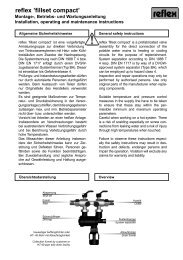
eflex ’fillset’<br />
Montage-, Betriebs- und Wartungsanleitung<br />
Installation, operating and maintenance instructions<br />
Allgemeine Sicherheitshinweise<br />
<strong>reflex</strong> ’fillset’ ist eine vorgefertigte<br />
Armaturengruppe zur direkten Verbindung<br />
von Trinkwassersytemen mit Heiz- oder Kühlkreisläufen<br />
zum Zwecke der Nachspeisung.<br />
Die Systemtrennung nach DIN 1988 T 4 bzw.<br />
DIN EN 1717 erfolgt durch einen DVGW-zugelassenen<br />
Systemtrenner (Typ BA). Dieser ist<br />
einsetzbar bis Gefahrenklasse 4. Die Kontrolle<br />
der Nachspeisemenge nach VDI 2035 wird<br />
über einen Wasserzähler realisiert.<br />
Prüfungs- und Instandsetzungsarbeiten dürfen<br />
nur durch autorisierte Personen durchgeführt<br />
werden. Beim Austausch von Teilen dürfen<br />
nur Originalteile des Herstellers verwendet<br />
werden.<br />
Es sind geeignete Maßnahmen zur Temperatur-<br />
und Druckabsicherung in der Versorgungsanlage<br />
zu treffen, damit die angegebenen<br />
zulässigen max. und min. Betriebsparameter<br />
nicht über- bzw. unterschritten werden.<br />
Vorsicht bei Arbeiten an einer heißen Anlage.<br />
Insbesondere an Verschraubungen besteht<br />
bei austretendem Wasser Verbrühungsgefahr<br />
und bei Berührung Verletzungsgefahr durch<br />
hohe Temperaturen.<br />
Das Missachten dieser Anleitung, insbesondere<br />
der Sicherheitshinweise, kann zu Zerstörung<br />
und Defekten führen, Personen gefährden<br />
sowie die Funktion beeinträchtigen.<br />
Bei Zuwiderhandlung sind jegliche Ansprüche<br />
auf Gewährleistung und Haftung ausgeschlossen.<br />
General safety instructions<br />
<strong>reflex</strong> ’fillset’ is a prefabricated valve assembly<br />
for the direct connection of potable water<br />
systems to heating or cooling circuits for the<br />
purpose of replenishment. System separation<br />
according to DIN 1988 T 4 resp. DIN EN 1717<br />
is by way of a DVGW-approved system separator<br />
(Type BA), which can be employed up<br />
to hazard class 4. The replenishment amount<br />
according to DIN 4751 T 2 is controlled by way<br />
of a water meter.<br />
Inspection and repair operations may only be<br />
performed by authorised persons. Use only<br />
original parts of the manufacturer when replacing<br />
components.<br />
Suitable temperature and pressure control<br />
measures in the supply line have to be taken<br />
to ensure that these stay within the permissible<br />
minimum and maximum operating<br />
parameters.<br />
Careful when working on a hot system. There<br />
is a risk of scalding especially on screw connections<br />
from leaking water and a risk of injury<br />
through high temperatures when touched.<br />
Failure to observe these instructions especially<br />
the safety instructions may result in destruction<br />
and defects, endanger persons and<br />
impair the operation. Violation will exclude any<br />
claims for warranty and liability.<br />
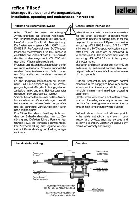
Übersichtsdarstellung<br />
Overview<br />
Absperrung<br />
Shut-off<br />
Eintritt<br />
Inlet<br />
Schmutzfänger<br />
Dirt trap<br />
Systemtrenner<br />
System separator<br />
Wasserzähler<br />
Water meter<br />
Austritt<br />
Outlet<br />
Wandhalterung<br />
Wall bracket<br />
bauseitiger Auffangtrichter oder<br />
HT- 40-Rohr mit Ablaufmöglichkeit<br />
Collection funnel by customer or<br />
HT-40-pipe with drain facility<br />
Ablauftrichter<br />
Drain funnel
eflex ’fillset’<br />
<br />
Lieferumfang<br />
1 Karton mit folgendem Inhalt:<br />
• <strong>reflex</strong> ’fillset’<br />
• Ablauftrichter<br />
• Montage-, Betriebs- und Wartungsanleitungen<br />
für ’fillset’<br />
und Systemtrenner<br />
Scope of delivery<br />
1 cardboard box with the following content:<br />
• <strong>reflex</strong> ’fillset’<br />
• drain tunnel<br />
• Assembly, operating and maintenance<br />
instructions for ’fillset’<br />
and system separator<br />
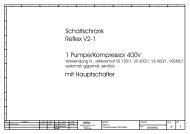
Technische Daten<br />
<strong>reflex</strong> ’fillset’ als Zubehör für den direkten<br />
Anschluss der Nachspeisung an ein<br />
Trinkwassernetz mit DVGW-geprüftem<br />
Systemtrenner Typ BA. Das ’fillset’ wird in<br />
den Varianten mit Standardwasserzähler<br />
oder Kontaktwasserzähler geliefert.<br />
zul. Betriebsüberdruck: 10 bar<br />
zul. Betriebstemperatur: 0 - 60 °C<br />
Mindestdifferenzdruck zur Öffnung<br />
des Systemtrenners: 0,8 bar<br />
Technical data<br />
<strong>reflex</strong> ’fillset’ as accessory for the direct connection<br />
of the make-up device to a potable<br />
water system with DVGW-tested system<br />
separator of type BA. The ’fillset’ is supplied<br />
in the version with standard water meter or<br />
contact water meter.<br />
Perm. operating pressure: 10 bar<br />
Perm. operating temp.: 0 - 60 °C<br />
Min. differential press. for opening<br />
the system separator: 0.8 bar<br />
Durchflusskennwert k VS<br />
- als einzelne Baugruppe: 0,8 m³/h<br />
- in Verbindung mit:<br />
’magcontrol’, ’variomat’,<br />
’<strong>reflex</strong>omat’ oder ’servitec’ 0,7 m³/h<br />
Flow characteristic k VS<br />
- as individual assembly: 0.8 m³/h<br />
- in connection with:<br />
’magcontrol’, ’variomat’,<br />
’<strong>reflex</strong>omat’ or ’servitec’ 0.7 m³/h<br />
Anschlüsse Eintritt:<br />
Austritt:<br />
R ½<br />
R ½<br />
Connections Inlet:<br />
Outlet:<br />
R ½<br />
R ½<br />
Einbaulage:<br />
horizontal<br />
Länge: 293 mm<br />
Leergewicht: 1,7 kg<br />
Installation position: horizontal<br />
Length: 293 mm<br />
Net weight: 1.7 kg<br />
Elektrotechnische Angaben des<br />
Kontaktwasserzählers:<br />
Bauart:<br />
Reedkontakt<br />
max. Schaltleistung: 4 W DC<br />
Impulsfolge:<br />
1 Kontakt/10 l<br />
Anschlusskabel:<br />
2 x 0,14 mm²,<br />
1,5 m lang<br />
Electrical details of the<br />
contact water meter:<br />
Type:<br />
max. switching power:<br />
Impulse sequence:<br />
Connection cable:<br />
Reed contact<br />
4 W DC<br />
1 contact/10 l<br />
2 x 0.14 mm²,<br />
1.5 m long<br />
Montage<br />
Installation<br />
Die Wandhalterung des ’fillset’ ist horizontal<br />
an der Wand zu montieren.<br />
Mount the wall bracket of the ’fillset’ horizontally<br />
to the wall.
eflex ’fillset’<br />
Die Nachspeiseleitung ist so in das<br />
System einzubinden, dass eine<br />
Druckabsicherung gegenüber zu hohem<br />
Trinkwassernetzdruck durch das anlagenseitige<br />
Sicherheitsventil gegeben ist.<br />
Ansonsten ist in die Nachspeiseleitung ein<br />
Druckminderer mit Sicherheitsventil einzubauen.<br />
Am Ablauftrichter betriebsbedingt<br />
austretendes Sperrwasser muss unterhalb<br />
des Systemtrenners bauseits abgeführt<br />
werden. Nach dem Einbau des ’fillset’<br />
ist die Dichtheit sowie die Funktion des<br />
Systemtrenners zu überprüfen (→ S. 4).<br />
Handnachspeisung<br />
Wird ’fillset’ zur Handnachspeisung bzw.<br />
zum Füllen der Anlage eingesetzt, ist der<br />
Absperrung je nach Bedarf manuell zu öffnen<br />
oder zu schließen. Der Anlagendruck<br />
ist am bauseitigen Manometer zu überwachen.<br />
Automatische Nachspeisung<br />
Wird das ’fillset’ vor automatische Nachspeisungen<br />
wie ’magcontrol’, ’variomat’ oder<br />
’servitec’ geschaltet, so ist die Absperrung<br />
im Betrieb ständig geöffnet.<br />
Bei ’fillset’ mit Kontaktwasserzähler wird<br />
dieser mit der Gebäudeleitttechnik bzw.<br />
<strong>reflex</strong> ’magcontrol’, ’servitec’, ’variomat’,<br />
’<strong>reflex</strong>omat’ oder ’gigamat’ verkabelt<br />
(→ entsprechende Bedienungsanleitung).<br />
Die Auswertung der Nachspeisemenge<br />
erfolgt dann über die entsprechende<br />
Steuerung.<br />
’fillset’ bei Handnachspeisung<br />
’fillset’ with manual replenishment<br />
Connect the replenishment line to the<br />
system to ensure that high potable water<br />
system pressure is prevented by means of<br />
the equipment safety valve. Otherwise a<br />
pressure reducer with safety valve must be<br />
installed in the replenishment line. Leakage<br />
water issuing from the drain funnel during<br />
operation must be discharged by the customer<br />
below the system separator. After the<br />
installation of the ’fillset’, check for leaks<br />
and the operation of the system separator<br />
(→ p. 4).<br />
Manual replenishment<br />
If ’fillset’ is employed for manual replenishment<br />
or for filling the system, manually open<br />
or close the shut-off as required. Check the<br />
system pressure on the pressure gauge<br />
provided by the customer.<br />
Automatic water make-up<br />
If the ’fillset’ is installed in front of the automatic<br />
water make-up units such as ’magcontrol’,<br />
’variomat’ or ’servitec’, the shut-off<br />
is constantly open in operation.<br />
In the case of ’fillset’ with contact water<br />
meter, the unit is connected with the building<br />
control instrumentation or <strong>reflex</strong> ’magcontrol’,<br />
’servitec’, ’variomat’, ’<strong>reflex</strong>omat’ or<br />
’gigamat’ (→ applicable operating instructions).<br />
The replenishment amount is then<br />
evaluated by the appropriate control.<br />
’fillset’ bei automatischer Nachspeisung<br />
’fillset’ with automatic water make-up<br />
’<strong>reflex</strong>’<br />
bauseits<br />
by customer<br />
’<strong>reflex</strong>’<br />
Einbindung<br />
in Kreislauf<br />
nähe MAG<br />
Connected to<br />
circuit near<br />
expansion vessel<br />
<strong>reflex</strong> ’fillset’<br />
Füllanschluß<br />
Filling connection<br />
Bei Einsatz von ’variomat’, ’<strong>reflex</strong>omat’ oder ’servitec’ Stationen wird analog<br />
verfahren. Die Nachspeiseleitung mit ’fillset’ ist dann nicht direkt in das System<br />
einzubinden, sondern an den gekennzeichneten Stutzen.<br />
Proceed in like manner when using ’variomat’, ’<strong>reflex</strong>omat’ or ’servitec’ stations.<br />
In such cases, do not directly connect the replenishment line to the system but<br />
to the marked spigot.<br />
<strong>reflex</strong> ’fillset’<br />
<strong>reflex</strong> ’magcontrol’<br />
Füllanschluß<br />
Filling connection
eflex ’fillset’<br />
<br />
Inbetriebnahme / Wartung<br />
Inbetriebnahme- und Wartungsarbeiten<br />
dürfen nur von Fachkundigen ausgeführt<br />
werden.<br />
Wartung Systemtrenner<br />
Für den Systemtrenner besteht nach DIN<br />
EN 1717 die Pflicht zur jährlichen Wartung.<br />
Die erstmalige Überprüfung erfolgt nach<br />
dem ersten Betriebsjahr, dann periodisch,<br />
spätesten aber nach einem Jahr.<br />
Die vorhandenen Anschlüsse für Kugelhähne<br />
ermöglichen mit dem entsprechenden<br />
Druckmessgerät eine Funktionsprüfung<br />
der Armatur.<br />
Reinigung von Schmutzfänger und<br />
BA-Patrone<br />
Sperren Sie mit Hilfe der ein- und ausgangsseitigen<br />
Absperrungen vor und<br />
nach des <strong>reflex</strong> ’fillset’ die System- und<br />
Trinkwasserleitung ab und machen Sie die<br />
Armatur drucklos.<br />
Schrauben Sie mit dem Wartungsschlüssel<br />
(SW 27) den Verschluss der BA-Patrone ab<br />
und entnehmen Sie die Patrone.<br />
Lösen Sie dann die beiden Verschraubungen<br />
oberhalb des Systemtrenners. Ziehen Sie<br />
den Schmutzfänger aus der eingangsseitigen<br />
Verschraubung nach oben heraus.<br />
Start-up / Maintenance<br />
Start-up and maintenance operations may<br />
only be performed by qualified personnel.<br />
Maintenance system separator<br />
The European Standard EN 1717 prescribes<br />
maintenance of the system separator type<br />
BA on an annual basis. The initial testing<br />
takes place after the first year of service,<br />
then periodically, but after one year at the<br />
latest.<br />
The connections for ball valves allow a functionality<br />
test of the device to be carried out<br />
with an adequate pressure gauge.<br />
Cleaning of dirt trap and BA-cartridge<br />
Isolate the system and the potable water<br />
mains by means of the shut-off valves<br />
upstream and downstream of <strong>reflex</strong> ’fillset’<br />
and unpressurize the device.<br />
Unscrew the top of the BA cartridge by using<br />
the maintenance key (SW 27) and remove<br />
the cartridge.<br />
Unscrew the two threaded connections<br />
above the system separator. Extract the dirt<br />
trap upwards out of the threaded connection<br />
on the side of the ’fillset’.<br />
SI0643A / 01 - 07<br />
Technische Änderungen vorbehalten / Subject to technical modification<br />
Reinigen Sie die entnommenen Bauteile<br />
unter klarem fließendem Wasser.<br />
Nach dem anschließenden Zusammenbau<br />
öffnen Sie anschließend die beiden<br />
Absperrungen.<br />
Reflex Winkelmann GmbH & Co. KG<br />
Gersteinstrasse 19<br />
59227 Ahlen<br />
Germany<br />
Telefon: +49 23 82 / 70 69 - 0<br />
Telefax: +49 23 82 / 70 69 - 588<br />
www.<strong>reflex</strong>.de<br />
Clean the removed parts with clear, running<br />
water.<br />
After the following assembly open both<br />
shut-off devices.