CombiTacline - Multi-Contact
CombiTacline - Multi-Contact
CombiTacline - Multi-Contact

Sie wollen auch ein ePaper? Erhöhen Sie die Reichweite Ihrer Titel.
YUMPU macht aus Druck-PDFs automatisch weboptimierte ePaper, die Google liebt.
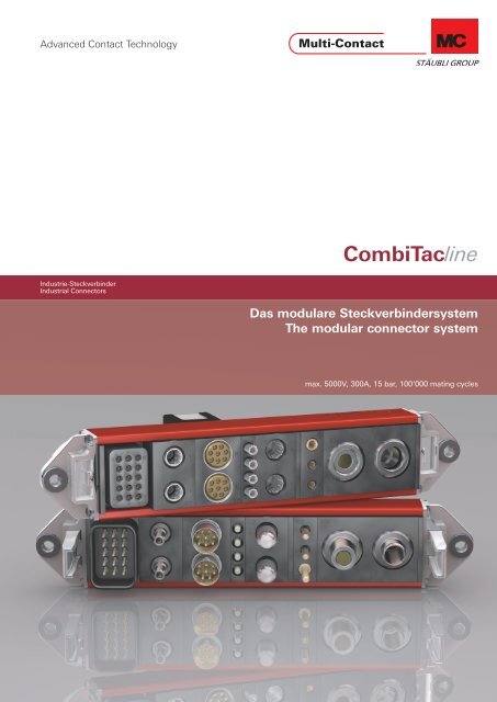
Advanced <strong>Contact</strong> Technology<br />
Industrie-Steckverbinder<br />
Industrial Connectors<br />
<strong>CombiTacline</strong><br />
Das modulare Steckverbindersystem<br />
The modular connector system<br />
max. 5000V, 300A, 15 bar, 100‘000 mating cycles<br />
1
Advanced <strong>Contact</strong> Technology<br />
MC Kontaktlamellen technik:<br />
Grenzenlose Möglichkeiten<br />
Kontaktlamellen sind speziell geformte, widerstandsfähige<br />
Geometrien aus Kupferlegierung, je nach Anwendung versilbert<br />
oder vergoldet und in einen Einstich schwimmend montiert.<br />
Der konstante Federdruck der Lamelle sorgt für eine permanente<br />
Kontaktierung mit der Kontakt oberfl äche und daraus<br />
resultiert ein geringer und konstanter Durchgangswiderstand.<br />
Die Kontaktlamellentechnik ermöglicht uns, eine Vielzahl von<br />
Lösungen anzubieten und selbst härteste Bedingungen zu erfüllen,<br />
sowohl elektrisch (bis zu mehreren kA), thermisch (bis<br />
zu 350°C) als auch mechanisch, mit Kontaktbeständigkeit bis<br />
zu 1 Million Steckzyklen.<br />
Wir sind auf die Entwicklung und Fertigung kundenspezifi scher<br />
Lösungen spezialisiert.<br />
MC <strong>Multi</strong>lam Technology:<br />
unlimited possibilities<br />
<strong>Multi</strong>lams are specially formed, resilient strips of copper alloy<br />
which are silver or gold-plated according to their application<br />
and are fl oat mounted in a groove. By its constant spring pressure<br />
the <strong>Multi</strong>lam maintains continuous contact with the contact<br />
surface, resulting in a low and constant contact resistance.<br />
<strong>Multi</strong>lam technology allows us to meet a very broad range of<br />
requirements and to fi nd solutions to the most severe constraints,<br />
including electrical (up to several kA), thermal (up to<br />
350°C) and mechanical, with contact durability of up to 1 million<br />
mating cycles.<br />
We are specialised in the design of custom solutions.<br />
Die richtige Technologie für höchste Anforderungen.<br />
The right technology for the strictest requirements.<br />
2 www.multi-contact.com
Advanced <strong>Contact</strong> Technology<br />
Vorteile der<br />
Kontaktlamellentechnik<br />
■ Minimaler Spannungsabfall<br />
■ Hohe Stromtragfähigkeit<br />
■ Minimaler Energieverlust<br />
■ Minimaler Durchgangswiderstand<br />
■ Kontakte mit hoher Lebensdauer bis zu 1 Million Steckzyklen<br />
■ Betriebstemperaturen bis 350°C, kurzzeitig sind höhere Temperaturen<br />
möglich<br />
■ Unempfi ndlich gegenüber Ölen<br />
■ Hohe Schlag-, Stoss- und Rüttel festigkeit<br />
■ Geringe Wartungskosten<br />
■ Runde, fl ache und sphärische Geo metrien<br />
■ Sehr gute Korrosionsbeständigkeit<br />
Advantages of<br />
<strong>Multi</strong>lam Technology<br />
■ Minimal voltage drop<br />
■ High current-carrying capacity<br />
■ Minimal power loss<br />
■ Minimal contact resistance<br />
■ High durability contacts withstand up to 1 million mating cycles<br />
■ Operating temperatures up to 350°C, higher temperatures<br />
permitted for short periods<br />
■ Good resistance to oils<br />
■ High resistance to vibration, shock and impact<br />
■ Low maintenance costs<br />
■ Round, fl at or spherical types<br />
■ Very good corrosion resistance<br />
Auszug aus dem Katalog <strong>Multi</strong>lamTechnology Extract from catalogue <strong>Multi</strong>lamTechnology<br />
Lamellensteg<br />
<strong>Multi</strong>lam louver<br />
� �1 / � �2 = Engewiderstand<br />
� � = Innenwiderstand des Lamellensteges<br />
� �1 / � �2 = Fremdschichtwiderstand<br />
� = Nennstrom<br />
Kontaktteil<br />
<strong>Contact</strong> part<br />
A<br />
Kontaktteil<br />
<strong>Contact</strong> part<br />
B<br />
www.multi-contact.com 3<br />
�<br />
� �1<br />
� �<br />
� �1<br />
� �2<br />
� �1 / � �2 = Constriction resistance<br />
� � = Internal resistance of louver<br />
� �1 / � �2 = Film resistance<br />
� = Nominal current<br />
� �2<br />
�
Advanced <strong>Contact</strong> Technology<br />
8 – 9<br />
10 – 16<br />
18 – 19<br />
20 – 21<br />
22 – 23<br />
24 – 27<br />
28 – 29<br />
30 – 31<br />
Inhalt Content<br />
Einführung Introduction<br />
Ø 12mm<br />
Leistungsmodul<br />
bis 300A, 1000V<br />
Ø 8mm<br />
Leistungsmodul<br />
bis 150A, 1000V<br />
Details für siehe Seite 95<br />
Ø 6mm, Ø 8mm<br />
Leistungsmodul<br />
bis 120A, 150A, 1000V<br />
Details für siehe Seite 95<br />
Ø 6mm<br />
Leistungsmodul<br />
bis 120A, 1000V<br />
Details für siehe Seite 95<br />
Ø 3mm<br />
Leistungsmodul<br />
bis 40A, 1000V<br />
Details für siehe Seite 95<br />
Ø 3mm<br />
Hochspannungsmodul<br />
bis 5kV, 32A<br />
Ø 1,5mm<br />
Signalmodul<br />
bis 19A, 600V<br />
Details für siehe Seite 95<br />
Ø 12mm<br />
Power unit<br />
up to 300A, 1000V<br />
Ø 8mm<br />
Power unit<br />
up to 150A, 1000V<br />
Details for see page 95<br />
Ø 6mm, Ø 8mm<br />
Power unit<br />
up to 120A, 150A, 1000V<br />
Details for see page 95<br />
Ø 6mm<br />
Power unit<br />
up to 120A, 1000V<br />
Details for see page 95<br />
Ø 3mm<br />
Power unit<br />
up to 40A, 1000V<br />
Details for see page 95<br />
Ø 3mm<br />
High voltage unit<br />
up to 5kV, 32A<br />
Ø 1,5mm<br />
Signal unit<br />
up to 19A, 600V<br />
Details for see page 95<br />
4 www.multi-contact.com
Advanced <strong>Contact</strong> Technology<br />
Ø 1mm<br />
Signalmodul<br />
bis 12A, 300V<br />
Details für siehe Seite 95<br />
Ø 0,6mm<br />
Signalmodul<br />
bis 6A, 150V<br />
Koaxialmodul<br />
RG58/RG59<br />
Datenübertragungsmodul<br />
CAT6 Ethernet IEEE802.3, Profi bus,<br />
Profi net, Interbus, CAN-BUS<br />
RJ45 Datenübertragungsmodul<br />
CAT5 Ethernet IEEE802.3<br />
Lichtwellenleitermodul POF<br />
(Polymere Optische Faser)<br />
Lichtwellenleitermodul GOF<br />
(Glasfaser)<br />
Ø 1mm<br />
Signal unit<br />
35 –<br />
up to 12A, 300V<br />
32<br />
Details for see page 95<br />
Ø 0,6mm<br />
Signal unit<br />
up to 6A, 150V<br />
Coaxial unit<br />
RG58/RG59<br />
Data transfer unit<br />
CAT6 Ethernet, IEEE802.3, Profi bus,<br />
Profi net, Interbus, CAN-BUS<br />
RJ45 Data Transfer Unit<br />
CAT5 Ethernet IEEE802.3<br />
Optical fi bres unit POF<br />
(Plastic optical fi ber)<br />
Optical fi bres unit GOF<br />
(Glass optical fi bre)<br />
Thermopaarmodul Thermocouple unit<br />
Pneumatik- und Flüssigkeitsmodule<br />
Druckluft – Vakuummodul<br />
Kühlfl üssigkeitsmodul<br />
15 bar<br />
Pneumatic and fl uid units<br />
www.multi-contact.com 5<br />
36 – 37<br />
38 – 39<br />
40 – 43<br />
44 – 45<br />
46 – 47<br />
48 – 51<br />
63<br />
Compressed air – vacuum unit<br />
–<br />
Coolant unit<br />
15 bar 52
Advanced <strong>Contact</strong> Technology<br />
64 – 67<br />
68 – 80<br />
81 – 83<br />
84 – 103<br />
info<br />
Einzelteile zu CombiTac-Rahmen<br />
Berechnung der Einbaumasse<br />
Plattenmontage<br />
DIN-Gehäuse für CombiTac<br />
Kodierung<br />
Ermittlung der Gehäusegrösse<br />
Distanzstücke<br />
Bestellangaben für DIN-Gehäuse<br />
Crimpzangen<br />
Montagewerkzeuge<br />
Anhang<br />
Derating Diagramme<br />
Technische Hinweise<br />
Index<br />
Single parts for CombiTac frames<br />
Calculation of installation dimensions<br />
Panel mounted<br />
DIN housings for CombiTac<br />
Coding<br />
Calculation of housing size<br />
Spacers<br />
Ordering information for DIN housings<br />
Crimping pliers<br />
Assembly tools<br />
Appendix<br />
Derating diagrams<br />
Technical information<br />
Index<br />
6 www.multi-contact.com
Advanced <strong>Contact</strong> Technology<br />
Allgemeine Angaben<br />
Änderungen / Vorbehalte<br />
Alle Daten, Abbildungen und Zeichnungen in diesem Katalog<br />
sind das Resultat sorgfältiger Prüfungen. Sie entsprechen dem<br />
Stand unserer Erfahrungen, Irrtum vorbehalten. Ebenfalls vorbehalten<br />
sind Änderungen aus konstruktions- bzw. sicherheitstechnischen<br />
Gründen. Es ist deshalb ratsam, bei Konstruktionen,<br />
in die unsere Bauteile einfl iessen, nicht alleine die Katalogdaten<br />
heranzuziehen, sondern mit uns Rücksprache zu nehmen, um<br />
sicherzustellen, dass die neuesten Daten zur Anwendung kommen.<br />
Wir beraten Sie gerne.<br />
Urheberrecht<br />
Die Weiterverwendung dieser Katalogunterlagen in jedweder<br />
Form ohne unsere vorherige schriftliche Genehmigung ist nicht<br />
gestattet.<br />
RoHSready<br />
Alle CombiTac Teile erfüllen die Richtlinie 2011/65/EU zur Beschränkung<br />
der Verwendung bestimmter gefährlicher Stoffe in<br />
Elektro- und Elektronikgeräten.<br />
Symbole<br />
Ich bin eine Montageanleitung.<br />
Man sollte mich unbedingt le-<br />
sen, bevor man das Produkt ver-<br />
wendet! Ich beinhalte wertvolle<br />
Hinweise zur korrekten Montage<br />
und zum richtigen Einsatz des<br />
Produktes. Im Moment ist die<br />
Schrift zwar ein bischen klein,<br />
aber später geht das dann ganz<br />
gut zu lesen, da die MA dann<br />
RZ<br />
MA<br />
Zu diesem Produkt gibt es Zubehör oder spezielle<br />
Werkzeuge<br />
Bitte lesen Sie vor Benutzung den zugehörigen<br />
Beilegzettel RZ000<br />
Zu diesem Produkt ist eine Montageanleitung<br />
MA000 vorhanden<br />
Oberfl äche Ag<br />
Oberfl äche Au<br />
Abkürzungen<br />
S = Schraubanschluss<br />
PCB = Schwalllötanschluss<br />
C = Crimpanschluss<br />
L = Lötanschluss<br />
AWG = American Wire Gauge<br />
(US Drahtdurchmesser)<br />
Gehäuse<br />
TG = Tüllengehäuse<br />
KG = Kupplungsgehäuse<br />
AG = Anbaugehäuse<br />
SG = Sockelgehäuse<br />
-S = Kabeleingang seitlich<br />
-G = Kabeleingang gerade<br />
-PW = Schutzwand<br />
-D = mit Deckel<br />
-PS = Parkstation<br />
ZV = Zentrale Verriegelung<br />
SD-...L/FSCH = Schutzdeckel aus Kunststoff mit Fangschnur<br />
für Metall Gehäuse IP65<br />
General information<br />
Changes / Provisos<br />
All data, illustrations and drawings in the catalogue have been<br />
carefully checked. They are in accordance with our experience<br />
to date, but no responsibility can be accepted for errors.<br />
We also reserve the right to make modifi cations for design and<br />
safety reasons. When designing equipment incorporating our<br />
components, it is therefore advisable not to rely solely on the<br />
data in the catalogue but to consult us to make sure this information<br />
is up to date. We shall be pleased to advise you.<br />
Copyright<br />
The use of this catalogue for any other purpose, in whatever<br />
form, without our prior written consent is not permitted.<br />
RoHSready<br />
All CombiTac parts comply with Directive 2011/65/EC on the<br />
restriction of the use of certain hazardous substances in electrical<br />
and electronic equipment.<br />
Symbols<br />
www.multi-contact.com 7<br />
Ich bin eine Montageanleitung.<br />
Man sollte mich unbedingt le-<br />
sen, bevor man das Produkt ver-<br />
wendet! Ich beinhalte wertvolle<br />
Hinweise zur korrekten Montage<br />
und zum richtigen Einsatz des<br />
Produktes. Im Moment ist die<br />
Schrift zwar ein bischen klein,<br />
aber später geht das dann ganz<br />
gut zu lesen, da die MA dann<br />
RZ<br />
MA<br />
Accessories or special tools exist for this product<br />
Before use, please read the enclosed RZ Sheet<br />
RZ000<br />
The assembly instructions MA000 is available for<br />
this product<br />
Surface Ag<br />
Surface Au<br />
Abbreviations<br />
S = Screw termination<br />
PCB = Flow soldered termination<br />
C = Crimp termination<br />
L = Soldering<br />
AWG = American Wire Gauge<br />
Housing<br />
TG = Sleeve housing<br />
KG = Coupler hood<br />
AG = Surface mount housing<br />
SG = Pedestal mount housing<br />
-S = Cable inlet, side<br />
-G = Cable inlet, straight<br />
-PW = Protective wall<br />
-D = with lid<br />
-PS = Park station<br />
ZV = Central locking<br />
SD-...L/FSCH = Plastic protective cover with<br />
lanyard for metal housing IP65
Advanced <strong>Contact</strong> Technology<br />
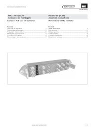
MC CombiTac<br />
das modulare Steckverbindersystem<br />
DIN-Tüllengehäuse<br />
6 verschiedenen Grössen<br />
Schienen<br />
Im Lieferumfang enthalten<br />
Separate Bestellung möglich<br />
Endteile in 2 Ausführungen<br />
■ Gehäusemontage<br />
■ Plattenmontage<br />
Im Lieferumfang enthalten<br />
Separate Bestellung möglich<br />
Auslieferungsstatus des CombiTac<br />
■ Kontaktträger auf Schienen montiert<br />
■ mit Endteilen montiert<br />
■ Kontakte separat<br />
■ Druckluft- und Kühlfl üssigkeits-Steckverbinder<br />
werden in die Träger montiert<br />
■ Auf Wunsch werden PCB Kontakte<br />
montiert<br />
Mögliche Verbindungen:<br />
■ Elektrisch<br />
■ Thermopaar-Druckkontakte<br />
■ Koaxial<br />
■ Lichtwellenleiter<br />
■ Druckluft<br />
■ Flüssigkeit<br />
■ Elektrisch + PE<br />
■ Datentransfer<br />
Fertig konfektionierter CombiTac-Steckverbinder<br />
mit Anschlussleitungen<br />
Auf Anfrage<br />
DIN-Anbaugehäuse und Sockelgehäuse<br />
6 verschiedenen Grössen<br />
Steckzyklen:<br />
CombiTac als Plattenmontage: bis 100‘000<br />
CombiTac in Gehäuse: bis 5‘000<br />
MC CombiTac<br />
the modular connector system<br />
DIN coupler hoods<br />
6 different sizes<br />
Rails<br />
Included in delivery<br />
May be ordered separately<br />
End pieces in 2 versions<br />
■ Housing assembly<br />
■ Plate mounting<br />
Included in delivery<br />
May be ordered separately<br />
Delivery status of the CombiTac<br />
■ <strong>Contact</strong> carriers mounted on rails<br />
■ Assembled with end pieces<br />
■ <strong>Contact</strong>s separately<br />
■ Gas and fl uid couplings will be mounted<br />
in the carriers<br />
■ PCB contacts will be mounted on request<br />
Possible connections:<br />
■ Electric<br />
■ Thermocouple pressure contacts<br />
■ Coaxial<br />
■ Optical fi bre<br />
■ Compressed air<br />
■ Liquid<br />
■ Electric + PE<br />
■ Data transfer<br />
Fully assembled CombiTac connector<br />
with connecting lines<br />
On request<br />
DIN surface and pedestal mount<br />
housing<br />
6 different sizes<br />
Mating cycles:<br />
CombiTac as panel mounted: up to 100‘000<br />
CombiTac in housing: up to 5‘000<br />
8 www.multi-contact.com
Advanced <strong>Contact</strong> Technology<br />
Kombinieren Sie!<br />
Die bequemste Methode, einen eigenen Steckverbinder zusammenzustellen<br />
fi nden Sie auf unserer Homepage:<br />
www.multi-contact.com<br />
CombiTac Confi gurator<br />
Empfehlung: Am besten Sie benutzen den Confi gurator,<br />
zusammen mit diesem Katalog und den Montageanleitungen<br />
MA213... (ebenfalls auf der Homepage zu fi nden).<br />
Für Bestellungen und Offerten<br />
For orders and offers<br />
Anzeige der gewählten Kombination<br />
Indication of the selected combination<br />
Auswahl der Kontaktträger<br />
Choice of contact carriers<br />
Auswahl der Kontakte<br />
Choice of contacts<br />
Vorschau und Stücklisten<br />
Preview and parts list<br />
CombiTac Confi gurator<br />
Spezialanfertigungen für individuelle Anforderungen sind auf<br />
Anfrage möglich.<br />
Please combine<br />
The simplest way to assemble a CombiTac is on our website:<br />
www.multi-contact.com<br />
CombiTac Confi gurator<br />
Recommendation: It is simplest to use the confi gurator, together<br />
with this catalogue and assembly instruction MA213...<br />
(also to be found on the website).<br />
Special designs for individual requirements are available on request.<br />
www.multi-contact.com 9
Advanced <strong>Contact</strong> Technology<br />
Ø 12mm<br />
Leistungsmodul bis 300A<br />
Kontaktträger CT-E12-1/...<br />
1-poliger Kontaktträger aus Kunststoff. Unterschiedliche Bauformen<br />
für Stifte und Buchsen.<br />
Arretierung der Kontakte mittels Sicherungsbügel CT-RC12.<br />
CT-E12-1/B<br />
CT-E12-1/S<br />
CT-RC12<br />
Typ<br />
Type<br />
Ich bin eine Montageanleitung.<br />
Man sollte mich unbedingt le-<br />
sen, bevor man das Produkt ver-<br />
wendet! Ich beinhalte wertvolle<br />
Hinweise zur korrekten Montage<br />
und zum richtigen Einsatz des<br />
Produktes. Im Moment ist die<br />
Schrift zwar ein bischen klein,<br />
aber später geht das dann ganz<br />
gut zu lesen, da die MA dann<br />
MA<br />
Montageanleitung MA213-01<br />
www.multi-contact.com<br />
<strong>Contact</strong> carriers CT-E12-1/...<br />
1-pole plastic contact carriers. Different designs for pins and<br />
sockets.<br />
The contacts are locked by means of a retaining clip CT-RC12.<br />
Technische Daten Technical data<br />
Polzahl Number of poles 1<br />
Für Kontaktdurchmesser For contact diameter 12mm<br />
Verschmutzungsgrad / Überspannungskat. Pollution degree / Overvoltage category 2 / CATII 3 / CATIII<br />
Bemessungsspannung, Crimpanschluss<br />
Schraubanschluss<br />
Rated voltage, Crimp termination<br />
Screw termination<br />
Schutzart (Buchsen- und Steckervorderteil) Degree of protection (Socket- and Plug front) IP2X<br />
Luft- und Kriechstrecken Clearances and creepage distance IEC 60664-1<br />
Grenztemperatur (IEC 61984), obere<br />
untere<br />
Bestell-Nr.<br />
Order No.<br />
Limiting temperature (IEC 61984), upper<br />
lower<br />
Ø 12mm<br />
Power unit up to 300A<br />
Beschreibung<br />
Description<br />
CT-E12-1/B 33.4082 Buchsenträger (Kennzeichnung „B“) / Socket carrier (Identifi cation „B“)<br />
CT-E12-1/S 33.4081 Stiftträger (Kennzeichnung „S“) / Pin carrier (Identifi cation „S“)<br />
CT-RC12 33.4083 Sicherungsbügel / Retaining clip<br />
Kontaktträgermaterial <strong>Contact</strong> carrier material PA<br />
10 www.multi-contact.com<br />
Ich bin eine Montageanleitung.<br />
Man sollte mich unbedingt le-<br />
sen, bevor man das Produkt ver-<br />
wendet! Ich beinhalte wertvolle<br />
Hinweise zur korrekten Montage<br />
und zum richtigen Einsatz des<br />
Produktes. Im Moment ist die<br />
Schrift zwar ein bischen klein,<br />
aber später geht das dann ganz<br />
gut zu lesen, da die MA dann<br />
MA<br />
1000V AC/DC IEC, 600V UL 800V AC/DC<br />
400V AC/DC<br />
+90°C<br />
-40°C<br />
Assembly instructions MA213-01<br />
www.multi-contact.com
Advanced <strong>Contact</strong> Technology<br />
Ø 12mm Kontakte mit Crimpanschluss<br />
Für Kontaktträger CT-E12-1/... Buchsen mit MC Kontaktlamelle<br />
ausgerüstet.<br />
Anschlussart:<br />
■ Crimpanschluss (C) für Cu-Leiter (Klasse 5 und 6)<br />
CT-BP12/...<br />
Typ<br />
Type<br />
CT-BP12/50 AG<br />
CT-SP12/50 IP2X AG<br />
CT-BP12/70 AG<br />
CT-SP12/70 IP2X AG<br />
CT-BP12/95 AG<br />
CT-SP12/95 IP2X AG<br />
Ich bin eine Montageanleitung.<br />
Man sollte mich unbedingt le-<br />
sen, bevor man das Produkt ver-<br />
wendet! Ich beinhalte wertvolle<br />
Hinweise zur korrekten Montage<br />
und zum richtigen Einsatz des<br />
Produktes. Im Moment ist die<br />
Schrift zwar ein bischen klein,<br />
aber später geht das dann ganz<br />
gut zu lesen, da die MA dann<br />
MA<br />
Bestell-Nr.<br />
Order No.<br />
33.0127<br />
33.0558<br />
33.0128<br />
33.0559<br />
33.0138<br />
33.0562<br />
Buchse<br />
Socket<br />
Montageanleitung MA213-01<br />
www.multi-contact.com<br />
CT-SP12/...<br />
1) Bemessungswerte beziehen sich auf wärme beständige Kupferleitungen<br />
gemäss DIN VDE 0298-4.<br />
×<br />
×<br />
×<br />
Stift<br />
Pin<br />
×<br />
×<br />
×<br />
Oberfl äche<br />
Surface<br />
Ø 12mm contacts with crimp termination<br />
For contact carriers CT-E12-1/... Sockets fi tted with MC<br />
<strong>Multi</strong>lam.<br />
Type of termination:<br />
■ Crimp termination (C) for Cu conductors (class 5 and 6)<br />
Leiterquerschnitt<br />
Conductor cross section<br />
1) Rated values refer to heat-resistant copper wires in accordance with<br />
DIN VDE 0298-4.<br />
www.multi-contact.com 11<br />
Ich bin eine Montageanleitung.<br />
Man sollte mich unbedingt le-<br />
sen, bevor man das Produkt ver-<br />
wendet! Ich beinhalte wertvolle<br />
Hinweise zur korrekten Montage<br />
und zum richtigen Einsatz des<br />
Produktes. Im Moment ist die<br />
Schrift zwar ein bischen klein,<br />
aber später geht das dann ganz<br />
gut zu lesen, da die MA dann<br />
MA<br />
Bemessungsstrom 1)<br />
Rated current 1)<br />
mm² AWG A<br />
50 1/0 200<br />
70 2/0 245<br />
95 3/0 300<br />
Technische Daten Technical data<br />
Nenn-Ø Buchse/Stift Nominal-Ø socket/pin 12mm<br />
Max. Schiebekraft pro Kontakt Max. sliding force per contact 32N<br />
Durchgangswiderstand <strong>Contact</strong> resistance < 25μΩ<br />
Steckzyklen Mating cycles 100‘000<br />
Anschlussart<br />
Type of termination<br />
Assembly instructions MA213-01<br />
www.multi-contact.com<br />
C<br />
C<br />
C
Advanced <strong>Contact</strong> Technology<br />
Ø 12mm Kontakte mit M10 Innengewinde<br />
Für Kontaktträger CT-E12-1/... Buchsen mit MC Kontaktlamelle<br />
ausgerüstet.<br />
Anschlussart:<br />
■ Schraubanschluss (S) über ein M10 Innengewinde mittels<br />
Kabelschuh für Cu-Leiter (Klasse 5 und 6)<br />
Hinweis:<br />
Kann aus Platzgründen nicht in einem Gehäuse eingesetzt werden.<br />
CT-B12/M10 AG CT-S12/M10 IP2X AG<br />
Typ<br />
Type<br />
Bestell-Nr.<br />
Order No.<br />
1) Abhängig von der Kabelschuhgrösse.<br />
Buchse<br />
Socket<br />
CT-B12/M10 AG 33.0139 ×<br />
Stift<br />
Pin<br />
CT-S12/M10 IP2X AG 33.0564 ×<br />
K-SCH50-10 3) 33001501 Kabelschuh<br />
Cable lug<br />
CT-K-SCH70-10 3) 33.4114<br />
CT-K-SCH95-10 3) 33.4115<br />
Kabelschuh<br />
Cable lug<br />
Kabelschuh<br />
Cable lug<br />
Oberfl äche<br />
Surface<br />
2) Bemessungswerte beziehen sich auf wärme beständige Kupferleitungen<br />
gemäss DIN VDE 0298-4.<br />
3) Kabelschuhe Cu/Sn nach DIN 46234.<br />
Ø 12mm contacts with M10 inside thread<br />
For contact carriers CT-E12-1/... Sockets fi tted with MC<br />
<strong>Multi</strong>lam.<br />
Type of termination:<br />
■ Screw termination (S) using an M10 inside thread by means<br />
of a cable lug for Cu conductors (class 5 and 6)<br />
Note:<br />
May not be fi tted in a housing for space reasons.<br />
Leiterquerschnitt<br />
Conductor cross section<br />
Bemessungsstrom 2)<br />
Rated current 2)<br />
mm² AWG A<br />
Anschlussart<br />
Type of termination<br />
1) Depending on cable lug size.<br />
2) Rated values refer to heat-resistant copper wires in accordance with DIN<br />
VDE 0298-4.<br />
3) Cable lugs Cu/Sn according to DIN 46234.<br />
12 www.multi-contact.com<br />
50<br />
70<br />
95<br />
50<br />
70<br />
95<br />
1/0<br />
2/0<br />
3/0<br />
1/0<br />
2/0<br />
3/0<br />
50 1/0<br />
70 2/0<br />
95 3/0<br />
Einzelteile (Im Lieferumfang von 33.0139 und 33.0564 enthalten) Individual parts (Supplied with 33.0139 and 33.0564)<br />
Pos.<br />
Typ<br />
Type<br />
Bestell-Nr.<br />
Order No.<br />
Bemerkungen<br />
Remarks<br />
1 ZYL-SHR-IN-6KT M10×20 ISO4762 BN610 11004669 Zylinder-Schraube / Cheese head screw M10x20<br />
2 F/M10 DIN6798A BN781 08.0706 Fächerscheibe / Serrated lock washer F/M10<br />
3 U/M10 AG 08.0306 U-Scheibe / Washer M10<br />
Technische Daten Technical data<br />
Nenn-Ø Buchse/Stift Nominal-Ø socket/pin 12mm<br />
Max. Schiebekraft pro Kontakt Max. sliding force per contact 32N<br />
Durchgangswiderstand <strong>Contact</strong> resistance 25μΩ<br />
Steckzyklen Mating cycles 100‘000<br />
200<br />
245<br />
300<br />
200<br />
245<br />
300<br />
S<br />
S
Advanced <strong>Contact</strong> Technology<br />
Auswahl spezieller DIN-Gehäuse für das<br />
CombiTac Ø 12mm Leistungsmodul<br />
Schritt 1: Wählen Sie die Anzahl der Ø 12mm Pole Ihres<br />
CombiTac Steckverbinders (z.B. 2 × Ø 12mm Pole)<br />
Schritt 2: Wählen Sie den Kabelaussendurchmesser<br />
(z.B. 17mm)<br />
Schritt 3: Wählen Sie die entsprechende Kabelverschraubung<br />
(z.B. Bestell-Nr. 33.4126 oder 33.4122)<br />
Schritt 4: Wählen Sie das passende DIN-Gehäuse (z.B.<br />
Grösse 3, Bestell-Nr. 33.1267)<br />
1) Ein Bohrloch mit Verschlusskappe schliessen (nicht im Lieferumfang enthalten).<br />
2) Auf Anfrage / Spezielles Gehäuse.<br />
Selection of special DIN-Housings for<br />
CombiTac Ø 12mm power unit<br />
Step 1: Select the number of Ø 12mm poles of your<br />
CombiTac connector (e.g. 2 × Ø 12mm poles)<br />
Step 2: Select the outer insulation diameter of your cable<br />
(e.g. 17mm)<br />
Step 3: Select the appropriate cable gland (e.g. order No.<br />
33.4126 or 33.4122)<br />
Step 4: Select a suitable DIN-housing (e.g. size 3, order No.<br />
33.1267)<br />
1 2 3 4<br />
Anzahl der Pole<br />
Number of poles<br />
1<br />
2<br />
(+ / -)<br />
(L1 / N)<br />
3<br />
(+ / - / PE)<br />
(L1 / N / PE)<br />
4<br />
(L1 / L2 / L3 / PE)<br />
(L1 / L2 / L3 / N)<br />
5<br />
(L1 / L2 / L3 / N / PE)<br />
Für Kabel-Ø<br />
For Ø cable<br />
Grösse<br />
Size<br />
Kabelverschraubung<br />
Cable gland<br />
Typ<br />
Type<br />
1) Close one gland opening with cap (not provided).<br />
2) Special housings available on request.<br />
Geeignetes Gehäuse<br />
Suitable housing<br />
www.multi-contact.com 13<br />
Bestell-Nr.<br />
Order No.<br />
Schlüsselweite max.<br />
Wrench size max.<br />
mm M mm<br />
14 – 17<br />
CT-K-VSH M32x14-17 MS 33.4123<br />
17 – 21 32 CT-K-VSH M32x17-21 MS 33.4124<br />
21 – 25 CT-K-VSH M32x21-25,5 MS 33.4125<br />
9,5 – 12,5<br />
CT-K-VSH M25x9,5-12,5 MS 33.4120 30<br />
10 – 17 25 CT-K-VSH M25x10-17 MS 33.4126 28<br />
16 – 20,5 CT-K-VSH M25x16-20,5 MS 33.4122 30<br />
17 – 21 CT-K-VSH M32x17-21 MS 33.4124<br />
32<br />
21 – 25 CT-K-VSH M32x21-25,5 MS 33.4125<br />
Grösse<br />
Size<br />
Typ<br />
Type<br />
Bestell-Nr.<br />
Order No.<br />
36 1 CT-TG1-G 33.1571<br />
3 CT-TG3-G/2×M25 33.1267<br />
36 4 CT-TG4-G/2×M32 33.1269<br />
10 – 17 25 CT-K-VSH M25x10-17 MS 33.4126 28 4 CT-TG4-G/3xM25 33.1268<br />
9,5 – 12,5<br />
CT-K-VSH M25x9,5-12,5 MS 33.4120 30<br />
10 – 17 25 CT-K-VSH M25x10-17 MS 33.4126 28<br />
16 – 20,5 CT-K-VSH M25x16-20,5 MS 33.4122 30<br />
17 – 21 CT-K-VSH M32x17-21 MS 33.4124<br />
32<br />
21 – 25 CT-K-VSH M32x21-25,5 MS 33.4125<br />
9,5 – 12,5<br />
CT-K-VSH M25x9,5-12,5 MS 33.4120 30<br />
10 – 17 25 CT-K-VSH M25x10-17 MS 33.4126 28<br />
16 – 20,5 CT-K-VSH M25x16-20,5 MS 33.4122 30<br />
17 – 21 CT-K-VSH M32x17-21 MS 33.4124<br />
32<br />
21 – 25 CT-K-VSH M32x21-25,5 MS 33.4125<br />
5<br />
CT-TG5-G/4xM25 33.1270<br />
1)<br />
36 6 CT-TG6-G/3xM32 33.1272<br />
5 CT-TG5-G/4xM25 33.1270<br />
36 6+ CT-TG6+ 2) 33.1386<br />
10 – 17 25 CT-K-VSH M25x10-17 MS 33.4126 28 6 CT-TG6-G/6xM25 1) 33.1271<br />
17 – 21 CT-K-VSH M32x17-21 MS 33.4124<br />
32<br />
21 – 25 CT-K-VSH M32x21-25,5 MS 33.4125<br />
36 6+ CT-TG6+ 2) 33.1386<br />
Position<br />
Kabelverschraubungen<br />
Position<br />
of cable glands
Advanced <strong>Contact</strong> Technology<br />
Kontaktträger CT-E8/6-PE<br />
1-poliger Kontaktträger aus elastischem Kunststoff. Kennzeichnung<br />
mit Erdungssymbol.<br />
CT-E8/6-PE<br />
Typ<br />
Type<br />
Ich bin eine Montageanleitung.<br />
Man sollte mich unbedingt le-<br />
sen, bevor man das Produkt ver-<br />
wendet! Ich beinhalte wertvolle<br />
Hinweise zur korrekten Montage<br />
und zum richtigen Einsatz des<br />
Produktes. Im Moment ist die<br />
Schrift zwar ein bischen klein,<br />
aber später geht das dann ganz<br />
gut zu lesen, da die MA dann<br />
MA<br />
Montageanleitung MA213-01<br />
www.multi-contact.com<br />
Bestell-Nr.<br />
Order No.<br />
CT-E8/6-PE 33.4008<br />
<strong>Contact</strong> carrier CT-E8/6-PE<br />
1-pole contact carrier made of resilient plastic. Marked with<br />
an earthing symbol.<br />
Technische Daten Technical data<br />
Polzahl Number of poles 1<br />
Für Kontaktdurchmesser For contact diameter 8mm<br />
Verschmutzungsgrad / Überspannungskat. Pollution degree / Overvoltage category 2 / CATII 3 / CATIII<br />
Bemessungsspannung, Crimpanschluss<br />
Schraubanschluss<br />
Rated voltage, Crimp termination<br />
Screw termination<br />
14 www.multi-contact.com<br />
Ich bin eine Montageanleitung.<br />
Man sollte mich unbedingt le-<br />
sen, bevor man das Produkt ver-<br />
wendet! Ich beinhalte wertvolle<br />
Hinweise zur korrekten Montage<br />
und zum richtigen Einsatz des<br />
Produktes. Im Moment ist die<br />
Schrift zwar ein bischen klein,<br />
aber später geht das dann ganz<br />
gut zu lesen, da die MA dann<br />
MA<br />
1000V AC/DC<br />
600V AC/DC<br />
Schutzart (Buchsen- und Steckervorderteil) Degree of protection (Socket- and Plug front) IP00<br />
Luft- und Kriechstrecken Clearances and creepage distance IEC 60664-1<br />
Grenztemperatur (IEC 61984), obere<br />
untere<br />
Limiting temperature (IEC 61984), upper<br />
lower<br />
+90°C<br />
-40°C<br />
Kontaktträgermaterial <strong>Contact</strong> carrier material EPTR<br />
Assembly instructions MA213-01<br />
www.multi-contact.com<br />
400V AC/DC<br />
300V AC/DC
Advanced <strong>Contact</strong> Technology<br />
Ø 8mm voreilende Kontakte<br />
mit Crimp anschluss<br />
Für Kontaktträger CT-E8/6-PE. Buchsen mit MC Kontaktlamelle<br />
ausgerüstet.<br />
Anschlussart:<br />
■ Crimpanschluss (C) für Cu-Leiter (Klasse 5 und 6)<br />
CT-BP8/...PE-L AG<br />
Typ<br />
Type<br />
Ich bin eine Montageanleitung.<br />
Man sollte mich unbedingt le-<br />
sen, bevor man das Produkt ver-<br />
wendet! Ich beinhalte wertvolle<br />
Hinweise zur korrekten Montage<br />
und zum richtigen Einsatz des<br />
Produktes. Im Moment ist die<br />
Schrift zwar ein bischen klein,<br />
aber später geht das dann ganz<br />
gut zu lesen, da die MA dann<br />
MA<br />
Bestell-Nr.<br />
Order No.<br />
CT-SP8/...PE-L AG<br />
Buchse<br />
Socket<br />
1) Bemessungswerte beziehen sich auf wärme beständige Kupferleitungen<br />
gemäss DIN VDE 0298-4.<br />
Montageanleitung MA213-01<br />
www.multi-contact.com<br />
Stift<br />
Pin<br />
Oberfl äche<br />
Surface<br />
Ø 8mm fi rst make contacts<br />
with crimp termination<br />
For contact carrier CT-E8/6-PE. Sockets fi tted with MC <strong>Multi</strong>lam.<br />
Type of termination:<br />
■ Crimp termination (C) for Cu conductors (class 5 and 6)<br />
Leiterquerschnitt<br />
Conductor cross section<br />
1) Rated values refer to heat-resistant copper wires in accordance with<br />
DIN VDE 0298-4.<br />
www.multi-contact.com 15<br />
Ich bin eine Montageanleitung.<br />
Man sollte mich unbedingt le-<br />
sen, bevor man das Produkt ver-<br />
wendet! Ich beinhalte wertvolle<br />
Hinweise zur korrekten Montage<br />
und zum richtigen Einsatz des<br />
Produktes. Im Moment ist die<br />
Schrift zwar ein bischen klein,<br />
aber später geht das dann ganz<br />
gut zu lesen, da die MA dann<br />
MA<br />
Bemessungsstrom 1)<br />
Rated current 1)<br />
mm² AWG A<br />
CT-BP8/25/PE-L AG 33.0205 × 25 4 130<br />
CT-SP8/25/PE-L AG 33.0705 × 25 4 130<br />
CT-BP8/35/PE-L AG 33.0206 × 35 2 160<br />
CT-SP8/35/PE-L AG 33.0706 × 35 2 160<br />
CT-BP8/50/PE-L AG 33.0207 × 50 1/0 200<br />
CT-SP8/50/PE-L AG 33.0707 × 50 1/0 200<br />
Technische Daten Technical data<br />
Nenn-Ø Buchse/Stift Nominal-Ø socket/pin 8mm<br />
Max. Schiebekraft pro Kontakt Max. sliding force per contact 11,5N<br />
Steckzyklen Mating cycles 100‘000<br />
Anschlussart<br />
Type of termination<br />
Assembly instructions MA213-01<br />
www.multi-contact.com<br />
C<br />
C<br />
C<br />
C<br />
C<br />
C
Advanced <strong>Contact</strong> Technology<br />
Ø 8mm Voreilende Kontakte mit<br />
M8 Aussengewinde<br />
Für Kontaktträger CT-E8/6-PE, voreilend. Buchsen mit MC<br />
Kontaktlamelle ausgerüstet.<br />
Anschlussart:<br />
■ Schraubanschluss (S) über ein M8 Aussengewinde mittels<br />
Kabelschuh für Cu-Leiter (Klasse 5 und 6)<br />
CT-B8/M8A/PE-L AG<br />
Typ<br />
Type<br />
CT-B8/M8A/PE-L AG<br />
CT-S8/M8A/PE-L AG<br />
Bestell-Nr.<br />
Order No.<br />
33.0208<br />
33.0708<br />
CT-K-SCH25-8 2) 33.4117<br />
CT-K-SCH35-8 2) 33.4116<br />
CT-S8/M8A/PE-L AG<br />
Buchse<br />
Socket<br />
Stift<br />
Pin<br />
Oberfl äche<br />
Surface<br />
1) Bemessungswerte beziehen sich auf wärme beständige Kupferleitungen<br />
gemäss DIN VDE 0298-4.<br />
2) Kabelschuhe Cu/Sn nach DIN 46234 (Klasse 5).<br />
3) Erdungskontakte mit M8 Aussengewinde benötigen zwingend eine Abtrennung<br />
mittels CT-DIP4/2 zum Ø 12mm Kontakt.<br />
×<br />
Kabelschuh<br />
Cable lug<br />
Kabelschuh<br />
Cable lug<br />
K-SCH50-8 2) 31002862 Kabelschuh<br />
Cable lug<br />
CT-DIP4/2 3) 33.4085<br />
×<br />
Distanzstück<br />
Spacer<br />
Ø 8mm fi rst make contacts with<br />
M8 outside thread<br />
For contact carrier CT-E8/6-PE, fi rst make. Sockets fi tted with<br />
MC <strong>Multi</strong>lam.<br />
Type of termination:<br />
■ Screw termination (S) with an M8 male thread by means of a<br />
cable lug for Cu conductors (class 5 and 6)<br />
Leiterquerschnitt<br />
Conductor cross section<br />
Bemessungsstrom 1)<br />
Rated current 1)<br />
mm² AWG A<br />
25<br />
35<br />
50<br />
Anschlussart<br />
Type of termination<br />
1) Rated values refer to heat-resistant copper wires in accordance with<br />
DIN VDE 0298-4.<br />
2) Cable lugs Cu/Sn according to DIN 46234 (class 5).<br />
3) Earth contacts with M8 external thread must have a separation by means of a<br />
CT-DIP4/2 to the Ø 12mm contact.<br />
16 www.multi-contact.com<br />
4<br />
2<br />
1/0<br />
130<br />
160<br />
200<br />
25 4 130<br />
35 2 160<br />
50 1/0 200<br />
Einzelteile (Im Lieferumfang von 33.0208 und 33.0708 enthalten) Individual parts (Supplied with 33.0208 and 33.0708)<br />
Pos.<br />
Typ<br />
Type<br />
Bestell-Nr.<br />
Order No.<br />
Bemerkungen<br />
Remarks<br />
1 MU0,8D/M8 AG 08.0105 6 kt. Mutter / Hex. nut M8<br />
2 F/M8 DIN6798A BN781 08.0705 Fächerscheibe / Serrated lock washer F/M8<br />
3 U/M8 AG 08.0305 U-Scheibe / Washer M8<br />
Technische Daten Technical data<br />
Nenn-Ø Buchse/Stift Nominal-Ø socket/pin 8mm<br />
Max. Schiebekraft pro Kontakt Max. sliding force per contact 11,5N<br />
Steckzyklen Mating cycles 100‘000<br />
S
Advanced <strong>Contact</strong> Technology<br />
CombiTac<br />
Einer für alles –<br />
Alles in einem<br />
One for all –<br />
all in one<br />
www.multi-contact.com 17
Advanced <strong>Contact</strong> Technology<br />
Ø 8mm<br />
Leistungsmodul bis 150A<br />
Kontaktträger CT-E8-2<br />
2-poliger Kontaktträger aus elastischem Kunststoff.<br />
Zum Schutz vor einem Überschlag ist im Anschlussbereich<br />
eine Trennwand zwischen den 2 Polen.<br />
CT-E8-2<br />
Typ<br />
Type<br />
Fussnoten von Seite 19:<br />
* Stiftmass gilt für alle Anschlussvarianten.<br />
1) Bemessungsstrom für vollbestückte Träger. Derating Diagramme für gebündelte<br />
Leitungen siehe Seiten 84 – 88.<br />
2) Nur 1 Kontakt pro Kontaktträger erlaubt.<br />
3) Kabelschuhe für kleinere Leiterquerschnitte (nach DIN 46234) sind im Handel<br />
erhältlich.<br />
4) Anordnung der Blindstopfen bei einem Kontakt pro Träger. Gilt nur für Kontakte<br />
mit Crimpanschluss.<br />
Ich bin eine Montageanleitung.<br />
Man sollte mich unbedingt le-<br />
sen, bevor man das Produkt ver-<br />
wendet! Ich beinhalte wertvolle<br />
Hinweise zur korrekten Montage<br />
und zum richtigen Einsatz des<br />
Produktes. Im Moment ist die<br />
Schrift zwar ein bischen klein,<br />
aber später geht das dann ganz<br />
gut zu lesen, da die MA dann<br />
MA<br />
Montageanleitung MA213-01<br />
www.multi-contact.com<br />
Bestell-Nr.<br />
Order No.<br />
CT-E8-2 33.4000<br />
<strong>Contact</strong> carrier CT-E8-2<br />
2-pole contact carrier made from resilient plastic.<br />
To prevent fl ashover, there is a dividing wall between the two<br />
poles in the termination area.<br />
Technische Daten Technical data<br />
Polzahl Number of poles 2<br />
Für Kontaktdurchmesser For contact diameter 8mm<br />
Verschmutzungsgrad / Überspannungskat. Pollution degree / Overvoltage category 2 / CATII 3 / CATIII<br />
Bemessungsspannung, Crimpanschluss<br />
Schraubanschluss<br />
Rated voltage, Crimp termination<br />
Screw termination<br />
Footnotes from pages 19:<br />
* Pin size same for all types of terminations.<br />
1) Rated current for fully occupied carriers. Derating diagrams for bundled<br />
cables see pages 84 – 88.<br />
2) Only 1 contact per contact carrier permitted.<br />
3) Cable lugs for smaller conductor cross sections (acc. to DIN 46234) are<br />
available commercially.<br />
4) Arrangement of blind plugs with one contact per carrier. For contacts with<br />
crimp termination only.<br />
18 www.multi-contact.com<br />
Ich bin eine Montageanleitung.<br />
Man sollte mich unbedingt le-<br />
sen, bevor man das Produkt ver-<br />
wendet! Ich beinhalte wertvolle<br />
Hinweise zur korrekten Montage<br />
und zum richtigen Einsatz des<br />
Produktes. Im Moment ist die<br />
Schrift zwar ein bischen klein,<br />
aber später geht das dann ganz<br />
gut zu lesen, da die MA dann<br />
MA<br />
1000V AC/DC<br />
600V AC/DC<br />
Schutzart (Buchsenvorderteil) Degree of protection (socket front) IP2X<br />
Luft- und Kriechstrecken Clearances and creepage distance IEC 60664-1<br />
Grenztemperatur (IEC 61984), obere<br />
untere<br />
Limiting temperature (IEC 61984), upper<br />
lower<br />
Ø 8mm<br />
Power unit up to 150A<br />
+90°C<br />
-40°C<br />
Kontaktträgermaterial <strong>Contact</strong> carrier material EPTR<br />
Assembly instructions MA213-01<br />
www.multi-contact.com<br />
300V AC/DC<br />
300V AC/DC
Advanced <strong>Contact</strong> Technology<br />
Ø 8mm Kontakte<br />
Für Kontaktträger CT-E8-2. Buchsen mit MC Kontaktlamelle<br />
ausgerüstet.<br />
Anschlussart:<br />
■ Crimpanschluss (C) für Cu-Leiter (Klasse 5 und 6)<br />
■ Schraubanschluss (S) für Kabelschuhe und Kontakte mit M6<br />
Innen- oder Aussengewinde<br />
CT-BP12/...<br />
Typ<br />
Type<br />
CT-BP8/10 AG<br />
CT-SP8/10 AG<br />
CT-BP8/10 AU<br />
CT-SP8/10 AU<br />
CT-BP8/16 AG<br />
CT-SP8/16 AG<br />
CT-BP8/16 AU<br />
CT-SP8/16 AU<br />
CT-BP8/25 AG<br />
CT-SP8/25 AG<br />
CT-BP8/25 AU<br />
CT-SP8/25 AU<br />
CT-BP8/35 AG<br />
CT-SP8/35 AG<br />
CT-B8/M6 AG<br />
CT-S8/M6 AG<br />
CT-B8/M6 AU<br />
CT-S8/M6 AU<br />
CT-B8/M6A AG<br />
CT-S8/M6A AG<br />
CT-B8/M6A AU<br />
CT-S8/M6A AU<br />
Bestell-Nr.<br />
Order No.<br />
33.0100<br />
33.0500<br />
33.0101<br />
33.0501<br />
33.0102<br />
33.0502<br />
33.0103<br />
33.0503<br />
33.0104<br />
33.0504<br />
33.0105<br />
33.0505<br />
33.0106<br />
33.0506<br />
33.0110<br />
33.0510<br />
33.0111<br />
33.0511<br />
33.0120<br />
33.0520<br />
33.0121<br />
33.0521<br />
CT-KSCH6-35 3) 33.4039<br />
CT-BS8 33.4050<br />
CT-SP12/...<br />
Buchse<br />
Socket<br />
×<br />
×<br />
×<br />
×<br />
×<br />
×<br />
×<br />
×<br />
×<br />
×<br />
×<br />
Kabelschuh<br />
Cable lug<br />
Stift<br />
Pin<br />
×<br />
×<br />
×<br />
×<br />
×<br />
×<br />
×<br />
×<br />
×<br />
×<br />
×<br />
Blindstopfen 4)<br />
Blind plug 4)<br />
Oberfl äche<br />
Surface<br />
Ø 8mm <strong>Contact</strong>s<br />
For contact carrier CT-E8-2. Sockets fi tted with MC <strong>Multi</strong>lam.<br />
Type of termination:<br />
■ Crimp termination (C) for Cu conductors (class 5 and 6)<br />
■ Screw termination (S) for cable lugs and contacts with M6<br />
inside or outside thread<br />
Leiterquerschnitt<br />
Conductor cross section<br />
Bemessungsstrom 1)<br />
Rated current 1)<br />
mm² AWG A<br />
10 8 55<br />
16 6 75<br />
25 4 100<br />
35 2 120 1) / 150 2)<br />
Anschlussart<br />
Type of termination<br />
Technische Daten Technical data<br />
Nenn-Ø Buchse/Stift Nominal-Ø socket/pin 8mm<br />
Max. Schiebekraft pro Kontakt Max. sliding force per contact 11,5N<br />
Durchgangswiderstand <strong>Contact</strong> resistance < 150μΩ<br />
Steckzyklen Mating cycles 100‘000<br />
Vibrationen Vibrations<br />
4,2g / 5 – 250 Hz (DIN EN 61373)<br />
10g / 10 – 500Hz (DIN EN 60068-2-6)<br />
Widerstandsfähigkeit gegenüber Schocks Resistance to shocks 30g / 18ms (DIN EN 61373)<br />
10<br />
16<br />
25<br />
35<br />
10<br />
16<br />
25<br />
35<br />
www.multi-contact.com 19<br />
8<br />
6<br />
4<br />
2<br />
8<br />
6<br />
4<br />
2<br />
35 2<br />
55<br />
75<br />
100<br />
120<br />
55<br />
75<br />
100<br />
120<br />
C<br />
C<br />
C<br />
C<br />
S<br />
S
Advanced <strong>Contact</strong> Technology<br />
Ø 6mm und Ø 8mm<br />
Leistungsmodul bis 120A, 150A<br />
Kontaktträger CT-E8/6-...<br />
1-poliger Kontaktträger aus elastischem Kunststoff. Kennzeichnung<br />
mit Erdungssymbol oder mit „1“.<br />
CT-E8/6-PE CT-E8/6-1<br />
Typ<br />
Type<br />
Ich bin eine Montageanleitung.<br />
Man sollte mich unbedingt le-<br />
sen, bevor man das Produkt ver-<br />
wendet! Ich beinhalte wertvolle<br />
Hinweise zur korrekten Montage<br />
und zum richtigen Einsatz des<br />
Produktes. Im Moment ist die<br />
Schrift zwar ein bischen klein,<br />
aber später geht das dann ganz<br />
gut zu lesen, da die MA dann<br />
MA<br />
Montageanleitung MA213-01<br />
www.multi-contact.com<br />
Bestell-Nr.<br />
Order No.<br />
Beschreibung<br />
Description<br />
Ø 6mm and Ø 8mm<br />
Power unit up to 120A, 150A<br />
<strong>Contact</strong> carriers CT-E8/6-...<br />
CT-E8/6-PE 33.4008 Kontaktträger mit / <strong>Contact</strong> carrier with<br />
1-pole contact carrier made of resilient plastic Marked with<br />
either earthing symbol or “1”.<br />
CT-E8/6-1 33.4013 Kontaktträger mit Nummer „1“ /<strong>Contact</strong> carrier with number „1“<br />
Technische Daten Technical data<br />
Polzahl Number of poles 1<br />
Für Kontaktdurchmesser For contact diameter 8mm / 6mm<br />
Verschmutzungsgrad / Überspannungskat. Pollution degree / Overvoltage category 2 / CATII 3 / CATIII<br />
Bemessungsspannung, Crimpanschluss<br />
Schraubanschluss<br />
Rated voltage, Crimp termination<br />
Screw termination<br />
20 www.multi-contact.com<br />
Ich bin eine Montageanleitung.<br />
Man sollte mich unbedingt le-<br />
sen, bevor man das Produkt ver-<br />
wendet! Ich beinhalte wertvolle<br />
Hinweise zur korrekten Montage<br />
und zum richtigen Einsatz des<br />
Produktes. Im Moment ist die<br />
Schrift zwar ein bischen klein,<br />
aber später geht das dann ganz<br />
gut zu lesen, da die MA dann<br />
MA<br />
1000V AC/DC<br />
600V AC/DC<br />
Schutzart (Buchsen- und Steckervorderteil) Degree of protection (Socket- and Plug front) IP00<br />
Luft- und Kriechstrecken Clearances and creepage distance IEC 60664-1<br />
Grenztemperatur (IEC 61984), obere<br />
untere<br />
Limiting temperature (IEC 61984), upper<br />
lower<br />
+90°C<br />
-40°C<br />
Kontaktträgermaterial <strong>Contact</strong> carrier material EPTR<br />
Assembly instructions MA213-01<br />
www.multi-contact.com<br />
400V AC/DC<br />
300V AC/DC
Advanced <strong>Contact</strong> Technology<br />
Voreilende Kontakte Ø 6mm und Ø 8mm<br />
Für Kontaktträger CT-E8/6-PE, voreilend. Buchsen mit MC Kontaktlamelle<br />
ausgerüstet.<br />
Anschlussart:<br />
■ Crimpanschluss (C) für Cu-Leiter (Klasse 5 und 6)<br />
■ Schraubanschluss (S) für Kabelschuhe<br />
CT-B...PE AG<br />
Typ<br />
Type<br />
* Stiftmass gilt für alle Anschlussvarianten.<br />
CT-S...PE AG<br />
1) Derating Diagramme für gebündelte Leitungen, siehe Seiten 84 – 88.<br />
2) Kabelschuhe für kleinere Leiterquerschnitte (nach DIN 46234) sind im Handel<br />
erhältlich.<br />
Bestell-Nr.<br />
Order No.<br />
Buchse<br />
Socket<br />
Stift<br />
Pin<br />
Oberfl äche<br />
Surface<br />
First make contacts Ø 6mm and Ø 8mm<br />
For contact carriers CT-E8/6-PE, fi rst make. Sockets fi tted with<br />
MC <strong>Multi</strong>lam.<br />
Type of termination:<br />
■ Crimp termination (C) for Cu conductors (class 5 and 6)<br />
■ Screw termination (S) for cable lugs<br />
Leiterquerschnitt<br />
Conductor cross section<br />
Bemessungsstrom 1)<br />
Rated current 1)<br />
mm² AWG A<br />
CT-BP6/16/PE AG 33.0113 × 16 6 100<br />
CT-SP6/16/PE AG 33.0513 × 16 6 100<br />
CT-B6/M5A/PE AG<br />
CT-S6/M5A/PE AG<br />
33.0123<br />
33.0523<br />
×<br />
×<br />
CT-BP8/25/PE AG 33.0114 × 25 4 125<br />
CT-SP8/25/PE AG 33.0514 × 25 4 125<br />
CT-B8/M6A/PE AG<br />
CT-S8/M6A/PE AG<br />
33.0119<br />
33.0519<br />
CT-KSCH6-35 2) 33.4039<br />
×<br />
Kabelschuh<br />
Cable lug<br />
×<br />
Anschlussart<br />
Type of termination<br />
Technische Daten Technical data<br />
Nenn-Ø Buchse/Stift Nominal-Ø socket/pin 6mm / 8mm<br />
Max. Schiebekraft pro Kontakt Max. sliding force per contact 11,5N<br />
Durchgangswiderstand <strong>Contact</strong> resistance < 250μΩ / < 150μΩ<br />
Steckzyklen Mating cycles 100‘000<br />
Vibrationen Vibrations<br />
4,2g / 5 – 250Hz (DIN EN 61373)<br />
10g / 10 – 500Hz (DIN EN 60068-2-6)<br />
Widerstandsfähigkeit gegenüber Schocks Resistance to shocks 30g / 18ms (DIN EN 61373)<br />
6<br />
10<br />
16<br />
25<br />
10<br />
16<br />
25<br />
35<br />
* Pin size same for all types of terminations.<br />
1) Derating diagrams for bundled cables, see pages 84 – 88.<br />
2) Cable lugs for smaller conductor cross sections (according to DIN 46234), are<br />
available commercially.<br />
www.multi-contact.com 21<br />
10<br />
8<br />
6<br />
4<br />
8<br />
6<br />
4<br />
2<br />
35 2<br />
55<br />
75<br />
100<br />
125<br />
75<br />
100<br />
125<br />
150<br />
passend zu / fi ts to<br />
CT...8...<br />
C<br />
C<br />
S<br />
C<br />
C<br />
S
Advanced <strong>Contact</strong> Technology<br />
Ø 6mm<br />
Leistungsmodul bis 120A<br />
Kontaktträger CT-E6-2<br />
2-poliger Kontaktträger aus elastischem Kunststoff.<br />
Zum Schutz vor einem Überschlag ist im Anschlussbereich<br />
eine Trennwand zwischen den 2 Polen.<br />
CT-E6-2<br />
Typ<br />
Type<br />
Ich bin eine Montageanleitung.<br />
Man sollte mich unbedingt le-<br />
sen, bevor man das Produkt ver-<br />
wendet! Ich beinhalte wertvolle<br />
Hinweise zur korrekten Montage<br />
und zum richtigen Einsatz des<br />
Produktes. Im Moment ist die<br />
Schrift zwar ein bischen klein,<br />
aber später geht das dann ganz<br />
gut zu lesen, da die MA dann<br />
MA<br />
Montageanleitung MA213-01<br />
www.multi-contact.com<br />
Bestell-Nr.<br />
Order No.<br />
CT-E6-2 33.4006<br />
Ø 6mm<br />
Power unit up to 120A<br />
<strong>Contact</strong> carrier CT-E6-2<br />
2-pole contact carrier made of resilient plastic.<br />
To prevent fl ashover, there is a dividing wall between the two<br />
poles in the termination area.<br />
Technische Daten Technical data<br />
Polzahl Number of poles 2<br />
Für Kontaktdurchmesser For contact diameter 6mm<br />
Verschmutzungsgrad / Überspannungskat. Pollution degree / Overvoltage category 2 / CATII 3 / CATIII<br />
Bemessungsspannung, Crimpanschluss<br />
Schraubanschluss<br />
Rated voltage, Crimp termination<br />
Screw termination<br />
22 www.multi-contact.com<br />
Ich bin eine Montageanleitung.<br />
Man sollte mich unbedingt le-<br />
sen, bevor man das Produkt ver-<br />
wendet! Ich beinhalte wertvolle<br />
Hinweise zur korrekten Montage<br />
und zum richtigen Einsatz des<br />
Produktes. Im Moment ist die<br />
Schrift zwar ein bischen klein,<br />
aber später geht das dann ganz<br />
gut zu lesen, da die MA dann<br />
MA<br />
1000V AC/DC<br />
600V AC/DC<br />
Schutzart (Buchsenvorderteil) Degree of protection (socket front) IP2X<br />
Luft- und Kriechstrecken Clearances and creepage distance IEC 60664-1<br />
Grenztemperatur (IEC 61984), obere<br />
untere<br />
Limiting temperature (IEC 61984), upper<br />
lower<br />
+90°C<br />
-40°C<br />
Kontaktträgermaterial <strong>Contact</strong> carrier material EPTR<br />
Assembly instructions MA213-01<br />
www.multi-contact.com<br />
500V AC/DC<br />
300V AC/DC
Advanced <strong>Contact</strong> Technology<br />
Ø 6mm Kontakte<br />
Für Kontaktträger CT-E6-2. Buchsen mit MC Kontaktlamelle<br />
ausgerüstet.<br />
Anschlussart:<br />
■ Crimpanschluss (C) für Cu-Leiter (Klasse 5 und 6)<br />
■ Schraubanschluss (S) für Kabelschuhe und Kontakte mit M5<br />
Innen- oder Aussengewinde<br />
CT-B6...<br />
Typ<br />
Type<br />
CT-BP6/6 AG<br />
CT-SP6/6 AG<br />
CT-BP6/10 AG<br />
CT-SP6/10 AG<br />
CT-BP6/16 AG<br />
CT-SP6/16 AG<br />
CT-B6/M5 AG<br />
CT-S6/M5 AG<br />
CT-B6/M5A AG<br />
CT-S6/M5A AG<br />
Ich bin eine Montageanleitung.<br />
Man sollte mich unbedingt le-<br />
sen, bevor man das Produkt ver-<br />
wendet! Ich beinhalte wertvolle<br />
Hinweise zur korrekten Montage<br />
und zum richtigen Einsatz des<br />
Produktes. Im Moment ist die<br />
Schrift zwar ein bischen klein,<br />
aber später geht das dann ganz<br />
gut zu lesen, da die MA dann<br />
MA<br />
CT-S6...<br />
Bestell-Nr.<br />
Order No.<br />
33.0107<br />
33.0507<br />
33.0108<br />
33.0508<br />
33.0109<br />
33.0509<br />
33.0112<br />
33.0512<br />
33.0122<br />
33.0522<br />
MVS5 18.5502<br />
Buchse<br />
Socket<br />
* Stiftmass gilt für alle Anschlussvarianten.<br />
1) Bemessungsstrom für vollbestückte Träger. Derating Diagramme für gebündelte<br />
Leitungen, siehe Seiten 84 – 88.<br />
2) Kabelschuhe nach DIN 46234, sind im Handel erhältlich.<br />
Montageanleitung MA213-01<br />
www.multi-contact.com<br />
×<br />
×<br />
×<br />
×<br />
×<br />
Stift<br />
Pin<br />
×<br />
×<br />
×<br />
×<br />
×<br />
Blindstopfen<br />
Blind plug<br />
Oberfl äche<br />
Surface<br />
Ø 6mm <strong>Contact</strong>s<br />
For contact carriers CT-E6-2. Sockets fi tted with MC <strong>Multi</strong>lam.<br />
Type of termination:<br />
■ Crimp termination (C) for Cu conductors (class 5 and 6)<br />
■ Screw termination (S) for cable lugs and contacts with an M5<br />
inside or outside thread<br />
Leiterquerschnitt<br />
Conductor cross section<br />
* Pin size same for all types of terminations.<br />
1) Rated current for fully occupied carriers. Derating diagrams for bundled leads,<br />
see pages 84 – 88.<br />
2) Cable lugs according to DIN 46234, are available commercially.<br />
www.multi-contact.com 23<br />
Ich bin eine Montageanleitung.<br />
Man sollte mich unbedingt le-<br />
sen, bevor man das Produkt ver-<br />
wendet! Ich beinhalte wertvolle<br />
Hinweise zur korrekten Montage<br />
und zum richtigen Einsatz des<br />
Produktes. Im Moment ist die<br />
Schrift zwar ein bischen klein,<br />
aber später geht das dann ganz<br />
gut zu lesen, da die MA dann<br />
MA<br />
Bemessungsstrom 1)<br />
Rated current 1)<br />
mm² AWG A<br />
6 10 40<br />
10 8 55<br />
16 6 75<br />
6<br />
10<br />
16<br />
25<br />
6<br />
10<br />
16<br />
25<br />
10<br />
8<br />
6<br />
4<br />
10<br />
8<br />
6<br />
4<br />
40<br />
55<br />
75<br />
100<br />
40<br />
55<br />
75<br />
100<br />
Anschlussart<br />
Type of termination<br />
Technische Daten Technical data<br />
Nenn-Ø Buchse/Stift Nominal-Ø socket/pin 6mm<br />
Max. Schiebekraft pro Kontakt Max. sliding force per contact 11,5N<br />
Durchgangswiderstand <strong>Contact</strong> resistance < 250μΩ<br />
Steckzyklen Mating cycles 100‘000<br />
Vibrationen Vibrations<br />
4,2g / 5 – 250Hz (DIN EN 61373)<br />
10g / 10 – 500Hz (DIN EN 60068-2-6)<br />
Widerstandsfähigkeit gegenüber Schocks Resistance to shocks 30g / 18ms (DIN EN 61373)<br />
Assembly instructions MA213-01<br />
www.multi-contact.com<br />
C<br />
C<br />
C<br />
S 2)<br />
S 2)
Advanced <strong>Contact</strong> Technology<br />
Ø 3mm<br />
Leistungsmodul bis 40A<br />
Kontaktträger CT-E3-3, CT-E3-3/PCB<br />
3-poliger Kontaktträger aus elastischem Kunststoff. Unterschiedliche<br />
Kontaktträger für Crimp- (C) bzw. Schwalllötanschluss<br />
(PCB).<br />
CT-E3-3 CT-E3-3/PCB<br />
Typ<br />
Type<br />
Ich bin eine Montageanleitung.<br />
Man sollte mich unbedingt le-<br />
sen, bevor man das Produkt ver-<br />
wendet! Ich beinhalte wertvolle<br />
Hinweise zur korrekten Montage<br />
und zum richtigen Einsatz des<br />
Produktes. Im Moment ist die<br />
Schrift zwar ein bischen klein,<br />
aber später geht das dann ganz<br />
gut zu lesen, da die MA dann<br />
MA<br />
Montageanleitung MA213-01<br />
www.multi-contact.com<br />
Ø 3mm<br />
Power unit up to 40A<br />
<strong>Contact</strong> carriers CT-E3-3, CT-E3-3/PCB<br />
3-pole contact carriers made of resilient plastic. Different contact<br />
carriers for crimping (C) or fl ow-soldering (PCB) termination.<br />
Technische Daten Technical data<br />
Polzahl Number of poles 3<br />
Für Kontaktdurchmesser For contact diameter 3mm<br />
Verschmutzungsgrad / Überspannungskat. Pollution degree / Overvoltage category 2 / CATII 3 / CATIII<br />
Bemessungsspannung Rated voltage 1000V AC/DC 400V AC/DC<br />
Max. Schwalllöttemperatur Max. fl ow soldering temp. 260°C<br />
Max. Schwalllötzeit Max. fl ow soldering time 3s<br />
Schutzart (Buchsenvorderteil) Degree of protection (socket front) IP2X<br />
Luft- und Kriechstrecken Clearances and creepage distance IEC 60664-1<br />
Grenztemperatur (IEC 61984), obere<br />
untere<br />
Bestell-Nr.<br />
Order No.<br />
Beschreibung<br />
Description<br />
CT-E3-3 33.4001 Kontaktträger für Crimpen / <strong>Contact</strong> carrier for crimping<br />
CT-E3-3/PCB 33.4004 Kontaktträger für Schwalllöten / <strong>Contact</strong> carrier for fl ow-soldering<br />
Limiting temperature (IEC 61984), upper<br />
lower<br />
24 www.multi-contact.com<br />
Ich bin eine Montageanleitung.<br />
Man sollte mich unbedingt le-<br />
sen, bevor man das Produkt ver-<br />
wendet! Ich beinhalte wertvolle<br />
Hinweise zur korrekten Montage<br />
und zum richtigen Einsatz des<br />
Produktes. Im Moment ist die<br />
Schrift zwar ein bischen klein,<br />
aber später geht das dann ganz<br />
gut zu lesen, da die MA dann<br />
MA<br />
+90°C<br />
-40°C<br />
Kontaktträgermaterial <strong>Contact</strong> carrier material EPTR<br />
Assembly instructions MA213-01<br />
www.multi-contact.com
Advanced <strong>Contact</strong> Technology<br />
Ø 3mm Kontakte<br />
Für Kontaktträger CT-E3-3.... Buchsen mit MC Kontaktlamelle<br />
ausgerüstet.<br />
Anschlussart:<br />
■ Crimpanschluss (C) für Cu-Leiter (Klasse 5 und 6)<br />
■ Schwalllöten (PCB)<br />
CT-BP3...<br />
Typ<br />
Type<br />
Ich bin eine Montageanleitung.<br />
Man sollte mich unbedingt le-<br />
sen, bevor man das Produkt ver-<br />
wendet! Ich beinhalte wertvolle<br />
Hinweise zur korrekten Montage<br />
und zum richtigen Einsatz des<br />
Produktes. Im Moment ist die<br />
Schrift zwar ein bischen klein,<br />
aber später geht das dann ganz<br />
gut zu lesen, da die MA dann<br />
MA<br />
Bestell-Nr.<br />
Order No.<br />
Buchse<br />
Socket<br />
CT-BP3/2,5-4 AU 33.0131 ×<br />
CT-SP3/2,5-4L AU 2)<br />
CT-SP3/2,5-4K AU<br />
33.0533<br />
33.0531<br />
Montageanleitung MA213-01<br />
www.multi-contact.com<br />
CT-SP3...<br />
Stift<br />
Pin<br />
* Stiftmasse gelten für alle Anschlussvarianten.<br />
1) Bemessungsstrom für vollbestückte Träger. Derating Diagramme für gebündelte<br />
Leitungen, siehe Seiten 84 – 88.<br />
2) Längere Ausführung für Stift voreilend.<br />
3) Bohrpläne siehe Montageanleitung MA213-01.<br />
×<br />
×<br />
Oberfl äche<br />
Surface<br />
Ø 3mm <strong>Contact</strong>s<br />
For contact carriers CT-E3-3... Sockets fi tted with MC <strong>Multi</strong>lam.<br />
Type of termination:<br />
■ Crimp termination (C) for Cu conductors (class 5 and 6)<br />
■ Flow soldering (PCB)<br />
Leiterquerschnitt<br />
Conductor cross section<br />
Technische Daten Technical data<br />
Nenn-Ø Buchse/Stift Nominal-Ø socket/pin 3mm<br />
Max. Schiebekraft pro Kontakt Max. sliding force per contact 4N<br />
Durchgangswiderstand <strong>Contact</strong> resistance < 1,1mΩ<br />
Steckzyklen Mating cycles 100‘000<br />
Vibrationen Vibrations<br />
4,2g / 5 – 250Hz (DIN EN 61373)<br />
10g / 10 – 500Hz (DIN EN 60068-2-6)<br />
Widerstandsfähigkeit gegenüber Schocks Resistance to shocks 30g / 18ms (DIN EN 61373)<br />
* Pin sizes same for all type of terminations.<br />
1) Rated current for fully occupied carriers. Derating diagrams for bundled leads,<br />
see pages 84 – 88.<br />
2) Longer type of pin mates fi rst.<br />
3) Drilling plans see assembly instructions MA213-01.<br />
www.multi-contact.com 25<br />
Ich bin eine Montageanleitung.<br />
Man sollte mich unbedingt le-<br />
sen, bevor man das Produkt ver-<br />
wendet! Ich beinhalte wertvolle<br />
Hinweise zur korrekten Montage<br />
und zum richtigen Einsatz des<br />
Produktes. Im Moment ist die<br />
Schrift zwar ein bischen klein,<br />
aber später geht das dann ganz<br />
gut zu lesen, da die MA dann<br />
MA<br />
Bemessungsstrom 1)<br />
Rated current 1)<br />
mm² AWG A<br />
2,5<br />
4<br />
14<br />
12<br />
22<br />
35<br />
2,5 – 4 14 / 12 22 – 35<br />
CT-B3/PCB AU 33.0135 × – 35<br />
CT-S3/PCB-L AU 2)<br />
CT-S3/PCB-K AU<br />
33.0537<br />
33.0535<br />
MVS3 18.5501<br />
×<br />
×<br />
Blindstopfen<br />
Blind plug<br />
–<br />
–<br />
35<br />
35<br />
Anschlussart<br />
Type of termination<br />
Assembly instructions MA213-01<br />
www.multi-contact.com<br />
C<br />
PCB 3)
Advanced <strong>Contact</strong> Technology<br />
Kontaktträger CT-E3-2+PE<br />
3-poliger Kontaktträger aus elastischem Kunststoff.<br />
1 Pol ist als Erdkontakt ausgeführt und mit einem Erdungssymbol<br />
gekennzeichnet.<br />
CT-E3-2+PE<br />
Typ<br />
Type<br />
1) Ausgenommen für Erdkontakt.<br />
Ich bin eine Montageanleitung.<br />
Man sollte mich unbedingt le-<br />
sen, bevor man das Produkt ver-<br />
wendet! Ich beinhalte wertvolle<br />
Hinweise zur korrekten Montage<br />
und zum richtigen Einsatz des<br />
Produktes. Im Moment ist die<br />
Schrift zwar ein bischen klein,<br />
aber später geht das dann ganz<br />
gut zu lesen, da die MA dann<br />
MA<br />
Montageanleitung MA213-01<br />
www.multi-contact.com<br />
Bestell-Nr.<br />
Order No.<br />
CT-E3-2+PE 33.4007<br />
<strong>Contact</strong> carrier CT-E3-2+PE<br />
3-pole contact carrier made of resilient plastic.<br />
One pole is intended for an earth contact and marked with<br />
the earthing symbol.<br />
Technische Daten Technical data<br />
Polzahl Number of poles 2 + 1 PE<br />
Für Kontaktdurchmesser For contact diameter 3mm<br />
Verschmutzungsgrad / Überspannungskat. Pollution degree / Overvoltage category 2 / CATII 3 / CATIII<br />
Bemessungsspannung Rated voltage 1000V AC/DC 400V AC/DC<br />
Schutzart (Buchsenvorderteil) Degree of protection (socket front) IP2X 1)<br />
Luft- und Kriechstrecken Clearances and creepage distance IEC 60664-1<br />
Grenztemperatur (IEC 61984), obere<br />
untere<br />
Limiting temperature (IEC 61984), upper<br />
lower<br />
1) Except for earth contact.<br />
26 www.multi-contact.com<br />
Ich bin eine Montageanleitung.<br />
Man sollte mich unbedingt le-<br />
sen, bevor man das Produkt ver-<br />
wendet! Ich beinhalte wertvolle<br />
Hinweise zur korrekten Montage<br />
und zum richtigen Einsatz des<br />
Produktes. Im Moment ist die<br />
Schrift zwar ein bischen klein,<br />
aber später geht das dann ganz<br />
gut zu lesen, da die MA dann<br />
MA<br />
+90°C<br />
-40°C<br />
Kontaktträgermaterial <strong>Contact</strong> carrier material EPTR<br />
Assembly instructions MA213-01<br />
www.multi-contact.com
Advanced <strong>Contact</strong> Technology<br />
Ø 3mm Kontakte<br />
Für Kontaktträger CT-E3-2+PE. Buchsen mit MC Kontaktlamelle<br />
ausgerüstet. Erdkontakte und Standardkontakte.<br />
Anschlussart:<br />
■ Crimpanschluss (C) für Cu-Leiter (Klasse 5 und 6)<br />
CT-BP3/2,5-4/PE AU CT-SP3/2,5-4/PE AU<br />
Typ<br />
Type<br />
1) Bemessungsstrom für vollbestückte Träger. Derating Diagramme für gebündelte<br />
Leitungen, siehe Seiten 84 – 88.<br />
2) Erdkontakt PE.<br />
3) Längere Ausführung für Stift voreilend.<br />
Ich bin eine Montageanleitung.<br />
Man sollte mich unbedingt le-<br />
sen, bevor man das Produkt ver-<br />
wendet! Ich beinhalte wertvolle<br />
Hinweise zur korrekten Montage<br />
und zum richtigen Einsatz des<br />
Produktes. Im Moment ist die<br />
Schrift zwar ein bischen klein,<br />
aber später geht das dann ganz<br />
gut zu lesen, da die MA dann<br />
MA<br />
Bestell-Nr.<br />
Order No.<br />
Buchse<br />
Socket<br />
CT-BP3/2,5-4/PE AU 2) 33.0129 ×<br />
Montageanleitung MA213-01<br />
www.multi-contact.com<br />
Stift<br />
Pin<br />
CT-SP3/2,5-4/PE AU 2) 33.0529 ×<br />
CT-BP3/2,5-4 AU 33.0131 ×<br />
CT-SP3/2,5-4L AU 3)<br />
CT-SP3/2,5-4K AU<br />
33.0533<br />
33.0531<br />
MVS3 18.5501<br />
×<br />
×<br />
Blindstopfen<br />
Blind plug<br />
Oberfl äche<br />
Surface<br />
Ø 3mm <strong>Contact</strong>s<br />
For contact carriers CT-E3-2+PE. Sockets fi tted with MC<br />
<strong>Multi</strong>lam. Earth contacts and standard contacts.<br />
Type of termination:<br />
■ Crimp termination (C) for Cu conductors (class 5 and 6)<br />
Leiterquerschnitt<br />
Conductor cross section<br />
1) Rated current for fully occupied carriers. Derating diagrams for bundled leads,<br />
see pages 84 – 88.<br />
2) Earth contact PE.<br />
3) Longer type of pin mates fi rst.<br />
www.multi-contact.com 27<br />
Ich bin eine Montageanleitung.<br />
Man sollte mich unbedingt le-<br />
sen, bevor man das Produkt ver-<br />
wendet! Ich beinhalte wertvolle<br />
Hinweise zur korrekten Montage<br />
und zum richtigen Einsatz des<br />
Produktes. Im Moment ist die<br />
Schrift zwar ein bischen klein,<br />
aber später geht das dann ganz<br />
gut zu lesen, da die MA dann<br />
MA<br />
Bemessungsstrom 1)<br />
Rated current 1)<br />
mm² AWG A<br />
2,5<br />
4<br />
2,5<br />
4<br />
2,5<br />
4<br />
2,5<br />
4<br />
14<br />
12<br />
14<br />
12<br />
14<br />
12<br />
14<br />
12<br />
22<br />
35<br />
22<br />
35<br />
22<br />
35<br />
22<br />
35<br />
Anschlussart<br />
Type of termination<br />
Technische Daten Technical data<br />
Nenn-Ø Buchse/Stift Nominal-Ø socket/pin 3mm<br />
Max. Schiebekraft pro Kontakt Max. sliding force per contact 4N<br />
Durchgangswiderstand <strong>Contact</strong> resistance < 1,1mΩ<br />
Steckzyklen Mating cycles 100‘000<br />
Vibrationen Vibrations<br />
4,2g / 5 – 250Hz (DIN EN 61373)<br />
10g / 10 – 500Hz (DIN EN 60068-2-6)<br />
Widerstandsfähigkeit gegenüber Schocks Resistance to shocks 30g / 18ms (DIN EN 61373)<br />
Assembly instructions MA213-01<br />
www.multi-contact.com<br />
C
Advanced <strong>Contact</strong> Technology<br />
Ø 3mm<br />
Hochspannungsmodul bis 5kV<br />
Kontaktträger CT-E3-.../HV...<br />
1- oder 2-poliger Kontaktträger aus elastischem Kunststoff. Mit<br />
Einsatz aus PTFE.<br />
Hinweis:<br />
Der Aussendurchmesser der Leiterisolation darf maximal<br />
6,6mm betragen.<br />
CT-E3-1/HV-B<br />
CT-E3-1/HV-S<br />
Typ<br />
Type<br />
Ich bin eine Montageanleitung.<br />
Man sollte mich unbedingt le-<br />
sen, bevor man das Produkt ver-<br />
wendet! Ich beinhalte wertvolle<br />
Hinweise zur korrekten Montage<br />
und zum richtigen Einsatz des<br />
Produktes. Im Moment ist die<br />
Schrift zwar ein bischen klein,<br />
aber später geht das dann ganz<br />
gut zu lesen, da die MA dann<br />
MA<br />
CT-E3-2/HV-B<br />
CT-E3-2/HV-S<br />
Montageanleitung MA213-05<br />
www.multi-contact.com<br />
Ø 3mm<br />
High voltage unit up to 5kV<br />
<strong>Contact</strong> carriers CT-E3-.../HV...<br />
Technische Daten Technical data<br />
Polzahl Number of poles<br />
1 oder 2<br />
1 or 2<br />
Für Kontaktdurchmesser For contact diameter 3mm<br />
Verschmutzungsgrad Pollution degree 2<br />
Bemessungsspannung Rated voltage 2,9kV<br />
Spannung Leiter/Leiter Voltage cable/cable 5kV<br />
Schutzart (in gestecktem Zustand) Degree of protection (in mated condition) IP2X<br />
Grenztemperatur (IEC 61984), obere<br />
untere<br />
Kontaktträgermaterial<br />
Isolationsmaterial<br />
Bestell-Nr.<br />
Order No.<br />
1- and 2-pole contact carriers made of resilient plastic. With<br />
PTFE insert.<br />
Note:<br />
The maximum outside diameter of the conductor insulation is<br />
6,6mm.<br />
Beschreibung<br />
Description<br />
CT-E3-2/HV-B 33.4136 2-poliger Buchsenträger / 2-pole socket carrier<br />
CT-E3-1/HV-B 33.4137 1-poliger Buchsenträger / 1-pole socket carrier<br />
CT-E3-2/HV-S 33.4536 2-poliger Stiftträger / 2-pole pin carrier<br />
CT-E3-1/HV-S 33.4537 1-poliger Stiftträger / 1-pole pin carrier<br />
Limiting temperature (IEC 61984), upper<br />
lower<br />
<strong>Contact</strong> carrier material<br />
Insulation material<br />
28 www.multi-contact.com<br />
Ich bin eine Montageanleitung.<br />
Man sollte mich unbedingt le-<br />
sen, bevor man das Produkt ver-<br />
wendet! Ich beinhalte wertvolle<br />
Hinweise zur korrekten Montage<br />
und zum richtigen Einsatz des<br />
Produktes. Im Moment ist die<br />
Schrift zwar ein bischen klein,<br />
aber später geht das dann ganz<br />
gut zu lesen, da die MA dann<br />
MA<br />
+90°C<br />
-40°C<br />
EPTR<br />
PTFE<br />
Assembly instructions MA213-05<br />
www.multi-contact.com
Advanced <strong>Contact</strong> Technology<br />
Ø 3mm/HV<br />
Für Kontaktträger CT-E.../HV-... Buchse mit MC Kontaktlamelle<br />
ausgerüstet.<br />
Anschlussart:<br />
■ Crimpanschluss (C) für Cu-Hochspannungsleiter 2,5mm²,<br />
danach Isolierung mit Schrumpfschlauch CT-HV-SRTU<br />
Hinweise:<br />
■ Alle Bemessungsdaten gelten für den gesteckten Zustand<br />
■ Steckverbinder ohne Schaltleistung (COC)<br />
■ Der Steckverbinder darf nicht unter Last oder Spannung gesteckt<br />
oder getrennt werden<br />
CT-BP3/2,5-HV AU CT-SP3/2,5-HV AU<br />
Typ<br />
Type<br />
CT-BP3/2,5-HV AU<br />
CT-SP3/2,5-HV AU<br />
* Bitte den Farbcode angeben.<br />
1) Bemessungsstrom für voll bestückte Träger. Derating-Diagramme für gebündelte<br />
Leitungen auf Anfrage.<br />
Ich bin eine Montageanleitung.<br />
Man sollte mich unbedingt le-<br />
sen, bevor man das Produkt ver-<br />
wendet! Ich beinhalte wertvolle<br />
Hinweise zur korrekten Montage<br />
und zum richtigen Einsatz des<br />
Produktes. Im Moment ist die<br />
Schrift zwar ein bischen klein,<br />
aber später geht das dann ganz<br />
gut zu lesen, da die MA dann<br />
MA<br />
Bestell-Nr.<br />
Order No.<br />
33.0163<br />
33.0563<br />
Buchse<br />
Socket<br />
Montageanleitung MA213-05<br />
www.multi-contact.com<br />
×<br />
Stift<br />
Pin<br />
Oberfl äche<br />
Surface<br />
Ø 3mm/HV<br />
For contact carrier CT-E.../HV-... Sockets fi tted with MC<br />
<strong>Multi</strong>lam.<br />
Type of termination:<br />
■ Crimp termination (C) for Cu high voltage conductors 2,5mm²,<br />
followed by insulation with shrink tubing CT-HV-SRTU<br />
Notes:<br />
■ All data regarding ratings apply to the mated condition<br />
■ Connector without breaking capacity (COC)<br />
■ The connector must not be connected or disconnected when<br />
live or under load<br />
Leiterquerschnitt<br />
Conductor cross section<br />
Zubehör Accessories<br />
CT-HV-SRTU 33.5666<br />
×<br />
Schrumpfschlauch 45mm (gehört zum Lieferumfang)<br />
Shrink tubing 45mm (is included)<br />
Empfohlene Leitung Recommended cable<br />
Typ<br />
Type<br />
Bestell-Nr.<br />
Order No.<br />
Technische Daten Technical data<br />
Nenn-Ø Buchse/Stift Nominal-Ø socket/pin 3mm<br />
Max. Schiebekraft pro Kontakt Max. sliding force per contact 4N<br />
Durchgangswiderstand <strong>Contact</strong> resistance < 1,1mΩ<br />
Steckzyklen Mating cycles 100‘000<br />
Vibrationen Vibrations<br />
4,2g / 5 – 250Hz (DIN EN 61373)<br />
10g / 10 – 500Hz (DIN EN 60068-2-6)<br />
Widerstandsfähigkeit gegenüber Schocks Resistance to shocks 30g / 18ms (DIN EN 61373)<br />
* Add the desired colour code.<br />
1) Rated current for fully occupied carriers. Derating diagrams for bundled wires<br />
on request.<br />
www.multi-contact.com 29<br />
Ich bin eine Montageanleitung.<br />
Man sollte mich unbedingt le-<br />
sen, bevor man das Produkt ver-<br />
wendet! Ich beinhalte wertvolle<br />
Hinweise zur korrekten Montage<br />
und zum richtigen Einsatz des<br />
Produktes. Im Moment ist die<br />
Schrift zwar ein bischen klein,<br />
aber später geht das dann ganz<br />
gut zu lesen, da die MA dann<br />
MA<br />
Bemessungsstrom 1)<br />
Rated current 1)<br />
mm² AWG 2 poles 1 pole<br />
2,5 14 20A 32A<br />
Leiterquerschnitt<br />
Conductor cross section<br />
Anschlussart<br />
Type of termination<br />
Bemessungsstrom 1)<br />
Rated current 1)<br />
mm² AWG 2 poles 1 pole<br />
Assembly instructions MA213-05<br />
www.multi-contact.com<br />
Farben<br />
Colours<br />
SILI-HV 2,5 61.7634-* 2,5 14 20A 32A 21 22
Advanced <strong>Contact</strong> Technology<br />
Ø 1,5mm<br />
Signalmodul bis 19A<br />
Kontaktträger CT-E1,5-5<br />
5-poliger Kontaktträger aus elastischem Kunststoff.<br />
CT-E1,5-5<br />
Typ<br />
Type<br />
Ich bin eine Montageanleitung.<br />
Man sollte mich unbedingt le-<br />
sen, bevor man das Produkt ver-<br />
wendet! Ich beinhalte wertvolle<br />
Hinweise zur korrekten Montage<br />
und zum richtigen Einsatz des<br />
Produktes. Im Moment ist die<br />
Schrift zwar ein bischen klein,<br />
aber später geht das dann ganz<br />
gut zu lesen, da die MA dann<br />
MA<br />
Montageanleitung MA213-01<br />
www.multi-contact.com<br />
Ø 1,5mm<br />
Signal unit up to 19A<br />
<strong>Contact</strong> carrier CT-E1,5-5<br />
5-pole contact carrier made of resilient plastic.<br />
Technische Daten Technical data<br />
Polzahl Number of poles 5<br />
Für Kontaktdurchmesser For contact diameter 1,5mm<br />
Verschmutzungsgrad / Überspannungskat. Pollution degree / Overvoltage category 2 / CATII 3 / CATIII<br />
Bemessungsspannung Rated voltage 600V AC/DC 250V AC/DC<br />
Max. Schwalllöttemperatur Max. fl ow soldering temp. 260°C<br />
Max. Schwalllötzeit Max. fl ow soldering time 3s<br />
Schutzart (Buchsenvorderteil) Degree of protection (socket front) IP2X<br />
Luft- und Kriechstrecken Clearances and creepage distance IEC 60664-1<br />
Grenztemperatur (IEC 61984), obere<br />
untere<br />
Bestell-Nr.<br />
Order No.<br />
CT-E1,5-5 33.4005<br />
Limiting temperature (IEC 61984), upper<br />
lower<br />
30 www.multi-contact.com<br />
Ich bin eine Montageanleitung.<br />
Man sollte mich unbedingt le-<br />
sen, bevor man das Produkt ver-<br />
wendet! Ich beinhalte wertvolle<br />
Hinweise zur korrekten Montage<br />
und zum richtigen Einsatz des<br />
Produktes. Im Moment ist die<br />
Schrift zwar ein bischen klein,<br />
aber später geht das dann ganz<br />
gut zu lesen, da die MA dann<br />
MA<br />
+90°C<br />
-40°C<br />
Kontaktträgermaterial <strong>Contact</strong> carrier material EPTR<br />
Assembly instructions MA213-01<br />
www.multi-contact.com
Advanced <strong>Contact</strong> Technology<br />
Ø 1,5mm Kontakte<br />
Für Kontaktträger CT-E1,5-5. Buchsen mit MC Kontaktlamelle<br />
ausgerüstet.<br />
Anschlussart:<br />
■ Crimpanschluss (C) für Cu-Leiter (Klasse 5)<br />
( CT-...P1,5/1,5... auch für Klasse 6)<br />
■ Schwalllöten (PCB)<br />
CT-BP1,5... CT-SP1,5...<br />
Typ<br />
Type<br />
* Stiftmass gilt für alle Anschlussvarianten.<br />
1) Bemessungsstrom für voll bestückte Träger. Derating-Diagramme für gebündelte<br />
Leitungen siehe Seiten 84 – 88.<br />
2) Längere Ausführung für Stift voreilend.<br />
3) Für Cu-Leiter (Klasse 6).<br />
4) Bohrpläne siehe Montageanleitung MA213-01.<br />
Ich bin eine Montageanleitung.<br />
Man sollte mich unbedingt le-<br />
sen, bevor man das Produkt ver-<br />
wendet! Ich beinhalte wertvolle<br />
Hinweise zur korrekten Montage<br />
und zum richtigen Einsatz des<br />
Produktes. Im Moment ist die<br />
Schrift zwar ein bischen klein,<br />
aber später geht das dann ganz<br />
gut zu lesen, da die MA dann<br />
MA<br />
Bestell-Nr.<br />
Order No.<br />
Buchse<br />
Socket<br />
CT-BP1,5/0,5-1,5 AU 33.0150 ×<br />
CT-SP1,5/0,5-1,5L AU 2)<br />
CT-SP1,5/0,5-1,5K AU<br />
33.0551<br />
33.0550<br />
Montageanleitung MA213-01<br />
www.multi-contact.com<br />
Stift<br />
Pin<br />
×<br />
×<br />
Oberfl äche<br />
Surface<br />
Ø 1,5mm <strong>Contact</strong>s<br />
For contact carriers CT-E1,5-5. Sockets fi tted with MC <strong>Multi</strong>lam.<br />
Type of termination:<br />
■ Crimp termination (C) for Cu conductors (class 5)<br />
(CT-...P1,5/1,5... also for class 6)<br />
■ Flow soldering (PCB)<br />
Leiterquerschnitt<br />
Conductor cross section<br />
Technische Daten Technical data<br />
Nenn-Ø Buchse/Stift Nominal-Ø socket/pin 1,5mm<br />
Max. Schiebekraft pro Kontakt Max. sliding force per contact 4N<br />
Durchgangswiderstand <strong>Contact</strong> resistance < 1,1mΩ<br />
Steckzyklen Mating cycles 5‘000<br />
Vibrationen Vibrations<br />
4,2g / 5 – 250Hz (DIN EN 61373)<br />
10g / 10 – 500Hz (DIN EN 60068-2-6)<br />
Widerstandsfähigkeit gegenüber Schocks Resistance to shocks 30g / 18ms (DIN EN 61373)<br />
* Pin size same for all types of terminations.<br />
1) Rated current for fully occupied carriers. Derating diagrams for bundled leads,<br />
see pages 84 – 88.<br />
2) Longer type of pin mates fi rst.<br />
3) For Cu conductors (class 6).<br />
4) Drilling plans see assembly instructions MA213-01.<br />
www.multi-contact.com 31<br />
Ich bin eine Montageanleitung.<br />
Man sollte mich unbedingt le-<br />
sen, bevor man das Produkt ver-<br />
wendet! Ich beinhalte wertvolle<br />
Hinweise zur korrekten Montage<br />
und zum richtigen Einsatz des<br />
Produktes. Im Moment ist die<br />
Schrift zwar ein bischen klein,<br />
aber später geht das dann ganz<br />
gut zu lesen, da die MA dann<br />
MA<br />
Bemessungsstrom 1)<br />
Rated current 1)<br />
mm² AWG A<br />
0,5<br />
0,75<br />
1,0<br />
1,5<br />
0,5<br />
0,75<br />
1,0<br />
1,5<br />
CT-BP1,5/1,5 AU 3) 33.0155 × 1,5 16 10<br />
CT-SP1,5/1,5K AU 3) 33.0555 × 1,5 16 10<br />
CT-B1,5/PCB AU 33.0152 × 1,5 16 10<br />
CT-S1,5/PCB-L AU 2)<br />
CT-S1,5/PCB-K AU<br />
33.0553<br />
33.0552<br />
MVS1 18.5504 Blindstopfen<br />
Blind plug<br />
×<br />
×<br />
20<br />
18<br />
18<br />
16<br />
20<br />
18<br />
18<br />
16<br />
5<br />
8<br />
10<br />
10<br />
5<br />
8<br />
10<br />
10<br />
10<br />
Anschlussart<br />
Type of termination<br />
Assembly instructions MA213-01<br />
www.multi-contact.com<br />
C<br />
C<br />
PCB 4)
Advanced <strong>Contact</strong> Technology<br />
Ø 1mm<br />
Signalmodul bis 12A<br />
Kontaktträger CT-E1-26/...<br />
26-poliger Kontaktträger aus elastischem Kunststoff. Unterschiedliche<br />
Bauformen für Stifte und Buchsen.<br />
Passende Kontakte siehe Seite 35.<br />
CT-E1-26/B CT-E1-26/S<br />
Typ<br />
Type<br />
Ich bin eine Montageanleitung.<br />
Man sollte mich unbedingt le-<br />
sen, bevor man das Produkt ver-<br />
wendet! Ich beinhalte wertvolle<br />
Hinweise zur korrekten Montage<br />
und zum richtigen Einsatz des<br />
Produktes. Im Moment ist die<br />
Schrift zwar ein bischen klein,<br />
aber später geht das dann ganz<br />
gut zu lesen, da die MA dann<br />
MA<br />
Montageanleitung MA213-01<br />
www.multi-contact.com<br />
Ø 1mm<br />
Signal unit up to 12A<br />
<strong>Contact</strong> carriers CT-E1-26/...<br />
26-pole contact carrier made of resilient plastic. Different designs<br />
for pins and sockets.<br />
Suitable contacts see page 35.<br />
Technische Daten Technical data<br />
Polzahl Number of poles 26<br />
Für Kontaktdurchmesser For contact diameter 1mm<br />
Verschmutzungsgrad / Überspannungskat. Pollution degree / Overvoltage category 2 / CATII 3 / CATIII<br />
Bemessungsspannung Rated voltage 300V AC/DC 150V AC/DC<br />
Max. Schwalllöttemperatur Max. fl ow soldering temp. 260°C<br />
Max. Schwalllötzeit Max. fl ow soldering time 3s<br />
Schutzart (Buchsenvorderteil) Degree of protection (socket front) IP2X<br />
Luft- und Kriechstrecken Clearances and creepage distance IEC 60664-1<br />
Grenztemperatur (IEC 61984), obere<br />
untere<br />
Bestell-Nr.<br />
Order No.<br />
Beschreibung<br />
Description<br />
CT-E1-26/B 33.4002 Buchsenträger (Kennzeichnung „B“) / Socket carrier (Identifi cation „B“)<br />
CT-E1-26/S 33.4003 Stiftträger (Kennzeichnung „S“) / Pin carrier (Identifi cation „S“)<br />
Limiting temperature (IEC 61984), upper<br />
lower<br />
32 www.multi-contact.com<br />
Ich bin eine Montageanleitung.<br />
Man sollte mich unbedingt le-<br />
sen, bevor man das Produkt ver-<br />
wendet! Ich beinhalte wertvolle<br />
Hinweise zur korrekten Montage<br />
und zum richtigen Einsatz des<br />
Produktes. Im Moment ist die<br />
Schrift zwar ein bischen klein,<br />
aber später geht das dann ganz<br />
gut zu lesen, da die MA dann<br />
MA<br />
+90°C<br />
-40°C<br />
Kontaktträgermaterial <strong>Contact</strong> carrier material EPTR<br />
Assembly instructions MA213-01<br />
www.multi-contact.com
Advanced <strong>Contact</strong> Technology<br />
Kontaktträger CT-E1-15/...<br />
15-poliger Kontaktträger aus elastischem Kunststoff. Unterschiedliche<br />
Bauformen für Stifte und Buchsen.<br />
Passende Kontakte siehe Seite 35.<br />
CT-E1-15/B CT-E1-15/S<br />
Typ<br />
Type<br />
Ich bin eine Montageanleitung.<br />
Man sollte mich unbedingt le-<br />
sen, bevor man das Produkt ver-<br />
wendet! Ich beinhalte wertvolle<br />
Hinweise zur korrekten Montage<br />
und zum richtigen Einsatz des<br />
Produktes. Im Moment ist die<br />
Schrift zwar ein bischen klein,<br />
aber später geht das dann ganz<br />
gut zu lesen, da die MA dann<br />
MA<br />
Montageanleitung MA213-01<br />
www.multi-contact.com<br />
<strong>Contact</strong> carriers CT-E1-15/...<br />
15-pole contact carrier made of resilient plastic. Different designs<br />
for pins and sockets.<br />
Suitable contacts see page 35.<br />
Technische Daten Technical data<br />
Polzahl Number of poles 15<br />
Für Kontaktdurchmesser For contact diameter 1mm<br />
Verschmutzungsgrad / Überspannungskat. Pollution degree / Overvoltage category 2 / CATII 3 / CATIII<br />
Bemessungsspannung Rated voltage 300V AC/DC 150V AC/DC<br />
Max. Schwalllöttemperatur Max. fl ow soldering temp. 260°C<br />
Max. Schwalllötzeit Max. fl ow soldering time 3s<br />
Schutzart (Buchsenvorderteil) Degree of protection (socket front) IP2X<br />
Luft- und Kriechstrecken Clearances and creepage distance IEC 60664-1<br />
Grenztemperatur (IEC 61984), obere<br />
untere<br />
Bestell-Nr.<br />
Order No.<br />
Beschreibung<br />
Description<br />
CT-E1-15/B 33.4022 Buchsenträger (Kennzeichnung „B“) / Socket carrier (Identifi cation „B“)<br />
CT-E1-15/S 33.4023 Stiftträger (Kennzeichnung „S“) / Pin carrier (Identifi cation „S“)<br />
Limiting temperature (IEC 61984), upper<br />
lower<br />
www.multi-contact.com 33<br />
Ich bin eine Montageanleitung.<br />
Man sollte mich unbedingt le-<br />
sen, bevor man das Produkt ver-<br />
wendet! Ich beinhalte wertvolle<br />
Hinweise zur korrekten Montage<br />
und zum richtigen Einsatz des<br />
Produktes. Im Moment ist die<br />
Schrift zwar ein bischen klein,<br />
aber später geht das dann ganz<br />
gut zu lesen, da die MA dann<br />
MA<br />
+90°C<br />
-40°C<br />
Kontaktträgermaterial <strong>Contact</strong> carrier material PA & EPTR<br />
Assembly instructions MA213-01<br />
www.multi-contact.com
Advanced <strong>Contact</strong> Technology<br />
Kontaktträger CT-E1-6<br />
6-poliger Kontaktträger aus elastischem Kunststoff.<br />
Passende Kontakte siehe Seite 35.<br />
CT-E1-6<br />
Typ<br />
Type<br />
Ich bin eine Montageanleitung.<br />
Man sollte mich unbedingt le-<br />
sen, bevor man das Produkt ver-<br />
wendet! Ich beinhalte wertvolle<br />
Hinweise zur korrekten Montage<br />
und zum richtigen Einsatz des<br />
Produktes. Im Moment ist die<br />
Schrift zwar ein bischen klein,<br />
aber später geht das dann ganz<br />
gut zu lesen, da die MA dann<br />
MA<br />
Montageanleitung MA213-01<br />
www.multi-contact.com<br />
<strong>Contact</strong> carrier CT-E1-6<br />
6-pole contact carrier made of resilient plastic.<br />
Suitable contacts see page 35.<br />
Technische Daten Technical data<br />
Polzahl Number of poles 6<br />
Für Kontaktdurchmesser For contact diameter 1mm<br />
Verschmutzungsgrad / Überspannungskat. Pollution degree / Overvoltage category 2 / CATII 3 / CATIII<br />
Bemessungsspannung Rated voltage 300V AC/DC 150V AC/DC<br />
Max. Schwalllöttemperatur Max. fl ow soldering temp. 260°C<br />
Max. Schwalllötzeit Max. fl ow soldering time 3s<br />
Schutzart (Buchsenvorderteil) Degree of protection (socket front) IP2X<br />
Luft- und Kriechstrecken Clearances and creepage distance IEC 60664-1<br />
Grenztemperatur (IEC 61984), obere<br />
untere<br />
Bestell-Nr.<br />
Order No.<br />
CT-E1-6 33.4014<br />
Limiting temperature (IEC 61984), upper<br />
lower<br />
34 www.multi-contact.com<br />
Ich bin eine Montageanleitung.<br />
Man sollte mich unbedingt le-<br />
sen, bevor man das Produkt ver-<br />
wendet! Ich beinhalte wertvolle<br />
Hinweise zur korrekten Montage<br />
und zum richtigen Einsatz des<br />
Produktes. Im Moment ist die<br />
Schrift zwar ein bischen klein,<br />
aber später geht das dann ganz<br />
gut zu lesen, da die MA dann<br />
MA<br />
+90°C<br />
-40°C<br />
Kontaktträgermaterial <strong>Contact</strong> carrier material EPTR<br />
Assembly instructions MA213-01<br />
www.multi-contact.com
Advanced <strong>Contact</strong> Technology<br />
Ø 1mm Kontakte<br />
Für Kontaktträger CT-E1-26/..., CT-E1-15/... und CT-E1-6. Buchsen<br />
mit MC Kontaktlamelle ausgerüstet.<br />
Anschlussart:<br />
■ Crimpanschluss (C) für Cu-Leiter (Klasse 5 und 6)<br />
■ Schwalllöten (PCB)<br />
CT-BP1... CT-SP1...<br />
Typ<br />
Type<br />
CT-BP1/0,25-0,75 AU<br />
CT-BP1ET/0,25-0,75 AU 3)<br />
CT-SP1/0,25-0,75L AU 2)<br />
CT-SP1/0,25-0,75K AU<br />
CT-B1/PCB AU<br />
CT-B1ET/PCB AU<br />
CT-S1/PCB-L AU 2)<br />
CT-S1/PCB-K AU<br />
* Stiftmass gilt für alle Anschlussvarianten.<br />
1) Bemessungsstrom für vollbestückte Träger. Derating-Diagramme für gebündelte<br />
Leitungen siehe Seiten 87 – 88.<br />
2) Längere Ausführung für Stift voreilend.<br />
3) Bohrpläne siehe Montageanleitung MA213-01.<br />
Ich bin eine Montageanleitung.<br />
Man sollte mich unbedingt le-<br />
sen, bevor man das Produkt ver-<br />
wendet! Ich beinhalte wertvolle<br />
Hinweise zur korrekten Montage<br />
und zum richtigen Einsatz des<br />
Produktes. Im Moment ist die<br />
Schrift zwar ein bischen klein,<br />
aber später geht das dann ganz<br />
gut zu lesen, da die MA dann<br />
MA<br />
Bestell-Nr.<br />
Order No.<br />
33.0141<br />
33.0143<br />
33.0543<br />
33.0541<br />
33.0145<br />
33.0146<br />
33.0547<br />
33.0545<br />
Buchse<br />
Socket<br />
Montageanleitung MA213-01<br />
www.multi-contact.com<br />
Stift<br />
Pin<br />
CT-BS1 33.4051 Blindstopfen<br />
Blind plug<br />
×<br />
×<br />
×<br />
×<br />
×<br />
×<br />
×<br />
×<br />
Oberfl äche<br />
Surface<br />
Ø 1mm <strong>Contact</strong>s<br />
For contact carriers CT-E1-26/..., CT-E1-15/... and CT-E1-6.<br />
Sockets fi tted with MC <strong>Multi</strong>lam.<br />
Type of termination:<br />
■ Crimp termination (C) for Cu conductors (class 5 and 6)<br />
■ Flow soldering (PCB)<br />
CT-E1-26/...<br />
Leiterquerschnitt<br />
Conductor cross section<br />
CT-E1-15/...<br />
CT-E1-6<br />
Technische Daten Technical data<br />
CT-BP... & CT-B... CT-BP1ET... & CT-B1ET...<br />
Nenn-Ø Buchse/Stift Nominal-Ø socket/pin 1mm 1mm<br />
Max. Schiebekraft pro Kontakt Max. sliding force per contact 2N 0,5N<br />
Durchgangswiderstand <strong>Contact</strong> resistance < 1,6mΩ < 3mΩ<br />
Steckzyklen Mating cycles 5000 100‘000<br />
Vibrationen Vibrations<br />
4,2g / 5 – 250Hz (DIN EN 61373)<br />
10g / 10 – 500Hz (DIN EN 60068-2-6)<br />
Widerstandsfähigkeit gegenüber Schocks Resistance to shocks 30g / 18ms (DIN EN 61373)<br />
* Pin size same for all types of terminations.<br />
1) Rated current for fully occupied carriers. Derating diagrams for bundled leads,<br />
see pages 87 – 88.<br />
2) Longer type of pin mates fi rst.<br />
3) Drilling plans see assembly instructions MA213-01.<br />
www.multi-contact.com 35<br />
Ich bin eine Montageanleitung.<br />
Man sollte mich unbedingt le-<br />
sen, bevor man das Produkt ver-<br />
wendet! Ich beinhalte wertvolle<br />
Hinweise zur korrekten Montage<br />
und zum richtigen Einsatz des<br />
Produktes. Im Moment ist die<br />
Schrift zwar ein bischen klein,<br />
aber später geht das dann ganz<br />
gut zu lesen, da die MA dann<br />
MA<br />
Bemessungsstrom 1)<br />
Rated current 1)<br />
mm² AWG A<br />
0,25<br />
0,5<br />
0,75<br />
0,25<br />
0,5<br />
0,75<br />
24<br />
20<br />
18<br />
24<br />
20<br />
18<br />
2<br />
3<br />
5<br />
2<br />
3<br />
5<br />
5<br />
5<br />
5<br />
5<br />
Anschlussart<br />
Type of termination<br />
Assembly instructions MA213-01<br />
www.multi-contact.com<br />
C<br />
PCB 3)
Advanced <strong>Contact</strong> Technology<br />
Ø 0,6mm<br />
Signalmodul bis 6A<br />
Kontaktträger CT-E0,6-20/...<br />
20-poliger Kontaktträger aus Kunststoff. Unterschiedliche<br />
Bauformen für Stifte und Buchsen. Die innere Wand des Stiftträgers<br />
schützt die Kontakte gegen mechanischen Schaden.<br />
Um ein falsches Stecken zu verhindern, ist der Kontaktträger<br />
mechanisch kodiert.<br />
Hinweis:<br />
Beim Einsatz vom Kontaktträger CT-E0,6-20/... kann der<br />
Kompensator CT-DIP1,3-3,4 benötigt werden, um Lücken im<br />
CombiTac zu füllen.<br />
CT-E0,6-20/B<br />
Typ<br />
Type<br />
Ich bin eine Montageanleitung.<br />
Man sollte mich unbedingt le-<br />
sen, bevor man das Produkt ver-<br />
wendet! Ich beinhalte wertvolle<br />
Hinweise zur korrekten Montage<br />
und zum richtigen Einsatz des<br />
Produktes. Im Moment ist die<br />
Schrift zwar ein bischen klein,<br />
aber später geht das dann ganz<br />
gut zu lesen, da die MA dann<br />
MA<br />
Montageanleitung MA213-01<br />
www.multi-contact.com<br />
Ø 0,6mm<br />
Signal unit up to 6A<br />
<strong>Contact</strong> carriers CT-E0,6-20/...<br />
20-pole contact carrier made of plastic. Different designs for<br />
pins and sockets. The inner wall of the pin carrier protects<br />
the contacts from mechanical damage. The contact carrier is<br />
mechanically coded to prevent incorrect mating.<br />
Note:<br />
In combination with the contact carrier CT-E0,6-20/... compensator<br />
CT-DIP1,3-3,4 might be needed to fi ll gaps in the<br />
CombiTac.<br />
CT-E0,6-20/S<br />
Technische Daten Technical data<br />
Polzahl Number of poles 20<br />
Für Kontaktdurchmesser For contact diameter 0,6mm<br />
Verschmutzungsgrad / Überspannungskat. Pollution degree / Overvoltage category 2 / CATII 3 / CATIII<br />
Spannung Leiter / Neutralleiter Voltage line / neutral 150V AC/DC 50V AC/DC<br />
Schutzart (Buchsenvorderteil) Degree of protection (socket front) IP2X<br />
Grenztemperatur (IEC 61984), obere<br />
untere<br />
Bestell-Nr.<br />
Order No.<br />
Beschreibung<br />
Description<br />
CT-E0,6-20/B 33.4073 Buchsenträger (Kennzeichnung „B“) / Socket carrier (Identifi cation „B“)<br />
CT-E0,6-20/S 33.4072 Stiftträger (Kennzeichnung „S“) / Pin carrier (Identifi cation „S“)<br />
Limiting temperature (IEC 61984), upper<br />
lower<br />
36 www.multi-contact.com<br />
Ich bin eine Montageanleitung.<br />
Man sollte mich unbedingt le-<br />
sen, bevor man das Produkt ver-<br />
wendet! Ich beinhalte wertvolle<br />
Hinweise zur korrekten Montage<br />
und zum richtigen Einsatz des<br />
Produktes. Im Moment ist die<br />
Schrift zwar ein bischen klein,<br />
aber später geht das dann ganz<br />
gut zu lesen, da die MA dann<br />
MA<br />
+90°C<br />
-40°C<br />
Kontaktträgermaterial <strong>Contact</strong> carrier material LCP<br />
Assembly instructions MA213-01<br />
www.multi-contact.com
Advanced <strong>Contact</strong> Technology<br />
Ø 0,6mm Kontakte<br />
Für Kontaktträger CT-E0,6-20/...<br />
Anschlussart:<br />
■ Crimpanschluss (C) für Cu-Leiter<br />
■ Lötanschluss (L) für Cu-Leiter<br />
■ Schwalllöten (PCB) für Leiterplatten<br />
CT-B... CT-S...<br />
Typ<br />
Type<br />
CT-BP0,6ET/0,14-0,25 AU<br />
CT-SP0,6/0,14-0,25 AU<br />
CT-B0,6ET/LO AU<br />
CT-S0,6/LO AU<br />
CT-B0,6ET/PCB AU<br />
CT-S0,6/PCB AU<br />
1) Bemessungsstrom für vollbestückte Träger. Derating-Diagramme für gebündelte<br />
Leitungen siehe Seiten 84 – 88.<br />
Ich bin eine Montageanleitung.<br />
Man sollte mich unbedingt le-<br />
sen, bevor man das Produkt ver-<br />
wendet! Ich beinhalte wertvolle<br />
Hinweise zur korrekten Montage<br />
und zum richtigen Einsatz des<br />
Produktes. Im Moment ist die<br />
Schrift zwar ein bischen klein,<br />
aber später geht das dann ganz<br />
gut zu lesen, da die MA dann<br />
MA<br />
Bestell-Nr.<br />
Order No.<br />
33.0126<br />
33.0526<br />
33.0125<br />
33.0525<br />
33.0124<br />
33.0524<br />
Montageanleitung MA213-01<br />
www.multi-contact.com<br />
Buchse<br />
Socket<br />
×<br />
×<br />
×<br />
Stift<br />
Pin<br />
×<br />
×<br />
×<br />
Oberfl äche<br />
Surface<br />
Ø 0,6mm <strong>Contact</strong>s<br />
For contact carriers CT-E0,6-20/...<br />
Type of termination:<br />
■ Crimp termination (C) for Cu conductors<br />
■ Soldering (L) for Cu conductors<br />
■ Flow soldering (PCB) for printed circuit boards<br />
Leiterquerschnitt<br />
Conductor cross section<br />
1) Rated current for fully occupied carriers. Derating diagrams for bundled leads,<br />
see pages 84 – 88.<br />
www.multi-contact.com 37<br />
Ich bin eine Montageanleitung.<br />
Man sollte mich unbedingt le-<br />
sen, bevor man das Produkt ver-<br />
wendet! Ich beinhalte wertvolle<br />
Hinweise zur korrekten Montage<br />
und zum richtigen Einsatz des<br />
Produktes. Im Moment ist die<br />
Schrift zwar ein bischen klein,<br />
aber später geht das dann ganz<br />
gut zu lesen, da die MA dann<br />
MA<br />
Bemessungsstrom 1)<br />
Rated current 1)<br />
mm² AWG A<br />
Technische Daten Technical data<br />
Nenn-Ø Stift / Buchse Nominal-Ø pin / socket 0,6mm<br />
Max. Schiebekraft pro Kontakt Max. sliding force per contact 0,5N<br />
Durchgangswiderstand <strong>Contact</strong> resistance < 6mΩ<br />
Steckzyklen Mating cycles 300‘000<br />
0,14<br />
0,25<br />
0,14<br />
0,25<br />
0,14<br />
0,25<br />
Zubehör Accessories<br />
Typ<br />
Type<br />
Bestell-Nr.<br />
Order No.<br />
Bezeichnung<br />
Designation<br />
CT-DIP1,3-3,4 33.4096 Kompensator<br />
Compensator<br />
26<br />
24<br />
26<br />
24<br />
26<br />
24<br />
Mass A<br />
Size A<br />
1,4<br />
2<br />
1,4<br />
2<br />
1,4<br />
2<br />
1,3mm – 3,4mm<br />
Anschlussart<br />
Type of termination<br />
Assembly instructions MA213-01<br />
www.multi-contact.com<br />
C<br />
L<br />
PCB
Advanced <strong>Contact</strong> Technology<br />
CT-E8-2<br />
Ich bin eine Montageanleitung.<br />
Man sollte mich unbedingt le-<br />
sen, bevor man das Produkt ver-<br />
wendet! Ich beinhalte wertvolle<br />
Hinweise zur korrekten Montage<br />
Koaxialmodul Coaxial unit<br />
Kontaktträger CT-E8-2<br />
2-poliger Kontaktträger aus elastischem Kunststoff.<br />
Typ<br />
Type<br />
und zum richtigen Einsatz des<br />
Produktes. Im Moment ist die<br />
Schrift zwar ein bischen klein,<br />
aber später geht das dann ganz<br />
gut zu lesen, da die MA dann<br />
MA<br />
Montageanleitung MA213-02<br />
www.multi-contact.com<br />
<strong>Contact</strong> carrier CT-E8-2<br />
2-pole contact carrier made of resilient plastic.<br />
Technische Daten Technical data<br />
Polzahl Number of poles 2<br />
Für Steckverbinder For connectors<br />
Koaxial<br />
Coaxial<br />
Verschmutzungsgrad Pollution degree 2<br />
Grenztemperatur (IEC 61984), obere<br />
untere<br />
Bestell-Nr.<br />
Order No.<br />
CT-E8-2 33.4000<br />
Limiting temperature (IEC 61984), upper<br />
lower<br />
38 www.multi-contact.com<br />
Ich bin eine Montageanleitung.<br />
Man sollte mich unbedingt le-<br />
sen, bevor man das Produkt ver-<br />
wendet! Ich beinhalte wertvolle<br />
Hinweise zur korrekten Montage<br />
und zum richtigen Einsatz des<br />
Produktes. Im Moment ist die<br />
Schrift zwar ein bischen klein,<br />
aber später geht das dann ganz<br />
gut zu lesen, da die MA dann<br />
MA<br />
+90°C<br />
-40°C<br />
Kontaktträgermaterial <strong>Contact</strong> carrier material EPTR<br />
Assembly instructions MA213-02<br />
www.multi-contact.com
Advanced <strong>Contact</strong> Technology<br />
Koaxial-Steckverbinder<br />
Für Kontaktträger CT-E8-2. Bestehen aus Teilen von BNC-<br />
Steckverbindern. Für Koaxialkabel des Typs RG58 1) und RG59 1) .<br />
Anschlussart:<br />
■ Crimpanschluss (C) des Innenleiters und der Schirmung<br />
Hinweise:<br />
Für den Schirmanschluss liegt eine Messinghülse bei.<br />
Die Koaxial-Steckverbinder sind gemäss CECC 22 120 ausgelegt.<br />
CT-B/COAX58<br />
CT-B/COAX59<br />
Typ<br />
Type<br />
Bestell-Nr.<br />
Order No.<br />
CT-S/COAX58<br />
CT-S/COAX59<br />
Buchse<br />
Socket<br />
Stift<br />
Pin<br />
1) Für die Koaxial-Steckverbinder CT-.../COAX58 und CT-.../COAX59 sind nur die<br />
Koaxialkabeltypen RG58 bzw. RG59 geeignet. Sonderausführungen für andere<br />
Kabeltypen auf Anfrage.<br />
2) CT59: Bei Verwendung eines Massivleiters muss dieser gelötet werden.<br />
Coaxial connectors<br />
For contact carrier CT-E8-2. Consist of parts of BNC plug connectors.<br />
For coaxial cables type RG58 1) and RG59 1).<br />
Type of termination:<br />
■ Crimp termination (C) of the inner conductor and the shield<br />
Notes:<br />
For the termination of the shield, a brass crimping sleeve is<br />
included. The coaxial plug connectors are designed in accordance<br />
with CECC 22 120.<br />
Innen-Ø Crimphülse Schirm<br />
Inner-Ø crimp sleeve shield<br />
CT-B/COAX58 33.0160 × 5,5mm<br />
CT-S/COAX58 33.0560 × 5,5mm<br />
CT-B/COAX59 2) 33.0161 × 6,5mm<br />
CT-S/COAX59 2) 33.0561 × 6,5mm<br />
CT-BS8 33.4050<br />
Blindstopfen<br />
Blind plug<br />
Anschlussart<br />
Type of termination<br />
Technische Daten Technical data<br />
Max. Schiebekraft pro Kontakt Max. sliding force per contact 20N<br />
Oberfl äche Innenleiter Surface inner conductor CuZn, Au<br />
Oberfl äche Schirm Surface shield CuZn, Ni<br />
Stehwellenverhältnis Voltage standing wave ratio<br />
CT...58: VSWR ≤ 1,25 bei / at f < 1,5 GHz<br />
CT...59: VSWR ≤ 1,5 bei / at f < 500MHz<br />
Bemessungsspannung Schirm/Erde Rated voltage shield/earth 1000V, CAT II<br />
Bemessungsspannung Innenleiter/Schirm Rated voltage inner conductor/shield 1000V, CAT II<br />
Impedanz Impedance<br />
CT...58: 50 Ω<br />
CT...59: 75 Ω<br />
Spannungslevel gemäss Voltage level according to IEC 61010<br />
Steckzyklen<br />
gemäss DIN EN 61169-8 - 2007-11<br />
Mating cycles<br />
according DIN EN 61169-8 - 2007-11<br />
5‘000<br />
2‘500<br />
1) For the coaxial connectors CT-.../COAX58 and CT-.../COAX59 only the coaxial<br />
leads RG58 or RG59 are suitable. Specially designed contacts for other lead<br />
types on request.<br />
2) CT59: If a solid conductor is used, this must be soldered.<br />
www.multi-contact.com 39<br />
C<br />
C<br />
C<br />
C
Advanced <strong>Contact</strong> Technology<br />
Datenübertragungsmodul Data transfer unit<br />
Kontaktträger für Datenübertragung im<br />
BUS-System CT-NET-...<br />
Kontaktträger aus Kunststoff. Ein oder zwei 8-polige Kontakteinsätze<br />
mit durchgehender Schirmung.<br />
CT-NET-1/B<br />
CT-NET-2/B<br />
Typ<br />
Type<br />
Ich bin eine Montageanleitung.<br />
Man sollte mich unbedingt le-<br />
sen, bevor man das Produkt ver-<br />
wendet! Ich beinhalte wertvolle<br />
Hinweise zur korrekten Montage<br />
und zum richtigen Einsatz des<br />
Produktes. Im Moment ist die<br />
Schrift zwar ein bischen klein,<br />
aber später geht das dann ganz<br />
gut zu lesen, da die MA dann<br />
MA<br />
Bestell-Nr.<br />
Order No.<br />
CT-NET-2/B 33.2240<br />
CT-NET-2/S 33.2540<br />
CT-NET-1/B 33.2241<br />
CT-NET-1/S 33.2641<br />
CT-NET-1/S<br />
CT-NET-2/S<br />
Montageanleitung MA213-04<br />
www.multi-contact.com<br />
<strong>Contact</strong> carrier for data transfer in BUS-<br />
Systems CT-NET-...<br />
<strong>Contact</strong> carrier made of plastic. One or two 8-pole pin or socket<br />
carriers with continuous shielding.<br />
Technische Daten Technical data<br />
Datenübertragung Data transmission<br />
CAT 6 Ethernet IEEE 802.3,<br />
Profi bus, Profi net, Interbus, CAN-BUS<br />
Steckzyklen Mating cycles 5000<br />
Grenztemperatur (IEC 61984), obere<br />
untere<br />
Kontaktträgermaterial<br />
Isolationsmaterial<br />
Anzahl Kontaktelemente<br />
Number of contact elements<br />
Gemäss Kontaktanordnung auf Seite 41; müssen separat bestellt werden<br />
According to contact arrangement on page 41; must be ordered separately<br />
Limiting temperature (IEC 61984), upper<br />
lower<br />
<strong>Contact</strong> carrier material<br />
insulation<br />
40 www.multi-contact.com<br />
Ich bin eine Montageanleitung.<br />
Man sollte mich unbedingt le-<br />
sen, bevor man das Produkt ver-<br />
wendet! Ich beinhalte wertvolle<br />
Hinweise zur korrekten Montage<br />
und zum richtigen Einsatz des<br />
Produktes. Im Moment ist die<br />
Schrift zwar ein bischen klein,<br />
aber später geht das dann ganz<br />
gut zu lesen, da die MA dann<br />
MA<br />
+90°C<br />
-40°C<br />
PA<br />
PEEK<br />
Assembly instructions MA213-04<br />
www.multi-contact.com
Advanced <strong>Contact</strong> Technology<br />
Kontakte zur Datenübertragung im<br />
BUS-System CT-NET-...<br />
Für Kontaktträger CT-NET-... Buchsen mit MC Kontaktlamelle<br />
ausgerüstet.<br />
Anschlussart:<br />
■ Crimpanschluss (C) an einen Cu-Leiter (Klasse 5 und 6)<br />
CT-NET-B… CT-NET-S…<br />
Typ<br />
Type<br />
Kontaktanordnung der Kontaktträger<br />
Links: Buchsenseite; rechts: Stiftseite<br />
(Von der Anschlussseite aus gesehen)<br />
Ethernet / Profi net Interbus Profi bus<br />
1) Unbenutzte Kontaktkammern müssen mit Blindstopfen geschlossen werden.<br />
Ich bin eine Montageanleitung.<br />
Man sollte mich unbedingt le-<br />
sen, bevor man das Produkt ver-<br />
wendet! Ich beinhalte wertvolle<br />
Hinweise zur korrekten Montage<br />
und zum richtigen Einsatz des<br />
Produktes. Im Moment ist die<br />
Schrift zwar ein bischen klein,<br />
aber später geht das dann ganz<br />
gut zu lesen, da die MA dann<br />
MA<br />
Bestell-Nr.<br />
Order No.<br />
Montageanleitung MA213-04<br />
www.multi-contact.com<br />
Buchse<br />
Socket<br />
CT-NET-BP1ET/0,15-0,75 AU 33.0148 ×<br />
CT-NET-SP1/0,15-0,75 AU 33.0548 ×<br />
Stift<br />
Pin<br />
CT-NET-BS 1) 33.9589 Blindstopfen<br />
Blind plug<br />
Oberfl äche<br />
Surface<br />
<strong>Contact</strong>s for data transmission in<br />
BUS system CT-NET-...<br />
For contact carrier CT-NET-... Sockets fi tted with MC <strong>Multi</strong>lam.<br />
Type of termination:<br />
■ Crimp termination (C) to a Cu conductor (class 5 and 6)<br />
Leiterquerschnitt<br />
Conductor cross section<br />
<strong>Contact</strong> arrangement of the contact carrier<br />
Left: socket side; right: pin side<br />
(Seen from the termination side)<br />
1) Unused contact chambers should be closed with blind plugs.<br />
www.multi-contact.com 41<br />
Ich bin eine Montageanleitung.<br />
Man sollte mich unbedingt le-<br />
sen, bevor man das Produkt ver-<br />
wendet! Ich beinhalte wertvolle<br />
Hinweise zur korrekten Montage<br />
und zum richtigen Einsatz des<br />
Produktes. Im Moment ist die<br />
Schrift zwar ein bischen klein,<br />
aber später geht das dann ganz<br />
gut zu lesen, da die MA dann<br />
MA<br />
Bemessungsstrom<br />
Rated current<br />
mm² AWG A<br />
0,14<br />
0,25<br />
0,5<br />
0,75<br />
0,14<br />
0,25<br />
0,5<br />
0,75<br />
Technische Daten Technical data<br />
Nenn-Ø Buchse/Stift Nominal-Ø socket/pin Ø 1mm<br />
Max. Schiebekraft pro Kontakt Max. sliding force per contact 1N<br />
Kontaktwiderstand <strong>Contact</strong> resistance 1,6mΩ<br />
26<br />
24<br />
20<br />
18<br />
26<br />
24<br />
20<br />
18<br />
1<br />
2<br />
3<br />
5<br />
1<br />
2<br />
3<br />
5<br />
Anschlussart<br />
Type of termination<br />
Assembly instructions MA213-04<br />
www.multi-contact.com<br />
C
Advanced <strong>Contact</strong> Technology<br />
Kontaktträger zur Datenübertragung im<br />
BUS-System CT-RJ45/...<br />
Kontaktträger aus Kunststoff mit zwei 8-poligen Stift- bzw.<br />
Buchseneinsätzen. Komplett bestückt. Mit vergoldeten<br />
Kontakten, durchgehender Schirmung und rückseitigem Steckanschluss<br />
RJ45.<br />
CT-RJ45/B<br />
CT-RJ45/S<br />
Typ<br />
Type<br />
Bestell-Nr.<br />
Order No.<br />
CT-RJ45/B 33.2169<br />
CT-RJ45/S 33.2170<br />
Ansicht Rückseite<br />
View opposite side<br />
Ansicht Rückseite<br />
View opposite side<br />
<strong>Contact</strong> carrier for data transfer in<br />
BUS-Systems CT-RJ45/…<br />
<strong>Contact</strong> carrier made of plastic with two 8-pole pin or socket inserts.<br />
Fully equipped. With gold-plated contacts, continuous<br />
shielding and RJ45 plug connection at the back.<br />
Technische Daten Technical data<br />
Datenübertragung Data transmission CAT 5 Ethernet IEEE 802.3<br />
Steckzyklen Mating cycles 5‘000<br />
Grenztemperatur (IEC 61984), obere<br />
untere<br />
Kontaktträgermaterial<br />
Isolationsmaterial<br />
Limiting temperature (IEC 61984), upper<br />
lower<br />
<strong>Contact</strong> carrier material<br />
insulation<br />
+90°C<br />
-40°C<br />
PA<br />
PEEK<br />
42 www.multi-contact.com
Advanced <strong>Contact</strong> Technology<br />
Dämpfungseigenschaften für CT-NET...<br />
Dämpfung dB / Attenuation dB<br />
Dämpfungseigenschaften für CT-RJ45...<br />
Dämpfung dB / Attenuation dB<br />
1) Weitere technische Spezifi kationen:<br />
www.multi-contact.com > Downloads > Technische Info > Data connectors.<br />
120<br />
100<br />
80<br />
60<br />
40<br />
20<br />
0<br />
120<br />
100<br />
80<br />
60<br />
40<br />
20<br />
0<br />
Attenuation characteristics for CT-NET...<br />
NEXT-Diagramm/Diagram 1)<br />
1 10 100 500 1000<br />
Frequenz MHz / Frequency MHz<br />
Paar/Pair 1-2 / 3-6 Neuzustand / New condition<br />
Paar/Pair 1-2 / 3-6 5000 Steckzyklen / mating cycles<br />
CAT 6 Grenzwert / Limit<br />
CAT 5 Grenzwert / Limit<br />
Attenuation characteristics for CT-RJ45...<br />
NEXT-Diagramm/Diagram 1)<br />
1 10 100 500 1000<br />
Frequenz MHz / Frequency MHz<br />
Paar/Pair 1-2 / 3-6 Neuzustand / New condition<br />
Paar/Pair 1-2 / 3-6 5000 Steckzyklen / mating cycles<br />
CAT 6 Grenzwert / Limit<br />
CAT 5 Grenzwert / Limit<br />
1) Further technical specifi cations:<br />
www.multi-contact.com > Downloads > Technical Info > Data connectors.<br />
www.multi-contact.com 43
Advanced <strong>Contact</strong> Technology<br />
CT-E-3POF/B<br />
CT-E6-2<br />
Ich bin eine Montageanleitung.<br />
Man sollte mich unbedingt le-<br />
sen, bevor man das Produkt ver-<br />
wendet! Ich beinhalte wertvolle<br />
Hinweise zur korrekten Montage<br />
Lichtwellenleitermodul POF Optial fi bres unit POF<br />
Kontaktträger CT-E-3POF/...<br />
3-poliger Kontaktträger aus Kunststoff. Unterschiedliche Bauformen<br />
für Stifte und Buchsen.<br />
Wegen der Federung der Kontakte müssen die Kontaktträger<br />
entweder im Gehäuse oder mit einer vom Kunden sichergestellten<br />
Verriegelung eingesetzt werden.<br />
Typ<br />
Type<br />
Kontaktträger CT-E6-2<br />
2-poliger Kontaktträger aus Kunststoff. Zur Aufnahme von<br />
Lichtwellenleitern mit Linse des Typs CT-POF/SL.<br />
und zum richtigen Einsatz des<br />
Produktes. Im Moment ist die<br />
Schrift zwar ein bischen klein,<br />
aber später geht das dann ganz<br />
gut zu lesen, da die MA dann<br />
MA<br />
Montageanleitung MA213-03<br />
www.multi-contact.com<br />
Bestell-Nr.<br />
Order No.<br />
Beschreibung<br />
Description<br />
<strong>Contact</strong> carriers CT-E-3POF/...<br />
3-pole contact carrier made of plastic. Different designs for<br />
pins and sockets.<br />
Because of the spring-loaded contacts, the contact carriers<br />
must be installed either in a housing or with a locking system<br />
defi ned by the customer.<br />
CT-E-3POF/S<br />
CT-E-3POF/B 33.4016 Buchsenträger (Kennzeichnung „B“) / Socket carrier (Identifi cation „B“)<br />
CT-E-3POF/S 33.4017 Stiftträger (Kennzeichnung „S“) / Pin carrier (Identifi cation „S“)<br />
Technische Daten Technical data<br />
Polzahl Number of poles 3<br />
Für Verbindertyp For connector type POF Ø 1mm<br />
Grenztemperatur (IEC 61984), obere<br />
untere<br />
Typ<br />
Type<br />
Bestell-Nr.<br />
Order No.<br />
CT-E6-2 33.4006<br />
Limiting temperature (IEC 61984), upper<br />
lower<br />
Kontaktträgermaterial <strong>Contact</strong> carrier material PA<br />
<strong>Contact</strong> carriers CT-E6-2<br />
2-pole contact carrier CT-E6-2 in plastic for plastic optical fi bre<br />
with lens, type CT-POF/SL.<br />
44 www.multi-contact.com<br />
Ich bin eine Montageanleitung.<br />
Man sollte mich unbedingt le-<br />
sen, bevor man das Produkt ver-<br />
wendet! Ich beinhalte wertvolle<br />
Hinweise zur korrekten Montage<br />
und zum richtigen Einsatz des<br />
Produktes. Im Moment ist die<br />
Schrift zwar ein bischen klein,<br />
aber später geht das dann ganz<br />
gut zu lesen, da die MA dann<br />
MA<br />
+90°C<br />
-40°C<br />
Technische Daten Technical data<br />
Polzahl Number of poles 2<br />
Für Verbindertyp For connector type POF Ø 1mm<br />
Grenztemperatur (IEC 61984), obere<br />
untere<br />
Limiting temperature (IEC 61984), upper<br />
lower<br />
+90°C<br />
-40°C<br />
Kontaktträgermaterial <strong>Contact</strong> carrier material EPTR<br />
Assembly instructions MA213-03<br />
www.multi-contact.com
Advanced <strong>Contact</strong> Technology<br />
Kunststofffaserkontakte CT-.../POF<br />
Für die Verbindung von Kunststoff-Lichtwellenleitern vom Typ<br />
POF-LWL <strong>Multi</strong>mode. Standard- oder Linsenausführung.<br />
Vorteile der Linsenausführung CT-POF/SL:<br />
■ Höhere Toleranz gegen Verschmutzung<br />
■ Einfache Reinigung<br />
■ Gleicher Typ für beide Steckerseiten<br />
CT-B/POF<br />
CT-POF/SL<br />
Typ<br />
Type<br />
Ich bin eine Montageanleitung.<br />
Man sollte mich unbedingt le-<br />
sen, bevor man das Produkt ver-<br />
wendet! Ich beinhalte wertvolle<br />
Hinweise zur korrekten Montage<br />
und zum richtigen Einsatz des<br />
Produktes. Im Moment ist die<br />
Schrift zwar ein bischen klein,<br />
aber später geht das dann ganz<br />
gut zu lesen, da die MA dann<br />
MA<br />
Bestell-Nr.<br />
Order No.<br />
CT-S/POF<br />
Buchse<br />
Socket<br />
Montageanleitung MA213-03<br />
www.multi-contact.com<br />
Stift<br />
Pin<br />
Für Kontaktträger<br />
For contact carrier<br />
CT-B/POF 33.0170 × CT-E-3POF/B<br />
CT-S/POF 33.0570 × CT-E-3POF/S<br />
CT-POF/SL 33.0370 × × CT-E6-2<br />
Plastic optical fi bre contacts CT-.../POF<br />
For the connection of plastic optical fi bre cables type POF-LWL<br />
<strong>Multi</strong>mode. Standard version or lens version.<br />
Advantages of lens version CT-POF/SL:<br />
■ Higher tolerance against dirt<br />
■ Easy to clean<br />
■ Same type for both mating sides<br />
Technische Daten Technical data<br />
Ø des Kerns/Mantels Ø of core/cladding 980/1000μm<br />
Ø der ersten Schutzhülle Ø of fi rst protective covering 2200μm<br />
Einfügedämpfung CT-B/POF, CT-S/POF Insertion loss CT-B/POF, CT-S/POF<br />
< 3dB bei 650nm, abhänging von Konfektionierung<br />
< 3dB at 650nm, depending on assembly type<br />
Bandbreitenlängenprodukt MHz Bandwidth length product MHz<br />
1km bei 650 nm<br />
1km at 650 nm<br />
Numerische Apertur Numeric aperture 0,47<br />
Einfügedämpfung CT-POF/SL Insertion loss CT-POF/SL < 3dB bei 650nm / < 3dB at 650nm<br />
Steckzyklen Mating cycles 500<br />
www.multi-contact.com 45<br />
Ich bin eine Montageanleitung.<br />
Man sollte mich unbedingt le-<br />
sen, bevor man das Produkt ver-<br />
wendet! Ich beinhalte wertvolle<br />
Hinweise zur korrekten Montage<br />
und zum richtigen Einsatz des<br />
Produktes. Im Moment ist die<br />
Schrift zwar ein bischen klein,<br />
aber später geht das dann ganz<br />
gut zu lesen, da die MA dann<br />
MA<br />
Assembly instructions MA213-03<br />
www.multi-contact.com
Advanced <strong>Contact</strong> Technology<br />
CT-E-4GOF<br />
Ich bin eine Montageanleitung.<br />
Man sollte mich unbedingt le-<br />
sen, bevor man das Produkt ver-<br />
wendet! Ich beinhalte wertvolle<br />
Hinweise zur korrekten Montage<br />
Lichtwellenleitermodul GOF Optial fi bres unit GOF<br />
Kontaktträger CT-E-4GOF<br />
4-poliger Kontaktträger aus Kunststoff.<br />
Typ<br />
Type<br />
und zum richtigen Einsatz des<br />
Produktes. Im Moment ist die<br />
Schrift zwar ein bischen klein,<br />
aber später geht das dann ganz<br />
gut zu lesen, da die MA dann<br />
MA<br />
Montageanleitung MA213-06<br />
www.multi-contact.com<br />
Bestell-Nr.<br />
Order No.<br />
CT-E-4GOF 33.4065<br />
<strong>Contact</strong> carrier CT-E-4GOF<br />
4-pole contact carrier made of plastic.<br />
Technische Daten Technical data<br />
Kontaktträgermaterial <strong>Contact</strong> carrier material PA<br />
46 www.multi-contact.com<br />
Ich bin eine Montageanleitung.<br />
Man sollte mich unbedingt le-<br />
sen, bevor man das Produkt ver-<br />
wendet! Ich beinhalte wertvolle<br />
Hinweise zur korrekten Montage<br />
und zum richtigen Einsatz des<br />
Produktes. Im Moment ist die<br />
Schrift zwar ein bischen klein,<br />
aber später geht das dann ganz<br />
gut zu lesen, da die MA dann<br />
MA<br />
Assembly instructions MA213-06<br />
www.multi-contact.com
Advanced <strong>Contact</strong> Technology<br />
Glasfaserkontakte CT-.../GOF<br />
Für die Verbindung von Glasfaserkabeln vom Typ GOF-LWL<br />
Mono- und <strong>Multi</strong>mode, für Kontaktträger CT-E-4GOF.<br />
Bei den vorkonfektionierten Kabeln ist ein Ende wahlweise mit<br />
ST- oder SC-Steckverbindern ausgestattet. Die Kabellänge beträgt<br />
1m. Fasertyp: <strong>Multi</strong>mode, Gradientenfaser (GI) 50/125μm.<br />
CT-B/GOF<br />
CT-B/GOF-100-ST<br />
Typ<br />
Type<br />
Ich bin eine Montageanleitung.<br />
Man sollte mich unbedingt le-<br />
sen, bevor man das Produkt ver-<br />
wendet! Ich beinhalte wertvolle<br />
Hinweise zur korrekten Montage<br />
und zum richtigen Einsatz des<br />
Produktes. Im Moment ist die<br />
Schrift zwar ein bischen klein,<br />
aber später geht das dann ganz<br />
gut zu lesen, da die MA dann<br />
MA<br />
Bestell-Nr.<br />
Order No.<br />
CT-S/GOF<br />
Buchse<br />
Socket<br />
LF = Gesamtlänge.<br />
L = Länge ab CombiTac Einbaulage.<br />
1) Andere Kabellängen und Steckverbinder auf Anfrage. Länge L oder LF angeben.<br />
2) Regelmässiges Reinigen der Kontaktoberfl äche erhöht die Anzahl der Steckzyklen.<br />
Montageanleitung MA213-06<br />
www.multi-contact.com<br />
Stift<br />
Pin<br />
Bezeichnung<br />
Designation<br />
CT-B/GOF 33.0171 × Kontakt / <strong>Contact</strong><br />
CT-S/GOF 33.0571 × Kontakt / <strong>Contact</strong><br />
Glass optical fi bre contacts CT-.../GOF<br />
For the connection of glass optical fi bre cables type GOF-LWL<br />
Mono- and <strong>Multi</strong>mode, to fi t contact carrier CT-E-4GOF.<br />
In pre-assembled cables, one end is equipped with either ST<br />
or SC plug connectors according to choice. The cable length is<br />
1m. Fibre type: <strong>Multi</strong>mode, gradient fi bre (GI) 50/125μm.<br />
Buchsenseite<br />
Socket side<br />
LF = Total length.<br />
L = Length from CombiTac mounting position.<br />
1) Other cable lengths and connectors on request. Specify L or LF length.<br />
2) Cleaning the contact surface at regular intervals increases the number of<br />
mating cycles.<br />
www.multi-contact.com 47<br />
Ich bin eine Montageanleitung.<br />
Man sollte mich unbedingt le-<br />
sen, bevor man das Produkt ver-<br />
wendet! Ich beinhalte wertvolle<br />
Hinweise zur korrekten Montage<br />
und zum richtigen Einsatz des<br />
Produktes. Im Moment ist die<br />
Schrift zwar ein bischen klein,<br />
aber später geht das dann ganz<br />
gut zu lesen, da die MA dann<br />
MA<br />
Assembly instructions MA213-06<br />
www.multi-contact.com<br />
einseitig konfektioniert mit<br />
on tail end pre-assembled with<br />
CT-B/GOF-100-ST 1) 33.0171-100 × 1m Vorkonfektioniertes Kabel / Pre-assembled cable ST<br />
CT-S/GOF-100-ST 1) 33.0571-100 × 1m Vorkonfektioniertes Kabel / Pre-assembled cable ST<br />
CT-B/GOF-100-SC 1) 33.0172-100 × 1m Vorkonfektioniertes Kabel / Pre-assembled cable SC<br />
CT-S/GOF-100-SC 1) 33.0572-100 × 1m Vorkonfektioniertes Kabel / Pre-assembled cable SC<br />
Technische Daten Technical data<br />
Einfügedämpfung Insertion loss<br />
Advanced <strong>Contact</strong> Technology<br />
Thermopaarmodul Thermocouple unit<br />
Thermopaar-Druckkontakte<br />
Mit dem Thermopaar-Verfahren lassen sich Temperaturen sehr<br />
genau messen. Zwischen zwei Leitungen aus unterschiedlichen<br />
Materialien wird eine Spannung generiert, die je nach<br />
Erwärmung variiert.<br />
Die elektrische Temperaturmessung erfordert, dass die gesamte<br />
Messkette (Temperaturfühler, Leitung, Verbindungsstellen)<br />
aus der gleichen Materialkombination besteht. So wird ein thermisches<br />
Ungleichgewicht bei der Verbindung zweier Teile mit<br />
der gleichen Anfangstemperatur verhindert.<br />
Mit MC Thermopaar-Kontakten können solche Messketten verlängert<br />
oder Anschlüsse als Steckkontakte ausgelegt werden.<br />
Es gibt verschiedene Thermopaar-Typen aus unterschiedlichen<br />
Materialien je nach Temperaturbereich.<br />
MC Thermopaar-Druckkontakte sind für 5 verschiedene Sondentypen<br />
erhältlich: E, J, K, N und T. <strong>Multi</strong>-<strong>Contact</strong> hat zu diesem<br />
Zweck Thermopaarkontakte aus den 7 gebräuchlichsten<br />
Materialien entwickelt: Chromel, Konstantan, Eisen, Alumel,<br />
Nicrosil, Nisil und Kupfer.<br />
Spannung mV / Voltage mV<br />
80<br />
70<br />
60<br />
50<br />
40<br />
30<br />
20<br />
10<br />
MC Thermopaar Typen<br />
Typ E Chromel + Konstantan<br />
Typ J Eisen + Konstantan<br />
Typ K Chromel + Alumel<br />
Typ N Nicrosil + Nisil<br />
Typ T Kupfer + Konstantan<br />
0<br />
Type E<br />
Type J<br />
Type K<br />
Type N<br />
Type T<br />
19,7mV<br />
Thermocouple pressure contacts<br />
Thermocouple allow the precise measurement of temperatures.<br />
Between two wires of different materials a voltage is generated<br />
which varies according to the rise in temperature.<br />
The electrical measurement of temperature requires that the<br />
entire measurement chain (temperature sensor, cable connection<br />
points) consist of the same combination of materials. Using<br />
a uniform material prevents thermal inbalances in case of<br />
the connection of two parts with the same initial temperature.<br />
With MC Thermocouple contacts, you can extend the measurement<br />
chains or lay them out as plug contact connections.<br />
There are several types of thermocouples made from different<br />
materials adapted to the measured temperature range.<br />
MC thermocouple pressure contacts are available for 5 different<br />
types of sensor: E, J, K, N and T. For that reason, <strong>Multi</strong>-<strong>Contact</strong><br />
has developed different types of spring loaded contacts<br />
for thermocouples from the 7 most commonly used materials:<br />
chromel, constantan, iron, alumel, nicrosil, nisil and copper.<br />
42,2mV<br />
68,1mV<br />
48,8mV<br />
250 500 750 1000 1250 1500<br />
Temperatur °C / Temperature °C<br />
47,5mV<br />
MC thermocouple types<br />
Type E Chromel + Constantan<br />
Type J Iron + Constantan<br />
Type K Chromel + Alumel<br />
Type N Nicrosil + Nisil<br />
Type T Copper + Constantan<br />
48 www.multi-contact.com
Advanced <strong>Contact</strong> Technology<br />
Um eine eindeutige Identifi kation zu ermöglichen, sind unsere<br />
federnden Thermopaar-Kontakte mit unterschiedlichen Einstichen<br />
und Bezeichnungen markiert:<br />
Bezeichnung nach Norm: EN60584<br />
Cu<br />
Kupfer (ohne Einstich)<br />
Fe<br />
Eisen (ohne Einstich)<br />
NiAl<br />
Alumel® (1 Einstich)<br />
NiCr<br />
Chromel® (2 Einstiche)<br />
NiSi<br />
Nisil (3 Einstiche)<br />
NiCrSi<br />
Nicrosil (4 Einstiche)<br />
CuNi<br />
Konstantan® (1 dicker Einstich)<br />
To ensure clear identifi cation, our spring-loaded thermocouple<br />
contacts are provided with different grooves and markings:<br />
Description according to: EN60584<br />
Material-Markierung<br />
Material marking<br />
Einstich<br />
Groove<br />
Cu<br />
Copper (without groove)<br />
Fe<br />
Iron (without groove)<br />
NiAl<br />
Alumel® (1 groove)<br />
NiCr<br />
Chromel® (2 grooves)<br />
NiSi<br />
Nisil (3 grooves)<br />
NiCrSi<br />
Nicrosil (4 grooves)<br />
CuNi<br />
Constantan® (1 wide groove)<br />
www.multi-contact.com 49
Advanced <strong>Contact</strong> Technology<br />
Kontaktträger CT-E-2TH+PE/...<br />
3-polige Kontaktträger aus Kunststoff. Zur Aufnahme von zwei<br />
Thermopaar-Druckkontakten und einem PE-Kontakt.<br />
Unterschiedliche Bauformen für Stecker und Buchsen. Wegen<br />
der Federung der Kontakte müssen die Kontaktträger entweder<br />
im Gehäuse oder mit einer vom Kunden sichergestellten Verriegelung<br />
eingesetzt werden.<br />
CT-E-2TH+PE/B CT-E-2TH+PE/S<br />
Typ<br />
Type<br />
Ich bin eine Montageanleitung.<br />
Man sollte mich unbedingt le-<br />
sen, bevor man das Produkt ver-<br />
wendet! Ich beinhalte wertvolle<br />
Hinweise zur korrekten Montage<br />
und zum richtigen Einsatz des<br />
Produktes. Im Moment ist die<br />
Schrift zwar ein bischen klein,<br />
aber später geht das dann ganz<br />
gut zu lesen, da die MA dann<br />
MA<br />
Montageanleitung MA213-01<br />
www.multi-contact.com<br />
Bestell-Nr.<br />
Order No.<br />
<strong>Contact</strong> carrier CT-E-2TH+PE/...<br />
3-pole contact carrier made of plastic. For two thermocouple<br />
pressure contacts and one PE contact.<br />
Different designs for pins and sockets. Because of the springloaded<br />
contacts, the contact carriers must be installed either in<br />
a housing or with a locking system defi ned by the customer.<br />
Beschreibung<br />
Description<br />
CT-E-2TH+PE/B 33.4011 Buchsenträger (Kennzeichnung „B“) / Socket carrier (Identifi cation „B“)<br />
CT-E-2TH+PE/S 33.4012 Stiftträger (Kennzeichnung „S“) / Pin carrier (Identifi cation „S“)<br />
Technische Daten Technical data<br />
Polzahl Number of poles<br />
1 Thermopaar (2 Kontakte) / 1 PE<br />
1 thermocouple (2 contacts) / 1 PE<br />
Kontaktträgermaterial <strong>Contact</strong> carrier material EPTR<br />
50 www.multi-contact.com<br />
Ich bin eine Montageanleitung.<br />
Man sollte mich unbedingt le-<br />
sen, bevor man das Produkt ver-<br />
wendet! Ich beinhalte wertvolle<br />
Hinweise zur korrekten Montage<br />
und zum richtigen Einsatz des<br />
Produktes. Im Moment ist die<br />
Schrift zwar ein bischen klein,<br />
aber später geht das dann ganz<br />
gut zu lesen, da die MA dann<br />
MA<br />
Assembly instructions MA213-01<br />
www.multi-contact.com
Advanced <strong>Contact</strong> Technology<br />
Thermopaar-Druckkontakte<br />
Für die Verbindung von Messketten im Thermopaarverfahren,<br />
für Kontaktträger CT-E-2TH+PE/...<br />
Anschlussart:<br />
■ Crimpanschluss<br />
Hinweis:<br />
Löten ist nicht erlaubt, damit nur gleiche Materialien zum Einsatz<br />
kommen. Dies garantiert eine homogene Messkette.<br />
DBP2-...<br />
CT-BP1,5/0,5-1,5 AU<br />
Typ<br />
Type<br />
DBP2-NISI/0,14-0,5<br />
DSP2-NISI/0,14-0,5<br />
DBP2-NICRSI/0,14-0,5<br />
DSP2-NICRSI/0,14-0,5<br />
DBP2-CU/0,14-0,5<br />
DSP2-CU/0,14-0,5<br />
DBP2-FE/0,14-0,5<br />
DSP2-FE/0,14-0,5<br />
DBP2-CO/0,14-0,5<br />
DSP2-CO/0,14-0,5<br />
DBP2-AL/0,14-0,5<br />
DSP2-AL/0,14-0,5<br />
DBP2-CR/0,14-0,5<br />
DSP2-CR/0,14-0,5<br />
CT-BP1,5/0,5-1,5 AU<br />
CT-SP1,5/0,5-1,5K AU<br />
Ich bin eine Montageanleitung.<br />
Man sollte mich unbedingt le-<br />
sen, bevor man das Produkt ver-<br />
wendet! Ich beinhalte wertvolle<br />
Hinweise zur korrekten Montage<br />
und zum richtigen Einsatz des<br />
Produktes. Im Moment ist die<br />
Schrift zwar ein bischen klein,<br />
aber später geht das dann ganz<br />
gut zu lesen, da die MA dann<br />
MA<br />
Bestell-Nr.<br />
Order No.<br />
DSP2-...<br />
Montageanleitung MA213-01<br />
www.multi-contact.com<br />
CT-SP1,5/0,5-1,5 K AU<br />
Buchse<br />
Socket<br />
19.6724<br />
19.6723 ×<br />
19.6722<br />
19.6721 ×<br />
19.6726<br />
19.6725 ×<br />
19.6720<br />
19.6719 ×<br />
19.6718<br />
19.6717 ×<br />
18.8062<br />
18.9062 ×<br />
18.8063<br />
18.9063 ×<br />
33.0150<br />
33.0550 ×<br />
MVS1,5/2 18.5500 Blindstopfen<br />
Blind plug<br />
Stift<br />
Pin<br />
Material<br />
Material<br />
1) Kontakte für Leiterquerschnitte 0,5mm² – 1mm² auf Anfrage.<br />
2) Wartungsintervalle: alle 10‘000 bzw. 50‘000 Zyklen je nach Thermopaar Typ,<br />
siehe MA213.<br />
×<br />
×<br />
×<br />
×<br />
×<br />
×<br />
×<br />
×<br />
Thermocouple pressure contacts<br />
For the connection of measurement chains for thermocouple,<br />
for contact carriers CT-E-2TH+PE/...<br />
Type of termination:<br />
■ Crimp termination<br />
Note:<br />
Soldering is not permitted, so that only uniform materials are<br />
used. This ensures a homogeneous measurement chain.<br />
Material-Markierung<br />
Material marking<br />
Nisil NIS<br />
Nicrosil NIC<br />
Kupfer/Copper CU<br />
Eisen/Iron FE<br />
Constantan CO<br />
Alumel AL<br />
Chromel CR<br />
CuZn, Au<br />
1) <strong>Contact</strong>s for conductor cross section 0,5mm² – 1mm² on request.<br />
2) Maintenance interval: each 10‘000 resp. 50‘000 cycles depending on thermocouple<br />
type, see MA213.<br />
www.multi-contact.com 51<br />
Ich bin eine Montageanleitung.<br />
Man sollte mich unbedingt le-<br />
sen, bevor man das Produkt ver-<br />
wendet! Ich beinhalte wertvolle<br />
Hinweise zur korrekten Montage<br />
und zum richtigen Einsatz des<br />
Produktes. Im Moment ist die<br />
Schrift zwar ein bischen klein,<br />
aber später geht das dann ganz<br />
gut zu lesen, da die MA dann<br />
MA<br />
Einstich-Markierung<br />
Groove marking<br />
Technische Daten Technical data<br />
Für Leiterquerschnitt For conductor cross section 0,14mm² – 0,5mm² 1)<br />
Kontaktdruck (Einfederung 1mm) <strong>Contact</strong> pressure (spring insertion 1mm) 6 – 9N<br />
Steckzyklen Mating cycles 100‘000 2)<br />
PE-Kontakt<br />
PE-<strong>Contact</strong><br />
×<br />
×<br />
Assembly instructions MA213-01<br />
www.multi-contact.com<br />
Crimpanschluss<br />
Crimp termination
Advanced <strong>Contact</strong> Technology<br />
Pneumatik- und Flüssigkeitsmodule Pneumatic and fl uid unites<br />
Druckluft- und Vakuummodule<br />
RCT 03:<br />
■ Nennweite: 3mm<br />
■ Einseitig absperrend oder ohne Absperrventil<br />
RCT 06:<br />
■ Nennweite: 6mm<br />
■ Einseitig absperrend oder ohne Absperrventil<br />
UCT:<br />
■ Nennweiten: 4mm, 6mm und 8mm<br />
■ Ohne Absperrventil<br />
RCT<br />
Kühlfl üssigkeitsmodule<br />
■ Nennweite: 3mm und 5mm<br />
■ Leckagefreie Schnellkupplungen<br />
■ Beidseitig absperrend<br />
Die Druckluft- und Kühlfl üssigkeits-Steckverbinder werden bereits<br />
im Träger montiert geliefert.<br />
SCT<br />
Compressed air and vacuum modules<br />
RCT 03:<br />
■ Nominal width: 3mm<br />
■ With shut-off on one side or without shut-off valve<br />
RCT 06:<br />
■ Nominal width: 6mm<br />
■ With shut-off on one side or without shut-off valve<br />
UCT:<br />
■ Nominal widths: 4mm, 6mm and 8mm<br />
■ Without shut-off valve<br />
52 www.multi-contact.com<br />
UCT<br />
Coolant modules<br />
■ Nominal widths: 3mm and 5mm<br />
■ Leakproof rapid couplings<br />
■ With shut-off on both sides<br />
The compressed air and coolant couplers are supplied ready<br />
mounted in the carrier.
Advanced <strong>Contact</strong> Technology<br />
Farbige Druckringe erleichtern die Zuordnung<br />
Coloured press rings for simple assignment<br />
Metrischer Anschluss ohne Ventil<br />
Metric termination without shut-off<br />
Metrischer Anschluss mit Ventil<br />
Metric termination with shut-off<br />
Zoll-Anschluss ohne Ventil<br />
Inch termination without shut-off<br />
Zoll-Anschluss mit Ventil<br />
Inch termination with shut-off<br />
Empfohlene kalibrierte Kunststoffschläuche:<br />
TUBANE Stäubli (PU)<br />
RILFLEX Stäubli (PA)<br />
siehe Katalog „Flexible Schläuche“ von Stäubli<br />
8 verschiedene Trägergrössen<br />
8 different sizes of carriers<br />
Messing vernickelt<br />
Brass, nickel plated<br />
14 Stecknippeltypen<br />
14 Plug types<br />
17 Kupplungstypen<br />
17 Socket types<br />
15 bar max. Betriebsdruck<br />
15 bar max. operating pressure<br />
Recommended calibrated plastic tubes:<br />
TUBANE Stäubli (PU)<br />
RILFLEX Stäubli (PA)<br />
see catalogue “Tuyaux fl exibles (fl exible hoses)” of Stäubli<br />
www.multi-contact.com 53
Advanced <strong>Contact</strong> Technology<br />
Druckluft – Vakuummodul Compressed air – vacuum unit<br />
Träger für Druckluft- und Kühlfl üssigkeitskupplungen<br />
CT-E8...<br />
2- und 4-poliger Träger aus elastischem Kunststoff.<br />
CT-E8-2<br />
CT-E8-4/B CT-E8-4/S<br />
Typ<br />
Type<br />
Bestell-Nr.<br />
Order No.<br />
Polzahl<br />
Number of poles<br />
Carriers for compressed air and coolant<br />
couplings CT-E8...<br />
2 and 4-pole carriers made of resilient plastic.<br />
für Kupplungen<br />
for sockets<br />
für Stecknippel<br />
for plugs<br />
CT-E8-2 33.4000 2 × ×<br />
CT-E8-4/B 33.4024 4 ×<br />
CT-E8-4/S 33.4027 4 ×<br />
Technische Daten Technical data<br />
Kontaktträgermaterial <strong>Contact</strong> carrier material EPTR<br />
54 www.multi-contact.com
Advanced <strong>Contact</strong> Technology<br />
Druckluftkupplungen<br />
CT-...-RCT03/... und CT-...-UCT04/...<br />
Für Träger CT-E8...<br />
Anschlussart:<br />
■ Spannzangen- und PLV-Schraubanschluss für kalibrierte<br />
Kunststoffschläuche (PA oder PU)<br />
CT-B...-RCT03/...<br />
CT-B-UCT04/...<br />
CT-BV-RCT03/PLV4/6<br />
Typ<br />
Type<br />
CT-B-RCT03/4<br />
CT-BV-RCT03/4<br />
CT-S-RCT03/4<br />
CT-B-RCT03/61) CT-BV-RCT03/61) CT-S-RCT03/61) CT-B-RCT03/¼“<br />
CT-BV-RCT03/¼“<br />
CT-S-RCT03/¼“<br />
CT-B-RCT03/PLV4/6<br />
CT-BV-RCT03/PLV4/6<br />
CT-S-RCT03/PLV4/6<br />
CT-B-UCT04/61) CT-S-UCT04/61) CT-B-UCT04/¼“<br />
CT-S-UCT04/¼“<br />
Bestell-Nr.<br />
Order No.<br />
33.0180<br />
33.0181<br />
33.0580<br />
33.0182<br />
33.0183<br />
33.0582<br />
33.0184<br />
33.0185<br />
33.0584<br />
33.0175<br />
33.0179<br />
33.0578<br />
33.0186<br />
33.0586<br />
33.0188<br />
33.0588<br />
CT-S...-RCT03/...<br />
CT-S-UCT04/...<br />
CT-S-RCT03/PLV4/6<br />
Kupplung<br />
Socket<br />
1) Durchfl uss-, Druckverlust-Diagramme und Schiebekräfte, siehe Seite 89.<br />
2) Schmierungsintervall alle 20‘000 Steckzyklen, siehe MA213.<br />
×<br />
×<br />
×<br />
×<br />
×<br />
×<br />
×<br />
×<br />
×<br />
×<br />
Nippel<br />
Plug<br />
×<br />
×<br />
×<br />
×<br />
×<br />
×<br />
Compressed air couplings<br />
CT-...-RCT03/... and CT-...-UCT04/...<br />
For carriers CT-E8...<br />
Type of termination:<br />
■ Clamping and PLV screw connection for calibrated plastic<br />
tubes (PA or PU)<br />
Schlauch-Aussen-Ø D<br />
Outer-Ø D of the tube<br />
A<br />
mm “ mm<br />
4<br />
4<br />
4<br />
6<br />
6<br />
6<br />
Absperrventil / Shut-off<br />
ohne<br />
without<br />
Technische Daten Technical data<br />
RCT03 UCT04<br />
Nennweite (mm) Nominal bore (mm) 03 04<br />
Max. Betriebsdruck (bar) Max. working pressure (bar) 15<br />
Min. Betriebsdruck (mbar) Min. working pressure (mbar) 13.32<br />
Betriebstemperaturen Operating temperatures -15°C ... +90°C<br />
Dichtungsmaterial Sealing materials NBR<br />
Steckzyklen Mating cycles 100‘0002) 6<br />
6<br />
6<br />
6<br />
6<br />
¼<br />
¼<br />
1) Flow, head loss diagrams and sliding forces, see page 89.<br />
2) Lubrication interval every 20‘000 mating cycles, see MA213.<br />
www.multi-contact.com 55<br />
( 5 ⁄ 32 )<br />
( 5 ⁄ 32 )<br />
( 5 ⁄ 32 )<br />
¼<br />
¼<br />
¼<br />
14<br />
14<br />
7<br />
17<br />
17<br />
11,5<br />
17<br />
17<br />
11,5<br />
12<br />
10,7<br />
12<br />
10,7<br />
×<br />
×<br />
×<br />
×<br />
×<br />
×<br />
×<br />
×<br />
×<br />
×<br />
×<br />
×<br />
mit<br />
with<br />
×<br />
×<br />
×<br />
×<br />
Druckring Farbe<br />
Press ring colour
Advanced <strong>Contact</strong> Technology<br />
Träger für Druckluftkupplungen<br />
CT-E-UCT06-...<br />
1-, 2-, oder 4-poliger Träger aus elastischem Kunststoff.<br />
Hinweis:<br />
Der Kontaktträger kann sowohl auf der Buchsen- als auch auf<br />
der Steckerseite verwendet werden. Der Unterschied ist an der<br />
Position des MC-Zeichens erkennbar.<br />
CT-E-UCT06-1<br />
CT-E-UCT06-2<br />
CT-E-UCT06-4<br />
Typ<br />
Type<br />
Bestell-Nr.<br />
Order No.<br />
Buchsenseite<br />
Socket side<br />
Buchsenseite<br />
Socket side<br />
Buchsenseite<br />
Socket side<br />
Polzahl<br />
Number of poles<br />
Carriers for compressed air couplings<br />
CT-E-UCT06-...<br />
1-, 2-, or 4-pole carrier made of resilient plastic.<br />
Note:<br />
The contact carrier can be used on both the socket and the pin<br />
side. The difference shows in the position of the MC logo.<br />
Steckerseite<br />
Pin side<br />
Steckerseite<br />
Pin side<br />
Steckerseite<br />
Pin side<br />
für Kupplungen<br />
for sockets<br />
für Stecknippel<br />
for plugs<br />
CT-E-UCT06-1 33.4028 1 × ×<br />
CT-E-UCT06-2 33.4029 2 × ×<br />
CT-E-UCT06-4 33.4030 4 × ×<br />
Technische Daten Technical data<br />
Kontaktträgermaterial <strong>Contact</strong> carrier material EPTR<br />
56 www.multi-contact.com
Advanced <strong>Contact</strong> Technology<br />
Druckluftkupplungen CT-...-UCT06/8<br />
Für Träger CT-E-UCT06-...<br />
Anschlussart:<br />
■ Spannzangenanschluss für kalibrierte Kunststoffschläuche<br />
(PA oder PU)<br />
CT-B-UCT06/8 CT-S-UCT06/8<br />
Typ<br />
Type<br />
CT-B-UCT06/8 1)<br />
CT-S-UCT06/8 1)<br />
Bestell-Nr.<br />
Order No.<br />
33.0190<br />
33.0590<br />
Kupplung<br />
Socket<br />
1) Durchfl uss-, Druckverlust-Diagramme und Schiebekräfte, siehe Seite 90.<br />
2) Schmierungsintervall alle 20‘000 Steckzyklen, siehe MA213.<br />
×<br />
Nippel<br />
Plug<br />
Compressed air couplings CT-...-UCT06/8<br />
For carriers CT-E-UCT06-...<br />
Type of termination:<br />
■ Clamping termination for calibrated plastic tubes (PA or PU)<br />
Schlauch-Aussen-Ø D<br />
Outer-Ø D of the tube<br />
mm “<br />
Absperrventil / Shut-off<br />
ohne<br />
without<br />
Technische Daten Technical data<br />
Nennweite (mm) Nominal bore (mm) 06<br />
Max. Betriebsdruck (bar) Max. working pressure (bar) 15<br />
Min. Betriebsdruck (mbar) Min. working pressure (mbar) 13.32<br />
Betriebstemperaturen Operating temperatures -15°C ... +90°C<br />
Dichtungsmaterial Sealing materials NBR<br />
Steckzyklen Mating cycles 100‘000 2)<br />
×<br />
8<br />
8<br />
1) Flow, head loss diagrams and sliding forces, see page 90.<br />
2) Lubrication interval every 20‘000 mating cycles, see MA213.<br />
www.multi-contact.com 57<br />
( 5 ⁄ 16 )<br />
( 5 ⁄ 16 )<br />
×<br />
×<br />
mit<br />
with<br />
Druckring Farbe<br />
Press ring colour
Advanced <strong>Contact</strong> Technology<br />
Träger für Druckluftkupplungen<br />
CT-E-UCT08-...<br />
1- oder 2-poliger Träger aus elastischem Kunststoff.<br />
Hinweis:<br />
Der Kontaktträger kann sowohl auf der Buchsen- als auch auf<br />
der Steckerseite verwendet werden. Der Unterschied ist an der<br />
Position des MC-Zeichens erkennbar.<br />
CT-E-UCT08-1<br />
CT-E-UCT08-2<br />
Typ<br />
Type<br />
Bestell-Nr.<br />
Order No.<br />
1) Schmierungsintervall alle 20‘000 Steckzyklen, siehe MA213.<br />
Buchsenseite<br />
Socket side<br />
Buchsenseite<br />
Socket side<br />
Polzahl<br />
Number of poles<br />
Carriers for compressed air couplings<br />
CT-E-UCT08-...<br />
1- or 2-pole contact carrier made of resilient plastic.<br />
Note:<br />
The contact carrier can be used on both the socket and the pin<br />
side. The difference shows in the position of the MC logo.<br />
Steckerseite<br />
Pin side<br />
Steckerseite<br />
Pin side<br />
für Kupplungen<br />
for sockets<br />
für Stecknippel<br />
for plugs<br />
CT-E-UCT08-1 33.4032 1 × ×<br />
CT-E-UCT08-2 33.4031 2 × ×<br />
Technische Daten Technical data<br />
Kontaktträgermaterial <strong>Contact</strong> carrier material EPTR<br />
Technische Daten von Seite 59 Technical data from page 59<br />
RCT06 UCT08<br />
Nennweite (mm) Nominal bore (mm) 06 08<br />
Max. Betriebsdruck (bar) Max. working pressure (bar) 15<br />
Min. Betriebsdruck (mbar) Min. working pressure (mbar) 13.32<br />
Betriebstemperaturen Operating temperatures -15°C ... +90°C<br />
Dichtungsmaterial Sealing materials NBR<br />
Steckzyklen Mating cycles 100‘0001) 1) Lubrication interval every 20‘000 mating cycles, see MA213.<br />
58 www.multi-contact.com
Advanced <strong>Contact</strong> Technology<br />
Druckluftkupplungen CT-...-UCT08... und<br />
CT-...-RCT06/...<br />
Für Träger CT-E-UCT08-...<br />
Anschlussart:<br />
■ Spannzangen- und PLV-Schraubanschluss für kalibrierte<br />
Kunststoffschläuche (PA oder PU)<br />
CT-BV-RCT06/8<br />
CT-B-UCT08/10<br />
CT-BV-RCT06/PLV6/8<br />
CT-BV-RCT06/PLV8/10<br />
Typ<br />
Type<br />
CT-BV-RCT06/8<br />
CT-S-RCT06/8<br />
CT-BV-RCT06/PLV6/8<br />
CT-S-RCT06/PLV6/8<br />
CT-BV-RCT06/PLV8/10<br />
CT-S-RCT06/PLV8/10<br />
CT-B-UCT08/10 1)<br />
CT-S-UCT08/10 1)<br />
CT-B-UCT08/3/8“<br />
CT-S-UCT08/3/8“<br />
CT-S-RCT06/8<br />
CT-S-UCT08/10<br />
CT-S-RCT06/PLV6/8<br />
CT-S-RCT06/PLV8/10<br />
Bestell-Nr.<br />
Order No.<br />
33.0201<br />
33.0601<br />
33.0176<br />
33.0576<br />
33.0177<br />
33.0577<br />
33.0194<br />
33.0594<br />
33.0196<br />
33.0596<br />
Kupplung<br />
Socket<br />
Nippel<br />
Plug<br />
1) Durchfl uss-, Druckverlust-Diagramme und Schiebekräfte, siehe Seite 90.<br />
×<br />
×<br />
×<br />
×<br />
×<br />
×<br />
×<br />
×<br />
×<br />
×<br />
Compressed air couplings CT-...-UCT08...<br />
and CT-...-RCT06/...<br />
For carriers CT-E-UCT08-...<br />
Type of termination:<br />
■ Clamping and PLV screw termination for calibrated plastic<br />
tubes (PA or PU)<br />
Schlauch-Aussen-Ø D<br />
Outer-Ø D of the tube<br />
A<br />
mm “ mm<br />
8<br />
8<br />
Absperrventil / Shut-off<br />
ohne<br />
without<br />
( 5 ⁄ 16 )<br />
( 5 ⁄ 16 ) ×<br />
8<br />
8 ×<br />
10<br />
10 ×<br />
10<br />
10<br />
1) Flow, head loss diagrams and sliding forces, see page 90.<br />
www.multi-contact.com 59<br />
3 ⁄ 8<br />
3 ⁄ 8<br />
×<br />
×<br />
×<br />
×<br />
mit<br />
with<br />
×<br />
×<br />
×<br />
Druckring Farbe<br />
Press ring colour
Advanced <strong>Contact</strong> Technology<br />
Kühlfl üssigkeitsmodul Coolant unit<br />
Träger für Kühlfl üssigkeitskupplungen<br />
CT-E8...<br />
2- und 4-polige Träger aus elastischem Kunststoff.<br />
CT-E8-2<br />
CT-E8-4/B CT-E8-4/S<br />
Typ<br />
Type<br />
Bestell-Nr.<br />
Order No.<br />
Polzahl<br />
Number of poles<br />
Carriers for coolants couplings CT-E8...<br />
2- and 4-pole carrier made of resilient plastic.<br />
für Kupplungen<br />
for sockets<br />
für Stecknippel<br />
for plugs<br />
CT-E8-2 33.4000 2 × ×<br />
CT-E8-4/B 33.4024 4 ×<br />
CT-E8-4/S 33.4027 4 ×<br />
Technische Daten Technical data<br />
Kontaktträgermaterial <strong>Contact</strong> carrier material EPTR<br />
60 www.multi-contact.com
Advanced <strong>Contact</strong> Technology<br />
Kühlfl üssigkeitskupplung CT-...-SCT03<br />
Für Träger CT-E8..., leckagefrei, beidseitig absperrend.<br />
Anschlussart:<br />
■ Innengewinde<br />
CT-B-SCT03 CT-S-SCT03<br />
Typ<br />
Type<br />
CT-B-SCT03 1)<br />
CT-S-SCT03 1)<br />
Bestell-Nr.<br />
Order No.<br />
33.0198<br />
33.0598<br />
Kupplung<br />
Socket<br />
1) Durchfl uss-, Druckverlust-Diagramme und Schiebekräfte, siehe Seite 91.<br />
2) Schmierungsintervall alle 20‘000 Steckzyklen, siehe MA213.<br />
×<br />
Nippel<br />
Plug<br />
×<br />
Coolants couplings CT-...-SCT03<br />
For carriers CT-E8..., leakproof, shut-off on both sides<br />
Type of termination:<br />
■ Internal thread<br />
Schlauch-Aussen-Ø D<br />
Outer-Ø D of the tube<br />
“<br />
Technische Daten Technical data<br />
Nennweite (mm) Nominal bore (mm) 03<br />
Max. Betriebsdruck (bar) Max. working pressure (bar) 15<br />
Min. Betriebsdruck (mbar) Min. working pressure (mbar) 13.32<br />
Betriebstemperaturen Operating temperatures -15°C ... +90°C<br />
Dichtungsmaterial Sealing materials NBR<br />
Steckzyklen Mating cycles 100‘000 2)<br />
1) Flow, head loss diagrams and sliding forces, see page 91.<br />
2) Lubrication interval every 20‘000 mating cycles, see MA213.<br />
Absperrventil / Shut-off<br />
leckagefrei<br />
leakproof<br />
www.multi-contact.com 61<br />
G 1 ⁄ 8<br />
G 1 ⁄ 8<br />
×<br />
×
Advanced <strong>Contact</strong> Technology<br />
Träger für Kühlfl üssigkeiten<br />
CT-E-UCT08-...<br />
1- und 2-poliger Träger aus elastischem Kunststoff.<br />
Hinweis:<br />
Der Kontaktträger kann sowohl auf der Buchsen- als auch auf<br />
der Steckerseite verwendet werden. Der Unterschied ist an der<br />
Position des MC-Zeichens erkennbar.<br />
CT-E-UCT08-1<br />
CT-E-UCT08-2<br />
Typ<br />
Type<br />
Bestell-Nr.<br />
Order No.<br />
Buchsenseite<br />
Socket side<br />
Buchsenseite<br />
Socket side<br />
Polzahl<br />
Number of poles<br />
Carriers for coolants couplings<br />
CT-E-UCT08-...<br />
1- and 2-pole carriers made of resilient plastic.<br />
Note:<br />
The contact carrier can be used on both the socket and the pin<br />
side. The difference shows in the position of the MC logo.<br />
Steckerseite<br />
Pin side<br />
Steckerseite<br />
Pin side<br />
für Kupplungen<br />
for sockets<br />
für Stecknippel<br />
for plugs<br />
CT-E-UCT08-1 33.4032 1 × ×<br />
CT-E-UCT08-2 33.4031 2 × ×<br />
Technische Daten Technical data<br />
Kontaktträgermaterial <strong>Contact</strong> carrier material EPTR<br />
62 www.multi-contact.com
Advanced <strong>Contact</strong> Technology<br />
Kühlfl üssigkeitskupplung CT-...-SCT05<br />
Für Träger CT-E-UCT08-..., leckagefrei, beidseitig absperrend<br />
Anschlussart:<br />
■ Innengewinde<br />
Hinweis:<br />
Nicht geeignet für den Einsatz in DIN-Gehäusen. Aufgrund<br />
des langen Hubwegs der SCT05 Kupplung sind zwei Bewegungen<br />
(Schieben und Verriegeln) erforderlich, um das DIN-<br />
Gehäuse zu verbinden.<br />
CT-B-SCT05 CT-S-SCT05<br />
Typ<br />
Type<br />
CT-B-SCT05 1)<br />
CT-S-SCT05 1)<br />
Bestell-Nr.<br />
Order No.<br />
33.0199<br />
33.0599<br />
Kupplung<br />
Socket<br />
Hinweis<br />
Seite 93 beachten:<br />
Elektrische Steckverbindungen für Steuerung und Leistung in<br />
unmittelbarer Nähe von Verbindungen für Flüssigkeit u. Gas.<br />
1) Durchfl uss-, Druckverlust-Diagramme und Schiebekräfte, siehe Seite 91.<br />
2) Schmierungsintervall alle 20‘000 Steckzyklen, siehe MA213.<br />
×<br />
Nippel<br />
Plug<br />
×<br />
Coolants couplings CT-...-SCT05<br />
For carrier CT-E-UCT08-..., leakproof, shut-off on both sides<br />
Type of termination:<br />
■ Internal thread<br />
Note:<br />
Not suited for use in DIN-housings. Due to the long stroke<br />
of the SCT05 coupling, two movements (push and lock) are<br />
required to connect the DIN-housing.<br />
Schlauch-Aussen-Ø D<br />
Outer-Ø D of the tube<br />
A<br />
mm “ mm<br />
Note<br />
Observe page 93:<br />
Electrical plug connectors for control and power in the immediate<br />
proximity of connections for liquids and gas.<br />
1) Flow, head loss diagrams and sliding forces, see page 91.<br />
2) Lubrication interval every 20‘000 mating cycles, see MA213.<br />
Absperrventil / Shut-off<br />
mit<br />
with<br />
www.multi-contact.com 63<br />
8<br />
8<br />
( 5 ⁄ 16 )<br />
( 5 ⁄ 16 )<br />
Technische Daten Technical data<br />
Nennweite (mm) Nominal bore (mm) 05<br />
Max. Betriebsdruck (bar) Max. working pressure (bar) 15<br />
Min. Betriebsdruck (mbar) Min. working pressure (mbar) 13.32<br />
Betriebstemperaturen Operating temperatures -15°C ... +90°C<br />
Dichtungsmaterial Sealing materials NBR<br />
Steckzyklen Mating cycles 100‘000 2)<br />
×<br />
×
Advanced <strong>Contact</strong> Technology<br />
Einzelteile zu CombiTac-Rahmen Single parts for CombiTac frames<br />
Hinweis:<br />
Befestigungsschienen sind in den Längen von 18mm – 180mm<br />
in 2mm Schritten (18, 20, 22, 24 etc.) erhältlich.<br />
Ausnahme: Für die Gehäuse Gr. 2 wird eine Länge von 43mm<br />
benötigt. Die Länge ist jeweils bei der Bestell-Nr. in mm anzugeben.<br />
Typ<br />
Type<br />
Bestell-Nr.<br />
Order No.<br />
CT-BS 33.5606-...<br />
CT-BS 33.5601-...<br />
CT-BEG-B<br />
CT-BTG-B<br />
CT-BEG-S<br />
CT-BTG-S<br />
CT-BE-B<br />
CT-BESZ-B<br />
CT-BE-S<br />
CT-BESZ-S<br />
33.4056<br />
33.5618<br />
33.4057<br />
33.5619<br />
33.4054<br />
33.4058<br />
33.4055<br />
33.4059<br />
LI-BL-SHR 33.5615<br />
LI-KM-SHR 33.5623<br />
Bezeichnung<br />
Designation<br />
Befestigungsschiene aus Kunststoff (PA) (Länge in mm)<br />
Supporting rail in plastic (PA) (Length in mm)<br />
Befestigungsschiene aus Aluminium, auf Anfrage<br />
(Länge in mm)<br />
Supporting rail in aluminum, on request (Length in mm)<br />
Standard-Endteil für DIN-Gehäuse, Buchsen<br />
Standard end piece for DIN housing, sockets<br />
Option ohne Erdungsanschluss<br />
Option without earth connection<br />
Standard-Endteil für DIN-Gehäuse, Stifte<br />
Standard end piece for DIN housing, pins<br />
Option ohne Erdungsanschluss<br />
Option without earth connection<br />
Standard-Endteil für Plattenmontage, Buchsen<br />
Standard end piece for panel mounting, sockets<br />
Option mit Erdungsanschluss<br />
Option with earth connection<br />
Standard-Endteil für Plattenmontage, Stifte<br />
Standard end piece for panel mounting, pins<br />
Option mit Erdungsanschluss<br />
Option with earth connection<br />
Linsen-Blechschrauben (zur Befestigung der Endteile)<br />
Filister head screw (for securing the end pieces)<br />
Kombischraube (zur Befestigung im DIN-Gehäuse)<br />
Combi screw (for securing in the DIN housing)<br />
Note:<br />
Supporting rails are available in lengths from 18mm up to<br />
180mm in steps of 2mm (18, 20, 22, 24 etc.).<br />
Exception: For housing size 2 a length of 43 mm is required.<br />
The length must be stated in mm together with the order No.<br />
Stück pro Rahmen<br />
Number per frame<br />
64 www.multi-contact.com<br />
Buchse<br />
Socket<br />
Stift<br />
Pin<br />
2 2<br />
2 2<br />
2<br />
2<br />
2<br />
2<br />
8 8<br />
4 4
Advanced <strong>Contact</strong> Technology<br />
Berechnung der Einbaumasse Calculation of installation dimensions<br />
Zur Ermittlung des Masses L muss die Breite aller Kontaktträger<br />
in der vorliegenden Konfi guration berechnet werden.<br />
Hinweis:<br />
■ Im Bedarfsfall mit Distanzstücken (siehe Seite 73) auffüllen<br />
■ Allgemeine Masstoleranzen ± 0,1mm<br />
■ L1 (Aussparungsmasse ) = L + 22mm; L2 = L + 33mm<br />
Kontaktträger<br />
<strong>Contact</strong> carriers<br />
Distanzstücke<br />
Spacers<br />
Typ<br />
Type<br />
Anzahl<br />
Number<br />
Breite<br />
Width<br />
CT-E8-2 x 18mm =<br />
CT-E8/6-1 x 16mm =<br />
CT-E8/6-PE x 16mm =<br />
CT-E6-2 x 16mm =<br />
CT-E3-3 x 10mm =<br />
CT-E3/PCB x 10mm =<br />
CT-E3-2+PE x 10mm =<br />
CT-E1,5-5 x 6mm =<br />
CT-E1-26/B, CT-E1-26/S x 18mm =<br />
CT-E1-15/B, CT-E1-15/S x 20mm =<br />
CT-E1-6 x 4mm =<br />
CT-E-3POF/B, CT-E-3POF/S x 6mm =<br />
CT-E-2TH+PE/B, CT-E-2TH+PE/S x 6mm =<br />
CT-E8-4/B, CT-E8-4/S x 30mm =<br />
CT-E-UCT06-1 x 18mm =<br />
CT-E-UCT06-2 x 28mm =<br />
CT-E-UCT06-4 x 42mm =<br />
CT-E-UCT08-1 x 22mm =<br />
CT-E-UCT08-2 x 42mm =<br />
weitere Module<br />
further moduls<br />
CT-DIP1 x 1mm =<br />
CT-DIP2 x 2mm =<br />
CT-DIP3 x 3mm =<br />
CT-DIP4 x 4mm =<br />
weitere Module<br />
further moduls<br />
Summe der Breite (min. 18mm)<br />
Sum of the widths (min. 18mm)<br />
L =<br />
To determine the dimension L, the width of all contact carriers<br />
in the relevant confi guration must be taken into account.<br />
www.multi-contact.com 65<br />
Note:<br />
■ If necessary fi ll up with spacers (see page 73)<br />
■ General dimensional tolerances ± 0,1mm<br />
■ L1 (recess dimensions ) = L + 22mm; L2 = L + 33mm<br />
Buchsenseite<br />
Socket side<br />
Buchsenseite<br />
Socket side<br />
Bohrplan<br />
Drilling plan<br />
Steckerseite<br />
Pin side<br />
Steckerseite<br />
Pin side
Advanced <strong>Contact</strong> Technology<br />
Plattenmontage Panel mounted<br />
1. Maximal zulässiger Versatz<br />
2. Maximal zulässige Winkelabweichung beim Steckvorgang<br />
1. Max. permissible mounting offset<br />
Abstand Z in gestecktem Zustand Distance Z in mated condition<br />
2. Max. permissible mounting angular misalignment<br />
during mating<br />
66 www.multi-contact.com
Advanced <strong>Contact</strong> Technology<br />
3. Maximal zulässiger Abstand zwischen den Kontaktträgern<br />
in gestecktem Zustand<br />
Kontakte<br />
<strong>Contact</strong>s<br />
Steckverbindungen mit unkontrollierter Kupplungskraft und<br />
undefi nierter Endposition<br />
Es dürfen keine undefi nierten Kupplungskräfte auf die Steckverbinder,<br />
Rahmen oder Führungsstifte einwirken. Für diese<br />
Fälle muss kundenseitig eine Führung z.B. mit mechanisch stabilen<br />
Bolzen angebracht werden.<br />
Das Nichteinhalten dieser Empfehlung kann zur Beschädigung<br />
der Steckverbindung führen.<br />
3. Max. permissible distance between the contact<br />
carriers when mated<br />
Abmessungen X<br />
Sizes X<br />
max. mm<br />
CT0.6 1,5<br />
weitere elektrische / further electricals 3<br />
POF 1,5<br />
Koaxial / Coaxial 1,5<br />
Thermopaar-Druckkontakte / Thermocouple pressure contacts 1,5<br />
POF/SL 7,5<br />
CT-NET 2<br />
Plug connections with uncontrolled coupling force and undefi<br />
ned end position<br />
Uncontrolled coupling forces may not be applied to the plug<br />
connectors, frames, and/or guide pins. In cases where these<br />
forces exist, the customer must utilize quide pins to protect the<br />
connection.<br />
Failure to observe these recommendations can result in<br />
damage to the plug connection.<br />
www.multi-contact.com 67
Advanced <strong>Contact</strong> Technology<br />
DIN-Gehäuse für CombiTac DIN housings for CombiTac<br />
Beim Einsatz von Steckverbindern in aggressiver Umgebung<br />
müssen diese durch ein geeignetes Gehäuse geschützt werden.<br />
6 verschiedene Grössen<br />
In die Gehäusegrössen 5 und 6 passen 2 CombiTac Einheiten.<br />
2 verschiedene Höhen<br />
If plug connectors are used in an aggressive environment, they<br />
must be protected by a suitable shroud.<br />
Technische Daten Technical data<br />
Gehäusematerial Housing material<br />
Al Druckguss (RAL 7037, grau)<br />
Al die-cast (RAL 7037, grey)<br />
Gehäusedichtung Housing seal NBR (-40°C...+125°C)<br />
Verriegelungselement Locking element<br />
Stahl, verzinkt<br />
Steel, zinc plated<br />
Schutzart gesteckt / verriegelt Degree of protection mated / locked IP65<br />
6 verschiedene Grössen<br />
6 different sizes<br />
Anbaugehäuse mit Deckel<br />
Surface mount housing with protective cover<br />
6 different sizes<br />
The housing sizes 5 and 6 fi t 2 CombiTac units.<br />
2 different heights<br />
Tüllengehäuse<br />
Coupler hood<br />
Gehäusegrössen 5 und 6<br />
housing sizes 5 and 6<br />
68 www.multi-contact.com
Advanced <strong>Contact</strong> Technology<br />
Das Anbaugehäuse ist mit oder ohne Deckel erhältlich.<br />
Das Tüllengehäuse mit Schutzwand stellt einen IP2X Fingerschutz<br />
während des Steck- / Trennvorgangs gemäss IEC<br />
61984:2001 (DIN VDE 0627) bereit. Die Schutzwand kann nur<br />
auf einer Seite der Steckverbindung verwendet werden. Vorzugsweise<br />
auf der fl iegenden Seite (Tüllengehäuse).<br />
Material Schutzwand PA.<br />
mit Deckel<br />
with protective cover<br />
Das Sockelgehäuse hat zwei Möglichkeiten für den Leitungsabgang<br />
„A“ 1) . Der nicht benutzte Leitungsabgang wird mit dem<br />
mitgelieferten Blindstopfen verschlossen.<br />
Das Tüllengehäuse ist mit geradem oder seitlichem Kabelabgang<br />
erhältlich 1) .<br />
A<br />
Sockelgehäuse<br />
Pedestal mount housing<br />
1) Kabelverschraubung nicht im Lieferumfang.<br />
Empfohlene Lieferanten:<br />
AGRO www.agro.ch<br />
LAPP KABEL www.lapp.de<br />
PFLITSCH www.pfl itsch.de<br />
HUMMEL www.hummel-group.com<br />
ohne Deckel<br />
without protective cover<br />
Zur geschützten Lagerung von nicht gesteckten CombiTac<br />
empfi ehlt MC den Einsatz von Parkstationen (Anbaugehäuse<br />
mit Endteilen).<br />
A<br />
Parkstationen<br />
Park stations<br />
The surface mounting housing is available with or without a<br />
protective cover.<br />
The coupler hood with protective wall provides IP2X fi nger<br />
protection during the plugging / unplugging operation in accordance<br />
with IEC 61984:2001 (DIN VDE 0627). The protective<br />
wall can be used on only one side of the plug connection, preferably<br />
on the fl ying side (coupler hood).<br />
Protective wall material PA.<br />
mit Schutzwand<br />
with protective wall<br />
The pedestal mount housing has two cable entry “A” 1) possibilities.<br />
The unused cable outlet is closed with the included<br />
blind plug.<br />
The coupler hood is available with straight or lateral cable entry<br />
1) .<br />
Tüllengehäuse<br />
Coupler hood<br />
1) Cable gland is not included.<br />
Recommended producer:<br />
AGRO www.agro.ch<br />
LAPP KABEL www.lapp.de<br />
PFLITSCH www.pfl itsch.de<br />
HUMMEL www.hummel-group.com<br />
To protect unmated CombiTac, MC recommend the use of<br />
park stations (Surface mount housings with end pieces).<br />
www.multi-contact.com 69
Advanced <strong>Contact</strong> Technology<br />
Einschränkungen bei<br />
DIN-Anbaugehäusen mit Deckel<br />
Wird die max. Stiftlänge (siehe Tabelle) überschritten oder wird<br />
ein DIN-Anbaugehäuse in Kombination mit Stiftendteilen montiert,<br />
kann der Deckel nicht geschlossen werden.<br />
Gehäusegrösse<br />
Housing size<br />
Erdung über Endteile<br />
Stiftlänge<br />
Pin length<br />
max. mm<br />
1 14<br />
2 17<br />
3 17<br />
4 17<br />
5 12<br />
6 16,5<br />
Endteile mit Kontaktfeder und Flachsteckanschluss<br />
(6,3x0,8mm) zur Verbindung der 2 Gehäusehälften mit dem<br />
Schutzleiter.<br />
Restrictions concerning the DIN surface<br />
mount housing with protective cover<br />
If the max. pin length (see table) is exceeded, or if a DIN surface<br />
mount housing is fi tted in combination with end pieces for<br />
plugs, the protective cover cannot be closed.<br />
Earthing over end pieces<br />
Endteile mit Kontaktfeder und Flachsteckanschluss<br />
End pieces with contact spring and fl at plug connection<br />
Endteile<br />
End pieces<br />
End pieces with contact spring and fl at plug connection<br />
(6,3x0,8mm) permits connection between the two housings<br />
and earth (ground).<br />
70 www.multi-contact.com
Advanced <strong>Contact</strong> Technology<br />
Kodierung Coding<br />
CombiTac im Gehäuse können kodiert werden.<br />
Anstelle der Befestigungsschrauben können Kodierstifte<br />
verwendet werden.<br />
Damit sind 6 Kodiervarianten möglich.<br />
Typ<br />
Type<br />
Kodierungsvarianten<br />
C = Kodierung<br />
S = Stiftseite<br />
B = Buchsenseite<br />
• = Kodierstift CT-CN<br />
Bestell-Nr.<br />
Order No.<br />
CT-CN 33.1021<br />
Hinweis:<br />
Bei symmetrischer Kontaktanordnung ist ein verkehrtes Stecken<br />
bei folgenden Kodierungen möglich: S5/B5, S6/B6, S1/B2,<br />
S2/B1, S3/B4, S4/B3, S5/B6, S6/B5. Bei Verwendung von Distanzstücken<br />
ist trotzdem eine Kodierung möglich, siehe Seite 73.<br />
Sind Module des Typs CT-12 oder CT-0.6 enthalten, ist keine<br />
Kodierung nötig (asymmetrische Formgebung).<br />
CombiTac in housings can be coded by fi tting coding pins in<br />
place of the fi xing screws.<br />
A total of 6 coding variants are possible.<br />
Kodierstifte<br />
Coding pins<br />
Befestigungsschrauben<br />
Fixing screws<br />
Coding variants<br />
C = Coding<br />
S = Pin side<br />
B = Socket side<br />
• = Coding pin CT-CN<br />
Note:<br />
If the contacts are arranged symmetrically, a pole reversal is<br />
possible with the following codings: S5/B5, S6/B6, S1/B2, S2/<br />
B1, S3/B4, S4/B3, S5/B6, S6/B5. Coding can nevertheless be<br />
achieved by means of spacers, see page 73.<br />
If modules of type CT-12 or CT-0.6 are included, no coding is<br />
necessary (asymmetrical confi guration).<br />
www.multi-contact.com 71
Advanced <strong>Contact</strong> Technology<br />
Ermittlung der Gehäusegrösse Calculation of housing size<br />
Hinweis:<br />
Mindestlänge L = 30mm. Das Maximalmass L der jeweiligen<br />
Gehäusegrösse muss erreicht werden. Im Bedarfsfall mit Distanzstücken<br />
auffüllen (siehe Seite 73).<br />
Kontaktträger<br />
<strong>Contact</strong> carriers<br />
Distanzstücke<br />
Spacers<br />
Typ<br />
Type<br />
Anzahl<br />
Number<br />
Breite<br />
Width<br />
CT-E8-2 x 18mm =<br />
CT-E8/6-1 x 16mm =<br />
CT-E8/6-PE x 16mm =<br />
CT-E6-2 x 16mm =<br />
CT-E3-3 x 10mm =<br />
CT-E3/PCB x 10mm =<br />
CT-E3-2+PE x 10mm =<br />
CT-E1,5-5 x 6mm =<br />
CT-E1-26/B, CT-E1-26/S x 18mm =<br />
CT-E1-15/B, CT-E1-15/S x 20mm =<br />
CT-E1-6 x 4mm =<br />
CT-E-3POF/B, CT-E-3POF/S x 6mm =<br />
CT-E-2TH+PE/B, CT-E-2TH+PE/S x 6mm =<br />
CT-E8-4/B, CT-E8-4/S x 30mm =<br />
CT-E-UCT06-1 x 18mm =<br />
CT-E-UCT06-2 x 28mm =<br />
CT-E-UCT06-4 x 42mm =<br />
CT-E-UCT08-1 x 22mm =<br />
CT-E-UCT08-2 x 42mm =<br />
weitere Module / further moduls<br />
Summe der Breite (min. 30mm)<br />
Sum of the widths (min. 30mm)<br />
L =<br />
Gehäusegrösse<br />
Housing size<br />
CT-DIP1 x 1mm =<br />
CT-DIP2 x 2mm =<br />
CT-DIP3 x 3mm =<br />
CT-DIP4 x 4mm =<br />
weitere Module / further moduls<br />
Maximalmass Gehäusegrösse<br />
Maximum length housing size =<br />
Note:<br />
Minimum length L = 30mm. The maximum length L of the<br />
relevant housing size must be reached. If necessary fi ll up with<br />
spacers (see page 73).<br />
Mass L (mm)<br />
Size L (mm)<br />
Beispiel / Example<br />
72 www.multi-contact.com<br />
Typ<br />
Type<br />
Anzahl<br />
Number<br />
Breite<br />
Width<br />
Total<br />
Total<br />
CT-E1-26/S... 3 x 18mm = 54<br />
CT-E3-3 3 x 10mm = 30<br />
Gehäusegrösse<br />
Housing size<br />
18 ≥ L ≤ 30 1<br />
31 ≥ L ≤ 43 2<br />
44 ≥ L ≤ 64 3<br />
65 ≥ L ≤ 90 4<br />
44 ≥ L ≤ 64<br />
44 ≥ L ≤ 64<br />
65 ≥ L ≤ 90<br />
65 ≥ L ≤ 90<br />
L = 84 Gehäusegrösse<br />
Housing size<br />
Bei Bedarf mit Distanzstücken auffüllen,<br />
bis Maximalmass der Gehäusegrösse erreicht ist:<br />
Fill with spacers until max. housing dimension for housing size is<br />
reached:<br />
CT-DIP4 1 x 4mm = 4<br />
CT-DIP2 1 x 2mm = 2<br />
Ergebnis<br />
Result<br />
= 90<br />
5<br />
6<br />
Maximalmass L<br />
Maximum length L<br />
4
Advanced <strong>Contact</strong> Technology<br />
Distanzstücke Spacers<br />
Zum Füllen von Zwischenräumen im CombiTac oder zur Steckkodierung.<br />
CT-DIP4<br />
Typ<br />
Type<br />
Bestell-Nr.<br />
Order No.<br />
Mass A<br />
Size A<br />
CT-DIP0,5 33.4097 0,5mm<br />
CT-DIP1 33.4043 1mm<br />
CT-DIP2 33.4040 2mm<br />
CT-DIP3 33.4041 3mm<br />
CT-DIP4 33.4042 4mm<br />
Technische Daten Technical data<br />
Kontaktträgermaterial <strong>Contact</strong> carrier material EPTR<br />
Mit Distanzstücken aufgefüllte Zwischenräume in einem<br />
CombiTac im DIN-Gehäuse (Bilder oben).<br />
Bei symmetrischer Anordnung der Kontakte ist ein verkehrtes<br />
Stecken möglich. Mit Hilfe der Distanzstücke kann eine Steckkodierung<br />
erreicht werden (Bilder unten).<br />
Steckkodierung<br />
Connection coding<br />
To fi ll gaps in the CombiTac or for connection coding.<br />
Gaps fi lled with spacers in a CombiTac mounted in a DIN<br />
housing (pictures above).<br />
If the contacts are arranged symmetrically, the possibility of<br />
pole reversal exists. With the help of spacers a connection<br />
coding can be realised (pictures below).<br />
Distanzstücke<br />
Spacers<br />
www.multi-contact.com 73
Advanced <strong>Contact</strong> Technology<br />
Bestellangaben für DIN-Gehäuse Ordering information for DIN housings<br />
Tüllengehäuse<br />
Grösse<br />
Size<br />
1<br />
2<br />
3<br />
4<br />
5<br />
6<br />
Typ<br />
Type<br />
Kupplungsgehäuse<br />
Grösse<br />
Size<br />
CT-TG1-S<br />
CT-TG1-G<br />
CT-TG2-S<br />
CT-TG2-G<br />
CT-TG3-S<br />
CT-TG3-G<br />
CT-TG4-S<br />
CT-TG4-G<br />
CT-TG5-S<br />
CT-TG5-G<br />
CT-TG6-S<br />
CT-TG6-G<br />
Typ<br />
Type<br />
Bestell-Nr.<br />
Order No.<br />
33.1551<br />
33.1571<br />
33.1052<br />
33.1072<br />
33.1053<br />
33.1073<br />
33.1054<br />
33.1074<br />
33.1055<br />
33.1075<br />
33.1056<br />
33.1076<br />
Bestell-Nr.<br />
Order No.<br />
Kabeleingang<br />
Cable entry<br />
seitlich<br />
lateral<br />
×<br />
×<br />
×<br />
×<br />
×<br />
×<br />
gerade<br />
straight<br />
×<br />
×<br />
×<br />
×<br />
×<br />
×<br />
Kabeleingang<br />
Cable entry<br />
gerade<br />
straight<br />
Coupler hood<br />
Coupler housing<br />
Abmessungen<br />
Sizes<br />
A1 A2 A3 A4<br />
60 72 43 M32<br />
73 70 43 M32<br />
93,5 76 43 M32<br />
120 78 43 M32<br />
95 79 82,5 M40<br />
131 96 89 M50<br />
Abmessungen<br />
Sizes<br />
A1 A2 A3 A4 A5<br />
1 CT-KG1 33.1501 × 60 55 43 M32 25<br />
2 CT-KG2 33.6002 × 73 74 43 M32 35<br />
3 CT-KG3 33.6003 × 93,5 80 43 M32 35<br />
4 CT-KG4 33.6004 × 120 82 43 M32 35<br />
5 CT-KG5 33.6005 × 95 82,5 82,5 M40 33<br />
74 www.multi-contact.com
Advanced <strong>Contact</strong> Technology<br />
Tüllengehäuse mit Schutzwand, IP2X Coupler hood with protection wall, IP2X<br />
CT-TG.../PW<br />
Grösse<br />
Size<br />
2<br />
3<br />
4<br />
5<br />
6<br />
Typ<br />
Type<br />
CT-TG2-S/PW<br />
CT-TG2-G/PW<br />
CT-TG2-S/PW-D<br />
CT-TG2-G/PW-D<br />
CT-TG3-S/PW<br />
CT-TG3-G/PW<br />
CT-TG3-S/PW-D<br />
CT-TG3-G/PW-D<br />
CT-TG4-S/PW<br />
CT-TG4-G/PW<br />
CT-TG4-S/PW-D<br />
CT-TG4-G/PW-D<br />
CT-TG5-S/PW<br />
CT-TG5-G/PW<br />
CT-TG5-S/PW-D<br />
CT-TG5-G/PW-D<br />
CT-TG6-S/PW<br />
CT-TG6-G/PW<br />
CT-TG6-S/PW-D<br />
CT-TG6-G/PW-D<br />
Bestell-Nr.<br />
Order No.<br />
33.2052<br />
33.2072<br />
33.2092<br />
33.2122<br />
33.2053<br />
33.2073<br />
33.2093<br />
33.2123<br />
33.2054<br />
33.2074<br />
33.2094<br />
33.2124<br />
33.2055<br />
33.2075<br />
33.2095<br />
33.2125<br />
33.2056<br />
33.2076<br />
33.2096<br />
33.2126<br />
Kabeleingang<br />
Cable entry<br />
seitlich<br />
lateral<br />
×<br />
×<br />
×<br />
×<br />
×<br />
×<br />
×<br />
×<br />
×<br />
×<br />
gerade<br />
straight<br />
×<br />
×<br />
×<br />
×<br />
×<br />
×<br />
×<br />
×<br />
×<br />
×<br />
CT-TG.../PW-D<br />
passend zu<br />
suitable for<br />
CT-AG2-D (33.1092)<br />
CT-AG2-D (33.1092)<br />
CT-AG3-D (33.1093)<br />
CT-AG3-D (33.1093)<br />
CT-AG4-D (33.1094)<br />
CT-AG4-D (33.1094)<br />
CT-AG5-D (33.1095)<br />
CT-AG5-D (33.1095)<br />
CT-AG6-D (33.1096)<br />
CT-AG6-D (33.1096)<br />
Abmessungen<br />
Sizes<br />
A1 A2 A3 A4<br />
78,5 87 51,5 M32<br />
99 93 51,5 M32<br />
125 96,5 51,5 M32<br />
101 95,5 91 M40<br />
136 121 98,5 M50<br />
www.multi-contact.com 75
Advanced <strong>Contact</strong> Technology<br />
Anbaugehäuse<br />
CT-AG...<br />
Grösse<br />
Size<br />
1<br />
2<br />
3<br />
4<br />
5<br />
6<br />
Typ<br />
Type<br />
Bestell-Nr.<br />
Order No.<br />
Anbaugehäuse mit Schutzwand<br />
Grösse<br />
Size<br />
CT-AG1<br />
CT-AG1-D<br />
CT-AG2<br />
CT-AG2-D<br />
CT-AG3<br />
CT-AG3-D<br />
CT-AG4<br />
CT-AG4-D<br />
CT-AG5<br />
CT-AG5-D<br />
CT-AG6<br />
CT-AG6-D<br />
Typ<br />
Type<br />
33.1561<br />
33.1591<br />
33.1062<br />
33.1092<br />
33.1063<br />
33.1093<br />
33.1064<br />
33.1094<br />
33.1065<br />
33.1095<br />
33.1066<br />
33.1096<br />
Bestell-Nr.<br />
Order No.<br />
Deckel<br />
Protective cover<br />
ohne<br />
without<br />
×<br />
×<br />
×<br />
×<br />
×<br />
×<br />
mit<br />
with<br />
×<br />
×<br />
×<br />
×<br />
×<br />
×<br />
Surface mount housing<br />
CT-AG...-D<br />
Abmessungen<br />
Sizes<br />
A1 A2 A3 A4 A5<br />
82 43 29<br />
93 43,5 28,5<br />
113 43,5 28,5<br />
140 43,5 28,5<br />
124 84 36<br />
165 90 38,5<br />
Surface mount housing with protection wall<br />
A1 A2<br />
Abmessungen<br />
Sizes<br />
A3 A4 A5<br />
2 CT-AG2/PW 33.2062 93 43,5 35 51,5 41<br />
3 CT-AG3/PW 33.2063 113 43,5 35 51,5 41<br />
4 CT-AG4/PW 33.2064 140 43,5 35 51,5 41<br />
5 CT-AG5/PW 33.2065 124 84 33 91 48<br />
76 www.multi-contact.com<br />
–<br />
26<br />
–<br />
26<br />
–<br />
26<br />
–<br />
26<br />
–<br />
22<br />
–<br />
25<br />
21<br />
35<br />
35<br />
35<br />
33<br />
50
Advanced <strong>Contact</strong> Technology<br />
Sockelgehäuse<br />
CT-SG...-H<br />
Grösse<br />
Size<br />
Sockelgehäuse mit Schutzwand<br />
Grösse<br />
Size<br />
1<br />
2<br />
3<br />
4<br />
5<br />
6<br />
Typ<br />
Type<br />
CT-SG1-H<br />
CT-SG1-H/D<br />
CT-SG2-H<br />
CT-SG2-H/D<br />
CT-SG3-H<br />
CT-SG3-H/D<br />
CT-SG4-H<br />
CT-SG4-H/D<br />
CT-SG5-H<br />
CT-SG5-H/D<br />
CT-SG6-H<br />
CT-SG6-H/D<br />
Typ<br />
Type<br />
Bestell-Nr.<br />
Order No.<br />
33.1541<br />
33.1581<br />
33.1042<br />
33.1082<br />
33.1043<br />
33.1083<br />
33.1044<br />
33.1084<br />
33.1045<br />
33.1085<br />
33.1046<br />
33.1086<br />
Bestell-Nr.<br />
Order No.<br />
Deckel<br />
Protective cover<br />
ohne<br />
without<br />
×<br />
×<br />
×<br />
×<br />
×<br />
×<br />
mit<br />
with<br />
×<br />
×<br />
×<br />
×<br />
×<br />
×<br />
Pedestal mount housing<br />
CT-SG...-H/D<br />
Abmessungen<br />
Sizes<br />
A1 A2 A3 A4 A5 A6<br />
Pedestal mount housing with protection<br />
wall<br />
www.multi-contact.com 77<br />
82<br />
94<br />
117<br />
144<br />
126<br />
140<br />
–<br />
21<br />
–<br />
20<br />
–<br />
22<br />
–<br />
20<br />
–<br />
22<br />
–<br />
10<br />
54,5 74 23,5 M32<br />
57 74 30 M32<br />
57 77 29 M32<br />
57 78,5 30 M32<br />
84 78,5 33 M32<br />
120 98,5 37 M40<br />
Abmessungen<br />
Sizes<br />
A1 A2 A3 A5 A6 A4<br />
2 CT-SG2-H/PW 33.2082 94 51,5 57 30 M32 87<br />
3 CT-SG3-H/PW 33.2083 117 51,5 57 29 M32 90<br />
4 CT-SG4-H/PW 33.2084 144 51,5 57 30 M32 91<br />
5 CT-SG5-H/PW 33.2085 126 91 84 33 M32 91
Advanced <strong>Contact</strong> Technology<br />
Parkstation<br />
Parkstation mit Stiftendteilen passend zu Tüllengehäuse Buchsenseite<br />
(Bild links).<br />
Parkstation mit Buchsenendteilen passend zu Tüllengehäuse<br />
Stiftseite (Bild rechts).<br />
CT-AG...-PS/S<br />
Grösse<br />
Size<br />
1<br />
2<br />
3<br />
4<br />
5<br />
6<br />
Typ<br />
Type<br />
Schutzdeckel<br />
Bestell-Nr.<br />
Order No.<br />
Endteile<br />
End pieces<br />
Zum Anbau auf alle Anbau- und Sockelgehäuse oder Tüllengehäuse<br />
mit Stiftenendteilen.<br />
Material Schutzdeckel PA.<br />
Grösse<br />
Size<br />
CT-AG1-PS/S<br />
CT-AG1-PS/B<br />
CT-AG2-PS/S<br />
CT-AG2-PS/B<br />
CT-AG3-PS/S<br />
CT-AG3-PS/B<br />
CT-AG4-PS/S<br />
CT-AG4-PS/B<br />
CT-AG5-PS/S<br />
CT-AG5-PS/B<br />
CT-AG6-PS/S<br />
CT-AG6-PS/B<br />
Typ<br />
Type<br />
Buchsen<br />
Socket<br />
34.0340<br />
34.0341 ×<br />
34.0342<br />
34.0343 ×<br />
34.0344<br />
34.0345 ×<br />
34.0346<br />
34.0347 ×<br />
34.0348<br />
34.0349 ×<br />
34.0350<br />
34.0351 ×<br />
Bestell-Nr.<br />
Order No.<br />
Stifte<br />
Pin<br />
×<br />
×<br />
×<br />
×<br />
×<br />
×<br />
Park station<br />
Park station with plug end pieces to fi t sleeve housing socket<br />
side (picture left).<br />
Park station with socket end pieces to fi t sleeve housing pin<br />
side (picture right).<br />
CT-AG...-PS/B<br />
Protective cap<br />
Abmessungen<br />
Sizes<br />
A1 A2 A3 A4<br />
82 43 29 21<br />
93 43,5 28,5 35<br />
113 43,5 28,5 35<br />
140 43,5 28,5 35<br />
124 84 36 33<br />
165 90 38,5 50<br />
For mounting on all surface mounting and pedestal mountings<br />
or sleeve housing with pin end pieces.<br />
Protective cover material PA.<br />
für Metallgehäuse<br />
for metal housing<br />
1 CT-SD-AG1-L/FSCH 33.1301 ×<br />
2 CT-SD-AG2-L/FSCH 33.1302 ×<br />
3 CT-SD-AG3-L/FSCH 33.1303 ×<br />
4 CT-SD-AG4-L/FSCH 33.1304 ×<br />
5 CT-SD-AG5-L/FSCH 33.1305 ×<br />
6 CT-SD-AG6-L/FSCH 33.1306 ×<br />
78 www.multi-contact.com
Advanced <strong>Contact</strong> Technology<br />
Die IP68 Gehäuse bieten durch Rundum-Kontaktierung der<br />
beiden Gehäusehälften eine 360° Abschirmung gegenüber<br />
elektromagnetischen Einfl üssen gemäß VG 95373-41.<br />
Tüllengehäuse mit Schutzart IP68<br />
Grösse<br />
Size<br />
1<br />
2<br />
3<br />
4<br />
Anbaugehäuse mit Schutzart IP68<br />
Grösse<br />
Size<br />
Typ<br />
Type<br />
CT-TG1-S IP68 HE<br />
CT-TG1-G IP68 HE<br />
CT-TG2-S IP68 HE<br />
CT-TG2-G IP68 HE<br />
CT-TG3-S IP68 HE<br />
CT-TG3-G IP68 HE<br />
CT-TG4-S IP68 HE<br />
CT-TG4-G IP68 HE<br />
Typ<br />
Type<br />
Bestell-Nr.<br />
Order No.<br />
33.6871<br />
33.6881<br />
33.6872<br />
33.6882<br />
33.6873<br />
33.6883<br />
33.6874<br />
33.6884<br />
Bestell-Nr.<br />
Order No.<br />
Kabeleingang<br />
Cable entry<br />
seitlich<br />
lateral<br />
×<br />
×<br />
×<br />
×<br />
gerade<br />
straight<br />
The all-round contact of the two housing halves of the IP68<br />
enclosures provides a 360° shielding against electromagnetic<br />
infl uence according to VG 95373-41.<br />
Coupler hood with degree of protection<br />
IP68<br />
Abmessungen<br />
Sizes<br />
A1 A2 A3 A4<br />
Surface mount housing with degree of<br />
protection IP68<br />
A1<br />
Abmessungen<br />
Sizes<br />
A2 A3<br />
1 CT-AG1 IP68 HE 33.6851 132 29,5 58<br />
2 CT-AG2 IP68 HE 33.6852 144 29,5 58<br />
3 CT-AG3 IP68 HE 33.6853 164 29,5 58<br />
4 CT-AG4 IP68 HE 33.6854 191 29,5 58<br />
×<br />
×<br />
×<br />
×<br />
132 100,5 58 M32<br />
144 100,5 58 M32<br />
164 110,5 58 M32<br />
191 110,5 58 M32<br />
www.multi-contact.com 79
Advanced <strong>Contact</strong> Technology<br />
Sockelgehäuse mit Schutzart IP68<br />
Grösse<br />
Size<br />
Zentrale Verriegelung IP65<br />
(auf Anfrage)<br />
CT-TG.../ZV<br />
Grösse<br />
Size<br />
Typ<br />
Type<br />
Bestell-Nr.<br />
Order No.<br />
Pedestal mount housing with degree of<br />
protection IP68<br />
Abmessungen<br />
Sizes<br />
A1 A2 A3 A4<br />
1 CT-SG1 IP68 HE 33.6861 156 100,5 80 2×M32<br />
2 CT-SG2 IP68 HE 33.6862 169 100,5 80 2×M32<br />
3 CT-SG3 IP68 HE 33.6863 189 111,5 80 2×M32<br />
4 CT-SG4 IP68 HE 33.6864 216 111,5 80 2×M40<br />
Typ<br />
Type<br />
Bestell-Nr.<br />
Order No.<br />
CT-ZV/B 33.1418<br />
Bezeichnung<br />
Designation<br />
Antriebskopf komplett<br />
Locking head complete<br />
Central locking IP65<br />
(on request)<br />
CT-AG.../ZV<br />
Abmessungen<br />
Sizes<br />
A1 A2 A3 A4 A5 A6<br />
– – – – – –<br />
2 CT-E-ZV/B/TG2 33.4018-2<br />
– – – – – –<br />
3 CT-E-ZV/B/TG3 33.4018-3<br />
Träger mit Gewindespindel<br />
Carrier with threaded spindle<br />
– – – – – –<br />
4 CT-E-ZV/B/TG4 33.4018-4 – – – – – –<br />
CT-E-ZV/S 33.4021<br />
Gewindeträger<br />
Thread carrier<br />
– – – – – –<br />
2 CT-TG2/ZV 33.2032<br />
73 70 43 – – –<br />
3 CT-TG3/ZV 33.2033<br />
Tüllengehäuse für Zentrale Verriegelung<br />
Coupler hood for central locking<br />
93,5 76 43 – – –<br />
4 CT-TG4/ZV 33.2034 120 78 43 – – –<br />
2 CT-AG2/ZV 33.1562<br />
– – – 93 43,5 28,5<br />
3 CT-AG3/ZV 33.1563<br />
Anbaugehäuse für Zentrale Verriegelung<br />
Surface mount housing for central locking<br />
– – – 113 43,5 28,5<br />
4 CT-AG4/ZV 33.1564 – – – 140 43,5 28,5<br />
80 www.multi-contact.com
Advanced <strong>Contact</strong> Technology<br />
Crimpzangen Crimping pliers<br />
Crimpen der Elektro-Kontakte<br />
a b c d e f<br />
Pos.<br />
Pos.<br />
Typ<br />
Type<br />
Crimpen der Koaxial-Kontakte<br />
a b<br />
Bestell-Nr.<br />
Order No.<br />
Crimpen der POF-Kontakte<br />
Leiterquerschnitt<br />
Conductor cross section<br />
a b c<br />
Crimping the electric contacts<br />
Bezeichnung<br />
Description<br />
g h j k l m<br />
a CT-M-CZ 33.3800 Crimpzange / Crimping pliers MA079<br />
b MES-CZ 18.3801 0,14 – 4mm² Locator / Adjustable MA213-01<br />
c MES-CZ-CT1 18.3804 0,25 – 0,75mm² Einsatz / Insert MA213-01<br />
d MES-CZ-CT1,5 18.3805 0,5 – 1,5mm² Einsatz / Insert MA213-01<br />
e MES-CZ-CT3 18.3806 2,5 – 4mm² Einsatz / Insert MA213-01<br />
f M-PZ13 18.3700 Crimpzange / Crimping pliers MA213-01<br />
g MES-PZ-TB5/6 18.3701 6mm² Einsatz / Insert MA213-01<br />
h MES-PZ-TB 8/10 18.3702 10mm² Einsatz / Insert MA213-01<br />
j MES-PZ-TB 9/16 18.3703 16mm² Einsatz / Insert MA213-01<br />
k MES-PZ-TB11/25 18.3704 25mm² Einsatz / Insert MA213-01<br />
l MPS-PZ13 18.3707 Prüfeinsatz / Test insert MA213-01<br />
m MALU-PZ13 18.3708 Prüf-Rundstab / Test round rod MA213-01<br />
Pos.<br />
Pos.<br />
Pos.<br />
Pos.<br />
Typ<br />
Type<br />
Typ<br />
Type<br />
Bestell-Nr.<br />
Order No.<br />
Bestell-Nr.<br />
Order No.<br />
Bezeichnung<br />
Description<br />
Crimping the coaxial contacts<br />
a CT-AIWZ/COAX 33.3011 Abisolierwerkzeug / Insulation stripper MA213-02<br />
b CT-CZ/COAX 33.3010<br />
Crimpzange für Schirm- und Innenleiter<br />
Crimping pliers for shield and inner conductor<br />
Bezeichnung<br />
Description<br />
Crimping the plastic optical fi bre contacts<br />
a CT-AIWZ/POF 33.3021 Abisolierwerkzeug / Insulation stripper MA213-03<br />
b CT-PS/POF 33.3023 Polierscheibe / Polishing disc MA213-03<br />
c CT-CZ/POF 33.3020 Crimpzange / Crimping pliers MA213-03<br />
www.multi-contact.com 81<br />
Ich bin eine Montageanleitung.<br />
Man sollte mich unbedingt le-<br />
sen, bevor man das Produkt ver-<br />
wendet! Ich beinhalte wertvolle<br />
Hinweise zur korrekten Montage<br />
Ich bin eine Montageanleitung.<br />
Man sollte mich unbedingt le-<br />
sen, bevor man das Produkt ver-<br />
wendet! Ich beinhalte wertvolle<br />
Hinweise zur korrekten Montage<br />
Ich bin eine Montageanleitung.<br />
Man sollte mich unbedingt le-<br />
sen, bevor man das Produkt ver-<br />
wendet! Ich beinhalte wertvolle<br />
Hinweise zur korrekten Montage<br />
und zum richtigen Einsatz des<br />
Produktes. Im Moment ist die<br />
Schrift zwar ein bischen klein,<br />
aber später geht das dann ganz<br />
gut zu lesen, da die MA dann<br />
und zum richtigen Einsatz des<br />
Produktes. Im Moment ist die<br />
Schrift zwar ein bischen klein,<br />
aber später geht das dann ganz<br />
gut zu lesen, da die MA dann<br />
und zum richtigen Einsatz des<br />
Produktes. Im Moment ist die<br />
Schrift zwar ein bischen klein,<br />
aber später geht das dann ganz<br />
gut zu lesen, da die MA dann<br />
MA<br />
MA<br />
MA213-02<br />
MA
Advanced <strong>Contact</strong> Technology<br />
Montagewerkzeuge Assembly tools<br />
Einsetzwerkzeuge Buchse/Stift<br />
Einsetzwerkzeug<br />
Insertion tool<br />
Ausbauwerkzeuge Buchse/Stift<br />
Buchsenausbauwerkzeug<br />
Extraction tool (socket)<br />
Stiftausbauwerkzeug<br />
Extraction tool (pin)<br />
Typ<br />
Type<br />
1) Für Kontakte mit Schraubanschluss-Aussengewinde.<br />
2) Für Kontakte mit Schraubanschluss-Innengewinde.<br />
3) Ausbauwerkzeug für Stift und Buchse.<br />
Bestell-Nr.<br />
Order No.<br />
CT-E-WZ0,6 33.3003 0,6mm<br />
CT-E-WZ1-9,5 33.3001 1mm<br />
ME-WZ1,5/2 18.3003 1,5mm<br />
ME-WZ3 18.3010 3mm<br />
Insertion tools socket/pin<br />
Für Nenn-Ø Buchse/Stift<br />
For nominal Ø socket/pin<br />
Für Kontakt<br />
For contact<br />
ME-WZ5 18.3013 6mm CT-POF/SL<br />
ME-WZ6 18.3016 8 mm<br />
MSA-WZ5 1) 18.3015 6mm<br />
MSA-WZ6 1) 18.3018 8mm<br />
MBA-WZ5 2) 18.3014 6/8mm<br />
Typ<br />
Type<br />
Typ<br />
Type<br />
Bestell-Nr.<br />
Order No.<br />
CT-A-WZ0,6 33.3002 0,6mm<br />
MBA-WZ1/1,2 18.3001 1mm<br />
MBA-WZ1,5 18.3004 1,5mm<br />
MBA-WZ3 18.3011 3mm<br />
MBA-WZ6 18.3017 6/8mm<br />
MSA-WZ5 18.3015<br />
CT-AWZ/POF 3) 33.3022<br />
Bestell-Nr.<br />
Order No.<br />
CT-A-WZ0,6 33.3002 0,6mm<br />
MSA-WZ1/1,2 18.3002 1mm<br />
MSA-WZ1,5 18.3005 1,5mm<br />
MSA-WZ3 18.3012 3mm<br />
Extraction tools socket/pin<br />
Für Nenn-Ø Buchse/Stift<br />
For nominal Ø pin/socket<br />
1) For contacts with screw connection with external thread.<br />
2) For contacts with screw connection with internal thread.<br />
3) Extraction tool for pin and socket.<br />
Thermopaar-Kontakte<br />
Thermocouple contacts<br />
Koaxial-Kontakte<br />
Coaxial contacts<br />
Für Kontakt<br />
For contact<br />
MSA-WZ6 18.3018 6mm CT-POF/SL<br />
MSA-WZ8 18.3022 8mm<br />
Für Nenn-Ø Buchse/Stift<br />
For nominal Ø pin/socket<br />
Für Kontakt<br />
For contact<br />
Thermopaar-Kontakte<br />
Thermocouple contacts<br />
Koaxial-Kontakte<br />
Coaxial contacts<br />
POF-Kontakte<br />
POF contacts<br />
Thermopaar-Kontakte<br />
Thermocouple contacts<br />
Koaxial-Kontakte<br />
Coaxial contacts<br />
82 www.multi-contact.com
Advanced <strong>Contact</strong> Technology<br />
Drehmomentschlüssel 1)<br />
Bezeichnung<br />
Description<br />
Drehmomentschlüssel für<br />
Innen-6-kant-Schrauben<br />
Torque wrench for hex. socket head screw<br />
Einsatz für Kreuzschlitzschrauben<br />
Insert for cross recessed screws<br />
Bezeichnung<br />
Description<br />
Drehmomentschlüssel<br />
Torque wrench<br />
Gabelschlüssel 1)<br />
Open-end spanner 1)<br />
Spezial-Werkzeug<br />
Bezeichnung<br />
Description<br />
Spezial-Werkzeug<br />
Special tool<br />
CT-K-WZ 33.3040<br />
1) im Handel erhältlich.<br />
2) für Innen- und Aussengewinde.<br />
3) gilt nur für Stahlschrauben.<br />
Verwendung für<br />
Used for<br />
Torque wrench 1)<br />
Kabelschuhmontage Ø 8 und 6mm Kontakte<br />
Fitting cable lug on Ø 8 and 6mm contacts<br />
Kreuzschlitzschrauben der Befestigungsschiene<br />
Cross recessed screws for supporting rail<br />
Verwendung für<br />
Used for<br />
Kabelschuhmontage<br />
Fitting cable lug<br />
Kabelschuhmontage<br />
Fitting cable lug<br />
Verwendung für<br />
Used for<br />
Special tool<br />
1) parts available commercially.<br />
2) for internal and external thread.<br />
3) only for steel screws.<br />
Schlüsselmass<br />
Key size<br />
Drehmoment<br />
Tightening torque<br />
Ø 8mm Ø 6mm Ø 8mm (M6) Ø 6mm (M5)<br />
5mm 4mm<br />
Schlüsselmass<br />
Key size<br />
3Nm2) 8,5Nm3) 2Nm2) 5Nm3) www.multi-contact.com 83<br />
0,5Nm<br />
Drehmoment<br />
Tightening torque<br />
Ø 8mm Ø 6mm Ø 8mm (M6) Ø 6mm (M5)<br />
10mm 8mm<br />
8mm 7mm<br />
3Nm2) 8,5Nm3) 2Nm2) 5Nm3) Zum einfachen Einsetzen der Kontakte in die Kontaktträger. Verstellbare Fixierung der<br />
CombiTac Einheiten für Rahmengrössen von 18 – 120mm. Kann mit Schraubzwinge oder<br />
Schrauben auf dem Tisch befestigt werden. Mit Antirutsch-Belag auf der Rückseite.<br />
For easy inserting the contacts into the contact carrier. Adjustable fi xing of the CombiTac<br />
units for frame sizes from 18 – 120mm. It can be fi xed on the table with a bar clamp or<br />
screws. With anti slide surface on the underside.
Advanced <strong>Contact</strong> Technology<br />
Derating Diagramme Derating diagrams<br />
Derating bei Verwendung von Kabeln<br />
Die Derating Diagramme für Leitungen basieren auf der deutschen<br />
Norm VDE 0298-4 und DIN VDE 0891-1. Die Diagramme<br />
zeigen Beispiele des Bemessungsstromes in Abhängigkeit der<br />
verschiedenen Umgebungstemperaturen. Wird ein CombiTac<br />
zur Ausrüstung von Maschinen verwendet, dann kommt die<br />
Norm IEC 60204-1 anstelle von VDE 0298-4 zur Anwendung.<br />
Derating bei Verwendung von CombiTac in Maschinen<br />
In diesem Fall kommt die Norm IEC 60204-1 „Sicherheit von<br />
Maschinen“ zur Anwendung, die die erlaubte Stromtragfähigkeit<br />
von PVC-isoliertem Kupferdraht und Kabel unter Dauerstrom<br />
im Maschineneinsatz, bei einer Umgebungstemperatur<br />
von 40°C, angibt. Für gebündelte Leitungen und Kabel kommen<br />
unter diesen Bedingungen zusätzliche Reduktionsfaktoren<br />
hinzu.<br />
Beispiel 1: für 1 und 2 stromführende Leiter (gebündelt) gemäss<br />
DIN VDE 0298-4 für 50mm², 70mm² und 95mm² Cu-<br />
Draht, PVC-isoliert mit erhöhter Wärmebelastbarkeit (max. zulässige<br />
Leitertemperatur von 90°C).<br />
Betriebsstrom A / Operating current A<br />
350<br />
300<br />
250<br />
200<br />
150<br />
100<br />
50<br />
0<br />
10 20 30 40 50 60 70 80 90<br />
Umgebungstemperatur °C / Ambient temperature °C<br />
Derating with the use of cables<br />
The derating diagrams for cables are based on the German<br />
standard VDE 0298-4 and DIN VDE 0891-1. The diagrams show<br />
examples of the rated current in correlation with changes in the<br />
ambient temperature. If a CombiTac is used to equip machines,<br />
standard IEC 60204-1 is applicable instead of VDE 0298-4.<br />
Derating with the use of CombiTac in machines<br />
In this case the standard IEC 60204-1 “Safety of Machines” is<br />
applicable. This specifi es the permitted current-load of PVC-insulated<br />
copper wire and cables under continuous current when<br />
used in machines, at an ambient temperature of 40°C. For bundled<br />
wires and cables under these conditions, additional reduction<br />
factors apply.<br />
Example 1: 1 and 2 current-carrying conductors (bundled) according<br />
to DIN VDE 0298-4 for 50mm², 70mm² and 95mm² Cu<br />
wire, PVC insulated for higher temperatures (max. permitted<br />
conductor temperature of 90°C).<br />
1 x 50 mm² 1 x 70 mm² 1 x 95 mm² 2 x 50 mm² 2 x 70 mm² 2 x 95 mm²<br />
84 www.multi-contact.com
Advanced <strong>Contact</strong> Technology<br />
Beispiel 2: für 2 und 6 stromführende Leiter (gebündelt) gemäss<br />
DIN VDE 0298-4 für 25mm² und 35mm² Cu-Draht, PVCisoliert<br />
mit erhöhter Wärmebelastbarkeit (max. zulässige Leitertemperatur<br />
von 90°C).<br />
Betriebsstrom A / Operating current A Betriebsstrom A / Operating current A<br />
Beispiel 3: für 2 und 6 stromführende Leiter (gebündelt) gemäss<br />
DIN VDE 0298-4 für 10mm² und 16mm² Cu-Draht, PVCisoliert<br />
mit erhöhter Wärmebelastbarkeit (max. zulässige Leitertemperatur<br />
von 90°C).<br />
140<br />
120<br />
100<br />
80<br />
60<br />
40<br />
20<br />
0<br />
80<br />
70<br />
60<br />
50<br />
40<br />
30<br />
20<br />
10<br />
0<br />
10 20 30 40 50 60 70 80 90<br />
Umgebungstemperatur °C / Ambient temperature °C<br />
2x35 mm² 6x35 mm² 2x25 mm² 6x25 mm²<br />
10 20 30 40 50 60 70 80 90<br />
Umgebungstemperatur °C / Ambient temperature °C<br />
Example 2: 2 and 6 current-carrying conductors (bundled) according<br />
to DIN VDE 0298-4 for 25mm² and 35mm² Cu wire,<br />
PVC insulated for higher temperatures (max. permitted conductor<br />
temperature of 90°C).<br />
Example 3: 2 and 6 current-carrying conductors (bundled) according<br />
to DIN VDE 0298-4 for 10mm² and 16mm² Cu wire,<br />
PVC insulated for higher temperatures (max. permitted conductor<br />
temperature of 90°C).<br />
2x16 mm² 6x16 mm² 2x10 mm² 6x10 mm²<br />
www.multi-contact.com 85
Advanced <strong>Contact</strong> Technology<br />
Beispiel 4: für 2 und 6 stromführende Leiter (gebündelt) gemäss<br />
DIN VDE 0298-4 für 2,5mm², 4mm² und 6mm² Cu-Draht,<br />
PVC-isoliert mit erhöhter Wärmebelastbarkeit (max. zulässige<br />
Leitertemperatur von 90°C).<br />
Betriebsstrom A / Operating current A Betriebsstrom A / Operating current A<br />
Beispiel 5: für 2, 4 und 10 stromführende Leiter (gebündelt)<br />
gemäss DIN VDE 0298-4 für 1mm² und 1,5mm² Cu-Draht,<br />
PVC-isoliert mit erhöhter Wärmebelastbarkeit (max. zulässige<br />
Leitertemperatur von 90°C).<br />
50<br />
40<br />
30<br />
20<br />
10<br />
0<br />
20<br />
18<br />
16<br />
14<br />
12<br />
10<br />
8<br />
6<br />
4<br />
2<br />
0<br />
10 20 30 40 50 60 70 80 90<br />
Umgebungstemperatur °C / Ambient temperature °C<br />
2x6 mm² 6x6 mm² 2x4 mm² 6x4 mm² 2x2.5 mm² 6x2.5 mm²<br />
10 20 30 40 50 60 70 80 90<br />
Umgebungstemperatur °C / Ambient temperature °C<br />
2x1.5 mm² 4x1.5 mm² 10x1.5 mm² 2x1 mm² 4x1 mm² 10x1 mm²<br />
Example 4: 2 and 6 current-carrying conductors (bundled) according<br />
to DIN VDE 0298-4 for 2,5mm², 4mm² and 6mm² Cu<br />
wire, PVC insulated for higher temperatures (max. permitted<br />
conductor temperature of 90°C).<br />
Example 5: 2, 4 and 10 current-carrying conductors (bundled)<br />
according to DIN VDE 0298-4 for 1mm² and 1,5mm² Cu wire,<br />
PVC insulated for higher temperatures (max. permitted conductor<br />
temperature of 90°C).<br />
86 www.multi-contact.com
Advanced <strong>Contact</strong> Technology<br />
Beispiel 6: für 2, 4, 6, 10, 16 und 28 stromführende Leiter<br />
(gebündelt) gemäss DIN VDE 0298-4 für 0,75mm² Cu-Draht,<br />
PVC-isoliert mit erhöhter Wärmebelastbarkeit (max. zulässige<br />
Leitertemperatur von 90°C).<br />
Betriebsstrom A / Operating current A Betriebsstrom A / Operating current A<br />
Beispiel 7: für 2, 4, 6, 10, 16 und 28 stromführende Leiter (gebündelt)<br />
gemäss DIN VDE 0891-1 für 0,5mm² Cu-Draht, PVCisoliert<br />
mit erhöhter Wärmebelastbarkeit (max. zulässige Leitertemperatur<br />
von 90°C).<br />
12<br />
10<br />
8<br />
6<br />
4<br />
2<br />
0<br />
8<br />
7<br />
6<br />
5<br />
4<br />
3<br />
2<br />
1<br />
0<br />
10 20 30 40 50 60 70 80 90<br />
Umgebungstemperatur °C / Ambient temperature °C<br />
2x0.75 mm² 4x0.75 mm² 6x0.75 mm² 10x0.75 mm² 16x0.75 mm² 28x0.75 mm²<br />
10 20 30 40 50 60 70 80 90<br />
Umgebungstemperatur °C / Ambient temperature °C<br />
2x0.5 mm² 4x0.5 mm² 6x0.5 mm² 10x0.5 mm² 16x0.5 mm² 28x0.5 mm²<br />
Example 6: 2, 4, 6, 10, 16 and 28 current-carrying conductors<br />
(bundled) according to DIN VDE 0298-4 for 0,75mm² Cu wire,<br />
PVC insulated for higher temperatures (max. permitted conductor<br />
temperature of 90°C).<br />
Example 7: 2, 4, 6, 10, 16 and 28 current-carrying conductors<br />
(bundled) according to DIN VDE 0891-1 for 0,5mm² Cu wire,<br />
PVC insulated for higher temperatures (max. permitted conductor<br />
temperature of 90°C).<br />
www.multi-contact.com 87
Advanced <strong>Contact</strong> Technology<br />
Beispiel 8: für 6, 16 und 28 stromführende Leiter (gebündelt)<br />
gemäss DIN VDE 0891-1 für 0,25mm² Cu-Draht, PVC-isoliert<br />
mit erhöhter Wärmebelastbarkeit (max. zulässige Leitertemperatur<br />
von 90°C).<br />
Betriebsstrom A / Operating current A<br />
4<br />
3<br />
2<br />
1<br />
0<br />
10 20 30 40 50 60 70 80 90<br />
Umgebungstemperatur °C / Ambient temperature °C<br />
6x0.25 mm² 16x0.25 mm² 28x0.25 mm²<br />
Example 8: 6, 16 and 28 current-carrying conductors (bundled)<br />
according to DIN VDE 0891-1 for 0,25mm² Cu wire, PVC insulated<br />
for higher temperatures (max. permitted conductor temperature<br />
of 90°C).<br />
88 www.multi-contact.com
Advanced <strong>Contact</strong> Technology<br />
Durchfl uss-, Druckverlust-Diagramme und<br />
Schiebekräfte<br />
Versuchsbedingungen CT-...-UCT04/6, CT-...-RCT03/6<br />
Druckverlust in bar<br />
Head loss in bar<br />
Kupplung<br />
Socket<br />
1<br />
0.8<br />
0.6<br />
0.4<br />
0.2<br />
0.1<br />
0.08<br />
0.06<br />
0.04<br />
0.02<br />
0.01<br />
0.1<br />
0.2 0.5<br />
1<br />
2 3 5<br />
10<br />
20 30 50<br />
100<br />
Durchfl uss / Flow m3 /h<br />
Versuchsbedingungen CT-...-RCT03/6<br />
Druckverlust in bar<br />
Head loss in bar<br />
Kupplung<br />
Socket<br />
1<br />
0.8<br />
0.6<br />
0.4<br />
0.2<br />
0.1<br />
0.08<br />
0.06<br />
0.04<br />
0.02<br />
1) ohne Absperrventil<br />
Durchfl ussrichtung<br />
Flow direction<br />
0.01<br />
0.1<br />
0.2 0.5<br />
1<br />
2 5<br />
10<br />
20 30 50<br />
100<br />
Durchfl uss / Flow m3 /h<br />
Durchfl ussrichtung<br />
Flow direction<br />
Stecknippel<br />
Plug<br />
Stecknippel<br />
Plug<br />
Flow, head loss diagrams and<br />
sliding forces<br />
Test conditions CT-...-UCT04/6, CT-...-RCT03/6<br />
Max. Schiebekraft<br />
Max. sliding force<br />
Test conditions CT-...-RCT03/6<br />
Max. Schiebekraft<br />
Max. sliding force<br />
1) without shut-off valve<br />
Druckluft:<br />
bei Normbedingungen 0°C, 1013 mbar<br />
Compressed air:<br />
under standard conditions 0°C, 1013 mbar<br />
Eingangsdruck<br />
Input pressure<br />
Eingangsdruck<br />
Input pressure<br />
Schlauch-Ø<br />
Tube-Ø<br />
0 bar 15 bar bar mm<br />
CT-B-RCT03/6 CT-S-RCT03/6 10N 33N 6 6<br />
Schlauch-Ø<br />
Tube-Ø<br />
0 bar 15 bar bar mm<br />
CT-B-UCT04/6 1) CT-S-UCT04/6 9N 46N 6 6<br />
CT-BV-RCT03/6 1) CT-S-RCT03/6 12N 35N 6 6<br />
Druckluft:<br />
bei Normbedingungen 0°C, 1013 mbar<br />
Compressed air:<br />
under standard conditions 0°C, 1013 mbar<br />
www.multi-contact.com 89
Advanced <strong>Contact</strong> Technology<br />
Versuchsbedingungen CT-...-UCT06/8<br />
Druckverlust in bar<br />
Head loss in bar<br />
Kupplung<br />
Socket<br />
1<br />
0.8<br />
0.6<br />
0.4<br />
0.2<br />
0.1<br />
0.08<br />
0.06<br />
0.04<br />
0.02<br />
0.01<br />
2 5 20 50 200 500<br />
1 10 100 1000<br />
Durchfl uss / Flow m3 /h<br />
Versuchsbedingungen CT-...-UCT08/10, CT-...-RCT06/8<br />
1<br />
0.1<br />
1) ohne Absperrventil<br />
Durchfl ussrichtung<br />
Flow direction<br />
Stecknippel<br />
Plug<br />
0.01<br />
5 6 20 30 50 60 200<br />
1 10 100 1000<br />
Durchfl uss / Flow m3 /h<br />
Test conditions CT-...-UCT06/8<br />
Max. Schiebekraft<br />
Max. sliding force<br />
Test conditions CT-...-UCT08/10, CT-...-RCT06/8<br />
1) without shut-off valve<br />
Eingangsdruck<br />
Input pressure<br />
Schlauch-Ø<br />
Tube-Ø<br />
0 bar 15 bar bar mm<br />
CT-B-UCT06/8 CT-S-UCT06/8 16,5N 94N 6 8<br />
Druckverlust in bar<br />
Head loss in bar<br />
Kupplung<br />
Socket<br />
Durchfl ussrichtung<br />
Flow direction<br />
Stecknippel<br />
Plug<br />
Max. Schiebekraft<br />
Max. sliding force<br />
Druckluft:<br />
bei Normbedingungen 0°C, 1013 mbar<br />
Compressed air:<br />
under standard conditions 0°C, 1013 mbar<br />
Druckluft:<br />
bei Normbedingungen 0°C, 1013 mbar<br />
Compressed air:<br />
under standard conditions 0°C, 1013 mbar<br />
Eingangsdruck<br />
Input pressure<br />
Schlauch-Ø<br />
Tube-Ø<br />
0 bar 15 bar bar mm<br />
CT-B-UCT08/10 1) CT-S-UCT08/10 16N 134N 6 10<br />
CT-BV-RCT06/8 CT-S-RCT06/8 19N 106N 6 8<br />
90 www.multi-contact.com
Advanced <strong>Contact</strong> Technology<br />
Versuchsbedingungen CT-...-SCT03<br />
Druckverlust in bar<br />
Head loss in bar<br />
Kupplung<br />
Socket<br />
1<br />
0.4<br />
0.2<br />
0.1<br />
0.07<br />
0.04<br />
0.02<br />
0.01<br />
0.02<br />
0.01<br />
0.05<br />
0.1<br />
0.2 0.5<br />
1<br />
2 5<br />
10<br />
20 50<br />
100<br />
Durchfl uss / Flow m3 /h<br />
1<br />
0.3<br />
0.1<br />
0.7<br />
Versuchsbedingungen SCT05<br />
Druckverlust in bar<br />
Head loss in bar<br />
Kupplung<br />
Socket<br />
0.01<br />
0.1<br />
0.5<br />
1<br />
6<br />
10<br />
20 70<br />
100<br />
Durchfl uss / Flow m3 /h<br />
1) Empfehlung: Nicht unter Druck stecken<br />
2) mit Absperrventil leckagefrei<br />
Durchfl ussrichtung<br />
Flow direction<br />
Durchfl ussrichtung<br />
Flow direction<br />
Stecknippel<br />
Plug<br />
Stecknippel<br />
Plug<br />
Test conditions CT-...-SCT03<br />
Viskosität<br />
Viscosity<br />
Test conditions SCT05<br />
Viskosität<br />
Viscosity<br />
1) Recommendation: Do not engage under pressure<br />
2) Leack-proof with shut-off valve<br />
Flüssigkeit:<br />
Hydrauliköl INVAROL FJ13 (H515) bei 40°C<br />
(Volumenmasse 833kg/m³).<br />
Fluid:<br />
Hydraulic oil INVAROL FJ13 (H515) with 40°C<br />
(volumetric mass 833kg/m³).<br />
Druckluft:<br />
bei Normbedingungen 0°C, 1013 mbar<br />
Compressed air:<br />
under standard conditions 0°C, 1013 mbar<br />
Hydraulisch<br />
Hydraulic<br />
Pneumatisch<br />
Pneumatic<br />
Durchfl ussgeschwindigkeit 5m/s<br />
Flow rate 5m/s<br />
Eingangsdruck<br />
Input pressure<br />
Eingangsdruck<br />
Input pressure<br />
Schlauch-Ø<br />
Tube-Ø<br />
cSt bar mm<br />
CT-B-SCT05 1)2) CT-S-SCT05 1) 13,4 – 8<br />
CT-B-SCT05 1)2) CT-S-SCT05 1) – 6 8<br />
Schlauch-Ø<br />
Tube-Ø<br />
cSt bar mm<br />
CT-B-SCT03 1)2) CT-S-SCT03 1) 13,4 – 6<br />
CT-B-SCT03 1)2) CT-S-SCT03 1) – 6 6<br />
Flüssigkeit:<br />
Hydrauliköl INVAROL FJ13 (H515) bei 40°C<br />
(Volumenmasse 833kg/m³).<br />
Fluid:<br />
Hydraulic oil INVAROL FJ13 (H515) with 40°C<br />
(volumetric mass 833kg/m³).<br />
Druckluft:<br />
bei Normbedingungen 0°C, 1013 mbar<br />
Compressed air:<br />
under standard conditions 0°C, 1013 mbar<br />
Hydraulisch<br />
Hydraulic<br />
Pneumatisch<br />
Pneumatic<br />
Durchfl ussgeschwindigkeit 5m/s<br />
Flow rate 5m/s<br />
www.multi-contact.com 91
Advanced <strong>Contact</strong> Technology<br />
Technische Hinweise Technical information<br />
Schiebekräfte<br />
Die Gesamtschiebekraft eines Steckverbinders errechnet sich<br />
aus der Summe der Schiebekräfte aller Einzelkontakte. Die angegebenen<br />
Werte sind Richtwerte und können sich nach einigen<br />
Steckvorgängen um 20 – 30% reduzieren.<br />
Verriegelungszyklen DIN-Gehäuse<br />
Max. 500 Verriegelungszyklen ohne Schmierung. Bei bis zu<br />
5000 Verriegelungszyklen muss eine Schmierung vorgenommen<br />
werden. Siehe Schmierhinweis in der Montageanleitung<br />
MA213.<br />
Bemessungsstrom<br />
Der Bemessungsstrom ist der Strom, vorzugsweise bei einer<br />
Umgebungstemperatur von 40°C, den der Steckverbinder oder<br />
die Steckvorrichtung dauerhaft (ohne Unterbrechung) führen<br />
kann und der gleichzeitig durch seine sämtlichen Kontakte fl iesst,<br />
die an die grösstmöglichen Leiter angeschlossen sind und dabei<br />
die obere Grenztemperatur nicht überschritten wird. Die angegebenen<br />
Stromwerte wurden gem. UL 1977 ermittelt (4-stündiger<br />
Temperaturtest, die Kontakte in Serie angeschlossen).<br />
Gebündelte Leitungen<br />
Bei gebündelten Leitungen am CombiTac muss ein Reduktionsfaktor<br />
für die Leitungen berücksichtigt werden. Die Derating<br />
Diagramme auf den Seiten 84 – 88 zeigen verschiedene Beispiele<br />
für gebündelte Kupferleitungen, mit unterschiedlichen<br />
Querschnitten, die für die Anwendung mit CombiTac geeignet<br />
sind. Die aufgeführten Leitungen sind PVC-isoliert mit erhöhter<br />
Wärmebelastbarkeit (max. zulässige Leitertemperatur von<br />
90°C) gem. DIN VDE 0298, Teil 4 und DIN VDE 0891-1). Für<br />
eine bestimmte Anzahl gebündelter Leiter oder Leitungstypen<br />
gilt jeweils ein bestimmter Derating Faktor.<br />
Bemessungsspannung IEC 60664-1<br />
Wert einer Spannung, die vom Hersteller für ein Bauteil, Gerät<br />
oder Betriebsmittel angegeben wird und auf den sich die Betriebs-<br />
und Leistungsmerkmale beziehen. Betriebsmittel dürfen<br />
mehr als einen Wert der Bemessungsspannung oder einen Bereich<br />
der Bemessungsspannung haben.<br />
Die unten aufgeführten Bemessungsspannungen werden normativ<br />
folgenden Bemessungs-Stossspannungen zugeordnet.<br />
Dies erfolgt in Abhängigkeit zur Überspannungskategorie, die<br />
zu erfüllen ist.<br />
Bemessungsspannung<br />
Rated voltage<br />
Sliding forces<br />
The total sliding force of a connector is the sum of all the single<br />
contact sliding forces. The stated values are guideline values,<br />
and may be reduced by 20 – 30% after a number of mating<br />
cycles.<br />
Locking cycles DIN housing<br />
Max. 500 locking cycles without lubrication. For up to 5000<br />
locking cycles a lubrication must be executed. See note about<br />
lubrication, assembly instructions MA213.<br />
Rated current<br />
The rated current is the current, preferably at an ambient temperature<br />
of 40°C, which the plug connector or plug device can<br />
carry continuously (without interruption) and which fl ows simultaneously<br />
through all its contacts which are connected to<br />
the largest possible conductor without the maximum permitted<br />
temperature being exceeded. The stated current values were<br />
determined in accordance with UL1977 (4-hour temperature<br />
test, contacts connected in series).<br />
Bundled wires<br />
If the CombiTac is used together with bundled wires, a reduction<br />
factor must be applied to the wires. The derating diagrams<br />
on pages 84 – 88 show various examples for bundled copper<br />
wires with different cross-sections which are suitable for use<br />
with CombiTac. The specifi ed wires are PVC-insulated with<br />
increased heat resistance (max. permissible conductor temperature<br />
90°C) in accordance with DIN VDE 0298, part 4 and<br />
DIN VDE 0891-1). A specifi c derating factor applies to a given<br />
number of bundled wires or types of wire.<br />
Rated voltage IEC 60664-1<br />
Value of voltage assigned by the manufacturer, to a component,<br />
device or equipment and to which operation and performance<br />
characteristics are referred. Equipment may have more than<br />
one rated voltage value or may have a rated voltage range.<br />
The rated voltages listed below correlate normatively with the<br />
following impulse withstand voltages. This is subject to the<br />
overvoltage category to be met.<br />
IEC 60664-1 IEC 61984<br />
Überspannungskategorie II<br />
Overvoltage category II<br />
Bemessungsstossspannung<br />
Impulse withstand voltage<br />
Überspannungskategorie III<br />
Overvoltage category III<br />
Stehwechselspannung 1min, 50/60Hz<br />
r.m.s withstand voltage 1min, 50/60Hz<br />
Überspannungskategorie II<br />
Overvoltage category II<br />
Überspannungskategorie III<br />
Overvoltage category III<br />
< 51V 500V 800V 370V 500V<br />
51V – 100V 800V 1500V 500V 840V<br />
101V – 150V 1500V 2500V 840V 1390V<br />
151V – 300V 2500V 4000V 1390V 2210V<br />
301V – 600V 4000V 6000V 2210V 3310V<br />
601V – 1000V 6000V 8000V 3310V 4260V<br />
92 www.multi-contact.com
Advanced <strong>Contact</strong> Technology<br />
Überspannungskategorie<br />
Das Konzept der Überspannungskategorie wird für Betriebsmittel<br />
angewendet, die direkt vom Niederspannungsnetz gespeist<br />
werden.<br />
CATII: Betriebsmittel der Überspannungskategorie II sind<br />
Energie verbrauchende Betriebsmittel, die von der festen Installation<br />
gespeist werden.<br />
Beispiele für solche Betriebsmittel sind Haushaltsgeräte, tragbare<br />
Werkzeuge und andere Hausgeräte sowie ähnliche Geräte.<br />
Verschmutzungsgrad 2 IEC 60664-1<br />
Es tritt nur nichtleitfähige Verschmutzung auf. Gelegentlich<br />
muss mit vorübergehender Leitfähigkeit durch Betauung gerechnet<br />
werden.<br />
CATIII: Betriebsmittel der Überspannungskategorie III sind Betriebsmittel<br />
in festen Installationen und für solche Fälle, in denen<br />
besondere Anforderungen an die Zuverlässigkeit und die<br />
Verfügbarkeit der Betriebsmittel gestellt werden.<br />
Beispiele für solche Betriebsmittel sind Schalter in festen Isolationen<br />
und Betriebsmittel für industriellen Einsatz mit dauerndem<br />
Anschluss an feste Installation.<br />
Verschmutzungsgrad 3 IEC 60664-1<br />
Es tritt leitfähige Verschmutzung auf, oder trockene, nicht leitfähige<br />
Verschmutzung, die leitfähig wird, da Betauung zu erwarten<br />
ist.<br />
CATIV: Betriebsmittel der Überspannungskategorie IV sind Betriebsmittel<br />
für den Einsatz am Anschlusspunkt der Installation.<br />
Beispiele für solche Betriebsmittel sind Elektrizitätszähler und<br />
primäre Anschlusspunkt der Installation.<br />
Silikonfrei<br />
Die Kontaktträger der CombiTac Steckverbinder sind silikonfrei<br />
und somit nicht lackbenetzungsstörend.<br />
Durchgangswiderstand<br />
Der Durchgangswiderstand wird über den Spannungsabfall<br />
ermittelt, gemessen jeweils beim Leitungsanschluss des Stifts<br />
und der Buchse. Die angegebenen Werte sind Mittelwerte und<br />
abgeleitet aus dem Bemessungsstrom nach 100 Steckzyklen.<br />
Hinweis zur Sicherheit<br />
Schutz gegen elektrischen Schlag<br />
Ein Steckverbinder muss so gebaut sein, dass nach der Montage<br />
die spannungsführenden Teile des Steckverbinders mit dem<br />
Prüffi nger nach IEC 60529, Abschnitt 5, bei Verwendung einer<br />
Prüfkraft von 20N nicht berührbar sind. Diese Anforderung gilt<br />
nicht für einen Steckverbinder, bei dem der Berührungsschutz<br />
durch Einbaumassnahmen oder durch das Anlegen einer<br />
Sicherheitskleinspannung (SELV) von AC 33V eff. oder DC 70V<br />
im (am) Endprodukt sichergestellt wird.<br />
Der Kunde muss durch entsprechende Massnahmen bei der<br />
Montage des Endprodukts dafür sorgen, dass der Anschluss<br />
gegen Zug und Verdrehung geschützt ist.<br />
Kapselung<br />
Ein gekapselter Steckverbinder ist ein Steckverbinder, bei dem<br />
der Schutz gegen elektrischen Schlag durch das Steckverbindergehäuse<br />
selbst sichergestellt ist. Ein ungekapselter Steckverbinder<br />
ist ein Steckverbinder, bei dem der Schutz gegen elektrischen<br />
Schlag durch die Art des Einbaus sicherzustellen ist.<br />
Steckverbinder sollten in Energiefl ussrichtung im Leitungszug<br />
des Stromkreises derart angebracht sein, dass berührbare<br />
Steckerstifte im nichtgesteckten Zustand nicht unter Spannung<br />
stehen (IEC 61984).<br />
Overvoltage categories<br />
The concept of overvoltage categories is used for equipment<br />
energized directly from the lowvoltage mains.<br />
CATII: Equipment of the overvoltage category II is energy-consuming<br />
equipment to be supplied from the fi xed installation.<br />
Examples of such equipment are appliances, portable tools and<br />
other household and similar loads.<br />
Pollution degree 2 IEC 60664-1<br />
Normally only non-conductive pollution occurs. Occasionally,<br />
however, temporary conductivity caused by condensation is to<br />
be expected.<br />
CATIII: Equipment of overvoltage category III is equipment in<br />
fi xed installations and for cases where the reliability and the<br />
availability of the equipment is subject to special requirements.<br />
Examples of such equipment are switches in the fi xed installation<br />
and equipment for industrial use with permanent connection<br />
to the fi xed installation.<br />
Pollution degree 3 IEC 60664-1<br />
Presence of conductive pollution or of dry non-conductive<br />
pollution which becomes conductive due to condensation<br />
which is to be expected.<br />
CATIV: Equipment of overvoltage category IV is for use at the<br />
origin of the installation.<br />
Examples of such equipment are electricity meters and primary<br />
overcurrent protection equipment.<br />
Silicone free<br />
The contact carriers of the CombiTac connectors are silicone<br />
free and therefore not detrimental to paint adhesion.<br />
<strong>Contact</strong> resistance<br />
The contact resistance is determined by means of the voltage<br />
drop, measured between the lead terminations of the pin and<br />
socket. The stated values are mean values derived from the<br />
rated current after 100 mating cycles.<br />
Safety notes<br />
Protection against electric shock<br />
A connector shall be so designed that, after mounting, its live<br />
parts are not accessible by the IEC test fi nger in accordance<br />
with clause 5 of IEC 60529 using a test force of 20N. This requirement<br />
does not apply to a connector in which protection<br />
against electric shock is ensured by mounting provisions or by<br />
using safety extra-low voltage (SELV) of AC 33V rms or DC 70V<br />
in the end-use product.<br />
In the assembly of the end product, the customer must take appropriate<br />
measures to ensure that the connection is protected<br />
from tension and twisting.<br />
Enclosure<br />
An enclosed connector is a connector for which the protection<br />
against electric shock is ensured by the housing of the connector<br />
itself. An unenclosed connector is a connector, for which<br />
the protection against electric shock is provided by the enclosure<br />
of the equipment in which the connector is mounted.<br />
Plug connectors should be incorporated in the circuit wiring in<br />
such a way, in relation to the direction of power fl ow, that pins<br />
which are capable of being touched are not live in the unmated<br />
state (IEC 61984).<br />
www.multi-contact.com 93
Advanced <strong>Contact</strong> Technology<br />
Schutzwand<br />
Um die Anforderungen zum Schutz vor Berührung stromführender<br />
Teile bis AC 600V während des Steck- oder Trennvorgangs<br />
zu erfüllen gibt es für CombiTac eine speziell entwickelte<br />
Schutzwand. Massnahmen sollen sicherstellen, dass während<br />
dem Steck- oder Trennvorgang keine Last (0A) anliegt (siehe<br />
Seite 96 Sicherheitsaspekte).<br />
Elektrische Steckverbindungen in unmittelbarer Nähe<br />
von Verbindungen für Flüssigkeit und Gas<br />
Defekte elektrische Kontakte oder undichte Steckverbindungen<br />
mit Flüssigkeit oder Gas können die Sicherheit des Personals<br />
und der Umgebung gefährden, sowie die korrekte Funktion des<br />
Systems beeinträchtigen. Es liegt in der Verantwortung des Betreibers,<br />
sicherzustellen, dass die Sicherheit und Funktionalität<br />
in der Endanwendung gewährleistet ist. Dies erfordert, dass<br />
der Betreiber von CombiTac Steckverbindern folgende Punkte<br />
beachtet, welche durch eine Risikoanalyse von <strong>Multi</strong>-<strong>Contact</strong><br />
ermittelt wurden:<br />
■ Einhaltung aller relevanten, nationalen und internationalen<br />
Normen.<br />
■ Anwendung von praxiserprobten Techniken und wenn notwendig<br />
Durchführung einer Risikobeurteilung, um die Risken<br />
in der Endanwendung zu erkennen und zu minimieren.<br />
■ Der Einsatz von brennbaren oder explosiven Flüssigkeiten<br />
oder Gasen ist nicht erlaubt.<br />
■ Für Flüssigkeiten ausschliesslich die beidseitig absperrenden<br />
Flüssigkeitskupplungen CT-...-SCT verwenden.<br />
■ Automatische Abschaltung der Stromversorgung bei indirektem<br />
Berühren, bei Überlast und bei einem Kurzschluss gemäss<br />
IEC 60364-4-41.<br />
■ Verbindung aller gleichzeitig berührbaren, leitenden Teile,<br />
welche im bestimmungsgemässen Betrieb keinen Strom tragen,<br />
mit dem Schutzleiter, wenn die Arbeitsspannung grösser<br />
ist als AC 33V bzw. DC 70V (Schutzpotentialausgleich<br />
gemäss IEC 60364-4-41).<br />
■ Schutz aller Stromkreise mit einer Fehlerstromschutzeinrichtung<br />
(RCD) mit einem Bemessungsdifferenzstrom nicht grösser<br />
als 30mA, wenn die Arbeitsspannung grösser ist als AC<br />
33V, bzw. DC 70V.1, gemäss IEC 60364-4-41.<br />
■ Stecken und Trennen unter Last oder spannungsführend ist<br />
nicht erlaubt (Steckverbinder ohne Schaltfunktion gemäss<br />
IEC 61984).<br />
■ Bei fest angebrachten Installationen elektrische Kontakte<br />
oberhalb von Flüssigkeitskontakten anordnen.<br />
■ Erdung des CombiTac Gehäuses über den Schutzleiter (Bei<br />
Anwendungen im Gehäuse gemäss IEC 60364-4-41).<br />
■ Die maximale Bemessungsspannung Leiter-Neutralleiter beträgt<br />
AC/DC 600V.<br />
■ Austausch von Flüssigkeitsverbindern nach dem Auftreten<br />
eines Lecks.<br />
2011/65/EG<br />
Alle Komponenten in diesem Katalog entsprechen der RoHS<br />
(2011/65/EG).<br />
Protection wall<br />
In order to meet the requirement for protection against accessibility<br />
of live parts up to AC 600V during engagement or<br />
withdrawal CombiTac is provided with a specially designed protection<br />
wall. Measures shall be taken to ensure that insertion<br />
and withdrawal is done under no load (0A) (see page 96 safety<br />
situation).<br />
Electrical contacts in close proximity to connectors for<br />
liquids and gases<br />
Defect electrical contacts or connectors which leak gas or<br />
liquids can be a safety hazard to personnel and the environment<br />
as well as affecting the proper function of the system. It<br />
is the responsibility of the end user to ensure that both safety<br />
and proper function in the end use is guaranteed. The result of<br />
a risk analysis requires that the end user of CombiTac connectors<br />
must ensure the following:<br />
■ All relevant national and international standards and regulations<br />
must be complied with in the end use.<br />
■ Field-tested techniques must be applied and if necessary a<br />
risk assessment must be carried out in order to identify and<br />
reduce the risks.<br />
■ The use of fl ammable or explosive liquids or gases is prohibited.<br />
■ Exclusively CT-…SCT couplings with both male and female<br />
sided locking systems are permitted to be used for liquids.<br />
■ Automatic disconnection of power supply in the event of indirect<br />
contact, overload or short circuit is required according<br />
to IEC 60364-4-41.<br />
■ If the voltage is higher than AC 33V or DC 70V all simultaneously<br />
accessible conductive parts, which do not carry<br />
current during normal operation, must be connected to<br />
the protective conductor (protective equipotential bonding<br />
according to IEC 60364-4-41).<br />
■ If the voltage is higher than AC 33V or DC 70V all electric<br />
circuits have to be protected by a residual-current-operated<br />
protective device (RCD) with a rated residual-operating-current<br />
not exceeding 30mA according to IEC 60364-4-41.<br />
■ Connecting or disconnecting under load or live is not allowed<br />
(Connector without breaking capacity according to<br />
IEC 61984).<br />
■ On permanently fi xed installations electrical contacts have to<br />
be placed above liquid couplings.<br />
■ In CombiTac housing applications the housing has to<br />
be connected to the protective conductor according to<br />
IEC 60364-4-41.<br />
■ The maximum rated voltage phase to neutral conductor is<br />
AC/DC 600V.<br />
■ The fl uid couplings must be replaced if a leak is detected.<br />
2011/65/EC<br />
All components in this catalogue comply to the RoHS<br />
(2011/65/EC).<br />
94 www.multi-contact.com
Advanced <strong>Contact</strong> Technology<br />
Underwriters Laboratories<br />
Die Norm UL 1977 sagt:<br />
Bei einem Steckverbinder mit über 30V (Spitzenbelastung<br />
42V) bis zu 600V AC oder DC, vorgesehen für den Gebrauch<br />
ausserhalb der fertigen Anlage, müssen bei der Montage, der<br />
Installation oder beim Steckvorgang die stromführenden Teile<br />
geschützt sein vor Berührung durch Personen, wie in der Anleitung<br />
zum Gebrauch der beweglichen Prüfsonde mit Anschlag<br />
(UL-Prüffi nger) beschrieben.<br />
Steckvorrichtungen, die mit mehr als 30V (Spitzenbelastung<br />
42V) bis zu 600V AC oder DC betrieben werden, vorgesehen<br />
für den Gebrauch ausserhalb der fertigen Anlage, dürfen während<br />
des Steck- oder Trennvorgangs keine exponierten Teile<br />
aufweisen, wie in der Anleitung zum Gebrauch der beweglichen<br />
Prüfsonde mit Anschlag (UL-Prüffi nger) beschrieben.<br />
Underwriters Laboratories<br />
Norm UL 1977 states:<br />
A connector operated above 30V (42V peak) up to 600V AC<br />
or DC intended for usage external to the end equipment shall<br />
have live parts protected against exposure to contact by persons<br />
when assembled, installed and mated as intended, as determined<br />
by the use of the articulate probe with web stop (UL<br />
test fi nger).<br />
Mating devices operated above 30V (42V peak) up to 600V AC<br />
or DC intended for usage external to the end equipment shall<br />
not have exposed live contacts during engagement or withdrawal<br />
as determined by the use of the articulate probe with<br />
web stop (UL test fi nger).<br />
Engineering considerations according to UL File E229145<br />
File E229145, Vol. 1, Sec. 4<br />
ENGINEERING CONSIDERATIONS:<br />
Use For use only in complete equipment where the acceptability of the combination is determined by Underwriters Laboratories<br />
Inc.<br />
Conditions of Acceptability In order to be judged acceptable as a component of electrical equipment, the following conditions<br />
should be met.<br />
1. These devices have not been tested for interrupting the fl ow of current by connecting or disconnecting the mating connector.<br />
These devices should be used only where they will not interrupt the fl ow of current.<br />
2. These devices have been subjected to the Temperature test within the provided housings with the rated currents and<br />
maximum temperature rise values tabulated below. The conductors terminated by the device and other associated components<br />
are to be reviewed in the end-use to determine whether the temperature rise from the connector exceeds their<br />
maximum operating temperature ratings.<br />
<strong>Contact</strong> Ø 8 8 8 8 8 6 6 6 6 3 3 3 1,5 1,5 1,5 1 1<br />
Gauge AWG 2 2 2 4 6 4 4 6 8 12 14 10 16 18 20 18 20<br />
Current (A) 150 120 100 75 55 100 75 55 40 24,5 22 35 10 5 3 5 3<br />
Max. Temperature<br />
Rise (°C)<br />
45 24 30 27 25 38 31 30 29 64 65 24 65 16 12 61 37<br />
3. These devices may be used at potentials not exceeding 600V based on Dielectric Voltage-Withstand testing conducted<br />
between adjacent poles and between live parts and dead metal at 2,200V ac. These devices meet the minimum 1/8 inch<br />
(3.2mm) spacings required by UL 1977 for devices not exceeding 600V.<br />
4. The operating temperature of these devices should not exceed the temperature ratings of the insulating materials. These<br />
materials may be used interchangeably at a maximum temperature of 90°C. Mold Stress Relief testing was conducted at a<br />
temperature of 100°C.<br />
5. The acceptability of the quick-connect tab as a grounding terminal shall be determined in the end-use.<br />
6. The printed-wiring-board terminals have not been evaluated for mechanical secureness. The construction of the connector<br />
is to be reviewed when it is assembled to the particular printed wiring board used in the end-use application.<br />
7. The strain relief device on the housing of the connectors has not been evaluated. This construction shall be determined in<br />
the end-use.<br />
www.multi-contact.com 95
Advanced <strong>Contact</strong> Technology<br />
CombiTac Sicherheitsaspekte Safety situation for CombiTac connectors<br />
Stecken und Trennen wenn der CombiTac vom Netz freigeschaltet<br />
ist<br />
Stecken und Trennen unter Spannung, jedoch ohne Strom<br />
Mit Schutzwand<br />
Achtung<br />
Im ungesteckten Zustand ist der weibliche Teil des Steckverbinders<br />
berührgeschützt, d.h. IP2X nach IEC 60529 (Prüffi nger).<br />
Vgl. auch Abschnitt UL 1977, Katalog <strong>CombiTacline</strong> Seite<br />
95.<br />
Stecken und Trennen unter Last<br />
Mit oder ohne Schutzwand<br />
Befestigung auf Platten<br />
Der Schutz gegen elektrischen Schlag ist vom Anwender des<br />
CombiTac Steckverbinders durch geeignete Einbaumassnahmen<br />
im oder am Endprodukt sicherzustellen.<br />
I = 0A<br />
U = 0V<br />
I = 0A<br />
U = > 0V<br />
I = > 0A<br />
U = > 0V<br />
Engaged or disengaged when CombiTac is isolated from supply<br />
Engaged or disengaged when live and under no load<br />
With protection wall<br />
Attention<br />
When disengaged the female part is touch protected, i.e. has<br />
IP2X protection according to IEC 60529 (Test fi nger). See also<br />
page 95 (Catalogue <strong>CombiTacline</strong>) section Underwriters Laboratories<br />
UL 1977.<br />
Engaged or disengaged when live and under load<br />
With or withtout protection wall<br />
Panel mounted version<br />
The protection against electric shock is provided by the enclosure<br />
of the equipment in which it is installed. This is provided<br />
by the CombiTac end user.<br />
96 www.multi-contact.com<br />
OK<br />
OK<br />
NO
Advanced <strong>Contact</strong> Technology<br />
Applikationen Applications<br />
CombiTac als BUS-Verbinder zum Testen<br />
aller Bedienungselemente in den<br />
Personenkabinen des A380.<br />
CombiTac as BUS connector in a test<br />
system for all controls in the passenger<br />
cabins of the A380.<br />
CombiTac in Batterieladestation in Einschubtechnik für<br />
Stromversorgungs-Einheiten in Zügen.<br />
CombiTac in battery charging station with slide-in technology<br />
for railway power supply units.<br />
www.multi-contact.com 97
Advanced <strong>Contact</strong> Technology<br />
Motorenprüfstation mit CombiTac Motor test station with CombiTac<br />
CombiTac für Verbindungen zu mobilen<br />
OP-Gerätewagen in der Medizintechnik.<br />
CombiTac for connections to mobile<br />
trolleys in operation rooms for medical<br />
technology.<br />
98 www.multi-contact.com
Advanced <strong>Contact</strong> Technology<br />
CombiTac Anschluss an einen Hochleistungsdioden-Laser.<br />
CombiTac connection for a high power<br />
laser.<br />
CombiTac in der Einschubtechnik, Belastungstest einer gedruckten<br />
Schaltung im Klimaschrank. 130 Steuer- und 2 Leistungskontakte.<br />
CombiTac in a plug-in system, endurance testing of printed circuit<br />
boards in a climatic cabinet. 130 signal and 2 power contacts.<br />
www.multi-contact.com 99
Advanced <strong>Contact</strong> Technology<br />
Index Index<br />
Typ<br />
Type<br />
Seite<br />
Page<br />
CT-AG1 76<br />
CT-AG1-D 76<br />
CT-AG1-PS/B 78<br />
CT-AG1-PS/S 78<br />
CT-AG2 76<br />
CT-AG2-D 76<br />
CT-AG2-PS/B 78<br />
CT-AG2-PS/S 78<br />
CT-AG2/PW 76<br />
CT-AG2/ZV 80<br />
CT-AG3 76<br />
CT-AG3-D 76<br />
CT-AG3-PS/B 78<br />
CT-AG3-PS/S 78<br />
CT-AG3/PW 76<br />
CT-AG3/ZV 80<br />
CT-AG4 76<br />
CT-AG4-D 76<br />
CT-AG4-PS/B 78<br />
CT-AG4-PS/S 78<br />
CT-AG4/PW 76<br />
CT-AG4/ZV 80<br />
CT-AG5 76<br />
CT-AG5-D 76<br />
CT-AG5-PS/B 78<br />
CT-AG5-PS/S 78<br />
CT-AG5/PW 76<br />
CT-AG6 76<br />
CT-AG6-D 76<br />
CT-AG6-PS/B 78<br />
CT-AG6-PS/S 78<br />
CT-AIWZ/COAX 81<br />
CT-AIWZ/POF 81<br />
CT-A-WZ0,6 82<br />
CT-AWZ/LWL 82<br />
CT-B0,6ET/LO AU 37<br />
CT-B0,6ET/PCB AU 37<br />
CT-B1,5/PCB AU 31<br />
CT-B1ET/PCB AU 35<br />
CT-B1/PCB AU 35<br />
CT-B3/PCB AU 25<br />
CT-B6/M5A AG 23<br />
CT-B6/M5 AG 23<br />
CT-B6/M5A/PE AG 21<br />
CT-B8/M6A AG 19<br />
CT-B8/M6A AU 19<br />
CT-B8/M6 AG 19<br />
CT-B8/M6A/PE AG 21<br />
CT-B8/M6 AU 19<br />
CT-B8/M8A/PE-L AG 16<br />
CT-B12/M10 AG 12<br />
CT-B/COAX58 39<br />
CT-B/COAX59 39<br />
CT-BE-B 64<br />
100 www.multi-contact.com<br />
Typ<br />
Type<br />
Seite<br />
Page<br />
CT-BEG-B 64<br />
CT-BEG-S 64<br />
CT-BE-S 64<br />
CT-BESZ-B 64<br />
CT-BESZ-S 64<br />
CT-B/GOF 47<br />
CT-B/GOF-100-SC 47<br />
CT-B/GOF-100-ST 47<br />
CT-BP0,6ET/0,14-0,25 AU 37<br />
CT-BP1/0,25-0,75 AU 35<br />
CT-BP1,5/0,5-1,5 AU 31 / 51<br />
CT-BP1,5/1,5 AU 31<br />
CT-BP1ET/0,25-0,75 AU 35<br />
CT-BP3/2,5-4 AU 25 / 27<br />
CT-BP3/2,5-4/PE AU 27<br />
CT-BP3/2,5-HV AU 29<br />
CT-BP6/6 AG 23<br />
CT-BP6/10 AG 23<br />
CT-BP6/16 AG 23<br />
CT-BP6/16/PE AG 21<br />
CT-BP8/10 AG 19<br />
CT-BP8/10 AU 19<br />
CT-BP8/16 AG 19<br />
CT-BP8/16 AU 19<br />
CT-BP8/25 AG 19<br />
CT-BP8/25 AU 19<br />
CT-BP8/25/PE AG 21<br />
CT-BP8/25/PE-L AG 15<br />
CT-BP8/35 AG 19<br />
CT-BP8/35/PE-L AG 15<br />
CT-BP8/50/PE-L AG 15<br />
CT-BP12/50 AG 11<br />
CT-BP12/70 AG 11<br />
CT-BP12/95 AG 11<br />
CT-B/POF 45<br />
CT-B-RCT03/¼“ 55<br />
CT-B-RCT03/4 55<br />
CT-B-RCT03/6 55<br />
CT-B-RCT03/PLV4/6 55<br />
CT-BS 64<br />
CT-BS1 35<br />
CT-BS8 19 / 39<br />
CT-B-SCT03 61<br />
CT-B-SCT05 63<br />
CT-B-UCT04/¼“ 55<br />
CT-B-UCT04/6 55<br />
CT-B-UCT06/8 57<br />
CT-B-UCT08/3/8“ 59<br />
CT-B-UCT08/10 59<br />
CT-BV-RCT03/¼“ 55<br />
CT-BV-RCT03/4 55<br />
CT-BV-RCT03/6 55<br />
CT-BV-RCT03/PLV4/6 55<br />
CT-BV-RCT06/8 59
Advanced <strong>Contact</strong> Technology<br />
Typ<br />
Type<br />
Seite<br />
Page<br />
CT-BV-RCT06/PLV6/8 59<br />
CT-BV-RCT06/PLV8/10 59<br />
CT-CN 71<br />
CT-CZ/COAX 81<br />
CT-CZ/POF 81<br />
CT-DIP0,5 73<br />
CT-DIP1 73<br />
CT-DIP1,3-3,4 37<br />
CT-DIP2 73<br />
CT-DIP3 73<br />
CT-DIP4 73<br />
CT-DIP4/2 16<br />
CT-E0,6-20/B 36<br />
CT-E0,6-20/S 36<br />
CT-E1,5-5 30<br />
CT-E1-6 34<br />
CT-E1-15/B 33<br />
CT-E1-15/S 33<br />
CT-E1-26/B 32<br />
CT-E1-26/S 32<br />
CT-E-2TH+PE/B 50<br />
CT-E-2TH+PE/S 50<br />
CT-E3-1/HV-B 28<br />
CT-E3-1/HV-S 28<br />
CT-E3-2/HV-B 28<br />
CT-E3-2/HV-S 28<br />
CT-E3-2+PE 26<br />
CT-E3-3 24<br />
CT-E3-3/PCB 24<br />
CT-E-3POF/B 44<br />
CT-E-3POF/S 44<br />
CT-E-4GOF 46<br />
CT-E6-2 22 / 44<br />
CT-E8-2 18 / 38 / 54 / 60<br />
CT-E8-4/B 54 / 60<br />
CT-E8-4/S 54 / 60<br />
CT-E8/6-1 20<br />
CT-E8/6-PE 14 / 20<br />
CT-E12-1/B 10<br />
CT-E12-1/S 10<br />
CT-E-UCT06-1 56<br />
CT-E-UCT06-2 56<br />
CT-E-UCT06-4 56<br />
CT-E-UCT08-1 58 / 62<br />
CT-E-UCT08-2 58 / 62<br />
CT-E-WZ0,6 82<br />
CT-E-WZ1-9,5 82<br />
CT-E-ZV/B/TG2 80<br />
CT-E-ZV/B/TG3 80<br />
CT-E-ZV/B/TG4 80<br />
CT-E-ZV/S 80<br />
CT-HV-SRTU 29<br />
CT-KG1 74<br />
CT-KG2 74<br />
www.multi-contact.com 101<br />
Typ<br />
Type<br />
Seite<br />
Page<br />
CT-KG3 74<br />
CT-KG4 74<br />
CT-KG5 74<br />
CT-KSCH6-35 19 / 21<br />
CT-K-SCH25-8 16<br />
CT-K-SCH35-8 16<br />
CT-K-SCH70-10 12<br />
CT-K-SCH95-10 12<br />
CT-K-VSH M25x9,5-12,5 MS 13<br />
CT-K-VSH M25x10-17 MS 13<br />
CT-K-VSH M25x16-20,5 MS 13<br />
CT-K-VSH M32x14-17 MS 13<br />
CT-K-VSH M32x17-21 MS 13<br />
CT-K-VSH M32x21-25,5 MS 13<br />
CT-M-CZ 81<br />
CT-NET-1/B 40<br />
CT-NET-1/S 40<br />
CT-NET-2/B 40<br />
CT-NET-2/S 40<br />
CT-NET-BP1ET/0,15-0,75 AU 41<br />
CT-NET-BS 41<br />
CT-NET-SP1/0,15-0,75 AU 41<br />
CT-POF/SL 45<br />
CT-PS/POF 81<br />
CT-RC12 10<br />
CT-RJ45/B 42<br />
CT-RJ45/S 42<br />
CT-S0,6/LO AU 37<br />
CT-S0,6/PCB AU 37<br />
CT-S1,5/PCB-K AU 31<br />
CT-S1,5/PCB-L AU 31<br />
CT-S1/PCB-K AU 35<br />
CT-S1/PCB-L AU 35<br />
CT-S3/PCB-K AU 25<br />
CT-S3/PCB-L AU 25<br />
CT-S6/M5A AG 23<br />
CT-S6/M5 AG 23<br />
CT-S6/M5A/PE AG 21<br />
CT-S8/M6A AG 19<br />
CT-S8/M6A AU 19<br />
CT-S8/M6 AG 19<br />
CT-S8/M6A/PE AG 21<br />
CT-S8/M6 AU 19<br />
CT-S8/M8A/PE-L AG 16<br />
CT-S12/M10 AG 12<br />
CT-S/COAX58 39<br />
CT-S/COAX59 39<br />
CT-SD-AG1-L/FSCH 78<br />
CT-SD-AG2-L/FSCH 78<br />
CT-SD-AG3-L/FSCH 78<br />
CT-SD-AG4-L/FSCH 78<br />
CT-SD-AG5-L/FSCH 78<br />
CT-SD-AG6-L/FSCH 78<br />
CT-SG1-H 77
Advanced <strong>Contact</strong> Technology<br />
Typ<br />
Type<br />
Seite<br />
Page<br />
CT-SG1-H/D 77<br />
CT-SG1 IP68 HE 80<br />
CT-SG2-H 77<br />
CT-SG2-H/D 77<br />
CT-SG2-H/PW 77<br />
CT-SG2 IP68 HE 80<br />
CT-SG3-H 77<br />
CT-SG3-H/D 77<br />
CT-SG3-H/PW 77<br />
CT-SG3 IP68 HE 80<br />
CT-SG4-H 77<br />
CT-SG4-H/D 77<br />
CT-SG4-H/PW 77<br />
CT-SG4 IP68 HE 80<br />
CT-SG5-H 77<br />
CT-SG5-H/D 77<br />
CT-SG5-H/PW 77<br />
CT-SG6-H 77<br />
CT-SG6-H/D 77<br />
CT-S/GOF 47<br />
CT-S/GOF-100-SC 47<br />
CT-S/GOF-100-ST 47<br />
CT-SP0,6/0,14-0,25 AU 37<br />
CT-SP1/0,25-0,75K AU 35<br />
CT-SP1/0,25-0,75L AU 35<br />
CT-SP1,5/0,5-1,5K AU 31 / 51<br />
CT-SP1,5/0,5-1,5L AU 31<br />
CT-SP1,5/1,5K AU 31<br />
CT-SP3/2,5-4K AU 25 / 27<br />
CT-SP3/2,5-4L AU 25 / 27<br />
CT-SP3/2,5-4/PE AU 27<br />
CT-SP3/2,5-HV AU 29<br />
CT-SP6/6 AG 23<br />
CT-SP6/10 AG 23<br />
CT-SP6/16 AG 23<br />
CT-SP6/16/PE AG 21<br />
CT-SP8/10 AG 19<br />
CT-SP8/10 AU 19<br />
CT-SP8/16 AG 19<br />
CT-SP8/16 AU 19<br />
CT-SP8/25 AG 19<br />
CT-SP8/25 AU 19<br />
CT-SP8/25/PE AG 21<br />
CT-SP8/25/PE-L AG 15<br />
CT-SP8/35 AG 19<br />
CT-SP8/35/PE-L AG 15<br />
CT-SP8/50/PE-L AG 15<br />
CT-SP12/50 AG 11<br />
CT-SP12/70 AG 11<br />
CT-SP12/95 AG 11<br />
CT-S/POF 45<br />
CT-S-RCT03/¼“ 55<br />
CT-S-RCT03/4 55<br />
CT-S-RCT03/6 55<br />
102 www.multi-contact.com<br />
Typ<br />
Type<br />
Seite<br />
Page<br />
CT-S-RCT03/PLV4/6 55<br />
CT-S-RCT06/8 59<br />
CT-S-RCT06/PLV6/8 59<br />
CT-S-RCT06/PLV8/10 59<br />
CT-S-SCT03 61<br />
CT-S-SCT05 63<br />
CT-S-UCT04/¼“ 55<br />
CT-S-UCT04/6 55<br />
CT-S-UCT06/8 57<br />
CT-S-UCT08/3/8“ 59<br />
CT-S-UCT08/10 59<br />
CT-TG1-G 74<br />
CT-TG1-G TP 79<br />
CT-TG1-S 74<br />
CT-TG1-S TP 79<br />
CT-TG2-G 74<br />
CT-TG2-G/PW 75<br />
CT-TG2-G/PW-D 75<br />
CT-TG2-G TP 79<br />
CT-TG2-S 74<br />
CT-TG2-S/PW 75<br />
CT-TG2-S/PW-D 75<br />
CT-TG2-S TP 79<br />
CT-TG2/ZV 80<br />
CT-TG3-G 74<br />
CT-TG3-G/PW 75<br />
CT-TG3-G/PW-D 75<br />
CT-TG3-G TP 79<br />
CT-TG3-S 74<br />
CT-TG3-S/PW 75<br />
CT-TG3-S/PW-D 75<br />
CT-TG3-S TP 79<br />
CT-TG3/ZV 80<br />
CT-TG4-G 74<br />
CT-TG4-G/PW 75<br />
CT-TG4-G/PW-D 75<br />
CT-TG4-G TP 79<br />
CT-TG4-S 74<br />
CT-TG4-S/PW 75<br />
CT-TG4-S/PW-D 75<br />
CT-TG4-S TP 79<br />
CT-TG4/ZV 80<br />
CT-TG5-G 74<br />
CT-TG5-G/PW 75<br />
CT-TG5-G/PW-D 75<br />
CT-TG5-S 74<br />
CT-TG5-S/PW 75<br />
CT-TG5-S/PW-D 75<br />
CT-TG6-G 74<br />
CT-TG6-G/PW 75<br />
CT-TG6-G/PW-D 75<br />
CT-TG6-S 74<br />
CT-TG6-S/PW 75<br />
CT-TG6-S/PW-D 75
Advanced <strong>Contact</strong> Technology<br />
Typ<br />
Type<br />
Seite<br />
Page<br />
CT-ZV/B 80<br />
DBP2-AL/0,14-0,5 51<br />
DBP2-CR/0,14-0,5 51<br />
DBP2-CU/0,14-0,5 51<br />
DBP2-FE/0,14-0,5 51<br />
DBP2-NICRSI/0,14-0,5 51<br />
DBP2-NISI/0,14-0,5 51<br />
DSP2-AL/0,14-0,5 51<br />
DSP2-CO/0,14-0,5 51<br />
DSP2-CR/0,14-0,5 51<br />
DSP2-CU/0,14-0,5 51<br />
DSP2-FE/0,14-0,5 51<br />
DSP2-NICRSI/0,14-0,5 51<br />
DSP2-NISI/0,14-0,5 51<br />
F/M8 DIN6798A BN781 16<br />
K-SCH50-8 16<br />
K-SCH50-10 12<br />
LI-BL-SHR 64<br />
LI-KM-SHR 64<br />
MALU-PZ13 81<br />
MBA-WZ1/1,2 82<br />
MBA-WZ1,5 82<br />
MBA-WZ3 82<br />
MBA-WZ5 82<br />
MBA-WZ6 82<br />
MES-CZ 81<br />
MES-CZ-CT1 81<br />
MES-CZ-CT1,5 81<br />
MES-CZ-CT3 81<br />
MES-PZ-TB5/6 81<br />
MES-PZ-TB 8/10 81<br />
MES-PZ-TB 9/16 81<br />
MES-PZ-TB11/25 81<br />
ME-WZ1,5/2 82<br />
ME-WZ3 82<br />
ME-WZ5 82<br />
ME-WZ6 82<br />
MPS-PZ13 81<br />
M-PZ13 81<br />
MSA-WZ1/1,2 82<br />
MSA-WZ1,5 82<br />
MSA-WZ3 82<br />
MSA-WZ5 82<br />
MSA-WZ6 82<br />
MSA-WZ8 82<br />
MU0,8D/M8 AG 16<br />
MVS1 31<br />
MVS1,5/2 51<br />
MVS3 25 / 27<br />
MVS5 23<br />
U/M8 AG 16<br />
www.multi-contact.com 103
Advanced <strong>Contact</strong> Technology<br />
Headquarters:<br />
<strong>Multi</strong>-<strong>Contact</strong> AG<br />
Stockbrunnenrain 8<br />
CH – 4123 Allschwil<br />
Tel. +41/61/306 55 55<br />
Fax +41/61/306 55 56<br />
mail basel@multi-contact.com<br />
www.multi-contact.com<br />
<strong>Multi</strong>-<strong>Contact</strong> Deutschland GmbH<br />
Hegenheimer Straße 19<br />
Postfach 1606<br />
DE – 79551 Weil am Rhein<br />
Tel. +49/76 21/6 67 - 0<br />
Fax +49/76 21/6 67 - 100<br />
mail weil@multi-contact.com<br />
<strong>Multi</strong>-<strong>Contact</strong><br />
Handelsges.m.b.H. Austria<br />
Hauptplatz 3b<br />
AT – 3452 Heiligeneich<br />
Tel. +43/2275/56 56<br />
Fax +43/2275/56 56 4<br />
mail austria@multi-contact.com<br />
<strong>Multi</strong>-<strong>Contact</strong> Benelux<br />
c/o Stäubli Benelux N.V.<br />
Meensesteenweg 407<br />
BE – 8501 Bissegem<br />
Tel. +32/56 36 41 00<br />
Fax +32/56 36 41 10<br />
mail benelux@multi-contact.com<br />
<strong>Multi</strong>-<strong>Contact</strong> Czech<br />
c/o Stäubli Systems, s.r.o.<br />
Hradecká 536<br />
CZ – 53009 Pardubice<br />
Tel. +420/466/616 126<br />
Fax +420/466/616 127<br />
mail connectors.cz@staubli.com<br />
<strong>Multi</strong>-<strong>Contact</strong> Española<br />
c/o Stäubli Española S.A.<br />
C/Marià Aguiló, 4 – 1°<br />
ES – 08205 Sabadell<br />
Tel. +34/93/720 65 50<br />
Fax +34/93/712 42 56<br />
mail spain@multi-contact.com<br />
<strong>Multi</strong>-<strong>Contact</strong> (UK) Ltd.<br />
<strong>Multi</strong>-<strong>Contact</strong> House<br />
Presley Way, Crownhill, Milton Keynes<br />
GB – Buckinghamshire MK8 0ES<br />
Tel. +44/1908 26 55 44<br />
Fax +44/1908 26 20 80<br />
mail uk@multi-contact.com<br />
Ihre <strong>Multi</strong>-<strong>Contact</strong> Vertretung:<br />
Your <strong>Multi</strong>-<strong>Contact</strong> representative:<br />
<strong>Multi</strong>-<strong>Contact</strong> Essen GmbH<br />
Westendstraße 10<br />
Postfach 10 25 27<br />
DE – 45025 Essen<br />
Tel. +49/2 01/8 31 05 - 0<br />
Fax +49/2 01/8 31 05 - 99<br />
mail essen@multi-contact.com<br />
<strong>Multi</strong>-<strong>Contact</strong> Italia<br />
c/o Stäubli Italia S.p.A.<br />
Via Rivera, 55<br />
IT – 20841 Carate Brianza (MB)<br />
Tel. +39/0362/94 45 01<br />
Fax +39/0362/94 45 80<br />
mail italy@multi-contact.com<br />
<strong>Multi</strong>-<strong>Contact</strong> Portugal<br />
c/o Stäubli Portugal<br />
Representaçoes Lda<br />
Via Central de Milheirós, 171-A<br />
PT – 4475-330 Milheirós / Maia<br />
Tel. +351/229 783 956<br />
Fax +351/229 783 959<br />
mail portugal@multi-contact.com<br />
<strong>Multi</strong>-<strong>Contact</strong> Türkiye<br />
c/o Stäubli Sanayi Makine ve<br />
Aksesuarları Ticaret Ltd. Şti.<br />
Atatürk Mahallesi, Marmara<br />
Sanayi Sitesi, B Blok No: 28 İkitelli<br />
TR – 34306 İstanbul<br />
Tel. +90/212/472 13 00<br />
Fax +90/212/472 12 30<br />
mail turkey@multi-contact.com<br />
<strong>Multi</strong>-<strong>Contact</strong> Russia<br />
OOO STAUBLI RUS<br />
ul.Startovaya 8a<br />
RU – 196210 Saint Petersburg<br />
Tel. + 7 812 334 46 30<br />
Fax + 7 812 334 46 36<br />
mail russia@multi-contact.com<br />
www.multi-contact-russia.ru<br />
<strong>Multi</strong>-<strong>Contact</strong> France SAS<br />
4 rue de l’Industrie<br />
BP 37<br />
FR – 68221 Hésingue Cedex<br />
Tel. +33/3/89 67 65 70<br />
Fax +33/3/89 69 27 96<br />
mail france@multi-contact.com<br />
<strong>Multi</strong>-<strong>Contact</strong> Brazil<br />
c/o Stäubli Comércio, Importação,<br />
Exportação e Representações Ltda.<br />
Rua Henri Dunant, 137 - Conj. D<br />
BR – 04709-110 São Paulo<br />
Tel. +55/11/2348 7400<br />
Fax +55/11/5181 8334<br />
mail brazil@multi-contact.com<br />
<strong>Multi</strong>-<strong>Contact</strong> China<br />
c/o Stäubli Mechatronic Co. Ltd.<br />
Hangzhou Economic and<br />
Technological Development Zone<br />
No. 5, 4 th Street<br />
CN – 310018 Hangzhou<br />
Tel. +86/571/869 121 61<br />
Fax +86/571/869 125 22<br />
mail hangzhou@staubli.com<br />
<strong>Multi</strong>-<strong>Contact</strong> Hongkong<br />
c/o Stäubli (H.K.) Ltd.<br />
Unit 87, 12/F, HITEC<br />
No. 1 Trademart Drive<br />
Kowloon Bay<br />
HK – Hong Kong<br />
Tel. +852/2366 0660<br />
Fax +852/2311 4677<br />
mail connectors.hk@staubli.com<br />
<strong>Multi</strong>-<strong>Contact</strong> Taiwan<br />
c/o Stäubli (H.K.) Ltd.<br />
Taiwan Branch<br />
6/F-3, No. 21, Lane 583<br />
Ruiguang Road, Neihu Dist.<br />
TW – Taipei City 11466<br />
Tel. +886/2/8797 7795<br />
Fax +886/2/8797 8895<br />
mail connectors.tw@staubli.com<br />
<strong>Multi</strong>-<strong>Contact</strong> USA<br />
100 Market Street<br />
US – Windsor, CA 95492<br />
Tel. +1/707/838 - 0530<br />
Fax +1/707/838 - 2474<br />
mail usa@multi-contact.com<br />
www.multi-contact-usa.com<br />
<strong>Multi</strong>-<strong>Contact</strong> India<br />
c/o Stäubli Tec Systems India Pvt Ltd<br />
Stäubli House<br />
Plot No° 55, Road No° 15 / 17<br />
M.I.D.C. Industrial Area Andheri (East)<br />
IND – 400093 Mumbai<br />
Tel. +91/22/282 39 343 - 345<br />
Fax +91/22/282 35 484<br />
mail india@multi-contact.com<br />
<strong>Multi</strong>-<strong>Contact</strong> Korea<br />
c/o Stäubli Korea Co., Ltd.<br />
2F, DCCI, 107-2,<br />
Shincheon-dong, Dong-gu,<br />
ROK – 701-702 Daegu<br />
Tel. +82/53/753/0075<br />
Fax +82/53/753/0072<br />
mail korea@multi-contact.com<br />
<strong>Multi</strong>-<strong>Contact</strong><br />
(South East Asia) Pte. Ltd.<br />
215 Henderson Road #01-02<br />
Henderson Industrial Park<br />
SG – Singapore 159554<br />
Tel. +65/626 609 00<br />
Fax +65/626 610 66<br />
mail singapore@multi-contact.com<br />
<strong>Multi</strong>-<strong>Contact</strong> (Thailand) Co., Ltd.<br />
160/865-866 Silom Road<br />
ITF-Silom Palace 33 rd Floor<br />
Suriyawong, Bangrak<br />
TH – Bangkok 10500<br />
Tel. +66/2/266 78 79; 268 08 04<br />
Fax +66/2/267 76 80<br />
mail thailand@multi-contact.com<br />
Sie fi nden Ihren Ansprechpartner unter<br />
You will fi nd your local partner at<br />
www.multi-contact.com<br />
© <strong>Multi</strong>-<strong>Contact</strong>, 11.2012 (0) 2000/HD – <strong>CombiTacline</strong> – Global Communications – Änderungen vorbehalten / Subject to alterations