EchoNews - Ihre eigene Domain für fast nix! Einfach, günstig, gut ...
EchoNews - Ihre eigene Domain für fast nix! Einfach, günstig, gut ...
EchoNews - Ihre eigene Domain für fast nix! Einfach, günstig, gut ...

Sie wollen auch ein ePaper? Erhöhen Sie die Reichweite Ihrer Titel.
YUMPU macht aus Druck-PDFs automatisch weboptimierte ePaper, die Google liebt.
Ausgabe II / 02<br />
Oktober 2002<br />
Issue II / 02<br />
October 2002<br />
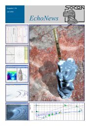
<strong>EchoNews</strong>
Seite 2 Page 2<br />
Hohlraumvermessung<br />
Cavity surveying<br />
Auswertung<br />
Interpretation<br />
Forschung & Entwicklung<br />
Research & Development<br />
Markscheidewesen<br />
Mine - surveying<br />
Seminare<br />
Seminars<br />
www.socon.com
Seite 3 Page 3<br />
<strong>EchoNews</strong><br />
Inhalt / Contents<br />
Autoren / Author<br />
Dr. S. Großwig<br />
GESO GmbH,<br />
Jena<br />
Dr. M. Krieter<br />
PLE GmbH,<br />
Essen<br />
O. Reckler<br />
DEEP. GmbH,<br />
Bad Zwischenahn<br />
Hanna Linn Wiegel<br />
Universität Gießen,<br />
Gießen<br />
H. Engelke,<br />
H. Fiebig,<br />
K. Gotthardt,<br />
F. Haßelkus,<br />
M. Külshammer,<br />
Dr. A. Reitze,<br />
A. Stille,<br />
H. von Tryller,<br />
SOCON Sonar Control<br />
Kavernenvermessung<br />
GmbH,<br />
Giesen<br />
Impressum<br />
Herausgeber:<br />
SOCON Sonar Control<br />
Kavernenvermessung<br />
GmbH,<br />
Schachtstr. 3 b,<br />
D-31180 Giesen<br />
Tel.: +49 50 66 6 08-0<br />
E: info@socon.com<br />
Redaktionsteam:<br />
Hartmut von Tryller,<br />
Herbert Fiebig,<br />
Dr. Andreas Reitze,<br />
Thomas Weiler<br />
Druck & Verarbeitung:<br />
Copyland GmbH,<br />
Hildesheim<br />
Hohlraumvermessung / Cavity surveying ——————————————————————<br />
Dr. S. Großwig<br />
Faseroptische Temperaturmessung<br />
Fibre Optic Temperature Technique 4<br />
H. David Permanente Ultraschallüberwachung in Kavernen<br />
Blanket control systems in combination with ultrasonics 5<br />
F. Haßelkus Vermessung der Kaverne Altaussee SCH1<br />
Surveying of the Altaussee Sch1 cavern 6<br />
H. von Tryller Physikalische Kriterien zur sicheren und optimalen Abtastung der<br />
Kavernenwand, Teil 1<br />
Physical criteria for the reliable and optimal sampling of cavern walls, Part 1 8<br />
Forschung & Entwicklung / Research & Development ————————————————<br />
Dr. A. Reitze<br />
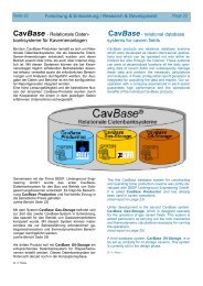
CavBase - Relationale Datenbanksystem für Kavernenanlagen<br />
CavBase - relational database system for cavern fields 22<br />
O. Reckler CavBase - Production / CavBase - Production 23<br />
Dr. M. Krieter<br />
Entwicklung von CavBase Gas Storage<br />
Development of CavBase Gas Storage 25<br />
CavInfo Software Suite / CavInfo Software Suite 26<br />
M. Külshammer CavView - Darstellung und Analyse von Kavernenvermessungen<br />
CavView - display and analysis of cavern surveys 27<br />
M. Külshammer CavLog - Darstellung und mathematische Bearbeitung von LOG-Daten<br />
CavLog - display and mathematical processing of log data 28<br />
A. Stille CavMap - Verwaltung und Visualisierung von Kavernenfeldern<br />
CavMap - management and visualization of cavern fields 30<br />
M. Külshammer CavDat - ein neues Programm zur Interpretation ...<br />
CavDat - The new program for interpreting cavern surveys ... 31<br />
H. Engelke Probennehmersonde - neu und modular<br />
Sampling tool - now redesigned and modular 32<br />
K. Gotthardt Modulare Kabelwinde / Modular cable winch 33<br />
K. Gotthardt Neue LKW-gestützte Hochdruckschleusen-Einheit<br />
New Truck-based high-pressure lubricator units 35<br />
Markscheidewesen / Mine - surveying ———————————————————————<br />
Dr. A. Reitze<br />
KARISDAT um Module für GIS-Anwendungen erweitert<br />
KARISDAT expanded by modules for GIS applications 36<br />
Rubriken / Column —————————————————————————–———————<br />
H. Fiebig Freud und Leid mit der SCC-Zertifizierung<br />
Joy and sorrow with SCC certification 37<br />
Personelle Veränderungen / Staff changes 34<br />
Kaverne und Kunst / Cavern and Art ——————————————–—————————–<br />
H. L. Wiegel Wellen über den Kanälen / Waves over the channels 39<br />
Titelbild:<br />
Hartmut von Tryller<br />
H. von Tryller Eine Geschichte von Musik und Kaverne / A story of music and cavern 40<br />
H. von Tryller Kavernen - eine Inspiration für Künstler / Caverns as an inspiration for artists 40
Seite 4 Hohlraumvermessung / Cavity surveying<br />
Page 4<br />
FASEROPTISCHE TEMPER ATUR-<br />
MESSUNG<br />
Untersuchung von Bohrlochkomplettierung und<br />
Prozessabläufen in unterirdischen Gasspeichern<br />
mit Hilfe faseroptischer Temperaturmessungen<br />
Die Temperaturverteilung in einem unterirdischen Gasspeicher<br />
und deren zeitliche Änderungen sind Schlüsselparameter,<br />
um die Betriebsbedingungen zu erfassen<br />
und zu überwachen. So hängt die Speicherkapazität<br />
(Gasvolumen und Einspeise- / Ausspeiseraten) ganz<br />
wesentlich von der Temperatur ab. Dasselbe gilt für<br />
den Taupunkt, den Dampfdruck und chemische Reaktionen.<br />
Die Optimierung der Betriebsbedingungen wie<br />
z.B. auch des Methanol-Inhibitionsregimes erfordern<br />
genaue Kenntnisse über die Temperaturverteilung in<br />
Abhängigkeit von Tiefe und Zeit in Gasspeicherbohrungen<br />
und im Innern von Kavernen. Bei bekanntem Kopfdruck<br />
kann über die gemessene Temperatur-<br />
Tiefenverteilung das Druckprofil berechnet werden. Mit<br />
der Liberalisierung des Gasmarktes können schnelle<br />
Gasumschlagzeiten und somit kurzfristige Wechsel von<br />
Ein- und Ausspeisung verbunden sein. Damit ergeben<br />
sich erweiterte Anforderungen, die thermodynamischen<br />
Prozesse in Kavernen zu erfassen.<br />
Der Joule-Thomson-<br />
Effekt bildet die physikalische<br />
Grundlage<br />
für die Kontrolle und<br />
Über wachung des Roh r-<br />
stranges und technischer<br />
Einbauten. Er<br />
definiert die Beziehungen<br />
zwischen Druckänderungen<br />
und Temperaturänderungen.<br />
Unregelmäßigkeiten<br />
im Druckverlauf und<br />
insbesondere ein leckagebedingter<br />
lokaler<br />
Druckabfall führen zu Temperaturänderungen und lassen<br />
sich durch Temperaturmessungen einfach detektieren<br />
und lokalisieren. Aus Temperaturmessungen, die<br />
zeitgleich über die gesamte Strecke einer Bohrung unter<br />
unterschiedlichen Betriebsbedingungen im Steigrohr<br />
oder im Ringraum durchgeführt werden, lassen sich detaillierte<br />
Aussagen über die Lage und Größe einer L e-<br />
ckage im Rohrstrang (z.B. an Korrosionsstellen, Verschraubungen,<br />
Dichtungseinheiten oder Schiebestücken)<br />
oder in der Verrohrung ableiten. Auch Hinterrohreffekte<br />
(z.B. Gasfluss hinter der Verrohrung) beeinflussen<br />
das Temperaturfeld in dem Rohrstrang. An einem<br />
Flüssigkeitsspiegel treten Temperaturänderungen auf,<br />
die durch eine kurzzeitige Druckentlastung verstärkt<br />
werden können, so dass die Lage eines Flüssigkeitsspiegels<br />
in Bohrungen oder in einer Kaverne bestimmt<br />
und überwacht werden kann.<br />
FIBRE OPTIC TEMPERATURE<br />
TECHNIQUE<br />
Distributed fibre optic temperature sensing technique<br />
for surveying borehole constructions and<br />
thermodynamic processes in underground gas<br />
storage facilities<br />
The temperature distribution inside an underground<br />
storage facility and its variation with time are key p a-<br />
rameters for assessing and surveying the operating<br />
conditions. In combination with geological and petrophysical<br />
data, long-term temperature monitoring of underground<br />
storage facilities can provide thermodynamic<br />
information on reservoir dynamics. The storage capacity<br />
(gas volume and injection- / withdrawal rates) depends<br />
strongly on temperature. The same is true for<br />
the dew point, the vapour pressure and chemical reactions.<br />
Knowing exactly about temperature vs. depth<br />
and time in a production well of a cavern or aquifer<br />
storage facility is crucial when it comes to optimising<br />
the methanol inhibition regime (methanol/glycol) and<br />
the operating conditions. From a known well head pressure<br />
and the thermodynamic equation of state one can<br />
derive the pressure profile based on the temperature<br />
profile. Liberalization of the gas market means short<br />
change-over times with short-term gas injection and<br />
gas withdrawal. Therefore, it is a key problem to understand<br />
the thermodynamic processes in caverns.<br />
The Joule-Thomson effect gives the physical basement<br />
for surveying the string, the borehole construction and<br />
technical installations. Temperature distribution measurements<br />
made simultaneously along the full length of<br />
a production string under varying operating conditions<br />
and especially before, during and after pressure drawdown<br />
in the annulus provide detailed information on<br />
temperature anomalies which may be due to leaks from<br />
the production string (e.g. at corrosion pits, collars,<br />
screwings, simple or over-shot sealing units and travel<br />
joints) or the casing or to flows occurring behind the<br />
casing. Because of the Joule-Thomson effect, any leak<br />
will result in a temperature drop. By comparison with<br />
defined starting temperature conditions, leaks can thus<br />
easily be detected and located. Moreover, the temperature<br />
dependence of pressure opens the chance to<br />
measure and survey fluid levels in aquifer boreholes.
Seite 5 Hohlraumvermessung / Cavity surveying<br />
Page 5<br />
Die Erfassung und Überwachung der Temperaturverteilung<br />
geben daher dem Betreiber eines unterirdischen<br />
Speichers wichtige Informationen. Allerdings ist es erforderlich,<br />
dass die Messungen zeitgleich über die gesamte<br />
Messstrecke bei hoher Temperatur- und Ortsauflösung<br />
und einem dichten Zeitraster (z.B. 1 min) erfolgen können,<br />
um schnell ablaufende Prozesse zu erfassen und zu lokalisieren.<br />
Die konventionellen Bohrlochtemperaturmessungen<br />
können diese Anforderungen nicht erfüllen. Das Verfahren<br />
der faseroptischen Temperaturmessung eröffnet<br />
hier ganz neue Möglichkeiten, da es die zeitgleiche Temperaturmessung<br />
über lange Strecken mit der geforderten<br />
Orts- und Temperaturauflösung auch in kurzer Messabfolge<br />
ermöglicht. Dieses Verfahren bietet sich daher für Untersuchungen<br />
in unterirdischen Gasspeichern (Kavernen<br />
und Produktionssonden von Aquiferspeichern) an. Seit<br />
<strong>fast</strong> 10 Jahren liegen Erfahrungen mit faseroptischen<br />
Messungen in Kavernen und Aquiferspeichern vor. Erste<br />
Messungen erfolgten 1992 in der Bohrung Mwd 5 des Kavernenfeldes<br />
Mittenwalde und 1993 in der Bohrung B41<br />
des Aquiferspeichers Buchholz.<br />
Thus, measuring and surveying of the temperaturedepth<br />
distribution gives important information to the<br />
operator of an underground gas storage facility. Conventional<br />
temperature well logging does not allow<br />
measuring temperature vs. depth and time simultaneously<br />
for the full length of a production string with<br />
a high depth and temperature resolution. Fibre-optic<br />
temperature sensing opens new possibilities to<br />
measure the time-depth distribution of temperature in<br />
caverns and productions strings of aquifer storage<br />
facilities. First fibre-optic temperature measurements<br />
in underground gas storage facilities were taken in<br />
1992 in the Mittenwalde 5 cavern well and in 1993 in<br />
the B 41 production well at the Buchholz aquifer gas<br />
storage facility southwest of Berlin.<br />
Dr. S. Großwig<br />
Dr. S. Großwig<br />
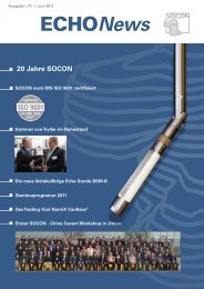
Blanket Control Systeme in<br />
Kombination mit Ultraschall<br />
Blanket control systems in<br />
combination with ultrasonics<br />
Aus der Diskussion mit einem langjährigen<br />
Kunden in Thailand ist die Idee zur<br />
Erweiterung der dort vielfach eingesetzten<br />
Blanket Control Systeme vom Typ<br />
BCS-Value entstanden.<br />
Da für die Installation der BCS Anlagen<br />
ein Kabel bis zur BCS -Sonde verlegt werden<br />
muss, ist die Erweiterung der Sonde<br />
um Ultraschallmesstechnik für die Bestimmung<br />
der horizontalen Ausdehnung<br />
der Kaverne eine bestechende Idee.<br />
Nach kurzen Vorversuchen konnte nac h-<br />
gewiesen werden, dass die direkte Übertragung<br />
der Hochspannungsultraschallpulse<br />
und der empfangenen Echos über<br />
das verwendete Kabel möglich ist.<br />
Für die neu konzipierte Kombination von<br />
Blanket Control Systemen mit Ultraschalltechnik<br />
wird eine kleine Sende-/<br />
Empfangsbaugruppe obertägig eingesetzt,<br />
so dass in der Kaverne ausschließlich<br />
der Ultraschallwandler mit einer kleinen<br />
Signaltrennbaugruppe eingebaut<br />
wird.<br />
Diese Signaltrennbaugruppe kann zwischen<br />
einem horizontal und einem vertikal ausgerichteten<br />
Wandler umschalten und die Signale der BCS-Value Anlage<br />
von den Ultraschallsignalen trennen.<br />
Cable<br />
BSC Tool<br />
Interface<br />
Transducer 1<br />
Discussions with a long<br />
standing client in Thailand led<br />
to the idea of adding another<br />
feature to the Blanket Control<br />
System of type BCS -Value<br />
that is widely used in that<br />
country. As a cable has to be<br />
laid in any case to the BCS<br />
tool in the BCS installation, it<br />
is a tempting idea to extend<br />
the tool capabilities to include<br />
ultrasonics for determining<br />
the horizontal extent of the<br />
cavern. After short tests it<br />
could be proved that it is possible<br />
to directly transfer the<br />
high-voltage ultrasonic pulses<br />
and the received echos via<br />
the installed cable.<br />
This newly designed combination<br />
of BCS with ultrasonics<br />
makes use of a small<br />
transmitter/receiver unit at the<br />
surface so that only the ultrasonic<br />
transducer with a small<br />
signal separator component has to be installed in the<br />
cavern. This separator component can switch be-<br />
Transducer 2 (H)
Seite 6<br />
Hohlraumvermessung / Cavity surveying Page 6<br />
Der Horizontalwandler kann in einer Richtung die Radiusentwicklung<br />
der Kaverne dokumentieren, während<br />
der annähernd vertikal betriebene Wandler eine zusätzliche<br />
Kontrolle der Lage des Blanketspiegels von unten<br />
ermöglicht.<br />
Die Auswertung der Signale erfolgt in der installierten<br />
Demonstrationsanlage derzeit nur über ein Digitaloszilloskop,<br />
mit dem der zeitliche Abstand von Sendesignal<br />
und Echo ermittelt und mit einer angenommenen<br />
Schallgeschwindigkeit von 1800 Meter/sec auf den Radius<br />
rückgeschlossen werden kann.<br />
Der Mehraufwand für die Ultraschallmesstechnik in<br />
Kombination mit einer BCS -Value Anlage ist dann b e-<br />
sonders lohnend, wenn in mehreren Kavernen ein<br />
Wandler montiert wird und die Elektronik mit der Sende-/Empfangseinheit<br />
obertägig nur einmal benötigt<br />
wird.<br />
Die uns vorliegenden Ergebnisse der Versuchsanlage<br />
bestätigen die sinnvolle Einsetzbarkeit dieses neuen<br />
Systems auch im laufenden Solbetrieb und zeigen, wie<br />
mit relativ kleinem Aufwand zusätzlich Messdaten zum<br />
sicheren Betrieb von Solegewinnungskavernen gewonnen<br />
werden können.<br />
H. David<br />
tween a horizontally and vertically oriented transducer<br />
and can separate the BCS -value signals from the ultrasonic<br />
signals. The horizontal transducer can document<br />
the development of the cavern radius in one direction,<br />
whereas the transducer operating almost vertically provides<br />
an additional control from below of the position of<br />
the blanket level.<br />
In the existing test installation the signals are interpreted<br />
at present using only a digital oscilloscope. This<br />
is used to determine the difference in time between the<br />
transmitted signal and the echo from which, applying an<br />
assumed acoustic velocity of 1800m/s, the radius of the<br />
cavern can be derived.<br />
The extra costs of combining ultrasonic technology with<br />
BCS-Value equipment is especially worthwhile if transducers<br />
are installed in several caverns and they can all<br />
use just one transmitter/receiver unit at the surface. Re -<br />
sults available to us from the test installation confirm<br />
that the use of this new system is beneficial even in<br />
leaching operations in process and show how at relatively<br />
little cost additional survey data can be acquired<br />
for safely operating brine production caverns.<br />
H. David<br />
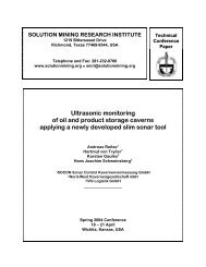
Bild rechts:<br />
Außenansicht der Kaverne<br />
Altaussee SCH1<br />
(rote Fahne zeigt in Richtung<br />
Nord)<br />
Right:<br />
View outside of the<br />
Altaussee SCH1 cavern<br />
(red flag points towards north)<br />
Bild unten:<br />
Messcrew mit Equipment<br />
bereit zur Einfahrt<br />
Below:<br />
Survey crew with equipment<br />
ready for entry<br />
Vermessung der Kaverne Altaussee SCH1<br />
mit Ultraschall- und Lasersonde<br />
Untertägige Ultraschallvermessungen von<br />
Kavernen im Haselgebirge sind - neben den<br />
bei jeder Ultraschallvermessung auftretenden<br />
Fragen und Schwierigkeiten - mit einigen<br />
Besonderheiten verknüpft. Bedingt<br />
durch die geringen freien Arbeitshöhen über<br />
dem Bohrloch und die engen Zuwegungen<br />
zu den Kavernen ist spezielles Equipment<br />
bzw. sind spezielle Verfahrensweisen nötig,<br />
um eine Vermessung durchzuführen.<br />
Im Haselgebirge sind extrem inhomogene<br />
Lagerstättenbedingungen gegeben. Der<br />
Salzgehalt variiert stark über die Teufe und<br />
es ist ein hoher Gehalt an unlöslichen B e-<br />
standteilen gegeben. Am Beispiel der Kaverne<br />
Altaussee SCH 1 der Salinen Austria AG,<br />
die im Rahmen der SMRI Herbsttagung<br />
2002 begangen wird, soll dies exemplarisch<br />
geschildert werden.<br />
Es handelt sich bei dieser Kaverne um eine<br />
Bohrlochsonde, die untertage im Salzbergbau<br />
Altaussee/Österreich vom Scheibenhorizont<br />
aus abgeteuft wurde. Die Kaverne wurde<br />
mit Luft-Blanket gesolt. Bis Solende wur-<br />
Ultrasonic and Laser<br />
surveying of the<br />
Altaussee Sch1 cavern<br />
Subsurface ultrasonic surveys of caverns in<br />
the Haselgebirge are associated with a<br />
number of specific characteristics - in addition<br />
to the queries and special features that<br />
generally occur in ultrasonic surveys. The<br />
restricted headroom above the borehole<br />
and the narrow access routes to the cavities<br />
necessitate the use of special equipment<br />
and special ways of working in order to<br />
carry out surveys here.<br />
In the Haselgebirge the deposit conditions<br />
are extremely inhomogeneous. The salt<br />
content varies greatly with depth and there
Seite 7<br />
Hohlraumvermessung / Cavity surveying Page 7<br />
Oben:<br />
Innenansicht der Kaverne<br />
Altaussee SCH1<br />
Above:<br />
View inside the Altaussee<br />
SCH1 cavern<br />
Bild unten links:<br />
Der Messtechniker mit seiner<br />
Apparatur vor Ort<br />
Below left:<br />
Survey technician with his<br />
equipment on site<br />
Bild Unten rechts:<br />
Einfahrt der Echosonde in die<br />
Bohrung<br />
Below right:<br />
Running the echo tool into the<br />
hole<br />
den drei Vermessungen durchgeführt.<br />
Da sich der Luft-Solespiegel im Dachbereich<br />
befindet bzw. kurz darunter abgesackt<br />
ist, kommt es zu Reflexionen des Ultraschalls<br />
am Spiegel, die ein vollständiges<br />
Vermessen der Decke verhindern. Bedingt<br />
durch das Entlasten der Kaverne kommt es<br />
zu Ausgasungserscheinungen in der Sole,<br />
die vom Boden zur Decke hin zunehmend<br />
die abgestrahlte Ultraschall energie abso r-<br />
bieren.<br />
Die Kaverne war zu diesem Zeitpunkt im<br />
oberen Teil mit stark untergrädiger Sole<br />
gefüllt, was zu stark teufenabhängigen Variationen<br />
in der Schallgeschwindigkeit führt,<br />
die Strahlbeugungen beim Durchlaufen<br />
dieser Variationszonen hervorruft.<br />
Die Interpretation war dementsprechend<br />
aufwendig und konnte - bedingt durch den<br />
Spiegel unterhalb der Decke - größere Bereiche<br />
der Decke nicht direkt erfassen.<br />
Eine nachfolgende Vermessung mit einem<br />
Bohrlochlaser wurde bei teilentleerter K a-<br />
verne im April 2002 durchgeführt. Diese<br />
Vermessung diente dazu, die Decke und<br />
den oberen Teil ohne die vorher erwähnten<br />
erschwerenden Randbedingungen zu erfassen<br />
und eine vollständige 3D-<br />
Modellierung zu ermöglichen.<br />
F. Haßelkus<br />
is a large proportion of insoluble constituents.<br />
A description of these general conditions<br />
and how they are dealt with is given<br />
here by referring to the Altaussee SCH 1<br />
cavern of Salinen Austria AG which will be<br />
entered during the SMRI fall meeting 2002.<br />
In the case of this cavern a borehole was<br />
drilled and equipped underground from a<br />
sublevel drift in the Altaussee salt mine in<br />
Austria. The cavern was leached with a compressed<br />
air blanket. Up until the end of<br />
leaching three surveys were carried out; the<br />
third survey was performed approximately<br />
six months before the end of leaching.<br />
As the air-brine interface is somewhere in<br />
the roof zone or has dropped just below it,<br />
reflections of the ultrasonic beam occur at<br />
the interface and these prevent the roof from<br />
being fully surveyed. As a result of the pressure<br />
in the cavity being released gas bubbles<br />
are produced in the brine and these increasingly<br />
absorb the emitted ultrasonic e n-<br />
ergy when rising from the floor to the roof. At<br />
the time of the survey the upper part of the<br />
cavern was filled with significantly unsaturated<br />
brine, which led to large depthdependent<br />
variations in the acoustic velocity.<br />
The acoustic beams were diffracted when<br />
they passed through zones with such variations.<br />
The interpretation was correspondingly complicated<br />
and it was not possible to directly<br />
determine large parts of the roof due to the<br />
air- brine interface being just below t he roof.<br />
A subsequent survey was therefore carried<br />
out using a borehole laser tool after the cavern<br />
had been partially emptied. The aim of<br />
this survey was firstly to determine the roof<br />
and the upper part of the cavern without being<br />
affected by the previously mentioned<br />
problematic measuring conditions, and secondly<br />
to enable 3D modeling.<br />
Among other things this detailed survey<br />
served to fix a suitable place for an access<br />
into the cavern to be able to go inside the<br />
cavern during the SMRI fall meeting 2002.<br />
The idea was stimulated and promoted by<br />
SOCON, because within the framework of<br />
two SOCON customer's seminars (in 1994<br />
and 1998) the inspection of a cavern interior<br />
at the Salinen Austria AG had caused big<br />
response from our customers.<br />
However, the very plastic 3D representation<br />
gives a clear spatial image of this cavern to<br />
all which cannot participate going into the<br />
cavern.<br />
F. Haßelkus
Seite 8<br />
Hohlraumvermessung / Cavity surveying Page 8<br />
Physikalische Kriterien zur sicheren und optimalen Abtastung der Kavernenwand<br />
Physical criteria for the reliable and optimal sampling of cavern walls<br />
Teil 1<br />
Part 1<br />
Einsatz des Echolots zur Ermittlung<br />
der Bodenfreiheit unter Booten<br />
und Ortung von Fischschwä rmen.<br />
Application of the echo sounder<br />
for determining the clearance<br />
underneath boats and for<br />
locating shoals of fish.<br />
Ultraschall als Hilfsmittel zur<br />
Entfernungsmessung<br />
Historisch gesehen lassen sich die E-<br />
chosysteme zur Vermessung von K a-<br />
vernen auf das Echolot für Fischerboote<br />
zurückführen. Die Echolote wurden<br />
eingesetzt, um die Befahrbarkeit<br />
(Bodenfreiheit) unterhalb des Bootes<br />
zu ermitteln und um Fischschwärme<br />
orten zu können.<br />
Noch heute sind weltweit Sonarsonden<br />
im Einsatz, die auf dieser Basis arbeiten.<br />
Es wurden lediglich die Bauform<br />
geändert und die Ultraschallgeber<br />
dreh- und kippbar aus geführt. Wurden<br />
beim ursprünglichen Echolot die Lotwerte<br />
über die Fahrstrecke aufgetragen,<br />
werden die „Lotwerte“ bei den<br />
Sonarsonden mit jedem Stepp des<br />
Schrittmotors - um den errechneten<br />
Winkelstepp versetzt - in einer Ebene<br />
um die Messachse herum aufgetragen.<br />
Diese Systeme eignen sich ausgezeichnet<br />
für Trendmessungen. Jede<br />
Reflexion verdichtet die sich darstellende<br />
Strukturinformation.<br />
Wurden früher Reflexionen durch<br />
Schwärzung eines Papierstreifens oder<br />
durch Leuchtspuren auf dem Oszillographen<br />
sichtbar gemacht, so erfolgt<br />
heute die Ausgabe über Computer.<br />
Eine adäquate Berücksichtigung der<br />
physikalischen Rahmenbedingungen,<br />
wie sie bei Messungen in Kavernen e r-<br />
forderlich ist, stellt erhöhte Anforderungen<br />
an Vermes sungssysteme. Es<br />
geht bei diesen Systemen nicht mehr<br />
darum, ob unter dem Schiffsrumpf etwas<br />
Platz oder ein Fischschwarm vorhanden<br />
ist. Einsparungen in diesem<br />
Bereich erlauben zwar einfache und<br />
kostengünstige Systeme, liefern aber<br />
auch nur Ergebnisse, die dem Ursprung<br />
dieser Entwicklung entsprechen,<br />
nämlich Tendenz- und Trendaussagen!<br />
Ultrasonics as a distance<br />
measuring aid<br />
Echometric systems used for surveying<br />
caverns are historically based on the<br />
echo sounder fitted in fishing boats.<br />
Echo sounders were used to determine<br />
the navigability, i.e. the clearance below<br />
the boat, and to locate shoals of fish.<br />
Nowadays throughout the world echo<br />
tools are still in use that work on the<br />
same principle. Solely the design shape<br />
has been modified and the sonic transducer<br />
been given the ability to rotate and<br />
tilt. Whereas with the original echo<br />
sounder the soundings were plotted<br />
along the coarse covered, the<br />
”soundings” of the sonar tools are recorded<br />
every time the tool motor advances<br />
through a set angle and plotted<br />
in a plane around the survey axis. These<br />
systems are ideally suited for making<br />
general trend surveys. Every reflection<br />
increases the density of the displayed<br />
structural information. In the past the r e-<br />
flections were made visible by black<br />
marks on a paper strip or by streaks of<br />
light on an oscilloscope, nowadays output<br />
is via computer.<br />
In the surveying of caverns it is necessary<br />
to sufficiently consider the physical<br />
background conditions, and cons e -<br />
quently this demands more from the surveying<br />
systems used. In these systems it<br />
is no longer a question of whether under<br />
the boat’s hull there is enough room or<br />
there is a shoal of fish. Simple and lowprice<br />
systems certainly allow savings to<br />
be made in this area, but they supply<br />
results that reflect solely the origin of this<br />
development, i.e. results that indicate<br />
general trends only.<br />
Anwendung des Ultraschalls<br />
in Kavernen<br />
In unzugänglichen Bereichen ist man,<br />
wenn die Form und das Volumen dieser<br />
Bereiche erfasst werden sollen, auf<br />
Application of ultrasonics in<br />
caverns<br />
If the shape and volume of accessible<br />
zones of caverns are to be determined<br />
then it is necessary to have survey
Seite 9<br />
Hohlraumvermessung / Cavity surveying Page 9<br />
spezielle, der Aufgabenstellung angepasste Messgeräte<br />
angewiesen. Messgeräte, die mit möglichst hoher Genauigkeit<br />
die Bereiche abtasten und alle Unregelmäßigkeiten,<br />
Hintersolungen etc. erfassen. Zur Anwendung kommen<br />
Laser- und Ultraschallsysteme. Lasersysteme werden immer<br />
dann eingesetzt, wenn Luft das umgebende Medium<br />
bildet und die Dämpfung des Ultraschalls aufgrund der<br />
hohen Absorption in Luft einen qualitativ befriedigenden<br />
oder ausreichenden Einsatz nicht mehr erlaubt. Demg e -<br />
genüber werden Vermessungen in flüssigkeitsgefüllten<br />
oder gasgefüllten Hohlräumen und Kavernen mit Ultraschall<br />
durchgeführt. Lasersysteme können in flüssigen<br />
Medien, bedingt durch Brechung und Dämpfung des Laserlichtimpulses,<br />
nicht eingesetzt werden. Für Messungen<br />
in gasförmigen Kohlenwasserstoffen wurden zwar von uns<br />
mit hohem Forschungs- und Kostenaufwand (ca. 0,7 Mill.<br />
Euro) Lasersysteme entwickelt und erprobt, die Ergebnisse<br />
waren bzw. sind aber aufgrund physikalischer Eigenschaften<br />
mangelhaft.<br />
Zu jeder Kavernenvermessung mit Ultraschall gehört auch<br />
die Erfassung der Temperatur und Schallgeschwindigkeit<br />
im Vermessungsbereich als minimale Parameterergänzung.<br />
Es macht keinen Sinn, auf der einen Seite Daten zu<br />
sammeln und auf der anderen Seite wesentliche Param e -<br />
ter durch Annahmen, wie bei Modellierungen zur Vervollständigung<br />
der Daten üblich, einzubringen.<br />
Im Gegensatz zu allen anderen Sonarsonden verfügen<br />
die von SOCON eingesetzten Sonden neben einem CCL<br />
auch über ein SUPER - CCL. Diese Sensoren verlängern<br />
zwar die Sonden in ihren Ausmaßen, ermöglichen aber,<br />
neben anderen Funktionen, eine präzise Einhängung des<br />
Messgerätes an einem Referenzpunkt bzw. dienen zur<br />
Überprüfung und Kontrolle der Tiefenmessvorrichtung.<br />
Eine Vielzahl weiterer Sensoren, wie Natural-Gamma,<br />
Taupunkt, etc., runden den optimierten und sicheren<br />
Messeinsatz ab.<br />
Zum besseren Verständnis der Kriterien, die an ein Kavernenvermessungsgerät<br />
gestellt werden, oder - besser g e-<br />
sagt - gestellt werden sollten, erfolgt die Beschreibung<br />
und Erläuterung in vier Bereichen. Jeder Bereich für sich<br />
hat dabei einen wesentlichen Einfluss auf die Messge -<br />
nauigkeit.<br />
1. Positionsbestimmung der Sonarsonde in der Kaverne<br />
als Voraussetzung verwertbarer Ergebnisse,<br />
2. Sensorik neben dem Ultraschall für die Aufnahme von<br />
Logs zur Optimierung der Genauigkeiten,<br />
3. Qualität und Optimierungen des Ultraschallmessstrahls<br />
in Sonarsonden,<br />
4. Interpretationsvoraussetzungen für die Auswertung<br />
und Bewertung von Sonardaten.<br />
In der vorliegenden Ausgabe der Echo- News werden<br />
schwerpunktmäßig die Bereiche 1 und 2 mit einem kleinen<br />
Vorgriff auf die beiden anderen Bereiche behandelt.<br />
Die Bereiche 3 und 4 werden dann ausführlicher in der<br />
nächsten Ausgabe I / 03 der <strong>EchoNews</strong> in 2003 erörtert.<br />
→<br />
equipment that is specially suited to the job in hand,<br />
and moreover that samples the cavern surfaces and<br />
records all the irregularities, leached pockets and so<br />
on with the greatest possible accuracy. Both laser and<br />
ultrasonic systems are applied here.<br />
Laser systems are used whenever air is the surrounding<br />
medium and when the attenuation in ultrasonic<br />
systems, resulting from the high absorption in air, no<br />
longer allows them to produce qualitatively satisfactory<br />
or generally acceptable results. On the other hand u l-<br />
trasonic systems are used for surveying in liquid-filled<br />
and gas-filled caverns and cavities. Due to the refraction<br />
and attenuation of the laser pulse, laser systems<br />
cannot be used in liquid media. Although we have invested<br />
a great deal of research and money (approx.<br />
0.7 million euros) in developing and testing laser systems<br />
for surveying in gaseous hydrocarbons, the r e-<br />
sults obtained up to now have been poor owing to the<br />
prevailing physical characteristics.<br />
Every ultrasonic cavern survey must be supplemented<br />
at the very minimum with a recording of the temperature<br />
and acoustic velocity in the survey range. It does<br />
not make any sense to acquire data on the one side<br />
and on the other side to assume other important p a-<br />
rameters, as is usual in modeling in order to complete<br />
the data set.<br />
As opposed to all other sonar tools, the tools used by<br />
SOCON have, in addition to a CCL, a SUPER - CCL.<br />
Although these sections make the overall tool longer,<br />
they enable the survey tool, besides other functions, to<br />
be accurately tied to a reference point and provide a<br />
means of testing and checking the depth control<br />
equipment. Numerous other sensors, such as naturalgamma,<br />
dewpoint and so on, are employed to ensure<br />
an optimized and safe survey performance.<br />
In order to make more understandable what criteria<br />
cavern survey equipment should meet, the explanation<br />
of the overall situation is split up into four topics.<br />
Each of these four topics individually has a considerable<br />
influence on the survey accuracy.<br />
1. Determination of position of the sonar tool in the<br />
cavern as a requirement for usable results,<br />
2. Logging tools in addition to ultrasonics for optimizing<br />
accuracy,<br />
3. Quality and optimization of the ultrasonic measuring<br />
beam in sonar tools,<br />
4. Interpretation requirements for evaluating and<br />
interpreting sonar data.<br />
In this issue of the <strong>EchoNews</strong> the focus is on topics 1<br />
and 2 while the other two topics are just touched upon.<br />
Topics 3 and 4 will be discussed in more detail in the<br />
next issue of the <strong>EchoNews</strong>, which is to be published<br />
in 2003. →
Seite 10<br />
Hohlraumvermessung / Cavity surveying Page 10<br />
Positionsbestimmung der<br />
Sonarsonde in der Kaverne als<br />
Voraussetzung verwertbarer<br />
Ergebnisse<br />
Unabhängig von den Sonarqualitäten<br />
eines Systems ist die Positionsbestimmung<br />
des Messgerätes entscheidend,<br />
denn auf der Basis der Positionsbestimmung<br />
bauen alle weiteren Daten auf.<br />
Für eine genaue Positionsbestimmung<br />
sind die folgenden Teilaufgaben von besonderer<br />
Bedeutung:<br />
• Tiefenpositionsbestimmung der<br />
Sonarsonde am Bohrlochkabel,<br />
• Positionierungsprinzip der Messköpfe<br />
für Sonarsysteme,<br />
• Azimutale Positionierung des<br />
Messgerätes,<br />
• Kipppositionierung des Messgerätes,<br />
• Fixierung des Messkopfes während<br />
der Messwerterfassung.<br />
Die Tiefenpositionsbestimmung hängt<br />
wesentlich ab:<br />
• von der Qualität des eingesetzten Kabelmesswagens<br />
(Tiefenmesssystem,<br />
Reproduzierbarkeit der Messtiefe bei<br />
unterschiedlichen Fahrbewegungen und<br />
Richtungen),<br />
• von der verfügbaren Sensorik in der<br />
Messsonde, wie CCL und SUPER-CCL<br />
zur Einhängung und Einhängungsüberprüfung<br />
an Muffen und/oder Rohrschuhen<br />
als Referenztiefe.<br />
Aus diesem Grund setzt SOCON, sofern<br />
das Messkabel mit <strong>eigene</strong>m Gerät g e-<br />
stellt wird, eine haus<strong>eigene</strong> computerkontrollierte<br />
Windentechnik ein - eine<br />
Technik, die alle wesentlichen Faktoren<br />
und Kabelbeiwerte einbezieht und zudem<br />
wesentlich zur Sicherheit des Fahrbetriebes<br />
beiträgt.<br />
Bei anderen Systemen wird aus Kostengründen<br />
ausschließlich eine Tiefenpositionsbestimmung<br />
über ein auf dem Kabel<br />
mitlaufendes Messrad durchgeführt.<br />
Determination of position of the<br />
sonar tool in the cavern as a requirement<br />
for usable results<br />
Irrespective of the sonar quality of a system,<br />
it is the position determination of<br />
the measuring tool that is decisive b e-<br />
cause all the other data are based on<br />
this.<br />
The following procedures are particularly<br />
significant for accurate position determination:<br />
• determination of depth position of the<br />
sonar tool on the borehole cable<br />
• positioning principle of measuring<br />
heads in sonar systems<br />
• azimuthal positioning of survey tool<br />
• tilt positioning of survey tool<br />
• securing of measuring head when<br />
recording the survey points.<br />
Depth determination depends essentially<br />
on:<br />
• the quality of the cable survey truck<br />
used (depth measuring system, reproducibility<br />
of survey depths after various<br />
movements and direction changes)<br />
• the sensors installed in the survey<br />
tool, such as CCL and SUPER-CCL,<br />
which are used for tying the depth and<br />
checking the depth-ties to collars and/or<br />
casing shoes to obtain a reference<br />
depth.<br />
Due to the above mentioned reasons,<br />
SOCON performs surveys using inhouse-developed,<br />
computer-controlled<br />
winch technology – provided our winch<br />
equipment is made available with the<br />
survey cable – a technology that draws<br />
upon all the important factors and cable<br />
correction values and moreover contributes<br />
a great deal to the safety of winch<br />
operations. In other systems, the depth<br />
determination is, for reasons of cost, carried<br />
out solely by a depth measuring<br />
wheel that is turned by the cable.
Seite 11<br />
Hohlraumvermessung / Cavity surveying<br />
Page 11<br />
Das Positionierungsprinzip der<br />
Messköpfe für Sonarsysteme<br />
Die Abbildung zeigt das patentierte Prinzip<br />
der SOCON Sonarsonden. Hier unterscheidet<br />
sich die Technik von allen am<br />
Markt verfügbaren Sonden. Zwar verfügen<br />
alle Sonden über einen Kompass, jedoch<br />
ist der Kompass bei diesen Sonden nicht<br />
fest mit dem Ultraschallmesskopf gekoppelt.<br />
Er befindet sich im oberen, frei am<br />
Kabel hängenden und nicht zur Positionierung<br />
beitragenden Teil der Sonde. Diese<br />
Bauweise ermöglicht den Bau von kurzen<br />
und preiswerten Sonden.<br />
Die zur Entfernungsmessung verwendeten<br />
Ultraschallsensoren werden in diesen<br />
Sonden durch Steppmotoren und Steppzähler<br />
(1 Stepp = 0.00x Grad) relativ von<br />
einer durch den Kompass erfassten Startrichtung<br />
aus gesteuert. Das Getriebespiel<br />
zwischen Motor und Messkopf (z. B.<br />
durch Alterung!) bleibt ebenso unberücksichtigt<br />
wie Schlupf- und Steppverluste<br />
durch Reibung, etc. oder die Eigenbewegung<br />
der Sonde durch das Kabel<br />
inkl. den Strömungseinflüssen in der Kaverne.<br />
Eine Erfassung der Richtung für<br />
jeden aufgenommenen Entfernungswert<br />
findet nicht statt; anstelle einer gemessenen<br />
Richtung liefert der Steppzähler die<br />
Richtung.<br />
(RICHTUNG = Startrichtung + X Stepps *<br />
Steppfaktor)<br />
Da die Schritte des Steppmotors, dividiert<br />
durch die Getriebeuntersetzung, sehr<br />
klein werden, ergeben sich fantastische<br />
Winkelschrittdaten für eine technische Beschreibung<br />
des Systems. Diese Systeme<br />
können ihre Schwäche der richtungsgenauen<br />
Zuordnung von Laufzeitdaten und<br />
Richtungsdaten nur minimieren, wenn Bewegungsmeldungen<br />
des oberen Teils<br />
(Gesamtanordnung der Sonde steht nicht<br />
mehr in der Ausgangsposition) zum A b-<br />
bruch und zu einem erneuten Scanvorgang<br />
führen. Dies führt zu langen frustrierenden<br />
Messzeiten.<br />
Da keine protokollierende Aufzeichnung<br />
der Messabläufe stattfindet, wie dies bei<br />
SOCON erfolgt, ist letztendlich eine Überprüfung<br />
unmöglich. Eine Näherung der<br />
Daten am Ende des Scanvorgangs mit<br />
den Daten vom Anfang ist aufgrund unterschiedlicher<br />
Winkelgeschwindigkeiten<br />
The positioning principle of measuring<br />
heads in sonar systems<br />
The figure shows the patented principle of the SO-<br />
CON sonar tools. The technology of these tools<br />
differs from that of all other tools on the market.<br />
Even though all other tools are equipped with a<br />
compass, the compass in them is not rigidly connected<br />
to the ultrasonic measuring head. Instead<br />
it is located in the upper part of the tool which is<br />
freely suspended on the cable and which does not<br />
contribute to the positioning. This type of design<br />
enables tools to be made that are short and<br />
cheap.<br />
The ultrasonic sensors used for distance<br />
measuring in these tools are<br />
controlled by incremental motors and<br />
step counters<br />
(1 step = 0.00x degrees)<br />
relative to a start direction<br />
determined by the<br />
compass. In such tool<br />
design the play in the<br />
gears (e.g. as a result of<br />
aging) which becomes<br />
noticeable between the<br />
motor and the measuring<br />
head is not considered,<br />
nor are the losses<br />
resulting from slippage<br />
caused by friction, nor<br />
the tool’s own movement<br />
caused by the cable<br />
and the influence of<br />
fluid flow in the cavern.<br />
Here the direction is not<br />
measured for each recorded<br />
distance; instead<br />
Druckausgleich<br />
Druckfeste<br />
Steckverbindung<br />
Druckausgleich<br />
Druckfeste<br />
Steckverbindung<br />
Horizontalsensoren<br />
Vertikalsensor<br />
Neigung<br />
Steuerung<br />
Kippantrieb<br />
of a measured direction the step counter supplies<br />
just a direction, namely<br />
DIRECTION = start direction + X steps * step factor.<br />
As the steps of the incremental motor, divided by<br />
the gear reduction, are very small, the technical<br />
description of the system can boast fantastic incremental<br />
angular data. These systems can minimize<br />
their shortcomings in allocating traveltime<br />
data to the right direction only if a movement of<br />
the upper part of the tool (overall tool arrangement<br />
no longer in starting position) cancels recording so<br />
that a new scan can be carried out. This results in<br />
long and frustrating survey times. And as a general<br />
event protocol of the survey procedure is not<br />
recorded, similar to the protocol recorded in SO-<br />
CON surveys, it is impossible to check what has<br />
happened. Even if the data made at the end of the<br />
scan procedure approximate the data made at the<br />
Stabilisierung<br />
Kippsteuerung<br />
Drehsteuerung<br />
Steuerung<br />
Drehantrieb<br />
Drehantrieb<br />
Richtungssensor<br />
Kippantrieb<br />
Winkelsensor<br />
Richtung
Seite 12<br />
Hohlraumvermessung / Cavity surveying Page 12<br />
während des Vorganges kein Indiz für eine<br />
durchweg sichere Messwerterfassung und<br />
nur in kreisrunden Kavernenformen ohne<br />
größere Bedeutung.<br />
beginning this does not indicate that the<br />
data a cquisition is completely correct owing<br />
to the different angular velocities that occur<br />
during recording. Only in circular cavern<br />
shapes is the angular velocity of little signif i-<br />
cance.<br />
Positionierungsprinzip der Messköpfe<br />
(System SOCON)<br />
Positioning principle of the measuring heads<br />
(SOCON system)<br />
Kommunikationslinien:<br />
j Ultraschallsignal (Echogramme), Signalbeobachtung<br />
und Auswertung im Messwagen<br />
k Servosystem Kippmotor – Messkopf mit Steuerungskopplung<br />
und Visualisierung<br />
• Servosystem Azimutsteuerung Kompass - Messkopf<br />
mit Steuerungskopplung und Visualisierung<br />
m<br />
Kontrolle der Azimutsteuerung<br />
• Kotrolle der Kippsteuerung<br />
A<br />
Stabilisator<br />
MD Motor Azimutpositionierung<br />
GD Getriebe Azimutpositionierung<br />
B<br />
Azimutmodul<br />
Kompassmodul<br />
C Kippmodul<br />
MK Motor Kippmodul<br />
GK Getriebe Drehmodul<br />
Communication lines:<br />
j Ultrasonic signal (echograms), signal observation and<br />
interpretation in the survey truck<br />
k Servo system of tilt motor – measuring head with control<br />
coupling and visualization<br />
• Servo system of azimuthal drive compass - measuring<br />
head with control coupling and visualization<br />
m<br />
Control of azimuth drive<br />
• Control of tilt drive<br />
A<br />
Stabilizer<br />
MD Motor for azimuth positioning<br />
GD Gears for azimuth positioning<br />
B<br />
Azimuth module<br />
Compass module<br />
C Tilt module<br />
MK Motor of tilt module<br />
GK Gearing of rotary module<br />
D<br />
Neigungssensor<br />
D<br />
Tilt sensor<br />
E<br />
Schwenkbereich des Ultraschallsensors<br />
0 – 90, -90 – 0 Grad<br />
E<br />
Swivel range of ultrasonic sensor<br />
0 – 90, -90 – 0 degrees
Seite 13<br />
Hohlraumvermessung / Cavity surveying<br />
Page 13<br />
Das Azimutmodul (B) bildet mit MD, GD und<br />
dem Kompassmodul eine geschlossene<br />
Servoeinheit, die über (3) von der Erdoberfläche<br />
aus gesteuert und überwacht wird.<br />
Der Messkopf mit den Ultraschallwandlern<br />
(Ultraschallaugen) ist starr mit dieser Einheit<br />
gekoppelt. So ist sichergestellt, dass für jede<br />
Sonaraufnahme auch ein zeitgleich g e-<br />
messener Richtungswert vorliegt.<br />
Um Regelschwingungen, hervorgerufen<br />
durch den Servobetrieb, in Verbindung mit<br />
dem Bohrlochkabel zu vermeiden, wird der<br />
obere Teil der Sonde (bis GD) mit Stabilisatoren<br />
fixiert. Das Kippmodul (C) bildet mit<br />
MK, GK und dem Neigungssensor D eine<br />
geschlossene Servoeinheit, die über (2) von<br />
der Erdoberfläche gesteuert und überwacht<br />
wird. Der Messkopf mit den Ultraschallwandlern<br />
ist ebenfalls starr mit dem Modul<br />
gekoppelt, so dass auch hier sichergestellt<br />
ist, dass für jede Sonaraufnahme auch ein<br />
zeitgleich gemessener Neigungswert vo r-<br />
liegt.<br />
Zusammenfassung: Typ SOCON<br />
Durch den patentierten Aufbau und das<br />
Prinzip des Messkopfes kann jedes der drei<br />
im Messkopf integrierten Ultraschallaugen<br />
kontrolliert und optimiert in jede Erfassungsposition<br />
gesteuert werden. Jede Position<br />
der Ultraschallsensoren wird durch zeitgleich<br />
ermittelte Neigungs- und Richtungsdaten<br />
dokumentiert. Die Ultraschallsensoren,<br />
ein Vertikalauge für –90 Grad bis 0<br />
Grad (Bodenbereich bis horizontal) und<br />
zwei Ultraschallaugen horizontal bis + 90<br />
Grad stellen die Abtastung der Kavernenwand<br />
sicher. Durch die Verwendung von<br />
zwei horizontalen Augen ergibt sich eine<br />
Vielzahl von Optimierungen und Verfahrenstechnologien.<br />
Durch den Aufbau des<br />
Messkopfes ist ein Verharren der Ultraschallaugen<br />
in einer Messposition sichergestellt.<br />
Ein Verharren ist bei Kavernenvermessungen,<br />
wo die Laufzeit eines Schallimpulses<br />
von der Sonde zum Messobjekt und<br />
wieder zur Sonde gemes sen wird, mindestens<br />
für einen Messzyklus nötig.<br />
Da sich von Messpunkt zu Messpunkt die<br />
Reflexionseigenschaften durch Entfernungsänderungen<br />
und/oder die Kavernenwandstruktur<br />
ändern können, ist ein Verharren<br />
auf einer Position zur Optimierung der<br />
Ultraschallaugen hinsichtlich energetischer,<br />
aber auch anderer Rahmenbedingungen<br />
not wendig. Zur Registrierung von gesicherten<br />
Ultraschalldaten sollten (müssen) in j e-<br />
der Messposition die Sonardaten zur Verif i-<br />
zierung und Korrelation mehrfach ermittelt<br />
The azimuth module (B) forms together<br />
with MD, GD and the compass module a<br />
contained servo unit that is controlled and<br />
monitored via (3) from the surface. The<br />
measuring head with the ultrasonic transducers<br />
is rigidly connected to this unit,<br />
which ensures that for every sonar measurement<br />
a direction measurement is<br />
made at the same time.<br />
In order to avoid hunting caused by servo<br />
operation in connection with the borehole<br />
cable, the upper part of the tool (to GD) is<br />
secured by stabilizers. The tilt module (C)<br />
forms together with MK, GK and the tilt<br />
sensor (D) a contained servo unit that is<br />
controlled and monitored via (2) from the<br />
surface. The measuring head with the u l-<br />
trasonic transducers is likewise rigidly<br />
connected to this unit so that here too it is<br />
ensured that for every sonar measurement<br />
a tilt measurement is made at the<br />
same time.<br />
Summary: SOCON type<br />
The patented design and the principle behind<br />
the measuring head makes it possible<br />
to control each of the three ultrasonic<br />
sensors integrated in the head and to optimally<br />
move them into any scanning position.<br />
Every position of the ultrasonic sensors<br />
is documented by tilt and direction<br />
data recorded at the same time. The ultrasonic<br />
sensors, one vertical ”eye” for –90°<br />
to 0° (floor area to horizontal) and two u l-<br />
trasonic ”eyes” for the horizontal to +90°,<br />
ensure full sampling of the cavern wall.<br />
Having two horizontal ”eyes” provides n u-<br />
merous ways of optimization and possible<br />
recording procedures.<br />
The design of the measuring head is such<br />
that the ultrasonic sensors can be maintained<br />
at one survey position. It is necessary<br />
to maintain the sensors at one position<br />
in cavern surveys, in which the<br />
traveltime of an acoustic pulse from the<br />
tool to the survey point and back is measured,<br />
for at least one measuring cycle.<br />
As reflection characteristics can change<br />
from one survey point to another depending<br />
on the distance and/or the structure of<br />
the cavern wall it is necessary to maintain<br />
the ultrasonic sensors at one position so<br />
as to optimize them with regard to energy<br />
as well as the other prevailing conditions.<br />
Moreover in order to measure secure ultrasonic<br />
data, the data should, and indeed<br />
must, be multiply recorded at each survey<br />
position to enable it to be verified and cor-
Seite 14<br />
Hohlraumvermessung / Cavity surveying<br />
Page 14<br />
werden und das Echogramm, wie bei<br />
seismischen Messungen auch, zeitgleich<br />
an die Erdoberfläche zur Bewertung und<br />
Optimierung übertragen werden.<br />
related; the echogram, as is the case in<br />
seismic surveys, should then be simultaneously<br />
transferred to the surface for<br />
evaluation and optimization.<br />
Positionierungsprinzip der Messköpfe<br />
(„andere Systeme“)<br />
Kommunikationslinien:<br />
o Countermeldung Steppmotor auf Schritt X und<br />
Auswertergebnis der Sonardaten<br />
p Kompasswert beim Start des Scanvorgang<br />
q Messkopf drehe X Steppschritte weiter<br />
r Messkopf gehe X Steppschritte zur nächsten Kippposition<br />
auf oder ab<br />
Kompassmodul<br />
Positioning principle of the measuring heads<br />
(”other systems”)<br />
Communication lines:<br />
o Counter message of incremental motor at step X and<br />
interpreted result of sonar data<br />
p Compass reading at start of scanning<br />
q Measuring head to rotate further X steps<br />
r Measuring head to go up or down X steps to the next<br />
tilt position<br />
Compass module<br />
zur Azimutpositionierung<br />
for azimuth positioning<br />
MD<br />
Motor Azimutpositionierung<br />
MD<br />
Motor for azimuth positioning<br />
GD<br />
Getriebe Azimutpositionierung<br />
GD<br />
Gears for azimuth positioning<br />
B<br />
Rotationspositionierung<br />
B<br />
Rotational positioning<br />
zur Kipppositionierung<br />
for tilt positioning<br />
MK<br />
Motor Kippmodul<br />
MK<br />
Motor of tilt module<br />
GK<br />
Getriebe Kippmodul<br />
GK<br />
Gearing of tilt module<br />
C<br />
Kippgelenk<br />
C<br />
Tilt joint<br />
E<br />
Schwenkbereich des Ultraschallsensors<br />
< +/- 90 Grad<br />
E<br />
Swivel range of ultrasonic sensor<br />
< +/- 90 degrees
Seite 15<br />
Hohlraumvermessung / Cavity surveying<br />
Page 15<br />
Durch diese Aufbauweise ergibt sich ein<br />
einfaches und schnelles System, das im Vorbeifahren,<br />
ähnlich wie bei einer Radaraufnahme,<br />
die Kavernenwand abtastet. Im Gegensatz<br />
zu einem Radarsystem ist jedoch das<br />
Messgerät nicht starr auf einer Position fixiert.<br />
Das Messsystem hängt an einem flexiblen<br />
Bohrlochkabel, hat Eigenschwingung und<br />
kann sich in der Winkelgeschwindigkeit beim<br />
Scanvorgang durch Eigenmomente<br />
(Sondenmasse und Massenverlagerung<br />
durch Auskippen des Sonarauges) wie auch<br />
externe Momente vom Kabel oder Medium,<br />
etc. ändern. Eine Fixierung des Messsystems<br />
durch Stabilisatoren wäre zwingend erforderlich.<br />
Durch Steppverluste (keine Seltenheit) und<br />
durch Getriebespiel (Alterung) ist zudem eine<br />
exakte Positionsbestimmung nicht möglich.<br />
Zwar werden die Daten in Schritten von z. B.<br />
2.81 Grad aufgetragen - ein Wert, der große<br />
Genauigkeit suggeriert, sich aber in Wirklichkeit<br />
nur aus der Anzahl der Steppmotorschritte<br />
* Getriebefaktor * Schrittweite pro Stepp +<br />
Kompasswert beim Start ergibt. Würde dieses<br />
System im kontrollierten Positionsmode<br />
arbeiten, würde es sich, da es nicht fixiert ist,<br />
aufschaukeln und eine Messwerterfassung<br />
unmöglich machen.<br />
Sonden mit kontinuierlicher Vorwärtsbewegung<br />
und Auslösung der Messung, wenn der<br />
Vorgabewert des Steppzählers erreicht ist,<br />
ergeben zudem Verschleifungen des Messwertes<br />
in Abhängigkeit von der Laufzeit<br />
(Entfernung) und der Drehgeschwindigkeit.<br />
(Zum Zeitpunkt des Ultraschallsendeimpulses<br />
steht die Sonde in Richtung X, zum Zeitpunkt<br />
des Empfangs der Ultraschallantwort in<br />
Richtung X+Stepp/sec*delta(t)). Da es sich<br />
bei Sonarmessungen wie beim Radar um<br />
Laufzeitmessungen handelt, die Laufzeiten<br />
aber bis zu 700 000 mal größer sind, hat Delta<br />
(t) keinen unerheblichen Einfluss auf die<br />
Verschleifung.<br />
Es ist so, als ob ein Fotograf mit einer Belichtungszeit<br />
von 1/10 sec aus dem fahrenden<br />
Auto ein gestochen scharfes Bild aufnehmen<br />
möchte!<br />
Um beim Beispiel des Fotografen zu bleiben:<br />
für einfache Ansprüche mag das Bild reichen,<br />
für präzise Aufnahmen aber reicht keine Fotobox.<br />
Es müssen zu mindest die Qualität der<br />
Kamera, die Belichtung, die Blende und die<br />
Belichtungszeit für die Aufgabenstellung optimiert<br />
werden. →<br />
Such a setup yields a <strong>fast</strong> and simple system<br />
that samples the cavern wall in a circular<br />
sweep similar to a radar scan. However,<br />
as opposed to a radar system the survey<br />
instrument is not rigidly fixed in one position.<br />
The measuring system is suspended on a<br />
flexible borehole cable, it exhibits natural v i-<br />
brations and can vary in angular velocity<br />
during scanning as a result of its own moment<br />
of force (i.e. the tool mass and the<br />
mass displacement caused by tilting the sonar<br />
sensor) as well as of external moments<br />
of force caused by the cable and medium<br />
etc. Fixing the measuring system by means<br />
of stabilizers really is necessary.<br />
In addition, determination of the exact position<br />
is not possible owing to slippage (which<br />
is not rare) and play in the gears (as a result<br />
of aging). Although data may be plotted in<br />
steps for example of 2.81 degrees, a value<br />
that suggests high accuracy, the fact is that<br />
such values result simply from the number of<br />
incremental motor steps * gear factor * step<br />
width per step + compass value at the start.<br />
If this system were operated in controlled<br />
position mode, it would, as it is not fixed,<br />
start to oscillate so that it would be impossible<br />
to record survey values.<br />
Tools which move forwards continuously,<br />
with the measurement being made when a<br />
set value of the step counter is reached,<br />
smear the survey values to an amount depending<br />
on the traveltime (or distance) and<br />
the speed of rotation. This means if the tool<br />
is facing in direction x when the sonic pulse<br />
is emitted, then when the reflected sonic<br />
pulse is received the tool is facing in the d i-<br />
rection x + steps/s * delta(t). Both radar and<br />
sonar are based on traveltime measurements,<br />
but in the case of sonar surveys the<br />
traveltimes are up to 700,000 times longer,<br />
which means that delta(t) can have a significant<br />
influence on the amount of smearing.<br />
This is comparable to a photographer taking<br />
a picture with an exposure time of 1/10 second<br />
through the window of a moving car in<br />
the hope of getting a well-focused picture. If<br />
what is required is only basic, then this picture<br />
may well suffice, however, if more precise<br />
pictures are needed a box camera is<br />
inadequate. At the very least it is necessary<br />
to optimize the quality of the camera, the aperture<br />
and the exposure time to satisfy the<br />
requirements of the job to be done. →
Seite 16<br />
Hohlraumvermessung / Cavity surveying<br />
Page 16<br />
Positionierung der<br />
“Sonaraugen“<br />
in SOCON Sonden<br />
Positioning of the<br />
“sonar eyes”<br />
in SOCON tools<br />
Die Sonden verfügen über computerkontrollierte<br />
Servosysteme, die nicht nur<br />
die Funktionalitäten der Ultraschallsensorik<br />
(siehe nächste Ausgabe der Echo-<br />
News ) überwachen und Messpunkt für<br />
Messpunkt eine Optimierung erlauben,<br />
sondern aktiv die Positionsüberwachung<br />
und Optimierung der “Sonaraugen“ vornehmen.<br />
Der Kompass in den Sonden ist starr<br />
mit den Ultraschallsensoren gekoppelt<br />
und folgt allen Bewegungen des Messkopfes.<br />
Die zu vermessende Richtung<br />
wird vom obertägigen System mit einer<br />
einstellbaren Toleranz vorgegeben, der<br />
Messkopf positioniert sich und gibt,<br />
wenn sich die Sonde im Toleranzfenster<br />
fixiert hat, den Messvorgang frei. Mit den<br />
ermittelten Sonardaten der Kavernenwand<br />
und einer Vielzahl weiterer Parameter<br />
werden die tatsächliche Richtung<br />
im Toleranzfenster, die aktuelle Neigung<br />
des Kopfes und die energetischen Vorgaben<br />
inkl. der aktuellen Sonarfrequenz,<br />
Periodenfolge, etc. mit übertragen.<br />
Die Fixierung der Sonde in der Messrichtung<br />
wird durch die Verwendung von<br />
Kreiselstabilisatoren gewährleistet - eine<br />
aufwendige, aber wirkungsvolle Technik!<br />
Nur durch das Fixieren der Sonde in der<br />
Messrichtung kann sich das System auf<br />
die Reflexionseigenschaften und Bedingungen<br />
in einer bestimmten Richtung<br />
einstellen. Die Bedingungen können<br />
Richtung für Richtung unterschiedlich<br />
sein.<br />
In jeder Messposition werden die Sonardaten<br />
zur Sicherstellung einer übersteuerungsfreien<br />
und eindeutigen Messwerterfassung<br />
online beobachtet und für Interpretationen<br />
und zur Beweissicherung,<br />
wie in der Seismik auch, dokumentiert.<br />
Geschieht dies nicht, sind die Daten der<br />
Vermessung nicht überprüfbar. Zudem<br />
handelt es sich um Zeitmessungen, g e-<br />
nauer gesagt um Laufzeitmessungen,<br />
bei denen man, bevor sich die Sonde<br />
weiterbewegt, den Messvorgang abwarten<br />
muss.<br />
Wird dann, wie bei SOCON üblich, jeder<br />
Messpunkt zur Plausibilitätsprüfung und<br />
Korrelation mehrfach gemessen, ist ein<br />
Stillstand der Sonde während des Messvorgangs<br />
zwingend erforderlich. Ein<br />
SOCON tools are fitted with computercontrolled<br />
servo systems that not only<br />
monitor the functionality of the ultrasonic<br />
sensor system (read the next issue of<br />
the <strong>EchoNews</strong>) and enable optimization<br />
survey point for survey point, but also<br />
actively optimize the “sonar eyes” and<br />
monitor the positioning of them.<br />
The compass installed in the tools is<br />
rigidly fixed to the ultrasonic sensors and<br />
follows every movement of the measuring<br />
head. The direction to be measured,<br />
within an adjustable tolerance limit, is<br />
transferred from the surface system to<br />
the measuring head, which positions i t-<br />
self and, when the tool is set within the<br />
tolerance window, initiates the measuring<br />
routine. Besides the acquired sonar<br />
data of the cavern wall and numerous<br />
other parameters, the true direction in<br />
the tolerance window, the tilt of the head<br />
at the time of measurement and the energy<br />
data, such as sonar frequency and<br />
period sequence, are transferred for r e-<br />
cording.<br />
Only when the tool is fixed in the survey<br />
direction is it possible for the system to<br />
adjust itself to the reflection characteristics<br />
and conditions in that specific direction.<br />
This is important because the conditions<br />
can vary from direction to direction.<br />
Gyro stabilizers are used to maintain<br />
the tool in the survey direction<br />
– a complicated but effective technique.<br />
Sonar data are monitored online at every<br />
survey position to ensure the measured<br />
values are unequivocal and free from<br />
overamplification. They are then documented<br />
for interpretation and reference,<br />
as is the case in seismic work. If this is<br />
not done the surveyed data could not be<br />
checked at a later date. Moreover, it<br />
must be realized that we are dealing with<br />
time measurements, or more precisely<br />
traveltime measurements, so that the<br />
measuring procedure must be completed<br />
before the tool is advanced to the<br />
next survey point.<br />
If, as is usual in SOCON surveys, every<br />
survey point is multiply measured for<br />
correlation purposes and as a plausibility<br />
check, then it is essential that the tool is<br />
Abbildung:<br />
Ausbreitung des Sonarstrahls<br />
Fig:<br />
Propagation of the sonar beam<br />
Abbildung:<br />
Echogramm, Auszug einer Messreihe<br />
Fig:<br />
Echogram – extract from a survey
Seite 17<br />
Hohlraumvermessung / Cavity surveying<br />
Page 17<br />
Wechselbetrieb von Stillstand (messen)<br />
und Positionierungsbetrieb ist ohne Kreiselstabilisatoren<br />
ebenso unmöglich wie<br />
eine Anpassung der Ultraschallsensoren<br />
an die Reflexionsbedingungen.<br />
Um die möglichen Restfehler von Sensoren<br />
zu minimieren, werden von allen<br />
Sensoren beim Programmstart die<br />
“persönlichen Daten“ abgefragt und entsprechende<br />
Kalibrierdaten aus der D a-<br />
tenbank nachgeladen. So existiert u. a.<br />
für jeden Kompass eine Tabelle zur Korrektur<br />
der Deviation.<br />
Für die Ausrichtung des Kippkopfes<br />
wird, ähnlich der Azimutsteuerung des<br />
Kompasses, ein im Messkopf integrierter<br />
Neigungssensor herangezogen. Der<br />
Neigungssensor steuert und überwacht<br />
die Positionierung. Auf diese Weise ist<br />
es möglich, jeden Kippwinkel zwischen 0<br />
und +/- 90 Grad anzufahren. Da mit dem<br />
Neigungssensor auch die aktuelle Neigung<br />
der Sonde erfasst wird, ist es möglich,<br />
neben Neigungs profilen auch geneigte<br />
Messschnitte zu fahren, die aufgrund<br />
einer Führung der Sonde im Bohrloch<br />
oder durch die Rohrtour für jede<br />
Messrichtung eine unterschiedliche Neigung<br />
des Messkopfes (taumeln) ergeben.<br />
Die Daten werden korrekt in X-,Yund<br />
Z-Werte transformiert und in den<br />
Datenbestand einbezogen.<br />
Die “Ultraschallaugen“, die sich wenige<br />
Zentimeter unterhalb des Neigungssensors<br />
befinden, sind über einen<br />
Schnellverbinder austausch- und somit<br />
an die Aufgabenstellung anpassbar.<br />
Durch eine spezielle Technologie der<br />
hausintern entwickelten Ultraschallaugen<br />
ist ein weites Spektrum von Systemen<br />
mit hoher Bündelung für unterschiedliche<br />
Sonarimpedanzen verfügbar<br />
(siehe TEIL 2 in der nächsten Ausgabe<br />
der <strong>EchoNews</strong>).<br />
Für spezielle Anwendungen, Medien<br />
oder Casingtypen steht eine Vielzahl von<br />
“Sonaraugen“ zum Austausch bereit. →<br />
kept still during the measuring procedure.<br />
Without gyro stabilizers it would<br />
not only be impossible to change between<br />
the stationary measuring mode<br />
and the positioning mode but also to a d-<br />
just the ultrasonic sensors to the reflection<br />
conditions.<br />
To minimize any possible residual error<br />
of the sensors, the ”individual sensor<br />
data” are requested from all the sensors<br />
at the start of the program and the corresponding<br />
calibration data are loaded<br />
from the database. Thus for every compass<br />
there is, amongst other things, a<br />
deviation correction table.<br />
An inclination sensor integrated in the<br />
measuring head is used for aligning the<br />
tilt head, similar to the azimuth control<br />
of the compass. Thea inclination sensor<br />
controls and monitors the positioning. In<br />
this way it is possible to move the head<br />
to any tilt angle between 0 and +/- 90<br />
degrees. As the inclination sensor can<br />
also measure any inclination of the tool,<br />
inclined survey sections can be surveyed<br />
in addition to tilt sections. These<br />
inclined survey sections, in which the<br />
tool is positionined in the borehole or in<br />
the casing, result in a different inclination<br />
of the measuring head for each survey<br />
direction. The data are transformed correctly<br />
into x, y and z-values and added<br />
to the database.<br />
Numerous types of ”sonar eyes” are<br />
available for special applications, different<br />
media as well as casing types. The<br />
”sonar eyes”, which are positioned just a<br />
few centimeters below the inclination<br />
sensor, are fitted with a quick-release<br />
connector so that they can be easily e x-<br />
changed for the ”sonar eyes” most suitable<br />
for the job to be carried out. Based<br />
on the special technology of the „sonar<br />
eyes”, which was developed in-house,<br />
there is a wide range of systems with<br />
high beam concentration available for<br />
various sonar impedances (read Part 2<br />
in the next issue of the <strong>EchoNews</strong> ). →<br />
Abbildung:<br />
Restfehler der Richtungsbestimmung nach<br />
Ansatz der Korrekturtabelle<br />
Fig:<br />
Residual error of the direction determination<br />
applying the correction table
Seite 18<br />
Hohlraumvermessung / Cavity surveying<br />
Page 18<br />
Sensorik neben dem Ultraschall<br />
für die Aufnahme von Logs zur<br />
Optimierung der Genauigkeiten<br />
Die Aufnahme von Logs im Zusammenhang<br />
mit einer Sonarvermessung,<br />
wie Natural-Gamma, Schallgeschwindigkeit,<br />
Druck, CCL, Temperatur, etc., stellt<br />
die Ergänzung - um nicht zu sagen - die<br />
Voraussetzung für Kavernenvermessungen<br />
dar. Durch Temperaturmessungen<br />
sind Änderungszonen erkennbar,<br />
die entsprechend beachtet werden<br />
können! Temperaturvariationen innerhalb<br />
einer Kaverne haben erheblichen<br />
Einfluss auf den Sonarmessstrahl. Um<br />
Strahlbrechungen bzw. Beugungen zu<br />
minimieren, wird der Messablauf durch<br />
Informationen aus den Logaufnahmen<br />
optimiert und gezielt an die Aufgabenstellung<br />
angepasst.<br />
Mit Hilfe von CCL bzw. SUPER-CCL<br />
werden Tiefenkontrollen und Einhängungen<br />
durchgeführt und die Qualität der<br />
Kabelwinde überwacht.<br />
Eine weitere, entscheidende Information<br />
liefert jedoch die Schallgeschwindigkeitsmessung.<br />
Wie eingangs erwähnt,<br />
erfolgt die Abtastung der Kavernenwand<br />
mit Ultraschall generell nur durch Laufzeitmessung.<br />
Gemessen wird, wie viel<br />
Zeit ein Schallimpuls vom Messgerät zur<br />
Kavernenwand und wieder zurück benötigt.<br />
Um diese Werte (Hin- und Rückweg)<br />
in Entfernungen umrechnen zu<br />
können, muss die Geschwindigkeit, mit<br />
der sich ein Schallimpuls in dem Medium<br />
ausbreitet, zuvor ermittelt werden.<br />
Auch hier wird bei den meisten Systemen<br />
weltweit gespart!<br />
„Temperatureinflüsse existieren nicht,<br />
die Kabelwinde ist hervorragend, eine<br />
Einhängung unnötig, die Schallgeschwi<br />
ndigkeit innerhalb einer Kaverne ist<br />
konstant und schätzbar!“<br />
Und falls doch gemessen wird, kann niemand<br />
das Resultat der Messung überprüfen.<br />
Passt das gemessene Volumen<br />
nicht zu dem erwarteten Volumen, kann<br />
der Schätzwert der Schallgeschwindigkeit<br />
zur Korrektur neu geschätzt werden!<br />
Vertrauen ist <strong>gut</strong>, Kontrolle ist besser. Ist<br />
etwas nicht direkt kontrollierbar, dann ist<br />
Qualität ent scheidend und vertrauensbildend.<br />
Qualität und somit größtmögliche<br />
Sicherheit werden nur erreicht, wenn alle<br />
relevanten physikalischen Parameter<br />
erfasst, beachtet und dokumentiert werden.<br />
Logging tools in addition to ultrasonics<br />
for optimizing accuracy<br />
The recording of logs such as naturalgamma,<br />
acoustic velocity, pressure,<br />
CCL and temperature logs as part of a<br />
sonar survey provides at the very least<br />
supplementary data, but should be seen<br />
rather as a prerequisite for cavern surveys.<br />
Temperature measurements for<br />
instance indicate where zones with temperature<br />
changes exist in the cavern, so<br />
that these can be appropriately monitored.<br />
Temperature variations within a<br />
cavern significantly affect the sonar<br />
measuring beam. To minimize beam refraction<br />
and diffraction the survey procedure<br />
can be optimized using log information<br />
and specifically adjusted to meet the<br />
prevailing survey requirements.<br />
CCL and SUPER-CCL tools are used to<br />
make depth checks and depth ties and<br />
to monitor the quality of the cable winch.<br />
Additional decisive information, however,<br />
is provided by acoustic velocity measurements.<br />
As mentioned above, the cavern<br />
wall is sampled using ultrasonics<br />
based on traveltime measurements.<br />
What is measured is the time an ultrasonic<br />
pulse takes to travel from the survey<br />
tool to the cavern wall and back<br />
again. In order to be able to convert<br />
these measured values (outward and<br />
return path) into distances, it is necessary<br />
to first determine the velocity with<br />
which an ultrasonic pulse propagates in<br />
the medium.<br />
The majority of systems in the world<br />
skimp on the requirements in this area<br />
too:<br />
”There is no such thing as temperature<br />
effects, the cable winch is excellent,<br />
depth ties are unnecessary, the acoustic<br />
velocity in the cavern is constant and<br />
can be estimated!”<br />
And if by some chance measurements<br />
are made, nobody can check the results.<br />
If the measured volume does not agree<br />
with the expected volume, the estimated<br />
acoustic velocity can be adjusted to<br />
make a volume correction. As the saying<br />
goes: ”it is good to trust things, but it is<br />
better to check them”, but if something<br />
cannot be checked directly, then it is the<br />
quality that is decisive and forms the basis<br />
of trust. And quality, and consequently<br />
the best possible safety, can be<br />
achieved only if all the relevant physical<br />
parameters are recorded, considered<br />
and documented.<br />
Beispiel einer LOG-Aufnahme in einer<br />
Gaskaverne<br />
Example of a LOG-recording in a gas<br />
cavern
Seite 19<br />
Hohlraumvermessung / Cavity surveying<br />
Page 19<br />
Das SOCON<br />
BSE-Schallgeschwindigkeitsmodul<br />
besteht aus einem kompensierten,<br />
mehrstufigen System mit Differenzausgleich.<br />
Von einem Ultraschallsende- und<br />
Empfangswandler werden an das Medium<br />
angepasste Schallimpulse in programmierbaren<br />
Sende- und Empfangszyklen<br />
ausgesandt. Die Schallimpulse<br />
treffen dabei auf zwei räumlich<br />
versetzte Reflektoren. Um einen <strong>gut</strong>en<br />
Medienaustausch im Bereich der Messstrecke<br />
zu erreichen, ist das System<br />
nach außen hin offen, d. h. frei vom Medium<br />
umspült. Da sich bei solchen System<br />
aber zwangsläufig Ablagerungen<br />
auf den Reflektoren bilden, die die Messung<br />
verfälschen würden, werden diese<br />
Reflektoren nur auf ihren Unterseiten genutzt,<br />
d. h. die Schallimpulse werden<br />
von unten nach oben gesendet. Jede<br />
Antwort enthält den Hin- und Rückweg<br />
und schließt somit Dopplereffekte durch<br />
Messfahrten aus.<br />
Neben den beiden Laufzeiten bis zu den<br />
Reflektoren (t kurz und t lang ), lässt sich<br />
auch die Differenz der beiden Laufzeiten<br />
(t diff ) zwischen den Reflektoren nutzen.<br />
Eingebaute Mikroprozessoren und Softwareroutinen<br />
ermitteln für jede der drei<br />
Referenzstrecken die Schallgeschwindigkeit<br />
und führen eine Fehlerbetrachtung<br />
durch. Die elektronisch bedingten<br />
Fehleranteile wie Systemverzögerungen,<br />
die nur in den Strecken „lang“ und „kurz“<br />
enthalten sind, entfallen für die Differenzstrecke.<br />
Es verbleibt lediglich ein<br />
systemunabhängiger Fehler, der - bedingt<br />
durch das Auswerteverfahren -<br />
verbleibende Phasenfehler enthalten<br />
kann, die durch Mikroprozessoren und<br />
Software kompensiert werden.<br />
Unterschiede oder Abweichungen zwischen<br />
den Sonden werden von der Software<br />
berücksichtigt. Die Software fragt<br />
dazu jede Sensoreinheit auf Seriennummer<br />
und Eigenschaften ab und verwendet<br />
dann die zugehörige Kalibriertabelle.<br />
Dieses Verfahren wird für alle in SO-<br />
CON - Sonden eingesetzten Sensoren<br />
angewendet.<br />
Um eine möglichst hohe Genauigkeit zu<br />
erhalten, hat die Messstrecke eine Länge<br />
von 50 cm und arbeitet mit einer zeitlichen<br />
Auflösung von 10 ns. Bei einer<br />
Schallgeschwindigkeit von z.B. 1800 m/s<br />
und einer Laufzeit von 278 µs für t lang<br />
ergeben sich somit ausreichend lange<br />
Laufzeiten, um exakte und reproduzier-<br />
The SOCON<br />
BSE acoustic velocity module comprises<br />
a compensated, multistage system<br />
with differential compensation. Ultrasonic<br />
pulses suitably adapted to the medium<br />
are emitted in programmable emission<br />
and reception cycles from an ultrasonic<br />
transmitter/receiver transducer. The<br />
emitted pulses are reflected from two<br />
reflectors that are mutually offset. To ensure<br />
that there is a good flow of medium<br />
over the measuring range, the system is<br />
open on the outside, i.e. it has direct<br />
contact with the medium. In such a system,<br />
however, it is unavoidable that d e-<br />
posits build up on the reflectors, which<br />
would falsify the measurements made.<br />
To avoid this only the underside of the<br />
reflectors are used, i.e. the ultrasonic<br />
pulses are transmitted upwards. As every<br />
response contains the outward and<br />
return path any Doppler effects that may<br />
exist are eliminated.<br />
In addition to the two traveltimes to and<br />
from the reflectors (t short and t long ), the<br />
difference between the two traveltimes<br />
(t diff ) can be used. Microprocessors fitted<br />
in the tool and software routines determine<br />
the acoustic velocity for the three<br />
reference distances and carry out an error<br />
analysis. The error components<br />
caused by the electronics, such as system<br />
delays (which are contained solely<br />
in the ”long” and ”short” distances) do<br />
not apply to the differential distance. All<br />
that is left is a system independent error<br />
that – due to the interpretation technique<br />
– can contain any remaining<br />
phase errors, which are compensated by<br />
the microprocessors and software.<br />
Additionally the software requests the<br />
serial number and characteristics from<br />
every sensor unit so that it can apply the<br />
appropriate calibration table to take into<br />
account any differences between the<br />
tools. This technique is applied to all the<br />
sensors installed in SOCON tools. <br />
To obtain the greatest possible accuracy<br />
a measuring distance of 50 cm is used<br />
with a time resolution of 10ns. At an<br />
acoustic velocity for example of 1800m/s<br />
and a t long traveltime of 278ms these<br />
measuring parameters result in sufficiently<br />
long traveltimes for obtaining pr e -<br />
cise and reproducible data. The system<br />
is characterized by a resolution of<br />
SOCON-BSE-<br />
Schallgeschwindigkeitsmodul mit<br />
Differenzausgleich<br />
SOCON BSE acoustic velocity module<br />
with differential compensation
Seite 20<br />
Hohlraumvermessung / Cavity surveying<br />
Page 20<br />
bare Daten zu liefern. Das System<br />
zeichnet sich durch eine Auflösung von<br />
Seite 21<br />
Hohlraumvermessung / Cavity surveying<br />
Page 21<br />
er Laufzeit durch<br />
wand<br />
e traveltime resulting<br />
he cavern wall<br />
real<br />
virtual<br />
lenkung eines geneigten Messstrahls dar.<br />
Je nach Konzentrationszunahme beugt<br />
sich der Kippstrahl vom angenommenen<br />
geradlinigen Strahlenverlauf. Dies führt d a-<br />
zu, dass man im Dachbereich den Messwert<br />
in einem steile ren Strahlenverlauf e r-<br />
fasst und zu tief darstellt. Das Dach hängt<br />
deshalb scheinbar herab.<br />
Im Bodenbereich stellt sich demzufolge ein<br />
flacher werdender Kippwinkel ein, der zu<br />
einer scheinbaren Anhebung des Bodens<br />
führt. Aus diesem Grund ist eine Optimierung<br />
der Kipptiefen und der sich daraus<br />
ergebenden Kippwinkel wichtig.<br />
Untersuchungen in einer Kaverne in Österreich<br />
mit einem ebenen Dach (als Blanket<br />
diente Luft) haben nach Ablassen der Sole<br />
und Vermessung des Daches mit markscheiderischen<br />
Messverfahren gezeigt,<br />
dass es ohne Berücksichtigung der Strahlenbeugung<br />
zu einem „Hängen“ des Daches<br />
von 0,3 Meter in 60 Meter Entfernung<br />
kommt. Um hier die Genauigkeit zu steigern,<br />
ist die Anbringung eines Korrekturwertes<br />
erforderlich.<br />
In Gas- und Ölkavernen liegen die vorgenannten<br />
Probleme in dieser Form nicht vor.<br />
In Ölkavernen sind Schichtungen mit unterschiedlichen<br />
Ölsorten zu beachten.<br />
In Gaskavernen steigen mit zunehmender<br />
Tiefe der Druck und die Dichte. Die Schallgeschwindigkeit<br />
steigt in der Regel linear<br />
mit zunehmender Tiefe, sofern jedoch Konvektionszellen<br />
mit unterschiedlichen Temperatur–<br />
und Feuchtewerten vorliegen,<br />
kommt es auch bei der Schallgeschwindigkeit<br />
zu entsprechenden Veränderungen<br />
(siehe LOG-Beispiel S. 18).<br />
H. von Tryller<br />
sonic beams to be deflected. An inclined<br />
beam is deflected from the assumed<br />
straight beam path depending on the increase<br />
in concentration. This results in<br />
survey values in the roof zone being recorded<br />
with a steeper beam path and so<br />
being displayed too low. Consequently<br />
the roof seems to hang down.<br />
Accordingly in the floor zone a flatter tilt<br />
angle is recorded, which causes an a p-<br />
parent rise of the floor. For this reason it<br />
is important to optimize the tilt depths<br />
and the resulting tilt angles.<br />
Investigations in Austria of a cavern with<br />
a flat roof (with air as a blanket) have<br />
shown – after draining the brine and<br />
measuring the roof with mine surveying<br />
methods – that without considering<br />
beam deflection the roof drops by 0.3<br />
meters when measuring at a distance of<br />
60 meters. To increase the accuracy in<br />
this case it would be necessary to apply<br />
a correction value.<br />
The above problems do not occur in this<br />
form in gas and oil caverns, although in<br />
oil caverns attention must be paid to any<br />
layering of different types of oil. In gas<br />
caverns the pressure and the density<br />
increase with depth. The acoustic velocity<br />
generally increases linearly with<br />
depth, but if convection zones exist with<br />
varying temperature and humidity then<br />
the acoustic velocities will change accordingly<br />
(see the LOG example on page 18).<br />
H. von Tryller<br />
gemessen<br />
measured<br />
aufgetragen<br />
interpreted
Seite 22<br />
Forschung & Entwicklung / Research & Development Page 22<br />
CavBase - Relationale Datenbanksysteme<br />
für Kavernenanlagen<br />
Bei den CavBase-Produkten handelt es sich um Relationale<br />
Datenbanksysteme, die als klassische Client-<br />
Server-Anwendungen entwickelt wurden und deren<br />
Betrieb sowohl über Intra- als auch über Internet möglich<br />
ist. Mit diesen Systemen können die bei Kavernenanlagen<br />
täglich anfallenden Betriebsdaten dezentral<br />
erfasst, verwaltet sowie die erforderlichen Berechnungen<br />
und Analysen durchgeführt werden. Zur Ausgabe<br />
der Daten und Berichte ist ein frei konfigurierbarer<br />
Reportgenerator integriert worden.<br />
Eine hohe Leistungsfähigkeit und der betriebliche Nutzen<br />
der einzelnen CavBase-Produkte wurden durch<br />
die Kooperation mit einem in dem jeweiligen Sektor<br />
erfahrenen Unternehmen sichergestellt.<br />
.CavBase - relational database<br />
systems for cavern fields<br />
CavBase products are relational database systems<br />
which were developed as classic client-server applications<br />
and which can be operated not only within an<br />
Intranet but also through the Internet. These systems<br />
can save at decentralized locations all the daily operating<br />
data of cavern fields and subsequently manage<br />
these data and perform the necessary calculations<br />
and analyses. A freely confi gurable report generator is<br />
integrated for outputting the data and reports. Our cooperation<br />
with a company experienced in each sector<br />
guarantees high performance and the operational<br />
benefits of the individual CavBase products.<br />
Gemeinsam mit der Firma DEEP. Underground Engineering<br />
GmbH wurde das erste CavBase-<br />
Datenbanksystem für den Bau und Betrieb von Solegewinnungskavernen<br />
entwickelt. Es trägt die Bezeichnung<br />
CavBase Production und hat bereits Einzug in<br />
die betriebliche Praxis gehalten.<br />
(siehe Bericht Seite 23)<br />
Mit dem System CavBase Gas-Storage befindet sich<br />
zur Zeit das zweite CavBase-System in Entwicklung,<br />
das speziell für den Betrieb von Gaskavernenfeldern<br />
konzipiert wurde. Mit diesem System können insbesondere<br />
die zur Betriebsführung erforderlichen gebirgsmechanischen<br />
und thermodynamischen Berechnungen<br />
durchgeführt werden.<br />
(siehe Bericht Seite 25)<br />
Als drittes Produkt soll mit CavBase Oil-Storage ein<br />
entsprechendes Datenbanksystem für Ölspeicherkavernen<br />
erstellt werden. Dieses Datenbanksystem b e-<br />
findet sich derzeit noch in der Konzeptionsphase.<br />
The first CavBase database system for constructing<br />
and operating brine production caverns was jointly developed<br />
with DEEP Underground Engineering GmbH.<br />
It is called CavBase Production and has already<br />
been used in cavern operations.<br />
(read report on page 23)<br />
Under development is the second CavBase system,<br />
CavBase Gas-Storage, which is designed specially<br />
for t he operation of gas cavern fields. This system is<br />
aimed particularly at carrying out the rock mechanics<br />
and thermodynamic calculations necessary for running<br />
the operations.<br />
(read report on page 25)<br />
A third database system, CavBase Oil-Storage, is to<br />
be set up similarly for oil storage caverns. This system<br />
is currently still in the design phase.<br />
Dr. A. Reitze<br />
Dr. A. Reitze
Seite 23<br />
Forschung & Entwicklung / Research & Development Page 23<br />
CavBase – Production<br />
Einführung bei Akzo Nobel Salz GmbH<br />
Für die Einführung von CavBase bei Akzo an ihren<br />
Standorten Stade-Süd und Hollenbeck wurde das Projekt<br />
in sechs Phasen gegliedert:<br />
• Infrastruktur der Standorte Stade–Süd und Hollenbeck<br />
ermitteln.<br />
• Aktuelles Datenmanagement–System analysieren.<br />
• Aktuelles Berichts- und Informationssystem analysieren.<br />
• Definition und Festlegung der Anforderungen an das<br />
CavBase-System.<br />
• Integration von Akzo-Daten und aller weiteren Anforderungen<br />
seitens Akzo.<br />
• Implementierung, Schulung und Datenbetrieb.<br />
CavBase – Production<br />
Introduction of CavBase at Akzo Nobel Salz GmbH<br />
The project of introducing CavBase at the Akzo locations<br />
of Stade–Süd and Hollenbeck was divided into<br />
six phases:<br />
• Determination of cavern field structure at the locations<br />
of Stade–Süd and Hollenbeck.<br />
• Analysis of existing data management system.<br />
• Analysis of existing reporting and information system.<br />
• Definition and fixing of the demands on the<br />
CavBase system.<br />
• Integration of Akzo data as well as all the other<br />
Akzo requirements.<br />
• Implementation, training and using the data.<br />
Infrastruktur der Standorte Stade -Süd und Hollenbeck<br />
ermitteln:<br />
Anhand von R & I – Plänen wurde die Anlagenstruktur<br />
von Stade–Süd und Hollenbeck ermittelt. Hierbei kam<br />
es insbesondere darauf an zu erkennen, in welchem<br />
technischen Zusammenhang die einzelnen Kavernen<br />
zueinander stehen. Unter anderem mussten folgende<br />
Fragen geklärt werden: Wo werden welche Messwerte<br />
erfasst Geschieht dieser Vorgang automatisch oder<br />
werden die anfallenden Daten vom Betriebspersonal<br />
per Hand erfasst Können die einzelnen Kavernen miteinander<br />
gekoppelt werden Nach Ermittlung dieser<br />
Information ist man in der Lage, die Anlagenstrukturen<br />
in CavBase abzubilden.<br />
Aktuelles Datenmanagement–System analysieren:<br />
In der zweiten Phase ging es darum zu beschreiben,<br />
welche Daten z.Z. verwaltet werden, ob analoge und /<br />
oder digitale Daten existierten und in welchen Formaten<br />
diese vorliegen.<br />
Nach Abschluss dieser Analyse konnten alle z.Z. auftretenden<br />
Daten entsprechend ihrer Themen der Cav-<br />
Base Datenbank zugeordnet werden und gleichzeitig<br />
wurde eine Grundlage für eventuelle Erweiterungen des<br />
CavBase–Systems geschaffen. →<br />
Determination of cavern field structure at locations<br />
of Stade–Süd and Hollenbeck:<br />
The cavern field structure of Stade–Süd and Hollenbeck<br />
was determined using R & I plans. In this respect<br />
it was of primary significance to recognize the technical<br />
relationship that exists between the individual caverns.<br />
The following questions, amongst others, had to<br />
be answered: where will what survey values be measured<br />
Will this procedure be automatic or will any accrued<br />
data have to be acquired manually by the staff<br />
Can the individual caverns be connected with one a n-<br />
other After finding out this information will we be in a<br />
position to depict the field structures in CavBase<br />
Analysis of existing data management system:<br />
The second phase was concerned with describing<br />
what data were currently managed, whether analog<br />
and/or digital data exist and in what formats these<br />
data were available. After this analysis had been concluded<br />
all the data that were currently available could<br />
be thematically assigned to the CavBase database<br />
and at the same time a basis for the possible extension<br />
of the CavBase system was set up. →
Seite 24<br />
Forschung & Entwicklung / Research & Development<br />
Page 24<br />
Aktuelles Berichts- und Informationssystem<br />
analysieren:<br />
Sämtliche Berichte, Protokolle etc. wurden gesichtet<br />
und nach verschiedenen Kriterien untersucht. Zum<br />
einen ging es darum, die z.Z. gebräuchlichen Auswertungen<br />
nach Messdaten und berechneten Daten zu<br />
trennen, um eine Berechnungsgrundlage für die z u-<br />
künftig von CavBase zu erstellenden Reports und<br />
Graphen zu erstellen. Außerdem dienen diese Informationen<br />
dazu, die verwendeten Berechnungsroutinen<br />
ggf. zu optimieren oder alternative Berechnungsmöglichkeiten<br />
vorzustellen.<br />
Definition und Festlegung der Anforderungen an<br />
das CavBase-System:<br />
In der Phase 4 wurden zwischen Akzo und DEEP. gemeinsam<br />
die Anforderungen und das Pflichtenheft von<br />
CavBase festgelegt. Insbesondere wurde Wert darauf<br />
gelegt, dass die bisherigen Berichte, Protokolle und<br />
Reports auch im neuen System erstellt werden können.<br />
Integration von Akzo-Daten und aller weiteren<br />
Anforderungen seitens Akzo:<br />
In der Phase 5 wurden Verfahren entwickelt, um alle<br />
in Frage kommenden Daten der letzen zwei Betriebsjahre<br />
möglichst automatisch in die CavBase-Datenbank<br />
zu übernehmen. Des weiteren wurden alle Reports<br />
und Graphen erstellt und mit dem vom Kunden<br />
gewünschten Layout versehen. Zusätzlich wurde eine<br />
Eingabemaske entwickelt, welche in ihrem Aufbau den<br />
bisherigen Datenerfassungsformularen gleicht. Diese<br />
Eingabemaske reduziert die Anlernphase des Betriebspersonals<br />
auf ein Minimum.<br />
Implementierung, Schulung und Datenbetrieb:<br />
Die Implementierung der Software vor Ort benötigte 3<br />
Tage bei laufendem Betrieb. Parallel dazu wurde das<br />
Personal entsprechend geschult und eingewiesen.<br />
Danach schloss sich eine zweiwöchige Testphase an.<br />
Betriebserfahrung<br />
Das als Pilotprojekt für Akzo dienende CavBase-<br />
System in Stade wurde voll im Zeit- und Kostenrahmen<br />
und zur großen Zufriedenheit des Kunden erstellt.<br />
Das Management entschied daraufhin CavBase<br />
für alle Solegewinnungsbetriebe einzusetzen. Das<br />
Projekt Delfzijl / Niederlande befindet sich zur Zeit in<br />
der Konzeptionsphase.<br />
Analysis of existing reporting and information<br />
system:<br />
All existing reports, listings and so on were looked at<br />
and evaluated based on various criteria. One aim was<br />
to separate the current usual interpretations based on<br />
surveyed data and calculated data in order to set up a<br />
calculation basis for the reports and graphs to be prepared<br />
in the future by CavBase. In addition this information<br />
provides a way of possibly optimizing the calculation<br />
routines used or presenting alternative means<br />
of calculation.<br />
Definition and fixing of the demands on the<br />
CavBase system:<br />
In phase 4 Akzo and DEEP. jointly worked out what<br />
was required of CavBase and the CavBase list of<br />
specifications. It was seen as particularly important<br />
that the type of reports and listings made previously<br />
could also be prepared in the new system.<br />
Integration of Akzo data as well as all the other<br />
Akzo requirements:<br />
In phase 5 techniques were developed of transferring<br />
to the CavBase database, as far as possible automatically,<br />
all the pertinent data of the last two years of operation.<br />
Moreover all reports and graphs were prepared<br />
with the layout required by the client. An input<br />
window was also created that had a similar layout to<br />
the previous data acquisition forms. Use of this window<br />
reduced to a minimum the learning time of the<br />
operating staff.<br />
Implementation, training and using the data:<br />
Implementation of the software on site was made during<br />
normal operations and took three days. At the<br />
same time the staff were appropriately instructed and<br />
trained. A two-week test phase was subsequently carried<br />
out.<br />
Concluding experience<br />
The CavBase system in Stade, which served as a pilot<br />
project for Akzo, was set up fully within the time and<br />
cost framework and to the complete satisfaction of the<br />
client. Following this success, the management decided<br />
to use CavBase for all its brine production o p-<br />
erations. The Delfzijl / Netherlands project is presently<br />
in the conceptual phase.<br />
O. Reckler<br />
O. Reckler
Seite 25<br />
Forschung & Entwicklung / Research & Development<br />
Page 25<br />
Entwicklung von<br />
CavBase Gas Storage<br />
Zur Zeit arbeiten die Pipeline Engineering GmbH, Essen,<br />
(PLE) und die SOCON an der Entwicklung von<br />
CavBase Gas Storage. Voraussichtlich im zweiten<br />
Quartal 2003 steht dann neben CavBase Production<br />
ein zweites Anwendungsmodul von CavBase zur Verfügung.<br />
CavBase Gas Storage wird dem Kavernenbetreiber<br />
im Rahmen seiner Betriebsführung die Möglichkeit<br />
geben, sowohl gebirgsmechanische als auch<br />
thermodynamische Berechnungen durchzuführen.<br />
Development of<br />
CavBase Gas Storage<br />
Pipeline Engineering GmbH, Essen, (PLE) and SO-<br />
CON are currently developing CavBase Gas Storage.<br />
This second application module of CavBase will be<br />
available alongside CavBase Production provisionally<br />
as of the second quarter 2003. CavBase Gas Storage<br />
will provide cavern operators as part of their routine<br />
operations with the opportunity of carrying out not only<br />
rock mechanics calculations but also thermodynamic<br />
calculations.<br />
Das thermodynamische Modul beinhaltet<br />
die folgenden Anwendungsmöglichkeiten:<br />
• Statische Druckberechnungen vom Kavernenkopf<br />
bis zum –sumpf und umgekehrt<br />
• Gasmengenberechnungen (isothermes Arbeits-, Kissen-<br />
und Gesamtgas)<br />
• Dynamische Druck- und Temperaturberechnungen<br />
(History Match) vom Kavernenkopf bis zum Sumpf<br />
und umgekehrt in Abhängigkeit der Volumenrate.<br />
Falls keine Einzelvolumenraten zur Verfügung stehen,<br />
werden die Kopfdruckdaten zu einer einfachen<br />
Ratenabschätzung herangezogen. Das Programm<br />
errechnet dann iterativ die exakte Volumenrate.<br />
• Dynamische Druck- und Temperaturberechnungen<br />
vom Kavernenkopf bis zum<br />
Sumpf und umgekehrt in Abhängigkeit<br />
der vorgegebenen Volumenrate<br />
(Leistungsvorhersage).<br />
• Prognoserechnungen mit beliebigem<br />
Füllstand,<br />
• Berücksichtigung von Grenzund<br />
Abbruchkriterien,<br />
• Gasmengenberechnungen<br />
(polytropes Arbeits-, Kissen- und<br />
Gesamtgas),<br />
• Hydratbildungsbedingungen<br />
(optional),<br />
• Spätester Zeitpunkt der Wiederbefüllung<br />
des Gesamtspeichers,<br />
• Leistungsvorhersage Gesamtspeicher.<br />
The thermodynamic module encompasses<br />
the following application options:<br />
• Static pressure calculations from the cavern head to<br />
the sump bottom of the cavern and vice versa<br />
• Gas quantity calculations (isothermal working, pillow<br />
and total gas)<br />
• Dynamic pressure and temperature calculations<br />
(history match) from the cavern head to the fluid pool<br />
at the bottom of the cavern and vice versa in relation<br />
to the volume rate. If no individual volume rates are<br />
available, the head pressure data are used to make<br />
a simplified estimate of the rates. The program then<br />
calculates the exact volume rate iteratively.<br />
• Dynamic pressure and temperature calculations from<br />
the cavern head to the sump bottom<br />
of the cavern and vice versa<br />
in relation to the given volume<br />
rate (predicted performance).<br />
• Calculated predictions using<br />
various gas inventories,<br />
• Consideration of boundary and<br />
stop criteria,<br />
• Gas quantity calculations<br />
(polytropic working, pillow and<br />
total gas),<br />
• Hydrate formation conditions<br />
(optional),<br />
• Latest time/date for refilling e n-<br />
tire storage cavern,<br />
• Predicted performance for over<br />
all storage cavern.<br />
In allen Programmen basieren die Berechnungen der<br />
Realgasfaktoren auf dem in der ISO 12213/2 beschriebenen<br />
Verfahren AGA8DC 92. →<br />
Calculations of the real gas factors are based in all<br />
programs on the AGA8DC 92 technique described in<br />
ISO 12213/2. →
Seite 26<br />
Forschung & Entwicklung / Research & Development<br />
Page 26<br />
Das gebirgsmechanische Modul beinhaltet<br />
die folgenden Anwendungsmöglichkeiten:<br />
• Berechnung der Tages- und kumulativen Konvergenz<br />
mit einem empirischen Konvergenzmodell.<br />
• Konvergenzprognose und History Match auf der Basis<br />
des vom thermodynamischen Modul berechneten Kavernendrucks.<br />
Alle Berechnungsmodule sind in zahlreichen Feldversuchen<br />
getestet worden und lassen sich problemlos durch<br />
Kalibrierung auf neue Speicherlokationen übertragen.<br />
Die neue Software wird im Erscheinungsbild und der<br />
Bedienung den CavInfo-Programmen entsprechen und<br />
sich durch sehr kurze Rechenzeiten auszeichnen.<br />
Dr. M. Krieter<br />
The rock mechanics module encompasses<br />
the following application options:<br />
• Calculation of the daily and cumulative convergence<br />
by means of an empirical convergence model.<br />
• Convergence prediction and history match based on<br />
the cavern pressure calculated from the thermal d y-<br />
namic module.<br />
All the calculation modules have been checked in numerous<br />
field tests and can be easily applied to new<br />
storage locations after recalibration.<br />
The appearance and use of the user interface of the<br />
new software will be similar to those of other CavInfo<br />
programs, and the software itself will be characterized<br />
by very short processing times.<br />
Dr. M. Krieter<br />
(Am 22. November 2002 wird CavBase Gas-Storage das<br />
Thema eines SOCON-Seminars sein.<br />
Es sind noch Plätze frei!)<br />
(CavBase Gas-Storage will be the topic of a SOCON seminar<br />
to be held on 22 November 2002.<br />
Seats are still available.)<br />
CavInfo Software Suite<br />
SOCON bietet interessierten Kunden seit einigen Jahren<br />
das Windows-basierende Softwarepaket CavInfo<br />
an. Eine Software ist jedoch nur so <strong>gut</strong> wie ihre ständige<br />
Pflege und Weiterentwicklung. In den nachfolgenden<br />
Beiträgen möchten wir Sie deshalb über den aktuellen<br />
Stand sowie über verbesserte und neue Funktionen<br />
einzelner Programme der CavInfo Software Suite informieren.<br />
Die CavInfo Software Suite beinhaltet die Programme<br />
CavView, CavLog, CavMap, CavWalk und CavMovie.<br />
Systemanforderung: IBM-kompatibler PC, min. 16MB<br />
RAM, WIN95 und höher<br />
(Preise auf Anfrage)<br />
CavInfo software suite<br />
For several years now SOCON has been offering interested<br />
clients the Windows -based CavInfo software<br />
package. Of course, software is only as good as its<br />
continuous updates and further development. Therefore<br />
in the following articles we want to inform readers of the<br />
current situation as well as of improved and new functions<br />
in the individual programs of the CavInfo Software<br />
Suite, which is made up of the programs CavView,<br />
CavLog, CavMap, CavWalk and CavMovie.<br />
System requirements: IBM compatible PC, min. 16MB<br />
RAM, WIN95 or higher<br />
(prices on request)<br />
Die Softwareentwickler:<br />
The software developers:<br />
v.Links / from left<br />
A. Stille, M. Külshammer,<br />
Dr. Z. Ma
Seite 27<br />
Forschung & Entwicklung / Research & Development<br />
Page 27<br />
CavView - Darstellung und Analyse von<br />
Kavernenvermessungen<br />
CavView ist ein Programm, das dem Anwender ermöglicht,<br />
die von SOCON ausgelieferte Kunden-Datei einer<br />
Kavernenvermessung einzulesen und u.a. in Form von<br />
Horizontal-/Vertikalschnitten, Volumen-, Radien- oder<br />
3D-Ansichten zu betrachten und zu analysieren.<br />
CavView - display and analysis of<br />
cavern surveys<br />
CavView is a program that allows the user to read in<br />
the customer file of a cavern survey supplied by<br />
SOCON and to analyze and view the data, for instance<br />
as horizontal/vertical sections, as volume or radius displays<br />
or as 3D views.<br />
Abbildung:<br />
von links nach rechts<br />
Horizontalschnittdarstellung<br />
Volumendarstellung<br />
Radiendarstellung<br />
Vertikalschnittdarstellung<br />
Perspektivansicht<br />
Radienabwicklung<br />
Figure:<br />
from left to right<br />
Horizontal section<br />
Volume display<br />
Radius display<br />
Vertical section<br />
Perspective view<br />
Unrolled radii<br />
Auszug der in CavView enthaltenden Funktionen:<br />
• Horizontal- und Vertikalschnitte,<br />
• Perspektivische Ansicht,<br />
• Volumendarstellung und –tabelle,<br />
• Radiendarstellung (minimaler, mittlerer, maximaler<br />
Radius und Durchmesser), Radienabwicklung sowie<br />
Radiendifferenzen,<br />
• Einblendung der größten Ausdehnungen, Schwerpunkte<br />
sowie Hinter-/ Untersolungen in den Horizontalschnitten,<br />
• Darstellung des Messberichtes,<br />
• Vergleich mehrerer Messungen,<br />
• Überblick über alle Horizontal-/Vertikalschnitte in<br />
Form eines Kurzberichtes,<br />
• Messfunktionen, Grafik-Editor, Text- und Grafik-<br />
Export,<br />
• Skalierte Ausdrucke mit wählbaren Maßstäben,<br />
• Ausgabe von sämtlichen Tabellen im ASCII-Format.<br />
Some of the functions provided by CavView:<br />
• Horizontal and vertical sections,<br />
• Perspective view,<br />
• Volume display and table,<br />
• Radius display (minimum, average, maximum radius<br />
and diameter), unrolled radii as well as radius<br />
differences,<br />
• Indication of the greatest extensions, centers of<br />
gravity as well as of hidden leached pockets in the<br />
horizontal sections,<br />
• Display of the survey report,<br />
• Comparison of several surveys,<br />
• Overview of all horizontal/vertical sections in the<br />
form of a short report,<br />
• Measuring functions, graphics editor, text and<br />
graphics export,<br />
• Scaled printouts at selected scale,<br />
• Output of all tables in ASCII format.<br />
M. Külshammer<br />
M. Külshammer
Seite 28<br />
Forschung & Entwicklung / Research & Development Page 28<br />
CavLog - Darstellung und mathematische<br />
Bearbeitung von Log-Daten<br />
Das Programm CavLog ermöglicht dem Anwender von<br />
SOCON gemessene LOG-Daten auf vielfältige Art und<br />
Weise darzustellen und darüber hinaus mathematische<br />
Neuberechnungen der Logs durchzuführen.<br />
(Fortsetzung auf Seite 29)<br />
CavLog - Display and mathematical<br />
processing of log data<br />
The CavLog program provides the user with a tool for<br />
displaying in a variety of ways log data measured by<br />
SOCON and moreover allows him to mathematically<br />
recalculate the logs.<br />
(continued on page 29)<br />
Auszug der in CavLog enthaltenden Funktionen:<br />
• LOGs können in beliebiger Reihenfolge zusamengestellt<br />
werden, auch eine Zusammenstellung von<br />
LOGs aus verschiedenen Messungen ist möglich,<br />
• Mehrere LOGs können zum besseren Vergleich übe r-<br />
einandergelegt werden,<br />
• In jedes LOG kann der mittlere Kavernenradius hinte r-<br />
legt werden,<br />
• Es können die in einem Fenster dargestellten LOGs<br />
kopiert werden, um nur die LOG-Kopien mathematisch<br />
zu bearbeiten, und sie später den Original-LOGs zu<br />
hinterlegen.<br />
• Drag-und-Drop-Funktionen: komplette LOGs können in<br />
eine andere LOG-Spur oder ein anderes LOG-Fenster<br />
gezogen werden,<br />
• Einblendung einer Geologie-<br />
Spur,<br />
• Alle LOGs lassen sich in Farbe,<br />
Füll- und Linienstil ändern, Achsenbeschriftungen<br />
sind frei wählbar,<br />
• Freie Textbeschriftung,<br />
• Manuelle und automatische Achsengitter-Skalier-möglich-keiten,<br />
Zoom- Funktion, Echtzeit-<br />
Scrollen, Vorgabe eines Tiefenbereiches,<br />
• Maßstäblicher Ausdruck,<br />
• Vielfältige Exportmöglichkeiten,<br />
über Klemmbrett, in eine ASCII-Datei oder als ASCII-<br />
Tabelle,<br />
• Schnittstelle zu CavMap zur Einblendung von LOG-<br />
Daten in Vertikalansichten bzw. von CavMap zu Cav-<br />
Log für weitere Bearbeitungen,<br />
• Schnittstelle zu anderen Programmen durch Klemmbrett-Import<br />
von LOG-Daten, es können beispielsweise<br />
ASCII-Tabellen aus CavView über das Klemmbrett in<br />
eine LOG-Spur importiert werden,<br />
• Filterfunktionen, Gradientenberechnung, Formelparser.<br />
Some of the functions provided by CavLog:<br />
• Logs can be arranged in any order; even an arrangement<br />
of logs from different surveys is possible,<br />
• Several logs can be placed on top of one another to<br />
facilitate comparison,<br />
• The curve of the average cavern radius can be superimposed<br />
behind any log,<br />
• Logs displayed in a window can be copied so that<br />
the copies can be processed mathematically and<br />
then later superimposed under the original logs,<br />
• Drag-and-drop functions: entire logs can be<br />
dragged into another log trace or another log window,<br />
• Insertion of a geological profile in a display,<br />
• The color, fill and line<br />
style of all logs can be<br />
modified; labels of axes<br />
can be written as required,<br />
• Text labels can be written<br />
as required,<br />
• Manual and automatic<br />
grid scaling options,<br />
zoom function, real-time<br />
scrolling, input of depth<br />
range,<br />
• Printouts to scale,<br />
• Diverse export options:<br />
via clipboard, to an ASCII file or as an ASCII table,<br />
• Interface to CavMap for displaying log data in vertical<br />
sections or from CavMap to CavLog for further<br />
processing,<br />
• Interface to other programs for importing log data<br />
via the clipboard; for example ASCII tables can be<br />
imported into a log trace from CavView via the clipboard,<br />
• Filter functions, gradient calculation, formula parser.<br />
Bild: Beispiel einer LOG-Darstellung<br />
Fig: Example of a log display
Seite 29<br />
Forschung & Entwicklung / Research & Development<br />
Page 29<br />
(Continuation of page 28)<br />
Die Dialogbox des Formel Parsers<br />
The dialog box of formula parser<br />
(Fortsetzung von Seite 28)<br />
Mit Hilfe des eingebauten Formel-Parsers lassen sich<br />
weiterführende mathematische Berechnungen von<br />
LOGs durchführen. Dazu müssen wie bei einem Taschenrechner<br />
arithmetische Ausdrücke (als Textzeichenfolgen),<br />
in denen die zu verrechnenden LOGs als<br />
Argumente (‚log1‘, ‚log2‘ usw.) enthalten sind, eingegeben<br />
werden, z. B. 2*(log1+log2) oder pi/2+sqrt(1+<br />
(cos(pi/4))^(3/2))*log1.<br />
Das nach der Formel berechnete LOG wird dann in<br />
einer neuen LOG-Spur dargestellt.<br />
Eine Filterung von stark verrauschten LOGs sowie e i-<br />
ne Gradientenbildung, um kleine Änderungen in den<br />
LOGs besser sichtbar zu machen, ist ebenfalls im<br />
Funktionsumfang enthalten.<br />
Bei CavLog wurde Wert auf eine möglichst schnell<br />
und einfach zu bedienbare Benutzerführung und Visualisierung<br />
gelegt, ein umständliches Zusammenstellen<br />
und Konfigurieren von LOG-Ansichten wie in einer<br />
CAD-Software ist daher nicht erforderlich.<br />
By applying the installed formula parser more advanced<br />
mathematical log calculation can be carried out. To do<br />
this, arithmetical expressions must be entered (as a sequence<br />
of text characters), similar to when using a<br />
pocket calculator, in which the logs to be calculated are<br />
included as arguments (‘log1‘, ‘log2‘ etc.), for example 2*<br />
(log1+log2) or pi/2+sqrt(1+(cos(pi/4))^(3/2))*log1. The<br />
log calculated using the formula is then displayed in a<br />
new log trace. Also included in the range of functions is a<br />
filter for logs suffering from strong noise as well as gradient<br />
formation for highlighting small changes in the logs.<br />
In the development of CavLog emphasis was put on creating<br />
a user interface with commands and graphic elements<br />
that are quick and easy to use. It is therefore not<br />
necessary to go through a complicated process of combining<br />
and configuring log views, as is the case for i n-<br />
stance in CAD software.<br />
M. Külshammer<br />
... Und was sagt der Chef zum Thema<br />
Bildschirmarbeitsplatz<br />
... and what’s the boss got to say about<br />
computer workplaces<br />
M. Külshammer<br />
“ Der Arzt meint, ich<br />
brauch’ ne neue Brille“<br />
”The doctor thinks I<br />
need new glasses”
Seite 30<br />
Forschung & Entwicklung / Research & Development Page 30<br />
CavMap - Verwaltung und<br />
Visualisierung von Kavernenfeldern<br />
CavMap ist in einer neuen Version erschienen, in der<br />
viele von den Kunden gewünschte Änderungen und E r-<br />
weiterungen integriert worden sind. Die folgende Aufstellung<br />
gibt einen kleinen Überblick über einen Teil der<br />
Funktionalitäten von CavMap :<br />
CavMap - management and<br />
visualization of cavern fields<br />
A new version of CavMap is now available in which<br />
numerous modifications and additions requested by<br />
clients have been integrated. Below is a brief overview<br />
of some of the functionalities of CavMap:<br />
• Verwaltung feldbezogener<br />
und kavernenbezogener<br />
Daten,<br />
• Maßstäbliche Darstellungen,<br />
• Filterfunktionen,<br />
• Darstellung von Hintersolungen,<br />
• Hinterlegung von verschiedenen<br />
Layern,<br />
• Horizontale Schnitte auf<br />
beliebigen Tiefen,<br />
• Darstellung der Kavernenentwicklung,<br />
• Export als komplettes 3D-Modell nach CavWalk,<br />
• Export von Feld- und Kavernendaten nach Excel,<br />
• Management of fieldrelated<br />
and cavernrelated<br />
data<br />
• Scaled displays<br />
• Filter functions<br />
• Display of hiddenleached<br />
pockets<br />
• Superpositioning on<br />
various layers,<br />
• Horizontal sections<br />
at any depths,<br />
• Display of cavern<br />
development,<br />
• Export to CavWalk as complete 3D model,<br />
• Export to Excel of field and cavern data,<br />
• Sections in any direction,<br />
• Fixing of preferred directions,<br />
• Calculation any required sections from the vertical<br />
sections of the cavern survey,<br />
• Display of geology in various modes,<br />
• Display of casing levels and interfaces,<br />
• Display of LOGs,<br />
• Calculation of distances between caverns,<br />
• Display of distances in plan view and section,<br />
• Beliebige Schnittrichtungen,<br />
• Festlegen bevorzugter Richtungen,<br />
• Berechnung beliebiger Schnitte aus den Vertikalschnitten<br />
der Kavernenvermessung,<br />
• Darstellung der Geologie in verschiedenen Modi,<br />
• Darstellung von Rohrständen und Spiegel,<br />
• Darstellung von Logs,<br />
• Berechnungen der kürzesten Abstände zwischen Kavernen,<br />
• Darstellung der Abstände im Grund- und Schnittriss,<br />
• Calculation and display of pillar thickness between<br />
two caverns,<br />
• Calculation of pillar thickness in any direction.<br />
A. Stille<br />
• Berechnung und Darstellung der Pfeilermächtigkeit<br />
zwischen zwei Kavernen,<br />
• Berechnung der Pfeiler in beliebiger Richtung.<br />
A. Stille
Seite 31<br />
Forschung & Entwicklung / Research & Development<br />
Page 31<br />
CavDat<br />
Das<br />
neue Programm zur Interpretation von<br />
Kavernenvermessungen unter Windows<br />
The new program for interpreting cavern<br />
surveys under MS Windows<br />
CavDat ist das auf PC-Systemen unter Windows laufende<br />
neue Auswertungs– und Interpretationsprgramm<br />
für Kavernenvermessungen. Es soll nach und nach die<br />
seit 10 Jahren im Einsatz befindliche Software EchoDat<br />
ersetzen.<br />
CavDat stellt dem Anwender alle schon aus EchoDat<br />
bekannten Funktionen und darüber hinaus neue und<br />
erweiterte Funktionalitäten zur Verfügung, um die bei<br />
einer Kavernenvermessung anfallenden Rohdaten zu<br />
interpretieren und so aufzubereiten, dass eine Berichterstellung<br />
und Ausgabe einer Kunden-Datei erfolgen<br />
kann.<br />
CavDat ist von SOCON ausschließlich für den internen<br />
Gebrauch entwickelt worden und steht außerdem Kunden<br />
zur Verfügung, die Sonarsysteme der Generation<br />
BSF von SOCON einsetzen.<br />
Darüber hinaus hat sich SOCON das Ziel gesetzt, i n-<br />
nerhalb der nächsten 2 Jahre alle Messwerterfassungsprogramme<br />
der bisherigen Plattform auf die Windows<br />
-Plattform zu übertragen.<br />
M. Külshammer<br />
Abbildung:<br />
Links: Vertikalschnittinterpretation mit eingeblendeten Kipprichtungen<br />
Rechts: Der entsprechende Horizontalschnitt<br />
Fig:<br />
Left: Vertical section interpretation with tilt directions superimposed<br />
Right: The related Horizontal section<br />
Abbildung:<br />
Horizontalschnitt-<br />
Interpretation<br />
mit Echogramm- und<br />
Horizontalansichtansicht<br />
Fig:<br />
Horizontal section<br />
interpretation<br />
with echogram and<br />
horizontal view<br />
CavDat is the new cavern survey interpretation<br />
program that runs on Windows-based PC systems.<br />
Step by step it is intended that this program<br />
replace the EchoDat software, which has been in<br />
use for the last ten years.<br />
CavDat provides the user not only with all the<br />
functions previously available in EchoDat, but also<br />
with new and extended functionality which enables<br />
all the raw data acquired in a cavern survey to be<br />
interpreted and appropriately organized so that a<br />
report can be prepared and a customer file output.<br />
30 20 10 0<br />
34°<br />
32°<br />
29°<br />
26°<br />
23°<br />
20°<br />
37° 43°<br />
43°<br />
37°<br />
<br />
34°<br />
32°<br />
29°<br />
26°<br />
23°<br />
20°<br />
-30 -20 -10 0 10 20 30<br />
Abbildung:<br />
Totalreflexion<br />
des Ultraschalls<br />
am Interface<br />
Fig:<br />
Total reflection<br />
of the ultrasonic<br />
signal at the<br />
interface<br />
CavDat has been developed by SOCON for internal<br />
use, but it is also made available to those clients<br />
who apply the SOCON sonar systems of the<br />
BSF generation. Furthermore SOCON has set i t-<br />
self the target of porting within the next two years<br />
all the survey acquisition programs that run under<br />
the previously used computer platform to the Windows<br />
platform.<br />
M. Külshammer
Seite 32<br />
Forschung & Entwicklung / Research & Development Page 32<br />
Probennehmersonde<br />
- neu und modular<br />
1<br />
Sampling tool<br />
- now redesigned and modular<br />
Vor kurzem wurde in unserem Hause die Entwicklungsphase<br />
einer neuen Probennehmersonde a b-<br />
geschlossen, die sich durch ihren modularen Aufbau<br />
und ihre einfache Handhabung auszeichnet.<br />
Die einzelnen Module lassen sich durch Verschrauben<br />
miteinander mechanisch koppeln, wobei<br />
gleichzeitig die elektrischen Verbindungen unter<br />
den einzelnen Einheiten hergestellt werden.<br />
Neben dem Einsatz mit einem Trägermodul (3)<br />
kann die Sonde mit bis zu fünf Trägermodulen<br />
ausgerüstet werden, die jeweils für einen Probenbehälter<br />
(6) mit 2,5 Litern Inhalt Platz bieten. Dieser<br />
Behälter ist im Vergleich zur Vorgängersonde<br />
direkt zugänglich und kann leicht entnommen werden.<br />
Die Modulbauweise erlaubt bei der Konstruktion<br />
der Trägermodule die Berücksichtigung von<br />
individuellen Kundenwünschen. So können zum<br />
Beispiel die Trägermodule im Außendurchmesser<br />
der in den Kavernen installierten Verrohrung angepasst<br />
werden. Des weiteren lässt sich das Probenvolumen<br />
von derzeit 2,5 Litern ebenfalls variieren.<br />
Die Ventile (5) der Probenbehälter werden über<br />
Mikrocontroller-gesteuerte Motoren (4) geöffnet<br />
bzw. geschlossen. Trotz der so genannten 1-Ader<br />
Betriebsart der Sonde, bei der ein 1-adriges Bohrlochkabel<br />
verwendet wird, ist im Betrieb ein stetiger<br />
Datenaustausch auf der Stromversorgungsleitung<br />
zwischen Sonde und obertägigem Rechner<br />
gegeben. Der Datenfluss vom Rechner zur Sonde<br />
umfasst die Steuerimpulse für das Öffnen und<br />
Schließen der motorenbetätigten Ventile. In der<br />
Gegenrichtung werden alle erfassbaren Nebendaten<br />
übermittelt, die auch die Motorströme einschließen,<br />
die einen Rückschluss auf die einwandfreie<br />
Arbeitsweise der Motoren und damit auf den<br />
Füllvorgang der Probenbehälter zulassen.<br />
Ausgestattet ist die Sonde weiterhin mit einem<br />
CCL und einem Temperatursensor, der die Erstellung<br />
eines Temperatur -LOGs in Flüssigkeiten e r-<br />
laubt, sowie einem Leitfähigkeitskontakt am Abschlussmodul<br />
(7) am unteren Ende der Sonde.<br />
Die Sonde kommt überwiegend zur Probenentnahme<br />
in Ölkavernen und Solekavernen zu Einsatz,<br />
neuerdings aber auch in Gaskavernen, bei<br />
denen Flüssigkeitsproben aus dem Sumpf entnommen<br />
werden können. Um die Reinheit der<br />
Proben zu gewährleisten, können die Probenbehälter<br />
zur gründlichen Reinigung zerlegt werden.<br />
Durch die modulare Bauweise gibt es darüber hinaus<br />
Vorteile beim Transport der Probennehmersonde,<br />
da ihre maximale Modul-Länge nur ca. 1,1<br />
m beträgt.<br />
H. Engelke<br />
1: Kabelkopf<br />
2: Elektronikmodul<br />
3: Trägermodul<br />
4: Elektromotor<br />
5: Ventil<br />
6: Probenbehälter<br />
7: Abschlussmodul<br />
1: Cable head<br />
2: Electronics module<br />
3: Carrier module<br />
4: Electrical motor<br />
5: Valve<br />
6: Sample receptacle<br />
7: Terminal module<br />
6<br />
2<br />
3<br />
3<br />
3<br />
4<br />
5<br />
3<br />
3<br />
7<br />
Recently our in-house technical team completed<br />
the development phase of a new sampling<br />
tool, which is characterized by its modular<br />
design and ease of use.<br />
The individual modules of the tool are screwed<br />
together; which at the same time creates the<br />
electrical connection between the modules.<br />
The tool can be fitted either with just one carrier<br />
module (3) or with up to five carrier modules,<br />
each of which has room for one sampling receptacle<br />
(6) of 2.5 liters volume. As opposed to<br />
the previous tool design these receptacles are<br />
directly accessible and can be easily removed<br />
from the tool.<br />
The modular design makes it possible to consider<br />
individual customer requirements in the<br />
construction of the carrier module. For example<br />
the external diameter of this module can be<br />
modified to suit the size of the casing installed<br />
in a cavern. Moreover, the standard sample<br />
receptacle volume of 2.5 liters can be varied to<br />
suit requirements.<br />
The valves (5) of the sampling receptacles are<br />
opened and closed by means of microprocessor<br />
controlled motors. Although the tool<br />
operates with a single-core borehole cable,<br />
continuous data transfer is maintained during<br />
operation along the power supply line between<br />
the tool and the surface computer. Information<br />
sent from the computer to the tool includes<br />
such control data as the commands for opening<br />
and closing the motor-driven valves. In the opposite<br />
direction all the auxiliary data acquired<br />
are transferred, which includes information<br />
about the motor current. From this information<br />
it can be seen whether or not the motors are<br />
operating properly and consequently how the<br />
filling of the receptacles is progressing.<br />
Furthermore the tool is equipped with a CCL<br />
and a temperature sensor, which enables a<br />
temperature log to be measured in fluids, as<br />
well as a conductivity contact in the terminal<br />
module (7) at the bottom of the tool.<br />
Sampling with the tool is carried out predominantly<br />
in oil and brine caverns, but now this has<br />
been extended to taking samples in gas caverns<br />
in which liquid samples can be taken from<br />
the liquid pool at the bottom of the cavern. All<br />
the receptacles can be dismantled so they can<br />
be thoroughly cleaned; this ensures the purity<br />
of the samples.<br />
Its modular design also makes it easy to transport<br />
the sampling tool, because the maximum<br />
module length is only about 1.1 meters.<br />
H. Engelke
Seite 33<br />
Forschung & Entwicklung / Research & Development<br />
Page 33<br />
Modulare Kabelwinde<br />
SOCON hat die ersten drei Exemplare einer neuen<br />
Windengeneration, die sich durch mehrere innovative<br />
Detaillösungen und flexible Einsatzmöglichkeiten<br />
auszeichnet, fertiggestellt.<br />
Die Winden verfügen über schnell<br />
austauschbare Kabeltrommeln;<br />
so können unterschiedlichste Kabelarten,<br />
die auf zusätzlichen<br />
Trommeln, einschließlich der<br />
Konfektionierung mit speziellen<br />
Kabelköpfen und Drehkollektoren,<br />
verfügbar gehalten werden, rasch<br />
mit nur einem Trägerfahrzeug<br />
zum Einsatz gebracht werden.<br />
Die Leistung der zum Antrieb verwendeten<br />
Elektromotoren mit angeflanschtem Getriebe, integrierter<br />
Bremse und Zwangsbelüftung beträgt 5,5 kW<br />
bis 7,5 kW. Die Antriebsmotoren werden<br />
von einer aufwändigen Elektronik angesteuert, die<br />
auch die Bremsbetätigung umfasst und so ein e x-<br />
akteres Anfahren von Haltepunkten ermöglicht.<br />
Neben der im Motor integrierten Bremse kommt e i-<br />
ne zweite, unabhängige Industriescheibenbremse<br />
mit sehr großem Durchmesser zum Einsatz. Diese<br />
Bremse benötigt keinen Druckluftvorrat, ist als<br />
Industriescheibenbremse<br />
als<br />
Sicherungssystem<br />
Industrial disk<br />
brake as<br />
safety system<br />
Sicherheitssystem ausgelegt und wird mit einer e i-<br />
genen Elektronik angesteuert.<br />
Die Steuerung des Kabelführungsschlittens erfolgt<br />
durch den sogenannten Spindelrechner mit einer<br />
elektrisch angetriebenen Gewindespindel. Dieser<br />
Rechner ermittelt die zur Kabelführung nötigen<br />
Stellsignale aus Drehgeber- und Endschalter-<br />
Informationen und ermöglicht so, zusammen mit<br />
den Wechseltrommeln, die rasche Umrüstung der<br />
Winde auf verschiedenste Kabeldurchmesser. →<br />
Modular cable winch<br />
SOCON recently completed construction of the first<br />
three winches of a new winch generation, a generation<br />
characterized by a number of innovative detail<br />
solutions as well as by flexible ways of operation.<br />
The winches have cable drums that can be<br />
rapidly replaced. This system permits<br />
vastly different cable types – ready<br />
wound on spare drums and fitted<br />
with any special cable heads and<br />
rotary commutators – to be taken<br />
speedily on site by just one transport<br />
vehicle.<br />
The electrical motors used in the<br />
winches have flanged gears, integrated<br />
brakes and forced ventilation<br />
and have a power output of between<br />
5.5kW and 7.5kW. These motors are<br />
controlled by intricate electronics,<br />
which also govern the braking operations<br />
so that set depth points can be approached accurately.<br />
In addition to the brake integrated in the motor<br />
there is an independent, large-diameter industrial<br />
disk brake. This brake is arranged as a safety system,<br />
needs no compressed-air supply and is controlled<br />
by its own electronics.<br />
The cable guide carriage is controlled by the spindle<br />
computer, which has an electrically driven threaded<br />
spindle. Based on the shaft encoder and limit switch<br />
information this computer determines the adjustment<br />
signals needed for guiding the cable and so<br />
provides the basis, in combination with the replacement<br />
drums, for quickly converting the winch to o p-<br />
erate with different cable diameters.<br />
For determining the depth the winch is equipped<br />
with a large measuring wheel with hydraulic cable<br />
tension measurement. The integrated depth calculator,<br />
which has a display, calculates calibrated values<br />
from the shaft encoder signals and tension measurements;<br />
all data are available for further processing<br />
at serial interfaces. Distance covered, speed of<br />
the cable and cable tension are continuously monitored,<br />
and a warning is given if any of these parameters<br />
goes beyond the corresponding set range.<br />
Under certain conditions the winch is stopped immediately.<br />
→<br />
Wechseltrommeln<br />
Replacement drums
Seite 34<br />
Forschung & Entwicklung / Research & Development Page 34<br />
Windensystem<br />
mit Generator<br />
Winch System<br />
with Generator<br />
All components of the winch can be flexibly combined<br />
with one another for example to suitably adapt<br />
them to any specific conditions of a vehicle. A complete<br />
system including a Diesel generator can be set<br />
up with a total weight of under 2.5 tons.<br />
K. Gotthardt<br />
Zur Tiefenmessung verfügt die Winde über ein großes<br />
Messrad mit integrierter, hydraulischer Kabelzugmessung.<br />
Der integrierte Tiefenrechner mit Display berechnet<br />
aus den Drehgeber- und Zugmess-Signalen kalibrierte<br />
Messwerte, alle Informationen stehen zur Weiterverarbeitung<br />
an seriellen Schnittstellen zur Verfügung. Fahrstrecke,<br />
Fahrgeschwindigkeit und Kabelzug werden ständig<br />
überwacht, beim Verlassen einstellbarer Wertebereiche<br />
erfolgen Warnhinweise, in bestimmten Fällen wird die<br />
Winde sofort gestoppt.<br />
Alle Komponenten der Winden können in flexibler Weise<br />
kombiniert werden, um sich z. B. fahrzeugspezifischen<br />
Bedingungen anzupassen. Ein vollständiges System einschließlich<br />
Diesel-Generator ist mit einem Gewicht von<br />
unter 2,5 t aufbaubar.<br />
K. Gotthardt<br />
D. Lichter<br />
Personelle Veränderungen<br />
Unser Mitarbeiter, Herr Dieter Lichter, der seit über 30 Jahren<br />
im Bereich der Sonden-Konstruktion tätig war, ist Mitte<br />
dieses Jahres in den wohlverdienten Ruhestand getreten.<br />
Das Bild rechts zeigt ihn vor seiner letzten Konstruktion,<br />
der modularen Winde.<br />
Auf diesem Wege danken wir ihm nochmals für seinen unermüdlichen,<br />
wertvollen Einsatz und wünschen ihm alles<br />
Gute, Gesundheit und Wohlergehen auf seinem weiteren<br />
Lebensweg.<br />
Nachfolger für Herrn Lichter ist Herr Henning Engelke, der<br />
seine Tätigkeit bei SOCON im April 2002 aufgenommen<br />
hat. Herr Engelke hat an der Fachhochschule Hannover<br />
ein Ingenieurstudium in der Fachrichtung Maschinenbau<br />
mit großem Erfolg absolviert. Bei seiner ersten Konstruktion<br />
handelt es sich<br />
um die neue Pro-<br />
bennehmer-<br />
Sonde, (siehe B e-<br />
richt Seite 32).<br />
Wir wünschen<br />
Herrn Engelke g u-<br />
tes Gelingen und<br />
freuen uns auf die<br />
Zusammenarbeit<br />
mit ihm.<br />
Staff changes<br />
Our long-standing member of staff Dieter Lichter,<br />
who worked for over 30 years in tool design, retired<br />
from the company at the middle of this year. The<br />
picture on the right shows him with his last design<br />
achievement, the modular winch. We want to take<br />
this opportunity of thanking him once again for his<br />
tireless and valuable commitment and wish him<br />
health and happiness and all the best for the future<br />
in whatever he does.<br />
Following in the footsteps of Dieter Lichter is<br />
Henning Engelke, who started working for SOCON<br />
in April 2002. Henning studied mechanical engineering<br />
at the Hannover Technical University and<br />
completed his studies with flying colors. His first design<br />
project at SOCON was the new sampling tool<br />
(read the article on page 32). We welcome Henning<br />
Engelke in the team and wish him every success.<br />
H. Engelke
Seite 35<br />
Forschung & Entwicklung / Research & Development<br />
Page 35<br />
Neue LKW-gestützte<br />
Hochdruckschleusen-Einheit<br />
New Truck-based<br />
high-pressure lubricator units<br />
Zur Vermessung von unter<br />
Druck stehenden Kavernen<br />
stehen bei SOCON jetzt zwei<br />
neue LKW- gestützte<br />
Schleuseneinheiten zur<br />
Verfügung,<br />
Diese LKWs tragen jeweils eine komplette<br />
Hochdruckschleusen-Ausrüstung, u.a. Galgen mit<br />
Umlenkrolle, Fließrohre, zwei bis fünf Steigrohre,<br />
Preventer und die individuell erforderlichen<br />
Gewindeübergänge sowie alle notwendigen<br />
Hilfsaggregate.<br />
Im Fahrzeug sind das Fetteinpresssystem mit<br />
Hochdruckpumpe, der Vorrat an speziellem extrem<br />
adhäsiven Fett in 200 l Fässern, entsprechende<br />
Hochdruck- Schlauchverbindungen und<br />
Hydraulikhandpumpen zum Schließen des Preventers<br />
und der Gummipackung der Stopfbuchse montiert.<br />
Mit einem leistungsfähigen Kompressor wird die<br />
Druckluftversorgung aufrecht erhalten.<br />
Ein hydraulisches Ladegeschirr ermöglicht das Handling<br />
der teilweise sehr schweren Hochdruckkomponenten.<br />
In jedem Fahrzeug ist eine vollständige Einrichtung mit<br />
Werkbank vorhanden, die die Ausführung kleinerer<br />
Reparaturen vor Ort erlaubt.<br />
Die beiden autarken Schleusen-LKWs ermöglichen eine<br />
deutlich flexiblere Einsatzplanung und optimieren die<br />
Arbeiten bei Hochdruckvermessungen.<br />
Two new truck-based pressure-lubricator<br />
units now<br />
available from SOCON for<br />
surveying caverns under<br />
pressure.<br />
The two new trucks carry a complete set of highpressure<br />
lubricator equipment, including gin pole and<br />
deflection sheave, flow tubes, two to five lengths of<br />
tubing, preventer as well as any required pipe crossovers<br />
and necessary auxiliary machinery.<br />
Installed in the vehicle are the grease injection system<br />
with high pressure pump, 200 liter drums of special,<br />
extremely adhesive grease, high-pressure hose connections<br />
and hydraulic hand pumps for connecting the<br />
preventer as well as the rubber packing of the cable<br />
gland. A high performance compressor provides the<br />
compressed air supply, whereas hydraulic lifting gear<br />
is used for moving the high-pressure components,<br />
some of which are very heavy.<br />
Both of the vehicles are equipped with a workbench so<br />
that minor repair work can be carried out on site.<br />
The self-sufficient pressure lubricator trucks not only<br />
permit considerably more flexible planning of operations<br />
but also optimize the work in high-pressure surveys.<br />
K. Gotthardt<br />
K. Gotthardt<br />
Ein Kran ermöglicht das<br />
Be– und Entladen ohne<br />
fremde Unterstützung.<br />
The crane can load and<br />
unload equipment without<br />
any help.<br />
Innenansicht:<br />
Werkbank und<br />
Fetteinpress-System<br />
Interior view:<br />
Workbench and<br />
grease injection system
Seite 36<br />
Markscheidewesen / Mine - surveying Page 36<br />
KARISDAT um Module für GIS - Anwendungen<br />
und Vorausberechnung von Bodenbewegungen<br />
erweitert<br />
Alle markscheiderischen Arbeiten werden bei<br />
SOCON mit dem im <strong>eigene</strong>n Hause entwickelten<br />
System KARISDAT durchgeführt. KARISDAT steht<br />
für „Kavernenrisswerk auf der Grundlage einer Datenbank“<br />
und ist ein PC-gestütztes, auf der Standardsoftware<br />
AutoCAD basierendes Informationssystem.<br />
Primäre Motivation für die Entwicklung war die effiziente<br />
und zukunftsweisende Anfertigung bzw.<br />
Nachtragung der nach § 63 Bundesberggesetz<br />
(BBergG) vorgeschriebenen Risswerke auf der Basis<br />
der EDV. Durch konsequente Weiterentwicklungen<br />
in den letzten Jahren reicht heute der Funktionsumfang<br />
von KARISDAT weit über die klassische<br />
Risswerkführung und die unmittelbar damit<br />
zusammenhängenden Arbeiten, wie z.B. Anfertigung<br />
von Lageplänen und -rissen für Bergbauberechtigungen<br />
nach BBergG, hinaus.<br />
Mit dem Modul KARISDAT-SUB ist eine Vorausberechnung<br />
der zukünftig zu erwartenden Bodenbewegungen<br />
über Kavernenfeldern möglich. Die Vorausberechnung<br />
basiert auf Einflussfunktionen, wobei<br />
die erforderlichen Parameter (z.B. Grenzwinkel,<br />
spezifische Kavernenkonvergenz etc.) aus dem<br />
Datenbestand von KARISDAT abgeleitet werden<br />
können.<br />
Neben den Senkungen lassen sich auch die B o-<br />
denbewegungselemente Schieflage, Krümmung,<br />
Horizontalverschiebung sowie Pressung und Zerrung<br />
vorausberechnen.<br />
Für GIS-Anwendungen (Geographisches Informations<br />
system) steht mit KARISDAT-GIS seit kurzem<br />
ein neu entwickeltes Modul zur Verfügung, das auf<br />
Autodesk Map, einem AutoCAD-basierten Produkt<br />
zum Erstellen von professionelle GIS -Systemen,<br />
aufbaut. Mit diesem Modul können beliebige GIS-<br />
Anwendungen durch unsere Software-Entwicklung<br />
oder auch vom Anwender selbst erstellt werden.<br />
Neben dem Einsatz in der Markscheiderei in Giesen<br />
wird KARISDAT auch von mehreren Kavernenbetreibern<br />
eingesetzt. Dafür steht eine speziell<br />
für das jeweilige Kavernenfeld angepasste Betriebsversion<br />
mit oder ohne GIS-Modul zur Verfügung.<br />
Von der KARISDAT-Betriebsversion aus lassen<br />
sich auch die Programme der CavInfo Software<br />
Suite direkt starten. Der Anwender verfügt<br />
damit für die Daten seines Kavernenfeldes über<br />
ein einheitliches Softwarekonzept, bei dem alle<br />
Komponenten optimal aufeinander abgestimmt und<br />
die Weiterentwicklung und Verfügbarkeit langfristig<br />
gesichert sind.<br />
KARISDAT expanded by modules for GIS<br />
applications and ground movement predictions<br />
All results of sub-surface as well as of geodetic surveying<br />
work at SOCON are jointly evaluated using the<br />
KARISDAT system, which was developed in-house.<br />
KARISDAT stands for the German equivalent of cavern<br />
field system referred to a database<br />
(Kavernenrisswerk auf der Grundlage einer Datenbank)<br />
and is a PC-aided information system based on<br />
the AutoCAD standard software.<br />
The main motivation for developing this system was to<br />
procure an efficient and future-oriented, computerbased<br />
means of preparing and updating maps and<br />
plans, as required by § 63 of the Federal Mining Law<br />
(BBergG). Consistent further development over recent<br />
years has provided KARISDAT with functions that now<br />
extend far beyond classic plan and map management<br />
and directly associated work, such as the preparation<br />
of location maps for mining authorization in accordance<br />
with Federal Mining Law.<br />
The KARISDAT-SUB module enables the anticipated<br />
future ground movement above cavern fields to be<br />
predicted. This prediction is based on influence functions,<br />
whereby the required parameters (e.g. limit a n-<br />
gle, specific cavern convergence and so on) can be<br />
derived from the KARISDAT database. Besides the<br />
subsidence it is possible to calculate predictions of the<br />
ground movement elements such as subsidence<br />
slope, curvature, horizontal displacement as well as<br />
compression and extension.<br />
A newly developed module has recently become available<br />
for GIS applications (Geographic Information<br />
System), namely KARISDAT-GIS. This module is built<br />
up on Autodesk Map, an AutoCAD-based product for<br />
setting up professional GIS systems. Using this module<br />
any type of GIS application can be created either<br />
by our software development team or by the user himself.<br />
KARISDAT is used not only in our head office in<br />
Giesen, but also by several cavern operators. KARIS-<br />
DAT operating versions are available<br />
– with or without the GIS module – that are specially<br />
adapted to each specific cavern field. From the<br />
KARISDAT operating version it is possible to directly<br />
start any of the programs in the CavInfo Software<br />
Suite. This provides the user – for all his cavern field<br />
data – with a uniform software concept in which all the<br />
components are optimally matched<br />
to one another and the further development<br />
and future availability<br />
are guaranteed in the long term.<br />
Dr. A. Reitze<br />
Dr. A. Reitze
Seite 37<br />
Rubrik / Column<br />
Page 37<br />
SCC<br />
Sicherheits-<br />
Certificat<br />
Contraktoren<br />
SCC<br />
Safety<br />
Certificate for<br />
Contractors<br />
Das ersehnte Zertifikat<br />
The longed-for certificate<br />
Freud und Leid mit der<br />
SCC-Zertifizierung<br />
SCC – diese Kurzbezeichnung stand bei<br />
SOCON seit 1996 ausschließlich für unsere<br />
US-amerikanische Tochtergesellschaft SO-<br />
CON Cavity Control, Inc. in Texas. Drei Jahre<br />
später mussten wir jedoch endgültig umdenken,<br />
denn in 1999 wurden wir von einigen<br />
unserer Kunden damit konfrontiert,<br />
dass sich hinter diesem Kürzel SCC noch<br />
etwas ganz anderes verbirgt: nämlich SCC<br />
als ein Sicherheits-Management-System für<br />
Arbeitsschutz unter Berücksichtigung von<br />
Gesundheits- und Umweltaspekten (SCC =<br />
Sicherheits - Ce rtificat - Contraktoren). Und<br />
einige unserer Auftraggeber machten uns<br />
unmissverständlich klar, dass unsere Vermessungstätigkeit<br />
in ihren Kavernenanlagen<br />
nur dann fortgesetzt werden könnte, wenn<br />
SOCON ein entsprechendes SCC-Zertifikat<br />
vorlegen kann.<br />
Spätestens im Laufe des Jahres 2000 sollte<br />
dieses Ziel der SCC-Erst-Zertifizierung verwirklicht<br />
werden. Doch wie bei so vielen Dingen<br />
im Leben lagen dabei Freud und Leid<br />
eng beisammen:<br />
Denn auf der einen Seite wurde durch die<br />
SCC-Zertifizierung die Voraussetzung erfüllt,<br />
weiterhin für alle Kunden Kavernenvermessungen<br />
durchführen zu können. Auch im U n-<br />
ternehmen selbst wurde auf diese Weise der<br />
hohe Stellenwert der Arbeitssicherheit sowie<br />
des Gesundheits- und Umweltschutzes ganz<br />
besonders hervorgehoben und damit die U n-<br />
ternehmenskultur gefördert.<br />
Andererseits gab es eine solche Zertifizierung<br />
nicht geschenkt. Die Kosten hierfür e r-<br />
gaben insgesamt einen stattlichen Betrag -<br />
angefangen von den externen Kosten für<br />
den SCC-Berater, die Zertifizierungsgesellschaft<br />
und externe Schulungen der operativen<br />
Führungskräfte bis hin zu den internen<br />
Kosten – denn es erforderte darüber hinaus<br />
viel Zeit im Unternehmen selbst, verlangte<br />
organisatorische Maßnahmen und band entsprechende<br />
Manpower, die aus dem laufenden<br />
betrieblichen Prozess abgezogen werden<br />
musste. Und bei einem so kleinen Unternehmen<br />
wie der SOCON ist dieser Einsatz<br />
viel deutlicher als bei größeren Betrieben als<br />
zusätzliche Belastung zu spüren.<br />
Selbst unsere Auftraggeber wurden in diesem<br />
Verfahren mit eingeschaltet. Um z.B.<br />
das erforderliche SGU-Managementhandbuch<br />
bis zum Zeitpunkt der Erst-<br />
Zertifizierung erstellen zu können, mussten<br />
von ihnen entsprechende Informationen bzw.<br />
Joy and sorrow with<br />
SCC certification<br />
SCC – since 1996 this abbreviation was<br />
used at SOCON exclusively for our American<br />
subsidiary SOCON Cavity Control Inc.<br />
in Texas. However, three years later in<br />
1999 we were forced to rethink because<br />
some of our clients brought it to our attention<br />
that this abbreviation also refers to<br />
something quite different: namely SCC<br />
(Safety Certificate for Contractors) as a<br />
safety management system for safety at<br />
work considering health and environmental<br />
aspects. And some of our clients made it<br />
absolutely clear to us that we could continue<br />
our surveying activities in their caverns<br />
only if SOCON was in possession of<br />
an appropriate SCC certificate.<br />
It was intended to realize the aim of SCC<br />
certification at the latest during 2000. But<br />
as is the case with so many things in life,<br />
joy and sorrow often go hand in hand.<br />
On the one hand obtaining SCC certification<br />
satisfied the requirement of being able<br />
to continue carrying out cavern surveys for<br />
all our clients. Moreover, by obtaining certification<br />
the particular significance of safety<br />
at work as well as of health and environmental<br />
protection would be specially highlighted<br />
in the company, which would promote<br />
the company culture.<br />
On the other hand such certification is not<br />
given away. The associated costs came a<br />
considerable amount – it was not only the<br />
external costs for the SCC consultant, the<br />
certification company and the external<br />
training of the operational managers, but<br />
also the internal costs, because it required<br />
a lot of time to be spent in the company itself,<br />
it required organizational measures<br />
and tied up necessary manpower that had<br />
to be drawn from routine working operations.<br />
The additional burden that this type<br />
of commitment puts on a company is much<br />
more noticeable in a small firm such as SO-<br />
CON than in a larger one.<br />
Even our clients were incorporated in this<br />
procedure. For instance, in order to be able<br />
to prepare t he required SGU management<br />
manual in time for the first certification, appropriate<br />
information and documents had<br />
to be obtained from them (e.g. notification<br />
of the valid safety regulations for third party<br />
companies, name of the company medical<br />
officer and of the coordinator in each cavern<br />
field, emergency exit routes and so on).<br />
But that was not all! This first certification
Seite 38<br />
Rubrik / Column<br />
Page 38<br />
Die<br />
Erst-Zertifizierung,<br />
der erste wichtige<br />
Schritt<br />
First certification<br />
- the first<br />
important step<br />
SCC-Zertifizierung<br />
Ein<br />
unverzichtbares<br />
Muss<br />
SCC certification<br />
An<br />
absolute<br />
must<br />
Unterlagen eingeholt werden (z.B. Bekanntgabe<br />
der geltenden Sicherheitsbestimmungen<br />
für Fremdfirmen, Name des Betriebsarztes<br />
und des Koordinators im jeweiligen Kavernenfeld,<br />
Fluchtwege usw.).<br />
Doch damit nicht genug! Denn die Erst-<br />
Zertifizierung war nur der erste wichtige<br />
Schritt, aber keinesfalls ein einmaliger Vorgang,<br />
auf dem dann ausgeruht werden konnte!<br />
Im einjährigen Rhythmus folgte Anfang<br />
2002 das vom Zertifizierungsunternehmen<br />
vorzunehmende erste Follow-up, das wiederum<br />
entsprechenden Aufwand an Zeit und<br />
Geld erforderte. Im nächsten Jahr steht das<br />
zweite Folge-Audit an und dann geht der ganze<br />
Zertifizierungsprozess wieder von vorne<br />
los.<br />
Und wenn all der Einsatz bei der Zertifizierung<br />
nicht umsonst gewesen sein und<br />
schließlich sogar wirkungslos verpuffen soll,<br />
bedarf es auch im Unternehmen selbst einer<br />
ständigen Pflege des installierten SCC-<br />
Systems – angefangen vom SGU-<br />
Managementhandbuch bis hin zur kontinuierlichen<br />
Schulung der betreffenden Mitarbeiter.<br />
Vielleicht wird von dem einen oder anderen<br />
die Frage gestellt, ob man sich dies alles als<br />
kleines Unternehmen wirklich antun muss.<br />
Konnte es nicht weiterhin ohne SCC gehen<br />
Doch es war uns ganz klar, dass die vo n den<br />
Kunden geforderte SCC-Zertifizierung ein<br />
Muss darstellte. Ohne dessen Erfüllung wäre<br />
es für SOCON nicht länger möglich gewesen,<br />
den eigentlichen Geschäftszweck weiterhin<br />
erfolgreich zu verwirklichen, nämlich für alle<br />
unsere Auftraggeber Kavernen zu vermessen!<br />
Fazit: SCC ja, doch auf welche Weise dessen<br />
Realisierung erfolgt, das bleibt nicht zuletzt<br />
auch dem jeweiligen unternehmerischen G e-<br />
schick überlassen. Nur hier eröffnen sich kleine<br />
Spielräume, um wenigstens den für SCC<br />
erforderlichen Aufwand an Zeit und Geld in<br />
(noch) akzeptablen Grenzen zu halten. Es<br />
bleibt nur zu hoffen, dass der damit verbundene<br />
Regelaufwand nicht immer weiter aufgebläht<br />
wird. Negative Beispiele für solche Fehlentwicklungen<br />
gibt es ja leider zur Genüge!<br />
H. Fiebig<br />
was just the first important step, and in no way<br />
a one-off event after which we could simply<br />
take it easy. At the start of 2002 the first of the<br />
annual follow-up audits was carried out by the<br />
certification company. This again cost a corresponding<br />
amount of time and money. Next year<br />
the second follow-up audit is to take place and<br />
then the whole certification process starts off<br />
again from the beginning.<br />
And of course to ensure that all the work put<br />
into certification has not been in vain a nd does<br />
not just fizzle out without having any effect, it is<br />
important that the company itself constantly updates<br />
the installed SCC system – starting with<br />
the SGU management manual right up to the<br />
continuous training of all staff involved.<br />
Perhaps some people are asking themselves<br />
whether a small company should really put itself<br />
through all this. Could not everything have<br />
continued without SCC Well, looking at the<br />
overall situation it was quite clear to us that the<br />
SCC certification demanded by our clients was<br />
in fact a must. If this demand had not been satisfied<br />
it would no longer have been possible for<br />
SOCON to fulfil its actual business objective,<br />
which is to survey caverns for all our clients!<br />
To sum up: SCC yes! But the way in which this<br />
is achieved is dependent not least on how well<br />
the individual company goes about things. Only<br />
in this respect is there a little room to move so<br />
as to keep the necessary expenditure of time<br />
and money for SCC within (the still) acceptable<br />
limits. It can only be hoped that the general expenditure<br />
associated with this does not constantly<br />
grow out of all proportion. Unfortunately<br />
there are enough negative examples of such<br />
misguided development.<br />
H. Fiebig
CAVERN & ART<br />
Seite 39 Page 39<br />
next . wav Wellen über den Kanälen / Waves over the channels<br />
Oder eine Invasion von Klangskulpturen und Klanginstallationen in Brügge<br />
Or an invasion of sound sculptures and sound installations in Bruges<br />
Hanna Linn Wiegel<br />
Mit den Ohren erleben<br />
Hören Sie die Stadt.<br />
Denken und erleben Sie<br />
mit den Ohren.<br />
Feel with your ears<br />
Listen to the town.<br />
Think and experience life<br />
with your ears.<br />
"Ich habe da mal eine Frage...<br />
Gibt es eigentlich Unterwasser<br />
Lautsprecher"<br />
Diese Frage war für mich der Beginn<br />
einer einjährigen Zusammenarbeit mit<br />
der SOCON für ein zunächst für mich<br />
nicht umsetzbares Projekt.<br />
Für die Klangausstellung next.wav der<br />
Kulturhauptstadt Brügge 2002 in Be l-<br />
gien wollte ich die Geräusche, die<br />
man an einer Brücke über einen Brügger<br />
Kanal hört, in ein entsprechendes<br />
Wellenbild auf der Wasseroberfläche<br />
des Kanals umsetzen.<br />
Mein Konzept weckte das Interesse<br />
Herrn von Tryllers und er begann mit<br />
seinen Mitarbeitern seine Umsetzbarkeit<br />
zu testen. Schwierig schien die<br />
Verpackung eines Lautsprechers für<br />
Unterwasserkonditionen, die Entwicklung<br />
eines Frequenzwandlers, der es<br />
ermöglichte, dass die Bassbox auch<br />
höhere Frequenzen auf der Wasseroberfläche<br />
sichtbar machte, sowie die<br />
Fixierung im Wasser.<br />
Ein Jahr später war die Konstruktion<br />
fertig: SOCON präsentierte mir den<br />
vollständigen Installationsaufbau, bestehend<br />
aus einem Mikrophon, einem<br />
Verstärker inklusive Frequenzwandler<br />
und dem in eine Aluminiumbox ve r-<br />
packten Basslautsprecher. Anfang<br />
Juni installierte ich alles zum ersten<br />
Mal an Ort und Stelle, an der Augustijnenbrug<br />
in Brügge. Die Brügger Feuerwehr<br />
ließ mit einem Kran einen Betonblock<br />
in den Kanal, der als Anker<br />
für den schwimmenden Lautsprecher<br />
dient, wir installierten das Mikrophon<br />
hinter einem Straßenschild, und ich<br />
konnte den Frequenzwandler anhand<br />
der Umgebungsgeräusche optimal<br />
einstellen.<br />
Vom 15. Juni bis 15. September 2002<br />
konnten Passanten in Brügge die Geräusche<br />
ihrer Umgebung auf der Wasseroberfläche<br />
als Wellenbild betrac h-<br />
ten.<br />
Herzlichen Dank!<br />
"I am wondering…<br />
Can I buy underwater speakers<br />
somewhere"<br />
This question was the beginning of<br />
a one year cooperation between me<br />
and the SOCON company concerning<br />
an almost impossible project for<br />
me. For the soundexhibition next.<br />
wav of the cultural capital of Europe<br />
Brugge 2002 in Belgium I wanted to<br />
transform the sounds you can hear<br />
at one bridge over a Bruges canal<br />
into an appropriate image of waves<br />
on the surface of the canal.<br />
Mr von Tryller got interested in my<br />
concept () idea (), and he and his<br />
colleagues started testing its realisation.<br />
It seemed complicated to<br />
built an underwater speaker and to<br />
develop a frequency transformer to<br />
make also the higher frequencies<br />
visible on the surface. On year a f-<br />
ter, the construction was finished:<br />
SOCON presented the complete<br />
installation, composed of a microphon,<br />
an amplifier including a frequency<br />
transformer and the<br />
basspeaker in a waterproof aluminium<br />
box. In June I installed everything<br />
for the first time at the definite<br />
place next to the Agustijnenbrug in<br />
Bruges. The Brugge fire brigade<br />
dropped a block of concrete into the<br />
water with a small crane, to be the<br />
speakers anchor, we put the microphone<br />
on the back of a traffic sign<br />
and I could adjust the frequency<br />
transformer perfectly to the sourround<br />
sounds. From June 15th till<br />
September 15th 2002 visitors and<br />
passers - by in Bruges could see<br />
the sounds of their surroundings on<br />
the water surface as an image<br />
made of waves.<br />
Thanks a lot!
Seite 40<br />
CAVERN & ART<br />
Page 40<br />
Was macht eigentlich ... / And what‘s become of...<br />
... Oscar Wiggli<br />
Die neue CD von Oscar Wiggli<br />
The new CD from Oscar Wiggli<br />
Oscar Wiggli:<br />
http://www.iroise.ch<br />
Eine Geschichte von Musik<br />
und Kaverne<br />
Erinnern Sie sich<br />
Beim SMRI-Meeting in Rom wurde das<br />
Guarec-Projekt „Klänge in der Kaverne“<br />
vorgestellt - ein Projekt, das den Künstler<br />
und Bildhauer Oscar Wiggli schon lange<br />
vor der Realisierung fasziniert hat, auch<br />
darüber hinaus nicht mehr los lässt und<br />
immer wieder zu neuen Kreationen inspiriert,<br />
sei es, dass Loggingdaten von Kavernenvermessungen<br />
als klangsteuernde<br />
Funktionen genutzt werden oder eine<br />
neue CD zum Thema Guarec produziert<br />
wird.<br />
Jetzt liegt im Verlag ARGOL Records die<br />
neue interak tive CD „Eine Geschichte von<br />
Musik und Kaverne“ vor. Die CD läuft u n-<br />
ter dem Betriebssystem WIN98 und höher<br />
und liegt zur Zeit nur in deutscher Sprache<br />
vor.<br />
H. von Tryller<br />
A story of music and cavern<br />
Do you remember<br />
The Guarec project “Sounds in the cavern“<br />
was presented at the SMRI meeting<br />
in Rome. This was a project that<br />
fascinated the artist and sculptor Oscar<br />
Wiggli way before it was ever realized,<br />
and a project that continues to fascinate<br />
and inspire him to new creations –<br />
whether its log data from cavern surveys<br />
being used as sound-control functions<br />
or the production of a new Guarec<br />
CD.<br />
The new interactive CD<br />
–“Eine Geschichte von Musik und<br />
Kaverne“ (A story of music and caverns)<br />
– has been put on the market by<br />
the publishers ARGOL Records. The<br />
CD needs WIN 98 or better to run. It is<br />
currently available in German only.<br />
H. von Tryller<br />
Die „Guarec - Kaverne“<br />
Maßstab 1:50 vor einem Verwaltungsgebäude<br />
des Betreibers.<br />
The “Guarec cavern“<br />
scale1:50, in front of the operator‘s<br />
administration building.<br />
Peter Schmitz:<br />
http://www.schmitz-peter.de<br />
... Peter Schmitz<br />
Kavernen als<br />
Inspiration für Künstler<br />
- die Verwandlung von Salz in Stahl zu<br />
Kavernenskulpturen in verschiedenen<br />
Varianten -<br />
Einige unserer Kunden haben sie<br />
schon:<br />
eine Skulptur ihrer Kaverne, individuell<br />
gestaltet von dem Künstler Peter<br />
Schmitz - mal groß, mal<br />
klein, mal als Einzelkaverne,<br />
mal als Historyskulptur<br />
wie im Bild oder als Kavernenfeld.<br />
In der linken Abbildung<br />
ist die „Guarec-<br />
Kaverne“ im Massstab 1:50<br />
vor einem Verwaltungsgebäude<br />
des Betreibers zu<br />
sehen.<br />
Wenn auch Sie ihr Büro<br />
oder Betriebsgelände mit<br />
einer Skulptur ihrer<br />
„schönsten“ Kaverne verschönern<br />
möchten, fragen<br />
Sie doch direkt bei Peter<br />
Schmitz an.<br />
H. von Tryller<br />
Caverns as an<br />
inspiration for artists<br />
- the transformation from salt to steel -<br />
cavern sculptures in multifarious forms<br />
Some of our clients already have them:<br />
a sculpture of their cavern, individually<br />
created by the sculptor Peter Schmitz –<br />
some big, some small, some as an individual<br />
cavern, some as a<br />
history sculpture, as in the<br />
picture, or even as a cavern<br />
field. The left picture shows<br />
the Guarec cavern at a<br />
scale of 1:50 in front of an<br />
cavern operator‘s administration<br />
building.<br />
If you are interested in<br />
brightening up your office or<br />
company site with a sculpture<br />
of your “nicest“ cavern,<br />
then get in touch directly<br />
with<br />
Peter Schmitz.<br />
H. von Tryller