Betriebsanleitung GN 864 / GN 865 / GN 866 / GN ... - OTTO GANTER
Betriebsanleitung GN 864 / GN 865 / GN 866 / GN ... - OTTO GANTER
Betriebsanleitung GN 864 / GN 865 / GN 866 / GN ... - OTTO GANTER

Erfolgreiche ePaper selbst erstellen
Machen Sie aus Ihren PDF Publikationen ein blätterbares Flipbook mit unserer einzigartigen Google optimierten e-Paper Software.
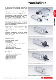
10. Ersatzteile/Spare/replacement parts<br />
15<br />
16<br />
2<br />
12<br />
10<br />
9<br />
13<br />
8<br />
4<br />
<strong>GN</strong> <strong>864</strong><br />
+ -<br />
18 19<br />
7<br />
21<br />
1<br />
11<br />
10<br />
3<br />
10<br />
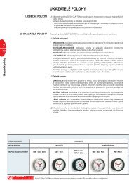
<strong>GN</strong> <strong>865</strong><br />
+ -<br />
17, 5<br />
14<br />
15<br />
2<br />
16<br />
14<br />
6, 17<br />
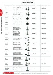
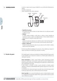
<strong>GN</strong> <strong>866</strong>.1<br />
17, 5 14 15<br />
+ -<br />
2<br />
16<br />
14<br />
6, 17<br />
Größe Kolb./Size piston Ø 20 Größe Kolb./Size piston Ø 32<br />
Pos. <strong>GN</strong> <strong>864</strong> <strong>GN</strong> <strong>865</strong> <strong>GN</strong> <strong>866</strong> <strong>GN</strong> <strong>866</strong>.1 <strong>GN</strong> <strong>864</strong> <strong>GN</strong> <strong>865</strong> <strong>GN</strong> <strong>866</strong> <strong>GN</strong> <strong>866</strong>.1<br />
1 <strong>864</strong>-1.1-B-20-01 <strong>864</strong>-1.1-B-32-01<br />
2<br />
<strong>864</strong>-1.2-B-<br />
20-02<br />
<strong>866</strong>-1.2-BC-<br />
20-02<br />
<strong>864</strong>-1.2-B-32-02<br />
3 <strong>864</strong>-1.3-B-20-04 <strong>864</strong>-1.3-B-32-04<br />
4 <strong>864</strong>-1.4-B-20-06 <strong>864</strong>-1.4-B-32-06<br />
5<br />
<strong>864</strong>-<br />
1.5-B-<br />
20-11/<br />
BL<br />
<strong>864</strong>-<br />
1.5-B-<br />
20-11/<br />
BI<br />
<strong>864</strong>-<br />
1.5-B-<br />
20-11/<br />
BC<br />
<strong>864</strong>-<br />
1.5-B-<br />
20-11/<br />
BE<br />
<strong>864</strong>-<br />
1.5-B-<br />
32-11/<br />
BL<br />
<strong>864</strong>-<br />
1.5-B-<br />
32-11/<br />
BI<br />
<strong>864</strong>-<br />
1.5-B-<br />
32-11/<br />
BC<br />
6 <strong>864</strong>-1.6-B-20-12 <strong>864</strong>-1.6-B-32-12<br />
7 <strong>864</strong>-1.7-P-4x28 <strong>864</strong>-1.7-P-6x36<br />
8 <strong>864</strong>-1.8-TA-M5x10 <strong>864</strong>-1.8-M8x12<br />
9<br />
10<br />
11<br />
12<br />
13<br />
14<br />
<strong>864</strong>-1.9-KJ-20<br />
<strong>864</strong>-1.9-KJ-32<br />
19<br />
<strong>864</strong>-<br />
1.5-B-<br />
32-11/<br />
BE<br />
15 <strong>864</strong>-1.14-KM-20 <strong>864</strong>-1.14-KMC-20 <strong>864</strong>-1.14-KM-32 <strong>864</strong>-1.14-KMC-32<br />
16<br />
17 <strong>864</strong>1.17-TAV-m4x8<br />
18 <strong>864</strong>-1.18-<br />
B-20-03<br />
19 -<br />
-<br />
<strong>865</strong>-1.19-<br />
B-20-10<br />
<strong>864</strong>-1.18-<br />
B-20-14<br />
-<br />
-<br />
<strong>866</strong>-1.19-<br />
B-20-10<br />
<strong>864</strong>-1.18-<br />
B-32-03<br />
-<br />
-<br />
<strong>865</strong>-1.19-<br />
B-32-10<br />
<strong>864</strong>-1.18-<br />
B-32-14<br />
-<br />
-<br />
<strong>866</strong>-1.19-<br />
B-32-22<br />
20 - - - - - - - -<br />
21 <strong>864</strong>-1.21-<br />
PF-20<br />
- - -<br />
<strong>864</strong>-1.21-<br />
PF-32<br />
- - -<br />
Größe Kolb./Size piston Ø 40 Größe Kolb./Size piston Ø 50<br />
Pos. <strong>GN</strong> <strong>864</strong> <strong>GN</strong> <strong>865</strong> <strong>GN</strong> <strong>866</strong> <strong>GN</strong> <strong>866</strong>.1 <strong>GN</strong> <strong>864</strong> <strong>GN</strong> <strong>865</strong><br />
1 <strong>864</strong>-1.1-B-40-01 <strong>864</strong>-1.1-B-50-01<br />
2 <strong>864</strong>-1.2-B-40-02 <strong>864</strong>-1.2-B-50-02<br />
3 <strong>864</strong>-1.3-B-40-04 <strong>864</strong>-1.3-B 50-04<br />
4 <strong>864</strong>-1.4-B-40-06 884-1.4 B-50-06<br />
5<br />
<strong>864</strong>-<br />
1.5-B-<br />
40-11/<br />
BL<br />
<strong>864</strong>-<br />
1.5-B-<br />
40-11/<br />
BI<br />
<strong>864</strong>-<br />
1.5-B-<br />
40-11/<br />
BC<br />
<strong>864</strong>-<br />
1.5-B-<br />
40-11/<br />
BE<br />
<strong>864</strong>-1.5-B-<br />
50-11/BL<br />
<strong>864</strong>-1.5-B-<br />
50-11/BI<br />
6 <strong>864</strong>-1.6-B-40-12 <strong>864</strong>-1.6-B-50-12<br />
7 <strong>864</strong>-1.7-P-8x45 <strong>864</strong>.1-1.7-P-10x60<br />
8 <strong>864</strong>-1.8-M10x16<br />
9<br />
10<br />
11<br />
12<br />
13<br />
14<br />
<strong>864</strong>-1.9-KJ-40<br />
<strong>864</strong>-1.9-KJ-50<br />
15 <strong>864</strong>-1.14-KM-40 <strong>864</strong>-1.14-KMC-40 <strong>864</strong>-1.14-KM-50<br />
16<br />
17 <strong>864</strong>1.17-TAV-m4x8<br />
18 <strong>864</strong>-1.18-<br />
B-40-03<br />
19 -<br />
-<br />
<strong>865</strong>-1.19-<br />
B-40-10<br />
<strong>864</strong>-1.18-<br />
B-40-14<br />
-<br />
- <strong>864</strong>-1.18-B-50-03 -<br />
<strong>866</strong>-1.1.9-<br />
B-40-22<br />
- <strong>865</strong>-1.19-B-50-10<br />
20 - - - - - -<br />
21 <strong>864</strong>-1.21-<br />
PF-40<br />
- - - 884-1.21-PF-50 -<br />
en<br />
Translation of the original operation instruction (de)<br />
1. Safety instructions<br />
These operating instructions for power clamps of series <strong>GN</strong> <strong>864</strong>/<strong>865</strong>/<strong>866</strong>/<strong>866</strong>.1<br />
are intended for construction engineers and project developers of plants and<br />
machinery and for installation and maintenance/service personnel.<br />
1.1 Definition of cautions<br />
Caution: Indicates a potentially hazardous situation. Failure to observe the<br />
safety provisions can result in personal injury or damage to property.<br />
1.2 General cautions<br />
Caution: These operating instructions must be used for all assembly,<br />
dismantling or repair work!<br />
Caution: When in operation, power clamps of series <strong>GN</strong> <strong>864</strong>/<strong>865</strong>/<strong>866</strong>/<strong>866</strong>.1<br />
must be fitted with external safety devices (protective guards, light barriers, etc.).<br />
Caution: When closed, the power clamp generates a high clamping force<br />
which, due to mechanical locking, is also kept up if the compressed air supply is<br />
disrupted.<br />
1.3 Intended use, range of application<br />
The pneumatically operated power clamps of series <strong>GN</strong> <strong>864</strong>/<strong>865</strong>/<strong>866</strong>/<strong>866</strong>.1 are<br />
designed for use in jigs and handling systems. They are used for clamping, holding,<br />
gripping and positioning workpieces.<br />
Caution: Before operating the power clamps (series <strong>GN</strong> <strong>864</strong>/<strong>865</strong>/<strong>866</strong>/<strong>866</strong>.1)<br />
make sure that the intended use with regard to the range of use (safety<br />
precautions, trained and qualified personnel, compressed air supply) is complied<br />
with.<br />
1.4 Product description<br />
The power clamps <strong>GN</strong> <strong>864</strong>/<strong>865</strong>/<strong>866</strong>/<strong>866</strong>.1 are made in the sizes 20, 32, 40 or 50.<br />
The size refers to the piston diameter of the driving pneumatic cylinder. The clamp<br />
consists of a pneumatic cylinder, a metal housing and various attachment options<br />
and one or two clamping arms.<br />
During clamping, the pneumatic cylinder acts as a servo unit on an integrated cam<br />
mechanism which triggers the swivel movement of the clamping arms. The rotary<br />
motion ends with a mechanical locking action. Operating and switching state can<br />
be displayed via external proximity switches.<br />
2. Safety<br />
Caution: Power clamps are not fitted with their own safety devices. Jamming<br />
and crushing hazard!<br />
If defective, the power clamps must not be operated. Maintenance and service<br />
work must be carried out with the machine at rest and without pressure applying.<br />
After completing maintenance and service work, all protection devices must be in<br />
refitted in proper working condition.<br />
3. Assembly and startup<br />
The units are installed or attached using cylindrical screws and guide bushes. The<br />
clamp can also be mounted directly to the cylinder via collar clamps. The mounting<br />
contact surfaces must be plane and clean. All screws and bolts must be tightened<br />
with the correct torque.<br />
The compressed air supply is connected to the power clamp using a suitable<br />
coupling. The connection marked (+) closes the clamp, the connection marked (-)<br />
opens the clamp.<br />
Caution: The power clamp has an integrated end position damper for the<br />
advance stroke, but not for the return stroke. This is why the permissible clamping<br />
arm torque must be maintained (see Table). If the recommended values for the<br />
maximum clamping arm weight are exceeded, an adjustable end position damper<br />
must be used.<br />
Type<br />
Cylinder ø<br />
Maximum allowable<br />
torque<br />
<strong>864</strong>/<strong>865</strong>/<strong>866</strong>/<strong>866</strong>.1 20 1,00 Nm<br />
<strong>864</strong>/<strong>865</strong>/<strong>866</strong>/<strong>866</strong>.1 32 1,25 Nm<br />
<strong>864</strong>/<strong>865</strong>/<strong>866</strong>/<strong>866</strong>.1 40 1,50 Nm<br />
<strong>864</strong>/<strong>865</strong> 50 3,00 Nm<br />
weight <strong>GN</strong> <strong>864</strong>-20-BI/BL<br />
(Kg)<br />
2<br />
1,5<br />
1<br />
0,5<br />
0<br />
50 75 100 125 150 175<br />
length (mm)<br />
weight <strong>GN</strong> <strong>864</strong>-40-BI/BL<br />
(Kg)<br />
3<br />
2,5<br />
2<br />
1,5<br />
1<br />
0,5<br />
0<br />
50 75 100 125 150 175<br />
length (mm)<br />
weight <strong>GN</strong> <strong>864</strong>-32-BI/BL<br />
(Kg)<br />
2,5<br />
2<br />
1,5<br />
1<br />
0,5<br />
0<br />
50 75 100 125 150 175<br />
length (mm)<br />
weight <strong>GN</strong> <strong>864</strong>-50-BI/BL<br />
(Kg)<br />
6<br />
5<br />
4<br />
3<br />
2<br />
1<br />
0<br />
50 75 100 125 150 175<br />
length (mm)<br />
4. Querying the operating and switching state<br />
An external proximity switch (inductive sensor <strong>GN</strong> 893.1/893.2/893.3) is provided<br />
for querying the operating and switching state. It is bolted to the side housing of the<br />
power clamp and the plug is connected to the power circuit.<br />
Operating the unit with an incorrect or an excessive voltage can cause short<br />
circuits and personal injuries. To ensure trouble-free operation, the maximum<br />
ambient temperature must not exceed 80°C. If the ambient temperature is outside<br />
these limits, a special sensor must be used.<br />
4.1 LED-Display<br />
green = Operating voltage, red = Switching state closed,<br />
yellow = Switching state open<br />
5. Setting the clamping force<br />
Caution: Fingers may be crunched or squeezed when setting the clamping<br />
arms. Do not reach into the clamping zone of the clamping arms while the clamp is<br />
being operated. If work is required at the clamping tool, the compressed air supply<br />
must first be disconnected.<br />
The clamping force is set via a special cam mechanism which, when the clamping<br />
position (0°) is reached, delivers the maximum clamping force. A self-locking<br />
mechanism of the clamp acts in this position. Once reached, the clamping force is<br />
also kept up if the pressure drops.<br />
5.1 Setting the clamping force <strong>GN</strong> <strong>864</strong><br />
<br />
<br />
<br />
1<br />
Positioning<br />
2<br />
Close clamp<br />
3<br />
Close pressure screws or place<br />
setting platelets in the moving<br />
arm until contact is made with the<br />
workpiece<br />
4<br />
Open clamp until end<br />
position is reached<br />
5<br />
Screw in pressure screws<br />
as shown in table or insert<br />
setting platelets<br />
Operating pressure 6 bar<br />
20 32 40 50<br />
Clamping<br />
Clam-<br />
Clam-<br />
Clam-<br />
Turn<br />
Setting ping<br />
Setting ping<br />
Setting ping<br />
Setting<br />
Turn<br />
Turn<br />
Turn<br />
platelet force platelet force platelet force platelet force<br />
(N)<br />
(N)<br />
(N)<br />
(N)<br />
0° 0 0 0° 0 0 0° 0 0 0° 0 0<br />
149° 0.60 ~ 81 222° 0.60 ~ 146 224° 0.60 ~ 281 262° 1,1 ~ 325<br />
192° 0.80 ~ 122 247° 0.80 ~ 219 274° 0.80 ~ 388 324° 1,3 ~ 488<br />
213° 1.00 ~ 162 296° 1.00 ~ 292 324° 1.00 ~ 496 401° 1,5 ~ 651<br />
5.2 Setting the clamping force <strong>GN</strong> <strong>866</strong><br />
1<br />
Fix the lower screws at a pre determined figures.<br />
Place the sheet to hold<br />
2<br />
Close the clamp with pressure or by hand until<br />
it reaches the top position<br />
3<br />
Bring both screws on the mobile arm over<br />
to the sheet until they contact it without pressure<br />
4<br />
Open the clamp with pressure or by hand<br />
until it gets the position of rest<br />
5<br />
Turn the screws an adjust them according to H<br />
or Turn Screws figures<br />
Operating pressure 6 bar<br />
20 32<br />
Turn<br />
H<br />
Clamping force<br />
H<br />
Clamping force<br />
Turn<br />
(mm) (N)<br />
(mm) (N)<br />
0° 0 0 0° 0 0<br />
236° 0,81 900 360° 1.50 1700<br />
230° 0,93 1030 420° 1.75 2050<br />
Once the clamp has been adjusted to the desired force depending on<br />
the minimum work pressure the non-reversibility should be checked<br />
according to the point (5.3 Self-Icoking).<br />
5.3 Self-locking<br />
After the desired clamping force has been set in accordance with the minimum<br />
working pressure (Table „Operating pressure“), check the self-locking mechanism<br />
of the clamp.<br />
a) Checking the bearing gap:<br />
<br />
<br />
self-locking acts if A = 0.5 +1<br />
0 mm<br />
b) Checking the cylinder position:<br />
<br />
<br />
with the value in the following table<br />
Size B +1 0<br />
20 5<br />
32 13<br />
40 18<br />
50 20<br />
6 Maintenance<br />
The clamps are fitted with low maintenance bearings and guides for use in large<br />
batch production. It is nonetheless necessary to protect the clamp from dirt and<br />
pollution. The maintenance interval depends on the ambient conditions and the<br />
frequency of use.<br />
6.1 Cleaning<br />
<br />
<br />
<br />
<br />
Cleaning the unit with a high-pressure cleaner, dry ice or similar can<br />
damage the clamp!<br />
If used under extreme ambient conditions (welding spatter, etching, high<br />
temperatures, etc.), in particular during arc welding, the clamp must be coated with<br />
a special agent (fluoropolymer).<br />
The <strong>GN</strong> <strong>865</strong>/<strong>866</strong>/<strong>866</strong>.1 power clamps are not suitable for use in arc welding.<br />
6.2 Compressed air<br />
We advise using conditioned (filtered) compressed air to prevent particles such as<br />
dust, oil or others damaging the inner components of the power clamps.<br />
If a compressed air system with oil lubrication is used, the oil must be mineralbased<br />
or synthetic to avoid incompatibility with the grease of the seals.<br />
6.3 Grease for seals<br />
The commercial grease AR 34-402 is used in all standard power clamps.<br />
For special-purpose designs and for high temperatures, Barrierta L55/1 is<br />
recommended. Both greases are brands of Klüber Lubrication. If you have any<br />
further questions, please contact the manufacturer directly.<br />
6.4 Operating pressure<br />
Caution: The operating pressure must not exceed 10 bar! The normal working<br />
pressure is 6 bar. This applies to all sizes.<br />
Unlocking the clamp<br />
If the clamping mechanism is situated in the above dead centre<br />
position, the clamp will retain its clamping force in spite of the<br />
pressure drop. The unit can be unlocked only by again connecting<br />
the compressed air supply or manually, with the piston rod of the<br />
clamp to be pressed down (see illustration).<br />
Caution risk of injury:<br />
If the clamp is unlocked manually, the clamping arm may open suddenly.<br />
For this reason, never reach into the swivel zone.<br />
7. Replacing the clamping arm<br />
Replace the clamping arms as shown below:<br />
1<br />
Dismantle both lateral covers<br />
3<br />
Push the shaft down to the end<br />
5<br />
Unscrew the headwith the help<br />
of two Allen screws<br />
2<br />
Take bearings & bolt out<br />
4<br />
Take the internal bushing<br />
out of the arm<br />
6<br />
Take the head and<br />
the cylinder bush out<br />
7<br />
Unscrew the piston & take it out<br />
9<br />
Replace the used guide<br />
with the new one<br />
The clamping arms are re-assembled in reverse order:<br />
10<br />
Replace the two seals of the head<br />
12<br />
Prepare the shaft, guide cylinder<br />
bush & piston according to the drawing<br />
14<br />
Screw the head in with the help<br />
of two Allen screws<br />
16<br />
Assemble the internal bushing of<br />
the arm with the help of the bolt<br />
18<br />
Put the Bakelite cover & sensor,<br />
or lateral cover, on the clamp<br />
20<br />
Put the lateral cover on the clamp<br />
8<br />
With the arm straight, push down with an<br />
Allen key to take the shaft & guide out<br />
11<br />
Place the piston & the cylinder bush<br />
according to the drawing<br />
13<br />
Approach the shaft to the arm and<br />
tighten the screw<br />
15<br />
Push the shaft up to the halfway<br />
of the oblong hole of the body<br />
17<br />
Lay the clamp down horizontally and<br />
place the shaft and bearings in it<br />
19<br />
Turn the clamp and place<br />
the bearing in<br />
8 Function test/Seal-tight test<br />
All power clamps of the series <strong>GN</strong> <strong>864</strong>/<strong>865</strong>/<strong>866</strong>/<strong>866</strong>.1 are subjected to a function<br />
and/or seal-tight test.<br />
The following tests are carried out for each power clamp:<br />
8.1 Function test<br />
To stabilise elastic assemblies, a maximum pressure (10 bar) is applied to the<br />
clamps, followed by operation over several cycles.<br />
8.2 Seal-tight test<br />
Working pressure (5 bar) is applied to the chambers of the clamp. The pressure<br />
drop must not be greater than 1.5 mbar over a period of 8 seconds.<br />
8.3 Friction test<br />
Minimum pressure is applied to the clamp over several cycles. No impairment of<br />
the function must occur. Undesired burrs or strains can so be identified.<br />
9. Warranty<br />
9.1 Duration<br />
The clamps listed in these operating instructions are warranted for a period of 12<br />
months from transfer of perils.<br />
9.2 Scope of the warranty<br />
The warranty covers all defective parts and components of the system and the<br />
necessary repairs.<br />
9.3 Limitation of warranty<br />
The following are excluded from the warranty:<br />
<br />
negligence, overload, unsupervised operation, pressure increase, defective<br />
installation or extreme causes.