LM-Torsionskupplungssystem, LM-Kupplungen LM Torsional ...
LM-Torsionskupplungssystem, LM-Kupplungen LM Torsional ...
LM-Torsionskupplungssystem, LM-Kupplungen LM Torsional ...

Erfolgreiche ePaper selbst erstellen
Machen Sie aus Ihren PDF Publikationen ein blätterbares Flipbook mit unserer einzigartigen Google optimierten e-Paper Software.
www.rajalovejoy.com<br />
32<br />
<strong>LM</strong>-<strong>Torsionskupplungssystem</strong>, <strong>LM</strong>-<strong>Kupplungen</strong><br />
<strong>LM</strong> <strong>Torsional</strong> Coupling system, <strong>LM</strong> Couplings<br />
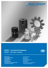
Die <strong>LM</strong>-Torsionskupplungen von Lovejoy sind speziell für Dieselmotorantriebe<br />
gefertigt. Die <strong>LM</strong>-<strong>Kupplungen</strong> haben insbesondere eine hohe Torsionselastizität<br />
und erlauben dem Motor den sicheren Antrieb einer relativ<br />
kleinen Trägheitslast, der über einen breiten Drehzahlbereich von der niedrigen<br />
Leerlaufdrehzahl bis zur vollen Motordrehzahl frei von schädlichen<br />
Torsionsresonanzen ist. Sie erfüllen diese Aufgabe indem sie die kritischen<br />
Drehzahlen weit genug unter die Leerlaufdrehzahl verlagern, um den vollen<br />
Betriebsdrehzahlbereich des Motors ohne Einschränkung zu ermöglichen.<br />
Im Wesentlichen erwirken diese hoch entwickelten <strong>Kupplungen</strong> durch die<br />
Reduzierung des Vibrationsdrehmoments auf einen sehr niedrigen Pegel<br />
einen abgeschwächten Beanspruchungspegel über den gesamten Antriebsstrang<br />
hinweg.<br />
Funktionsprinzip<br />
Ein kompaktes scheibenförmiges Elastomer-Element befindet sich im Herz<br />
der <strong>LM</strong>-Kupplung, das ihr diese hohe Torsionselastizität verleiht. Dieses Element<br />
ist an seinem Außendurchmesser mit geformten Zähnen ausgestattet.<br />
Diese Zähne bilden einen spielfreien Eingriff mit internen Zähnen an<br />
einem Aluminiumring, der die Kupplung vom Motorschwungrad antreibt.<br />
Diese Anordnung spannt das Elastomer vor, um seine Dämpfungs- und<br />
Belastungsaufnahmeleistung zu erhöhen und dadurch kann die Kupplung<br />
zusammengeschoben werden, was die "Blindmontage" innerhalb des<br />
Schwungradgehäuses ermöglicht. Es gibt der Kupplung auch die Fähigkeit,<br />
das Drehmoment etwas zu begrenzen, um den Antriebsstrang weiter zu<br />
schützen, da die Zähne während seltenen transienten Drehmomentspitzen<br />
(das 5- bis 6-fache des Nenndrehmoments) ihre Position verschieben<br />
können, ohne die Kupplung zu beschädigen. Wenn diese Spitzen häufig<br />
auftreten, blättern lediglich harmlose Gummiteilchen von der Kupplung ab,<br />
die keinen weiteren Schaden anrichten. Die Form des Elastomer-Elements<br />
verteilt die Betriebsbelastung gleichmäßig über seinen Arbeitsabschnitt<br />
und ermöglicht einen großen Verdrehwinkel (6 bis 12° bei nominalem Drehmoment,<br />
abhängig von der Größe) während die Beanspruchung minimiert<br />
wird. Dieses Merkmal platziert die <strong>LM</strong>-Kupplung inmitten der höchsten<br />
Torsionselastizitäten aller <strong>Kupplungen</strong>, die auf dem Markt erhältlich sind.<br />
Am dicken Mittelteil nahe der Nabe, sowie an den Zähnen werden die Beanspruchungen<br />
auf einen sehr niedrigen Pegel reduziert und bietet damit<br />
einen sehr zuverlässigen und robusten Antrieb.<br />
Größen<br />
Die <strong>LM</strong> Kupplung ist in 8 verschiedenen Größen erhältlich und deckt eine<br />
Drehmomentspanne von 250 bis 3800 Nm ab. Dieses weitreichende Angebot<br />
ermöglicht den Einsatz dieser Kupplung - von kleinen Einzylindermotoren<br />
bis hin zu den großen Mehrzylinderantriebsaggregaten mit einer<br />
Leistung bis zu 600 kW.<br />
Materialien<br />
• Elastomer-Element<br />
Temperaturbeständiger Naturgummi in unterschiedlichen Shore-Härtegraden,<br />
um den individuellen Anwendungsbedingungen zu entsprechen.<br />
Naturgummi kann bei -45 °C bis + 90 °C eingesetzt werden. Für ungewöhnlich<br />
hohe Umgebungstemperaturen, besonders in unbelüfteten<br />
Schwungradgehäusen, empfehlen wir den Einsatz unserer speziellen Silikonversion,<br />
ausgelegt für -45 °C bis +120 °C.<br />
• Außenring<br />
Hochwertige Aluminiumgusslegierung<br />
• Innere Nabe<br />
Stahl mit einer minimalen Zugfestigkeit von 600 N/mm 2<br />
The Lovejoy <strong>LM</strong> torsional couplings, are made especially for diesel engine drives.<br />
In particular, the <strong>LM</strong> couplings are highly elastic torsionally, allowing the engine<br />
to drive a relatively small inertia load safely free from damaging torsional<br />
resonance over a wide speed range from low idle RPM to full engine speed. They<br />
accomplish this task by shifting the critical speeds far enough below the idle<br />
speed to allow full use of the entire working speed range of the engine without<br />
limitation. In essence, these sophisticated couplings effect an attenuated level<br />
of stress throughout the whole drive train by reducing vibratory torque to a very<br />
low level.<br />
How they work<br />
A compact, disc-shaped elastomeric element lies at the heart of the <strong>LM</strong> coupling<br />
that gives it its high torsional elasticity. This element has molded cogs or teeth<br />
around its outside diameter. These cogs make a backlash-free engagement with<br />
internal cogs on an aluminum ring which drives it from the engine flywheel. This<br />
arrangement pre-loads the elastomer to increase its damping and load carrying<br />
capacity, and gives the coupling the ability to slip together and "blind assemble"<br />
inside the engine' s flywheel housing. It also gives the coupling some torque limiting<br />
ability to further protect the drive train, as the cogs are able to slip position<br />
during rare transient torque spikes (5 to 6 times rated torque) without damage<br />
to the coupling. If these spikes were to occur frequently, only harmless bits of<br />
rubber would shed from the coupling causing no further damage. The shape<br />
of the elastomeric element distributes operating stresses equally over its working<br />
section, allowing for a large angle of twist (6 to 12° at nominal torque load<br />
depending on size) while minimizing stress. This feature places the <strong>LM</strong> coupling<br />
amongst the highest torsional elasticities of all couplings available on the market.<br />
And at the thick center portion near the hub, as well as at the cogs, stresses<br />
are further reduced to a very low level, providing a very reliable and robust drive.<br />
We bond a steel ring to the center of the elastomeric element that assembles to<br />
a steel hub. The center of this hub is machined to fit the customer's driven shaft<br />
and is clamped solidly to the shaft at assembly by a tapered split hub, set screws<br />
or the L-Loc clamping system.<br />
Range of sizes<br />
<strong>LM</strong> couplings come in 8 different sizes covering a range of nominal torques from<br />
250 to 3800 Nm. This wide range of sizes make these couplings capable of handling<br />
applications driven from small singlecylinder engines on up to large multicylinder<br />
engines producing in excess of 600 kW.<br />
Materials<br />
• Elastomeric element<br />
Temperature-resistant natural rubber available in a variety of Shore hardnesses<br />
to suite individual application requirements. Our natural rubber is<br />
good for -45 °C to +90 °C. For unusually high ambient temperatures, especially<br />
in non-ventilated flywheel housings, we recommend using our special silicone<br />
version, rated for -45 °C to +120 °C.<br />
• Outer ring<br />
High-grade cast aluminum alloy.<br />
• Inner hub<br />
Steel with minimum tensile strength of 600 N/mm 2 .<br />
<strong>LM</strong>-<strong>Torsionskupplungssystem</strong><br />
<strong>LM</strong> Coupling
33<br />
<strong>LM</strong>-<strong>Torsionskupplungssystem</strong><br />
<strong>LM</strong> <strong>Torsional</strong> Coupling system<br />
Typische Anwendungen<br />
Typical applications<br />
• Verteilergetriebe für Multipumpenantriebe<br />
• Generatorsätze (2-Lagerausführung)<br />
• Lokomotiven<br />
• Hydraulikpumpen<br />
• Zentrifugalpumpen<br />
• Kompressoren<br />
• Schiffsantriebe<br />
• Splitter-gear multiple pump drives<br />
• Generator sets (2-bearing)<br />
• Locomotives<br />
• Hydraulic pumps<br />
• Centrifugal pumps<br />
• Compressors<br />
• Ship propulsion<br />
Merkmale der <strong>LM</strong>-Kupplung<br />
Features of the <strong>LM</strong> coupling<br />
Konstruktionsmerkmale<br />
Design features<br />
<strong>Torsional</strong> sehr weich und spielfrei, selbst nach vielen Betriebsstunden. Keine<br />
beweglichen Teile, die verschleißen oder Geräusche erzeugen. Keine Verschleißteile<br />
und keine Schmierung erforderlich.<br />
<strong>Torsional</strong>ly very soft. Backlash-free, even after long service hours. No moving<br />
parts to wear out or make noise. No wearing parts and no lubrication needed.<br />
Einfacher steckbarer Zusammenbau, ausgelegt für die Blindmontage innerhalb<br />
eines Schwungradgehäuses. Keine Befestigungsschrauben mit Durchgangsbohrungen.<br />
Fest sitzende Naben mit speziellem Konus, die jedoch<br />
ohne Spezialwerkzeug oder Abzieher demontiert werden können.<br />
Simple "plug-in" assembly designed for blind fitting inside a flywheel housing.<br />
No mounting bolts to access through holes. Special tapered hub grips firmly yet<br />
removes without special tools or pullers.<br />
Keine Axialkräfte bei der Drehmomentübertragung. Kompensiert Axial-, Parallel-<br />
und Winkelverlagerungen. Erlaubt freies Längsspiel.<br />
No axial forces generated by transmission of torque. Compensates for axial, parallel<br />
and angular misalignment. Permits free axial float.<br />
Eine große Auswahl an abdeckbaren Drehmomenten. Geeignet für<br />
Hochgeschwindigkeitszug-motoren. Standartflansche für SAE<br />
Schwungräder. Naben mit einer hohen Abdeckung des Bohrcodespektrums.<br />
Schlanke Form, kompaktes Design.<br />
Wide range of toque sizes. Suitable for high engine speeds. Standard input flanges<br />
for SAE flywheels. Large bore capacity hubs. Slim profile, compact design.<br />
Eine einzigartige Drehmomentbegrenzungseigenschaft liefert ein schnelles<br />
automatisches Abschalten des Motors, sollte die angetriebene Maschine blockieren<br />
oder ein Generatorsatz eine inkorrekte Synchronisation oder einen<br />
Kurzschluss erfahren.<br />
Unique torque limiting feature provides fast, automatic disconnect of the engine<br />
should the driven machinery lock up or a gen-set experience incorrect synchronization<br />
or short circuit.<br />
Die Torsionssteifheit der Kupplung ist über einfaches wechseln des elastischen<br />
Elementes, welches in verschiedenen Shorehärten (Shoreskala A)<br />
und Drehmomentabstufungen erhältlich ist, einstellbar.<br />
Coupling torsional stiffness is adjustable by simply changing the elastomeric<br />
elements, which are available in several Shore A hardness ratings and torque<br />
values.<br />
Spezielle Hochtemperatur-Gummimischung. Löcher in der Nabe und im Adapterflansch<br />
unterstützen die Luftstromkühlung.<br />
Special high-temperature rubber compound. Holes in hub and adapter flange<br />
promote flow-through air cooling.<br />
Lineare Torsionssteifheitsmerkmale (Gummi) bedeuten, dass durch die Belastung<br />
keine Verschiebung der Resonanzfrequenzen erfolgt.<br />
Linear torsional stiffness characteristic (rubber) means resonance frequencies<br />
are not shifted by the load.<br />
Eingesetztes Elastomer Element.<br />
Elastomeric working element.<br />
Vorteile<br />
Benefits<br />
• Schützt Maschinen vor Vibrations- und Stoßbelastungsschäden<br />
• Geräuschdämpfend für ruhigeren Maschinenlauf<br />
• Wartungsfrei<br />
• Zuverlässiger Betrieb<br />
• Lange Lebensdauer<br />
• Protects equipment from vibration and shock load damage<br />
• Noise silencing for quieter equipment running<br />
• Maintenance-free<br />
• Reliable service<br />
• Long life<br />
• Einfache und schnelle Montage<br />
• Installation is easy and fast<br />
• Verlängert die Lebensdauer der Lager und Dichtungen an angekuppelten<br />
Einheiten<br />
• Extends life of bearings and seals on coupled equipment<br />
• Vielfältige Lösungen für kleine, mittlere und große leistungsintensive<br />
Anwendungen.<br />
• Versatile solutions for small, medium or large horsepower applications<br />
• Schützt Motor und die maschinelle Einrichtung vor extremen Überbelastungsschäden<br />
• Protects engine and equipment from extreme overload damage<br />
• Einfache Frequenzabstimmung mit der Antriebseinheit.<br />
• Simple frequency tuning of the power train<br />
• Gute eigenleitende Hitzeableitung für verlängerte Lebensdauer<br />
• Good intrinsic heat dissipation for extended life<br />
• Ermöglicht die Leistungsfähigkeit von Generatorsätzen selbst bei Motorfehlzündungen<br />
• Allows gen-sets to perform even when engines misfire<br />
• Elektrische Isolation des Motors gegenüber der Abtriebseinheit<br />
• Electrically isolates engine from driven equipment
www.rajalovejoy.com<br />
34<br />
<strong>LM</strong>-Torsionskupplungen – Konstruktionstypen<br />
<strong>LM</strong> <strong>Torsional</strong> Coupling design types<br />
1. Typ SB - Größen von 240 bis 2400<br />
Die angetriebene innere Nabe besteht aus zwei Teilen: einem vulkanisierten<br />
Stahlring und der inneren, mit Konus versehenen Nabe. Diese zwei Teile<br />
sind miteinander verschraubt und das Drehmoment wird durch Reibung<br />
übertragen, die von axialen Schrauben erzeugt wird, mit denen die konische<br />
Nabe in das Element gezogen wird.<br />
1. Type SB sizes 240 to 2400<br />
The driven inner hub consists of two pieces: the vulcanized steel ring and the<br />
inner tapered hub. These two parts are bolted together and the torque is transmitted<br />
by the friction force created by the axial bolts, drawing the tapered hub<br />
into a mating taper in the element. This is a long tapered fit, but it can easily be<br />
disassembled if the coupling has to be removed. The vulcanized steel ring creates<br />
a very high inward pressure acting on the inner driven tapered hub. To utilize<br />
this pressure, the driven hub is slotted in an axial direction. This compresses<br />
the driven hub to provide a very strong backlash-free connection between the<br />
driven hub and driven shaft. This clamping effect can be used equally well on<br />
cylindrical shafts with keys or splined shafts.<br />
Typ SB<br />
Type SB<br />
Wellenverbindung<br />
Shaft lock<br />
2. Typ SC – Größen von 2800 bis 3500<br />
Ein innerer Ring aus Sphäroguss ist in das Elastomer-Element vulkanisiert.<br />
Dieser Flansch ist mit der inneren, mit Konus versehenen Nabe verschraubt.<br />
Abhängig von der Anordnung des Elastomer-Elements sind unter Verwendung<br />
der gleichen Komponenten zwei unterschiedlichen Längen möglich.<br />
Kurze Version: SCA<br />
Lange Version: SCB<br />
2. Type SC – sizes 2800 to 3500<br />
An inner ring made of spheroidal cast iron is vulcanized into the elastomeric<br />
element. This flange is bolted to the inner tapered hub. Depending upon the arrangement<br />
of the elastomeric element, two different lengths are possible utilizing<br />
the same components.<br />
Short Version: SCA<br />
Long Version: SCB<br />
Typ SCA<br />
Type SCA<br />
Typ SCB<br />
Type SCB<br />
3. Typen SBE und SCE – Spezielle Typen für die radiale Montage/<br />
Demontage (Radialausbautypen) Alle Größen<br />
Die Elastomer-Elemente können ohne die Kupplungswelle zu stören, schnell<br />
und leicht ausgewechselt werden, vorausgesetzt, dass das Schwungradgehäuse<br />
nicht zu weit vorsteht. Diese Versionen sind besonders vorteilhaft bei<br />
größeren Modellen und besonders dann, wenn die Nabe einen Festsitz hat.<br />
3. Types SBE and SCE – special radial assembly/disassembly<br />
Types (Drop-Out Types) All Sizes<br />
The elastomeric element can be changed quickly and easily without disturbing<br />
the coupling shaft, provided the flywheel housing does not protrude too much.<br />
These versions can be particularly advantageous on larger sizes, especially if the<br />
hub is interference fit.<br />
Typ SCE (montiert)<br />
Type SCE (assembled)<br />
Typ SCE (demontiert)<br />
Type SCE (disassembled)
35<br />
<strong>LM</strong>-Torsionskupplung – Auswahl<br />
<strong>LM</strong> <strong>Torsional</strong> Coupling selection<br />
Benutzen Sie die folgenden 3 Schritte in Verbindung mit den technischen<br />
Daten unserer Maßtabellen, die in den folgenden Abschnitten enthalten<br />
sind, um eine vorläufige Kupplungsauswahl zu treffen:<br />
1. Anwendungsdrehmoment<br />
Wählen Sie eine Kupplungsgröße mit einem Nenndrehmoment (T KN ) größer<br />
oder gleich dem Anwendungsdrehmoment (T) mit folgender Gleichung berechnet<br />
aus:<br />
T = kW * 9550/U/min<br />
vorausgesetzt<br />
T < T KN<br />
*S t1<br />
wobei S t1<br />
der in der Tabelle gefundene Temperaturfaktor für das nominale<br />
Drehmoment ist. Diese Zahl ist typischerweise mindestens 0,6 oder 0,7<br />
(für die typische Umgebungstemperatur von 60 bis 70 °C innerhalb des<br />
Schwungradgehäuses).<br />
2. SAE-Schwungradgröße<br />
Wählen Sie die entsprechende SAE J620 Flanschgröße passend zu Ihrem<br />
Schwungrad aus.<br />
3. Wellenmaße<br />
Stellen Sie sicher, dass der maximale Bohrungsdurchmesser der Kupplung<br />
das Maß Ihrer angetriebenen Welle aufnimmt. Die Nabenlänge der Kupplung<br />
kann, wenn erforderlich, gekürzt werden.<br />
Use the following 3 steps in conjunction with the technical data and dimension<br />
tables contained in the following sections to make the preliminary coupling selection:<br />
1. Application torque<br />
Select a coupling size with a nominal torque rating (T KN ) greater or equal to the<br />
application torque (T) calculated with the equation:<br />
T = kW * 9550/RPM<br />
provided<br />
T < T KN<br />
*S t1<br />
where S t1<br />
is the temperature factor for nominal torque found from the chart.<br />
This number will typically be at least .6 or .7 (for typical ambient temperature of<br />
at least 60 to 70°C inside the flywheel housing).<br />
2. SAE flywheel Ssize<br />
Select the appropriate SAE J620 flange size to match your flywheel.<br />
3. Shaft dimensions<br />
Make sure maximum bore capacity of coupling will accommodate the dimensions<br />
of your driven shaft. Coupling hub length can usually be shortened if necessary<br />
to fit into tight space envelopes.<br />
WICHTIG:<br />
Die endgültige Auswahl der Kupplungsgröße erfordert eine Verifizierung<br />
durch eine Torsionsvibrationsanalyse.<br />
Diese Analyse identifiziert kritische Drehzahlbereiche und stellt sicher, dass<br />
keine Bedingungen für exzessive dauernde oder kurzzeitige Resonanzen im<br />
normalen Betriebsdrehzahlenbereich des Systems vorhanden sind.<br />
<strong>LM</strong>-<strong>Kupplungen</strong> sind robust, zuverlässig und einzigartig in ihrer Fähigkeit,<br />
Torsionsvibrationsprobleme in bestimmten Anwendungen zu lösen. Wie<br />
jedoch bei allen Torsionskupplungen kann eine ungeeignete Kupplungsauswahl<br />
zu instabilen Bedingungen führen, welche die Kupplung und den<br />
Rest des Antriebsstrangs in Gefahr bringt. Falls erforderlich kann Lovejoy<br />
die Torsionsvibrationsanalyse für Sie durchführen. Füllen Sie einfach das Arbeitsblatt<br />
auf Seite 10 aus und faxen Sie es uns.<br />
Weitere Details hinsichtlich der auf dieser Analyse basierenden Kupplungsauswahl<br />
finden Sie auf Seite 8 und 9.<br />
IMPORTANT:<br />
Final selection of coupling size requires verification by torsional vibration<br />
analysis.<br />
This analysis will identify the location of critical speeds and confirm the absence<br />
of excessive steady-state and peak resonance conditions over the normal operating<br />
cycle of the equipment.<br />
<strong>LM</strong> couplings are robust, reliable and unique in their ability to solve torsional<br />
vibration problems in certain applications. But as with all torsional couplings,<br />
inappropriate coupling selection can lead to unstable conditions that place the<br />
coupling as well as the rest of the drive train at danger. Lovejoy can perform the<br />
torsional vibration analysis for you if necessary. Simply complete the worksheet<br />
found on page 10 and fax it to us.<br />
You can find more details regarding coupling selection based on this analysis<br />
on pages 8 and 9.
www.rajalovejoy.com<br />
36<br />
<strong>LM</strong>-Torsionskupplung – Technische Daten – Naturgummi<br />
<strong>LM</strong> <strong>Torsional</strong> Coupling – technical data – natural rubber<br />
Kupplung<br />
Größe<br />
Coupling<br />
size<br />
Shore<br />
Härte<br />
Hardness<br />
(Durometer)<br />
SHORE A<br />
NENN-<br />
Drehmoment<br />
NOM torque<br />
MAX<br />
Drehmoment<br />
MAX torque<br />
*Ständiges<br />
Vibrations-<br />
Drehmoment<br />
*CONT<br />
vibratory<br />
torque<br />
Zulässiger<br />
Leistungs-<br />
Verlust<br />
Allowable<br />
power<br />
loss<br />
**Dynamische<br />
Torsions-<br />
Steifheit<br />
**Dynamic<br />
torsional<br />
stiffness<br />
Flansch Größe<br />
Flange size<br />
SAE J 620<br />
MAX. Drehzahl<br />
MAX speed<br />
Massenträgheitsmoment<br />
Mass moment of inertia<br />
***Primär<br />
***Primary<br />
Sekundär<br />
Secondary<br />
T KN<br />
T Kmax<br />
T KW<br />
P KV<br />
C Tdyn<br />
Schwungrad<br />
M max<br />
J1 J2<br />
(Nm) (Nm) (Nm) (W) (Nm/rad) Flywheel (U/min) (kgm 2 ) (kgm 2 )<br />
Kupplung<br />
Größe<br />
Coupling<br />
size<br />
50 250 500 100 925 8 4000 0.0208 0.0038<br />
<strong>LM</strong>240 60 300 600 120 37 1400<br />
<strong>LM</strong>240<br />
70 350 750 140 2250<br />
10 3600 0.0313 0.0038<br />
50 400 800 160 1600<br />
<strong>LM</strong>400 60 500 1000 200 62 2500 10 3600 0.0373 0.0114 <strong>LM</strong>400<br />
70 550 1100 220 4000<br />
50 700 1400 280 2800 10 3600 0.0599 0.0296<br />
<strong>LM</strong>800 60 850 1700 340 105 4200 11½ 3500 0.0732 0.0296 <strong>LM</strong>800<br />
70 950 2000 380 6800 14 3000 0.1378 0.0295<br />
50 1000 2000 400 150 4500 11½ 3500 0.0768 0.0456<br />
<strong>LM</strong>1200 60 1200 2400 480 150 7000<br />
<strong>LM</strong>1200<br />
70 1300 3000 520 150 11700<br />
14 3000 0.01432 0.0456<br />
<strong>LM</strong>1600<br />
50 1450 2900 580 6000 11½ 3200 0.224 0.078<br />
14 3000 0.197 0.078<br />
60 1800 3600 720 220 9000<br />
16 2500 0.274 0.078<br />
70 2000 4000 800 15000 18 2300 0.3855 0.078<br />
<strong>LM</strong>1600<br />
50 2000 4000 800 10000 14 3000 0.213 0.153<br />
<strong>LM</strong>2400 60 2500 5000 1000 300 15000 16 2500 0.29 0.153 <strong>LM</strong>2400<br />
70 2800 6000 1120 25000 18 2300 0.4015 0.153<br />
50 2800 6000 1120 25000 14 3000 0.2836 0.2257<br />
<strong>LM</strong>2800 60 3000 7500 1200 360 37500 16 2500 0.3158 0.02257 <strong>LM</strong>2800<br />
70 3200 8000 1280 63000 18 2300 0.4271 0.2257<br />
50 3200 6500 1280 16000 14 3000 0.2836 0.2295<br />
<strong>LM</strong>3500 60 3500 8000 1400 450 24000 16 2500 0.4388 0.2295 <strong>LM</strong>3500<br />
70 3800 8500 1520 38000 18 2300 0.5873 0.2295<br />
* Bei 10 Hz.<br />
** Konstanter Wert bei Naturgummi wegen der linearen Charakteristik<br />
*** Primär bedeutet die Schwungradseite der Kupplung<br />
* At 10 Hz.<br />
** Constant value for natural rubber because of linear characteristic<br />
*** Primary means the flywheel side of the coupling<br />
Frequenzfaktor S f Frequency factor S f<br />
f in H z<br />
10<br />
S f 1 √f/10<br />
Temperaturfaktor S t1 Temperature factor S t1<br />
T < T KN * S t1<br />
Resonanzfaktor V R<br />
Relativer Dämpfungsfaktor Ψ<br />
Resonance factor V R<br />
Relative damping factor Ψ<br />
Gummi Rubber<br />
S t1<br />
Grad Celsius<br />
Degrees C<br />
Naturgummi (NR)<br />
Natural Rubber (NR)<br />
f in H z<br />
V R<br />
Ψ<br />
35 - 40 12 0.52<br />
50 6.0 1.05<br />
60 5.7 1.10<br />
70 5.5 1.15<br />
Temperaturfaktor St2 für ständig. Vibrationsmoment<br />
TKW und zuläss. Leistungs-Verlust PKV<br />
Temperature factor S t2 for cont. vibr. torque T KW and<br />
allowable power loss P KV<br />
P V < P KV * St2<br />
T W < T KW * St2 * (1/S f )<br />
TKW<br />
Gummi Rubber<br />
S t2<br />
PKV<br />
Grad Celsius<br />
Degrees C
37<br />
<strong>LM</strong>-Torsionskupplungen – Technische Daten – Silikon (50 Shore A)<br />
<strong>LM</strong> <strong>Torsional</strong> Coupling technical data – Silicone (50 Shore A)<br />
Kupplung<br />
Größe<br />
Coupling<br />
size<br />
Nenn-<br />
Drehmoment<br />
Auslegung<br />
Nom. torque<br />
rating<br />
*Max.<br />
Drehmoment 1<br />
*Max. torque 1<br />
**Max.<br />
Drehmoment 2<br />
**Max. torque 2<br />
Ständiges<br />
Vibrations-<br />
Drehmoment<br />
Continuous<br />
vibratory<br />
torque<br />
Zulässiger<br />
Leistungs-<br />
Verlust<br />
Allowable<br />
power<br />
loss<br />
T KN<br />
T Kmax1<br />
T Kmax2<br />
T KW<br />
P KV<br />
*** Dynamische Torsionssteife<br />
*** Dynamic torsional stiffness<br />
C tdyn<br />
(Nm/rad)<br />
(Nm) (Nm) (Nm) (Nm) (W) 10 % T KN<br />
25 % T KN<br />
50 % T KN<br />
75 % T KN<br />
100 % T KN<br />
Ψ<br />
<strong>LM</strong>800 700 1050 1400 280 105 2200 2400 2800 3500 4600<br />
<strong>LM</strong>1200 1000 1500 2000 400 150 3600 3900 4500 5600 7400<br />
<strong>LM</strong>1600 1450 2200 2900 580 220 4800 5200 6000 7500 9900<br />
<strong>LM</strong>2400 2000 3000 4000 800 300 8000 8700 10000 12500 16500<br />
<strong>LM</strong>2800 2800 4200 5600 1120 360 21000 2300 25000 32500 42500<br />
<strong>LM</strong>3500 3200 4800 6400 1280 450 12800 13900 16000 20000 26500<br />
Relative<br />
Dämpfung<br />
Relative<br />
damping<br />
1.15<br />
* T max1 zeigt den maximal zulässigen Wert für transiente Drehmomentspitzen während dem normalen<br />
Arbeitszyklus, wie beispielsweise bei der Beschleunigung durch eine Resonanz während<br />
dem Starten und Stoppen oder Kuppeln.<br />
** T max2 repräsentiert das absolute, maximal zulässige Spitzendrehmoment bei seltenen Anlässen,<br />
wie einem Kurzschluss oder einer falscher Synchronisation an einem Generatorsatz.<br />
*** Das Silikonmaterial erzeugt belastungsabhängig eine progressive Steifheits-Charakteristik. Diese<br />
Werte haben eine Toleranz von ±15 %.<br />
* T max1 indicates the maximum allowable value for transient torque spikes during the normal work<br />
cycle, for example, from accelerating through a resonance during starting and stopping or clutching.<br />
** T max2 represents the absolute maximum peak torque allowable during rare occasions such as during<br />
a short circuit of a gen-set or incorrect synchronization.<br />
*** The silicone material creates a progressive stiffness characteristic dependent on load. These values<br />
have tolerance of + or -15 %.<br />
Temperaturfaktor S t SI für ständiges Vibrations-Drehmoment T KW und zulässiger Leistungsverlust P KV<br />
Temperature factor S t 2SI for cont. vibr. torque T KW and allowable power loss P KV<br />
P V < P KV * S t2 SI<br />
T W < T KW * S t2 SI * (1/S f )<br />
TKW<br />
Silikon Silicone<br />
S t 2SI<br />
PKV<br />
Grad Celsius<br />
Degrees C
www.rajalovejoy.com<br />
38<br />
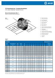
<strong>LM</strong>-<strong>Torsionskupplungssystem</strong> – Abmessungen<br />
<strong>LM</strong> <strong>Torsional</strong> Coupling dimensions<br />
240 - 2400 SB 2800 - 3500 SCA 2800 - 3500 SCB<br />
Standardtypen<br />
Standard types<br />
Kupplung<br />
Größe<br />
Coupling<br />
size<br />
SAE J620<br />
A C*<br />
d1 (Bohrung/bore)<br />
MIN<br />
MAX<br />
Abmessungen Dimensions (mm)<br />
d 3<br />
D B<br />
E L L 1<br />
N 1<br />
Gewicht<br />
Weight<br />
(kg)<br />
Bestell-Nr.<br />
Order code<br />
240 SB1 8 46 75 ± 9 15 50 262 50 27 75 60 73 6.1 <strong>LM</strong> - 240 - SB1 -**- 8<br />
240 SB1 10 46 75 ± 9 15 50 225 50 27 75 60 73 6.5 <strong>LM</strong> - 240 - SB1 -**- 10<br />
400 SB1 10 45 75 ± 7 20 60 313 61 25 80 65 90 8.6 <strong>LM</strong> - 400 - SB1 -**- 10<br />
800SB1 10 50 82±2 20 70 316 71 18 84 66 107 11.1 <strong>LM</strong> - 800 - SB1 -**- 10<br />
800 SB1 11½ 39 71 ± 3 20 70 351 71 18 84 66 107 10.1 <strong>LM</strong> - 800 - SB1 -**- 11<br />
800 SB1 14 46 74 ± 6 20 70 318 71 18 84 66 107 11.5 <strong>LM</strong> - 800 - SB1 -**- 14<br />
1200 SB1 11½ 39 65 ± 4 20 70 351 71 18 84 66 107 14.5 <strong>LM</strong> - 1200 - SB1 -**- 11L<br />
1200 SB1 14 46 74 ± 6 20 70 351 71 18 84 66 107 16.4 <strong>LM</strong> - 1200 - SB1 -**- 14<br />
1600 SB1 14 61 97 ± 11 30 105 465 106 26 106 85 150 22.5 <strong>LM</strong> - 1600 - SB1 -**- 14<br />
1600 S81 16 61 97 ± 11 30 105 417 106 26 106 85 150 23.8 <strong>LM</strong> - 1600 - SB1 -**- 16<br />
1600 SB1 18 61 97 ± 11 30 105 417 106 26 106 85 150 25.3 <strong>LM</strong> - 1600 - SB1 - **- 18<br />
2400 SB1 14 61 97 ± 6 30 105 465 106 26 106 85 150 31.1 <strong>LM</strong> - 2400 - SB1 -**- 14<br />
2400 SB1 16 61 97 ± 6 30 105 417 106 26 106 85 150 32.4 <strong>LM</strong> - 2400 - SB1 -**- 16<br />
2400 SB1 18 61 97 ± 6 30 105 417 106 26 106 85 150 33.9 <strong>LM</strong> - 2400 - SB1 -**- 18<br />
2800 SCA 1 14 61 93 ± 4 35 110 465 – 34 – 105 162 31.5 <strong>LM</strong> - 2800 - SCA1 -**- 14<br />
2800 SCB 1 14 61 135 ± 4 35 110 465 – 76 131 105 162 31.5 <strong>LM</strong> - 2800 - SCB1 -**- 14<br />
2800 SCA 1 16 61 93 ± 4 35 110 417 – 34 – 105 162 32.8 <strong>LM</strong> - 2800 - SCA1 -**- 16<br />
2800 SCB 1 16 61 135 ± 4 35 110 417 – 76 131 105 162 32.8 <strong>LM</strong> - 2800 - SCB1 -**- 16<br />
2800 SCA 1 18 61 93 ± 4 35 110 417 – 34 – 105 162 34.3 <strong>LM</strong> - 2800 - SCA1 - ** - 18<br />
2800 SCB 1 18 61 135 ± 4 35 110 417 – 76 126 105 162 34.3 <strong>LM</strong> - 2800 - SCB1 - **- 18<br />
3500 SCA 1 14 70 100 ± 8 35 110 465 – 25 – 105 162 33.9 <strong>LM</strong> - 3500 - SCA1 -**- 14<br />
3500 SCB 1 14 70 135 ± 8 6 110 465 – 60 140 105 162 33.9 <strong>LM</strong> - 3500 - SCB1 -**- 14<br />
3500 SCA 1 16 70 100 ± 8 35 110 465 – 25 – 105 162 36.6 <strong>LM</strong> - 3500 - SCA1 -**- 16<br />
3500 SCB 1 16 70 135 ± 8 35 110 465 – 60 140 105 162 36.6 <strong>LM</strong> - 3500 - SCB1 -**- 16<br />
3500 SCA 1 18 70 100 ± 8 35 110 465 – 25 – 105 162 38.5 <strong>LM</strong> - 3500 - SCA1 -**- 18<br />
3500 SCB 1 18 70 135 ± 8 35 110 465 – 60 140 105 162 38.5 <strong>LM</strong> - 3500 - SCB1 -**- 18<br />
* Die <strong>LM</strong>-Kupplung ist auf die axiale Länge bezogen sehr anpassbar. Das Gummielement kann<br />
innerhalb der für diese Abmessung aufgeführten Grenzen näher zur oder weiter weg von<br />
der Schwungscheibe positioniert werden, wobei der vollständige Eingriff mit dem äußeren<br />
Antriebsring erhalten bleibt. Auch die Nabenlänge L 1 ist mit entsprechenden Änderungen bis zu<br />
Montagelänge C einstellbar.<br />
** Geben Sie hier den Shore-Härtegrad des Gummielements an.<br />
* The <strong>LM</strong> coupling is very adaptable with regard to axial length. The rubber element can be positioned<br />
closer to or farther from the flywheel within the limits shown for this dimension, while maintaining full<br />
engagement with the outer drive ring. Hub length L 1 is adjustable as well with corresponding changes<br />
to mounting length dimension C.<br />
** Indicate Shore hardness for rubber element here.<br />
SAE-Schwungradabmessungen*<br />
SAE flywheel dimensions*<br />
SAE Größe<br />
SAE size<br />
Führung<br />
Pilot<br />
Schrauben-<br />
Kreis<br />
Bolt circle<br />
Durchg.-Löcher Thru holes<br />
Anzahl Number<br />
*SAE J620<br />
Größe Size<br />
D A<br />
(mm) D T<br />
(mm) Z S (mm)<br />
6-1/2 215.9 200.0 6 x 60° 9<br />
7-1/2 241.3 222.3 8 x 45° 9<br />
8 263.5 244.5 6 x 60° 11<br />
10 314.3 295.3 8 x 45° 11<br />
11-1/2 352.4 333.4 8 x 45° 11<br />
14 466.7 438.2 8 x 45° 13<br />
16 517.5 489.0 8 x 45° 13<br />
18 571.5 542.9 6 x 60° 17<br />
21 673.1 641.4 12 x 30° 17<br />
24 733.4 692.2 12 x 30° 19<br />
SAE-Pumpenkeilwellen*<br />
SAE pump splines*<br />
SAE Code<br />
Anzahl der Zähne<br />
Number of teeth<br />
Keil-Abstand<br />
Spline pitch<br />
* SAE J744<br />
Haupt-Durchmesser<br />
Major diameter<br />
A-A 9 20/40 12.7 mm<br />
A 9 16/32 15.9 mm<br />
B 13 16/32 22.2 mm<br />
B-B 15 16/32 25.4 mm<br />
C 14 12/24 31.8 mm<br />
C-C 17 12/24 38.1 mm<br />
D 13 8/16 44.5 mm<br />
E 13 8/16 44.5 mm<br />
F 15 8/16 50.8 mm