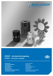
FTC Reifenkupplung â Standard Modellreihe FTC ... - RAJA-Lovejoy
FTC Reifenkupplung â Standard Modellreihe FTC ... - RAJA-Lovejoy
FTC Reifenkupplung â Standard Modellreihe FTC ... - RAJA-Lovejoy
Sie wollen auch ein ePaper? Erhöhen Sie die Reichweite Ihrer Titel.
YUMPU macht aus Druck-PDFs automatisch weboptimierte ePaper, die Google liebt.
1<br />
<strong>FTC</strong> <strong>Reifenkupplung</strong> – <strong>Standard</strong> <strong>Modellreihe</strong><br />
<strong>FTC</strong> rubber coupling – <strong>Standard</strong> Series<br />
Mit zwei <strong>Standard</strong>naben (Abb. 1)<br />
With two <strong>Standard</strong> Hubs (drawing 1)<br />
Abb. 1<br />
drawing 1<br />
A - Ø der Flanschnabe<br />
A - Ø Flange of the Hub<br />
B - Ø vom Nabenteil<br />
B - Ø Neck of the Hub<br />
C - Ø max. Bohrung<br />
C - Ø Max. bore<br />
D - Ø min. Bohrung<br />
D - Ø Min. bore<br />
E - Breite des elastischen Elements<br />
E - Width of the Flexible Element<br />
F - Nabenlänge<br />
F - Length of the Hub<br />
G - Länge der elastischen Kupplung<br />
G - Length of the Flexible Coupling<br />
H - Ø elastisches Element<br />
H - Ø Flexible Element<br />
L - Schraube<br />
L - Screw<br />
Tabelle 1<br />
Table 1<br />
<strong>Standard</strong>nabe<br />
<strong>Standard</strong> Hub<br />
Metrische Sechskantschrauben<br />
Metric Hex Cap Screws<br />
Modell<br />
Model<br />
Nominales Drehmoment<br />
Nominal Torque<br />
Torsion<br />
Torsion<br />
Gewicht (1)<br />
Weight<br />
Gd2<br />
Abmessung<br />
Dimension<br />
Nm (°) kg kg m 2 A B C max D min E F G H N. (mm)<br />
A-20 38 2 1.05 0.0017 74 36 20 10 30 25 80 95 12 6 x 1 x 20<br />
A-25 56 5 1.09 0.0018 74 36 23 10 30 25 80 95 12 6 x 1 x 20<br />
A-30 82 2 2.40 0.0094 96 49 30 10 40 35 110 127 16 8 x 1.25 x 25<br />
A-35 113 4 2.65 0.0098 96 49 32 10 40 35 110 127 16 8 x 1.25 x 25<br />
A-45 200 3 5.00 0.0382 127 70 40 15 50 45 140 167 20 8 x 1.25 x 25<br />
A-50 420 6 5.32 0.0402 127 70 46 15 50 45 140 167 20 8 x 1.25 x 25<br />
A-60 620 5 12.50 0.1065 169 100 55 25 65 60 185 224 24 10 x 1.50 x 35<br />
A-70 1170 9 13.30 0.1593 169 100 65 25 65 60 185 224 24 10 x 1.50 x 35<br />
A-80 1550 5 24.90 0.594 218 116 75 30 90 80 250 302 20 12 x 1.75 x 45<br />
A-90 2170 6 26.00 0.639 218 116 85 30 90 80 250 302 20 12 x 1.75 x 45<br />
A-95 2380 4 34.90 0.912 235 138 90 40 90 80 250 330 24 12 x 1.75 x 45<br />
A-105 3130 8 44.00 0.982 235 138 100 40 90 80 250 330 24 12 x 1.75 x 45<br />
A-120/90<br />
4940 5 68.60 2.90 297 150 90 45 120 100 320 403<br />
16 x 2 x 60<br />
A-120/120<br />
86.00 3.80<br />
195 120 45<br />
130 380<br />
20<br />
A-140/100<br />
A-140/140<br />
8500 9 87.00<br />
94.00<br />
3.05<br />
3.82<br />
297 150<br />
195<br />
100<br />
140<br />
45<br />
45<br />
120 100<br />
130<br />
320<br />
380<br />
403 20 16 x 2 x 60<br />
A-170/70<br />
A-170/130<br />
A-170/170<br />
A-200/90<br />
A-200/140<br />
A-200/200<br />
A-240/150<br />
A-240/200<br />
A-240/240<br />
A-300/150<br />
A-300/200<br />
A-300/250<br />
A-300/300<br />
A-350/200<br />
A-350/250<br />
A-350/350<br />
A-400/250<br />
A-400/400<br />
14630 7<br />
170.20<br />
211.80<br />
242.80<br />
192.60<br />
25190 11 202.40<br />
276.80<br />
364.70<br />
43060 4<br />
447.40<br />
633.60<br />
370.00<br />
86120<br />
450.00<br />
10 640.00<br />
695.00<br />
1049.00<br />
118750 6 1211.00<br />
2237.00<br />
168750 10 1219.00<br />
2245.00<br />
12.22<br />
13.75<br />
17.65<br />
13.30<br />
13.75<br />
19.20<br />
51.50<br />
55.35<br />
84.50<br />
50.70<br />
54.50<br />
69.40<br />
83.70<br />
435.20<br />
466.40<br />
691.00<br />
459.20<br />
697.00<br />
150<br />
436 236<br />
276<br />
186<br />
436 200<br />
276<br />
225<br />
535 290<br />
390<br />
225<br />
290<br />
535 350<br />
390<br />
290<br />
820 350<br />
600<br />
820 350<br />
600<br />
70<br />
130<br />
170<br />
90<br />
140<br />
200<br />
150<br />
200<br />
240<br />
150<br />
200<br />
250<br />
300<br />
200<br />
250<br />
350<br />
250<br />
400<br />
30<br />
70<br />
120<br />
40<br />
70<br />
120<br />
100<br />
100<br />
100<br />
110<br />
100<br />
100<br />
100<br />
120<br />
120<br />
120<br />
120<br />
120<br />
80<br />
185 130<br />
180<br />
100<br />
185 130<br />
180<br />
160<br />
236 180<br />
275<br />
160<br />
200<br />
236 275<br />
275<br />
200<br />
335 275<br />
375<br />
335 275<br />
375<br />
345<br />
445<br />
545<br />
385<br />
445<br />
545<br />
556<br />
596<br />
786<br />
556<br />
636<br />
786<br />
786<br />
735<br />
885<br />
1085<br />
885<br />
1085<br />
550 24 20 x 2.50 x 75<br />
550 24 20 x 2.50 x 75<br />
740<br />
740<br />
1130<br />
1130<br />
Die Angaben in diesem Katalog können ohne vorherige Mitteilung geändert werden<br />
The information displayed in this catalog is subject to modifications without warning.
www.rajalovejoy.com 2<br />
Elastische Kupplungen – <strong>Modellreihe</strong> für hohe Drehmomente – Sonderausführungen<br />
Flexible Couplings for High Torque Transmissions – Special Versions<br />
Mit 1 <strong>Standard</strong>nabe und 1 integrierten Nabe (design 2)<br />
With one <strong>Standard</strong> Hub and one Integral Hub (design 2)<br />
Abb. 4<br />
drawing 4<br />
I<br />
J<br />
- Ø max. Bohrung<br />
Ø Max. bore<br />
- Ø Nabenteil<br />
Ø Neck of the Hub<br />
K - Schraube<br />
Screw<br />
Tabelle 4<br />
Table 4<br />
Integrierte Nabe<br />
Integral Hub<br />
Größe<br />
Size<br />
A-20<br />
A-25<br />
A-30<br />
A-35<br />
A-45<br />
A-50<br />
A-60<br />
A-70<br />
A-80<br />
A-90<br />
A-95<br />
A-105<br />
I J K<br />
Metrische Schraubenfassung Metric Socket<br />
Innensechskantschrauben Head Cap Screws<br />
Abmessung<br />
Dimension<br />
Integrierte Nabe<br />
Integral Hub<br />
Größe<br />
Size<br />
I J K<br />
Metrisches Gewinde Metric Socket<br />
Innensechskantschrauben Head Cap Screws<br />
Abmessung<br />
Dimension<br />
max mm max mm<br />
30<br />
30<br />
44<br />
44<br />
60<br />
60<br />
90<br />
90<br />
100<br />
100<br />
125<br />
125<br />
66<br />
66<br />
86<br />
86<br />
110<br />
110<br />
150<br />
150<br />
180<br />
180<br />
198<br />
198<br />
6<br />
6<br />
8<br />
8<br />
10<br />
10<br />
12<br />
12<br />
10<br />
10<br />
12<br />
12<br />
6 x 1 x 30<br />
6 x 1 x 30<br />
8 x 1.25 x 40<br />
8 x 1.25 x 40<br />
8 x 1.25 x 50<br />
8 x 1.25 x 50<br />
10 x 1.50 x 65<br />
10 x 1.50 x 65<br />
12 x 1.75 x 95<br />
12 x 1.75 x 95<br />
12 x 1.75 x 95<br />
12 x 1.75 x 95<br />
A-120<br />
A-140<br />
A-170<br />
A-200<br />
A-240<br />
A-300<br />
A-350<br />
A-400<br />
170<br />
170<br />
250<br />
250<br />
*<br />
*<br />
*<br />
*<br />
*<br />
*<br />
*<br />
*<br />
*<br />
*<br />
*<br />
*<br />
10<br />
10<br />
12<br />
12<br />
30<br />
30<br />
30<br />
30<br />
16 x 2 x 150<br />
16 x 2 x 150<br />
20 x 2.5 x 200<br />
20 x 2.5 x 200<br />
Integrierte Naben können eingesetzt werden<br />
wenn die Wellendurchmesser größer<br />
sind als die in Tabelle 2 angegeben.<br />
Die Baugruppe kann je nach Anwendung<br />
mit einem oder zwei integrierten Naben<br />
eingesetzt werden.<br />
Integral hubs can be used when the shaft<br />
diameter is greater than the ones listed in<br />
Table 2.<br />
The assembly can be used with one or two<br />
integral hubs according to the applications<br />
needs.<br />
Bauformen<br />
Type of Assembly<br />
Mit Zwischenstück Bauform (ES)<br />
With spacer (ES)<br />
Alle verschiedenen Kupplungsmodelle können mit einem Zwischenstück ausgerüstet werden.<br />
Dies erleichtert den radialen Ausbau, z.B. bei Pumpenanwendungen. In diesen Fällen,<br />
bitte den Wellenabstand „L“ angeben!<br />
All the different coupling versions can be outfitted with a spacer, which facilitates the disassembling,<br />
which is common in pump applications (Back pull-out).<br />
For this request, please indicate the distances between the shaft points “L”.<br />
Abb. 5<br />
drawing 5<br />
Tabelle 5<br />
Table 5<br />
Modell<br />
Model<br />
ES 75 ES 100 ES 140 ES 180<br />
A-20/25 * * *<br />
A-30/35 * * *<br />
A-45/50 * * *<br />
Modell<br />
Model<br />
ES 140 ES 180 ES 215 ES 250<br />
A-60/70 * * *<br />
A-80/90 * * *<br />
A-95/105 * * *
3<br />
Elastische Kupplungen – <strong>Modellreihe</strong> für hohe Drehmomente – Sonderausführungenn<br />
Flexible Couplings for High Torque Transmissions – Special Versions<br />
Hohe Umdrehungsgeschwindigkeiten (CE)<br />
High speeds (CE)<br />
Für Anwendungen bei denen die Umdrehungsgeschwindigkeiten außerhalb der Tabellen-Parameter<br />
liegen, müssen die Wellen dynamisch ausgewuchtet und ausgerichtet sein und mit angepassten<br />
Naben betrieben werden.<br />
Bei dieser Anfrage, bitte die Umdrehungsgeschwindigkeit (U/min) angeben.<br />
Abb. 6<br />
drawing 6<br />
For applications where the speeds fall outside of the parameters in the table, the shafts must be<br />
dynamically balanced and aligned, and used with fitted hubs.<br />
When making this request, please indicate the rotating speed (rpm).<br />
Gefederte Welle (EF)<br />
Floating Shafts (EF)<br />
Die gefederte Wellenkupplung, die zusammen mit der Wellenkopfführung eingesetzt wird,<br />
ermöglicht eine höhere Winkel- und Axialbewegung.<br />
Speziell entwickelt für Anwendungen in Kühltürmen.<br />
Bei dieser Anfrage, bitte die Abstände zwischen den Wellenpunkten angeben.<br />
Abb. 7<br />
drawing 7<br />
The floating shaft coupling used with the shaft tip guide allows for a higher angular and axial movement.<br />
Specially designed to be used in cooling tower applications.<br />
For this request, please indicate the distances between shaft points.<br />
Axialnabe (CX)<br />
Axial Hub (CX)<br />
Dieses Modell wurde entwickelt für Anwendungen die auf Grund ihrer Konstruktionseigenschaften<br />
keine axiale Verschiebung zulassen. Benutzen Sie die angegebenen Naben für Maschinen mit Schubwellen.<br />
Bei dieser Anfrage, bitte die maximale Verlagerung angeben.<br />
Abb. 8<br />
drawing 8<br />
This model has been developed for applications that do not allow for axial displacement due to their<br />
construction characteristics. Use indicated hubs for machines with sliding shafts.<br />
When making the request, indicate the maximum displacement.<br />
Tabelle 6<br />
Table 6<br />
Modell<br />
Model<br />
Ø Max.<br />
Ø Min.<br />
Modell<br />
Model<br />
Ø Max.<br />
Ø Min.<br />
A-20/25 21 15 A-80/90 64 30<br />
A-30/35 29 15 A-95/105 73 40<br />
A-45/50 42 15 A-120/140 102 50<br />
A-60/70 60 25 A-170/200 180 70<br />
Mit Trommelbremsen (APF)<br />
With Drum Brakes (APF)<br />
In Verbindung mit Trommelbremsen anwendbar bei mechanischen-, elektromagnetischen- und<br />
Luftbremsen. Empfohlen nur in Verbindung mit <strong>Standard</strong>-Bremstrommeln mit Außendurchmessern<br />
von 6, 8, 10, 12, 14 und 16 Zoll.<br />
Sollte Ihre Anwendung andere Durchmesser erfordern, bitte wenden Sie sich an unsere<br />
Konstruktionsabteilung.<br />
Abb. 9<br />
drawing 9<br />
Combined with drum brakes, and applies to mechanical, electromagnetic, and air brakes. It is recommended<br />
only with standard drums which have an outside diameters of 6“, 8“, 12“, 14“ and 16“.<br />
If your application requires other diameters, please consult with our engineering department.
www.rajalovejoy.com 4<br />
Elastische Kupplungen – <strong>Modellreihe</strong> für hohe Drehmomente – Sonderausführungen<br />
Flexible Couplings for High Torque Transmissions – Special Versions<br />
In Verbindung mit Schwungrädern – Montageplatte (CF)<br />
Assembly on Fly Wheels – Mounting Plate (CF)<br />
Für Anwendungen bei denen es sich anbietet die Kupplung auf das Schwungrad eines Motors zu<br />
montieren. Wenn der Platz für die Montage begrenzt ist, wird empfohlen ein geeignetes Modell für<br />
Aufspannplatten zu benutzen.<br />
Bei der Bestellung bitte die Flanschgröße angeben.<br />
Abb. 10<br />
drawing 10<br />
For applications where it is convenient to assemble the coupling onto the fly wheel of an engine, when<br />
the mounting space is limited, it is recommended to use a Mounting Plate model.<br />
Indicate flange size when ordering.<br />
In Verbindung mit Schwungrädern – Verlängerte Montageplatte (CC)<br />
Assembly of Fly Wheels – Extended Mounting Plate (CC)<br />
Für Anwendungen bei denen es sich anbietet die Kupplung auf das Schwungrad eines Motors zu<br />
montieren. Wenn der Einbauraum nicht begrenzt ist, wird eine Montageplatte mit Adapter empfohlen.<br />
Abb. 11<br />
drawing 11<br />
For applications where it is convenient to assemble the coupling onto the fly wheel of an engine. When<br />
the mounting space is not limited, it is recommended to use an extended mounted plate.<br />
Drehmomentbegrenzer (LT)<br />
Torque Limiters (LT)<br />
Entwickelt als Überlastschutz für Getriebe. Die Kupplung der Baureihe LT läst einen gewissen Schlupf<br />
zu, um negative Auswirkungen einer Drehmomentüberlastung auf den Antriebsstrang zu verhindern.<br />
Abb. 12<br />
drawing 12<br />
Designed to protect the transmission against torque overloads. The LT type coupling allows slippage,<br />
thereby avoiding any adverse effect of the torque overload on the transmission.
5<br />
Elastische Kupplungen – <strong>Modellreihe</strong> für hohe Drehmomente – Sonderausführungen<br />
Flexible Couplings for High Torque Transmissions – Special Versions<br />
Für Scheibenbremsen (DF)<br />
For Disk Brakes (DF)<br />
Konstruiert für Verwendung mit einer Scheibenbremse oder gelüfteten Bremse, oder mit Luft/<br />
Hydrauliksystemen.<br />
Abb. 13<br />
drawing 13<br />
Designed to be used with a disk or ventilated brake, or with air/hydraulic systems.<br />
Eingezogene Nabe (CIN)<br />
Inverted Hub (CIN)<br />
Für Montagen wo es auf Grund des geringen Abstands zwischen den Wellen schwierig ist eine standard<br />
Kupplungskonfiguration zu installieren. Das Design der Baureihe CIN ermöglicht die Montage<br />
mit einer eingezogenen Nabe, wodurch die Gesamtbreite der Kupplung erheblich reduziert wird.<br />
Abb. 14<br />
drawing 14<br />
For installations where a standard coupling configuration would be difficult to mount due to reduced<br />
space between shafts. The type CIN design allows the coupling to be mounted with one inverted hub,<br />
thus greatly reducing the coupling overall width.<br />
Montaganleitung<br />
Bei der Erstmontage müssen die Naben ausgerichtet<br />
sein und es muss einem Abstand zwischen<br />
beiden Naben geben, der dem Abstand<br />
„E“ in der Tabelle entspricht.<br />
Abstand zwischen den Naben.<br />
Distance between hubs.<br />
Assembly Instructions<br />
In the initial assembly, the hubs must be aligned<br />
and left with a gap between both hubs equal to<br />
the distance „E“ indicated on the table.<br />
Winkelversatz<br />
Angular misalignment<br />
Radialversatz<br />
Radial misalignment<br />
Tabelle 7 Table 7<br />
Die Werte „A“ und „R“ sind die maximal zugelassenen Toleranzwerte.<br />
The Values “A” and “R” are maximum tolerances allowed<br />
Modell<br />
Model<br />
E<br />
mm<br />
Tol<br />
mm<br />
Winkel<br />
Angular<br />
A<br />
(°)<br />
Radial<br />
Radial<br />
R<br />
mm<br />
Drehmoment (Nm)<br />
Torque (Nm)<br />
Kreuzförmig<br />
Cross<br />
Kreisförmig<br />
Circular<br />
A-20/25 30 0.5 0.5 0.25 5 5<br />
A-30/35 40 0.5 1 0.4 7.5 10<br />
A-45/50 50 1 1.5 0.5 10 20<br />
A-60/70 65 1 1 0.8 20 30<br />
A-80/90 90 2 1.5 1 50 60<br />
A-95/105 90 2 1.5 1 50 60<br />
A-120/140 120 4 2 2 60 70<br />
A-170/200 185 4 3 3 100 150<br />
A-240/300 236 5 4 3 150 220<br />
A-350/400 335 5 4 3 180 220<br />
Beispiel für die Montage und Justierung der Kupplung<br />
Example to assembly the coupling<br />
Erste Justierung über<br />
Kreuz.<br />
First adjustment in the<br />
shape of the cross.<br />
Für ein präzises Justieren benutzen Sie einen Drehmomentschlüssel<br />
zum spannen laut den Drehmomentangaben<br />
in der Tabelle. Für das Justieren von<br />
konischen Spannnaben und/oder Schwungrädern,<br />
nur ein Dynamometer verwenden.<br />
Richtiges Justieren: Wir empfehlen, dass Sie die Kupplung nach den<br />
ersten 24 Betriebsstunden nach Montage überprüfen und evtl. nachziehen.<br />
Correct adjustment: We recommend that you check and re-tighten the<br />
coupling after the first 24 Hours of operation after installation.<br />
Zweite Justierung im<br />
Uhrzeigersinn.<br />
Second adjustment in<br />
circular motion.<br />
For a precise adjustment, use a torque wrench and<br />
tighten according to the torque values shown in the<br />
table. For the adjustment of taper lock hubs and/or<br />
flywheels, use only Dynamometer.<br />
Falsches Justieren: Zu starkes spannen kann zu einem frühzeitigen<br />
Ausfall der elastischen Kupplung herbeiführen.<br />
Incorrect adjustment: Over-tightening can cause premature failure of the<br />
flexible coupling.<br />
Die Angaben in diesem Katalog können ohne vorherige Mitteilung geändert werden.<br />
The information displayed in this catalog is subject to modifications without warning.
www.rajalovejoy.com 6<br />
<strong>FTC</strong> <strong>Reifenkupplung</strong> – <strong>Modellreihe</strong> für hohe Drehmomente<br />
Flexible Couplings for High Torque Transmissions<br />
Mit zwei <strong>Standard</strong>naben (Abb. 2)<br />
With two <strong>Standard</strong> Hubs (drawing 2)<br />
Abb. 2<br />
drawing 2<br />
A - Ø der Flanschnabe<br />
Ø Flange of the Hub<br />
B - Ø vom Nabenteil<br />
Ø Body of the Hub<br />
C - Ø max. Bohrung / Ø Max. bore<br />
D - Ø min. Bohrung / Ø Min. bore<br />
E - Breite des elastischen Elements<br />
Width of the Flexible Element<br />
F - Nabenlänge<br />
Length of the Hub<br />
G - Länge der elastischen Kupplung<br />
Length of the Flexible Coupling<br />
Mit 1 <strong>Standard</strong>nabe und<br />
1 integrierten Nabe (Abb. 3)<br />
With one <strong>Standard</strong> Hub and<br />
one Integral Hub (drawing 3)<br />
Abb. 3<br />
drawing 3<br />
H - Ø elastisches Element<br />
Ø Flexible Element<br />
L<br />
- Schraube / screw<br />
I<br />
J<br />
- Ø max. Bohrung / Ø Max. bore<br />
- Ø der Nabe / Ø of the Hub<br />
Tabelle 2 Table 2<br />
<strong>Standard</strong>nabe (Abb. 1)<br />
<strong>Standard</strong> Hub (drawing 1)<br />
Modell<br />
Model<br />
Nominales<br />
Drehmoment<br />
Nominal Torque<br />
Nm<br />
Integrierte Nabe (Abb. 3)<br />
Integral hub (drawing 3)<br />
CV x 100 Gewicht (1)<br />
Weight<br />
U/min.<br />
rpm<br />
kg A B C max D min E F G H I J<br />
BR-100 4080 57 27.00 218 116 85 30 90 80 250 302 100 180<br />
BR-110 8090 113 44.50 235 138 100 40 90 80 250 330 125 198<br />
BR-150 15040 210 95.00 297 195 140 45 120 130 380 403 170 270<br />
BR-160 20410 285 96.00 297 195 140 45 120 130 380 403 170 270<br />
BR-220 35090 490 277.90 436 276 200 120 185 180 545 550 250 380<br />
BR-230 80210 1120 279.20 436 276 200 120 185 180 545 550 250 380<br />
BR-320 150400 2100 698.00 535 390 300 100 236 275 786 740 300 475<br />
Unter Verwendung hochwertiger Materialien, hat Raja-<strong>Lovejoy</strong> eine elastische Kupplung für hohe<br />
Drehmomente entwickelt. Die elastischen Kupplungen Modell BR sind kompakter in Design und Effizienz,<br />
jedoch haben sie ähnliche Abmessung wie starre und halbstarre Kupplungen.<br />
Sie können Drehmomente zwischen 4.000 Nm und 250.000 Nm übertragen unter Beibehaltung ihrer<br />
Ausgleichseigenschaften bzgl. Wellenversatz, Vibrationen und Drehmomentschwankungen. Die<br />
Kupplung schützt und erhöht die Lebensdauer der restlichen Bauteile innerhalb der entsprechenden<br />
Anwendung. Die Kupplungen „Modell BR“ brauchen keine Schmierung, was wiederum die Instandsetzung<br />
und vorbeugende Wartung der Kupplung reduziert. Prüfung der Kupplung kann auch ohne<br />
jegliche Demontage durchgeführt werden. Eine Inspektion der Kupplung kann ohne Demontage<br />
durchgeführt werden.<br />
Using only the best raw materials, Raja-<strong>Lovejoy</strong> has developed a flexible coupling for high torque applications<br />
and Transmissions.<br />
The type BR Flexible Couplings are more compact in design and efficiency, yet have similar dimensions<br />
as the rigid and semi-rigid couplings.<br />
They can transmit torque values between 4.000 Nm and 250.000 Nm, while keeping their capacity to<br />
absorb the shaft misalignments, vibrations, and torque fluctuations.<br />
The coupling also protects and increases the working life of the rest of the working components within<br />
the application. The type BR couplings do not require lubrication, minimizing the corrective and preventative<br />
maintenance to the coupling. Coupling inspection can also be performed without any type<br />
of disassembly.<br />
Montageanleitung<br />
Bei der Erstmontage müssen die Naben ausgerichtet<br />
sein und es muss einem Abstand zwischen<br />
beiden Naben geben, der dem Abstand<br />
„E“ in der Tabelle entspricht.<br />
Abstand zwischen den Wellen<br />
Distance between shafts.<br />
Assembly Instructions<br />
In the initial assembly, the hubs must be aligned<br />
and left with a gap between both hubs equal to<br />
the distance „E“ indicated on the table.<br />
Winkelversatz<br />
Angular misalignment<br />
Radialversatz<br />
Radial misalignment<br />
Tabelle 3 Table 3<br />
Die Werte „A“ und „R“ sind die maximal zugelassenen Toleranzwerte.<br />
A and R are maximum tolerances allowed.<br />
Modell<br />
Model<br />
E<br />
mm<br />
Tol<br />
mm<br />
Winkel<br />
Angular<br />
A<br />
(°)<br />
Radial<br />
Radial<br />
R<br />
mm<br />
Derhmoment (Nm)<br />
Torque (Nm)<br />
Kreuzförmig<br />
Cross<br />
Kreisförmig<br />
Circular<br />
BR-100 90 1 1 1 35 45<br />
BR-110 90 2 1 1 30 40<br />
BR-150 120 2 1.5 1.5 35 40<br />
BR-160 120 4 1.5 2 35 40<br />
BR-220 185 4 2 2.5 60 90<br />
BR-230 236 5 3 2.5 60 90<br />
BR-320 335 5 3 2.5 140 210<br />
Beispiel für die Montage und Justierung eines elastischen Elements<br />
Example of Flexible Element Adjustment<br />
Erste Justierung<br />
über Kreuz<br />
First adjustment in the<br />
shape of the cross.<br />
Zweite Justierung im<br />
Uhrzeigersinn<br />
Second adjustment in<br />
circular motion.<br />
Für ein präzises Justieren benutzen Sie zum<br />
spannen einen Drehmomentschlüssel unter Beachtung<br />
der folgenden Drehmomentangaben,<br />
siehe Tabelle.<br />
For a precise adjustment, use a torque wrench and<br />
tighten according to the torque values shown in<br />
the table.<br />
Richtiges Justieren: Wir empfehlen, dass Sie die Kupplung nach den ersten<br />
24 Betriebsstunden nach Montage überprüfen und evtl. nachziehen.<br />
Correct adjustment: We recommend that you check and re-tighten the coupling<br />
after the first 24 Hours of operation after installation.<br />
Falsches Justieren: Zu starkes spannen kann zu einem frühzeitigen Ausfall der<br />
elastischen Kupplung führen.<br />
Incorrect adjustment: Over-tightening can cause premature failure of the flexible<br />
coupling.


