Technische Daten für den Einbau
Technische Daten für den Einbau
Technische Daten für den Einbau

Sie wollen auch ein ePaper? Erhöhen Sie die Reichweite Ihrer Titel.
YUMPU macht aus Druck-PDFs automatisch weboptimierte ePaper, die Google liebt.
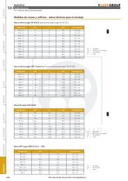
Gewinde- und Bohrungsmaße – <strong>Technische</strong> <strong>Daten</strong> <strong>für</strong> <strong>den</strong> <strong>Einbau</strong><br />
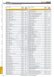
Anhang<br />
<strong>Technische</strong> Tabellen<br />
T21: Gewindemaße <strong>für</strong> Kabelverschraubungen<br />
T21<br />
ÖLFLEX ®<br />
Metrisches Gewinde nach EN 60423 (<strong>für</strong> Verschraubungen nach EN 50 262)<br />
Nenngröße ø D1 P ø D2 Bohrung ø D3<br />
M12 x 1,5 12 1,5 10,6 12,3 – 0,2<br />
M16 x 1,5 16 1,5 14,6 16,3 – 0,2<br />
M20 x 1,5 20 1,5 18,6 20,3 – 0,2<br />
M25 x 1,5 25 1,5 23,6 25,3 – 0,2<br />
M32 x 1,5 32 1,5 30,6 32,3 – 0,2<br />
M40 x 1,5 40 1,5 38,6 40,4 – 0,3<br />
M50 x 1,5 50 1,5 48,6 50,4 – 0,3<br />
M63 x 1,5 63 1,5 61,6 63,4 – 0,3<br />
M75 x 1,5 75 1,5 73,6 75,4 – 0,3<br />
M90 x 2 90 2 88,8 90,4 – 0,3<br />
M110 x 2 110 2 108,8 110,4 – 0,3<br />
Metrisches Gewinde nach DIN 13 Teil 6 und 7 (<strong>für</strong> Verschraubungen nach DIN 89 280)<br />
D1 = Außen-Ø<br />
D2 = Kern-Ø Innengewinde<br />
D3 = Bohrungs-Ø<br />
P = Steigung<br />
UNITRONIC ®<br />
ETHERLINE ®<br />
HITRONIC ®<br />
Nenngröße ø D1 P ø D2 Bohrung ø D3<br />
M18 x 1,5 18 1,5 16,4 18,3 – 0,2<br />
M24 x 1,5 24 1,5 22,4 24,3 – 0,2<br />
M30 x 2 30 2 27,8 30,3 – 0,2<br />
M36 x 2 36 2 33,8 36,3 – 0,2<br />
M45 x 2 45 2 42,8 45,4 – 0,3<br />
M56 x 2 56 2 53,8 56,4 – 0,3<br />
M72 x 2 72 2 69,8 72,5 – 0,4<br />
M80 x 2 80 2 77,8 80,5 – 0,4<br />
M105 x 2 105 2 102,8 105,5 – 0,4<br />
PG Gewinde nach DIN 40430<br />
EPIC ®<br />
SKINTOP ®<br />
Nenngröße ø D1 P ø D2 Bohrung ø D3<br />
PG 7 12,5 1,27 11,3 13,0 ± 0,2<br />
PG 9 15,2 1,41 13,9 15,7 ± 0,2<br />
PG 11 18,6 1,41 17,3 19,0 ± 0,2<br />
PG 13,5 20,4 1,41 19,1 21,0 ± 0,2<br />
PG 16 22,5 1,41 21,2 23,0 ± 0,2<br />
PG 21 28,3 1,588 26,8 28,8 ± 0,2<br />
PG 29 37,0 1,588 35,5 37,5 ± 0,3<br />
PG 36 47,0 1,588 45,5 47,5 ± 0,3<br />
PG 42 54,0 1,588 52,5 54,5 ± 0,3<br />
PG 48 59,3 1,588 57,8 59,8 ± 0,3<br />
D1 = Außen-Ø<br />
D2 = Kern-Ø Innengewinde<br />
D3 = Bohrungs-Ø<br />
P = Steigung<br />
SILVYN ®<br />
FLEXIMARK ®<br />
NPT Gewinde nach ANSI B1.20.2 – 1983<br />
Nenngröße ø D1 P Bohrung ø D3<br />
NPT 1/4" 13,7 1,41 14,1 – 0,2<br />
NPT 3/8" 17,1 1,41 17,4 – 0,2<br />
NPT 1/2" 21,3 1,81 21,6 – 0,2<br />
NPT 3/4" 26,7 1,81 27,0 – 0,2<br />
NPT 1" 33,4 2,21 33,7 – 0,2<br />
NPT 1 1/4" 42,2 2,21 42,5 – 0,2<br />
NPT 1 1/2" 48,3 2,21 48,7 – 0,2<br />
NPT 2" 60,3 2,21 60,7 – 0,2<br />
D1 = Außen-Ø<br />
D3 = Bohrungs-Ø<br />
P = Steigung<br />
KABELZUBEHÖR<br />
ANHANG<br />
Aktuelle Informationen siehe www.lappkabel.de/produkte · Tel. 0 18 05/10 12 12-93 00<br />
1045
HITRONIC ® ETHERLINE ® UNITRONIC ® ÖLFLEX ®<br />
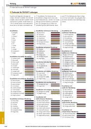
Anhang<br />
T21 <strong>Technische</strong> Tabellen<br />
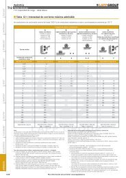
T21: Anzugsdrehmomente und <strong>Einbau</strong>maße <strong>für</strong> Kabelverschraubungen<br />
■ Anzugsdrehmomente* <strong>für</strong> SKINTOP ® Verschraubungen metrisch<br />
Tabelle der empfohlenen Anzugsdrehmomente (Hutmutter, Anschlussgewinde) <strong>für</strong> SKINTOP ® metrische Ausführung zur Erreichung der<br />
Schutzart und Zugentlastung der Kategorie A nach EN 50262. Nähere Informationen zur Schutzart siehe Produktseite.<br />
Nenngröße<br />
Kunststoff<br />
Anzugsdrehmomente in Nm<br />
M12 x 1,5 1,5 8<br />
M16 x 1,5 3,0 10<br />
M20 x 1,5 6,0 12<br />
M25 x 1,5 8,0 12<br />
M32 x 1,5 10,0 18<br />
M40 x 1,5 13,0 18<br />
M50 x 1,5 15,0 20<br />
M63 x 1,5 16,0 20<br />
M63 x 1,5 plus - 25<br />
M75 x 1,5 - 30<br />
M90 x 2 - 45<br />
M110 x 2 - 55<br />
* Hinweis: Für ATEX-Verschraubungen sind die jeweiligen Anzugsdrehmomente aus <strong>den</strong> entsprechen<strong>den</strong> Bedienungsanleitungen zu entnehmen.<br />
(Bedienungsanleitungen sind im Lieferbeutel enthalten).<br />
Metall<br />
■ Vorgeschriebene Anzugsdrehmomente* nach DIN/VDE 0619,<br />
Punkt 7 <strong>für</strong> SKINTOP ® Verschraubungen PG<br />
ANHANG KABELZUBEHÖR FLEXIMARK ® SILVYN ® SKINTOP ® EPIC ®<br />
Nenngröße<br />
Drehmomente <strong>für</strong> Zwischenstutzen in Nm<br />
Drehmomente <strong>für</strong> Hutmutter in Nm<br />
Kunststoff Metall Kunststoff<br />
PG 7 2,5 6,25 1,7<br />
PG 9 3,75 6,25 2,5<br />
PG 11 3,75 6,25 2,5<br />
PG 13,5 3,75 6,25 2,5<br />
PG 16 5,0 7,5 3,3<br />
PG 21 7,5 10,0 5,0<br />
PG 21 7,5 10,0 5,0<br />
PG 29 7,5 10,0 5,0<br />
PG 36 7,5 10,0 5,0<br />
PG 42 7,5 10,0 5,0<br />
PG 48 7,5 10,0 5,0<br />
Obige Tabellenwerte gelten als Anzugsdrehmomente <strong>für</strong> die Zwischenstutzen und als maximale Anzugsdrehmomente <strong>für</strong> die Hutmuttern unter Normklima.<br />
Beachten Sie, dass bei verschie<strong>den</strong>en Kabelmantelmaterialien geringere Drehmomente anzuwen<strong>den</strong> sind, da es sonst zu einer Schädigung des Kabelmantels<br />
kommen kann.<br />
■ <strong>Einbau</strong>maße und Schlüsselweiten <strong>für</strong> Kabelverschraubungen<br />
Der Durchmesser A gibt <strong>den</strong> erforderlichen Montageraum zum zugehörigen Sechskant an. Dieser Durchmesser entspricht dem Eckmaß<br />
des Sechskantes zuzüglich eines Montagezuschlages.<br />
SW ø A SW ø A SW ø A<br />
9 10,4 27 30,6 47 52,5<br />
11 12,5 28 31,8 50 58,3<br />
13 14,9 29 32,5 53 60,0<br />
14 16,0 30 34,0 54 61,0<br />
15 17,1 32 36,2 55 62,0<br />
16 18,2 33 37,2 57 64,4<br />
17 19,4 36 40,5 60 67,5<br />
18 20,4 37 41,5 64 72,3<br />
19 22,0 39 44,0 65 73,1<br />
20 22,7 40 45,2 66 74,5<br />
21 23,9 41 46,1 67 74,5<br />
22 25,0 42 47,0 95 105<br />
24 27,3 45 51,2 115 127<br />
25 28,3 45 51,2 135 150<br />
26 29,5 46 52,5<br />
1046<br />
Aktuelle Informationen siehe www.lappkabel.de/produkte · Tel. 0 18 05/10 12 12-93 00