e a s y l i f t s y s t e m - Bansbach
e a s y l i f t s y s t e m - Bansbach
e a s y l i f t s y s t e m - Bansbach

Sie wollen auch ein ePaper? Erhöhen Sie die Reichweite Ihrer Titel.
YUMPU macht aus Druck-PDFs automatisch weboptimierte ePaper, die Google liebt.
e a s y l i f t s y s t e m<br />
Ihre Ansprechpartner in Deutschland:<br />
PLZ-Bereich<br />
01000 – 17999 Kegel Industrievertretung<br />
39000 – 39999 Ginsterweg 6<br />
98000 – 99999 D-02699 Königswartha<br />
Tel. 035931/235-0 Fax 035931/235-19<br />
eMail kegel-product@t-online.de<br />
18000 – 32999 Pro-Tool GmbH<br />
38000 – 38999 Beckersbergstraße 16<br />
49000 – 49999 D-24558 Henstedt-Ulzburg<br />
Tel. 04193/1418 Fax 04193/1419<br />
eMail info@protopro.de<br />
33000 – 37999 Jaweg-Products<br />
40000 – 48999 Eggershover Gasse 20<br />
50000 – 63999 D-41569 Rommerskirchen<br />
Tel. 02183/450045 Fax 02183/81355<br />
eMail jakubczak@t-online.de<br />
64000 – 79999 Schönthaler & Weinhold GmbH<br />
88000 – 89199 Bühlstraße 20<br />
89500 – 89999 D-73630 Remshalden-Grunbach<br />
97000 – 97999 Tel. 07151/61704 Fax 07151/609362<br />
eMail info@schoenthaler-weinhold.com<br />
80000 – 87999 Pracher Industrieservice<br />
89200 – 89499 Lindenring 51<br />
90000 – 96999 D-82024 Taufkirchen<br />
Tel. 089/6148851 Fax 089/6148753<br />
eMail pracher@pracher.de<br />
<strong>Bansbach</strong> easylift GmbH<br />
Barbarossastraße 8<br />
D-73547 Lorch<br />
Tel. +49 (0) 7172/9107-0<br />
Fax +49 (0) 7172/9107-44<br />
info@bansbach.de<br />
www.bansbach.de<br />
Technische Änderungen und Druckfehler vorbehalten! • The catalogue is subject to technical alterations and printing mistakes!<br />
DE / 04 / 2005
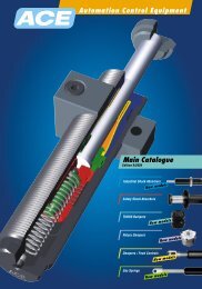
Übersicht<br />
Overview<br />
i<br />
Inhalt Index<br />
4 6<br />
8<br />
12<br />
28<br />
32<br />
36<br />
40<br />
48<br />
Das Unternehmen<br />
The Company<br />
Zertifizierte<br />
Qualität<br />
Certified<br />
Quality<br />
Gasdruckfedern<br />
Gas Springs<br />
Blockierbare<br />
Gasdruckfedern<br />
Lockable<br />
Gas Springs<br />
Gaszugfedern<br />
(& Blockierbare)<br />
Gas Traction<br />
Springs<br />
(& Lockable)<br />
Edelstahl<br />
Gasfedern<br />
Stainless Steel<br />
Gas Springs<br />
Dämpfer<br />
Damper<br />
Anschlußteile<br />
und Zubehör<br />
Connecting Parts<br />
Technische<br />
Informationen<br />
Technical<br />
Information<br />
<strong>Bansbach</strong>, das international<br />
agierende Unternehmen<br />
mit über 40<br />
Jahren Erfahrung bei der<br />
Herstellung von Qualitäts-<br />
Gasfedern, entwickelte<br />
das innovative easylift<br />
System.<br />
<strong>Bansbach</strong> easylift is an<br />
international operating<br />
company with over 40<br />
years experience in the<br />
manufacturing of high<br />
quality gas springs which<br />
developed the easylift<br />
system.<br />
Zertifizierte Qualität zur<br />
Erfüllung höchster<br />
Ansprüche, zum Beispiel<br />
für den Bereich Luftfahrt,<br />
bilden die Grundlagen für<br />
den internationalen Erfolg<br />
des easylift ® Systems.<br />
<strong>Bansbach</strong> maintains many<br />
international quality certifications<br />
in many different<br />
markets, to include aeronautics<br />
for example. The<br />
success of the easylift ®<br />
system is based on these<br />
certifications. Quality is<br />
assured, wherever you are<br />
in the world.<br />
Das easylift ® System ermöglicht<br />
die Zusammenstellung<br />
einer Gasfeder ähnlich dem<br />
bekannten “Lego-Baukastenprinzip”.<br />
Vorteil: unzählige<br />
Varianten aus bestehenden<br />
Komponenten, individuell nach<br />
Kundenwunsch und innerhalb<br />
kürzester Fertigungszeiten!<br />
The easylift ® system is based<br />
on the “Lego-modular<br />
system”. Advantage: There<br />
are an infinite number of off<br />
the shelf component combinations.<br />
This allows you to pick<br />
and choose from the most<br />
comprehensive product line<br />
available. You will have a<br />
“plug and play” solution with<br />
the shortest lead-time in the<br />
industry.<br />
Das weltweit umfangreichste<br />
Programm an<br />
blockierbaren Funktionsvarianten<br />
– bis hin zu beidseitig<br />
absolut starr<br />
blockierbaren easylift<br />
Gasfedern.<br />
The most comprehensive<br />
programme of locking<br />
variations worldwide – up<br />
to absolutely rigid locking<br />
easylift gas springs in both<br />
directions.<br />
„Zugkräftige“ Argumente<br />
bieten diese Produktvarianten<br />
nicht nur für ideenreiche<br />
Konstrukteure...<br />
eine Fülle von Möglichkeiten<br />
ohne Bedarf an<br />
Fremdenergie!<br />
These product variants<br />
offer "attractive" arguments,<br />
not only for creative<br />
design engineers<br />
...plenty of possibilities<br />
without extra energy!<br />
Alle Ausführungen der<br />
easylift-Gasfedern sind<br />
auch aus hochwertigem<br />
rostfreien Material verfügbar<br />
(316L).<br />
Every type of gas spring is<br />
also available in rust<br />
resistant stainless steel<br />
(316L).<br />
...werden eingesetzt als<br />
Sicherheits- und Funktionselemente<br />
zum<br />
Dämpfen von Geschwindigkeiten<br />
und Bremsen<br />
von Massen.<br />
...are used as safety- and<br />
function elements in order<br />
to damp speed and to<br />
slow down masses.<br />
Die richtige „Verbindung“<br />
haben Sie bei <strong>Bansbach</strong><br />
auf jeden Fall...<br />
...und dies beweisen wir<br />
auch durch die Vielfalt der<br />
easylift-Anschlußteile.<br />
With <strong>Bansbach</strong>, you will<br />
surely have the right "connection"...<br />
...and we will prove that<br />
with the big variety of the<br />
easylift connecting parts.<br />
Wichtige technische<br />
Hinweise zur fachgerechten<br />
Anwendung<br />
von easylift Gasfedern<br />
Important technical information,<br />
for the professional<br />
use of Easylift gas<br />
springs.<br />
2 <strong>Bansbach</strong> easylift<br />
<strong>Bansbach</strong> easylift<br />
3
Über uns | About us<br />
<strong>Bansbach</strong> - das Unternehmen<br />
<strong>Bansbach</strong> - the company<br />
Tradition & Wachstum<br />
Das Unternehmen <strong>Bansbach</strong> wurde im<br />
Jahre 1919 gegründet. Zunächst im Bereich<br />
Werkzeugbau tätig, mit eigener Drehteilfertigung,<br />
entwickelte sich das Unternehmen<br />
mit über 40-jähriger Erfahrung in<br />
der Fertigung von Gasfedern zum weltweit<br />
agierenden Premium-Anbieter.<br />
Die Niederlassung in Singapur bildet seit<br />
1994 das Zentrum der Asienaktivitäten als<br />
wichtiger Bestandteil des weltweiten<br />
<strong>Bansbach</strong>-Vertriebsnetztes.<br />
Moderne Produktion<br />
Moderne Produktionsprozesse und<br />
zertifizierte Qualitätssicherung<br />
gewährleisten die Einhaltung höchster<br />
Qualitätsanforderungen bei <strong>Bansbach</strong><br />
easylift. Im eigenen Test- und<br />
Entwicklungslabor werden Produkte<br />
und Technologien permanent weiterentwickelt.<br />
Ein eigener, kompletter<br />
Maschinenpark ermöglicht eine hohe<br />
Fertigungstiefe bei kürzesten<br />
Fertigungszeiten.<br />
Aus Größe resultiert Verantwortung<br />
Bis zum heutigen Tag wächst das<br />
Unternehmen beständig mit den<br />
Wünschen und Anforderungen der Kunden<br />
- damit wächst auch die Verantwortung für<br />
die Gewährleistung umweltschonender<br />
Fertigungsprozesse und der ausschließliche<br />
Einsatz von Materialien, die keine kritischen<br />
Stoffe beinhalten.<br />
Als namhaftes Unternehmen am Standort<br />
Lorch bietet <strong>Bansbach</strong> easylift seinen<br />
Mitarbeitern einen sicheren Arbeitsplatz.<br />
Tradition and growth<br />
<strong>Bansbach</strong> was found 1919 as a manufacturer<br />
of stamping tools. With our in house turning<br />
shop, and over 40 years of experience<br />
in gas spring production, we evolved into a<br />
world wide operating premium supplier.<br />
The Singapore branch has been the center<br />
of activities in the Asia since 1994 which is<br />
now an essential part of the world wide<br />
<strong>Bansbach</strong> distribution network.<br />
Modern production<br />
Modern production processes and a<br />
certified quality system, guarrantee<br />
that <strong>Bansbach</strong> gas springs are of the<br />
highest qualitiy standard. Using our<br />
test and development laboratory, products<br />
and technology are constantly<br />
being improved. A complete machine<br />
shop allows for a deep vertical range<br />
of manufacture with shortest lead<br />
times.<br />
Size results in Responsibility<br />
Along with our constant growth, our<br />
responsibility, to guarantee an environmentally<br />
friendly process is not neglected.<br />
We have been very successful in limiting<br />
our production materials to environmentally<br />
friendly materials and are<br />
recognized in the town of Lorch as a safe<br />
workplace.<br />
4 <strong>Bansbach</strong> easylift<br />
<strong>Bansbach</strong> easylift<br />
5
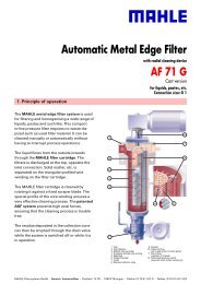
hochwertiges Endstück<br />
high-quality connecting part<br />
Gas<br />
gas<br />
Zylinderrohr<br />
pulverbeschichtet<br />
Cylinder,<br />
powder-coated<br />
Fettkammer<br />
grease chamber<br />
Dichtung<br />
sealing<br />
Dichtungsring<br />
sealing ring<br />
CeramPro ®<br />
technology<br />
Ceram Pro ® Kolbenstange<br />
Ceram Pro ® piston rod<br />
Qualität | Quality<br />
Kolben<br />
piston<br />
Dichtungsring<br />
sealing ring<br />
Gleitlager<br />
bushing<br />
hochwertiges Anschlussteil<br />
Kolbenstange<br />
high-quality connecting part<br />
piston rod<br />
CeramPro ®<br />
technology<br />
Endstück in unterschiedlichen<br />
Ausführungen möglich<br />
Connecting parts available in many<br />
variations<br />
Zylinder aus Metall, pulverbeschichtet<br />
(verfügbar in schwarz, weiß und silber)<br />
Cylinder out of steel and powder-coated<br />
(available in black, white and silver)<br />
Kolben zur<br />
Geschwindigkeitssteuerung<br />
Piston for<br />
speed control<br />
Hochwertiges, einzigartiges Führungslager<br />
mit integrierter Fettkammer<br />
A high-quality and unique guiding piece<br />
with integrated grease chamber<br />
Ceram Pro ® Kolbenstange<br />
äußerst korrosionsbeständig<br />
Ceram Pro ® piston rod, extremely<br />
rust and corrosion resistant<br />
Anschlußteil in verschiedenen<br />
Ausführungen möglich<br />
Connecting part available in many<br />
variations<br />
6 <strong>Bansbach</strong> easylift<br />
easylift Gasfedern für sicheres,<br />
gezieltes Bewegen und Positionieren<br />
easylift gas springs for save<br />
and efficient moving and adjusting<br />
Zertifizierte Qualität<br />
<strong>Bansbach</strong> Gasfedern werden ausschließlich<br />
aus qualitativ hochwertigen,<br />
umweltverträglichen Materialien<br />
gefertigt. Durch kontinuierliche Überwachung<br />
von Rohmaterialien, Durchführung<br />
von Testprogrammen und<br />
Qualitätsüberwachung während des<br />
Fertigungsprozesses, kann eine konstant<br />
hohe Qualität gewährleistet werden.<br />
Bei Nachbestellungen können die<br />
Produkte durch moderne Fertigungsverfahren<br />
exakt reproduziert werden.<br />
Certified Quality<br />
<strong>Bansbach</strong> Gas springs are manufactured<br />
out of the highest quality, environmentally<br />
friendly materials. Consistent<br />
quality is guaranteed because of diligent<br />
monitoring of raw materials, an<br />
aggressive testing program and a redundant<br />
quality control program throughout<br />
the production process. Re-ordered<br />
products are consistently produced<br />
accurately by using our technologically<br />
advanced manufacturing processes.<br />
Vorteile von <strong>Bansbach</strong> Gasfedern:<br />
höchste Korrosionsbeständigkeit durch<br />
Pulverbeschichtung des Zylinders und<br />
CeramPro ® -Oberfläche der Kolbenstange<br />
Minimale Reibungswerte, zur Fertigung<br />
von niedrigsten Ausschubkräften<br />
Beste Standzeiten/Langlebigkeit<br />
Schutz bei Vibration und leichten<br />
Seitenkräften<br />
Integrierte Fettkammer<br />
Niedrige Losbrechkraft<br />
Lageunabhängiger Einbau und Lagerung<br />
Advantages of <strong>Bansbach</strong> Gas springs:<br />
Highest corrosion resistance achieved<br />
through powder coated cylinders and<br />
CeramPro ® treated piston rod surfaces.<br />
Minimal friction for the production of<br />
lowest extension forces.<br />
Best life cycles.<br />
Protection against vibration and<br />
light side forces.<br />
Integrated grease chamber.<br />
Low break away forces.<br />
Installation and storage in any position.<br />
CeramPro ® Kolbenstange<br />
Die CeramPro ® Oberfläche - eine innovative<br />
Neuentwicklung aus dem <strong>Bansbach</strong><br />
Entwicklungslabor - bietet maximale<br />
Korrosionsbeständigkeit für die Kolbenstange.<br />
Durch eine spezielle Oberflächenbehandlung<br />
erhält diese eine extrem<br />
glatte, beständige Oberfläche mit sehr<br />
guten Laufeigenschaften und dadurch<br />
bestmöglichen Schutz vor Verschleiß.<br />
CeramPro ® Piston rod<br />
The CeramPro ® surface treatment is a<br />
new innovative development out of the<br />
<strong>Bansbach</strong> development laboratory.<br />
CeramPro ® offers maximum rust and<br />
corrosion resistance of the piston rod.<br />
This special surface treatment provides<br />
an extremely smooth surface with excellent<br />
operating characteristics that provide<br />
superior protection against abrasion<br />
to the rod.<br />
<strong>Bansbach</strong> easylift<br />
7
Medizin und Rehatechnik<br />
Funktionsmöbel<br />
Maschinenbau<br />
Luftfahrtindustrie<br />
Fahrzeugindustrie<br />
Freizeit und Fitness<br />
Haustechnik<br />
Sonstiges<br />
Gasdruckfedern<br />
Medical & rehabilitation equipment<br />
Furniture<br />
Gas springs<br />
Machinery<br />
Aerospace Industry<br />
Vehicle Industry<br />
Leisure and Training Equipment<br />
House technique<br />
Others<br />
Luftfahrtindustrie<br />
Aerospace Industry<br />
Fahrzeugindustrie<br />
Vehicle Industry<br />
Möbelindustrie<br />
Furniture<br />
Maschinenbau<br />
Machinery<br />
Sonstiges<br />
Others<br />
Gesteuert drücken,<br />
heben oder senken<br />
ohne Fremdenergie!<br />
Controlled pushing,<br />
lifting or lowering<br />
without external energy.<br />
Wir fertigen jede Größe und jede Ausschubkraft<br />
nach Ihren Wünschen und exakt für<br />
Ihren Bedarfsfall. Vom Fahrzeugbau und der<br />
Möbelfabrikation über unzählige<br />
Anwendungen im Maschinen- und Apparatebau,<br />
Speziallösungen für Medizintechnik bis<br />
hin zum Flugzeugbau – überall finden easylift<br />
Gasdruckfedern sinnvollen Einsatz. Durch<br />
ständige Fertigung von Zwischengrößen und<br />
durch umfangreiche Lagerhaltung von Bauteilen<br />
können fast alle Wünsche kurzfristig<br />
erfüllt werden.<br />
Our production range covers nearly all dimensions<br />
and forces which are required for your<br />
specific application. Easylift gas springs are<br />
used anywhere in the industrial field.<br />
Besides the automobile and furniture industry,<br />
there are innumberable applications in the<br />
machinery and equipment design. We can also<br />
offer special solutions to meet the requirements<br />
in the medical and aircraft industry.<br />
The continuous production of special sizes<br />
and our extensive stock enable us to meet<br />
nearly all requirements within a remarkable<br />
short time.<br />
Sie stehen als Konstrukteur vor einem<br />
bestimmten Problem, das mit kontrollierter<br />
Bewegung zu tun hat und idealerweise<br />
ohne Fremdenergie gelöst<br />
werden soll? Dann sind Sie Ihrer<br />
Lösung mit dieser Broschüre einen<br />
großen Schritt näher.<br />
Wir unterstützen namhafte Hersteller<br />
bei der Entwicklung neuer Produkte –<br />
sprechen auch Sie mit uns!<br />
You, as an engineer, have a certain<br />
problem which has to do with controlled<br />
movement and which should be<br />
solved without extra engergy? Then,<br />
this brochure will be a big step to the<br />
solution of your problem. We support<br />
well-known companies in developing<br />
new products – please contact us!<br />
Die meisten Fragen werden Ihnen<br />
unsere erfahrenen Produkt- und Konstruktionsberater<br />
bereits am Telefon<br />
beantworten. Natürlich bieten Ihnen<br />
auch unsere Internet-Seiten weitere<br />
qualifizierte Informations-, Planungsund<br />
Bestellmöglichkeiten.<br />
<strong>Bansbach</strong> easylift im Internet unter:<br />
www.bansbach.de<br />
Testen Sie unser<br />
Online-Berechnungsprogramm!<br />
Our product engineers will answer<br />
most of your questions on the phone.<br />
Our homepage offers further details<br />
with planning and order information.<br />
You will find us under:<br />
www.bansbach.de<br />
Please test our<br />
Online-Calculation-Software!<br />
8 <strong>Bansbach</strong> easylift<br />
<strong>Bansbach</strong> easylift<br />
9
Gasdruckfedern | Gas springs<br />
Gasdruckfedern | Gas springs<br />
EL1<br />
EL2<br />
A<br />
øy<br />
ø x<br />
F<br />
Ausschubkraft extension force<br />
Anschlußteil Zylinder<br />
connecting part cylinder<br />
Bauart<br />
model<br />
Ausschubgeschwindigkeit/Dämpfung push-out speed/damping<br />
Anschlußteil Kolbenstange<br />
connecting part piston rod<br />
Gasdruckfedern | Gas springs<br />
Bestell-Beispiel | Order-Example<br />
A1 A1 – 4<br />
Anschlußteile<br />
Kolbenstange<br />
connecting parts<br />
piston rod<br />
siehe<br />
Seite 42<br />
Anschlußteile<br />
see page 42<br />
connecting parts<br />
Anschlußteile<br />
Zylinder<br />
connecting parts<br />
cylinder<br />
siehe<br />
Seite 42<br />
Anschlußteile<br />
see page 42<br />
connecting parts<br />
Bauart<br />
model<br />
– Normalausführung standard<br />
A nach Kundenzeichnung accord. to your drawing<br />
B nach eigener Zeichnung according to our drawing<br />
C mit Abstreifer with scraper<br />
D mit Überrohr with covertube<br />
E mit neutralen Etiketten with neutral labels<br />
F mit Ventil im Zylinder-Endstück<br />
with valve inside the cylinder<br />
H mit Spezialdichtungen für Temperaturen bis 200˚ C<br />
with special seals for temperatures up to 200˚ C<br />
N nichtrostende Ausführung aus Material 1.4404<br />
stainless steel version in 1.4404<br />
R mit erhöhter Reibung with increased friction<br />
S mit arretierbarem Schutzrohr (ab 150 mm Hub)<br />
with lockable cover tube (above 150 mm stroke)<br />
Ausschubgeschwindigkeit/Dämpfung<br />
push-out speed/damping<br />
0 schnell, keine Enddämpfung fast, no end damping<br />
1 schnell, normale Enddämpfung fast, normal end damping<br />
2 schnell, starke Enddämpfung fast, increased end damping<br />
3 normal, keine Enddämpfung normal, no end damping<br />
4 normal, normale Enddämpfung normal, normal end damping<br />
5 normal, starke Enddämpfung normal, increased end damping<br />
6 langsam, keine Enddämpfung slow, no end damping<br />
7 langsam, normale Enddämpfung slow, normal end damping<br />
8 langsam, starke Enddämpfung slow, increased end damping<br />
9 Sonstige Varianten other variations<br />
Enddämpfung nur wirksam mit nach unten weisender Kolbenstange<br />
To recognize end damping please install with piston rod downwards.<br />
0 200 482 001* 500N<br />
Durchmesser Kolbenstange/ Zylinder<br />
diameter piston rod/cylinder<br />
Hub<br />
stroke<br />
Einbaulänge**<br />
extended length**<br />
Index Nummer<br />
index number<br />
Ausschubkraft<br />
extension-force<br />
Øx/Øy (mm) A (mm) mind. min. EL2 (mm) F1 (N) Progression progression<br />
G = 4/12 10-150 2x Hub stroke +30<br />
*Durch die Indexnummer – nur für<br />
Ihre Nachbestellung erforderlich –<br />
7-200 ca. 21 %<br />
6 = 6/15 10-150 2x Hub stroke +30 können wir einmal gefertigte<br />
10-400 ca. 27 %<br />
C = 6/19 10-150 2x Hub stroke +42<br />
Produkte exakt reproduzieren. Sie<br />
erhalten den Indexcode mit der<br />
10-400 ca. 16 %<br />
D = 6/22 10-150 2x Hub stroke +43<br />
Auftragsbestätigung / Rechnung.<br />
10-400 ca. 11 %<br />
0 = 8/19 10-300 2x Hub stroke +46<br />
*With the index no. – only necessary<br />
for repeating orders – we can reproduce<br />
30-700 ca. 33 %<br />
1 = 8/22 10-300 2x Hub stroke +46<br />
exactly the same gas spring<br />
which has already been produced.<br />
30-700 ca. 22 %<br />
E = 8/28 10-300 2x Hub stroke +60<br />
You will receive the index no. with<br />
the order confirmation / invoice.<br />
30-700 ca. 13 %<br />
2 = 10/22 20-800 2x Hub stroke +47 50-1300 ca. 39 %<br />
3 = 10/28 20-800 2x Hub stroke +60 50-1300 ca. 21 %<br />
4 = 12/28 20-1000 2x Hub stroke +60 100-1700 ca. 33 %<br />
5 = 14/28 20-1000 2x Hub stroke +60 150-2600 ca. 52 %<br />
A = 10/40 20-1000 2x Hub stroke +70 50-1300 ca. 8 %<br />
F = 12/40 20-1000 2x Hub stroke +70 100-1700 ca. 13 %<br />
B = 14/40 20-1000 2x Hub stroke +70 150-2600 ca. 18 %<br />
7 = 20/40 20-1000 2x Hub stroke +90 200-5000 ca. 45 %<br />
Optionen | Options<br />
Bestellbeispiel | Order Example<br />
A1 A1 – 4 0 200 482 001* 500N<br />
Durchmesser<br />
size<br />
Øx/Øy (mm)<br />
Abstreifer<br />
scraper<br />
EL 2 +10 mm<br />
Überrohr<br />
cover tube<br />
EL 2 +10 mm<br />
Ventil<br />
valve<br />
4/12<br />
6/15 +5mm<br />
6/19<br />
6/22 Kunststoff plastic<br />
8/19 Stahl steel<br />
8/22 Kunststoff plastic<br />
8/28 Kunststoff plastic<br />
10/22 Kunststoff plastic<br />
10/28 Kunststoff plastic<br />
12/28 Kunststoff plastic<br />
14/28 Kunststoff plastic<br />
10/40 Stahl steel<br />
12/40 Stahl steel<br />
14/40 Stahl steel<br />
20/40<br />
Hochtemperatur<br />
Dichtung<br />
high-temp. seals<br />
Kältebest.<br />
Dichtung<br />
low-temp. seals<br />
Nirosta (siehe Seite 32)<br />
stainless steel<br />
(see page 32)<br />
Reibung<br />
friction<br />
EL 2 +10 mm<br />
Arretierbares Schutzrohr<br />
lockable cover tube<br />
EL 2 +10 mm<br />
EL<br />
EL2<br />
**Achtung | **Attention Festlegung einer Ausführung - Beispiel Determination of a gas spring type - Example<br />
Berechnung der Einbaulänge<br />
erfolgt mit ausgefahrener<br />
Kolbenstange. Die Länge der<br />
gewünschten Anschlußteile zur<br />
Ermittlung der Gesamteinbaulänge<br />
hinzurechnen.<br />
The total length is calculated<br />
when the piston rod is extended.<br />
Please add the length of the connecting<br />
parts in order to find out<br />
the total length.<br />
Einbaulänge EL2 = ohne<br />
Gelenkaugen/ohne Gewindelänge<br />
gemessen<br />
length EL2 = measured without<br />
hinge eyes and threads<br />
Wie empfehlen die Festlegung der Baureihe anhand der notwendigen<br />
Kraft und der vorgesehenen Hub-/ Einbaulänge. Im<br />
Bestellbeispiel wurde aufgrund von 500N und 200 mm Hub die<br />
Baureihe 8/19 mm festgelegt. Die mögliche Einbaulänge<br />
berechnet sich wie folgt:<br />
2 x 200 mm (Hub) + 46 mm = 446 mm (EL2)<br />
+ Anschlussteil Kolbenstange A1 = 20 mm (Seite 42)<br />
+ Anschlussteil Zylinder A1 = 16 mm (Seite 42)<br />
Mindest-Einbaulänge = 482 mm (EL)<br />
Aufrundungen auf übliche Längen, z.B. 485 / 490 / 500 oder auf<br />
vorhandene Befestigungspunkte, z.B. 550 sind jeweils aus<br />
lagerhaltigen Bauteilen kurzfristig lieferbar.<br />
We recommend the determination of a gas spring type by<br />
the required force and the intended stroke-/ extended<br />
length. In the order example the 8/19 type was determined<br />
due to 500N and 200 mm stroke. The possible extended<br />
length is calculated as follows:<br />
2 x 200 mm (stroke) + 46 mm = 446 mm (EL2)<br />
+ connecting part piston rod A1 = 20 mm (page 42)<br />
+ connecting part cylinder A1 = 16 mm (page 42)<br />
Minimum extended length = 482 mm (EL)<br />
Rounding up on common lengths, e.g. 485 / 490 / 500 or on<br />
existing mounting points, e.g. 550 are each available in a<br />
short time due to stocking components.<br />
10 <strong>Bansbach</strong> easylift<br />
Technische Änderungen vorbehalten • We reserve the right to make technical changes at any time without prior notice<br />
<strong>Bansbach</strong> easylift<br />
11
Blockierbare Gasdruckfedern<br />
Lockable Gas Springs<br />
Medizin- und Rehatechnik<br />
Medical & rehabilitation equipment<br />
Fitness und Freizeit<br />
Leisure and Training equipment<br />
Funktionsmöbel<br />
Furniture<br />
Rehatechnik<br />
Rehabilitation equipment<br />
Medizintechnik<br />
Medical equipment<br />
Fahrzeug-/Luftfahrtindustrie<br />
Vehicle/Aerospace Industry<br />
Gesteuert drücken, heben und<br />
positionieren bis hin<br />
zur beidseitig absolut<br />
starren Blockierbarkeit!<br />
Controlled pushing, lifting and<br />
adjusting up to<br />
absolutely rigid locking in<br />
both directions.<br />
Immer dann, wenn auf bewegliche Konstruktionsteile<br />
erhebliche Kräfte einwirken, erhält die zuverlässige<br />
Blockierbarkeit eine hohe Bedeutung.<br />
Durch Betätigung des Auslösestiftes kann die easylift<br />
Gasfeder in jeder gewünschten Position des gesamten<br />
Hubes sicher arretiert werden. Je nach den in Ihrer<br />
Anwendung auftretenden Kräften, können wir Ihre<br />
blockierbaren easylift Gasfedern für unterschiedliche<br />
Belastungsgrenzen sinnvoll dimensionieren. In dieser<br />
Produktreihe ist die beidseitig absolut starr blockierbare<br />
easylift Gasfeder eine weltweit beachtete<br />
Innovation.<br />
When considerable forces influence moveable construction<br />
parts, the reliable locking is important.<br />
The piston rod of the lockable easylift gas spring can<br />
be adjusted in every required position of the whole<br />
stroke by actuating the release pin. Depending on the<br />
occuring forces in your application, we can fit your<br />
lockable easylift gas spring for different load limits in a<br />
reasonable way. In this production programme, the<br />
absolutely rigid locking easylift gas spring in both<br />
directions is a recognized innovation worldwide.<br />
Auch bei den blockierbaren Gasfedern des<br />
easylift Systems liegt Ihr Kernnutzen in der<br />
Unabhängigkeit von einer externen Energiequelle,<br />
den sehr kompakten Ausmaßen und<br />
der gedämpften, kontrollierten Bewegung.<br />
Die 4 Grundbauarten und weitere<br />
Funktionsvarianten entnehmen Sie den<br />
Seiten 14-19. Oder wenn für Sie möglich -<br />
anhand der vielen Funktionsmodelle, die wir<br />
Ihnen bei uns zeigen können.<br />
Wir unterstützen Sie bei der Realisierung<br />
Ihrer Projekte.<br />
The main use of the lockable gas springs of<br />
the easylift system is the independence of<br />
an external energy source, the comprehensive<br />
measures and the damped, controlled<br />
movement.<br />
Please see the 4 basic models and further<br />
function variations on pages 14-19. Or if you<br />
have the possibility you can see numerous<br />
function models in our facility. We assist you<br />
in the realisation of your projects.<br />
Natürlich haben blockierbare easylift<br />
Gasfedern die gleichen positiven<br />
Eigenschaften – geringe Reibungskräfte und<br />
hohe Betriebssicherheit – wie die anderen<br />
easylift Gasfedertypen. Die blockierbaren<br />
easylift Gasfedern erhalten Sie in Ihrer<br />
gewünschten Größe und Ausschubkraft<br />
innerhalb kürzester Lieferzeiten.<br />
Of course, lockable easylift gas springs have<br />
the same positive characteristics – low friction<br />
forces and high reliability – as the other<br />
easylift gas spring types. You will receive the<br />
lockable easylift gas springs with the requested<br />
size and force within shortest time.<br />
12 <strong>Bansbach</strong> easylift<br />
<strong>Bansbach</strong> easylift<br />
13
Blockierbare Gasdruckfedern | Lockable Gas Springs<br />
Blockierbare Gasdruckfedern | Lockable Gas Springs<br />
EL1<br />
EL2<br />
A<br />
ø y<br />
ø x<br />
F<br />
Ausschubkraft extension force<br />
Anschlußteil Zylinder<br />
connecting part cylinder<br />
Bauart<br />
Model<br />
Ausschubgeschwindigkeit/Dämpfung push-out speed/damping<br />
Gewinde Kolbenstange<br />
thread piston rod<br />
Blockierbare Gasdruckfedern | Lockable Gas Springs<br />
Bestell-Beispiel | Order-Example<br />
K0 B1 K –<br />
Gewinde<br />
Kolbenstange<br />
thread piston rod<br />
K0 = MF 10x1x18<br />
O0 = MF 14x1,5x20<br />
W0 = MF 8 x1x16<br />
Anschlußteile<br />
Zylinder<br />
connecting parts<br />
cylinder<br />
siehe Seite 42<br />
”Anschlußteile”<br />
see page 42<br />
”connecting parts”<br />
Bauart<br />
model<br />
B Hauptbauart siehe Seite 16 Main type see page 16<br />
K Hauptbauart siehe Seite 17 Main type see page 17<br />
P Hauptbauart siehe Seite 18 Main type see page 18<br />
KX Hauptbauart siehe Seite 19 Main type see page 19<br />
A Sonderausführungen nach Kundenzeichnung Special design according to customer drawing<br />
G starre Blockierung, jedoch mit 60% niedrigerer Auslösekraft (min. F1 500N!)<br />
Rigid locking, but with 60% reduced release force (min. F1 500N!)<br />
J federnde Blockierung, jedoch mit 60% niedrigerer Auslösekraft (min. F1 500N!)<br />
Spring locking, but with 60% reduced release force (min. F1 500N!)<br />
M starre Blockierung in Einschubrichtung, ausschiebend nicht blockierbar<br />
Rigid locking in push-in direction not lockable in push-out direction<br />
T Spezialausführung, starre Blockierung, kurze Bauweise flache Federkennlinie, besonders<br />
geeignet für Höhenverstellungen, Einbaulänge EL 2 min. 2,13 x Hub + 83 mm (Progression ca. 35%)<br />
pecial models rigid locking, short length low pressure increase, especially for vertical adjustments,<br />
extended length EL 2 min. stroke x 2,13 + 83 mm (progressivity approx. 35%)<br />
U starre Blockierung in Ausschubrichtung, einschiebend nicht blockierbar<br />
Rigid locking in push-out direction, not lockable in push-in direction<br />
V starre Blockierung in Ausschub und Einschubrichtung, bei Überlastung Ausziehen ohne Lösen der<br />
Blockierung möglich<br />
Rigid locking in push-out and push in direction, pulling out without releasing the locking is possible<br />
in case of overload<br />
Ausfahrgeschwindigkeit<br />
push-out speed<br />
– = normal<br />
normal<br />
0 = schnell<br />
fast<br />
7 = langsam<br />
slow<br />
K = Kurzauslösung<br />
Auslöseweg < 1 mm<br />
anstatt < 3,5 mm<br />
short release<br />
Release travel < 1 mm<br />
instead of < 3,5 mm<br />
Die 4 Haupt-Bauarten B, K, P und KX | The 4 main types of construction B, K, P and KX >>><br />
3 045 217 001* 500N<br />
Durchmesser<br />
Kolbenstange/ Zylinder<br />
diameter piston rod/cylinder<br />
Hub<br />
stroke<br />
Einbaulänge** (siehe Seite 11)<br />
extended length** (see page 11)<br />
Index Nummer<br />
index number<br />
Ausschubkraft<br />
extension force<br />
Øx/Øy (mm) A (mm) mind. min. EL2 (mm) F1 (N)<br />
1 = 8/22 mm<br />
2 = 10/22 mm<br />
3 = 10/28 mm<br />
5 = 14/28 mm<br />
A =<br />
B =<br />
E =<br />
10/40 mm<br />
14/40 mm<br />
8/28 mm<br />
10 - 800<br />
siehe Seiten 16-19<br />
see pages 16-19<br />
siehe Seiten 16-19<br />
see pages 16-19<br />
*Durch die Indexnummer – nur für<br />
Ihre Nachbestellung erforderlich –<br />
können wir einmal gefertigte Produkte<br />
exakt reproduzieren. Sie erhalten den<br />
Indexcode mit der Auftragsbestätigung/Rechnung.<br />
*With the index no. – only necessary<br />
for repeating orders – we can reproduce<br />
exactly the same gas spring<br />
which has already been produced.<br />
You will receive the index no. with the<br />
order confirmation / invoice.<br />
0N - 2600N<br />
siehe Seiten 16-19<br />
see pages 16-19<br />
Auslösekräfte | release force<br />
Auslösekräfte bei Kolbenstange<br />
Release force for piston rod<br />
Standard<br />
Standard<br />
Für Kurzauslösung Easytouch<br />
For short hydraulic release system Easytouch<br />
Bauart G; F1 min. 500 N<br />
Type G; F1 minimum 500 N<br />
8mm 10mm 14mm<br />
0,25*F1 0,25*F1 0,08*F1<br />
0,25*F1<br />
0,16*F1<br />
0,1*F1<br />
EL<br />
EL2<br />
**Achtung | **Attention<br />
Berechnung der Einbaulänge erfolgt mit<br />
ausgefahrener Kolbenstange. Die Länge<br />
der gewünschten Anschlußteile zur<br />
Ermittlung der Gesamteinbaulänge hinzurechnen.<br />
The total length is calculated when the<br />
piston rod is extended. Please add the<br />
length of the connecting parts in order to<br />
find out the total length.<br />
Einbaulänge EL2 = ohne<br />
Gelenkaugen/ohne Gewindelänge gemessen<br />
length EL2 = measured without hinge<br />
eyes and threads<br />
Bestellbeispiel | Order Example<br />
Funktionsweise<br />
Blockierbare Gasfedern sind stufenlos über den<br />
kompletten Hub arretierbar. Durch Eindrücken<br />
des Auslösepins öffnet sich ein Kolbenventil.<br />
Das Gas bzw. Öl kann durch den Kolben strömen,<br />
die Kolbenstange fährt aus oder lässt sich<br />
einschieben. Durch Loslassen des Auslösestifts<br />
schließt das Ventil selbstständig und die<br />
Kolbenstange arretiert in der gewünschten<br />
Position. Im blockierten Zustand können je nach<br />
Bauart, Ausschubkraft und Bewegungsrichtung<br />
unterschiedlich hohe Blockierkräfte erzielt werden.<br />
Bei Überschreitung der Blockierkraft ist die<br />
Arretierfunktion nicht mehr gegeben.<br />
K0 B1 K - 3 045 217 001* 500N<br />
Function<br />
Lockable gas springs can be locked anywhere<br />
along the complete stroke. By pushing the<br />
release pin, the piston valve opens allowing gas<br />
or oil to flow through the piston and the piston<br />
rod extends or can be pushed in. When the<br />
release pin is no longer being pushed, the valve<br />
closes independently and the piston rod is<br />
locked in the desired position. When locked,<br />
depending on the type of construction, extension<br />
force and the direction of the movement,<br />
various locking forces can be achieved. When<br />
the locking force is exceeded, the locking<br />
function in no longer given.<br />
14 <strong>Bansbach</strong> easylift<br />
Technische Änderungen vorbehalten • We reserve the right to make technical changes at any time without prior notice<br />
<strong>Bansbach</strong> easylift<br />
15
Blockierbare Gasdruckfedern | Lockable Gas Springs<br />
Blockierbare Gasdruckfedern | Lockable Gas Springs<br />
EL1<br />
EL1<br />
EL2<br />
EL2<br />
A<br />
A<br />
ø y<br />
ø x<br />
ø y<br />
ø x<br />
Ausschubgeschwindigkeit<br />
push-out speed<br />
Ausschubgeschwindigkeit<br />
push-out speed<br />
Anschlußteil Zylinder<br />
connecting part cylinder<br />
Bauart<br />
Model<br />
Gewinde Kolbenstange<br />
thread piston rod<br />
Anschlußteil Zylinder<br />
connecting part cylinder<br />
Bauart<br />
Model<br />
Gewinde Kolbenstange<br />
thread piston rod<br />
Hauptbauart main type B<br />
federnd blockierbar | spring locking<br />
Bestell-Beispiel | Order-Example<br />
K0 B1 B – 3 200 507 001* 550N<br />
Gewinde<br />
Kolbenstange<br />
thread<br />
piston rod<br />
Anschlußteile<br />
Zylinder<br />
connecting<br />
parts<br />
cylinder<br />
Bauart<br />
model<br />
Ausfahrgeschwindigkeit<br />
push-out speed<br />
Baureihe<br />
size<br />
Hub<br />
stroke<br />
Einbaulänge**<br />
(siehe Seite 11)<br />
extended length**<br />
(see page 11)<br />
Progression<br />
progressivity<br />
Index Nr.*<br />
Index Nr.*<br />
Kraft<br />
force<br />
Øx/Øy mm mm mind. min. EL 2 (mm) ca. % N<br />
Hauptbauart main type K<br />
starre Blockierung in Auszugrichtung, einschiebend bedingt starr<br />
rigid locking in pull direction, push-in direction relatively rigid<br />
Bestell-Beispiel | Order-Example<br />
K0 B1 K – 3 200 594 001* 550N<br />
Gewinde<br />
Kolbenstange<br />
thread<br />
piston rod<br />
Anschlußteile<br />
Zylinder<br />
connecting<br />
parts<br />
cylinder<br />
Bauart<br />
model<br />
Ausfahrgeschwindigkeit<br />
push-out speed<br />
Baureihe<br />
size<br />
Hub<br />
stroke<br />
Einbaulänge**<br />
(siehe Seite 11)<br />
extended length**<br />
(see page 11)<br />
Progression<br />
progressivity<br />
Øx/Øy mm mm mind. min. EL 2 (mm) ca.<br />
%<br />
Index Nr.*<br />
Index Nr.*<br />
Kraft<br />
force<br />
(N)<br />
Auslöseweg<br />
< 1mm<br />
Blockierkraft Zug<br />
locking force<br />
in pull direction<br />
Auslöseweg<br />
> 2,5mm<br />
Blockierkraft Druck<br />
locking force<br />
in push direction<br />
K0 =<br />
MF 10x1x18<br />
O0 =<br />
MF 14x1,5x20<br />
W0 =<br />
MF 8 x1x16<br />
siehe<br />
Seite 42<br />
”Anschlußteile”<br />
see page 42<br />
”connecting<br />
parts”<br />
B<br />
– = normal<br />
normal<br />
0 = schnell<br />
fast<br />
7 = langsam<br />
slow<br />
K = Kurzauslösung<br />
Auslöseweg < 1 mm<br />
anstatt < 3,5 mm<br />
short release<br />
Rel. travel < 1 mm<br />
instead of < 3,5 mm<br />
1 = 8/22 10-300 Hub (stroke) x 2 + 75 23 *Durch die Indexnummer – nur für Ihre 40-700<br />
Nachbestellung erforderlich – können<br />
wir einmal gefertigte Produkte exakt<br />
reproduzieren. Sie erhalten den<br />
Indexcode mit der Auftragsbestätigung /<br />
Rechnung.<br />
E = 8/28 10-300 Hub (stroke) x 2 + 87 13 40-700<br />
2 = 10/22 10-700 Hub (stroke) x 2 + 81 39 50-1300<br />
*With the index no. – only necessary for<br />
repeating orders – we can reproduce<br />
exactly the same gas spring which has<br />
already been produced. You will receive<br />
the index no. with the order confirmation<br />
/ invoice.<br />
3 = 10/28 10-700 Hub (stroke) x 2 + 94 21 50-1300<br />
A = 10/40 10-700 Hub (stroke) x 2 + 101 8 50-1300<br />
K0 =<br />
MF 10x1x18<br />
O0 =<br />
MF 14x1,5x20<br />
W0 =<br />
MF 8 x1x16<br />
siehe<br />
Seite 42<br />
”Anschlußteile”<br />
see page 42<br />
”connecting<br />
parts”<br />
K<br />
– = normal<br />
normal<br />
0 = schnell<br />
fast<br />
7 = langsam<br />
slow<br />
K = Kurzauslösung<br />
Auslöseweg < 1 mm<br />
anstatt < 3,5 mm<br />
short release<br />
Rel. travel < 1 mm<br />
instead of < 3,5 mm<br />
1 = 8/22 10-300 Hub stroke x 2,52 + 68<br />
Hub stroke x 2,37 + 68<br />
Hub stroke x 2,19 + 68<br />
E = 8/28 10-300 Hub stroke x 2,33 + 72<br />
Hub stroke x 2,24 + 72<br />
Hub stroke x 2,13 + 72<br />
2 = 10/22 10-500 Hub stroke x 2,81 + 73<br />
Hub stroke x 2,58 + 73<br />
Hub stroke x 2,30 + 73<br />
3 = 10/28 10-500 Hub stroke x 2,52 + 77<br />
Hub stroke x 2,36 + 77<br />
Hub stroke x 2,19 + 77<br />
A =10/40 10-500 Hub stroke x 2,21 + 93<br />
Hub stroke x 2,15 + 93<br />
Hub stroke x 2,07 + 93<br />
35<br />
50<br />
100<br />
35<br />
50<br />
100<br />
35<br />
50<br />
100<br />
35<br />
50<br />
100<br />
35<br />
50<br />
100<br />
*Durch die<br />
Indexnummer – nur<br />
für Ihre Nachbestellung<br />
erforderlich –<br />
können wir einmal<br />
gefertigte Produkte<br />
exakt reproduzieren.<br />
Sie erhalten den<br />
Indexcode mit der<br />
Auftragsbestätigung /<br />
Rechnung.<br />
*With the index no. –<br />
only necessary for<br />
repeating orders – we<br />
can reproduce exactly<br />
the same gas spring<br />
which has already<br />
been produced. You<br />
will receive the index<br />
no. with the order<br />
confirmation / invoice.<br />
40-<br />
700<br />
40-<br />
700<br />
50-<br />
1300<br />
50-<br />
1300<br />
50-<br />
1300<br />
*** *** 5,6 x F1<br />
*** *** 9 x F1<br />
*** 7000 3,6 x F1<br />
*** 10.000 5,8 x F1<br />
*** 10.000 13 x F1<br />
B = 14/40 30-800 Hub (stroke) x 2 + 101 18 150-2600<br />
B =14/40 30-700 Hub stroke x 2,43 + 99<br />
Hub stroke x 2,31 + 99<br />
Hub stroke x 2,15 + 99<br />
35<br />
50<br />
100<br />
150-<br />
2600<br />
*** 10.000 6,6 x F1<br />
***Achtung: verringerte Blockierkraft<br />
Funktionsweise<br />
Im Basismodell der blockierbaren Gasfedern erfolgt die Blockierung<br />
im Gasraum. Der Kolben arbeitet komplett in komprimierbarem<br />
Stickstoff. Bei geschlossenem Ventil kann dieser Typ an jeder Stelle<br />
des Hubes positioniert werden, die Blockierung bleibt aber in beiden<br />
Richtungen elastisch. Je nach Belastung ist trotz Blockierung ein<br />
mehr oder weniger großer Federweg möglich.<br />
Function:<br />
In this basic type of lockable gas spring, the locking is achieved in<br />
gas. The piston travels completely in compressable nitrogen gas.<br />
When the valve is closed, this type can be positioned anywhere along<br />
the stroke but the locking is elastic. Depending on the amount of force<br />
applied, a displacement will take place when locked.<br />
Funktionsweise<br />
Hier erfolgt die Blockierung in einem Ölraum, der durch einen<br />
schwimmenden Trennkolben vom Gasraum getrennt ist. Wird die<br />
blockierte Gasfeder auf Zug belastet, ist “nur nicht komprimierbares<br />
Öl” zwischen Kolben und Führungsstück. Die Blockierung bleibt starr<br />
bis zur mechanischen Festigkeit. In Einschubrichtung bleibt die<br />
Blockierung solange starr, bis die Kraft des Fülldruckes auf den<br />
Trennkolben überschritten wird (Blockierkraft).<br />
Function:<br />
Here the locking function takes place in an oil chamber which is separated<br />
from the gas using a floating piston. If a force is applied on the<br />
locked spring in extension direction, because there is only oil between<br />
the piston and the guide piece, the locking force remains rigid up to<br />
the mechanical strength of the spring. If a force is applied in the<br />
compression direction, the spring remains rigid until the force of the<br />
pressure on the floating piston is exceeded (locking force).<br />
16 <strong>Bansbach</strong> easylift<br />
Technische Änderungen vorbehalten • We reserve the right to make technical changes at any time without prior notice<br />
<strong>Bansbach</strong> easylift<br />
17
Blockierbare Gasdruckfedern | Lockable Gas Springs<br />
Blockierbare Gasdruckfedern | Lockable Gas Springs<br />
EL1<br />
EL1<br />
EL2<br />
EL2<br />
A<br />
A<br />
ø y<br />
ø x<br />
ø y<br />
ø x<br />
Ausschubgeschwindigkeit<br />
push-out speed<br />
Fix<br />
Ausschubgeschwindigkeit<br />
push-out speed<br />
Anschlußteil Zylinder<br />
connecting part cylinder<br />
Bauart<br />
Model<br />
Gewinde Kolbenstange<br />
thread piston rod<br />
Anschlußteil Zylinder<br />
connecting part cylinder<br />
Bauart<br />
Model<br />
Gewinde Kolbenstange<br />
thread piston rod<br />
Hauptbauart main type P<br />
starre Blockierung in Einschubrichtung, ausschiebend bedingt starr<br />
rigid locking in push-in direction, push-out direction relatively rigid<br />
Bestell-Beispiel | Order-Example<br />
K0 B1 P – 3 200 660 001* 550N<br />
Gewinde<br />
Kolbenstange<br />
thread<br />
piston rod<br />
Anschlußteile<br />
Zylinder<br />
connecting<br />
parts<br />
cylinder<br />
Bauart<br />
model<br />
Ausfahrgeschwindigkeit<br />
push-out speed<br />
Baureihe<br />
size<br />
Hub<br />
stroke<br />
Einbaulänge**<br />
(siehe Seite 11)<br />
extended length**<br />
(see page 11)<br />
Progression<br />
progressivity<br />
Øx/Øy mm mm mind. min. EL 2 (mm) ca.<br />
%<br />
Index Nr.*<br />
Index Nr.*<br />
Kraft<br />
force<br />
N<br />
Auslöseweg<br />
< 1mm<br />
Blockierkraft Zug<br />
locking force<br />
in pull direction<br />
Auslöseweg<br />
> 2,5mm<br />
Blockierkraft Druck<br />
locking force<br />
in push direction<br />
Hauptbauart main type KX<br />
Verstellelement, starre Blockierung in Druck- und Zugrichtung<br />
rigid locking in push and pull direction<br />
Bestell-Beispiel | Order-Example<br />
K0 B1 KX – 3 200 700 001* 550N<br />
Gewinde<br />
Kolbenstange<br />
thread<br />
piston rod<br />
Anschlußteile<br />
Zylinder<br />
connecting<br />
parts<br />
cylinder<br />
Bauart<br />
model<br />
Ausfahrgeschwindigkeit<br />
push-out speed<br />
Baureihe<br />
size<br />
Hub<br />
stroke<br />
Einbaulänge**<br />
(siehe Seite 11)<br />
extended length**<br />
(see page 11)<br />
Index Nr.*<br />
Index Nr.*<br />
Kraft<br />
force<br />
Øx/Øy mm mm mind. min. EL 2 (mm) N Auslöseweg<br />
< 1mm<br />
Blockierkraft Zug<br />
locking force<br />
in pull direction<br />
Auslöseweg<br />
> 2,5mm<br />
Blockierkraft Druck<br />
locking force<br />
in push direction<br />
K0 =<br />
MF 10x1x18<br />
O0 =<br />
MF 14x1,5x20<br />
W0 =<br />
MF 8 x1x16<br />
siehe<br />
Seite 42<br />
”Anschlußteile”<br />
see page 42<br />
”connecting<br />
parts”<br />
P<br />
– = normal<br />
normal<br />
0 = schnell<br />
fast<br />
7 = langsam<br />
slow<br />
K = Kurzauslösung<br />
Auslöseweg<br />
< 1 mm anstatt<br />
< 3,5 mm<br />
short release<br />
Release travel<br />
< 1 mm instead of<br />
< 3,5 mm<br />
1 = 8/22 30-200 Hub stroke x 2,83 + 74<br />
Hub stroke x 2,64 + 74<br />
Hub stroke x 2,43 + 74<br />
E = 8/28 30-200 Hub stroke x 2,48 + 78<br />
Hub stroke x 2,35 + 78<br />
Hub stroke x 2,25 + 78<br />
2 = 10/22 30-300 Hub stroke x 3,46 + 81<br />
Hub stroke x 3,15 + 81<br />
Hub stroke x 2,76 + 81<br />
3 = 10/28 30-300 Hub stroke x 2,81 + 85<br />
Hub stroke x 2,63 + 85<br />
Hub stroke x 2,42 + 85<br />
A =10/40 30-300 Hub stroke x 2,32 + 91<br />
Hub stroke x 2,25 + 91<br />
Hub stroke x 2,17 + 91<br />
B =14/40 30-600 Hub stroke x 2,68 + 93<br />
Hub stroke x 2,53 + 93<br />
Hub stroke x 2,17 + 93<br />
35<br />
50<br />
100<br />
35<br />
50<br />
100<br />
35<br />
50<br />
100<br />
35<br />
50<br />
100<br />
35<br />
50<br />
100<br />
35<br />
50<br />
100<br />
*Durch die<br />
Indexnummer –<br />
nur für Ihre Nachbestellung<br />
erforderlich<br />
– können<br />
wir einmal gefertigte<br />
Produkte<br />
exakt reproduzieren.<br />
Sie erhalten<br />
den Indexcode mit<br />
der Auftragsbestätigung<br />
/<br />
Rechnung.<br />
*With the index<br />
no. – only necessary<br />
for repeating<br />
orders – we can<br />
reproduce exactly<br />
the same gas<br />
spring which has<br />
already been produced.<br />
You will<br />
receive the index<br />
no. with the order<br />
confirmation /<br />
invoice.<br />
40-<br />
700<br />
40-<br />
700<br />
50-<br />
1300<br />
50-<br />
1300<br />
100-<br />
1300<br />
250-<br />
2600<br />
*** *** 7000<br />
*** *** 7000<br />
*** 2,6 x F1 7000<br />
*** 4,8 x F1 10.000<br />
*** 12 x F1 10.000<br />
*** 5,6 x F1 10.000<br />
K0 =<br />
MF 10x1x18<br />
O0 =<br />
MF 14x1,5x20<br />
siehe<br />
Seite 42<br />
”Anschlußteile”<br />
see page 42<br />
”connecting<br />
parts”<br />
KX<br />
– = normal<br />
normal<br />
0 = schnell<br />
fast<br />
7 = langsam<br />
slow<br />
2 = 10/22 20-250 Hub stroke x 3 + 83 *Durch die Indexnummer<br />
– nur für Ihre Nachbestellung<br />
erforderlich –<br />
können wir einmal gefertigte<br />
Produkte exakt<br />
reproduzieren. Sie erhalten<br />
den Indexcode mit<br />
der Auftragsbestätigung<br />
/ Rechnung.<br />
*With the index no. –<br />
only necessary for<br />
repeating orders – we<br />
can reproduce exactly<br />
the same gas spring<br />
which has already been<br />
produced. You will receive<br />
the index no. with the<br />
order confirmation /<br />
invoice.<br />
drucklos<br />
no pressure<br />
oder (or)<br />
50 N-1300 N<br />
3 = 10/28 20-250 Hub stroke x 3 + 87 drucklos<br />
no pressure<br />
oder (or)<br />
50 N-1300 N<br />
B =14/40 30-250 Hub stroke x 3 + 85 drucklos<br />
no pressure<br />
oder (or)<br />
150 N-2600 N<br />
N/A 7.000 7.000<br />
N/A 10.000 10.000<br />
N/A 12.000 12.000<br />
***Achtung: verringerte Blockierkraft<br />
***Achtung: verringerte Blockierkraft<br />
Funktionsweise<br />
Die Funktionsweise entspricht prinzipiell dem K-Modell. Die Öl- und<br />
Gasraum ist jedoch seitenvertauscht angeordnet. Dies bedeutet in<br />
Einschubrichtung starre Blockierung bis zur mechanischen Festigkeit.<br />
In Ausschubrichtung starre Blockierung nur so lange, bis die Kraft des<br />
Fülldruckes auf den Trennkolben überschritten wird (Blockierkraft).<br />
Function:<br />
The function is simular to that of a K type but the oil and gas chamber<br />
opposite. This means that the sping is rigid up to the mechanical<br />
strength of the sping in compression direction. In extension direction,<br />
the locking is rigid until the force of the pressure on the floating piston<br />
is exceeded (locking force).<br />
Funktionsweise<br />
Hier werden die Vorzüge der des K- und P-Modells kombiniert. In beiden<br />
Richtungen bleibt die Blockierung starr bis zur mechanischen<br />
Festigkeit. Durch den separat angeordneten Gasraum ist eine<br />
Ausschubkraft nicht zwingend erforderlich. Es sind daher auch drucklose<br />
und trotzdem starr blockierbare KX-Modelle lieferbar.<br />
Function:<br />
Here the advantages of the K and the P type lockable gas springs are<br />
combined in one spring. The locking force in both directions is rigid up<br />
to the mechanical strength of the spring and because the gas<br />
chamber is located separately, an extension force isn’t absolutely<br />
necessary. KX type lockable gas spring can there be manufactured<br />
without force but they are still rigid in both directions.<br />
18 <strong>Bansbach</strong> easylift<br />
Technische Änderungen vorbehalten • We reserve the right to make technical changes at any time without prior notice<br />
<strong>Bansbach</strong> easylift<br />
19
Hebelauslösung | Release System with Lever<br />
Hebelauslösung | Release System with Lever<br />
Hebelauslösung | Release System with Lever<br />
Auslösekopf/Auslösehebel | release head/release lever<br />
Bauvariante<br />
type of<br />
construction<br />
Belastungswerte<br />
auf<br />
Zug<br />
max. load<br />
inpull<br />
direction<br />
Funktionsschaubild mit Hebel | release lever „in function“<br />
A<br />
mm<br />
B<br />
mm<br />
C<br />
mm<br />
D<br />
mm<br />
D1<br />
mm<br />
E<br />
mm<br />
F<br />
mm<br />
G<br />
mm<br />
H<br />
mm<br />
M1<br />
mm<br />
Mutter<br />
(SW)<br />
nut<br />
20AK08U8*1 7.000 N 37 30 38 R8.5 ø8.1-0.05 ø17 SW11 20 38.5 M8*1 SW13 9<br />
20AKXXUXX 7.000 N 37 30 40 R8.5 ø10.1-0.05 ø17 SW11 20 38.5 M10*1 SW17 7<br />
20AK10U10*1 12.000 N 54 39 50 R14 ø10.1-0.05 ø21 SW14 26 53 M10*1 SW17 8<br />
20AK12U10*1 12.000 N 54 39 50 R14 ø12.1-0.05 ø21 SW14 26 53 M10*1 SW17 8<br />
20AK12U14*1.5 12.000 N 54 39 50 R14 ø12.1-0.05 ø21 SW14 26 53 M14*1.5 SW19 8<br />
20AK14U14*1.5 12.000 N 54 39 50 R14 ø14.1-0.05 ø21 SW14 26 53 M14*1.5 SW19 8<br />
KST Einschraubtiefe<br />
at<br />
screwed<br />
depth<br />
mm<br />
Hebelauslösung variabel | variable release lever<br />
1<br />
Auslösung ist auf beiden Seiten und in jeder<br />
Richtung möglich<br />
Gas spring can be released from both sides and<br />
in any direction<br />
1<br />
Zwei Befestigungsbohrungen um 90˚ versetzt<br />
Two mounting holes, 90˚ offset<br />
2<br />
Variable Hebelauslösung<br />
(optional mit Konusgriff)<br />
Variable release lever (additional with<br />
cone handle)<br />
10.000 N<br />
Maximale Zugfestigkeit<br />
Maximum load in pull direction<br />
2a<br />
20HEXXUXXFA<br />
1 20AKXXMXX<br />
Auslösekopf, Standard<br />
standard release head<br />
2a Auslösehebel (Auslöserichtung hin zur Feder)<br />
release lever (Release dir. towards the gas spring)<br />
2b Auslösehebel (Auslöserichtung weg v. d. Feder)<br />
release lever (Release dir. away from the gas spring)<br />
Auslösekopf release head<br />
20HAXXUXX8.2 M8x1<br />
20HAXXUXX8.2 (M10x1)<br />
20KGXXUXX<br />
Konusgriff für Auslösehebel<br />
Cone grip for release lever<br />
2b<br />
20HEXXUXXFB<br />
X<br />
1<br />
X<br />
Drehpunkt pivot point<br />
20FGS Flachgriff für Auslösehebel<br />
Flat grip for release lever<br />
2<br />
Auslösehebel release lever<br />
20AHXXUXXM8x1<br />
20AHXXUXXM10x1<br />
20 <strong>Bansbach</strong> easylift<br />
Technische Änderungen vorbehalten • We reserve the right to make technical changes at any time without prior notice<br />
<strong>Bansbach</strong> easylift<br />
21
Bowdenzug-Auslösung stationär | Fixed Bowden Wire Release System<br />
Bowdenzug-Auslösung stationär | Fixed Bowden Wire Release System<br />
Mutter für blockierbare Gasdruckfedern<br />
Nut for lockable gas springs<br />
Anschlagdämpfer<br />
Limit stop cushion<br />
Bowdenzughalter<br />
Bowden wire fastener<br />
Bowdenzug-Auslösung | Bowden Wire Release System<br />
Auslösebeschlag stationär | Fixed release mechanism<br />
Auslösekopf Standard für Bowdenzug | release head for bowden wire<br />
18<br />
11<br />
SW8<br />
1<br />
SW10<br />
15<br />
15<br />
2<br />
3<br />
110<br />
1<br />
2<br />
Bowdenzug<br />
bowden wire<br />
Grundstellung<br />
basic position<br />
20BAXXMXX<br />
Zubehör | Accessories<br />
Bauvariante<br />
type of<br />
construction<br />
Belastungswerte<br />
auf Zug<br />
max. load<br />
inpull direction<br />
A<br />
mm<br />
B<br />
mm<br />
C<br />
mm<br />
D<br />
mm<br />
D1<br />
mm<br />
E<br />
mm<br />
F<br />
mm<br />
G<br />
mm<br />
H<br />
mm<br />
M1<br />
mm<br />
Mutter<br />
(SW)<br />
nut<br />
KST Einschraubtiefe<br />
at screwed<br />
depth<br />
mm<br />
20AK08M8*1 7.000 N 37 30 38 R8.5 ø8.1-0.05 ø17 SW11 20 38.5 M8*1 SW13 9<br />
20AKXXMXX 7.000 N 37 30 40 R8.5 ø10.1-0.05 ø17 SW11 20 38.5 M10*1 SW17 7<br />
20AK10M10*1 12.000 N 54 39 50 R14 ø10.1-0.05 ø21 SW14 26 53 M10*1 SW17 8<br />
20AK12M10*1 12.000 N 54 39 50 R14 ø12.1-0.05 ø21 SW14 26 53 M10*1 SW17 8<br />
20AK12M14*1.5 12.000 N 54 39 50 R14 ø12.1-0.05 ø21 SW14 26 53 M14*1.5 SW19 8<br />
20AK14M14*1.5 12.000 N 54 39 50 R14 ø14.1-0.05 ø21 SW14 26 53 M14*1.5 SW19 8<br />
55<br />
46,5<br />
M6<br />
20<br />
ø3*15 tief /deep<br />
3<br />
2<br />
3<br />
Hebel arretiert<br />
adjusted lever<br />
Anschlagdämpfer | Limit stop cushion<br />
Code øI øA H Härte<br />
20AGXXUXX10*20*680 10 20 6 80 Shore<br />
20AGXXUXX10*20*690 10 20 6 90 Shore<br />
øI<br />
øA<br />
5<br />
5<br />
60<br />
37<br />
17,5<br />
zur Arretierung, Kurzauslösung und für<br />
Dauerauslösung<br />
for adjusting, short-term releasing and<br />
permanent releasing<br />
20AGXXUXX08*20*680 8 20 6 80 Shore<br />
Muttern für blockierbare Gasdruckfedern | Nuts for lockable gas springs<br />
Code M SW h<br />
H<br />
Bowdenzug mit Z-Haken Standardlängen<br />
Bowdenwire with Z-hook standard dimensions<br />
XXMUM8*1DIN439 M8*1 13 4mm<br />
XXMUM10*1DIN439 M10*1 17 5mm<br />
Länge | Length (L)<br />
TeileNr.: | PartNo:<br />
MUM14*1.5SW19 M14*1,5 19 5mm<br />
500 mm 20BZ0500HA<br />
20BHXXU40<br />
Bowdenzughalter geeignet für Auslößeköpfe mit Maß A = 54mm<br />
Bowden wire fastener suitable for release heads with dimension A = 54mm<br />
L<br />
750 mm 20BZ0750HA<br />
1000 mm 20BZ1000HA<br />
13,7 8<br />
Achtung: Der Biegeradius am Bowdenzug darf 40mm nicht unterschreiten<br />
Please note: The bending radius may not be smaller than 40mm<br />
1250 mm 20BZ1250HA<br />
1500 mm 20BZ1500HA<br />
10,6<br />
12,6<br />
17,4<br />
22 <strong>Bansbach</strong> easylift<br />
Technische Änderungen vorbehalten • We reserve the right to make technical changes at any time without prior notice<br />
<strong>Bansbach</strong> easylift<br />
23
Hydraulik-Auslösung | Hydraulic Release<br />
Hydraulik-Auslösung | Hydraulic Release<br />
easytouch<br />
system<br />
Hydraulik-Auslösung | Hydraulic Release<br />
Bestell-Beispiel | Order-Example<br />
H 2 * 5 6 A 08 W 090 0600 B - 001*<br />
H =<br />
Kurzzeichen für<br />
Baugruppe Hydraulikauslösung<br />
“Easytouch”<br />
shorthand for hydraulik<br />
release “Easytouch”<br />
HK =<br />
Kurzzeichen für<br />
Baugruppe Hydraulikauslösung<br />
“Klassik”<br />
shorthand for hydraulik<br />
release “Klassik”<br />
2 =<br />
ein Geberzylinder und 2<br />
Auslöseköpfe<br />
one release cylinder and<br />
two release heads<br />
3 =<br />
zwei Geberzylinder und<br />
1 Auslösekopf<br />
two release cylinders<br />
and one release head<br />
4 =<br />
zwei Geberzylinder und<br />
2 Auslöseköpfe<br />
two release cylinder and<br />
two release heads<br />
*Ziffer entfällt bei 1<br />
Geberzylinder und 1<br />
Auslösekopf<br />
*Digit not applicable<br />
with 1 push button and 1<br />
release head.<br />
ø 4<br />
ø 5<br />
ø 6<br />
Durchmesser<br />
des Auslösepins<br />
am<br />
Geberzylinder<br />
release pin diametres<br />
at the<br />
release cylinder<br />
6 =<br />
Winkelanschluss<br />
am<br />
Geberzylinder<br />
angle connector<br />
at release<br />
cylinder<br />
7 =<br />
gerader<br />
Anschluss am<br />
Geberzylinder<br />
straight connector<br />
at<br />
release cylinder<br />
A = M10*1<br />
B = M8*1<br />
Anschlußgewinde<br />
für<br />
Kolbenstange<br />
am<br />
Auslösekopf<br />
release head<br />
thread for<br />
piston rod<br />
Bohrungsdurchmesser<br />
am<br />
Auslösekopf,<br />
immer 2 Stellen<br />
hole diametre at<br />
the release<br />
head, always 2<br />
digits<br />
W =<br />
Winkel<br />
angle<br />
G =<br />
gerader<br />
Schlauchanschluß<br />
straight hose<br />
connector at<br />
the release<br />
head<br />
Einstellwinkel,<br />
immer 3 Stellen<br />
(wird nur bei<br />
Winkelanschluß<br />
am Auslösekopf<br />
benötigt)<br />
Siehe Seite 27<br />
adjustment<br />
angle, always 3<br />
digits (needed<br />
only when an<br />
angle connector<br />
at the release<br />
head is required)<br />
see page 27<br />
Easytouch-Kurzauslösung mit/ohne Taster | Easytouch short release system with/without push button<br />
Schlauchlänge, B =<br />
immer 4 Stellen<br />
hose length,<br />
always<br />
4 digits<br />
Sonderwünsche<br />
Extras siehe<br />
Notiztext<br />
Special requirements,<br />
extras<br />
see note<br />
immer nur 1<br />
Bindestrich<br />
always only<br />
1 hyphen<br />
* Indexnummer<br />
– nur für Ihre<br />
Nachbestellung<br />
erforderlich. Sie<br />
erhalten den<br />
Indexcode mit<br />
der Auftragsbestätigung<br />
/<br />
Rechnung.<br />
*index no. – only<br />
necessary for<br />
repeating<br />
orders. You will<br />
receive the<br />
index no. with<br />
the order confirmation<br />
/ invoice.<br />
Die eleganteste und komfortabelste Form, blockierbare <strong>Bansbach</strong> Gasdruckfedern<br />
zu betätigen, erfolgt mit leichtem Tastendruck mittels<br />
Hydraulik-Auslösung. Sie gestattet Auslösepunkte z.B. in Form eines<br />
designschönen Druckknopfes und auch das perfekte Integrieren der<br />
hydraulischen Leitung in Ihr Produkt, auch um Ecken und Kanten herum.<br />
Ferner ermöglicht eine Variante die Auslösung von 2 blockierbaren<br />
Gasfedern gleichzeitig oder die Auslösung einer Gasfeder von 2 verschiedenen<br />
Punkten aus.<br />
Geeignet für Temperaturen von 0° C bis 60° C.<br />
Achtung: Der Biegeradius des Hydraulikschlauches darf 50mm nicht unterschreiten.<br />
Zubehör für Easytouch | Accessories for Easytouch<br />
SET 001<br />
Kunststoff-Buchse plastic bushing<br />
25*22*M16*1.5<br />
The most elegant and comfortable kind of operating a lockable gas<br />
spring is the hydraulic release system. It allows fixing points around<br />
corners and edges, e.g. with a well-designed button and of course,<br />
the perfect integration of the hydraulic hose in your product.<br />
Furthermore, there are the variants of releasing two lockable gas<br />
springs simultaneously or the releasing of one gas spring from two<br />
different points.<br />
Suitable for temperatures from 0° C to 60° C.<br />
Please note: The bending radius may not be smaller than 50 mm.<br />
Taster push button<br />
18.5*10*M4<br />
H56<br />
mit Winkelabgang am Geberzylinder<br />
with angular connector at push button<br />
H57<br />
mit geradem Abgang am Geberzylinder<br />
with straight connector at push button<br />
verfügbar mit Gewinde<br />
M8*1 und M10*1<br />
available with thread<br />
M8*1 and M10*1<br />
SET 002<br />
Alu-Buchse aluminium bushing<br />
39*25*M16*1.5<br />
Taster push button<br />
18.5*10*M4<br />
verfügbar mit Gewinde<br />
M8*1 und M10*1<br />
available with thread<br />
M8*1 and M10*1<br />
24 <strong>Bansbach</strong> easylift<br />
Technische Änderungen vorbehalten • We reserve the right to make technical changes at any time without prior notice<br />
<strong>Bansbach</strong> easylift<br />
25
Hydraulik-Auslösung | Hydraulic Release<br />
Hydraulik-Auslösung | Hydraulic Release<br />
Hydraulik Auslösung Klassik | Classic Hydraulic Release<br />
5.1 Hydraulik Auslösung Klassik | classic hydraulic release<br />
5.3 Hydraulik Auslösung Klassik mit 2 Auslösern für eine Gasfeder | classic hydraulic release system with 2 release cylinders for one gas spring<br />
5.1<br />
5.3<br />
5.2 Hydraulik Auslösung Klassik mit 1 Auslöser für 2 Gasfedern | classic hydraulic release system with 1 release cylinder for 2 gas springs<br />
5.2<br />
Taster 18.5*10*M6<br />
Zubehör | Accessories<br />
Winkelanschluß am Auslösekopf<br />
angular connector at the release head<br />
Mutter(n) Nut(s)<br />
XXMUM16*1.5*5.5<br />
SW22 - width 22<br />
M16*1,5<br />
5,5<br />
26 <strong>Bansbach</strong> easylift<br />
Technische Änderungen vorbehalten • We reserve the right to make technical changes at any time without prior notice<br />
<strong>Bansbach</strong> easylift<br />
27
Gaszugfedern<br />
blockierbare Gaszugfedern<br />
Gas traction springs<br />
lockable Gas traction springs<br />
Funktionsmöbel<br />
Furniture<br />
Maschinenbau<br />
Machinery<br />
Medizin- und Rehatechnik<br />
Medical & rehabilitation equipment<br />
Fahrzeug-/Luftfahrtindustrie<br />
Vehicle/Aerospace Industry<br />
Sonstiges<br />
Others<br />
„Zugkräftige“ Argumente für ideenreiche<br />
Konstrukteure bieten die<br />
variantenreichen easylift Gaszugfedern.<br />
Gesteuert ziehen oder positionieren,<br />
auf Wunsch auch gedämpft -<br />
ganz nach Ihren Anforderungen.<br />
The big variety of easylift gas traction<br />
springs offers "attractive" arguments<br />
for creative engineers.<br />
Controlled pulling and adjusting,<br />
also damped on request -<br />
according to your requirements.<br />
Auch easylift Gaszugfedern erhalten Sie<br />
mit Ihrer gewünschten Einzugskraft und<br />
mit allen Features wie z.B. Enddämpfung<br />
oder Baulänge genau auf Ihren Anwendungsfall<br />
abgestimmt. Durch die ständige<br />
Fertigung von Zwischengrößen und<br />
die umfangreiche Lagerhaltung von<br />
Komponenten und Bauteilen, können<br />
fast alle Produktionswünsche kurzfristig,<br />
d.h. innerhalb weniger Tage oder<br />
Wochen, erfüllt werden.<br />
Easylift gas traction springs are also<br />
available with your requested pull-in<br />
force and all features, e. g. end damping<br />
or length suited exactly to your application.<br />
The continuous production of special<br />
sizes and our extensive stock of<br />
components and parts enables us to<br />
meet nearly all requirements within<br />
remarkably short time, i. e. within few<br />
days or weeks.<br />
In vielen technischen Bereichen gibt es<br />
konstruktive Anforderungen, die mit easylift<br />
Gaszugfedern bzw. blockierbaren Gaszugfedern<br />
ideal gelöst werden können.<br />
Zum einen erübrigen sich in der Regel<br />
mechanisch aufwendige Kraftumlenkungen,<br />
zum anderen ist die designoptimierte<br />
Integration in unterschiedlichste<br />
Produkte möglich.<br />
In many technical fields, there are structural<br />
requirements which can be solved by<br />
easylift gas traction springs or lockable<br />
gas traction springs. In one respect can<br />
mechanical comprehensive force deflections<br />
be saved and a well-designed integration<br />
in the most different products is also<br />
possible.<br />
Da <strong>Bansbach</strong> easylift namhafte<br />
Hersteller weltweit und branchenübergreifend<br />
bei der Entwicklung und<br />
Konstruktion neuer Produkte unterstützt,<br />
können wir sicher auch Ihnen<br />
beratend zur Seite stehen. Sprechen<br />
Sie mit uns über Ihr geplantes Produkt<br />
und die angedachten<br />
Bewegungsfunktionen.<br />
As <strong>Bansbach</strong> easylift assists wellknown<br />
producers worldwide and in<br />
different branches in the development<br />
and construction of new products, we<br />
are surely able to give you advice.<br />
Contact us regarding your planned<br />
product as well as the supposed<br />
functions of movement.<br />
28 <strong>Bansbach</strong> easylift<br />
<strong>Bansbach</strong> easylift<br />
29
Gaszugfedern | Gas traction springs<br />
Gaszugfedern | Gas traction springs<br />
EL1<br />
EL1<br />
EL2<br />
EL2<br />
ø y<br />
ø x<br />
ø y<br />
ø x<br />
10/18<br />
A<br />
10<br />
A<br />
Gaszugfedern | Gas traction springs<br />
Blockierbare Gaszugfedern | Lockable gas traction springs<br />
Gaszugfedern ohne Dämpfung | Gas traction springs without damping<br />
B1 B1 Z – 3 100 233 001* 400N<br />
Anschlußteile<br />
Kolbenstange<br />
connecting parts<br />
piston rod<br />
siehe Seite 42<br />
see page 42<br />
Anschlußteile<br />
Zylinder<br />
connecting parts<br />
cylinder<br />
siehe Seite 42<br />
see page 42<br />
Bauart<br />
model<br />
Z =<br />
Gaszugfeder<br />
gas<br />
traction<br />
spring<br />
Ausführung<br />
design<br />
– =<br />
Standard<br />
(ungedämpft)<br />
standard<br />
(no damping)<br />
F =<br />
Ventil<br />
(ungedämpft)<br />
valve<br />
(no damping)<br />
Durchmesser<br />
Kolbenstange/<br />
Zylinder<br />
diameter piston<br />
rod/cylinder<br />
Hub<br />
stroke<br />
Einbaulänge<br />
eingezogen **<br />
length<br />
inserted **<br />
Øx/Øy mm A (mm) EL2 (mm)<br />
3 = 10/28<br />
B =14/40<br />
Gaszugfedern mit Dämpfung | Gas traction springs with damping<br />
10 - 600<br />
nach<br />
Wunsch<br />
as<br />
required<br />
3 = Hub stroke<br />
+ 95 mm<br />
B = Hub stroke<br />
+120 mm<br />
Index Nr.<br />
index No.<br />
*nur für Ihre<br />
Nachbestellung<br />
erforderlich.<br />
*only necessary<br />
for repeating<br />
orders.<br />
Einzugskraft<br />
pull-in force<br />
Eingefahren pulled-in:<br />
80-4000N<br />
nach Wunsch, gemessen 5 mm vor eingezogen,<br />
durchmesserabhängig<br />
as required, measured 5 mm before inserted position,<br />
force range depends on size<br />
3 = 100 - 1500N<br />
B = 200 - 4000N<br />
Zugkraft ausgefahren ca. 60% höher<br />
Traction force: extended + approx. 60% higher<br />
B1 B1 Z 5 3 100 310 001* 400N<br />
Anschlußteile<br />
Kolbenstange<br />
connecting parts<br />
piston rod<br />
siehe Seite 42<br />
see page 42<br />
Anschlußteile<br />
Zylinder<br />
connecting<br />
parts<br />
cylinder<br />
siehe Seite 42<br />
see page 42<br />
Bauart<br />
model<br />
Z =<br />
Gaszugfeder<br />
gas<br />
traction<br />
spring<br />
Geschwindigkeit<br />
/ Dämpfung<br />
speed / damping<br />
Wie bei<br />
Normalfedern<br />
siehe Seite ...<br />
see page ...<br />
”Gas springs”<br />
Durchmesser<br />
Kolbenstange/<br />
Zylinder<br />
diameter piston<br />
rod/cylinder<br />
Hub<br />
stroke<br />
Einbaulänge<br />
eingezogen **<br />
length<br />
inserted **<br />
Øx/Øy mm A (mm) EL2 (mm)<br />
C = 6/19<br />
1 = 8/22<br />
3 = 10/28<br />
B = 14/40<br />
10 - 200<br />
nach<br />
Wunsch<br />
as<br />
required<br />
C = 2x Hub stroke<br />
+ 64 mm<br />
1 = 2x Hub stroke<br />
+ 64 mm<br />
3 = 2x Hub stroke<br />
+ 72 mm<br />
B = 2x Hub stroke<br />
+ 100 mm<br />
Index Nr.<br />
index No.<br />
*nur für Ihre Nachbestellung<br />
erforderlich.<br />
*only necessary<br />
for repeating<br />
orders.<br />
Bestell-Beispiel | Order-Example<br />
Bestell-Beispiel | Order-Example<br />
Einzugskraft<br />
pull-in force<br />
Eingefahren pulled-in: 80-2500N<br />
nach Wunsch, gemessen 5 mm vor eingezogen,<br />
durchmesserabhängig<br />
as required, measured 5 mm before inserted<br />
position, force range depends on size<br />
C+1 = 50 - 450N<br />
3 = 200 - 1200N<br />
B = 200 - 2500N<br />
Zugkraft ausgefahren ca. 25% (1,3,B)/40%(C)<br />
Traction force: extended + approx. 25%<br />
(1,3,B)/40%(C)<br />
Blockierbare Gaszugfedern | Lockable gas traction springs<br />
K0 B1 Z K 3 100 239 001* 250N<br />
Gewinde<br />
Kolbenstange<br />
thread<br />
piston rod<br />
K0 = MF 10x1x18<br />
an Kolbenstange<br />
10 ø<br />
on piston rod<br />
10 ø<br />
O0 = MF 14x1,5x20<br />
an Kolbenstange<br />
14 ø<br />
on piston rod<br />
14 ø<br />
Anschlußteile<br />
Zylinder<br />
connecting<br />
parts<br />
cylinder<br />
siehe<br />
Seite 42<br />
see<br />
page 42<br />
Bestell-Beispiel | Order-Example<br />
Bauart<br />
model<br />
ZK<br />
Geschwindigkeit/<br />
Dämpfung<br />
speed/<br />
damping<br />
Wie bei<br />
blockierb.<br />
Gasdruckfedern<br />
siehe<br />
Seite 14<br />
as for<br />
lockable<br />
gas<br />
springs<br />
see<br />
page 14<br />
K0 B1 Z K 3 100 239 001* 250N<br />
* Durch die Indexnummer – nur für Ihre<br />
Nachbestellung erforderlich, können wir<br />
einmal gefertigte Produkte exakt reproduzieren.<br />
Sie erhalten den Indexcode mit der<br />
Auftragsbestätigung / Rechnung.<br />
* With the index no. – only necessary for<br />
repeating orders – we can reproduce<br />
exactly the same gas spring which has<br />
already been produced.<br />
You will receive the index no. with the<br />
order confirmation / invoice.<br />
Hub<br />
stroke<br />
Einbaulänge<br />
eingezogen **<br />
length<br />
inserted **<br />
Øx/Øy mm A (mm) EL2 (mm)<br />
3 = 10/28<br />
B =14/40<br />
10 - 350<br />
nach<br />
Wunsch<br />
as<br />
required<br />
EL1<br />
EL2<br />
3 = Hub stroke<br />
+ 126 mm<br />
B = Hub stroke<br />
+141 mm<br />
Index Nr.<br />
index No.<br />
*nur für Ihre Nachbestellung<br />
erforderlich.<br />
*only necessary<br />
for repeating<br />
orders.<br />
**Achtung | **Attention<br />
Einzugskraft<br />
pull-in force<br />
Eingefahren pulled-in:<br />
100-4000N<br />
nach Wunsch, gemessen 5 mm vor eingezogen,<br />
durchmesserabhängig<br />
as required, measured 5 mm before<br />
inserted position, force range depends<br />
on size<br />
3 = 100 - 1500N<br />
B = 200 - 4000N<br />
Zugkraft ausgefahren<br />
ca. 60% höher<br />
Traction force: extended + approx. 60%<br />
higher<br />
Weitere Informationen bezüglich der Einbaulänge auf Seite 11<br />
Further information about the extended length on page 11<br />
Bestell-Beispiel | Order-Example<br />
Durchmesser<br />
Kolbenstan<br />
ge/ Zylinder<br />
diameter<br />
piston<br />
rod/cylinder<br />
Blockierkraft<br />
Druck<br />
locking<br />
force in<br />
push<br />
direction<br />
Blockierkraft<br />
Zug<br />
locking<br />
force in<br />
pull<br />
direction<br />
10.000 N 10.000 N<br />
Berechnung der Einbaulänge erfolgt mit eingezogener Kolbenstange. Die Länge der<br />
gewünschten Anschlußteile zur Ermittlung der Gesamteinbaulänge hinzurechnen.<br />
The total length is calculated when the piston rod is inserted. Please add the length<br />
of the connecting parts in order to find out the total length.<br />
Einbaulänge EL2 = ohne Gelenkaugen/ohne Gewindelänge gemessen<br />
length EL2 = measured without hinge eyes and threads)<br />
30 <strong>Bansbach</strong> easylift<br />
Technische Änderungen vorbehalten • We reserve the right to make technical changes at any time without prior notice<br />
<strong>Bansbach</strong> easylift<br />
31
Edelstahl Gasfedern<br />
Stainless steel gas springs<br />
Medizin- und Rehatechnik<br />
Medical & rehabilitation equipment<br />
Outdoor Möbel<br />
Outdoor Furniture<br />
Freizeit<br />
Leisure<br />
Maschinenbau<br />
Machinery<br />
Maritim Industrie<br />
Maritim Industry<br />
Sonstiges<br />
Others<br />
Standard-Gasfedern gibt es in vielen<br />
Längen, Stärken und Variationen<br />
und auch aus hoch korrosionsbeständigem<br />
Material.<br />
Gas springs are available with a lot<br />
of different lengths, forces and<br />
variants. They are also available in<br />
highly corrosion-resisting material.<br />
<strong>Bansbach</strong> easylift fertigt Edelstahl-<br />
Gasfedern ausschließlich aus hochwertigem<br />
Niro-Material (V4A, AISI Nr. 316L).<br />
Sie sind damit nicht nur wasserresistent,<br />
sondern auch in den Bereichen<br />
Nahrungsmittel, Chemie und Seewasser<br />
einsetzbar. Bitte Niro-Klasse der lieferbaren<br />
Anschlussteile beachten.<br />
Alle Gasfedern dieser Baureihe sind mit<br />
Ventil ausgerüstet (Ausnahme: P-Modell,<br />
Zugfeder mit Dämpfung).<br />
We mostly use high-quality stainless steel<br />
material, e. g. 1.4404 (V4A i.e. AISI-no.<br />
316L) for the production of the stainless<br />
steel gas springs. They are not only resistant<br />
to water but are commonly found in<br />
the food, chemical and salt water applications.<br />
Please note the stainless class of<br />
the available connecting parts.<br />
All gas springs of these high-quality product<br />
groups are made with valve, with the<br />
exception of P-modells and traction<br />
springs with damping.<br />
Gasdruckfedern<br />
Baureihen, Daten, Maßzeichnungen sowie<br />
Bestellbeispiele weitgehend wie Standard-<br />
Gasfedern (siehe Seite 8).<br />
Blockierfedern<br />
Baureihen, Daten, Maßzeichnungen sowie<br />
Bestellbeispiele weitgehend wie Standard-<br />
Blockierfedern (siehe Seite 12).<br />
(Bei P-Modell: F1=max. 300 N)<br />
Gaszugfedern, auch blockierbar<br />
Baureihen, Daten, Maßzeichnungen sowie<br />
Bestellbeispiele weitgehend wie<br />
Standard-Gaszugfedern (siehe Seite 28)<br />
(Mit Dämpfung: F1=max. 300 N).<br />
Dämpfer<br />
Baureihen, Daten, Maßzeichnungen sowie<br />
Bestellbeispiele weitgehend wie<br />
Standard-Dämpfer (siehe Seite 36).<br />
Gas springs<br />
Sizes, data, drawings as well as order<br />
examples are almost the same as for our<br />
standard gas springs (see page 8).<br />
Lockable gas springs<br />
Sizes, data, drawings as well as order<br />
examples are almost the same as for our<br />
standard lockable gas springs<br />
(see page 12).<br />
(For P-model: F1= max. 300 N)<br />
Gas traction springs, also lockable<br />
Sizes, data, drawings as well as order<br />
examples are almost the same as for our<br />
standard gas traction springs<br />
(see page 28).<br />
(With damping: F1= max. 300 N)<br />
Damper<br />
Sizes, data, drawings as well as order<br />
examples are almost the same as for our<br />
standard damper (see page 36).<br />
32 <strong>Bansbach</strong> easylift<br />
<strong>Bansbach</strong> easylift<br />
33
Edelstahl Gasfedern | Stainless steel gas springs<br />
Edelstahl Anschlussteile | Stainless steel connecting parts<br />
Edelstahl Anschlussteile | Stainless steel connecting parts<br />
Gelenkköpfe | Hinge heads<br />
Material 1.4057<br />
Code a b1 d1 d2 d3 d6 h L L3<br />
Gelenkaugen Kolbenstange | Piston rod hinge eyes<br />
Material 1.4404 /AISI 316L<br />
Code SW Ø L 1 L 3 Ø 2 d 1<br />
Gewinde<br />
thread<br />
D1 3 6,2 16 9 11 6,0 M5<br />
A1 10 8,2 20 20 16 8,0 - 10,0 M8<br />
M2 10 10,2 20 20 16 8,0 - 10,0 M8<br />
B1 12 8,2 25 12 19 10,0 - 14,0 M10<br />
K2 12 8,2 20 20 19 10,0 - 14,0 M10<br />
C1 14 14,2 40 20 20 14,0 - 20,0 M14*1,5<br />
Gelenkaugen Zylinder | Hinge eyes cylinder<br />
Material 1.4404 /AISI 316L<br />
Code SW Ø L 2 L 4 Ø 2 d 1<br />
Gewinde<br />
thread<br />
D1 3 6,2 16 9 11 15,0 M5<br />
A1 10 8,2 20 20 16 19,0 - 22,0 M8<br />
M2 10 10,2 20 20 16 19,0 - 22,0 M8<br />
B1 12 8,2 25 12 19 28,0 - 40,0 M10<br />
K2 12 8,2 20 20 19 28,0 M10<br />
C1 14 14,2 40 20 20 40,0 M14*1,5<br />
geeignet für: suitable for:<br />
Gasdruckfedern<br />
Gas<br />
springs<br />
Block.<br />
Gasfedern<br />
Lockable<br />
gas springs<br />
Gaszugfedern<br />
Gas traction<br />
springs<br />
geeignet für: suitable for:<br />
Gasdruckfedern<br />
Gas<br />
springs<br />
Block.<br />
Gasfedern<br />
Lockable<br />
gas springs<br />
Gaszugfedern<br />
Gas traction<br />
springs<br />
A7 GEKA7M8NI 8° 8 8 16 M8 24 36 16 12<br />
A8 GEKA8M10NI 6° 9 10 19 M10 28 43 20 13<br />
Kugelpfannen | Ball sockets<br />
Bolzen für A5 | Bolt for A5<br />
Code<br />
Best.-Nr.<br />
Order No.<br />
Material 1.4305 /AISI 303<br />
Code A L b*c<br />
F3 10 19 M8*10<br />
P3 13 30 M8*14<br />
Kugelbolzen | Bolts<br />
Material 1.4305 /AISI 303<br />
Best.-Nr. Order No. A d*e mm f mm<br />
KB10M8*13NI 10 M8*13 12<br />
KB13M8*16.5NI 13 M8*16.5 13,5<br />
Material 1.4305 /AISI 303<br />
Gewinde Kolbenstange | Threads piston rod side<br />
Material 1.4404 /AISI 316L<br />
Code M 1 L 1 d 1<br />
federn<br />
Gas<br />
Gasdruck-<br />
springs<br />
V0 M5 5 6,0<br />
B0 M8 9 8<br />
H0 M8 9 10,0<br />
D0 M10 9 10,0-14,0<br />
Z0 MF14*1,5 15 20,0<br />
Gewinde Zylinder | Threads cylinder side<br />
Material 1.4404 /AISI 316L<br />
Code M 2 L 2 d 2<br />
federn<br />
Gas<br />
Gasdruck-<br />
springs<br />
V0 M5 5 15,0<br />
D0 M10 9 28,0<br />
Z0 MF14*1,5 15 40,0<br />
M0 M10 13 28,0<br />
M0 M10 13 40,0<br />
N0 M8 8 19,0-28,0<br />
geeignet für: suitable for:<br />
Blockierbare<br />
Gasfedern<br />
Lockable<br />
gas springs<br />
Gaszugfedern<br />
Gas traction<br />
springs<br />
geeignet für: suitable for:<br />
Blockierbare<br />
Gasfedern<br />
Lockable gas<br />
springs<br />
Gaszugfedern<br />
Gas traction<br />
springs<br />
M5 BOM5NI Maße gemäß Zeichnung / measures see drawing<br />
Beschläge | Brackets<br />
Code Material 1.4301 /AISI 304<br />
900BA1NISR<br />
Code Material 1.4301 /AISI 304<br />
Sicherungsring<br />
in Edelstahl<br />
retaining clip<br />
stainless steel<br />
Winkelgelenke | Elbow joints<br />
Material 1.4305 /AISI 303<br />
900BA2NISR<br />
Code AØ Lmm b*cmm d*emm fmm Mutter/nut<br />
D3 10 19 M8x9,5 M8x13 12 nein/no<br />
A3 13 30 M8x14,5 M8x16,5 13 ja/yes<br />
A4 16 35 M10x15,5 M10x20 16 ja/yes<br />
B4 19 45 M14*1,5 x 20 M14*1,5 x 28 20 ja/yes<br />
Gabelköpfe | Clevises<br />
Material 1.4305 /AISI 303<br />
Code Ød 1 mm gmm Amm bmm L 1 mm L 2 mm Ød 2 mm<br />
A5 8 16 16 8 42 32 M8<br />
Code Material 1.4301 /AISI 304<br />
900BA6NIBO<br />
Sicherungsring<br />
in Edelstahl<br />
retaining clip<br />
stainless steel<br />
B9 10 20 20 10 52 40 M10<br />
34 <strong>Bansbach</strong> easylift<br />
Technische Änderungen vorbehalten • We reserve the right to make technical changes at any time without prior notice<br />
<strong>Bansbach</strong> easylift<br />
35
MC-Dämpfer (Motion control)<br />
MC-Damper<br />
Fitness und Freizeit<br />
Leisure and Training equipment<br />
Maschinenbau<br />
Machinery<br />
Fahrzeugindustrie<br />
Vehicle Industry<br />
Möbelindustrie<br />
Furniture Industry<br />
Militär<br />
Military<br />
Sonstiges<br />
Others<br />
MC-Dämpfer (Motion control)<br />
werden eingesetzt als Sicherheitsund<br />
Funktionselemente zum<br />
Dämpfen von Geschwindigkeiten<br />
und Bremsen von Massen.<br />
MC-Dämpfer are used as safetyand<br />
function elements in order to<br />
damp speed and to slow down<br />
masses.<br />
MC-Dämpfer (Motion control)<br />
ist der Oberbegriff für spezielle, verzögernde<br />
(dämpfende) easylift Produkte,<br />
die für unterschiedlichste Sicherheits<br />
und Funktionsaufgaben eingesetzt werden<br />
können. Easylift MC-Dämpfer bremsen<br />
Massen bzw. dämpfen je nach<br />
Bauart gezielt Geschwindigkeiten. (Also<br />
keine Stoß-, Aufprall- oder<br />
Anschlagdämpfer).<br />
MC-dampers (motion control)<br />
is the generic term for special, delaying<br />
(damping) easylift products which can be<br />
used for many different safety and operating<br />
functions.<br />
Easylift MC-dampers slow down masses<br />
or damp speed according to the size<br />
(They are not shock-, impact absorbers,<br />
or limit stop dampers.)<br />
36 <strong>Bansbach</strong> easylift<br />
<strong>Bansbach</strong> easylift<br />
37
MC-Dämpfer | MC-Damper<br />
MC-Dämpfer | MC-Damper<br />
Baugrößen ähnlich<br />
der von Gasfedern.<br />
Sprechen Sie mit<br />
uns, wir beraten<br />
Sie gerne<br />
Sizes similar to gas<br />
springs.<br />
Please contact us,<br />
we are pleased to<br />
support you<br />
Hauptbauarten<br />
main types<br />
Einstellbare MC-Dämpfer<br />
Wenn unterschiedliche, oder im voraus<br />
nicht klar definierbare Dämpfungsintensitäten<br />
erforderlich sind, bietet sich<br />
der Einsatz von einstellbaren easylift MC-<br />
Dämpfern an. Der entscheidende Vorteil ist,<br />
dass die Dämpfkraft sich in montiertem<br />
Zustand regulieren lässt. Bauartbedingt<br />
kommt es zu einem geringen Leerhub.<br />
Adjustable MC-dampers<br />
If different or in advance not clearly defined<br />
damping intensities are required, we<br />
recommend to use adjustable easylift MCdampers.<br />
The damping speed can be adjusted<br />
when the damper is mounted.<br />
MC-Dämpfer „Standard“<br />
Diese Bauart mit Dämpfung über den ganzen<br />
Hub ist ausschließlich mit Öl gefüllt,<br />
also kein Gasdruck. Konstruktionsbedingt<br />
ergibt sich bei ausgezogener Kolbenstange<br />
ein geringer Leerhub. Die Ein- und<br />
Ausschubgeschwindigkeit – also die<br />
effektive Beschleunigungshemmung einer<br />
Bewegung von Masse – kann durch<br />
Einsatz verschiedener Düsen sowie durch<br />
unterschiedliche Öl-Viskositäten maßgeblich<br />
beeinflußt werden.<br />
MC-damper "standard"<br />
This specification with damping over the<br />
complete stroke contains only oil. Due to<br />
the construction, there will be a small slip<br />
when the piston rod is pulled out. The<br />
push-in and push-out speed – i. e. the<br />
effective slowing down (motion control) of<br />
the movement of a mass – can be influenced<br />
considerably by the use of different<br />
nozzles as well as by different oil viscosities.<br />
MC-Dämpfer mit Trennkolben<br />
Ist die Einbaulage horizontal oder undefiniert,<br />
kann der Leerhub der Standardausführung störend<br />
sein. Deshalb bietet das easylift System<br />
auch eine Dämpfervariante mit Trennkolben. Die<br />
Trennung von Öl- und Gasraum garantiert einen<br />
gleichmäßigen Dämpfungsverlauf. Zur<br />
Stabilisierung des Trennkolbens wird dieser mit<br />
mindestens 20N druckbeaufschlagt.<br />
Je nach Anordnung des Trennkolbens kann der<br />
Dämpfer entweder in Druck- oder in Zugrichtung<br />
stabil aufgebaut werden.<br />
MC-damper with floating piston<br />
If the installation is horizontal or undefined, the<br />
free movement of the standard specification can<br />
be inconvenient. Therefore, the easylift system<br />
provides also a damping variety with floating<br />
piston. The separation of the oil- and gas chamber<br />
guarantees a smooth damping movement in<br />
every required position.<br />
For the stabilization of the floating piston, it has<br />
to be pressurized by at least 20N. Depending on<br />
the position of the floating piston, the damper<br />
can be installed stable either in push- or in pull<br />
direction.<br />
MC-Dämpfer ohne Leerhub<br />
Diese easylift Dämpfervariante macht die<br />
kontrollierte Bewegungsdämpfung in beide<br />
Richtungen ohne Federeffekte möglich.<br />
Hierbei läuft der Kolben komplett in einer<br />
fixierten Ölkammer. Das Kolbenstangen-<br />
Volumen beeinflußt weder bei ein- noch<br />
bei ausgezogener Kolbenstange den<br />
Ölraum.<br />
MC-damper without slip<br />
This easylift damping variety allows a<br />
controlled damping in both directions,<br />
without slip effect. Here, the piston moves<br />
completely in a fixed oil chamber.<br />
The piston rod volume doesn't influence<br />
the oil chamber neither with pushed-in nor<br />
with pushed-out piston rod.<br />
MC-Dämpfer mit Mittelstellung<br />
Diese Dämpferausführung dämpft sowohl<br />
in Einschub- wie in Auszugsrichtung und<br />
bringt sich wieder in Mittelstellung.<br />
Dieser MC-Dämpfer arbeitet mit geringfügiger<br />
Kraftunterstützung, die jedoch ganz<br />
nach Anforderung dimensioniert werden<br />
kann.<br />
Self-centering, bi-directional<br />
MC-damper<br />
This damper specification damps in pushin<br />
as well as in pull-out direction and<br />
adjusts itself in center-position.<br />
This MC-damper works with insignificant<br />
force which, however, can be made<br />
according to the respective application.<br />
38 <strong>Bansbach</strong> easylift<br />
<strong>Bansbach</strong> easylift<br />
39
Anschlussteile<br />
Connecting parts<br />
Gelenkaugen<br />
Hinge eyes<br />
Winkelgelenke<br />
Elbow joints<br />
Gabelköpfe<br />
Clevises<br />
Gelenkköpfe<br />
Hinge heads<br />
Beschläge<br />
Brackets<br />
Sonderausführungen<br />
Special connecting parts<br />
Die sinnvolle Vielfalt der easylift<br />
Anschlußteile kennt nur einen<br />
Maßstab – Ihre tägliche Praxis!<br />
The reasonable variety of the<br />
easylift connecting parts knows<br />
only one measure...<br />
your daily experience.<br />
Zur gezielten und gesteuerten<br />
Kraftentfaltung gehören auch<br />
Anschlußteile, die Bewegung und<br />
Kraftübertragung in idealer Weise – und<br />
lange Zeit – gewährleisten. Das umfangreiche<br />
easylift-Angebot an Gelenkaugen,<br />
Gabelköpfen, Winkelgelenken, Gelenkschrauben<br />
und Beschlägen, wird nahezu<br />
jedem praktischen Montageanspruch<br />
gerecht.<br />
For a detailed and controlled force development,<br />
you also need connecting parts<br />
which guarantee movement and force<br />
transfer in an ideal way. The comprehensive<br />
easylift range of hinge eyes, clevises,<br />
elbow joints, ball joints and metal fittings<br />
will fit nearly every mounting requirement.<br />
Selbstverständlich wird auch das<br />
praxisbewährte easylift System<br />
immer wieder vor neue Aufgaben<br />
im Bereich der Anschlußmöglichkeiten<br />
gestellt. Sollte die von Ihnen<br />
angestrebte Applikation ideal mit<br />
easylift Gasfedern zu realisieren<br />
sein, dann werden wir auch die<br />
Anschlußproblematik lösen.<br />
Regarding connecting parts, there<br />
will, of course, be new requirements<br />
from time to time for our<br />
easylift system. If the prospective<br />
application can be solved with<br />
easylift gas springs, we will also<br />
solve the problems regarding the<br />
connecting parts.<br />
Bitte beachten Sie, daß sich die<br />
Einbaulänge der Gasfedern durch<br />
die Wahl anderer Anschlußteile<br />
ändert. Die Einbaulänge der easylift<br />
Gasfedern wird gemessen:<br />
bei Gelenkaugen, Gabel- und<br />
Gelenkköpfen von Mitte<br />
Bohrung zu Mitte Bohrung<br />
bei Gelenken von Mitte Kugel<br />
zu Mitte Kugel (Kugelpfanne)<br />
bei Gewinde jeweils ohne die<br />
Gewindelänge!<br />
Please note that the length of gas<br />
springs will change depending on<br />
your choice of different connecting<br />
parts. The length of the easylift gas<br />
springs is calculated as follows:<br />
from mid boring to mid boring<br />
for hinge eyes, clevises and<br />
hinge heads<br />
from mid ball to mid ball for<br />
elbow joints<br />
without connectors the thread<br />
length is not included<br />
Technische Daten und Maße zu<br />
den standardisierten Anschlußteilen<br />
des <strong>Bansbach</strong> easylift<br />
Systems entnehmen Sie bitte<br />
den folgenden Seiten.<br />
Please see the following pages<br />
for technical data and<br />
dimensions of the standardized<br />
connecting parts of the easylift<br />
system.<br />
40 <strong>Bansbach</strong> easylift<br />
<strong>Bansbach</strong> easylift<br />
41
Anschlussteile | Connecting parts<br />
Anschlussteile | Connecting parts<br />
Gelenkaugen Kolbenseite | Hinge eyes piston rod side<br />
Gewinde Kolbenstange | threads on piston rod side<br />
geeignet für: suitable for:<br />
geeignet für: suitable for:<br />
Code SW Ø L 1 L 3 Ø 2 d 1<br />
Gewinde<br />
thread<br />
H1 3,0 4,1 12,0 6,0 8,0 4,0 M4<br />
D1 3,0 6,2 16,0 9,0 11,0 6,0 M5<br />
F1 6,0 6,2 16,0 9,0 10,0 6,0 M5<br />
E1 3,0 8,2 16,0 9,0 11,0 6,0 M5<br />
D2 5,0 6,2 23,0 11,5 16,0 8,0 - 10,0 M8<br />
E2 5,0 8,2 23,0 12,5 16,0 8,0 - 10,0 M8<br />
E2/KL 5,0 8,2 23,0 11,5 19,0 8,0 - 10,0 M8<br />
P2 5,0 10,5 23,0 11,5 19,0 8,0 - 10,0 M8<br />
Gasdruckfedern<br />
Gas<br />
springs<br />
Blockierbare<br />
Gasfedern<br />
Lockable<br />
gas springs<br />
Gaszugfedern<br />
Gas traction<br />
springs<br />
Code M 1 L 1 d 1<br />
Gasdruckfedern<br />
Gas springs<br />
U0 M 4 4,0 4,0<br />
V0 M 5 5,0 6,0<br />
B0 M 8 9,0 8,0<br />
H0 M 8 9,0 10,0<br />
D0 M10 9,0 10,0 - 14,0<br />
Blockierbare Gasfedern<br />
Lockable gas springs<br />
Gaszugfedern<br />
Gas traction springs<br />
A1 10,0 8,2 20,0 20,0 16,0 8,0 - 10,0 M8,M10<br />
H2 10,0 6,2 20,0 20,0 16,0 8,0 - 10,0 M8<br />
M2 10,0 10,2 20,0 20,0 16,0 8,0 - 10,0 M8,M10<br />
J2 8,0 8,2 20,0 10,0 16,0 8,0 - 10,0 M8<br />
K2 12,0 8,2 20,0 10,0 16,0 8,0 - 10,0 M5, M8<br />
W2 8,0 8,2 27,0 12,0 16,0 8,0 - 10,0 M8<br />
G2 8,0 6,2 20,0 10,0 16,0 8,0 - 10,0 M8<br />
A2 18,0 8,2 25,0 25,0 18,0 8,0 - 14,0 M8,M10<br />
B2 18,0 10,2 25,0 25,0 18,0 8,0 - 14,0 M8,M10<br />
X3 14,0 8,2 20,0 20,0 19,0 8,0 - 14,0 M8,M10<br />
R0 M 6 10,0 8,0<br />
A0 M 6 8,0 8,0<br />
J0 M 8 12,0 8,0 - 10,0<br />
P0 M 8 15,0 8,0 - 10,0<br />
C0 M 8 20,0 8,0 - 10,0<br />
T0 M10 10,0 10,0<br />
E0 M10 15,0 10,0 - 14,0<br />
F0 M10 20,0 10,0<br />
B1 12,0 8,2 25,0 12,0 19,0 10,0 - 14,0 M8,M10<br />
L2 12,0 10,2 25,0 12,0 19,0 12,0 - 14,0 M8,M10<br />
N2 10,0 8,2 30,0 16,0 19,0 12,0 - 14,0 M10<br />
Z2 12,0 12,2 25,0 11,0 19,0 12,0 - 14,0 M8,M10<br />
Z1 10,0 8,5 30,0 16,0 19,0 12,0 - 14,0 M10<br />
M2 10,0 10,2 30,0 16,0 19,0 12,0 - 14,0 M8,M10<br />
Q2 10,0 10,5 30,0 16,0 19,0 12,0 - 14,0 M10<br />
C1 14,0 14,2 40,0 20,0 20,0 20,0 M14<br />
G0 M12 12,0 12,0<br />
Y0 M 6 6,0 6,0<br />
Z0 MF 14 x 1,5 15,0 20,0<br />
K0 MF10 x 1 18,0 10,0 - 14,0<br />
O0 MF14 x 1,5 20,0 14,0 - 20,0<br />
W0 MF8 x 1 16,0 8,0<br />
Gelenkaugen Zylinderseite | Hinge eyes cylinder side<br />
Gewinde zylinder | threads on cylinder side<br />
Code SW Ø L 2 L 4 Ø 1 d 2<br />
federn<br />
Gas<br />
Gasdruck-<br />
springs<br />
H1 3,0 4,1 8,0 7,0 8,0 12,0<br />
D2 5,0 6,2 16,0 15,0 15,0 - 17,0 19,0 - 22,0<br />
E2 5,0 8,2 16,0 15,0 15,0 - 17,0 19,0 - 22,0<br />
D1 3,0 6,2 12,0 10,5 11,0 15,0<br />
E1 3,0 8,2 12,0 10,5 11,0 15,0<br />
geeignet für: suitable for:<br />
Blockierbare<br />
Gasfedern<br />
Lockable<br />
gas springs<br />
Gaszugfedern*<br />
Gas traction<br />
springs*<br />
Code M 2 L 2 d 2<br />
Gasdruckfedern<br />
Gas springs<br />
geeignet für: suitable for:<br />
Blockierbare Gasfedern<br />
Lockable gas springs<br />
Gaszugfedern<br />
Gas traction springs<br />
F2 10,0 8,2 9,5 9,5 15,0 19,0<br />
F2 10,0 8,2 12,0 11,0 17,0 22,0<br />
P2 5,0 8,2 12,0 11,0 17,0 22,0<br />
U0 M 4 4,0 12,0<br />
A1 10,0 8,2 16,0 15,0 15,0 - 17,0 19,0 - 22,0<br />
H2 10,0 6,2 16,0 15,0 15,0 - 17,0 19,0 - 22,0<br />
M2 10,0 10,2 16,0 15,0 15,0 - 17,0 19,0 - 22,0<br />
G2 8,0 6,2 16,0 15,0 15,0 - 17,0 19,0 - 22,0<br />
J2 8,0 8,2 16,0 15,0 15,0 - 17,0 19,0 - 22,0<br />
K2 12,0 8,2 16,0 15,0 17,0 22,0<br />
B1 12,0 8,2 13,0 12,0 20,0 28,0<br />
L2 12,0 10,2 13,0 12,0 20,0 28,0<br />
N2 10,0 8,2 13,0 12,0 20,0 28,0<br />
V2 6,0 8,2 13,0 12,0 20,0 28,0<br />
Z2 12,0 12,2 13,0 12,0 20,0 28,0<br />
A1 10,0 8,2 16,0 15,0 20,0 28,0<br />
Z1 10,0 8,5 16,0 15,0 20,0 28,0<br />
M2 10,0 10,2 16,0 15,0 20,0 28,0<br />
Q2 10,0 10,5 16,0 15,0 20,0 28,0<br />
M3 8,0 10,2 16,0 15,0 16,0 28,0<br />
N3 8,0 8,2 16,0 15,0 20,0 28,0<br />
K3 12,0 9,2 16,0 15,0 20,0 28,0<br />
C1 14,0 14,2 40,0 20,0 20,0 10,0<br />
*Gegebenenfalls geeignete Gewindezapfen auswählen, sodass jedes gewünschte schraubbare Anschlussteil verwendet werden kann. *If possible use a suitable thread, so the prefered connection part can be used<br />
42 <strong>Bansbach</strong> easylift<br />
Weitere Varianten auf Anfrage • Other variations on request<br />
V0 M 5 5,0 15,0<br />
L0 M 8 13,0 19,0 - 28,0<br />
M0 M10 13,0 22,0 - 40,0<br />
A0 M 6 8,0/12,0 19,0 / 22,0<br />
N0 M 8 8,0 19,0 - 28,0<br />
S0 M10 5,0 22,0<br />
Y0 M 6 6,0 15,0<br />
Z0 MF 14 x 1,5 15,0 40,0<br />
Technische Änderungen vorbehalten • We reserve the right to make technical changes at any time without prior notice<br />
<strong>Bansbach</strong> easylift<br />
43
Anschlussteile | Connecting parts<br />
Anschlussteile | Connecting parts<br />
Kugelpfannen mit Sicherheitsbügel | Ball sockets incl. fastener<br />
Gabelköpfe ohne Federbolzen | Clevises without clip bolts<br />
Code ø d1 mm g mm A mm b mm L1 mm L2 mm ø d2 mm Material<br />
Code Aø L mm b*c mm Material<br />
W5 10 19 M6*9 , M8*9 Stahl steel<br />
W6 10 18 M8*10 Kunststoff plastic<br />
M4 4 8 8 4 21 16 M4<br />
E5 5 10 10 5 26 20 M5<br />
A5 8 16 16 8 42 32 M8<br />
B9 10 20 20 10 52 40 M10<br />
H5 14 28 27 14 72 56 M14*1,5<br />
Federklappbolzen | Clip bolt<br />
Stahl verzinkt<br />
steel, zinc plated<br />
F5 8 18 M4*6<br />
J3 8 22 M5*10,2<br />
W4 10 15 M5*5<br />
F3 10 19 M8*12<br />
P3 13 30 M6*14 , M8*14<br />
W3 16 35 M10*15,5<br />
Stahl Steel<br />
Code ø d1 mm g mm a mm b mm L1 mm L2 mm L3 mm Material<br />
P4 4 8 9,5 11 19 15 4,5<br />
F5 5 10 12 13,5 23 19 5,5<br />
B5 8 16 19 21,5 37 30 8<br />
C9 10 20 23 26 45 38 10<br />
J5 14 28 31 34 62 52 14<br />
Stahl verzinkt<br />
steel, zinc plated<br />
Kugelbolzen | Bolts<br />
Gelenkköpfe | Hinge heads<br />
Art-Nr. art. no. Aø d*e mm f mm Material<br />
KB08M4*10.2BL 8 M4*10 9<br />
KB08M5*10.2BL 8 M5*10 9<br />
KB08M5*17BL 8 M5*17 9<br />
KB105/16*25.4BL 10 M16*25 12,7<br />
KB10M8*13BL 10 M8*13 12<br />
KB10M8*16.5BL 10 M8*16.5 12<br />
KB10M8*20BL 10 M8*20 12<br />
KB13M8*16.5BL 13 M8*16.5 13,5<br />
KB16M10*20BL 16 M10*20 17<br />
Stahl verzinkt<br />
steel, zinc plated<br />
Code<br />
a<br />
b1<br />
mm<br />
d1<br />
mm<br />
d2<br />
mm<br />
d3<br />
d6<br />
mm<br />
h<br />
mm<br />
L<br />
mm<br />
A7 8° 8 8 13 M8 23 36 16 12<br />
A8 6° 9 10 16 M10 28 43 20 13<br />
C4 6,5° 9 6 10 M6 20 30 12 11<br />
C8 7,5° 19 14 20 M14*1,5 36 57 25 19<br />
Gelenkschrauben | Ball joints<br />
L3<br />
mm<br />
Material<br />
Stahl verzinkt<br />
steel,<br />
zinc plated<br />
Winkelgelenke | Elbow joints<br />
Code<br />
a<br />
mm<br />
b<br />
mm<br />
c<br />
d<br />
mm<br />
e f g<br />
mm<br />
h<br />
Material<br />
Code Aø L mm b*c mm d*e mm f mm Material Mutter nut<br />
F4 8 18 M4*6 M4*10 8,5<br />
B3 8 22 M5*10 M5*10,2 9<br />
C3 10 15 M5*6 M8*13 12<br />
J4 10 25 M6*11,5 M6*12,5 11<br />
D3 10 19 M8*9 M8*13 12<br />
A9 10 17 Ø 7*9 M8*13 12<br />
Y9 10 19 M8*9 M8*13 12<br />
H3 10 19 M8*9 5/16-18UNC-2A 13<br />
A3 13 30 M8*14 M8*16,5 13<br />
A4 16 35 M10*15,5 / M8 *15,5 M10*20 16<br />
B4* 19 45 M14*1,5*21,5 M14*1,5*21,5 20<br />
Gabelköpfe mit Federbolzen | Clevises with clip bolts<br />
Stahl verzinkt<br />
steel, zinc plated<br />
*Achtung: nur für Ausschubkräfte bis max. 3000 N geeignet! *Attention: only suitable for extension forces up to max. 3000 N!<br />
A6 12,5 20 M8 35 M8 30° ø 10 SW17<br />
B6 12,5 20 M8 22 M8 30° ø 10 SW17<br />
Sonderausführungen Beispiele | Examples of special connecting parts<br />
Kolbenstange piston rod<br />
H9<br />
G9<br />
Stahl verzinkt<br />
steel zinc plated<br />
Code ø d1 mm g mm A mm b mm L1 mm L2 mm ø d2 mm Material<br />
Zylinderendstück cylinder<br />
N4 4 8 8 4 21 16 M4<br />
G5 5 10 10 5 26 20 M5<br />
C5 8 16 16 8 42 32 M8<br />
D9 10 20 20 10 52 40 M10<br />
Stahl verzinkt<br />
steel, zinc plated<br />
H9 U9 N9<br />
L5 14 28 27 14 72 56 M14*1,5<br />
44 <strong>Bansbach</strong> easylift<br />
Technische Änderungen vorbehalten • We reserve the right to make technical changes at any time without prior notice<br />
<strong>Bansbach</strong> easylift<br />
45
Anschlussteile | Connecting parts<br />
Anschlussteile | Connecting parts<br />
Beschläge | Brackets<br />
900 BA1 SB<br />
900 BA12SR<br />
Sicherungsring<br />
retaining ring<br />
Schnellbefestiger<br />
Quick fastener<br />
900 BA2 SB<br />
900 BA14SR<br />
Sicherungsring<br />
retaining ring<br />
Schnellbefestiger<br />
Quick fastener<br />
900 BA3<br />
geeignet für<br />
Kugelpfannen<br />
mit Aø 10mm<br />
Suitable for ball<br />
sockets with<br />
Aø 10mm<br />
900 BA20SR<br />
Sicherungsring<br />
retaining ring<br />
900 BA4<br />
geeignet für<br />
Kugelpfannen<br />
mit Aø10mm<br />
Suitable for ball<br />
sockets with<br />
Aø 10mm<br />
900 BA20SR<br />
Sicherungsring<br />
retaining ring<br />
Verfügbare Ablaßschrauben für Gasfedern mit Ventil | Available release screws for gas springs with valve<br />
Artikel-Nr. Art.-No.<br />
für Gewinde for thread<br />
Zylinder Cylinder<br />
Ømm<br />
XXAS15MV0 M5 15<br />
900BA6BO<br />
XXAS19MN0 M8 x 8 19 & 22<br />
XXAS22MM0 M10 x 13 22<br />
XXAS28MN0 M8 x 8 28<br />
XXAS28MM0 M10 x 13 28<br />
XXAS40MM0 M10 x 13 40<br />
XXAS40MZ0 M14 x 1.5 x 15 40<br />
46 <strong>Bansbach</strong> easylift<br />
Technische Änderungen vorbehalten • We reserve the right to make technical changes at any time without prior notice<br />
<strong>Bansbach</strong> easylift<br />
47
Technische Informationen | Technical Information<br />
Technische Informationen | Technical Information<br />
Wichtige Hinweise: Einbauempfehlungen<br />
Important advices for installation<br />
Genau wie auch andere technische<br />
Systeme, die mit Kraftentfaltung<br />
zu tun haben, verlangt<br />
die Anwendung von<br />
easylift Gasfedern die<br />
Kenntnis und Beachtung einiger<br />
Daten und Fakten. Die<br />
wesentlichen Kriterien können<br />
Sie dieser Seite entnehmen.<br />
Natürlich gehen unsere<br />
Berater beim Gespräch über<br />
Ihren Anwendungsfall auf alle<br />
für Sie wichtigen technischen<br />
Belange ausführlich ein. Für<br />
unsere Stammkunden ist dies<br />
bereits Routine.<br />
1. <strong>Bansbach</strong>-Gasfedern können<br />
bei Umgebungstemperaturen von<br />
-30°C bis +80°C eingesetzt werden.<br />
Für andere Temperaturbereiche<br />
(bis -45°C oder bis +200°C)<br />
stehen spezielle Dichtungssätze<br />
zur Verfügung. Gasfedern nicht<br />
überhitzen oder in offenes Feuer<br />
legen! Auch sonstige Umgebungsbedingungen<br />
können wesentlichen<br />
Einfluß auf die Lebensdauer<br />
haben. Bitte Schutzmaßnahmen in<br />
Betracht ziehen.<br />
2. Gasfedern sind mit reinem<br />
Stickstoff gefüllt. Stickstoff ist ein<br />
inertes Gas, brennt nicht, explodiert<br />
nicht und ist nicht giftig.<br />
Aber:<br />
Gasfedern haben einen sehr<br />
hohen Innendruck (bis ca. 300<br />
bar). Sie dürfen keinesfalls ohne<br />
Anleitung geöffnet werden!<br />
3. Entsorgung/Recycling:<br />
Gasfedern bestehen vorwiegend<br />
aus Metall und können der stofflichen<br />
Wiederverwertung zugeführt<br />
werden. Aber die Gasfedern müssen<br />
voher drucklos sein. Bitte fordern<br />
Sie unsere<br />
Entsorgungsvorschriften an.<br />
4. Alle Gasfedern werden von<br />
Werkseite mit dem Warnhinweis<br />
„Nicht öffnen, hoher Druck“, der<br />
Teilenummer und dem<br />
Herstellungsdatum versehen / etikettiert.<br />
Werden diese Daten unleserlich<br />
(Entfernen des Etikettes,<br />
Überlackieren od. sonstige äußerliche<br />
Einflüsse) erlischt die<br />
Gewährleistung für daraus entstandene<br />
Schäden.<br />
Garantieleistungen sind nicht<br />
mehr möglich.<br />
5. <strong>Bansbach</strong>-Gasfedern dürfen als<br />
Endanschlag in beiden Richtungen<br />
benutzt werden. Die dabei aufgetretenden<br />
Kräfte dürfen folgende<br />
Werte nicht überschreiten:<br />
Baureihe<br />
max. Kraft<br />
4-12 2.500N<br />
6-15 4.000N<br />
6-15 Nirosta 2.000N<br />
8-19 und 8/10-22 7.000N<br />
8-19 und 10-22 Nirosta 3.000N<br />
10/12/14-28 10.000N<br />
10-28 und 14-28 Nirosta 8.000N<br />
14/20-40 20.000N<br />
14/20-40 Nirosta 15.000N<br />
Dies gilt nicht für blockierbare<br />
Gasfedern in Einschubrichtung!<br />
Achtung: Die Angaben beziehen<br />
sich auf den mittleren Druckbereich<br />
einer jeweiligen Baureihe.<br />
Manche Anschlussteile, z.B. Winkelgelenke<br />
sind für diese Grenzbereiche<br />
nur bedingt geeignet.<br />
6. Gasfedern sollten grundsätzlich<br />
mit der Kolbenstange nach unten<br />
eingebaut werden. Diese Lage<br />
garantiert beste Dämpfungseigenschaften.<br />
Nur <strong>Bansbach</strong>-<br />
Gasfedern haben eine integrierte<br />
Fettkammer, die auch einen lageunabhänigigen<br />
Einbau zuläßt.<br />
7. Die Federn dürfen bei ihrer<br />
Funktion keinen Verkantungen und<br />
Seitenkräften ausgesetzt sein (vorzeitiger<br />
Verschleiß, Abbiegen von<br />
Kolbenstangen). Gegebenenfalls<br />
Einbau überprüfen und geeignete<br />
Anschlußstücke vorsehen.<br />
8. Gasfedern sind wartungsfrei!<br />
Kolbenstange nicht fetten, ölen<br />
etc.<br />
9. Die Kolbenstange ist vor<br />
Schlageinwirkung, Kratzern und<br />
Verschmutzung - besonders<br />
Farbauftrag - zu schützen. Das<br />
Zylinderrohr darf nicht deformiert<br />
werden. Beschädigungen der<br />
Oberfläche zerstören das<br />
Dichtungssystem.<br />
10. <strong>Bansbach</strong>-Gasfedern können in<br />
beliebiger Lage gelagert werden.<br />
Druckverlust durch lange<br />
Lagerhaltung ist nicht zu erwarten.<br />
Es liegen keine negativen<br />
Erfahrungswerte vor. Aber es können<br />
Festklebeeffekte auftreten, die<br />
bei erstmaliger Betätigung einen<br />
höheren Kraftaufwand erfordern<br />
(Losbrechkraft).<br />
11. Gewährleistungsansprüche<br />
verfallen prinzipiell spätestens 1<br />
Jahr nach Fertigungsdatum.<br />
Herstellungsfehler bzw. Qualitätsmängel<br />
sind sofort feststellbar.<br />
Falls Sie aus einem bestimmten<br />
Grund nicht mit der gelieferten<br />
Qualität zufrieden sind, bitten wir<br />
um unverzügliche Rücksendung.<br />
Begründung und Original-<br />
Rechnungskopie beifügen!<br />
12. <strong>Bansbach</strong>-Gasfedern werden –<br />
aus meist lagerhaltigen Bauteilen<br />
– auftragsbezogen gefertigt.<br />
Stornierung, nachträgliche Änderung,<br />
Umtausch oder Rückgabe ist<br />
daher nicht möglich.<br />
13. <strong>Bansbach</strong>-Gasfedern sind für<br />
höchste Anforderungen und größtmögliche<br />
Zuverlässigkeit konstruiert<br />
und getestet worden.<br />
Einbauempfehlungen und unsere<br />
umfangreiche Beratung unterstützen<br />
Sie bei der Auswahl Ihrer individuellen<br />
Gasfedern.<br />
Aber: Die Eignungsprüfung für den<br />
jeweiligen Anwendungsfall<br />
obliegt immer dem Anwender!<br />
Für den Anwendungsfall nicht<br />
geeignete und fehlerhafte<br />
Produkte dürfen nicht verwendet<br />
werden.<br />
Für Funktionalität und Lebensdauer<br />
Ihres Endproduktes schließen wir<br />
daher jegliche Haftung aus.<br />
14. Innerhalb der dargestellten<br />
Bereiche können Sie Ihre optimale<br />
Abmessung selbst auswählen.<br />
Als Toleranz für die Einbaulängen<br />
gilt allgemein ± 2,5 mm, innerhalb<br />
einer Serienfertigung gilt eine<br />
Fertigungstoleranz von<br />
max. ± 1 mm.<br />
Bei hohen Ansprüchen an<br />
Haltbarkeit und Stabilität vermeiden<br />
Sie bitte die Kombination:<br />
Kleiner Durchmesser + langer Hub<br />
+ hohe Kraft.<br />
The use of easylift gas springs<br />
requires the knowledge and<br />
attention of some data and<br />
facts as other technical<br />
systems which have to do<br />
with force development. You<br />
can see the sub-stantial criterions<br />
on this page. Our consultans<br />
will of course explain<br />
detailed all technical facts<br />
which are important for your<br />
application. The facts mentioned<br />
here, are routine for a<br />
lot of our regular customers.<br />
1. <strong>Bansbach</strong> gas springs will operate<br />
in surrounding temperatures<br />
from -30°C to +80°C. We can equip<br />
our springs with special seals to<br />
withstand temperatures as low as<br />
-45°C or as high as +200°C. Gas<br />
springs should not be overheated<br />
or put in open fire! Other environmental<br />
conditions can also influence<br />
the considerable life time of<br />
gas springs. Please take appropriate,<br />
preventive measures into<br />
consideration.<br />
2. Gas springs are filled with pure<br />
nitrogen. Nitrogen is an inert gas,<br />
wich does not burn, will not explode<br />
and is not poisonous.<br />
But:<br />
Gas springs have very high internal<br />
pressure (up to approx. 300<br />
bar). Do not open without instruction!<br />
3. Disposal/Recycling: Gas springs<br />
consist mostly of metal and can<br />
be recycled, but first the gas<br />
spring must be pressureless.<br />
4. All gas springs are labeled with<br />
the warning „Do not open, high<br />
pressure“, the part number and<br />
the production date. If these dates<br />
are unreadable (removed, painting<br />
of the gas springs or any other<br />
influences) we refuse the liability<br />
for damages which result of<br />
this fact. Warranties aren’t<br />
possible anymore.<br />
5. <strong>Bansbach</strong> gas springs can be<br />
used as a limit stop in both directions.<br />
The occuring forces should<br />
not exceed the following approximate<br />
values:<br />
Series<br />
max. Force<br />
4-12 2.500N<br />
6-15 4.000N<br />
6-15 Nirosta 2.000N<br />
8-19 und 8/10-22 7.000N<br />
8-19 und 10-22 Nirosta 3.000N<br />
10/12/14-28 10.000N<br />
10-28 und 14-28 Nirosta 8.000N<br />
14/20-40 20.000N<br />
14/20-40 Nirosta 15.000N<br />
This isn’t valid for lockable gas<br />
springs in push-in direction!<br />
Attention: The figures refer to the<br />
average pressure range of the<br />
respective size.<br />
Some connectors such as elbow<br />
joints may not be suitable for the<br />
above values.<br />
6. Gas springs should be installed<br />
with the piston rod downwards.<br />
This position ensures the best<br />
damping effect. Only <strong>Bansbach</strong><br />
gas springs include an integrated<br />
grease chamber which allows<br />
different directions of installation.<br />
7. Gas springs should not be exposed<br />
any tilting or sideforces during<br />
operation. If this is unavoidable,<br />
please check the installation and<br />
use suitable connecting parts.<br />
8. Gas springs are maintenancefree.<br />
Do not grease or oil the<br />
piston rod.<br />
9. The piston rod must not be painted<br />
and should be protected<br />
against shocks, scratches and dirt.<br />
The cylinder should not be deformed.<br />
Such damage will destroy<br />
the sealing system.<br />
10. <strong>Bansbach</strong> gas springs can be<br />
stored in any position. Pressure<br />
loss through long storage is not to<br />
be expected. There are no negative<br />
values known, but there may be<br />
a sticking effect the first time you<br />
compress a spring, which may<br />
require a higher expenditure of<br />
force the first time (initial breakaway<br />
force).<br />
11. Warranty claims expire latest 1<br />
year on date of production.<br />
Manufacturing mistakes and/or<br />
quality defects are immediately<br />
noticeable. If you are unhappy for<br />
any reason with the delivered quality,<br />
we ask you to return the<br />
springs immediately. Your complaint<br />
and a copy of the original<br />
invoice must be enclosed.<br />
12. <strong>Bansbach</strong> gas springs which<br />
mostly consist of parts held at<br />
stock – are produced due to customer’s<br />
orders. A cancellation, modification<br />
afterwards, change or<br />
refusal is therefore not possible.<br />
13. <strong>Bansbach</strong> gas springs are built<br />
and tested for highest requirements<br />
and highest reliability.<br />
Installation advices as well as our<br />
comprehensive advices will help<br />
you in chosing your gas springs.<br />
But:<br />
The examination of the suitability<br />
for the respective application has<br />
to be executed by the appliers!<br />
You aren’t allowed to use in this<br />
application not suitable and faulty<br />
products.<br />
We can not assume any liability for<br />
the function and the lifetime of<br />
your final product.<br />
14. You can select your best<br />
dimensions yourself, within the<br />
mentioned limits. The tolerance for<br />
the lengths is generally deemed to<br />
be ± 2,5 mm; in series production,<br />
there is a tolerance of max. ±1mm.<br />
If very high demands are placed<br />
on durability and stability, please<br />
avoid the combination of small diameter<br />
+ long stroke + high force.<br />
48 <strong>Bansbach</strong> easylift<br />
<strong>Bansbach</strong> easylift<br />
49
Technische Informationen | Technical Information<br />
Technische Informationen | Technical Information<br />
Kraftverlauf/Messpunkte | Force diagramme/measuring points<br />
Material Informationen | Material Informations<br />
F (N)<br />
FR<br />
F 4<br />
F 3<br />
F 2<br />
F 1<br />
5 5<br />
gesamter Hub<br />
complete stroke<br />
Hub<br />
stroke<br />
(mm)<br />
Die theoretische Ausschubkraft ergibt<br />
sich aus Fülldruck mal Querschnittsfläche<br />
der Kolbenstange. Durch das<br />
Verändern dieser Faktoren können<br />
<strong>Bansbach</strong>-Gasdruckfedern in jeder<br />
beliebigen Ausschubkraft geliefert<br />
werden. Unsere Normalausführungen<br />
reichen von 10N bis 5.000N. Die Ausschubkraft,<br />
die bei Typenbezeichnungen<br />
angegeben wird, bezieht sich<br />
immer auf den Wert F1, gemessen bei<br />
20°C ± 2°C und bei nach unten weisender<br />
Kolbenstange.<br />
F1 = Ausschubkraft bei<br />
ausgefahrener Kolbenstange<br />
F2 = Ausschubkraft bei<br />
eingefahrener Kolbenstange<br />
F3 = Einschubkraft bei<br />
ausgefahrener Kolbenstange<br />
F4 = Einschubkraft bei<br />
eingefahrener Kolbenstange<br />
FR = Reibungskraft<br />
Diese Werte sind beeinflußbar, z. B.<br />
durch das Gasvolumen, bzw. Ölmenge.<br />
<strong>Bansbach</strong>-Gasfedern zeichnen sich<br />
insbesondere durch geringe Reibung<br />
aus. Durch die Kombination von verschiedenen<br />
Düsenbohrungen und<br />
Ölmengen können zusätzlich die Ausund<br />
Einschubgeschwindigkeit und die<br />
Enddämpfung fast nach Belieben<br />
gesteuert werden.<br />
Berechnungsprinzip F1 | Calculation principle F1<br />
L<br />
Berechnungsprinzip der<br />
Ausschubkraft F1<br />
The theoretical extension force is calculated<br />
filling pressure multiplied by<br />
the cross section of the piston rod. By<br />
changing these two factors, it is possible<br />
for <strong>Bansbach</strong> to supply gas springs<br />
with any requested extension force.<br />
Our standard specifications are available<br />
from 10N to 5000N. The extension<br />
force is always mentioned with the<br />
specification and relates to the value<br />
F1 measured at 20°C ± 2°C with the<br />
piston rod showing downwards.<br />
F1 = extension force with<br />
extended piston rod<br />
F2 = extension force with<br />
compressed piston rod<br />
F3 = pull-in force with extended<br />
piston rod<br />
F4 = pull-in force with<br />
compressed piston rod<br />
FR = friction force<br />
These values can be influenced, e.g.<br />
by the gas volume or the oil quantity.<br />
A special characteristic of <strong>Bansbach</strong><br />
gas springs is the low friction figure.<br />
Through the combinations of different<br />
nozzle orifices and oil quantity, its possible<br />
to control the push-out and pushin<br />
speed as required.<br />
Calculation principle of the extended<br />
force F1<br />
Gasfedern bestehen im wesentlichen<br />
aus Kolbenstange, Zylinderrohr,<br />
Anschlussteile, Drehteile, Dichtungen,<br />
Öl, Fett und Stickstoff.<br />
Kolbenstange und Zylinderrohr sind<br />
aus Stahl und werden in unserem<br />
Hause CeramPro ® - bzw. pulverbeschichtet<br />
Anschlussteile und Drehteile sind aus<br />
bleifreiem Stahl oder bleifreiem<br />
Aluminium.<br />
Dichtungen, Öle, Fette enthalten keine<br />
Substanzen die auf der Liste der kritischen<br />
oder gefährlichen Stoffe stehen.<br />
Stickstoff ist ein inertes Gas, das<br />
weder brennt noch sonstige<br />
Gesundheitsgefahren in sich birgt.<br />
<strong>Bansbach</strong>-Gasfedern entsprechen<br />
deshalb den aktuellen und soweit uns<br />
bekannt auch den geplanten Gesetzen<br />
und Verordnungen.<br />
Sie entsprechen zum Beispiel der<br />
RoHS Directive, WEEE Directive, den<br />
Richtlinien 2003/11/EC, 2002/95/EC,<br />
2002/96/EG. Sie fallen nicht unter die<br />
Richtlinien 94/9/EG, 97/23/EG, und<br />
98/37/EG, auch nicht unter die UN 3164,<br />
TRGS 220 und UL 60601-1.<br />
Die Prüfung, ob <strong>Bansbach</strong>-Gasfedern<br />
im Endprodukt den nationalen oder<br />
internationalen Gesetzen und<br />
Vorschriften entsprechen, bleibt in der<br />
Verantwortung unserer Kunden bzw.<br />
des Anwenders.<br />
The main components of a gas spring<br />
are piston rod, cylinder, connecting<br />
parts, varios turned parts, seals, oil,<br />
grease and Nitrogen.<br />
The piston rods and the cylinders are<br />
manufactured out of Steel and are<br />
CeramPro ® treated or powder coated.<br />
Connecting parts and turned parts are<br />
manufactured out of lead free<br />
Aluminium or Steel.<br />
Seals, oil and grease are free of any<br />
substances which are listed on the critical<br />
or dangerous goods list.<br />
Nitrogen is an inert gas which doesn't<br />
burn and has no health risks.<br />
<strong>Bansbach</strong> gas springs are manufactured<br />
according to current / future laws<br />
and regulations to the best of our<br />
knowledge. For example, they are<br />
manufactured according to RoHS<br />
directive, WEEE directive and guidelines<br />
2003/11/EC, 2002/95/EC and<br />
2002/96/EG. They don't fall under<br />
guidelines 94/9/EG, 97/23/EG or<br />
98/37/EG.<br />
UN 3164, TRGS 220 or UL 60601-1 also<br />
do not apply.<br />
The verification if <strong>Bansbach</strong> gas<br />
springs in the end product meet national<br />
or international laws and guideline<br />
is the sole responsibility of the customer<br />
or user.<br />
Testen Sie<br />
unser Online-<br />
Berechnungsprogramm!<br />
Test our onlinecalculation<br />
software!<br />
S<br />
G<br />
b<br />
S = Schwerpunkt<br />
G = Gewicht der Klappe in N<br />
(ca. Kp x 10)<br />
b = Kraftarm (entspricht ca. 85%<br />
des erforderlichen Hubs)<br />
X = Anzahl der Federn (in der<br />
Regel 2 Stück, pro<br />
Klappenseite eine Feder)<br />
S = Centre of gravity<br />
G = Weight of the flap in N<br />
(ca. Kp x 10)<br />
b = Power arm (corresponds to about<br />
85% of the required stroke)<br />
X = Number of the springs<br />
(in general 2 pieces, one for each<br />
side of the flap)<br />
F 1 =<br />
F 1 =<br />
G x L<br />
b x X<br />
N<br />
Als zulässige Ausschub-Krafttoleranz<br />
gilt allgemein +40N -20N oder ± 5-7%.<br />
Physikalisch bedingt ist die Kraft einer<br />
Gasfeder temperaturabhängig. Sie<br />
ändert sich je 10°C um ca. 3,3% (Basis<br />
+20°C). Größen und Ausschubkräfte<br />
werden nach Ihrem Bedarf gefertigt.<br />
Bei der Auslegung der geeigneten<br />
Gasfeder stehen wir gerne zu Ihrer<br />
Verfügung.<br />
Our general extension force tolerance<br />
is +40N/-20N or ± 5-7%. Physically, the<br />
actual force of a gas spring depends<br />
on the temperature. For each 10°C,<br />
the force changes by approx 3,3%.<br />
Size and extension force can be made<br />
according to your requirements. We<br />
would be pleased to help you to design<br />
a gas spring for your application.<br />
www.bansbach.de<br />
50 <strong>Bansbach</strong> easylift<br />
<strong>Bansbach</strong> easylift<br />
51
Faxformular | Faxform<br />
Faxformular | Faxform<br />
Wir unterstützen Sie...<br />
Ist unser Anwendungsfall überhaupt mit einer Gasfeder realisierbar?<br />
Und wenn ja – wie bauen wir eine geeignete Gasfeder überhaupt ein?<br />
Ganz einfach...wir helfen Ihnen gerne weiter!<br />
Zeichnen Sie mit wenigen Strichen Ihre angedachte Applikation in<br />
Seitenansicht. Orientieren Sie sich dabei in etwa an unserem Beispiel<br />
und geben Sie uns Aufschluß über Gewicht, Schwerpunkt, Maße,<br />
Schwenkbewegung von/bis ...und die gewünschte bzw. ideale, verbleibende<br />
Handkraft (ev. Haltekraft), die noch aufgewendet werden soll.<br />
Bitte beachten Sie, daß sich alle Angaben auf den Drehpunkt<br />
(Scharnier) beziehen sollten.<br />
-x (180°)<br />
Drehpunkt<br />
(x2ly2)<br />
+y (90°)<br />
S<br />
LH<br />
G<br />
+x (0°)<br />
We will assist you…<br />
Can I use a gas spring in my application?<br />
If so, which one is best suited for my application and how should it be<br />
designed?<br />
It is very easy – we would be pleased to help you. Just make a simple<br />
sketch (similar to the one on the left) of a application and besure to<br />
note: weight, center of gravity, dimensions, field of traverse in<br />
degrees and the requested hand-force (holding- force).<br />
Please note that all dimensions should be measured from the pivot<br />
(hinge).<br />
D = Drehpunkt pivot<br />
L = Klappenlänge flap length<br />
S = Schwerpunkt centre of gravity<br />
G = Gewicht im Schwerpunkt weight<br />
x1/y1* Befestigungspunkt Rahmen fixing point of frame<br />
x2/y2* Befestigungspunkt Klappe fixing point of flap<br />
Nachbestellung | Repeating Order<br />
Wenn Sie eine easylift Gasfeder nachbestellen wollen, genügt<br />
es, wenn Sie die auf dem Originaletikett befindliche Fertigungsnummer<br />
komplett in die nachfolgende Zeile eintragen.<br />
If you order an easylift gas spring , it is sufficient to fill in below<br />
the complete part no. on the original label.<br />
Neubestellung New Order<br />
Anfrage Enquiry<br />
Für Neuanfragen bitten wir Sie die nachfolgende Darstellung bestmöglich<br />
zu ergänzen. Entsprechende technische Daten/Hinweise und<br />
Maße, entnehmen Sie bitte unserem Katalog.<br />
mm<br />
EL 1 =<br />
Teile-Nr.:<br />
Part-No.:<br />
Stückzahl? / quantity . . . . . . . . . . . . . . . . . . . . . . . . . . . . . . . . . . . . . . . . . . . . . . . . . . . . . . . .<br />
Lieferdatum / delivery date . . . . . . . . . . . . . . . . . . . . . . . . . . . . . . . . . . . . . . . . . . . . . . . . . . .<br />
Bemerkungen / Notes: . . . . . . . . . . . . . . . . . . . . . . . . . . . . . . . . . . . . . . . . . . . . . . . . . . . . . . . .<br />
For new enquiries, we ask you to complete the following drawing as<br />
best as possible. Please see our catalogue for the respective technical<br />
data and dimensions.<br />
Gasfeder blockierb. Gasfeder Gaszugfeder blockierb. Gaszugfeder Dämpfer<br />
Gas spring Lockable gas spring Traction spring Lockable traction spring Dampers<br />
Gesamteinbaulänge incl. Anschlußteile bis Befestigungspunkt:<br />
Extended length incl. connecting parts to fixing point<br />
(x1ly1)<br />
-y (-90°)<br />
* Angabe nicht unbedingt erforderlich. Wir erarbeiten/errechnen<br />
Ihnen gerne einen unverbindlichen Einbauvorschlag.<br />
* Coordinates not absolutely necessary. We are pleased to<br />
submit you a calculation example.<br />
Hub stroke<br />
mm<br />
mm<br />
EL 2 = Länge ohne Anschlußteile<br />
Length without connecting parts<br />
Skizzieren Sie hier Ihre Applikation | sketch your application here<br />
mm<br />
mm<br />
mm<br />
mm<br />
mm<br />
mm<br />
mm<br />
mm<br />
mm<br />
mm<br />
mm<br />
mm<br />
mm<br />
mm<br />
Bitte kreuzen Sie das richtige Anschlussteil<br />
an Kolbenstange und Zylinder an<br />
und tragen die Maße in die vorgesehenen<br />
Felder ein.<br />
Please indicate the connection part on the<br />
piston rod and cylinder side.<br />
Fill out the dimensions in the<br />
appropriate spaces.<br />
mm<br />
mm<br />
mm<br />
mm<br />
mm<br />
mm<br />
mm<br />
mm<br />
mm<br />
mm<br />
Absender | sender<br />
Firma • Ansprechpartner • Adresse • Telefon • Fax • email | company • contact partner • address • telephone • fax • email<br />
Ausschubkraft? extension force<br />
ø Zylinder / ø cylinder<br />
ø Kolbenstange / ø piston rod<br />
N<br />
mm<br />
mm<br />
Absender | sender<br />
Firma • Ansprechpartner • Adresse • Telefon • Fax • email<br />
company • contact partner • address • telephone • fax • email<br />
Stückzahl? / quantity<br />
Lieferdatum / delivery date<br />
Zusätzliche Infos / more information:<br />
FAX to <strong>Bansbach</strong> easylift: +49 (0)7172 910744<br />
Telefon +49 (0)71729107-0 • www.bansbach.de<br />
FAX to <strong>Bansbach</strong> easylift: +49 (0)7172 910744<br />
Telefon +49 (0)71729107-0 • www.bansbach.de